


MECHANICAL CONTACT RUBBER SAFETY SENSITIVE EDGE
DF
INSTALLATION MANUAL
ENGLISH
1 Legend symbols
This symbol indicates sections to read carefully.
This symbol indicates sections regarding safety.

 This symbol marks information that is meant specifically for the end user.
2 Destination
2.1 Destination use
DF safety sensitive edges are meant mainly for promiscuous use gate automation systems, for protection against crushing and trapping hazards. Detection is through contact along the entire length of the edge, including its two ends, thanks to the new articulated lever system.
 The DF sensitive edge should not be employed for any other purpose than its intended use, as specified above. Installing the device in a manner other than as indicated in the manual may hamper the device’s safety function.
This manual is intended only for the technical personnel qualified for the installation.
3 Standard followed
The following standards were complied with for this product: EN 12978, UNI EN 954-1, CEI EN 60335-1, UNI EN 12453.
4 Description
4.1 Sensitive edge
The sensitive edge is built in compliance with current safety standards, and it is certified (PR&S no. 04.363) for vertical application.
The articulated lever mechanism is an exclusive CAME CANCELLI AUTOMATICI S.p.A. patent
The detection device is made up of a rubber profile, two rubber plugs, within which an articulated lever mechanism operates, joined by a ø 1.3 mm steel cable. The entire device is supported by an aluminium profile.
The sensitive edge is supplied preassembled in the following lengths: 001DF15 - Mechanical contact rubber sensitive edge L = 1,5 m. 001DF17 - Mechanical contact rubber sensitive edge L = 1,7 m. 001DF20 - Mechanical contact rubber sensitive edge L = 2,0 m. 001DF25 - Mechanical contact rubber sensitive edge L = 2,5 m.
The following items in lengths up to 4 or 6 meters may be supplied for other needs: 001CMP - Sensitive rubber and aluminium profile.
001TMF – Set of mechanical contact mechanisms and plugs for sensitive profiles (4 m). 001TMF6 – Set of mechanical contact mechanisms and plugs for sensitive profiles (6 m).
001DFI - Plastic container with cable gland, and control card, which checks for any mechanical damage of electrical connections between the sensitive edge and the electrical panel.
4.2 Connection specifications
ThePower supply must be SELV or PELV.
Circuits connected to DF and DFI devises must be protected against power surges, as in their contacts’ maximum capacity.
4.3 Technical information
SENSITIVE EDGE
Outputs: C-NC-NO
Contact range: 3A / 24V (Resistive load) Maximum length: 6 m
Protection level: IP54 (for vertical fastening)
IP44 (for non-vertical fastening)
Category: 2/3 (EN 954-1)
Insulation class: 


Maximum detection speed: 12 m/min.
Materials: CCA 48SHA thermoplastic rubber profile SEBS 60SHA thermoplastic rubber plugs POM articulated levers
steel cable
#
Operative temperature:
#
DFI BOX
Power supply: 12V<24V AC/DC 63 mA (12V/24V) fuse Outputs: NC
Contact capacity: 3A / 24V (Resistive load) Inlet: C-NC-NO
Protection level: IP56 Category: 2/3 (EN 954-1)
Insulation class: 


Materiale: box made of self-extinguishing techno polymer
insulation
#
Operative temperature:
#
2
The data and information provided in this manual are to be considered susceptible to change at any time without warning, by CAME cancelli automatici S.p.A.

The data and information provided in this manual are to be considered susceptible to change at any time without warning, by CAME cancelli automatici S.p.A.
4.4 Size measurements |
|
|
|
|
|
|
|
|
|
|
18 |
Measurements in mm |
DF15 |
|
|
2 |
7,5 |
|
|
|
7,5 |
||
|
|
|
|
||
|
|
DF17 |
|
|
|
|
|
DF20 |
|
|
|
|
|
|
|
40 |
DF25
1500
1700
200 |
0 |
|
101 |
||
|
||
|
2500 |
190
46
|
4.5 Parts description |
|
|
1 |
- Head plug |
3 |
|
2 |
- |
Rubber profile |
|
3 |
- |
Steel cable |
2 |
4 |
- Cable hooking mechanism |
|
|
5 |
- |
Aluminium profile |
|
6 |
- |
Mounting bracket |
|
7 |
- |
Micro switch holder mechanism |
|
8 |
- |
Micro switch |
|
9 |
- |
Terminal for electric connection |
|
10 - DFI box
11 - Control board
5
12 - UNI6954 ø2,9x13 screws
13 - UNI6954 ø3,9x13 screws 14 - Securing terminal
|
6 |
12 |
1 |
|
|
|
CMP |
|
|
|
6
5
7
|
|
14 |
13 |
8 |
TMF |
|
||
9 |
|
|
|
|
1
13
DFI
|
|
|
|
|
40 |
25 |
17,5 |
86 |
|
1
13
4
DFI
10
11
2
7 |
4 |
4 m |
ENGLISH
3
5 Installation
|
|
|
Warning: improper installation may cause serious damage. Follow all installation instructions. |
|||
|
|
5.1 |
Preliminary checks |
|
||
ENGLISH |
|
|
It is necessary to verify that the sensitive edge’s fixing point is on a suitable surface prior to installation. |
|||
5.2 |
Tools and materials |
|
||||
|
||||||
Make sure all tools and materials necessary are within reach to install the edge in maximum safety, according to regulations in force. The following figure illustrates the minimum equipment for the installer.
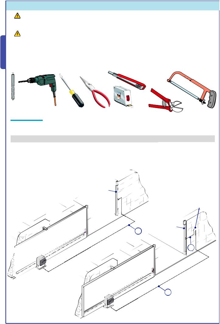
5.3 Cable list
Prepare ducts and tubes suitable for the passage of electrical wiring so as to guarantee protection against mechanical damage. Type of cables recommended:
|
Connection |
Cable type and minimum section |
Maximum length allowed |
|
|
A - Output contacts C - N.C. |
FROR (flexible) 2 x 0.5 mm2 |
30 m* |
|
|
B - Output contacts C - N.C. - N.O. |
FROR (flexible) 3 x 0.5 mm2 |
30 m* |
|
|
C - Output contacts C - N.C. + Power supply 12-24V |
FROR (flexible) 4 x 0.5 mm2 |
30 m* |
|
|
|
|
|
|
*A longer cable may be used as long as the section is greater. |
|
|
||
|
|
DF |
|
|
|
|
|
DFI |
|
|
|
A |
DF |
|
|
|
|
|
|
|
|
|
B |
|
C
4
The data and information provided in this manual are to be considered susceptible to change at any time without warning, by CAME cancelli automatici S.p.A.
 Loading...