

Page 1
Type 8690
Pneumatic Control Unit
Pneumatische Ansteuerung
Unité de commande pneumatique
Operating Instructions
Bedienungsanleitung
Manuel d‘utilisation
Page 2
We reserve the right to make technical changes without notice.
Technische Änderungen vorbehalten.
Sous réserve de modifications techniques.
© 2008 - 2013 Bürkert Werke GmbH
Operating Instructions 1311/06_EU-ml_00805640 / Original DE
Page 3
Type 8690
Pneumatic Control Unit Type 8690
1 OPERATING INSTRUCTIONS ................................................................5
1.1 Symbols .......................................................................................5
1.2 Definition of term / abbreviation .............................................5
2 AUTHORIZED USE ......................................................................................6
2.1 Restrictions .................................................................................6
3 BASIC SAFETY INSTRUCTIONS ..........................................................6
4 GENERAL INFORMATION ........................................................................8
4.1 Contact addresse ...................................................................... 8
4.2 Warranty ......................................................................................8
4.3 Trademarks ..................................................................................8
4.4 Information on the internet ......................................................8
5 DESCRIPTION OF SYSTEM ....................................................................9
5.1 Configuration and function ...................................................... 9
6 TECHNICAL DATA .....................................................................................10
6.1 Conformity .................................................................................10
6.2 Standards ..................................................................................10
6.3 Operating conditions ..............................................................10
6.4 Mechanical data.......................................................................10
6.5 Pneumatic data ........................................................................11
6.6 Electrical data ...........................................................................11
6.7 Type label (example) ...............................................................11
7 INSTALLATION ............................................................................................ 12
7.1 Safety instructions ...................................................................12
7.2 Installation of the Pneumatic Control Unit Type 8690
on process valves of series 21xx .........................................12
7.3 Installation of the Pneumatic Control Unit Type 8690
on process valves of series 20xx .........................................15
7.4 Rotating the actuator module ...............................................18
7.5 Rotating the Pneumatic Control Unit for process valves
belonging to series 20xx ........................................................19
8 PNEUMATIC INSTALLATION ...............................................................20
9 ELECTRICAL INSTALLATION ............................................................... 21
9.1 Safety instructions ...................................................................21
9.2 Electrical installation with cable gland ................................22
9.3 Elektrical installation with circular plug-in connector ......24
9.4 Adjustment of the micro switch or the proximity
switches (option) .....................................................................26
10 MAINTENANCE ........................................................................................... 27
10.1 Service at the air intake filter.................................................27
11 ACCESSORIES ........................................................................................... 28
12 SAFETY POSITIONS .............................................................................. 28
english
3
Page 4
13 DISASSEMBLY ............................................................................................29
13.1 Safety instructions ...................................................................29
13.2 Disassembly the Pneumatic Control Unit ..........................29
14 PACKAGING, TRANSPORT, STORAGE ..........................................30
Type 8690
4
english
Page 5
Type 8690
Operating Instructions
1 OPERATING INSTRUCTIONS
The operating instructions describes the entire life cycle of the device.
Keep these instructions in a location which is easily accessible to
every user, and make these instructions available to every new owner
of the device.
Important safety information.
Read the operating instructions carefully and thoroughly. Study
in particular the chapters entitled “Basic safety instructions” and
“Authorized use”.
▶ The operating instructions must be read and understood.
1.1 Symbols
DANGER!
Warns of an immediate danger.
▶ Failure to observe the warning will result in a fatal or serious injury.
WARNING!
Warns of a potentially dangerous situation.
▶ Failure to observe the warning may result in serious injuries or
death.
CAUTION!
Warns of a possible danger.
▶ Failure to observe this warning may result in a moderate or
minor injury.
NOTE!
Warns of damage to property.
▶ Failure to observe the warning may result in damage to the
device or the equipment.
Indicates important additional information, tips and
recommendations.
refers to information in these operating instructions or in
other documentation.
▶ Designates an instruction to prevent risks.
→ Designates a procedure which you must carry out.
1.2 Definition of term / abbreviation
The term “device” used in these instructions always stands for the
Pneumatic Control Unit Type 8690.
In these instructions, the abbreviation “Ex” always refers to “potentially explosive”.
english
5
Page 6
Type 8690
Authorized use
2 AUTHORIZED USE
Non-authorized use of the Pneumatic Control Unit Type
8690 may be a hazard to people, nearby equipment and the
environment.
The device is designed to be mounted on pneumatic actuators of
process valves for the control of media.
▶ Do not expose the device to direct sunlight.
▶ Use according to the authorized data, operating conditions and
conditions of use specified in the contract documents and operating instructions. These are described in the chapter entitled “6
Technical data”.
▶ The device may be used only in conjunction with third-party devices
and components recommended and authorized by Bürkert.
▶ In view of the large number of options for use, before installation, it
is essential to study and if necessary to test whether the Pneumatic
Control Unit is suitable for the actual use planned.
▶ Correct transportation, correct storage and installation and care-
ful use and maintenance are essential for reliable and faultless
operation.
▶ Use the Pneumatic Control Unit Type 8690 only as intended.
2.1 Restrictions
If exporting the system/device, observe any existing restrictions.
3 BASIC SAFETY
INSTRUCTIONS
These safety instructions do not make allowance for any
• contingencies and events which may arise during the installation,
operation and maintenance of the devices.
• local safety regulations, whereby the operator is responsible for their
compliance, by the installation personnel too.
DANGER!
Risk of injury from high pressure in the equipment/device.
▶ Before working on equipment or device, switch off the pressure
and deaerate/drain lines.
Risk of electric shock.
▶ Before working on equipment or device, switch off the power
supply and secure to prevent reactivation.
▶ Observe applicable accident prevention and safety regulations
for electrical equipment.
6
english
Page 7
Type 8690
Basic safety instructions
General hazardous situations.
To prevent injury, ensure:
▶ In the potentially explosion-risk area the Pneumatic Control Unit
Type 8690 may be used only according to the specification on the
separate approval sticker. For use observe the additional instructions enclosed with the device together with safety instructions
for the explosion-risk area.
▶ Devices without a separate approval sticker may not be used in a
potentially explosive area.
▶ that the system cannot be activated unintentionally.
▶ Installation and repair work may be carried out by authorized
technicians only and with the appropriate tools.
▶ After an interruption in the power supply or pneumatic supply,
ensure that the process is restarted in a defined or controlled
manner.
▶ The device may be operated only when in perfect condition and
in consideration of the operating instructions.
▶ The general rules of technology apply to application planning and
operation of the device.
To prevent damage to property of the device, ensure:
▶ Do not feed any aggressive or flammable media into the pilot air
port.
▶ Do not feed any liquids into the pilot air port.
▶ When unscrewing and screwing in the transparent cap, do not
hold the actuator of the process valve but the connection housing
of Type 8690.
▶ Do not put any loads on the housing (e.g. by placing objects on
it or standing on it).
▶ Do not make any external modifications to the device housings.
english
7
Page 8
Type 8690
General information
4 GENERAL INFORMATION
4.1 Contact addresse
Germany
Bürkert Fluid Control Systems
Sales Center
Chr.-Bürkert-Str. 13-17
D-74653 Ingelfingen
Tel. : 07940 - 10 91 111
Fax: 07940 - 10 91 448
E-mail: info@de.burkert.com
International
Contact addresses are found on the final pages of the printed operating manual.
You can also find information on the Internet under:
www.burkert.com
4.2 Warranty
The warranty is only valid if the device is used as authorized in accordance with the specified application conditions.
4.3 Trademarks
Brands and trademarks listed below are trademarks of the corresponding companies / associations / organizations
Loctite Henkel Loctite Deutschland GmbH
4.4 Information on the internet
The operating instructions and data sheets for Type 8690 can be found
on the Internet at:
www.burkert.com
8
english
Page 9
Type 8690
Description of system
5 DESCRIPTION OF SYSTEM
5.1 Configuration and function
The Pneumatic Control Unit Type 8690 can control single or doubleacting process valves.
The Pneumatic Control Unit Type 8690 has been optimized for
integrated, modular installation on process valves of the 21xx series.
The module configuration permits a variety of expansion steps.
For installation on the 20xx series there is a special model which is
described in Chapter “5.1.2”.
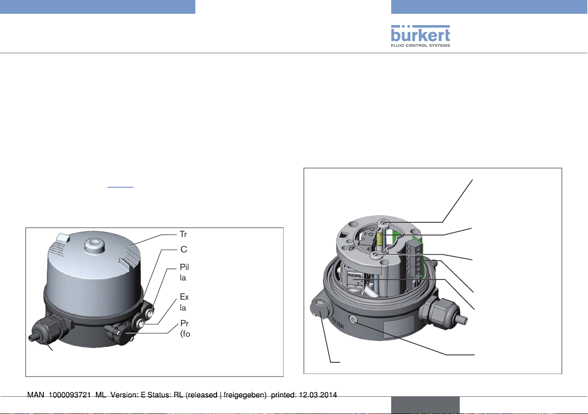
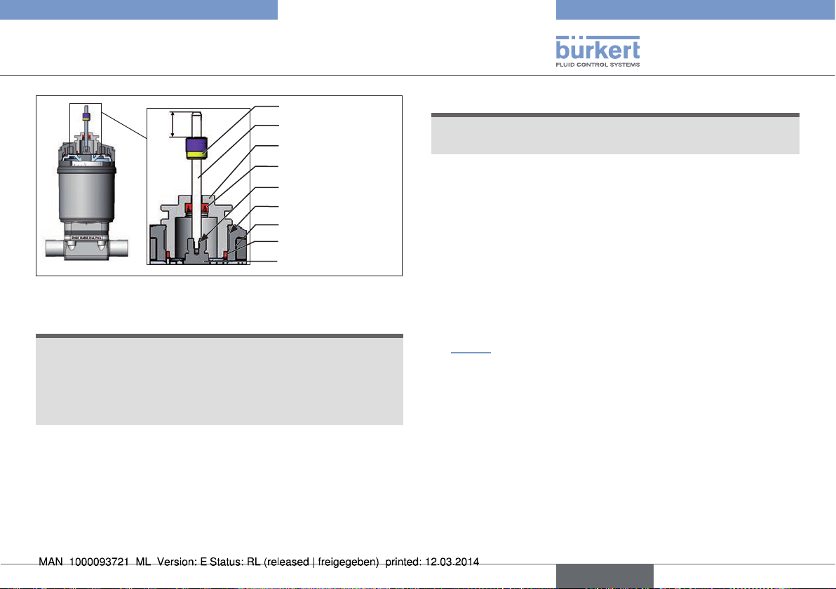
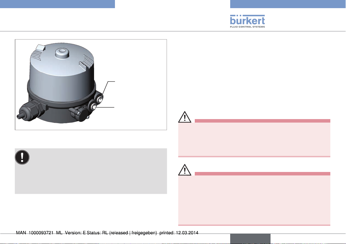
5.1.1 Pneumatic Control Unit for integrated
installation on 21xx series
Transparent cap
Connection housing
Pilot air port
label: 1
Exhaust air port
label: 3
Pressure limiting valve
(for protection against
too high internal pressure
Cable gland M16 x 1.5 or
Circular plug-in connector M12 x 1
Fig. 1: Configuration and function (1)
in case of error)
Optical position indicator:
The device status is displayed on the pneumatic control unit (yellow
mark).
Option: Electrical position feedback
Optionally mechanical limit switches (micro switches) or inductive limit
switches (proximity switches) can measure the valve position.
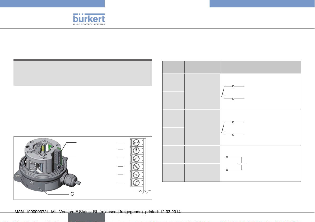
View without transparent cap:
Screw for adjustment
of the lower micro
switch or the lower
proximity switch
Optical position indicator (yellow mark)
Screw for adjustment
of the upper proximity
switch
Screw terminals
Pilot valve (3/2-way
or 5/2-way solenoid
valve with hand lever)
Air intake filter (exchangeable)
Fig. 2: Configuration and function (2)
Fastening screws (2x)
english
9
Page 10
Type 8690
Description of system
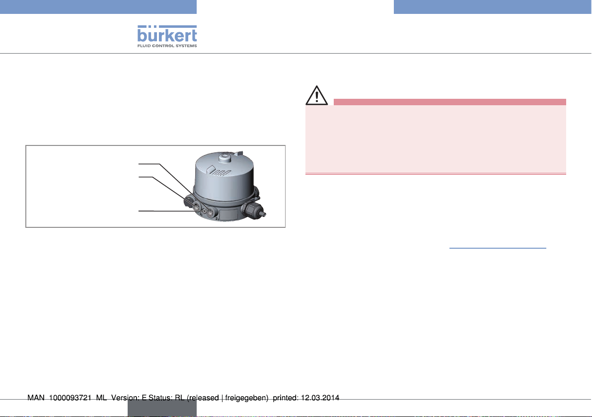
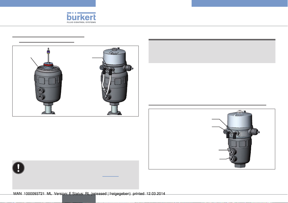
5.1.2 Model for control of process valves
belonging to the 20xx series
A special model enables the Pneumatic Control Unit Type 8690 to be
attached to process valves belonging to the 20xx series.
This model has a different connection housing so that the pilot air ports
can be connected to the outside of the actuator.
Pilot air outlet 2
Pilot air outlet 2
Fastening screws (2 x)
Fig. 3: Model for process valves, 20xx series
1
2
6 TECHNICAL DATA
6.1 Conformity
In accordance with the EC Declaration of conformity, the Pneumatic
Control Unit Type 8690 is compliant with the EC Directives.
6.2 Standards
The applied standards on the basis of which compliance with the EC
Directives is confirmed are listed in the EC type examination certificate
and/or the EC Declaration of Conformity.
6.3 Operating conditions
WARNING!
Solar radiation and temperature fluctuations may cause malfunctions or leaks.
▶ If the device is used outdoors, do not expose it unprotected to
the weather conditions.
▶ Ensure that the permitted ambient temperature does not exceed
the maximum value or drop below the minimum value.
Ambient temperature: see type label
Degree of protection: IP65 / IP67 according to EN 60529
(only if cables, plugs and sockets have
been connected correctly and in compliance with the exhaust air concept in
chapter “8 Pneumatic installation”).
6.4 Mechanical data
Dimensions: see data sheet
Housing material external PPS, PC
Sealing material external EPDM
internal NBR
Stroke range of valve spindle Micro switch 7 – 28 mm
Proximity switch 2 – 28 mm
10
english
Page 11
Type 8690
Description of system
6.5 Pneumatic data
Control medium neutral gases, air, Quality classes in accordance
with DIN ISO 8573-1
Dust content Class 5 max. particle size 40 μm,
max. particle density 10 mg/m
3
Water content Class 3 max. pressure dew point -20 °C or
min. 10 °C below the lowest operating
temperature
Oil content Class 5 max. 25 mg/m
3
Temperature range -10 to +50 °C
Pressure range 3 to 7 bar
Air output of pilot valve 250 I
/min
N
(for aeration and deaeration, QNn-value
according to definition for pressure
drop from 7 to 6 bar absolute)
Connections Plug-in hose connector ∅6 mm / ¼”
Socket connection G 1/8
6.6 Electrical data
Connections: Cable gland M16 x 1.5, wrench size 22
(clamping area 5 – 10 mm)
with screw terminals
for cable cross-sections 0.14 – 1.5 mm²
Circular plug-in connector M12 x 1, 8-pole
Supply voltage
Pilot valve 24 V DC ± 10 %, residual ripple 10 %
Micro switch 24 V DC max. 2 A
Proximity switches 24 V DC max. 100 mA per proximity switch
Power consumption of pilot valve: 1 W
Position feedback
(option): 1 or 2x Micro switch (24 V DC)
1 or 2x Proximity switch (24 V DC),
normally open PNP
1 or 2x Proximity switch NAMUR (8 V DC)
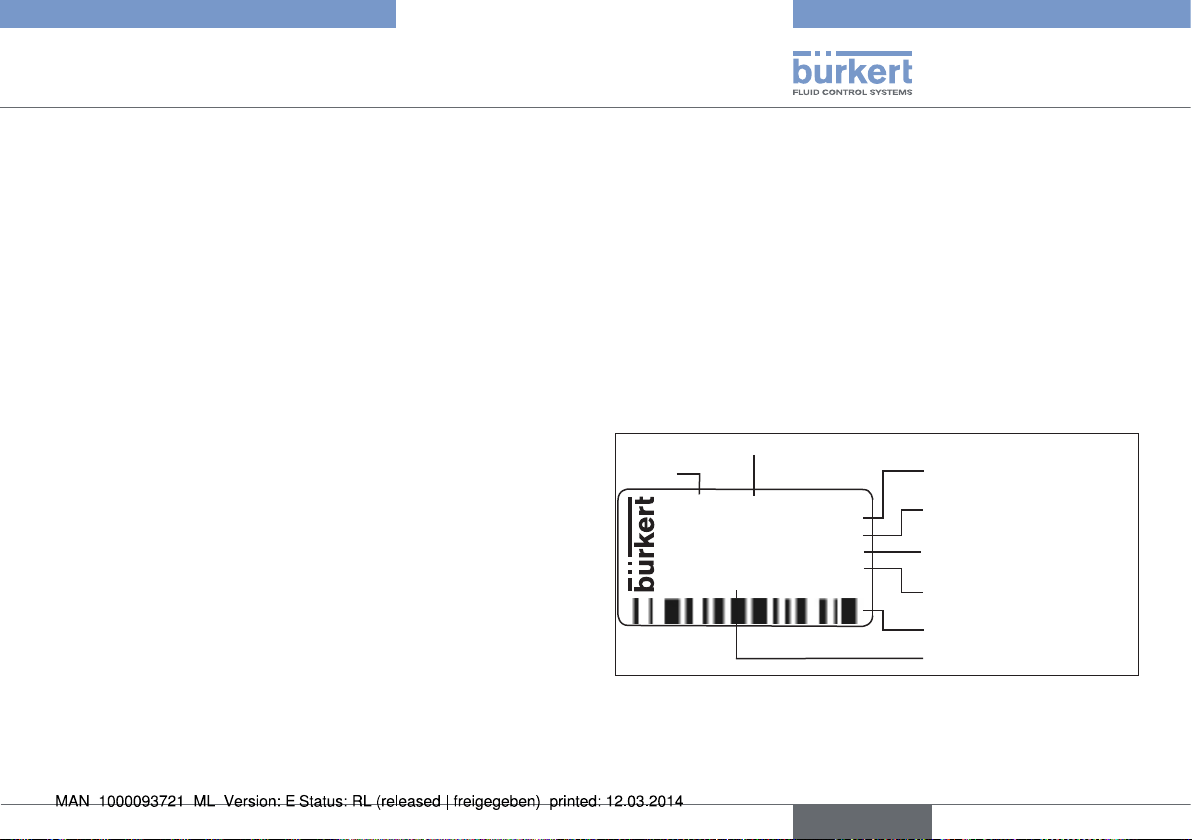
6.7 Type label (example)
Supply voltage / Control
Type
8690 24 V/DC
single act Pilot 0,6
Pmax 7 bar 2 sw.mec.
Tamb 0°C - +55°C
S/N 001000
00185114
D-74653 Ingelfingen
CE
W14UN
Fig. 4: Example of type label
Control function - pilot valve
Max. operating pressure limit switch
Ambient temperature
Serial number - CE mark
Bar code
Identification number
english
11
Page 12
Type 8690
Installation
7 INSTALLATION
Only for Pneumatic Control Unit without pre-assembled
process valve.
7.1 Safety instructions
DANGER!
Risk of injury from high pressure in the equipment/device.
▶ Before working on equipment or device, switch off the pressure
and deaerate/drain lines.
Risk of electric shock.
▶ Before working on equipment or device, switch off the power
supply and secure to prevent reactivation.
▶ Observe applicable accident prevention and safety regulations
for electrical equipment.
WARNING!
Risk of injury from improper installation.
▶ Installation may be carried out by authorized technicians only
and with the appropriate tools.
Risk of injury from unintentional activation of the system and
an uncontrolled restart.
▶ Secure system from unintentional activation.
▶ Following installation, ensure a controlled restart.
7.2 Installation of the Pneumatic
Control Unit Type 8690 on
process valves of series 21xx
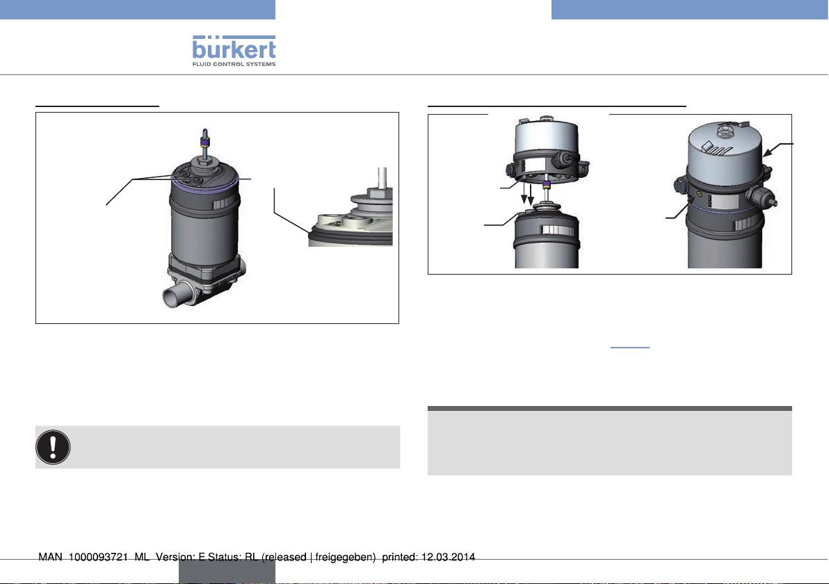
Procedure:
1. Install switch spindle:
Transparent cap
Pilot air ports
(plug-in hose con-
nectors with collets or
threaded bushings)
Actuator
Fig. 5: Installation of the switch spindle (1), 21xx series
→ Unscrew the transparent cap on the actuator and unscrew the
position display (yellow cap) on the spindle extension.
→ For model with plug-in hose connector, remove the collets (white
nozzles) from both control air connections (if present).
12
english
Page 13
Type 8690
Installation
Switch cam
10
Fig. 6: Installation of switch spindle (2), 21xx series
NOTE!
Improper installation may damage the groove ring in the
guide element.
The groove ring is already be pre-assembled in the guide element
and must be “locked into position” in the undercut.
▶ When installing the switch spindle, do not damage the groove ring.
Switch spindle
Guide element
Groove ring
max. 1 Nm
max. 5 Nm
Actuator cover
O-ring
Spindle extension
→ Push the switch spindle through the guide element.
NOTE!
Screw locking paint may contaminate the groove ring.
▶ Do not apply any screw locking paint to the switch spindle.
→ To secure the switch spindle, apply some screw locking paint
(Loctite 290) in the tapped bore of the spindle extension in the
actuator.
→ Check that the O-ring is correctly positioned.
→ Screw the central screw to the actuator cover (maximum torque:
5 Nm).
→ Screw switch spindle onto the spindle extension. To do this,
there is a slot on the upper side (maximum torque: 1 Nm).
→ Position the switch cam on the switch spindle so that the distance
between the switch cam and top of the spindle is 10 mm (see
“Fig. 6”)
english
13
Page 14
Type 8690
Installation
2. Install sealing rings
Form seal
Pilot air ports
Caution:
Collets must not be
fitted !
Fig. 7: Installing of the sealing rings, 21xx series
Installation of
the form seal
→ Pull the form seal onto the actuator cover (smaller diameter
points upwards).
→ Check that the O-rings are correctly positioned in the control air
connections.
When the Pneumatic Control Unit is being installed, the collets
of the pilot air ports must not be fitted to the actuator.
3. Installation of the Pneumatic Control Unit:
Connection
pieces
Pilot air
ports
Fig. 8: Installation of the Pneumatic Control Unit, 21xx series
Fastening
screws
max. 0,5 Nm
→ Align the Pneumatic Control Unit until the connection pieces
of the Pneumatic Control Unit can be inserted into the pilot air
ports of the actuator (see also “Fig. 8”).
→ Push the Pneumatic Control Unit, without turning it, onto the
actuator until no gap is visible on the form seal.
NOTE!
Too high torque when screwing in the fastening screw does
not ensure degree of protection IP65 / IP67.
▶ The fastening screws may be tightened to a maximum torque of
0.5 Nm only.
→ Attach the Pneumatic Control Unit to the actuator using the two
side fastening screws. In doing so, tighten the screws only handtight (max. torque: 0.5 Nm).
14
english
Page 15
Type 8690
Installation
7.3 Installation of the Pneumatic
Control Unit Type 8690 on
process valves of series 20xx
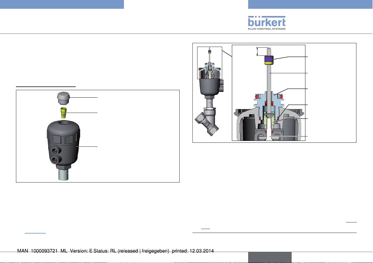
Procedure:
1. Install switch spindle
Transparent cap
Position indicator
Actuator
Fig. 9: Installation of the switch spindle (1), series 20xx
→ Unscrew the transparent cap on the actuator.
→ Using a hexagon socket key, unscrew the orange/yellow position
indicator from the inside of the actuator.
→ Press the O-ring downwards into the cover of the actuator (see
“Fig. 10”).
10 mm
Fig. 10: Installation of the switch spindle (2), series 20xx
Switch cam
Switch spindle
Guide element
O-ring
Plastic part of the
switch spindle
Spindle (actuator)
→ Manually screw the switch spindle (and the plugged-on guide
element) together with the plastic part onto the spindle of the
actuator, but do not tighten spindle yet.
→ Tighten the guide element with a face wrench
cover (torque: 8.0 Nm).
1)
into the actuator
→ Tighten the switch spindle on the spindle of the actuator. To do
this, there is a slot on the upper side (torque: 1.0 Nm).
→ Position the switch cam on the switch spindle so that the distance
between the switch cam and top of the spindle is 10 mm (see “Fig.
10”).
1) journal Ø: 3 mm; journal gap: 23.5 mm
english
15
Page 16
Type 8690
Installation
2. Installation of the cover ring and
the Pneumatic Control Unit:
Cover ring
Fig. 11: Installation of the cover ring and the Pneumatic Control
Unit, series 20xx
Fastening screws
max. 0.5 Nm
→ Pull the cover ring onto the actuator cover
(for actuator sizes ∅ 50 and ∅ 63 only).
→ Push the Pneumatic Control Unit onto the actuator.
→ Press the Pneumatic Control Unit all the way down as far as the
actuator and turn it into the required position.
Ensure that the pneumatic connections of the Pneumatic
Control Unit and those of the actuator are situated preferably vertically one above the other (see “Fig. 11”).
If they are positioned differently, longer hoses may be
required other than those supplied in the accessory kit.
NOTE!
Too high torque when screwing in the fastening screw does
not ensure degree of protection IP65 / IP67.
▶ The fastening screws may be tightened to a maximum torque of
0.5 Nm only.
→ Attach the Pneumatic Control Unit to the actuator using the two
side fastening screws. In doing so, tighten the fastening screws
hand-tight only (max. torque: 0.5 Nm).
3. Installation of the pneumatic connection on the actuator
Pilot air outlet 2
Pilot air outlet 2
Upper pilot air port
Lower pilot air port
Fig. 12: Installation of the pneumatic connection, 20xx series
1
2
16
english
Page 17
Type 8690
Installation
→ Screw the plug-in hose connectors onto the Pneumatic Control
Unit and the actuator.
→ Using the hoses supplied in the accessory kit, make the con-
nection between the Pneumatic Control Unit and the actuator
with the following “Tab. 1: Pneumatic connection to actuator”.
NOTE!
Damage or malfunction due to ingress of dirt and moisture.
▶ To comply with degree of protection IP65 / IP67, connect the
pilot air aoutlet which is not required to the free pilot air port of
the actuator or seal with a plug.
“In rest position” means that the pilot valves of the Pneumatic Control Unit Type 8690 are isolated or not actuated.
If the ambient air is humid, a hose can be connected between
pilot air outlet 22 of the Pneumatic Control Unit and the
unconnected pilot air port of the actuator for control function
A or control function B. As a result, the spring chamber of
the actuator is supplied with dry air from the vent duct of the
Pneumatic Control Unit.
Control function Pneumatic connection Type 8690
with actuator
Process valve closed
in rest position
A
(by spring force)
Pilot air outlet
Type 8690
2
1
2
2
Pilot air port
actuator
lower pilot air port
of the actuator
should be connected to the
upper pilot air port
of the actuator
upper pilot air port
of the actuator
should be connected to the
lower pilot air port
Process valve open
in rest position
B
(by spring force)
2
1
2
2
of the actuator
lower pilot air port
of the actuator
upper pilot air port
of the actuator
upper pilot air port
of the actuator
lower pilot air port
of the actuator
Process valve closed
in rest position
I
Process valve open
in rest position
2
1
2
2
2
1
2
2
Tab. 1: Pneumatic connection to actuator
english
17
Page 18
7.4 Rotating the actuator module
The actuator module (Pneumatic Control Unit and actuator)
can be rotated for straight seat valves and angle seat valves
only.
The position of the connections can be aligned steplessly by rotating the
actuator module (Pneumatic Control Unit and actuator) through 360°.
Process valves Type 2100 and 2100: Only the entire actuator
module can be rotated. The Pneumatic Control Unit cannot
be rotated contrary to the actuator.
The process valve must be in the open position for alignment
of the actuator module.
DANGER!
Type 8690
Installation
Actuator
module
Key contour
Nipple
Fig. 13: Rotating the actuator module
Hexagon
Nipple
with hexagonwithout hexagon
Risk of injury from high pressure in the equipment/device.
▶ Before working on equipment or device, switch off the pressure
and deaerate/drain lines.
Procedure:
→ Clamp valve body in a holding device (only required if the process
valve has not yet been installed).
→ Control function A: Open process valve.
18
english
→ Using a suitable open-end wrench, counter the wrench flat on
the pipe.
→ Actuator module without hexagon:
Fit special key2) exactly in the key contour on the underside of
the actuator.
→ Actuator module with hexagon:
Place suitable open-end wrench on the hexagon of the actuator.
2) The special key (665702) is available from your Bürkert sales office.
Page 19
Type 8690
Installation
WARNING!
Risk of injury from discharge of medium and pressure.
If the direction of rotation is wrong, the body interface may
become detached.
▶ Rotate the actuator module in the specified direction only (see
“Fig. 14”).
→ Actuator module without hexagon:
Rotate clockwise (as seen from below) to bring the actuator
module into the required position.
→ Actuator module with hexagon:
Rotate counter-clockwise (as seen from below) to bring the
actuator module into the required position.
Open-end wrench
Special key
with hexagon
without hexagon
Fig. 14: Rotating with special key / open-end wrench
7.5 Rotating the Pneumatic
Control Unit for process valves
belonging to series 20xx
If the connecting cables or hoses cannot be fitted properly following
installation of the process valve, the Pneumatic Control Unit can be
rotated contrary to the actuator.
Fastening
screw (2x)
Pneumatic
connection
Fig. 15: Rotating the Pneumatic Control Unit, series 20xx
Pneumatic
Control Unit
Actuator
english
19
Page 20
Type 8690
Pneumatic installation
Procedure
→ Loosen the pneumatic connection between the Pneumatic
Control Unit and the actuator.
→ Loosen the fastening screws (hexagon socket wrench size 2.5).
→ Rotate the Pneumatic Control Unit into the required position.
NOTE!
Too high torque when screwing in the fastening screw does
not ensure degree of protection IP65 / IP67.
▶ The fastening screw may be tightened to a maximum torque of
0.5 Nm only.
→ Tighten the fastening screws hand-tight only (maximum torque:
0.5 Nm).
→ Re-attach the pneumatic connections between the Pneumatic
Control Unit and the actuator. If required, use longer hoses.
8 PNEUMATIC INSTALLATION
DANGER!
Risk of injury from high pressure in the equipment/device.
▶ Before working on equipment or device, switch off the pressure
and deaerate/drain lines.
Procedure:
→ Connect the control medium to the pilot air port (1)
(3 to 7 bar, oil, water and dust-free instrument air).
→ Attach the exhaust airline or a silencer to the exhaust air con-
nection (3).
Important information for the problem-free functioning of the
device:
▶ The installation must not cause back pressure to build up.
▶ Select a hose for the connection with an adequate cross-section.
▶ The exhaust air line must be designed in such a way that no water
or other liquid can get into the device through the exhaust air
connection.
20
english
Page 21
Type 8690
Electrical installation
Pilot air port
label: 1
9 ELECTRICAL INSTALLATION
Two kinds of connections are used for the electrical bonding of the
Pneumatic Control Unit:
• Cable gland
with cable gland M16 x 1.5 and screw terminals
• Multi-pole
with circular plug-in connector M12 x 1, 8-pole.
Exhaust air
connection
label: 3
Fig. 16: Pneumatic connection
Caution: (Exhaust air concept):
In compliance with degree of protection IP67, an exhaust air
line must be installed in the dry area.
Keep the adjacent supply pressure always at least 0.5 –
1 bar above the pressure which is required to move the
actuator to its end position.
9.1 Safety instructions
DANGER!
Risk of electric shock.
▶ Before working on equipment or device, switch off the power
supply and secure to prevent reactivation.
▶ Observe applicable accident prevention and safety regulations
for electrical equipment.
WARNING!
Risk of injury from improper installation.
▶ Installation may be carried out by authorized technicians only
and with the appropriate tools.
Risk of injury from unintentional activation of the system and
an uncontrolled restart.
▶ Secure system from unintentional activation.
▶ Following installation, ensure a controlled restart.
english
21
Page 22
Type 8690
Electrical installation
9.2 Electrical installation
with cable gland
NOTE!
Breakage of the pneumatic connection pieces due to rotational impact.
▶ When unscrewing and screwing the transparent cap, do not hold
the actuator of the process valve but the connection housing.
Procedure:
→ Open the Pneumatic Control Unit: unscrewing the transparent
cap in an anticlockwise direction.
→ Push the cables through the cable gland.
→ Connect the wires according to the model (options) of the Pneu-
matic Control Unit.
→ Close the Pneumatic Control Unit.
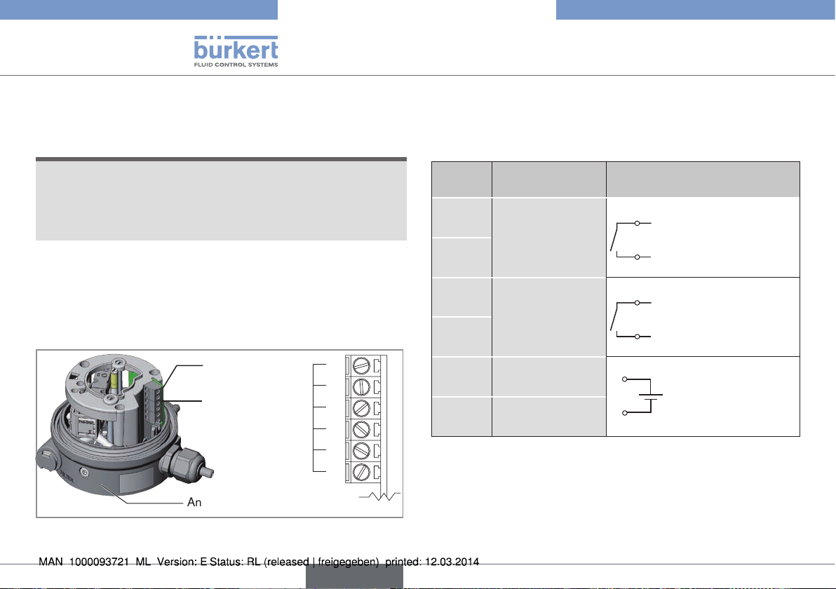
Printed
circuit board
Screw
terminals
Connection housing
Fig. 17: Position of the screw terminals
1
2
3
4
Klemmen-
5
Nummerierung
6
9.2.1 Connection diagram
with micro switches
(mechanical limit switches)
Terminal Configuration External circuit
1
Micro switch
top (NO)
2
3
Micro switch
bottom (NO)
4
Valve control
5
0 / 24 V
Valve control
6
GND
Tab. 2: Connection diagram with micro switches
1
2
3
4
5
6
Micro switch top (NO)
Micro switch top (NO)
Micro switch bottom (NO)
Micro switch bottom (NO)
0/24 V DC ± 10 %
Residual ripple 10 %
22
english
Page 23
Type 8690
Electrical installation
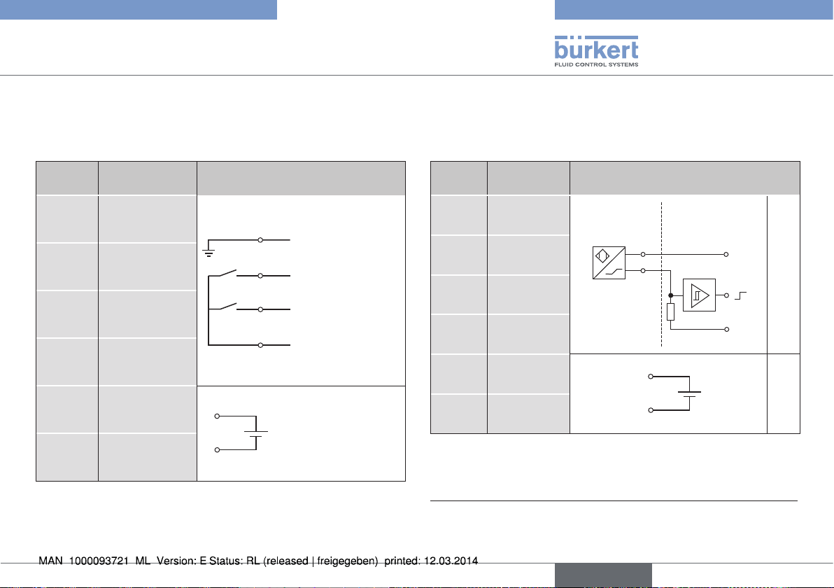
9.2.2 Connection diagram
with three-wire proximity switches
(inductive limit switches)
Terminal Configuration External circuit
INI - (GND)
1
Supply
INI 1 OUT
2
Output
INI 2 OUT
3
Output
INI + (24 V DC)
4
Supply
Valve control
5
6
0 / 24 V DC
Valve control
GND
5
6
Tab. 3: Connection diagram with three-wire proximity switches
1
2
3
4
GND
Output 1 (24 V)
Output 2 (24 V)
+24 V DC
0/24 V DC ±10 %
Residual ripple 10 %
9.2.3 Connection diagram
with two-wire proximity switches
(inductive NAMUR limit switches)
Terminal Configuration External circuit
1 INI Top +
2 INI Top -
3 INI Bottom +
4 INI Bottom -
Valve control
5
+
Valve control
6
GND
Explosion
protected area
NAMURSensor
Non-hazardous
area
1 / 3
+8,2 V DC
2 / 4
R
0 V
5
6
Tab. 4: Connection diagram with two-wire proximity switches
3) (recommended by NAMUR) Also observe the type-examination certificate
from Turck KEMA 02 ATEX 1090X
4) Signal from barrier see PTB 07 ATEX 2048
3)
4)
english
23
Page 24
Type 8690
Electrical installation
9.3 Elektrical installation with
circular plug-in connector
DANGER!
Risk of electric shock.
▶ Before working on equipment or device, switch off the power
supply and secure to prevent reactivation.
▶ Observe applicable accident prevention and safety regulations
for electrical equipment.
NOTE!
Breakage of the pneumatic connection pieces due to rotational impact.
▶ When unscrewing and screwing the transparent cap, do not hold
the actuator of the process valve but the connection housing.
→ Connect the pins according to the model (options) of the Pneu-
matic Control Unit
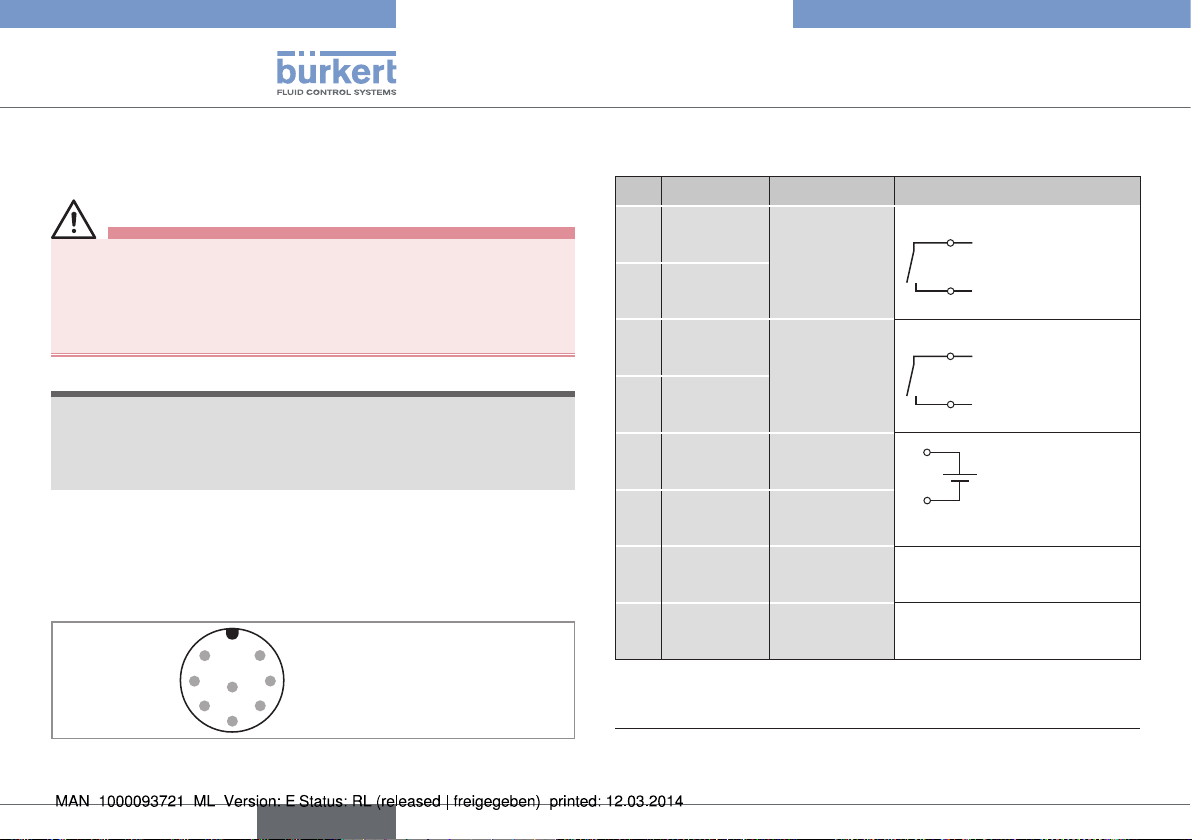
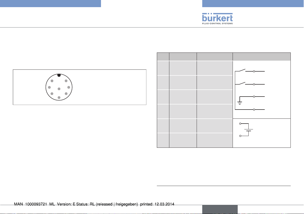
9.3.1 Pin assignment with micro switches
(mechanical limit switches)
2
1
8
73
5
64
Fig. 18: Circular connector M12x1, 8-pole
Pin assignment with micro switches (mechanical limit switches)
Pin Wire color5)Configuration External circuit
1 white
3 green
brown
2
yellow
4
5 grey
6 pink
Micro switch
top (NO)
Micro switch
bottom (NO)
Valve control
0 / 24 V
Valve control
GND
1
Micro switch top
3
Micro switch top
2
Micro switch bottom
4
Micro switch bottom
5
0 / 24 V DC
± 10 %
6
Residual ripple
10 %
7 not used
8 not used
Tab. 5: Pin assignment with micro switches
5)
The indicated colors refer to the connecting cable available as an
accessory (919061)
24
english
Page 25
Type 8690
Electrical installation
9.3.2 Pin assignment
with three-wire proximity switches
(inductive limit switches)
Pin assignment of the circular connector (M12x1, 8-pole):
2
1
8
73
5
64
Fig. 19: Circular connector M12x1, 8-pole
Pin assignment with three-wire proximity switches
(inductive limit switches)
Pin Wire color6)Configuration External circuit
1 white
brown
2
INI Bottom OUT
Output
INI Top OUT
Output
1
Output 1
(24 V)
2
Output 2
(24 V)
3 green
yellow
4
5 grey
6 pink
INI - (GND)
Supply
INI + (24 V DC)
Supply
Valve control
0 / 24 V
Valve control
GND
3
4
5
GND
+24 V DC
0 / 24 V DC
± 10 %
6
Residual ripple
10 %
Tab. 6: Pin assignment with three-wire proximity switches
6)
The indicated colors refer to the connecting cable available as an
accessory (919061)
english
25
Page 26
Type 8690
Electrical installation
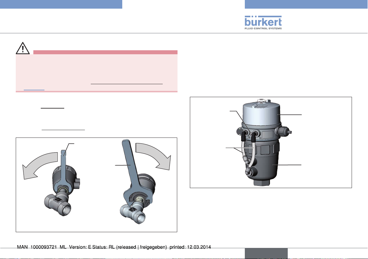
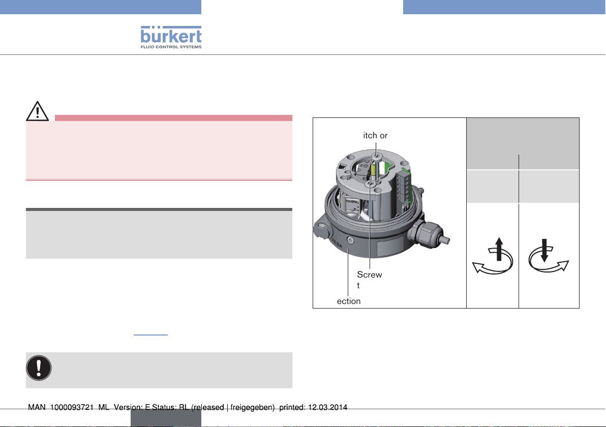
9.4 Adjustment of the micro switch
or the proximity switches (option)
DANGER!
Risk of electric shock.
▶ Before working on equipment or device, switch off the power
supply and secure to prevent reactivation.
▶ Observe applicable accident prevention and safety regulations
for electrical equipment.
NOTE!
Breakage of the pneumatic connection pieces due to rotational impact.
▶ When unscrewing and screwing the transparent cap, do not hold
the actuator of the process valve but the connection housing.
Procedure:
→ Open the Pneumatic Control Unit: unscrewing the transparent
cap in an anticlockwise direction.
→ Adjust the lower micro switch or the proximity switches via the
adjusting screw(s) (see “Fig. 20”).
In the case of the option with micro switches only the lower
micro switch can be set with the screw, the upper micro
switch is fixed.
→ Check the switching point(s) using suitable measuring
equipment.
→ Close the Pneumatic Control Unit.
Screw for adjustment of the lower
micro switch or the lower proximity
switch
Screw for adjustment of
the upper proximity switch
Connection housing
Fig. 20: Adjustment of the micro switch and the proximity switches
Adjustment of the lower
micro switch or the proximity switches
upwards downwards
turn screw
clockwise
turn screw
anticlockwise
26
english
Page 27
Type 8690
Maintenance
10 MAINTENANCE
The Pneumatic Control Unit is maintenance-free when operated
according to the instructions in this manual.
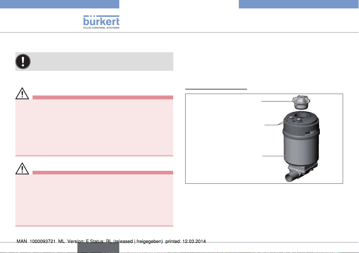
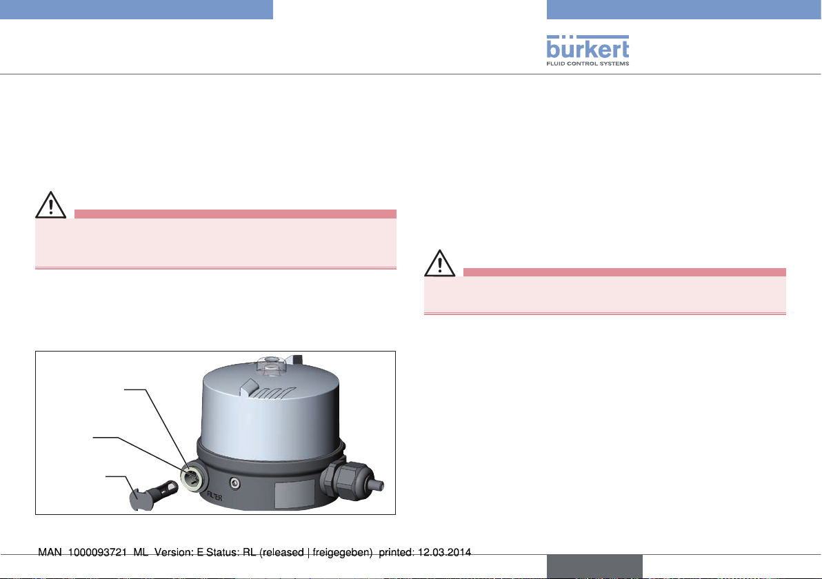
10.1 Service at the air intake filter
DANGER!
Risk of injury from high pressure in the equipment/device.
▶ Before working on equipment or device, switch off the pressure
and deaerate/drain lines.
To protect the internal solenoid valves and the actuator, the pressure
supply air is filtered.
The direction of flow of the air intake filter in installed state is from
the inside to the outside through the filter material.
Quick plug-in
connector
O-ring
Air intake
filter
Procedure:
→ Unlock the quick plug-in connector by pressing the holding
element and pulling out the air intake filter (if necessary, use a
suitable tool in between the recesses in the head of the filter).
→ Clean the filter or, if necessary, replace the filter.
→ Check inner O-ring and, if required, clean.
→ Insert the air intake filter all the way into the quick plug-in
connector.
DANGER!
Risk of injury due to improper installation.
▶ Ensure that the air intake filter is installed correctly.
→ Check that the air intake filter is secure.
Fig. 21: Service on the air intake filter
english
27
Page 28

Type 8690
Accessories
11 ACCESSORIES
Designation Order no.
Connection cable M12 x 1, 8-pole 919061
Tab. 7: Accessories
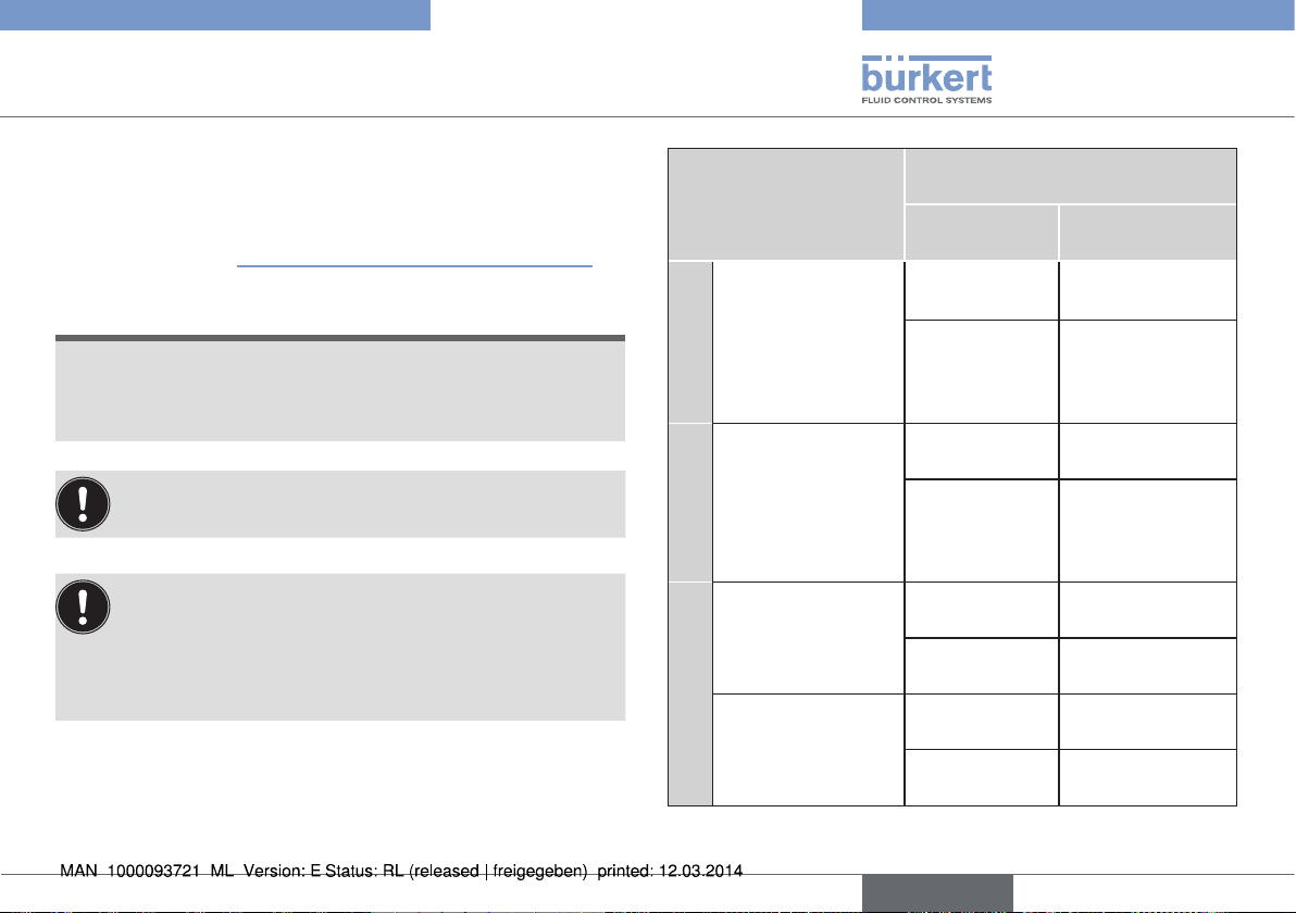
12 SAFETY POSITIONS
Safety positions after failure of the electric or pneumatic auxiliary energy:
Operating mode Designation
Single-acting
up
down
up
down
up
down
control
function A
Single-acting
control
function B
Double-acting
control
function I
Safety positions after failure
of the auxiliary energy
Electrical Pneumatic
down down
up up
down not defined
28
Tab. 8: Safety Positions
english
Page 29

Type 8690
Disassembly
13 DISASSEMBLY
13.1 Safety instructions
DANGER!
Risk of injury from high pressure in the equipment/device.
▶ Before working on equipment or device, switch off the pressure
and deaerate/drain lines.
Risk of electric shock.
▶ Before working on equipment or device, switch off the power
supply and secure to prevent reactivation.
▶ Observe applicable accident prevention and safety regulations
for electrical equipment.
WARNING!
Risk of injury from improper disassembly.
▶ Disassembly may be carried out by authorized technicians only
and with the appropriate tools.
Risk of injury from unintentional activation of the system and
an uncontrolled restart.
▶ Secure system from unintentional activation.
▶ Following disassembly, ensure a controlled restart.
13.2 Disassembly the Pneumatic
Control Unit
Procedure:
1. Pneumatic connection
DANGER!
Risk of injury from high pressure in the equipment/device.
▶ Before working on equipment or device, switch off the pressure
and deaerate/drain lines.
→ Loosen the pneumatic connection.
→ Series 20xx:
Loosen the pneumatic connection between Pneumatic Control
Unit and actuator.
2. Electrical connection
DANGER!
Risk of electric shock.
▶ Before working on equipment or device, switch off the power
supply and secure to prevent reactivation.
▶ Observe applicable accident prevention and safety regulations
for electrical equipment.
Circular plug-in connector:
→ Loosen the circular connector.
english
29
Page 30

Type 8690
Packaging, transport, storage
Cable gland:
→ Open the Pneumatic Control Unit: unscrewing the transparent
cap in an anticlockwise direction.
→ Unscrew the screw terminals and pull out cables.
3. Mechanical connection
→ Loosen the fastening screws.
→ Remove the Pneumatic Control Unit upwards.
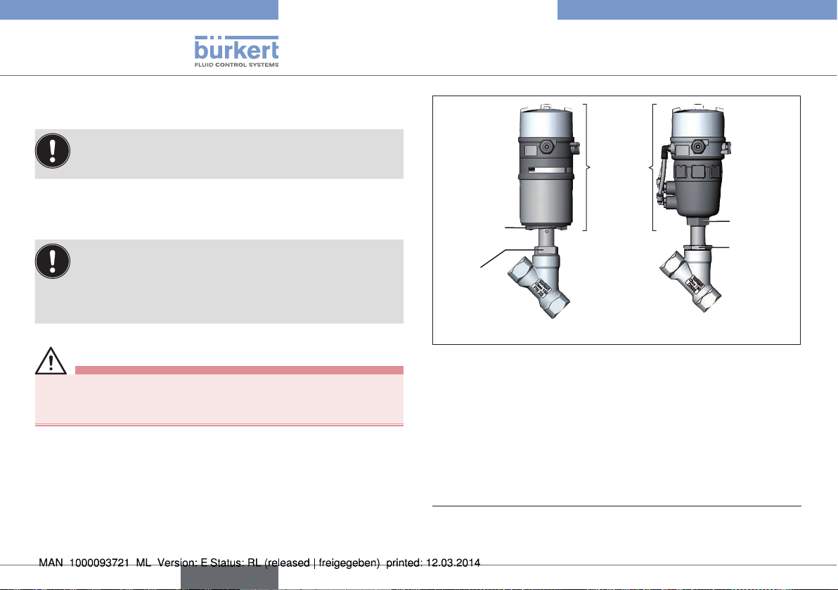
Transparent cap
Pneumatic
Control Unit
Cable gland
Fastening screws
(2x)
Pneumatic
connections
Actuator
Pneumatic con-
nection to the
actuator
Series 20xx
Fig. 22: Disassembly the Pneumatic Control Unit
Series 21xx
14 PACKAGING, TRANSPORT,
STORAGE
NOTE!
Transport damages.
Inadequately protected equipment may be damaged during
transport.
▶ During transportation protect the device against wet and dirt in
shock-resistant packaging.
▶ Avoid exceeding or dropping below the permitted storage
temperature.
Incorrect storage may damage the device.
▶ Store the device in a dry and dust-free location!
▶ Storage temperature -20 – +65 °C.
Damage to the environment caused by device components
contaminated with media.
▶ Dispose of the device and packaging in an environmentally
friendly manner.
▶ Observe applicable regulations on disposal and the environment.
30
english
Page 31
Typ 8690
Pneumatische Ansteuerung Typ 8690
1 DIE BEDIENUNGSANLEITUNG .........................................................33
1.1 Darstellungsmittel ....................................................................33
1.2 Begriffsdefinition / Abkürzung ..............................................33
2 BESTIMMUNGSGEMÄSSE VERWENDUNG................................34
2.1 Beschränkungen ......................................................................34
3 GRUNDLEGENDE SICHERHEITSHINWEISE .............................. 34
4 ALLGEMEINE HINWEISE ....................................................................... 36
4.1 Kontaktadresse ........................................................................36
4.2 Gewährleistung ........................................................................36
4.3 Warenzeichen ..........................................................................36
4.4 Informationen im Internet .......................................................36
5 SYSTEMBESCHREIBUNG .................................................................... 37
5.1 Aufbau und Funktion ...............................................................37
6 TECHNISCHE DATEN ............................................................................. 38
6.1 Konformität ................................................................................38
6.2 Normen ......................................................................................38
6.3 Betriebsbedingungen .............................................................38
6.4 Mechanische Daten ................................................................38
6.5 Pneumatische Daten ..............................................................39
6.6 Elektrische Daten ....................................................................39
6.7 Typschild (Beispiel) .................................................................39
7 MONTAGE .....................................................................................................40
7.1 Sicherheitshinweise ................................................................40
7.2 Montage der Pneumatischen Ansteuerung Typ 8690
an Prozessventile der Reihe 21xx ........................................40
7.3 Montage der Pneumatischen Ansteuerung Typ 8690
an Prozessventile der Reihe 20xx ........................................43
7.4 Drehen des Antriebsmoduls .................................................46
7.5 Drehen der Pneumatischen Ansteuerung bei
Prozessventilen der Reihe 20xx ...........................................47
8 PNEUMATISCHE INSTALLATION ...................................................... 48
9 ELEKTRISCHE INSTALLATION ........................................................... 49
9.1 Sicherheitshinweise ................................................................49
9.2 Installation mit Kabelverschraubung ...................................50
9.3 Installation mit Rundsteckverbinder ....................................52
9.4 Einstellen des Mikroschalters bzw. der Initiatoren
(Option) .....................................................................................54
10 WARTUNG .....................................................................................................55
10.1 Service am Zuluftfilter .............................................................55
11 ZUBEHÖR .....................................................................................................56
12 SICHERHEITSSTELLUNGEN ............................................................. 56
deutsch
31
Page 32

13 DEMONTAGE ...............................................................................................57
13.1 Sicherheitshinweise ................................................................57
13.2 Demontage Pneumatische Ansteuerung ...........................57
14 TRANSPORT, LAGERUNG, VERPACKUNG ..................................58
Typ 8690
32
deutsch
Page 33

Typ 8690
Die Bedienungsanleitung
1 DIE BEDIENUNGSANLEITUNG
Die Bedienungsanleitung beschreibt den gesamten Lebenszyklus
des Geräts. Bewahren Sie diese Anleitung so auf, dass sie für jeden
Benutzer gut zugänglich ist und jedem neuen Eigentümer des Geräts
wieder zur Verfügung steht.
Wichtige Informationen zur Sicherheit.
Lesen Sie die Bedienungsanleitung sorgfältig durch. Beachten
Sie vor allem die Kapitel „Grundlegende Sicherheitshinweise“ und
„Bestimmungsgemäße Verwendung“.
▶ Die Bedienunganleitung muss gelesen und verstanden werden.
1.1 Darstellungsmittel
GEFAHR!
Warnt vor einer unmittelbaren Gefahr.
▶ Bei Nichtbeachtung sind Tod oder schwere Verletzungen die Folge.
WARNUNG!
Warnt vor einer möglicherweise gefährlichen Situation.
▶ Bei Nichtbeachtung drohen schwere Verletzungen oder Tod.
VORSICHT!
Warnt vor einer möglichen Gefährdung.
▶ Nichtbeachtung kann mittelschwere oder leichte Verletzungen
zur Folge haben.
HINWEIS!
Warnt vor Sachschäden.
▶ Bei Nichtbeachtung kann das Gerät oder die Anlage beschädigt
werden.
bezeichnet wichtige Zusatzinformationen, Tipps und
Empfehlungen.
verweist auf Informationen in dieser Bedienungsanleitung
oder in anderen Dokumentationen.
▶ markiert eine Anweisung zur Gefahrenvermeidung.
→ markiert einen Arbeitsschritt, den Sie ausführen müssen.
1.2 Begriffsdefinition / Abkürzung
Der in dieser Anleitung verwendeten Begriff „Gerät“ steht immer für
die Pneumatische Ansteuerung Typ 8690.
Die in dieser Anleitung verwendete Abkürzung „Ex“ steht immer für
„explosionsgefährdet“.
deutsch
33
Page 34

Typ 8690
Bestimmungsgemäße Verwendung
2 BESTIMMUNGSGEMÄSSE
VERWENDUNG
Bei nicht bestimmungsgemäßem Einsatz der Pneumatischen Ansteuerung Typ 8690 können Gefahren für Personen,
Anlagen in der Umgebung und die Umwelt entstehen.
Das Gerät ist für den Anbau an pneumatische Antriebe von Prozessventilen zur Steuerung von Medien konzipiert.
▶ Gerät nicht der direkten Sonneneinstrahlung aussetzen.
▶ Für den Einsatz die in den Vertragsdokumenten und der Bedie-
nungsanleitung spezifizierten zulässigen Daten, Betriebs- und
Einsatzbedingungen beachten. Diese sind im Kapitel „6 Technische
Daten“ beschrieben.
▶ Gerät nur in Verbindung mit von Bürkert empfohlenen bzw. zuge-
lassenen Fremdgeräten und -komponenten einsetzen.
▶ Angesichts der Vielzahl von Einsatz- und Verwendungsfällen, muss
vor dem Einbau geprüft und erforderlichenfalls getestet werden,
ob die Pneumatische Ansteuerung für den konkreten Einsatzfall
geeignet ist.
▶ Voraussetzungen für den sicheren und einwandfreien Betrieb sind
sachgemäßer Transport, sachgemäße Lagerung und Installation
sowie sorgfältige Bedienung und Instandhaltung.
▶ Die Pneumatische Ansteuerung Typ 8690 nur bestimmungsgemäß
einsetzen.
2.1 Beschränkungen
Beachten Sie bei der Ausfuhr des Systems/Geräts gegebenenfalls
bestehende Beschränkungen.
3 GRUNDLEGENDE
SICHERHEITSHINWEISE
Diese Sicherheitshinweise berücksichtigen keine
• Zufälligkeiten und Ereignisse, die bei Montage, Betrieb und
Wartung der Geräte auftreten können.
• ortsbezogenen Sicherheitsbestimmungen, für deren Einhaltung,
auch in Bezug auf das Montagepersonal, der Betreiber verantwortlich ist.
GEFAHR!
Verletzungsgefahr durch hohen Druck in Anlage/Gerät.
▶ Vor Arbeiten an Anlage oder Gerät, den Druck abschalten und
Leitungen entlüften/entleeren.
Gefahr durch Stromschlag.
▶ Vor Arbeiten an Anlage oder Gerät, die Spannung abschalten und
vor Wiedereinschalten sichern.
▶ Die geltenden Unfallverhütungs- und Sicherheitsbestimmungen
für elektrische Geräte beachten.
34
deutsch
Page 35

Typ 8690
Grundlegende Sicherheitshinweise
Allgemeine Gefahrensituationen.
Zum Schutz vor Verletzungen ist zu beachten:
▶ Im explosionsgefährdeten Bereich darf die Pneumatische Ansteu-
erung Typ 8690 nur entsprechend der Spezifikation auf dem
separaten Klebeschild für die Zulassung eingesetzt werden. Für
den Einsatz muss die dem Gerät beiliegende Zusatzanleitung mit
Sicherheitshinweisen für den Ex-Bereich beachtet werden.
▶ Geräte ohne separates Klebeschild für die Zulassung dürfen nicht
im explosionsgefährdeten Bereich eingesetzt werden.
▶ Dass die Anlage nicht unbeabsichtigt betätigt werden kann.
▶ Installations- und Instandhaltungsarbeiten dürfen nur von auto-
risiertem Fachpersonal mit geeignetem Werkzeug ausgeführt
werden.
▶ Nach einer Unterbrechung der elektrischen oder pneumatischen
Versorgung ist ein definierter oder kontrollierter Wiederanlauf des
Prozesses zu gewährleisten.
▶ Das Gerät darf nur in einwandfreiem Zustand und unter Beachtung
der Bedienungsanleitung betrieben werden.
▶ Für die Einsatzplanung und den Betrieb des Gerätes müssen die
allgemeinen Regeln der Technik eingehalten werden.
Zum Schutz vor Sachschäden am Gerät ist zu beachten:
▶ In den Steuerluftanschluss des Systems keine aggressiven oder
brennbaren Medien einspeisen.
▶ In den Steuerluftanschluss keine Flüssigkeiten einspeisen.
▶ Beim Abschrauben und Einschrauben der Klarsichthaube nicht
am Antrieb des Prozessventils, sondern am Anschlussgehäuse
des Typs 8690 gegenhalten.
▶ Gehäuse nicht mechanisch belasten (z. B. durch Ablage von
Gegenständen oder als Trittstufe).
▶ Keine Veränderungen an den Gerätegehäusen vornehmen.
deutsch
35
Page 36

Typ 8690
Allgemeine Hinweise
4 ALLGEMEINE HINWEISE
4.1 Kontaktadresse
Deutschland
Bürkert Fluid Control Systems
Sales Center
Chr.-Bürkert-Str. 13-17
D-74653 Ingelfingen
Tel. : 07940 - 10 91 111
Fax: 07940 - 10 91 448
E-mail: info@de.burkert.com
International
Die Kontaktadressen finden Sie auf den letzten Seiten der
gedruckten Bedienungsanleitung.
Außerdem im Internet unter:
www.burkert.com
4.2 Gewährleistung
Voraussetzung für die Gewährleistung ist der bestimmungsgemäße
Gebrauch der Pneumatischen Ansteuerung Typ 8690 unter Beachtung
der spezifizierten Einsatzbedingungen.
4.3 Warenzeichen
Die aufgeführen Marken sind Warenzeichen der entsprechenden
Firmen / Vereine / Organisationen
Loctite Henkel Loctite Deutschland GmbH
4.4 Informationen im Internet
Bedienungsanleitungen und Datenblätter zum Typ 8690 finden Sie
im Internet unter:
www.buerkert.de
36
deutsch
Page 37

Typ 8690
Systembeschreibung
5 SYSTEMBESCHREIBUNG
5.1 Aufbau und Funktion
Die Pneumatische Ansteuerung Typ 8690 kann einfach- oder doppeltwirkende Prozessventile ansteuern.
Die Pneumatische Ansteuerung Typ 8690 ist für den integrierten,
modularen Anbau an Prozessventile der Reihe 21xx optimiert.
Der modulare Anbau ermöglicht verschiedene Ausbaustufen.
Für den Anbau an die Reihe 20xx gibt es eine spezielle Variante, die
in Kapitel „5.1.2“ beschrieben ist.
5.1.1 Pneumatische Ansteuerung für den
integrierten Anbau an Reihe 21xx
Klarsichthaube
Anschlussgehäuse
Steuerluftanschluss
Beschriftung: 1
Abluftanschluss
Beschriftung: 3
Druckbegrenzungsventil
(zum Schutz vor zu
Kabelverschraubung M16 x 1,5
oder Rundsteckverbinder M12 x 1
Bild 1: Aufbau und Funktion (1)
hohem Innendruck
im Fehlerfall)
Optische Stellungsanzeige:
Der Gerätestatus wird optisch an der Pneumatischen Ansteuerung
angezeigt (gelbe Markierung).
Option: Elektrische Stellungsrückmeldung
Optional können mechanische Näherungsschalter (Mikroschalter) oder
induktive Näherungsschalter (Initiatoren) die Ventilstellung erfassen.
Ansicht ohne Klarsichthaube:
Schraube zum Einstellen des unteren
Mikroschalters bzw.
des unteren Initiators
Optische Stellungsanzeige (gelbe
Markierung)
Schraube zum Einstellen des oberen
Initiators
Schraubklemmen
Steuerventil
(3/2- oder 5/2Wege-Magnetventil
mit Handbetätigung)
Zuluftfilter (tauschbar)
Bild 2: Aufbau und Funktion (2)
Befestigungsschrauben (2x)
deutsch
37
Page 38

Typ 8690
Systembeschreibung
5.1.2 Variante zur Ansteuerung von
Prozessventilen der Reihe 20xx
Mit einer speziellen Variante kann die Pneumatische Ansteuerung
Typ 8690 an Prozessventile der Reihe 20xx angebaut werden.
Diese Variante besitzt ein anderes Anschlussgehäuse, damit die Steuerluftanschlüsse extern am Antrieb angeschlossen werden können
(siehe „Bild 3“).
Steuerluftausgang 2
Steuerluftausgang 2
Befestigungs-
schrauben (2 x)
Bild 3: Variante für Prozessventile der Reihe 20xx
1
2
6 TECHNISCHE DATEN
6.1 Konformität
Die Pneumatische Ansteuerung Typ 8690 ist konform zu den EGRichtlinien entsprechend der EG-Konformitätserklärung.
6.2 Normen
Die angewandten Normen, mit denen die Konformität mit den EGRichtlinien nachgewiesen wird, sind in der EG-Baumusterprüfbescheinigung und/oder der EG-Konformtätserklärung nachzulesen.
6.3 Betriebsbedingungen
WARNUNG!
Sonneneinstrahlung und Temperaturschwankungen können
Fehlfunktionen oder Undichtheiten bewirken.
▶ Das Gerät bei Einsatz im Außenbereich nicht ungeschützt den
Witterungsverhältnissen aussetzen.
▶ Darauf achten, dass die zulässige Umgebungstemperatur nicht
über- oder unterschritten wird.
Umgebungstemperatur: siehe Typschild
Schutzart: IP65 / IP67 nach EN 60529 (nur
bei korrektangeschlossenem Kabel
bzw. Stecker und Buchsen und bei
Beachtung des Abluftkonzepts im
Kapitel „8 Pneumatische Installation“)
6.4 Mechanische Daten
Abmessungen siehe Datenblatt
Gehäusematerial außen: PPS, PC
Dichtungsmaterial außen: EPDM
innen: NBR
Hubbereich Ventilspindel Mikroschalter 7 ... 28 mm
Initiatoren 2 ... 28 mm
38
deutsch
Page 39

Typ 8690
Systembeschreibung
6.5 Pneumatische Daten
Steuermedium neutrale Gase, Luft
Qualitätsklassen nach DIN ISO 8573-1
Staubgehalt Klasse 5: max. Teilchengröße 40 μm,
max. Teilchendichte 10 mg/m
3
Wassergehalt Klasse 3: max. Drucktaupunkt -20 °C oder
min. 10 °C unterhalb der niedrigsten
Betriebstemperatur
Ölgehalt Klasse 5: max. 25 mg/m
3
Temperaturbereich -10 ... +50 °C
Druckbereich 3 ... 7 bar
Luftleistung Steuerventil 250 I
/min (für Be-und Entlüftung)
N
(QNn-Wert nach Definition bei
Druckabfall von 7 auf 6 bar absolut)
Anschlüsse Schlauchsteckverbinder
∅ 6 mm / 1/4“
Muffenanschluss G 1/8
6.6 Elektrische Daten
Anschlüsse Kabelverschraubung M16 x 1,5 SW22
(Klemmbereich 5 ... 10 mm)
mit Schraubklemmen für Leitungsquerschnitte
0,14 ... 1,5 mm
Rundsteckverbinder M12 x 1, 8-polig
2
Betriebsspannung
Steuerventil 24 V DC ± 10 % - max. Restwelligkeit 10 %
Mikroschalter 24 V DC max. 2 A
Initiatoren 24 V DC max. 100 mA je Initiator
Leistungsaufnahme Steuerventil max. 1 W
Stellungsrückmeldung (Option)
1 oder 2x Mikroschalter (24 V DC)
1 oder 2x Initiator (24 V DC), Schließer PNP
1 oder 2x Initiator NAMUR (8 V DC)
6.7 Typschild (Beispiel)
Betriebsspannung / Ansteuerung
Typ
8690 24 V/DC
single act Pilot 0,6
Pmax 7 bar 2 sw.mec.
Tamb 0°C - +55°C
S/N 001000
00185114
D-74653 Ingelfingen
Identnummer
W14UN
Bild 4: Typschild Beispiel
CE
Steuerfunktion - Steuerventil
Max. Betriebsdruck
- Endschalter
Umgebungstemperatur
Seriennummer - CE-Zeichen
Bar-Code
deutsch
39
Page 40

Typ 8690
Montage
7 MONTAGE
Nur für Pneumatischen Ansteuerung ohne vormontiertes
Prozessventil.
7.1 Sicherheitshinweise
GEFAHR!
Verletzungsgefahr durch hohen Druck in Anlage/Gerät.
▶ Vor Arbeiten an Anlage oder Gerät, den Druck abschalten und
Leitungen entlüften/entleeren.
Gefahr durch Stromschlag.
▶ Vor Arbeiten an Anlage oder Gerät, die Spannung abschalten und
vor Wiedereinschalten sichern.
▶ Die geltenden Unfallverhütungs- und Sicherheitsbestimmungen
für elektrische Geräte beachten.
WARNUNG!
Verletzungsgefahr bei unsachgemäßer Montage.
▶ Die Montage darf nur autorisiertes Fachpersonal mit geeigne-
tem Werkzeug durchführen.
Verletzungsgefahr durch ungewolltes Einschalten der Anlage
und unkontrollierten Wiederanlauf.
▶ Anlage vor unbeabsichtigtem Betätigen sichern.
▶ Nach der Montage einen kontrollierten Wiederanlauf
gewährleisten.
7.2 Montage der Pneumatischen
Ansteuerung Typ 8690 an
Prozessventile der Reihe 21xx
Vorgehensweise:
1. Schaltspindel montieren:
Klarsichthaube
Steuerluftanschlüsse
(Schlauchsteckver-
binder mit Collets
oder Gewindebuchse)
Antrieb
Bild 5: Montage der Schaltspindel (1), Reihe 21xx
→ Klarsichthaube am Antrieb und die Stellungsanzeige (gelbe
Kappe) an der Spindelverlängerung abschrauben.
→ Bei Variante mit Schlauchsteckverbinder die Collets (weiße
Tüllen) aus den beiden Steuerluftanschlüssen entfernen (falls
vorhanden).
40
deutsch
Page 41

Typ 8690
Montage
Schaltnocke
10
Bild 6: Montage der Schaltspindel (2), Reihe 21xx
HINWEIS!
Unsachgemäße Montage kann den Nutring in der Zentralschraube beschädigen.
Der Nutring ist im Führungselement schon vormontiert und muss
im Hinterschnitt „eingerastet“ sein.
▶ Bei Montage der Schaltspindel den Nutring nicht beschädigen.
Schaltspindel
Führungselement
Nutring
max. 1 Nm
max. 5 Nm
Antriebsdeckel
O-Ring
Spindelverlängerung
→ Schaltspindel durch das Führungselement schieben.
HINWEIS!
Schraubensicherungslack kann den Nutring kontaminieren.
▶ Kein Schraubensicherungslack auf die Schaltspindel auftragen.
→ Zur Sicherung der Schaltspindel etwas Schraubensiche-
rungslack (Loctite 290) in die Gewindebohrung der Spindelverlängerung im Antrieb einbringen.
→ Korrekte Position des O-Rings prüfen.
→ Führungselement mit dem Antriebsdeckel verschrauben (maxi-
males Drehmoment: 5 Nm).
→ Schaltspindel auf die Spindelverlängerung schrauben. Dazu
ist an der Oberseite ein Schlitz angebracht (maximales Drehmoment: 1 Nm).
→ Schaltnocke so auf der Schaltspindel positionieren, dass der
Abstand von Schaltnocke bis Spindelanfang 10 mm beträgt
(siehe „Bild 6“).
deutsch
41
Page 42

Typ 8690
Montage
2. Dichtringe montieren:
Formdichtung
Steuerluftanschlüsse
Achtung:
Collets dürfen nicht
montiert sein !
Bild 7: Montage der Dichtringe, Reihe 21xx
Montage der
Formdichtung
→ Formdichtung auf den Antriebsdeckel aufziehen (kleinere Durch-
messer zeigt nach oben).
→ Korrekte Position der O-Ringe in den Steuerluftanschlüssen
prüfen.
Bei Montage der Pneumatischen Ansteuerung dürfen die
Collets der Steuerluftanschlüsse am Antrieb nicht montiert
sein.
3. Pneumatische Ansteuerung montieren:
Verbindungsstutzen
Steuerluft-
anschlüsse
Bild 8: Montage der Pneumatischen Ansteuerung, Reihe 21xx
Befestigungsschrauben
max. 0,5 Nm
→ Pneumatische Ansteuerung so ausrichten, dass die Verbindungs-
stutzen der Pneumatische Ansteuerung in die Steuerluftanschlüsse
des Antriebs hineinfinden.
→ Pneumatische Ansteuerung ohne Drehbewegung soweit auf den
Antrieb schieben, dass an der Formdichtung kein Spalt mehr
sichtbar ist.
HINWEIS!
Durch ein zu hohes Drehmoment beim Einschrauben der
Befestigungsschraube kann die Schutzart IP65 / IP67 nicht
sichergestellt werden.
▶ Befestigungsschraube darf nur mit einem maximalen Drehmo-
ment von 0,5 Nm angezogen werden.
→ Pneumatische Ansteuerung mit den beiden seitlichen Befestigungs-
schrauben auf dem Antrieb befestigen. Dabei die Schrauben nur
leicht anziehen (maximales Drehmoment: 0,5 Nm).
42
deutsch
Page 43

Typ 8690
Montage
7.3 Montage der Pneumatischen
Ansteuerung Typ 8690 an
Prozessventile der Reihe 20xx
Vorgehensweise:
1. Schaltspindel montieren:
Klarsichthaube
Stellungsanzeige
Antrieb
Bild 9: Montage der Schaltspindel (1), Reihe 20xx
→ Klarsichthaube am Antrieb abschrauben.
→ Im Inneren des Antriebs die orange/gelbe Stellungsanzeige mit
einem Innensechskantschlüssel abschrauben.
→ O-Ring nach unten in den Deckel des Antriebs drücken (siehe
„Bild 10“).
10 mm
Schaltnocke
Schaltspindel
Führungselement
O-Ring
Kunststoffteil der
Schaltspindel
Spindel (Antrieb)
Bild 10: Montage der Schaltspindel (2), Reihe 20xx
→ Von Hand die Schaltspindel (und das übergesteckte
Führungselement) mit dem Kunststoffteil an die Spindel des
Antriebs schrauben, diese zunächst nicht festziehen.
→ Führungselement in den Deckel des Antriebs mit einem Stirn-
lochschlüssel1) einschrauben (Drehmoment: 8,0 Nm).
→ Schaltspindel an der Spindel des Antriebs festziehen. Dazu ist
an der Oberseite ein Schlitz angebracht (Drehmoment: 1,0 Nm).
→ Schaltnocke so auf der Schaltspindel positionieren, dass der
Abstand von Schaltnocke bis Spindelanfang 10 mm beträgt (siehe
„Bild 10“).
1) Zapfen Ø: 3 mm; Zapfenabstand: 23,5 mm
deutsch
43
Page 44

Typ 8690
Montage
2. Abdeckring und Pneumatische Ansteuerung montieren:
Abdeckring
Bild 11: Montage Abdeckring und Pneumatische Ansteuerung,
Reihe 20xx
Befestigungsschrauben
max. 0,5 Nm
→ Abdeckring auf den Antriebsdeckel aufziehen
(nur für die Antriebsgrößen ∅ 50 und ∅ 63).
→ Pneumatische Ansteuerung auf den Antrieb schieben.
→ Pneumatische Ansteuerung bis zum Antrieb hinunterdrücken und
durch Drehen in die gewünschte Position ausrichten.
Darauf achten, dass die Steuerluftausgänge der Pneumatischen Ansteuerung und die Steuerlufteingänge des Antriebs
vorzugsweise vertikal übereinander liegen (siehe „Bild 12“).
Bei einer anderen Positionierung könnten längere Schläuche
erforderlich sein, als die im Zubehör mitgelieferten.
HINWEIS!
Durch ein zu hohes Drehmoment beim Einschrauben der
Befestigungsschraube kann die Schutzart IP65 / IP67 nicht
sichergestellt werden.
▶ Befestigungsschraube darf nur mit einem maximalen Drehmo-
ment von 0,5 Nm angezogen werden.
→ Pneumatische Ansteuerung mit den beiden seitlichen Befestigungs-
schrauben auf dem Antrieb befestigen. Dabei die Schrauben nur
leicht anziehen (maximales Drehmoment: 0,5 Nm).
3. Pneumatische Verbindung an den Antrieb montieren
Steuerluftausgang 2
Steuerluftausgang 2
Steuerluftanschluss oben
Steuerluftanschluss unten
Bild 12: Montage der pneumatische Verbindung, Reihe 20xx
1
2
44
deutsch
Page 45

Typ 8690
Montage
→ Schlauchsteckverbinder an die Pneumatische Ansteuerung und
den Antrieb schrauben.
→ Mit den im Zubehörsatz mitgelieferten Schläuchen die Ver-
bindung zwischen der Pneumatischen Ansteuerung und dem
Antrieb mit „Tab. 1: Pneumatische Verbindung mit Antrieb““
herstellen.
HINWEIS!
Beschädigung oder Funktionsausfall durch Eindringen von
Verschmutzung und Feuchtigkeit.
▶ Zur Einhaltung der Schutzart IP65 / IP67 den nicht benötigten
Steuerluftausgang (bei SFA und SFB) mit dem freien Steuerluftanschluss des Antriebs verbinden oder mit einem Verschlussstopfen verschließen.
„In Ruhestellung“ bedeutet, dass die Steuerventile der
Pneumatischen Ansteuerung Typ 8690 stromlos bzw. nicht
betätigt sind.
Bei feuchter Umgebungsluft kann bei Steuerfunktion A bzw. bei
Steuerfunktion B eine Schlauchverbindung zwischen Steuerluftausgang 22 der Pneumatischen Ansteuerung und dem nicht
angeschlossenen Steuerluftanschluss des Antriebs hergestellt
werden. Dadurch wird die Federkammer des Antriebs mit
trockener Luft aus dem Entlüftungskanal der Pneumatischen
Ansteuerung versorgt.
Steuerfunktion Pneumatische Verbindung
Typ 8690 mit Antrieb
Steuerluft-
ausgang
Steuerluftanschluss
Antrieb
Typ 8690
Prozessventil
in Ruhestellung
A
geschlossen
(durch Federkraft)
Prozessventil in
Ruhestellung offen
B
(durch Federkraft)
Prozessventil in
Ruhestellung
geschlossen
I
Prozessventil in
Ruhestellung offen
2
1
2
2
2
1
2
2
2
1
2
2
2
1
2
2
unterer Steuerluftanschluss des Antriebs
sollte mit oberem Steuerluftanschluss des Antriebs
verbunden werden
oberer Steuerluftanschluss des Antriebs
sollte mit unterem Steuerluftanschluss des Antriebs
verbunden werden
unterer Steuerluftanschluss des Antriebs
oberer Steuerluftanschluss des Antriebs
oberer Steuerluftanschluss des Antriebs
unterer Steuerluftanschluss des Antriebs
Tab. 1: Pneumatische Verbindung mit Antrieb
deutsch
45
Page 46

7.4 Drehen des Antriebsmoduls
Das Antriebsmodul (Pneumatische Ansteuerung und Antrieb)
kann nur bei Geradsitz- und Schrägsitzventilen gedreht
werden.
Typ 8690
Montage
Antriebsmodul
Die Position der Anschlüsse kann durch Verdrehen des Antriebsmoduls (Pneumatische Ansteuerung und Antrieb) um 360° stufenlos
ausgerichtet werden.
Prozessventile Typ 2100 und 2101: Es kann nur das gesamte
Antriebsmodul gedreht werden. Das Verdrehen der Pneumatischen Ansteuerung gegen den Antrieb ist nicht möglich.
Das Prozessventil muss sich beim Ausrichten des Antriebmoduls in geöffneter Stellung befinden.
GEFAHR!
Verletzungsgefahr durch hohen Druck in Anlage/Gerät.
▶ Vor Arbeiten an Anlage oder Gerät, den Druck abschalten und
Leitungen entlüften/entleeren.
Vorgehensweise:
→ Ventilgehäuse in eine Haltevorrichtung einspannen (nur nötig,
wenn das Prozessventil noch nicht eingebaut ist).
→ Bei Steuerfunktion A: Prozessventil öffnen.
46
deutsch
Schlüsselkontur
Nippel
mit Sechskantkonturohne Sechskantkontur
Bild 13: Drehen des Antriebsmoduls
Sechskant
Nippel
→ An der Schlüsselfläche des Nippels mit passendem Gabel-
schlüssel gegenhalten.
→ Antriebsmodule ohne Sechskantkontur:
Spezialschlüssel2) genau in die Schlüsselkontur an der Unterseite des Antriebs einpassen.
→ Antriebsmodule mit Sechskantkontur:
Passender Gabelschlüssel am Sechskant des Antriebs ansetzen.
2)
Der Spezialschlüssel (665702) ist über Ihre BürkertVertriebsniederlassung erhältlich.
Page 47

Typ 8690
Montage
WARNUNG!
Verletzungsgefahr durch Mediumsaustritt und Druckentladung.
Bei falscher Drehrichtung kann sich die Gehäuseschnittstelle lösen.
▶ Antriebsmodul nur im vorgegebenen Richtungssinn drehen
(siehe „Bild 14“).
→ Antriebsmodule ohne Sechskantkontur:
Durch Drehen im Uhrzeigersinn (von unten gesehen) das
Antriebsmodul in die gewünschte Position bringen.
→ Antriebsmodule mit Sechskantkontur:
Durch Drehen gegen den Uhrzeigersinn (von unten gesehen)
das Antriebsmodul in die gewünschte Position bringen.
Gabelschlüssel
Spezialschlüssel
mit Sechskantkontur
ohne Sechskantkontur
Bild 14: Drehen mit Spezialschlüssel / Gabelschlüssel
7.5 Drehen der Pneumatischen
Ansteuerung bei Prozessventilen
der Reihe 20xx
Sollte nach Einbau des Prozessventils die Anschlusskabel bzw.
Schläuche schlecht montiert werden können, kann die Pneumatische
Ansteuerung gegen den Antrieb verdreht werden.
Befestigungsschraube (2x)
Pneumatische
Verbindung
Bild 15: Drehen der Pneumatischen Ansteuerungen, Reihe 20xx
Pneumatische
Ansteuerung
Antrieb
deutsch
47
Page 48

Typ 8690
Pneumatische Installation
Vorgehensweise:
→ Pneumatische Verbindung zwischen der Pneumatischen Ansteu-
erung und dem Antrieb lösen.
→ Befestigungsschrauben lösen (Innensechskant SW2,5).
→ Pneumatischen Ansteuerung in die gewünschte Position drehen.
HINWEIS!
Durch ein zu hohes Drehmoment beim Einschrauben der
Befestigungsschraube kann die Schutzart IP65 / IP67 nicht
sichergestellt werden.
▶ Befestigungsschraube darf nur mit einem maximalen Drehmo-
ment von 0,5 Nm angezogen werden.
→ Befestigungsschrauben nur leicht anziehen (maximales Dreh-
moment: 0,5 Nm).
→ Pneumatischen Verbindungen zwischen der Pneumatischen
Ansteuerung und dem Antrieb wieder herstellen. Bei Bedarf
längere Schläuche verwenden.
8 PNEUMATISCHE
INSTALLATION
GEFAHR!
Verletzungsgefahr durch hohen Druck in Anlage/Gerät.
▶ Vor Arbeiten an Anlage oder Gerät, den Druck abschalten und
Leitungen entlüften/entleeren.
Vorgehensweise:
→ Steuermedium an den Steuerluftanschluss (1) anschließen (3 ... 7
bar; Instrumentenluft, öl-, wasser- und staubfrei).
→ Abluftleitung oder einen Schalldämpfer an den Abluftanschluss
(3) montieren.
Wichtige Hinweise zur einwandfreien Funktion des Geräts:
▶ Durch die Installation darf sich kein Rückdruck aufbauen.
▶ Für den Anschluss einen Schlauch mit ausreichendem
Querschnitt wählen.
▶ Abluftleitung so konzipieren, dass kein Wasser oder sons-
tige Flüssigkeit durch den Abluftanschluss in das Gerät
gelangen kann.
48
deutsch
Page 49

Typ 8690
Elektrische Installation
Steuerluftanschluss
Beschriftung: 1
Abluftanschluss
Beschriftung: 3
Bild 16: Pneumatischer Anschluss
Achtung (Abluftkonzept):
Für die Einhaltung der Schutzart IP67 muss eine Abluftleitung in den trockenen Bereich montiert werden.
Halten Sie die anliegende Druckversorgung unbedingt
mindestens 0,5 ... 1 bar über dem Druck, der notwendig ist,
den Antrieb in seine Endstellung zu bringen.
9 ELEKTRISCHE INSTALLATION
Für die elektrische Kontaktierung der Pneumatischen Ansteuerung
gibt es zwei Anschlussarten:
• Kabeldurchführung
mit Kabelverschraubung M16 x 1,5 und Schraubklemmen
• Multipol
mit Rundsteckverbinder M12 x 1, 8-polig
9.1 Sicherheitshinweise
GEFAHR!
Gefahr durch Stromschlag.
▶ Vor Arbeiten an Anlage oder Gerät, die Spannung abschalten und
vor Wiedereinschalten sichern.
▶ Die geltenden Unfallverhütungs- und Sicherheitsbestimmungen
für elektrische Geräte beachten.
WARNUNG!
Verletzungsgefahr bei unsachgemäßer Installation.
▶ Die Installation darf nur autorisiertes Fachpersonal mit geeigne-
tem Werkzeug durchführen!
Verletzungsgefahr durch ungewolltes Einschalten der Anlage
und unkontrollierten Wiederanlauf.
▶ Anlage vor unbeabsichtigtem Betätigen sichern.
▶ Nach der Installation einen kontrollierten Wiederanlauf
gewährleisten.
deutsch
49
Page 50
Typ 8690
Elektrische Installation
9.2 Installation mit
Kabelverschraubung
HINWEIS!
Bruch der pneumatischen Verbindungsstutzen durch
Dreheinwirkung.
▶ Beim Abschrauben und Einschrauben der Klarsichthaube nicht
am Antrieb des Prozessventils sondern am Anschlussgehäuse
gegenhalten.
→ Die Klarsichthaube gegen den Uhrzeigersinn aufschrauben.
→ Kabel durch die Kabelverschraubung schieben.
→ Adern entsprechend der Ausführung anklemmen.
→ Pneumatische Ansteuerung schließen.
Platine
Schraubklemmen
Anschlussgehäuse
Bild 17: Position der Schraubklemmen
1
2
3
4
Klemmen-
5
Nummerierung
6
9.2.1 Anschlussbelegung mit
Mikroschaltern (mechanischen
Näherungsschaltern)
Klemme
Tab. 2: Anschlussbelegung mit Mikroschaltern
Belegung Äußere Beschaltung
Nr.
1
Mikroschalter oben
(NO)
2
3
Mikroschalter unten
(NO)
4
Ventilansteuerung
5
0 / 24 V
Ventilansteuerung
6
GND
1
2
3
4
5
6
Mikroschalter oben (NO)
Mikroschalter oben (NO)
Mikroschalter unten (NO)
Mikroschalter unten (NO)
0 / 24 V DC ± 10 %
Restwelligkeit 10 %
50
deutsch
Page 51

Typ 8690
Elektrische Installation
9.2.2 Anschlussbelegung
mit 3-Leiter Initiatoren
(induktiven Näherungsschaltern)
Klemme
Nr.
Tab. 3: Anschlussbelegung mit Initiatoren
Belegung Äußere Beschaltung
INI - (GND)
1
Versorgung
INI Bottom OUT
2
Ausgang
INI Top OUT
3
Ausgang
INI + (24 V DC)
4
Versorgung
Ventilansteuerung
5
0 / 24 V DC
Ventilansteuerung
6
GND
5
6
1
GND
2
Ausgang 1 (24 V)
3
Ausgang 2 (24 V)
4
+24 V DC
0 / 24 V DC ± 10 %
Restwelligkeit 10 %
9.2.3 Anschlussbelegung mit 2-Leiter
Initiatoren (induktiven NAMUR
Näherungsschaltern)
Klemme
Nr.
Belegung
1 INI Top +
2 INI Top -
3 INI Bottom +
4 INI Bottom -
Ventilansteu-
5
erung +
Ventilansteu-
6
erung GND
Tab. 4: Anschlussbelegung mit 2-Leiter Initiatoren
3) (Nach Namur Empfehlung) beachten Sie auch die
Baumusterprüfbescheinigung der Fa. Turck
KEMA 02 ATEX 1090X
4) Signal von Barriere siehe PTB 07 ATEX 2048
Äußere
Beschaltung
Schutzbereich
1 / 3
2 / 4
NAMURSensor
Ex-
nicht gefährdeter
Bereich
R
5
6
+8,2 V DC
0 V
3)
4)
deutsch
51
Page 52

Typ 8690
Elektrische Installation
9.3 Installation mit
Rundsteckverbinder
GEFAHR!
Gefahr durch Stromschlag.
▶ Vor Arbeiten an Anlage oder Gerät, die Spannung abschalten und
vor Wiedereinschalten sichern.
▶ Die geltenden Unfallverhütungs- und Sicherheitsbestimmungen
für elektrische Geräte beachten.
HINWEIS!
Bruch der pneumatischen Verbindungsstutzen durch
Dreheinwirkung.
▶ Beim Abschrauben und Einschrauben der Klarsichthaube nicht
am Antrieb des Prozessventils sondern am Anschlussgehäuse
gegenhalten.
→ Pins entsprechend der Ausführung der Pneumatischen Ansteu-
erung anschließen.
9.3.1 Pin-Belegung mit Mikroschaltern
(mechanischen Näherungsschaltern)
2
1
8
73
5
64
Bild 18: Rundstecker M12, 8-polig
Pin-Belegnung mit Mikroschaltern
(mechanischen Näherungsschaltern)
Pin Aderfarbe5)Belegung Äußere Beschaltung
1 weiß
3 grün
braun
2
gelb
4
5 grau
6 rosa
Mikroschalter
oben (NO)
Mikroschalter
unten (NO)
Ventilansteuerung 0 / 24 V
Ventilansteuerung GND
1
Mikroschalter oben
3
Mikroschalter oben
2
Mikroschalter unten
4
Mikroschalter unten
5
0 / 24 V DC
± 10 %
6
Restwelligkeit
10 %
7 nicht belegt
8 nicht belegt
Tab. 5: Pin-Belegung mit Mikroschaltern
5) Die angegebenen Farben beziehen sich auf das als Zubehör erhältliche
Anschlusskabel (919061)
52
deutsch
Page 53

Typ 8690
Elektrische Installation
9.3.2 Pin-Belegung mit 3-Leiter Initiatoren
(induktiven Näherungsschaltern)
Bezeichnung der Pins - Rundstecker (M12x1, 8-polig):
2
1
8
73
5
64
Bild 19: Rundstecker M12, 8-polig
Pin-Belegung mit 3-Leiter Initiatoren
(induktiven Näherungsschaltern)
Pin Aderfarbe6)Belegung Äußere Beschaltung
1 weiß
2 braun
INI Bottom OUT
Ausgang
INI Top OUT
Ausgang
1
Ausgang 1
(24 V)
2
Ausgang 2
(24 V)
3 grün
4 gelb
5 grau
6 rosa
INI - (GND)
Versorgung
INI + (24 V DC)
Versorgung
Ventilansteuerung 0 / 24 V
Ventilansteuerung GND
3
4
5
GND
+24 V DC
0 / 24 V DC
± 10 %
6
Restwelligkeit
10 %
Tab. 6: Pin-Belegung mit 3-Leiter Initiatoren
6) Die angegebenen Farben beziehen sich auf das als Zubehör erhältliche
Anschlusskabel (919061)
deutsch
53
Page 54

Typ 8690
Elektrische Installation
9.4 Einstellen des Mikroschalters
bzw. der Initiatoren (Option)
GEFAHR!
Gefahr durch Stromschlag.
▶ Vor Arbeiten an Anlage oder Gerät, die Spannung abschalten und
vor Wiedereinschalten sichern.
▶ Die geltenden Unfallverhütungs- und Sicherheitsbestimmungen
für elektrische Geräte beachten.
HINWEIS!
Bruch der pneumatischen Verbindungsstutzen durch
Dreheinwirkung.
▶ Beim Abschrauben und Einschrauben der Klarsichthaube nicht
am Antrieb des Prozessventils sondern am Anschlussgehäuse
gegenhalten.
→ Pneumatische Ansteuerung öffnen: die Klarsichthaube gegen
den Uhrzeigersinn aufschrauben.
→ Den unteren Mikroschalter bzw. die Initiatoren über die
Stellschrauben(n) einstellen (siehe „Bild 20“).
Bei Option mit Mikroschaltern kann nur der untere Mikroschalter über die Schraube eingestellt werden, der obere
Mikroschalter ist fix montiert.
→ Zur Kontrolle der/des Schaltpunkte(s) mit geeignetem Mess-
mittel kontrollieren.
→ Pneumatische Ansteuerung schließen.
Schraube zum Einstellen des
unteren Mikroschalters bzw. des
unteren Initiators
Schraube zum Einstellen
des oberen Initiators
Anschlussgehäuse
Bild 20: Einstellen des Mikroschalters bzw. der Initiatoren
Einstellen des unteren
Mikroschalters bzw. der
Initiatoren
nach oben nach unten
Schraube
im Uhrzeigersinn
drehen
Schraube
gegen den
Uhrzeigersinn
drehen
54
deutsch
Page 55

Typ 8690
Wartung
10 WARTUNG
Die Pneumatische Ansteuerung ist bei Betrieb entsprechend den in
dieser Anleitung gegebenen Anweisungen wartungsfrei.
10.1 Service am Zuluftfilter
GEFAHR!
Verletzungsgefahr durch hohen Druck in Anlage/Gerät.
▶ Vor Arbeiten an Anlage oder Gerät, den Druck abschalten und
Leitungen entlüften/entleeren.
Zum Schutz der internen Magnetventile und des Antriebs wird die
Steuerluft gefiltert.
Die Durchflussrichtung des Zuluftfilters im eingebauten Zustand ist
von innen nach außen durch das Siebgewebe.
Schnellsteckverbinder
O-Ring
Zuluftfilter
Vorgehensweise:
→ Den Schnellsteckverbinder durch Eindrücken des Halteele-
mentes entriegeln und Zuluftfilter herausziehen (eventuell unter
Zuhilfenahme eines geeigneten Werkzeuges zwischen den Aussparungen im Kopf des Filters).
→ Filter reinigen oder falls nötig Filter auswechseln.
→ Innenliegenden O-Ring prüfen und gegebenenfalls säubern.
→ Zuluftfilter bis zum Anschlag in den Schnellsteckverbinder
stecken.
GEFAHR!
Verletzungsgefahr durch unsachgemäße Montage.
▶ Auf richtige Montage des Zuluftfilters achten.
→ Den sicheren Sitz des Zuluftfilters prüfen.
Bild 21: Service am Zuluftfilter
deutsch
55
Page 56

Typ 8690
Zubehör
11 ZUBEHÖR
Bezeichnung Bestell-Nr.
Anschlusskabel M12, 8-polig 919061
Tab. 7: Zubehör
12 SICHERHEITSSTELLUNGEN
Sicherheitsstellungen nach Ausfall der elektrischen bzw. pneumatischen Hilfsenergie:
Betriebsart Bezeichnung
einfachwirkend
up
down
Steuerfunktion A
einfachwirkend
up
down
Steuerfunktion B
doppeltwirkend
up
down
Steuerfunktion I
Sicherheitsstellungen nach
Ausfall der Hilfsernergie
elektrisch pneumatisch
down down
up up
down nicht definiert
56
Tab. 8: Sicherheitsstellungen
deutsch
Page 57

Typ 8690
Demontage
13 DEMONTAGE
13.1 Sicherheitshinweise
GEFAHR!
Verletzungsgefahr durch hohen Druck in Anlage/Gerät.
▶ Vor Arbeiten an Anlage oder Gerät, den Druck abschalten und
Leitungen entlüften/entleeren.
Gefahr durch Stromschlag.
▶ Vor Arbeiten an Anlage oder Gerät, die Spannung abschalten und
vor Wiedereinschalten sichern.
▶ Die geltenden Unfallverhütungs- und Sicherheitsbestimmungen
für elektrische Geräte beachten.
WARNUNG!
Verletzungsgefahr bei unsachgemäßer Demontage.
▶ Die Demontage darf nur autorisiertes Fachpersonal mit geeigne-
tem Werkzeug durchführen.
Verletzungsgefahr durch ungewolltes Einschalten der Anlage
und unkontrollierten Wiederanlauf.
▶ Anlage vor unbeabsichtigtem Betätigen sichern.
▶ Nach der Demontage einen kontrollierten Wiederanlauf
gewährleisten.
13.2 Demontage Pneumatische
Ansteuerung
Vorgehensweise:
1. Pneumatische Verbindungen
GEFAHR!
Verletzungsgefahr durch hohen Druck in Anlage/Gerät.
▶ Vor Arbeiten an Anlage oder Gerät, den Druck abschalten und
Leitungen entlüften/entleeren.
→ Pneumatischer Anschluss lösen.
→ Reihe 20xx:
Pneumatische Verbindung zum Antrieb lösen.
2. Elektrische Verbindungen
GEFAHR!
Gefahr durch Stromschlag.
▶ Vor Arbeiten an Anlage oder Gerät, die Spannung abschalten und
vor Wiedereinschalten sichern.
▶ Die geltenden Unfallverhütungs- und Sicherheitsbestimmungen
für elektrische Geräte beachten.
Rundsteckverbinder:
→ Rundstecker lösen.
deutsch
57
Page 58

Typ 8690
Transport, Lagerung, Verpackung
Kabeldurchführung:
→ Pneumatische Ansteuerung öffnen: die Klarsichthaube gegen
den Uhrzeigersinn aufschrauben.
→ Schraubklemmen lösen und Kabel herausziehen.
→ Steuerkopf schließen.
3. Mechanische Verbindungen
→ Befestigungsschrauben lösen
→ Pneumatische Ansteuerung nach oben abziehen
Klarsichthaube
Pneumatische
Ansteuerung
Kabeldurchführung
Befestigungs-
schraube (2x)
Pneumatischer
Anschluss
Antrieb
Pneumatische
Verbindung zum
Antrieb
Reihe 20xx
Bild 22: Demontage Pneumatische Ansteuerung
Reihe 21xx
14 TRANSPORT, LAGERUNG,
VERPACKUNG
HINWEIS!
Transportschäden.
Unzureichend geschützte Geräte können durch den Transport
beschädigt werden.
▶ Gerät vor Nässe und Schmutz geschützt in einer stoßfesten Ver-
packung transportieren.
▶ Eine Über- bzw. Unterschreitung der zulässigen Lagertemperatur
vermeiden.
Falsche Lagerung kann Schäden am Gerät verursachen.
▶ Gerät trocken und staubfrei lagern.
▶ Lagertemperatur -20 … +65 °C.
Umweltschäden durch von Medien kontaminierte Geräteteile.
▶ Gerät und Verpackung umweltgerecht entsorgen.
▶ Geltende Entsorgungsvorschriften und Umweltbestimmungen
einhalten.
58
deutsch
Page 59

Type 8690
Unité de commande pneumatique Type 8690
1 A PROPOS DE CE MANUEL ................................................................61
1.1 Symboles ...................................................................................61
1.2 Définition du terme / abréviation ..........................................61
2 UTILISATION CONFORME ................................................................... 62
2.1 Restrictions ...............................................................................62
3 CONSIGNES DE SÉCURITÉ FONDAMENTALES......................62
4 INDICATIONS GÉNÉRALES ................................................................. 64
4.1 Adresse......................................................................................64
4.2 Garantie légale .........................................................................64
4.3 Marques déposées .................................................................64
4.4 Information sur Internet ..........................................................64
5 DESCRIPTION DU SYSTÈME .............................................................65
5.1 Construction et fonctions ......................................................65
6 CARACTÉRISTIQUES TECHNIQUES .............................................66
6.1 Conformité ................................................................................66
6.2 Normes ......................................................................................66
6.3 Conditions d’exploitation .......................................................66
6.4 Caractéristiques mécaniques ...............................................66
6.5 Caractéristiques pneumatiques ...........................................67
6.6 Caractéristiques électriques .................................................67
6.7 Description de la plaque signalétique (exemple) .............67
7 MONTAGE .....................................................................................................68
7.1 Consignes de sécurité ...........................................................68
7.2 Montage de l’unité de commande pneumatique
type 8690 sur les vannes process de la série 21xx ........ 68
7.3 Montage de l’unité de commande pneumatique
type 8690 sur les vannes process de la série 20xx ........ 71
7.4 Rotation du module actionneur ...........................................74
7.5 Rotation de l’unité de commande pneumatique pour
les vannes process des séries 20xx ...................................75
8 INSTALLATION PNEUMATIQUE .............................................................76
9 INSTALLATION ÉLECTRIQUE .............................................................77
9.1 Consignes de sécurité ...........................................................77
9.2 Installation avec presse-étoupe ...........................................78
9.3 Installation avec connecteur rond ......................................... 80
9.4 Réglage du microrupteur ou du fin de courses
(option).......................................................................................82
10 MAINTENANCE ........................................................................................... 83
10.1 Service sur le filtre d’amenée d’air ......................................83
11 ACCESSOIRES ........................................................................................... 84
12 POSITIONS DE SÉCURITE .................................................................. 84
français
59
Page 60

13 DÉMONTAGE ...............................................................................................85
13.1 Consignes de sécurité ...........................................................85
13.2 Démontage de l‘unité de commande pneumatique ........85
14 EMBALLAGE, TRANSPORT, STOCKAGE ...................................... 86
Type 8690
60
français
Page 61

Type 8690
A propos de ce manuel
1 A PROPOS DE CE MANUEL
Ce manuel décrit le cycle de vie complet de l’appareil. Conservez ce
manuel de sorte qu’il soit accessible à tout utilisateur et à disposition
de tout nouveau propriétaire.
Informations importantes pour la sécurité.
Lisez attentivement ce manuel. Tenez compte en particulier des
chapitres « Consignes de sécurité fondamentales » et « Utilisation
conforme ».
▶ Ce manuel doit être lu et compris.
1.1 Symboles
DANGER !
Met en garde contre un danger imminent.
▶ Le non-respect peut entraîner la mort ou de graves blessures.
AVERTISSEMENT !
Met en garde contre une situation éventuellement
dangereuse.
▶ Risque de blessures graves, voire la mort en cas de non-respect.
ATTENTION !
Met en garde contre un risque possible.
▶ Le non-respect peut entraîner des blessures légères ou de
moyenne gravité.
REMARQUE !
Met en garde contre des dommages matériels.
▶ L’appareil ou l’installation peut être endommagé(e) en cas de
non-respect.
désigne des informations complémentaires importantes, des
conseils et des recommandations.
renvoie à des informations dans ce manuel ou dans d'autres
documentations.
▶ identifie une instruction visant à éviter un danger.
→ identifie une opération que vous devez effectuer.
1.2 Définition du terme / abréviation
Le terme « appareil » utilisé dans ce manuel désigne toujours l’unité
de commande pneumatique type 8690.
L’abréviation « Ex » utilisé dans ce manuel désigne toujours «présentant des risques d‘explosion ».
français
61
Page 62

Type 8690
Utilisation conforme
2 UTILISATION CONFORME
L’utilisation non conforme de l’unité de commande pneumatique Type 8690 peut présenter des dangers pour les personnes, les installations proches et l’environnement.
▶ L’appareil est conçu pour être monté sur les actionneurs pneu-
matiques des vannes process pour la commande de fluides.
▶ L’appareil ne doit pas être exposé au rayonnement solaire direct.
▶ Lors de l’utilisation, il convient de respecter les données et
conditions d’utilisation et d’exploitation admissibles spécifiées
dans ce manuel et dans les documents contractuels. Celles-ci
sont décrites au chapitre « 6 Caractéristiques techniques ».
▶ L‘appareil peut être utilisé uniquement en association avec les
appareils et composants étrangers recommandés et homolo-
gués par Bürkert.
▶ Etant donné la multitude de cas d‘utilisation, il convient de
vérifier et si nécessaire tester avant montage si l’unité de com-
mande pneumatique convient pour le cas d‘utilisation concret.
▶ Les conditions pour l‘utilisation sûre et parfaite sont un trans-
port, un stockage et une installation dans les règles ainsi qu‘une
parfaite utilisation et maintenance.
▶ Veillez à ce que l‘utilisation de l’unité de commande pneuma-
tique Type 8690 soit toujours conforme.
2.1 Restrictions
Lors de l’exportation du système / de l’appareil, veuillez respecter les
restrictions éventuelles existantes.
3 CONSIGNES DE SÉCURITÉ
FONDAMENTALES
Ces consignes de sécurité ne tiennent pas compte
• des hasards et des événements pouvant survenir lors du montage,
de l’exploitation et de l’entretien des appareils.
• des prescriptions de sécurité locales que l’exploitant est tenu de
faire respecter par le personnel chargé du montage.
DANGER!
Risque de blessures dû à la présence de haute pression dans
l‘installation/l‘appareil.
▶ Avant de travailler sur l’installation ou l’appareil, il convient de
couper la pression et de purger des conduites/de les vider.
Risque de choc électrique.
▶ Avant de travailler sur l’installation ou l’appareil, couper la tension
et empêcher toute remise sous tension par inadvertance.
▶ Respecter les réglementations en vigueur pour les appareils élec-
triques en matière de prévention des accidents et de sécurité.
62
français
Page 63

Type 8690
Consignes de sécurité fondamentales
Situations dangereuses d’ordre général.
Pour prévenir les blessures, respectez ce qui suit :
▶ Dans une zone exposée à un risque d’explosion, l’unité de
commande pneumatique Type 8690 doit impérativement être
utilisé conformément à la spécification indiquée sur l’étiquette
autocollante d’homologation séparée. Lors de l’utilisation, il
convient de respecter les instructions supplémentaires fournies
avec l’appareil et reprenant les consignes de sécurité pour la
zone exposée à des risques d’explosion.
▶ Les appareils sans étiquette autocollante d’homologation sépa-
rée ne doivent pas être installés dans une zone soumise à un
risque d’explosion.
▶ L’installation ne peut pas être actionnée par inadvertance.
▶ Les travaux d’installation et de maintenance doivent être
effectués uniquement par des techniciens qualifiés et habilités
disposant de l’outillage approprié.
▶ Après une interruption de l’alimentation électrique ou pneuma-
tique, un redémarrage défini ou contrôlé du processus doit être
garanti.
▶ L’appareil doit être utilisé uniquement en parfait état et en res-
pectant les instructions de service.
▶ Les règles générales de la technique sont d’application pour
planifier l’utilisation et utiliser l’appareil.
Pour prévenir les dommages matériels, respectez ce qui suit :
▶ N’alimentez pas le raccord d’air de pilotage en fluides agressifs
ou inflammables.
▶ N’alimentez pas le raccord d’air de pilotage en liquides.
▶ Lors du vissage et du dévissage du capot transparent ne pas
exercer de contrepression sur l’actionneur de la vanne de process
mais sur le corps de raccordement du type 8690.
▶ Ne soumettez pas le corps à des contraintes mécaniques (par
ex. pour déposer des objets ou en l’utilisant comme marche).
▶ N’apportez pas de modifications à l’extérieur du corps de l’appa-
reil. Ne laquez pas les pièces du corps et les vis.
français
63
Page 64

Type 8690
Indications générales
4 INDICATIONS GÉNÉRALES
4.1 Adresse
Allemagne
Bürkert Fluid Control Systems
Sales Center
Chr.-Bürkert-Str. 13-17
D-74653 Ingelfingen
Tel. : 07940 - 10 91 111
Fax: 07940 - 10 91 448
E-mail: info@de.burkert.com
International
Les adresses se trouvent aux dernières pages des instructions de
service imprimées.
Egalement sur internet sous :
www.burkert.com
4.2 Garantie légale
La condition pour bénéficier de la garantie légale est l‘utilisation
conforme de l‘appareil dans le respect des conditions d‘utilisation
spécifiées.
4.3 Marques déposées
Les marques mentionnées sont des marques déposées des sociétés
/ associations / organisations concernées
Loctite Henkel Loctite Deutschland GmbH
4.4 Information sur Internet
Vous trouverez les instructions de service et les fiches techniques
concernant le Type 8690 sur Internet sous :
www.burkert.fr
64
français
Page 65

Type 8690
Description du système
5 DESCRIPTION DU SYSTÈME
5.1 Construction et fonctions
L’unité de commande pneumatique de Type 8690 peut commander
des vannes process à simple ou à double effet.
L’unité de commande pneumatique de Type 8690 est optimisée pour
une structure modulaire intégrée montée sur les vannes de process de la
série 21xx. La structure modulaire permet différents niveaux d‘extension.
Il existe une variante spéciale décrite au chapitre « 5.1.2 » pour effectuer
le montage sur la série 20xx.
5.1.1 Unité de commande pneumatique
pour le montage intégré sur la série
21xx
Capot transparent
Corps de raccordement
Raccord d’air de pilotage
Légende : 1
Raccord d’évacuation
d‘air Légende : 3
Limiteur de pression
(pour la protection contre
Presse-étoupe M16 x 1,5
ou connecteur rond M12 x 1
Fig. 1 : Structure et fonctions (1)
la pression intérieure trop
élevée en cas de défaut)
Indicateur optique de position:
L’état de l’appareil est indiqué sur l’unité de commande pneumatique
(marquage jaune).
Option: Indicateur électrique de position
En option, la position de la vanne peut être détectée également par
des fins de course mécaniques (microrupteurs) ou des fins de course
inductifs (initiateurs).
Vue sans capot transparent :
Vis de réglage du
microrupteur inférieur
ou du fin de course
inférieur
Indicateur optique de
position (marquage
jaune)
Vis de réglage du fin
de course supérieur
Bornes vissées
Vanne pilote
(électrovanne 3/2 ou
5/2 voies avec commande manuelle)
Filtre d’amenée d’air (remplaçable)
Fig. 2 : Structure et fonctions (2)
Vis de fixation (2x)
français
65
Page 66

Type 8690
Description du système
5.1.2 Variante de commande des vannes
process de la série 20xx
Une variante spéciale permet de monter l’unité de commande pneumatique type 8690 sur les vannes process de la série 20xx.
Cette variante est dotée d’un autre module de raccordement pneumatique permettant le raccordement externe des raccords d’air de
pilotage à l’actionneur (voir« Fig. 3 »).
Sortie d’air de pilotage 2
Sortie d’air de pilotage 2
Vis de fixation (2 x)
Fig. 3 : Variante pour vannes process, série 20xx
1
2
6 CARACTÉRISTIQUES
TECHNIQUES
6.1 Conformité
L’unité de commande pneumatique type 8690 est conforme aux
directives CE sur la base de la déclaration de conformité CE.
6.2 Normes
Les normes utilisées, avec lesquelles la conformité avec les directives CE sont prouvées, figurent dans l’attestation CE de type et/ou
la déclaration de conformité CE.
6.3 Conditions d’exploitation
AVERTISSEMENT !
Le rayonnement solaire et les variations de température
peuvent être à l’origine de dysfonctionnements ou de fuites.
▶ Lorsqu’il est utilisé à l’extérieur, n’exposez pas l’appareil aux
intempéries sans aucune protection.
▶ Veillez à ne pas être en dessous ou au-dessus de la tempéra-
ture ambiante admissible.
Température ambiante : voir plaque signalétique
Degré de protection : IP65 / IP67 selon EN 60529 (uniquement lorsque
le câble, les connecteurs et les douilles sont correctement raccordés
et lorsque le concept d’évacuation d’air repris au chapitre « 8 »
6.4 Caractéristiques mécaniques
Dimensions voir fiche technique
Matériau du corps extérieur PPS, PC
Matériau du joint extérieur EPDM
intérieur NBR
66
français
Page 67

Type 8690
Description du système
Course de la tige de vanne Microrupteur 7 ... 28 mm
Fin de courses 2 ... 28 mm
6.5 Caractéristiques pneumatiques
Fluide de commande gaz neutres, air
classes de qualité selon DIN ISO 8573-1
Teneur en poussière Classe 5 : Taille de particules max. 40 μm,
densité de particules max. 10 mg/m3
Teneur en eau Classe 3 : Point de rosée sous pression
max. -20 °C ou min. 10 °C en dessous de
la température de service la plus basse
Teneur en huile Classe 5 : max. 25 mg/m
3
Plage de température -10 ... +50 °C
Plage de pression 3 ... 7 bar
Débit d’air 250 IN/min (pour alimentation en air et
(vanne pilote) échappement, Q
chute de pression de 7 à 6 bars absolue)
selon la définition de la
Nn
Raccordement Connecteur de flexible Ø 6 mm / 1/4“
Raccord taraudé G 1/8
6.6 Caractéristiques électriques
Raccordements Presse-étoupes M16 x 1,5, SW22
(bornes 5 ... 10 mm)
avec bornes vissées pour sections de
câble de 0,14 ... 1,5 mm²
Connecteur rond M12 x 1, 8 pôles
Tension d’alimentaton
Vanne pilote 24 V DC ± 10 % - Ondulation résiduelle 10 %
Microrupteur 24 V DC max. 2 A
Fin de courses 24 V DC max.
100 mA par fin de courses
Puissance absorbée de vanne pilote 1 W
Indicateur de position (option)
1 ou 2x microrupteur (24 V DC)
1 ou 2x fin de courses (24 V DC),
à fermeture PNP
1 ou 2x fin de courses NAMUR (8 V DC)
6.7 Description de la plaque
signalétique (exemple)
Tension d’alimentaton / commande
Type
8690 24 V/DC
single act Pilot 0,6
Pmax 7 bar 2 sw.mec.
Tamb 0°C - +55°C
S/N 001000
00185114
D-74653 Ingelfingen
CE
W14UN
Fig. 4 : Description de la plaque signalétique (exemple)
Fonction - vanne pilote
Pression maxi - détecteur
fin de course
Température ambiante
N° de série - label CE
Code barres
Numéro d’identification
français
67
Page 68

Type 8690
Montage
7 MONTAGE
Uniquement pour ’unité de commande sans vanne process
prémontée.
7.1 Consignes de sécurité
DANGER !
Risque de blessures dû à la présence de haute pression dans
l‘installation/l‘appareil.
▶ Avant de travailler sur l’installation ou l’appareil, il convient de
couper la pression et de purger des conduites/de les vider.
Risque de choc électrique.
▶ Avant de travailler sur l’installation ou l’appareil, couper la tension
et empêcher toute remise sous tension par inadvertance.
▶ Respecter les réglementations en vigueur pour les appareils élec-
triques en matière de prévention des accidents et de sécurité.
AVERTISSEMENT !
Risque de blessures dû à un montage non conforme.
▶ Le montage doit être effectué uniquement par un personnel quali-
fié et habilité disposant de l’outillage approprié.
Risque de blessures dû à la mise en marche involontaire de
l’installation et le redémarrage non contrôlé.
▶ Empêchez tout actionnement involontaire de l’installation.
▶ Garantissez un redémarrage contrôlé après le montage.
7.2 Montage de l’unité de commande
pneumatique type 8690 sur les
vannes process de la série 21xx
Procédure à suivre :
1. Monter la tige de commande :
Capot transparent
Raccord d’air de pilotage
(connecteurs de flexible
avec les collets)
Actionneur
Fig. 5 : Montage de la tige de commande (1), série 21xx
→ Dévisser le capot transparent sur l’actionneur ainsi que l’indi-
cateur de position (capot jaune) sur la rallonge de la tige.
→ Pour la variante avec raccords de flexible, retirer les collets
(embouts à olive blancs) des deux raccords d’air de commande
(si disponibles).
68
français
Page 69

Type 8690
Montage
Came de commande
10
Fig. 6 : Montage de la tige de commande (2), série 21xx
REMARQUE!
Le montage non conforme peut endommager la bague rainurée dans la vis centrale.
La bague rainurée est déjà montée dans la vis centrale et doit être
engagée dans la coupe arrière.
▶ N’endommagez pas la bague rainurée lors du montage de la
tige de commande.
Tige de commande
Élément de guidage
Bague rainurée
max. 1 Nm
max. 5 Nm
Couvercle d’actionneur
Joint torique
Rallonge de tige
→ Pousser la tige de commande à travers l’élément de guidage.
REMARQUE !
Le frein-filet peut contaminer la bague rainurée.
▶ N’appliquez pas de frein-filet sur la tige de commande.
→ Pour assurer le blocage de la tige de commande, appliquer un peu
de frein-filet (Loctite 290) dans l’alésage de la rallonge de tige
située dans l’actionneur.
→ Contrôler le bon positionnement du joint torique.
→ Visser l’élément de guidage avec le couvercle d’actionneur
(couple de serrage maximal : 5 Nm).
→ Visser la tige de commande sur la rallonge de tige. A cet effet,
une fente est présente sur le dessus de la tige (couple de
serrage maximal : 1 Nm).
→ Positionner la came de commande sur la tige de commande de
sorte que l’écartement de la came par rapport au début de la tige
soit de 10 mm (voir « Fig. 6 »).
français
69
Page 70

Type 8690
Montage
2. Monter les bagues d’étanchéité
Joint profilé
Raccord d’air de
pilotage
Attention :
les collets ne doivent
pas être montés !
Fig. 7 : Montage des bagues d’étanchéité, série 21xx
Montage du
joint profilé
→ Placer le joint profilé sur le couvercle d’actionneur (le plus petit
diamètre est dirigé vers le haut).
→ Contrôler le bon positionnement des joints toriques dans les
raccords d’air de pilotage.
Lors du montage de l’unité de commande les collets des
raccords d’air de pilotage ne doivent pas être montés sur
l’actionneur.
3. Monter l’unité de commande pneumatique
Manchons
Raccord
d’air de
pilotage
Fig. 8 : Montage de l’unité de commande pneumatique, série 21xx
Vis de fixation
maxi 0,5 Nm
→ Disposer le support de rouleau presseur et de l’unité de commande
de façon que les manchons de l’unité de commande entrent dans
les raccords d’air de l’actionneur.
→ Glisser de l’unité de commande sur l’actionneur sans la faire tourner
jusqu’à ce que le joint profilé ne présente plus d’interstice.
REMARQUE !
Le degré de protection IP65 / IP67 ne peut être garanti si le
couple de serrage de la vis de fixation est trop élevé.
▶ Les vis de fixation doivent être serrées uniquement avec un
couple de serrage maximal de 0,5 Nm.
→ Fixer l’unité de commande sur l’actionneur à l’aide des deux vis
de fixation latérales. Ne serrer les vis que légèrement (couple de
serrage maxi : 0,5 Nm).
70
français
Page 71

Type 8690
Montage
7.3 Montage de l’unité de commande
pneumatique type 8690 sur les
vannes process de la série 20xx
Procédure à suivre :
1. Monter de la tige de commande:
Capot transparent
Indication de position
Actionneur
Fig. 9 : Montage de la tige de commande (1), série 20xx
→ Dévisser le capot transparent sur l’actionneur.
→ A l’intérieur de l’actionneur, dévisser l’indication de la position
orange/jaune avec une clé à six pans creux.
→ Enfoncer le joint torique vers le bas dans le couvercle de l’ac-
tionneur (voir « Fig. 10 »).
10 mm
Fig. 10 : Montage de la tige de commande (2), série 20xx
Came de
commande
Tige de
commande
Élément de
guidage
Joint torique
Pièce en plas-
tique de la tige de
commande
Tige (actionneur)
→ Visser, à la main et dans un premier temps sans serrer à fond, la
tige de commande (ainsi que l’élément de guidage) avec la pièce
en plastique sur la tige de l’actionneur.
→ Visser l’élément de guidage dans le couvercle de l’actionneur à
l’aide d’une clé à ergots1) (couple de serrage : 8,0 Nm).
→ Serrer à fond la tige de commande sur la tige de piston de
l’actionneur. A cet effet, une fente est présente sur le dessus de
la tige (couple de serrage maximal : 1 Nm).
→ Positionner la came de commande sur la tige de commande de
sorte que l’écartement de la came par rapport au début de la tige
soit de 10 mm (voir« Fig. 10 »).
1) pivot Ø : 3 mm ; écartement du pivot : 23,5 mm
français
71
Page 72

Type 8690
Montage
2. Montage de la bague et de l’unité de commande
pneumatique:
Bague
Fig. 11 : Montage de la bague et de l’unité de commande pneuma-
tique, série 20xx
Vis de fixation
maxi 0,5 Nm
→ Positionner la bague sur le couvercle d’actionneur (uniquement
pour les tailles d’actionneur ∅ 50 et ∅ 63).
→ Glisser l’unité de commande pneumatique sur l’actionneur.
→ Pousser l’unité de commande pneumatique complètement vers le
bas jusqu’à l’actionneur et disposer dans la position souhaitée en
le faisant tourner.
Veillez à ce que les sorties d’air de pilotage de l’unité de
commande pneumatique et les raccords d’air de pilotage
de l’actionneur soient de préférence superposés (voir «
Fig. 11 »). Un autre positionnement nécessiterait, éventuellement, des flexibles plus longs que ceux fournis en tant
qu’accessoires.
REMARQUE !
Le degré de protection IP65 / IP67 ne peut être garanti si le
couple de serrage de la vis de fixation est trop élevé.
▶ Les vis de fixation doivent être serrées uniquement avec un
couple de serrage maximal de 0,5 Nm.
→ Fixer l’unité de commande pneumatique sur l’actionneur avec
les deux vis de fixation latérales. Ne serrer les vis de fixation que
légèrement (couple de serrage maxi : 0,5 Nm).
3. Montage du raccordement pneumatique à l’actionneur
Sortie d’air de pilotage 2
Sortie d’air de pilotage 2
Raccord d’air de pilotage supérieure
Raccord d’air de pilotage inférieure
Fig. 12 : Montage du raccordement pneumatique, série 20xx
1
2
72
français
Page 73

Type 8690
Montage
→ Visser les connecteurs de flexible sur l’unité de commande
pneumatique et l’actionneur.
→ Réaliser le raccordement pneumatique entre l’unité de com-
mande pneumatique et l’actionneur à l’aide des flexibles fournis
avec le jeu d’accessoires et du « Tab. 1 : Raccordement pneumatique à l’actionneur ».
REMARQUE !
Dommage ou panne suite à la pénétration d'encrassement et
d'humidité.
▶ Relier la sortie d'air de pilotage non utilisé àu raccord d’air de
pilotage libre de l'actionneur ou l'obturer afin de respecter le
degré de protection IP65 / IP67.
« En position de repos » signifie que les vannes pilote de
l’unité de commande pneumatique Type 8690 ne sont pas
alimentées en courant ou ne sont pas activées.
Avec un air ambiant humide, il est possible de réaliser pour la
fonction A ou pour la fonction B un raccordement par flexible
entre la sortie d’air de pilotage 22 de l’unité de commande
pneumatique et le raccord d’air de pilotage non raccordé de
l’actionneur. Ainsi, la chambre à ressort de l’actionneur est
alimentée en air sec à partir du canal de purge d’air de l’unité
de commande pneumatique.
Fonction Raccordement pneumatique
Type 8690 avec l’actionneur
Sortie d’air
pilotage
Raccord d’air de pilotage
l’actionneur
Type 8690
Vanne process
fermée en
A
position de repos
(par ressort)
Vanne process
ouverte en
B
position de repos
(par ressort)
Vanne process
fermée en
position de repos
I
Vanne process
ouverte en
position de repos
2
1
2
2
(non
raccordée)
2
1
2
2
(non
raccordée)
2
1
2
2
2
1
2
2
Raccord d’air de pilotage
inférieure de l’actionneur
Doit être raccordée au
raccord d’air de pilotage
supérieure de l’actionneur
Raccord d’air de pilotage
supérieure de l’actionneur
Doit être raccordée au
raccord d’air de pilotage
inférieure de l’actionneur
Raccord d’air de pilotage
inférieure de l’actionneur
Raccord d’air de pilotage
supérieure de l’actionneur
Raccord d’air de pilotage
supérieure de l’actionneur
Raccord d’air de pilotage
inférieure de l’actionneur
Tab. 1 : Raccordement pneumatique à l’actionneur
français
73
Page 74

7.4 Rotation du module actionneur
La rotation du module actionneur (l’unité de commande
pneumatique et actionneur) est uniquement possible pour les
vannes à siège droit et à siège incliné.
La position des raccordements peut être alignée en continu par la
rotation du module actionneur (l’unité de commande pneumatique et
actionneur) de 360°.
Vanne process type 2100 et 2101 : Seul le module actionneur
complet peut être tourné. La rotation du l’unité de commande
pneumatique contre l'actionneur n'est pas possible.
Lors de l'alignement du module actionneur, la vanne process
doit être en position ouverte.
DANGER !
Risque de blessures dû à la présence de haute pression dans
l‘installation/l‘appareil.
▶ Avant de travailler sur l’installation ou l’appareil, il convient de
couper la pression et de purger l’air des conduites/de les vider.
Procédure à suivre :
→ Serrer le corps de la vanne dans un dispositif de maintien (néces-
saire uniquement si la vanne process n’est pas encore montée).
→ Avec la fonction A : ouvrir la vanne process.
Type 8690
Montage
Module
actionneur
Contour de
clé
Nipple
avec le six panssans le six pans
Fig. 13 : Rotation du module actionneur
Six pans
Nipple
→ Retenir à l’aide d’une clé plate appropriée sur le nipple.
→ Le module actionneur sans le six pans :
Positionner la clé spéciale2) exactement dans le contour de la clé
sur le dessous de l’actionneur.
→ Le module actionneur avec le six pans :
Positionner une clé plate appropriée sur le six pans de
l’actionneur.
2) La clé spéciale (665702) est disponible auprès de votre filiale de distri-
bution Bürkert.
74
français
Page 75

Type 8690
Montage
AVERTISSEMENT !
Risque de blessures dû à la sortie de fluide et à la décharge
de pression.
L'interface du corps peut se détacher si la rotation se fait dans la
mauvaise direction.
▶ Tournez le module actionneur uniquement dans le sens prescrit
(voir « Fig. 14 »).
→ Le module actionneur sans le six pans :
Amener le module actionneur dans la position souhaitée en
tournant dans le sens des aiguilles d’une montre (vu de dessous).
→ Le module actionneur avec le six pans :
Amener le module actionneur dans la position souhaitée en
tournant dans le sens contraire des aiguilles d’une montre (vu de
dessous).
Clé plate
Clé
spéciale
sans
avec le six pans
Fig. 14 : Tourner avec une clé spéciale / clé plate
le six pans
7.5 Rotation de l’unité de commande
pneumatique pour les vannes
process des séries 20xx
Si après montage de la vanne process, le montage des câbles de
raccordement ou des flexibles est difficile, il est possible de tourner
l’unité de commande pneumatique contre l’actionneur.
Vis de fixation
(2x)
Raccord
pneumatique
Fig. 15 : Rotation de l’unité de commande pneumatique, Série 20xx
Unité de
commande
pneumatique
Actionneur
français
75
Page 76

Type 8690
Installation pneumatique
Procédure à suivre
→ Desserrer le raccord pneumatique entre l’unité de commande
pneumatique et l’actionneur.
→ Desserrer les vis de fixation (six pans creux clé de 2,5).
→ Tourner l’unité de commande pneumatique dans la position
souhaitée.
REMARQUE !
Le degré de protection IP65 / IP67 ne peut être garanti si le
couple de serrage de la vis de fixation est trop élevé.
▶ La vis de fixation doit être serrée uniquement avec un couple de
serrage maximal de 0,5 Nm.
→ Ne serrer les vis de fixation que légèrement (couple de serrage
maxi : 0,5 Nm).
→ Rétablir les raccords pneumatiques entre l’unité de commande
pneumatique et l’actionneur. Si nécessaire, utiliser des flexibles
plus longs.
8 INSTALLATION PNEUMATIQUE
DANGER !
Risque de blessures dû à la présence de haute pression dans
l‘installation/l‘appareil.
▶ Avant de travailler sur l’installation ou l’appareil, il convient de
couper la pression et de purger des conduites/de les vider.
Procédure à suivre:
→ Raccorder le fluide de commande au raccord d’air de pilotage
(1) (3 ... 7 bars ; air d’instrument, exempt d’huile, d’eau et de
poussières).
→ Monter la conduite d’évacuation d’air ou un silencieux sur le
raccord d’évacuation d’air (3).
Remarque importante concernant le parfait fonctionnement
de l’appareil :
▶ L’installation ne doit pas générer de contre-pression.
▶ Pour le raccordement, choisissez un flexible d’une section suffisante
▶ La conduite d’évacuation d’air doit être conçue de façon à empê-
cher l’entrée d’eau ou d’autre liquide dans l’appareil par le raccord
d’évacuation d’air.
76
français
Page 77

Type 8690
Installation électrique
Raccord d’air de
pilotage Légende : 1
Raccord d’évacuation d’air
Légende : 3
Fig. 16 : Raccordement pneumatique
Attention (concept d'évacuation d'air) :
Pour le respect du degré de protection IP67, il convient de
monter une conduite d'évacuation d'air dans la zone sèche.
Maintenez la pression d'alimentation appliquée abso-
lument à au moins 0,5 ... 1 bar au-dessus de la pression
nécessaire pour amener l'actionneur dans sa position finale.
9 INSTALLATION ÉLECTRIQUE
Il existe deux types de raccordement pour réaliser le contact électrique de l’unité de commande pneumatique :
• Presse-étoupe
M16 x 1,5 et bornes à vis
• Multipôle
avec connecteur rond M12 x 1, 8 pôles
9.1 Consignes de sécurité
DANGER !
Risque de choc électrique.
▶ Avant de travailler sur l’installation ou l’appareil, couper la tension
et empêcher toute remise sous tension par inadvertance.
▶ Respecter les réglementations en vigueur pour les appareils élec-
triques en matière de prévention des accidents et de sécurité.
AVERTISSEMENT !
Risque de blessures dû à un montage non conforme.
▶ Le montage doit être effectué uniquement par un personnel
qualifié et habilité disposant de l’outillage approprié.
Risque de blessures dû à la mise en marche involontaire de
l'installation et le redémarrage non contrôlé.
▶ Empêchez tout actionnement involontaire de l'installation.
▶ Garantissez un redémarrage contrôlé après le montage.
français
77
Page 78

Type 8690
Installation électrique
9.2 Installation avec presse-étoupe
REMARQUE !
Rupture des manchons pneumatiques due à la torsion.
▶ Pour dévisser et visser le capot transparant, ne pas exercer de
contrepression sur l’actionneur de vanne process mais sur le coprs
de raccordement.
Procédure à suivre:
→ Ouvrir l’unité de commande pneumatique tout en dévissant le
capot transparent en tournant vers la gauche.
→ Pousser les câbles à travers le presse-étoupes.
→ Raccorder les fils conformément à la version (options).
→ Fermer l’unité de commande pneumatique.
Carte
électronique
Bornes à vis
Corps de raccordement
Fig. 17 : Position des bornes à vis
1
2
3
4
Klemmen-
5
Nummerierung
6
9.2.1 Affectation du raccordement avec
microrupteurs (détecteurs de fin de
course mécaniques)
N° de
borne
Tab. 2 : Affectation du raccordement avec microrupteurs
Affectation Câblage externe
1
Microrupteur
supérieur
(NO)
2
3
4
5
6
Microrupteur
inférieur (NO)
Commande
de la vanne
0 / 24 V
Commande
de la vanne
GND
5
6
1
2
3
4
Microrupteur supérieur (NO)
Microrupteur supérieur (NO)
Microrupteur inférieur (NO)
Microrupteur inférieur (NO)
0/24 V DC ± 10 %
Ondulation résiduelle 10 %
78
français
Page 79

Type 8690
Installation électrique
9.2.2 Affectation du raccordement
avec 3 fils fin de courses
(détecteurs de fin de course inductif)
N° de
borne
Tab. 3 : Affectation du raccordement avec 3 fils fin de courses
Affectation Câblage externe
INI - (GND)
1
Alimentation
INI 1 OUT
2
Sortie
INI 2 OUT
3
Sortie
INI + (24 V DC)
4
Alimentation
Commande de
5
la vanne
5
0 / 24 V DC
6
Commande de
la vanne
6
GND
1
2
3
4
GND
Sortie 1 (24 V)
Sortie 2 (24 V)
+24 V DC
0/24 V DC ±10 %
Ondulation résiduelle
10 %
9.2.3 Affectation du raccordement avec
des initiateurs à 2 conducteurs (fins
de course inductifs NAMUR)
N° de
borne
Tab. 4 : Affectation du raccordement avec 3 fils fin de courses
3) (selon la recommandation Namur) Respecter également le certificat
d’essai de la Sté. Turck KEMA 02 ATEX 1090X
4) Signal de barrière, voir PTB 07 ATEX 2048
Affectation Câblage externe
1 INI Top +
zone de
protection Ex
2 INI Top -
3 INI Bottom +
4 INI Bottom -
Commande de
5
la vanne +
Commande de
6
la vanne GND
zone non exposée
1 / 3
+8,2 V DC
2 / 4
NAMURSensor
R
0 V
5
6
3)
4)
français
79
Page 80

Type 8690
Installation électrique
9.3 Installation avec connecteur rond
DANGER !
Risque de choc électrique.
▶ Avant de travailler sur l’installation ou l’appareil, couper la tension
et empêcher toute remise sous tension par inadvertance.
▶ Respecter les réglementations en vigueur pour les appareils élec-
triques en matière de prévention des accidents et de sécurité.
REMARQUE !
Rupture des manchons pneumatiques due à la torsion.
▶ Pour dévisser et visser le capot transparant, ne pas exercer de
contrepression sur l’actionneur de vanne process mais sur le coprs
de raccordement.
→ Raccorder les broches conformément à la version de l’unité de
commande pneumatique.
9.3.1 Affectation des broches avec
microrupteurs (détecteurs de fin de
course mécaniques)
2
1
8
73
5
64
Fig. 18 : Connecteur rond M12x1, 8 pôles
Affectation des broches avec microrupteurs (détecteurs de
fin de course mécaniques)
Broche
Couleur
de fil
1 blanc
3 vert
2 brun
4 jaune
5 gris
6 rose
Affectation Câblage externe
5)
Microrupteur
supérieur
(NO)
Microrupteur
inférieur (NO)
Commande de
la vanne
5
0 / 24 V
Commande de
6
la vanne GND
1
Microrupteur
supérieur
3
Microrupteur
supérieur
2
Microrupteur
inférieur
4
Microrupteur
inférieur
0 / 24 V DC
± 10 %
Ondulation
résiduelle 10 %
7 inutilisé
8 inutilisé
Tab. 5 : Affectation des broches avec microrupteurs
5)
Les couleurs indiquées se rapportent aux câbles de raccordement disponibles en tant qu’accessoires (919061)
80
français
Page 81

Type 8690
Installation électrique
9.3.2 Affectation des broches avec 3 fils
fin de courses (détecteurs de fin de
course inductif)
Désignation des broches - connecteur rond (M12x1, 8 pôles) :
2
1
8
73
5
64
Fig. 19 : Connecteur rond M12x1, 8 pôles
Affectation des broches avec 3 fils fin de courses (détecteurs
de fin de course induktif)
Broche
Couleur
de fil
1 blanc
2 brun
Affectation Câblage externe
6)
INI Bottom OUT
Sortie
INI Top OUT
Sortie
1
Sortie 1
(24 V)
2
Sortie 2
(24 V)
3 vert
4 jaune
5 gris
6 rose
INI - (GND)
Alimentation
INI + (24 V DC)
Alimentation
Commande de
la vanne
0 / 24 V
Commande de
la vanne GND
3
4
5
GND
+24 V DC
0 / 24 V DC
± 10 %
6
Ondulation
résiduelle10 %
Tab. 6 : Affectation des broches avec 3 fils fin de courses
français
6)
Les couleurs indiquées se rapportent aux câbles de raccordement disponibles en tant qu’accessoires (919061)
81
Page 82

Type 8690
Installation électrique
9.4 Réglage du microrupteur ou du
fin de courses (option)
DANGER !
Risque de choc électrique.
▶ Avant de travailler sur l’installation ou l’appareil, couper la tension
et empêcher toute remise sous tension par inadvertance.
▶ Respecter les réglementations en vigueur pour les appareils élec-
triques en matière de prévention des accidents et de sécurité.
REMARQUE !
Rupture des manchons pneumatiques due à la torsion.
▶ Pour dévisser et visser le capot transparant, ne pas exercer de
contrepression sur l’actionneur de vanne process mais sur le coprs
de raccordement.
Procédure à suivre :
→ Ouvrir l’unité de commande pneumatique tout en dévissant le
couvercle transparent en tournant vers la gauche.
→ Régler le microrupteur inférieur ou les fin de courses à l‘aide de
la vis de réglage (voir« Fig. 20 »).
Avec l’option à microrupteurs, seul le microrupteur inférieur
peut être réglé au moyen de la vis, le microrupteur supérieur
étant monté à demeure.
→ Effectuer le contrôle du/des points de commutation avec un
dispositif de mesure approprié.
→ Fermer l’unité de commande pneumatique.
Vis de réglage du microrupteur
inférieur ou du fin de course
inférieur
Vis de réglage du fin de
course supérieur
Corps de raccordement
Fig. 20 : Réglage du microrupteur ou des fin de courses
Réglage le microrupteur
inférieur ou les fin de
courses
vers la haut vers la bas
Tourner la vis
dans le sens
des aiguilles
d’une
montre
Tourner la vis
dans le sens
contraire
des aiguilles
d’une montre
82
français
Page 83

Type 8690
Maintenance
10 MAINTENANCE
L’unité de commande pneumatique type 8690 ne nécessite aucun
entretien s’il est utilisé conformément aux instructions.
10.1 Service sur le filtre d’amenée
d’air
DANGER !
Risque de blessures dû à la présence de haute pression dans
l‘installation/l‘appareil.
▶ Avant de travailler sur l’installation ou l’appareil, il convient de
couper la pression et de purger des conduites/de les vider.
L’air de la pression d’alimentation est filtré afin de protéger les électrovannes internes et l’actionneur.
Le sens de débit du filtre d’amenée d’air à l’état monté est de l’intérieur vers l’extérieur à travers la gaze métallique.
Raccord enfichable rapide
Joint
torique
Filtre
d’amenée
d’air
Fig. 21 : Service sur le filtre d’amenée d’air
Procédure à suivre :
→ Déverrouiller le raccord enfichable rapide en enfonçant la pièce
de maintien et retirer le filtre d’amenée d’air (éventuellement à
l’aide d’un outil approprié entre les évidements dans la tête du
filtre).
→ Nettoyer le filtre ou le remplacer si nécessaire.
→ Contrôler le joint torique interne et le nettoyer si nécessaire.
→ Placer le filtre d’amenée d’air dans le raccord enfichable rapide
jusqu’en butée.
DANGER !
Risque de blessures dû à un montage non conforme.
▶ Veillez au montage correct du filtre d'amenée d'air.
→ Contrôler la bonne assise du filtre d’amenée d’air.
français
83
Page 84

Type 8690
Accessoires
11 ACCESSOIRES
Désignation N° de commande
Câble de raccordement M12 x1, 8 pôles 919061
Tab. 7 : Accessoires
12 POSITIONS DE SÉCURITE
Positions de sécurité après une défaillance de l’énergie auxiliaire électrique ou pneumatique :
Mode de
fonctionnement
up
down
up
down
up
down
Désignation
simple effet
Fonction A
simple effet
Fonction B
double effet
Fonction I
Positions de sécurité après
une défaillance de l’énergie
auxiliaire
elektrisch pneumatisch
down down
up up
down non défini
84
Tab. 8 : Positions de sécurité
français
Page 85

Type 8690
Démontage
13 DÉMONTAGE
13.1 Consignes de sécurité
DANGER !
Risque de blessures dû à la présence de haute pression dans
l‘installation/l‘appareil.
▶ Avant de travailler sur l’installation ou l’appareil, il convient de
couper la pression et de purger ldes conduites/de les vider.
Risque de choc électrique.
▶ Avant de travailler sur l’installation ou l’appareil, couper la tension
et empêcher toute remise sous tension par inadvertance.
▶ Respecter les réglementations en vigueur pour les appareils élec-
triques en matière de prévention des accidents et de sécurité.
AVERTISSEMENT !
Risque de blessures dû à un démontage non conforme.
▶ Le démontage doit être effectué uniquement par un personnel
qualifié et habilité disposant de l’outillage approprié.
Risque de blessures dû à la mise en marche involontaire de
l'installation et le redémarrage non contrôlé.
▶ Empêchez tout actionnement involontaire de l'installation.
▶ Garantissez un redémarrage contrôlé après le démontage.
13.2 Démontage de l‘unité de
commande pneumatique
Procédure à suivre :
1. Raccordement pneumatique
DANGER !
Risque de blessures dû à la présence de haute pression dans
l‘installation/l‘appareil.
▶ Avant de travailler sur l’installation ou l’appareil, il convient de
couper la pression et de purger des conduites/de les vider.
→ Desserrer le raccord pneumatique.
→ Séries 20xx:
Desserrer le raccord pneumatique entre l’unité de commande
pneumatique et l’actionneur.
2. Raccordement électrique
DANGER !
Risque de choc électrique.
▶ Avant de travailler sur l’installation ou l’appareil, couper la tension
et empêcher toute remise sous tension par inadvertance.
▶ Respecter les réglementations en vigueur pour les appareils élec-
triques en matière de prévention des accidents et de sécurité.
français
Connecteur rond :
→ Desserrer le connecteur rond.
85
Page 86

Type 8690
Emballage, transport, Stockage
Presse-étoupe :
→ Ouvrir l’unité de commande pneumatique tout en dévissant le
couvercle transparent en tournant vers la gauche.
→ Desserrer les bornes vissées et enlever les câbles.
3. Raccordement mécanique
→ Desserrer le vis de fixation.
→ Enlever l‘unité de commande pneumatique vers le haut.
Capot transparent
Unité de commande
pneumatique
Presse-étoupe
Vis de fixation (2x)
Raccord
pneumatique
Actionneur
Raccord pneu-
matique par
l’actionneur
Séries 20xx
Fig. 22 : Démontage de l‘unité de commande pneumatique
Séries 21xx
14 EMBALLAGE, TRANSPORT,
STOCKAGE
REMARQUE !
Dommages dus au transport.
Les appareils insuffisamment protégés peuvent être endommagés
pendant le transport.
▶ Transportez l'appareil à l'abri de l'humidité et des impuretés et dans
un emballage résistant aux chocs.
▶ Évitez le dépassement vers le haut ou le bas de la température
de stockage admissible.
Un mauvais stockage peut endommager l’appareil.
▶ Stockez l’appareil au sec et à l’abri des poussières.
▶ Température de stockage : -20 – +65 °C.
Dommages à l’environnement causés par des pièces d’appareil contaminées par des fluides.
▶ Éliminez l’appareil et l’emballage dans le respect de l’environnement.
▶ Respectez les prescriptions en matière d’élimination des déchets
et de protection de l’environnement en vigueur.
86
français
Page 87

Page 88

www.burkert.com
 Loading...