

Page 1
Type 8660 Control Center
________________________________________________________
Control Center
Type 8660
(Apparatus Variations 1, 2 and 3)
1.7.1997
- 1 -
Page 2

Type 8660 Control Center
________________________________________________________
Contents Page
1. Features and Application Possibilities........................................................... 4
2. Notes on Safety............................................................................................. 5
3. Installing the Control Center.......................................................................... 5
4. Apparatus Variations of the Control Center................................................... 6
5. Connections................................................................................................... 7
5.1 Wiring diagram.............................................................................................. 7
5.2 Signal inputs.................................................................................................. 10
5.3 Signal outputs................................................................................................ 10
5.4 DIP-switch..................................................................................................... 12
6 Structure of Heating and Cooling Systems and Control Center Functions 13
6.1 System structure............................................................................................ 13
6.2 Functions....................................................................................................... 14
7. Operating the Control Center........................................................................ 16
7.1 Operating and display elements.................................................................... 16
7.2
7.2.1 Overview of operating options in ZA.............................................................. 18
7.2.2 Setting the real-time clock in ZA.................................................................... 18
7.2.3 Setting the time-switch for the supplementary heater in ZA.......................... 20
7.2.4 Changing the air flow direction in ZA............................................................. 22
7.2.5
Operating Options in Operational Mode Ignition off (ZA)..............................
Switching the Defrost function on and off in ZA.............................................
18
22
7.2.6 Changing the temperature set point in ZA..................................................... 22
7.2.7 Switching the supplementary heater on and off in ZA................................... 23
7.2.8 Switching the fresh air / circulation air flap on and off in ZA.......................... 23
- 2 -
Page 3

Type 8660 Control Center
________________________________________________________
Contents Page
7.3
7.3.1 Overview of the possible operating options in ZE......................................... 24
7.3.2 Changing the air flow direction in ZE............................................................. 24
7.3.3
7.3.4 Switching level 1 of the front box blower on and off in ZE............................. 25
7.3.5 Changing the temperature set point in ZE..................................................... 25
7.3.6 Switching the supplementary heater on and off in ZE................................... 25
7.3.7 Switching the fresh air / circulation air flap on and off in ZE.......................... 26
7.4
7.4.1 Overview of the possible operating options in ME......................................... 26
7.4.2 Changing the air flow direction in ME............................................................ 27
7.4.3
7.4.4 Switching the front box blower on and off in ME........................................... 27
7.4.5 Changing the temperature set point in ME.................................................... 27
7.4.6 Switching the supplementary heater on and off in ME.................................. 28
7.4.7 Switching the driver's seat unit on and off in ME........................................... 28
Operating Options in Operational Mode Ignition on and Motor off (ZE)........
Switching the Defrost function on and off in ZE.............................................
Operating Options in Operational Mode Motor on (ME)................................
Switching the Defrost function on and off in ME............................................
24
24
26
27
7.4.8 Switching the fresh air / circulation air flap on and off in ME......................... 28
7.4.9 Switching the passenger area floor unit on and off in ME............................. 29
7.4.10 Switching the passenger area roof unit on and off in ME.............................. 29
7.4.11 Switching the cooling unit on and off in ME................................................... 30
8. Valve Check.................................................................................................. 31
9. Error Message............................................................................................... 31
9.1 Error message 1 (Err 1)................................................................................. 31
9.2 Error message 2 (Err 2)................................................................................. 32
10. Maintenance and Care.................................................................................. 33
10.1 Maintenance.................................................................................................. 33
10.2 Care............................................................................................................... 33
11. Technical Data............................................................................................... 34
11.1 Electrical Data............................................................................................... 34
11.2 Mechanical Data............................................................................................ 34
- 3 -
Page 4

Type 8660 Control Center
________________________________________________________
1. Features and Application Possibilities (Overview)
The Control Center is a fully-featured, easy to use, microprocessor-based control
unit. Especially designed for the heating and air conditioning of commercial
passenger buses, it enables an economical control of the temperature and air flow for
the driver and, to a lesser extent, also for the passengers. It has the installation
format of an auto radio.
The unit is easy to operate, using keys and three rotatable knobs (rotary switch,
rotary potentiometer). Different operational conditions of the heating and cooling
system of the passenger bus are shown using a display (digital) and light-emitting
diodes (LED).
The Control Center is offered in three variations, which are differentiated by the
extensiveness of the controllable capabilities.
Control Center 3 offers the largest range of capability, and is characterized by the
following features:
- Outputs for the activation of the front box flaps as well as for the control of a front
box valve (driver's area heater), a front box blower, a fresh air / circulation air flap, a
cooling unit, a unit in the passenger area roof (for example, blower), a unit in the
passenger area floor (for example, heater), a supplementary heater, and a
supplementary water pump.
- Real-time clock and programmable time-switch for the supplementary heater.
- Display of the operational condition of the supplementary heater, the cooling unit
and the unit in the passenger area roof and floor by means of light-emitting diodes,
or on the display.
- System check and error message.
Control Center 2 does not have an output for the control of a cooling unit. Control
Center 1 does not offer control of the cooling unit, the supplementary heater and the
unit in the passenger area roof, or the real-time clock and the time-switch.
With Control Center 1, the unit in the passenger area floor can only be switched on or
off. Control Center 2 and 3 offer two switch levels (for example, two heat levels).
- 4 -
Page 5
Type 8660 Control Center
________________________________________________________
2. Notes on Safety
To ensure that the Control Center functions faultlessly and has a long life, the user
must observe the instructions in this user's manual, and pay attention to the usage
conditions and the allowable data according to the data sheet. Installation and
maintenance personnel must have been trained and authorized to carry out such
activities.
Appropriate measures must be taken to prevent unintended or improper use of the
Control Center, and the resulting detrimental influences on the process. After an
interruption, a defined and controlled restart of the system, as described in the user's
manual, must be carried out.
Secure electrical and fluid isolation devices must be used when the system is being
repaired. Control Center repairs may only be carried out by authorized Bürkert
technicians.
3. Installing the Control Center
The Control Center has the installation format of an auto radio and can be built into
the dashboard without tools, using a mounting frame. It is pushed, together with the
mounting frame, into the installation shaft which is provided for this purpose, and
locks itself in.
Release levers are used to dismount the system, the same as are used for auto
radios. They are entered into the drill holes on the side, until they release the lock.
The Control Center is then pulled out of the installation shaft with the release levers.
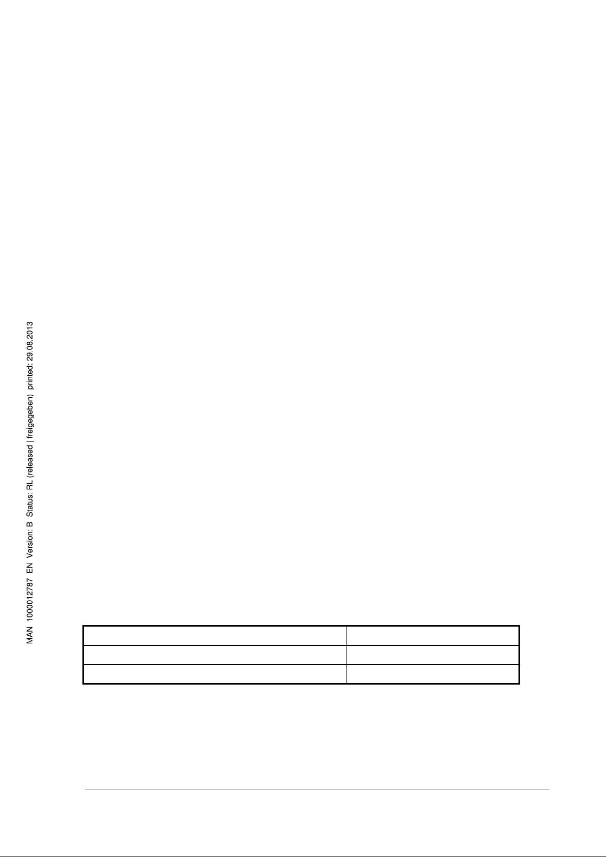
External dimension of housing ( W x H x D ) 174 mm x 51 mm x 79 mm
External dimension of front panel ( W x H x D) 188 mm x 58 mm x 8 mm
Total depth of system with plug strip 87 mm
- 5 -
Page 6
Type 8660 Control Center
________________________________________________________
4. Apparatus Variations of the Control Center
The Control Center is offered in three variations, which are differentiated by the
extensiveness of the controllable capabilities:
• Control Center 1
• Control Center 2
• Control Center 3
In the following table, the controllable capabilities for each of the three Control
Centers are marked with an 'X'.
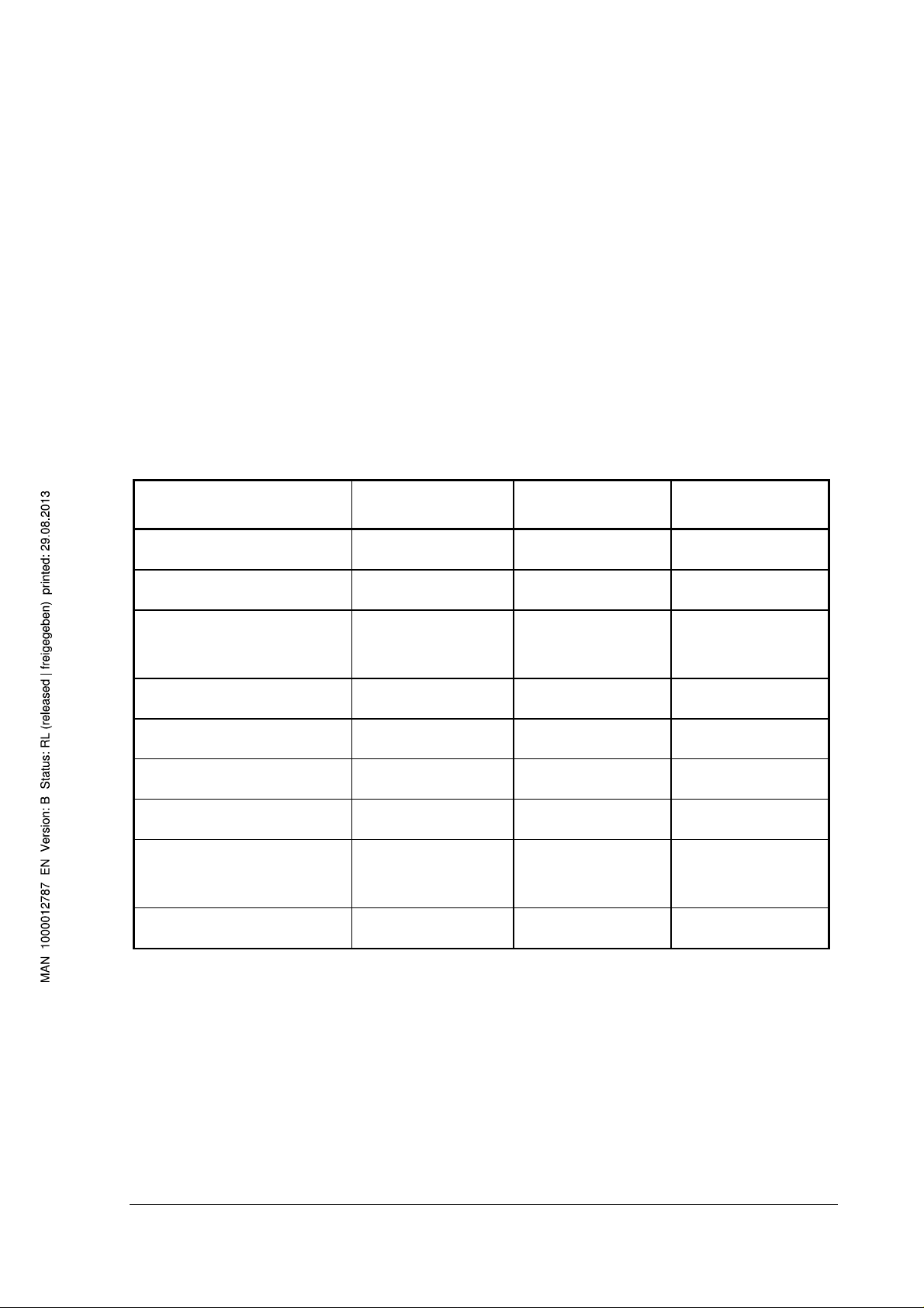
Control Center 1 Control Center 2 Control Center 3
front box flaps x x x
front box blower x x x
fresh air / circulation air
flap
driver's seat unit x
passenger area floor unit
passenger area roof unit
supplementary heater x x
supplementary water
pump
cooling unit x
x x x
x x
x x
x x
With Control Center 1, the unit in the passenger area floor can only be switched on or
off. Control Center 2 and 3 offer two switch levels.
Control Center 1 does not have a real-time clock or a time-switch for the
supplementary heater.
- 6 -
Page 7
Type 8660 Control Center
________________________________________________________
5. Connections
5.1 Wiring diagram
Plug wiring diagram for Control Center 1
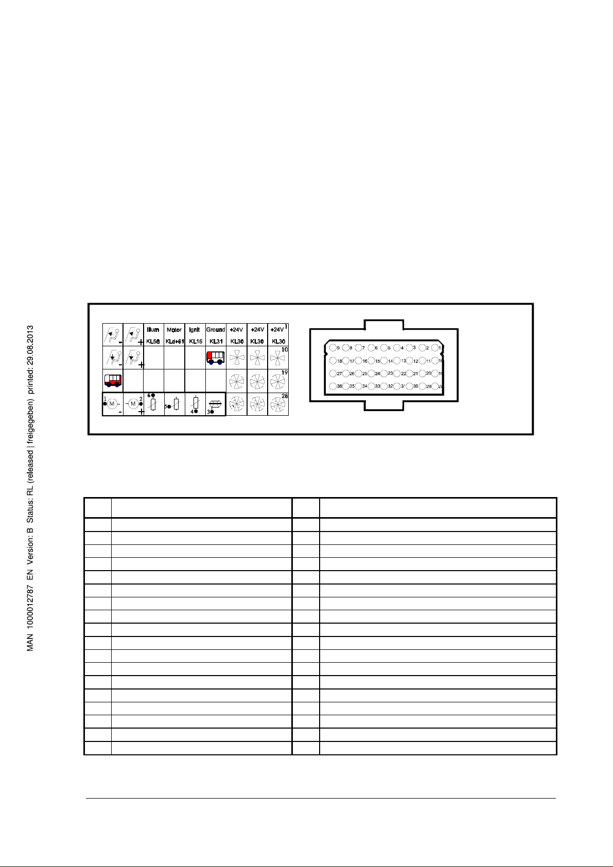
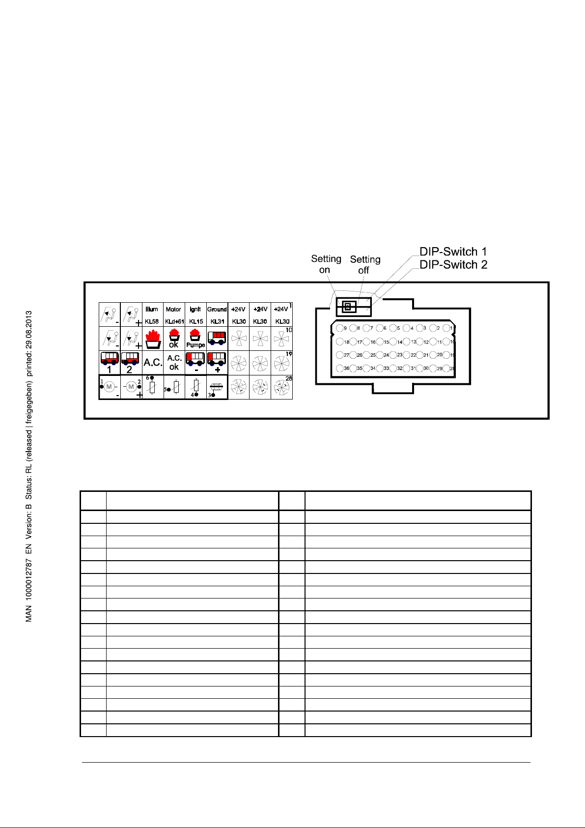
Figure 1 shows the backside of Control Center 1 with the plug area (right) and the
symbol list for the pins (left). The plug holds pins 1 to 36. The symbols for the
individual pins correspond fully with the symbols on the operating elements (see
Figure 7 and Figure 8). For further clarification, the plug wiring diagram is described
again in words in Figure 2.
Figure 1: Backside of Control Center 1 (Cannon/ITT plug)
Pin Connection Pin Connection
1 24 V 19 front box blower level 2
2 24 V 20 front box blower level 2
3 24 V 21 front box blower level 2
4 ground 22
5 ignition on (terminal 15) 23
6 motor on (terminal d+61) 24
7 illumination (terminal 58) 25
front box flaps windshield
8
front box flaps windshield
9
10 front box blower level 1 28 front box blower lever 3
11 front box blower level 1 29 front box blower lever 3
12 front box blower level 1 30 front box blower lever 3
13 driver's seat unit 31 valve potentiometer, shield
14 32 valve potentiometer, ground
15 33 valve potentiometer, sliding contact
16 34 valve potentiometer, supply +
front box flaps floor area
17
front box flaps floor area
18
26
27 passenger area floor unit
35 front box valve motor
36 front box valve motor
Figure 2: Plug wiring diagram for Control Center 1
- 7 -
Page 8
Type 8660 Control Center
________________________________________________________
Plug wiring diagram for Control Center 2 and 3
Figure 3 shows the backside of Control Center 2 and 3 with the plug (right) and the
symbol list for the pins (left). The plug holds pins 1 to 36. The symbols for the
individual pins correspond fully with the symbols on the operating elements (see
Figure 7 and Figure 8). For further clarification, the plug wiring diagram is described
again in words in Figure 4.
Figure 3: Backside of Control Center 2 and 3 (Cannon/ITT plug)
Pin Connection Pin Connection
1 24 V 19 front box blower level 2
2 24 V 20 front box blower level 2
3 24 V 21 front box blower level 2
4 ground 22 fresh air / circulation air flap +
5 ignition on (terminal 15) 23 fresh air / circulation air flap -
6 motor on (terminal d+61) 24
7 illumination (terminal 58) 25 cooling unit (only with CC 3)
front box flaps windshield
8
front box flaps windshield
9
10 front box blower level 1 28 front box blower level 3
11 front box blower level 1 29 front box blower level 3
12 front box blower level 1 30 front box blower level 3
13 passenger area roof unit 31 valve potentiometer, shield
14 supplementary water pump 32 valve potentiometer, ground
feedback Supplementary heater on
15
16 supplementary heater 34 valve potentiometer, supply +
front box flaps floor area
17
front box flaps floor area
18
feedback Cooling unit on (only with CC 3)
26 passenger area floor unit level 2
27 passenger area floor unit level 1
33 valve potentiometer, sliding contact
35 front box valve motor
36 front box valve motor
- 8 -
Page 9
Type 8660 Control Center
________________________________________________________
Figure 4: Plug wiring diagram for Control Center 2 and 3
(CC: Control Center)
Reverse polarity protection:
The supply inputs of the Control Center are permanently protected against reverse
polarity of ground and plus (up to +30 V DC).
Short circuit protection:
Terminals 35 and 36 (front box valve motor) are only protected against a short circuit
with ground, but not against a short circuit with +24 DC.
All of the other inputs and outputs of the Control Center are protected against a short
circuit with ground, as well as with plus (up to +30 V DC).
Plug wiring diagram for front box valve:
Pin Connection Color
1 valve motor
2 valve motor
3 shield
4 potentiometer, GND
5 potentiometer, sliding contact
6 potentiometer, +
Figure 5: Plug wiring diagram for front box valve (Hirschmann plugs)
- 9 -
Page 10

Type 8660 Control Center
________________________________________________________
5.2 Signal inputs
- input for feedback Ignition on Pin 5
- input for feedback Motor on Pin 6
- input for feedback Illumination on Pin 7
- input for feedback Supplementary heater on (only for Cont. Cen. 2 + 3)Pin 15
- input for feedback Cooling unit on (only for Control Center 3) Pin 24
- input for the potentiometer sliding contact connection
of the front box valve Pin 33
5.3 Signal outputs
Signal outputs for Control Center 1
- output signal for the control of the front box flaps windshield Pin 8, 9
(max. 0.5 A)
- output signal for the control of the front box flaps floor area Pin 17, 18
(max. 0.5 A)
- output signal for the control of the front box blower level 1 Pin 10, 11, 12
(max. 15 A)
- output signal for the control of the front box blower level 2 Pin 19, 20, 21
(max. 15 A)
- output signal for the control of the front box blower level 3 Pin 28, 29, 30
(max. 15 A)
- output signal for the control of a driver's seat unit Pin 13
(max. 5 A)
- output signal for the control of the passenger area floor unit Pin 27
(max. 0.5 A)
- output signal for the control of the front box valve Pin 35, 36
(max. 0.5 A)
- 10 -
Page 11

Type 8660 Control Center
________________________________________________________
Signal outputs for Control Center 2 and 3
- output signal for the control of the front box flaps windshield Pin 8, 9
(max. 0.5 A)
- output signal for the control of the front box flaps floor area Pin 17, 18
(max. 0.5 A)
- output signal for the control of the front box blower level 1 Pin 10, 11, 12
(max. 15 A)
- output signal for the control of the front box blower level 2 Pin 19, 20, 21
(max. 15 A)
- output signal for the control of the front box blower level 3 Pin 28, 29, 30
(max. 15 A)
- output signal for the control of the passenger area roof unit Pin 13
(max. 5 A)
- output signal for the control of the supplementary water pump Pin 14
(max. 0.5 A)
- output signal for the control of the supplementary heater Pin 16
(max. 0.5 A)
- output signal for the control of the fresh air / circulation air flap Pin 22, 23
(max. 0.5 A)
- output signal for the control of the cooling units (only Control Center 3) Pin 25
(max. 0.5 A)
- output signal for the control of the passenger area floor unit, level 1 Pin 27
(max. 0.5 A)
- output signal for the control of the passenger area floor unit, level 2 Pin 26
(max. 0.5 A)
- output signal for the control of the front box valve Pin 35, 36
(max. 0.5 A)
- 11 -
Page 12
Type 8660 Control Center
________________________________________________________
5.4 DIP-switch
(only for Control Center 2 and 3)
DIP-switch 1: Presettings for the passenger area roof unit
(passenger area blower or roof blower)
Setting on: passenger area blower will be automatically switched on when
the motor is switched on, and when the motor is switched off, the
blower will also switch off. The blowers can additionally be
switched on and off with the appropriate key.
Setting off: passenger area blower will not be automatically switched on.
DIP-switch 2: Presettings for the blower level 1
Setting on: front box blower level 1 will, in Ignition off, be switched on by the
time-switch 20 min. after the supplementary heater is switched on,
and switched off again after a further 20 min.
Setting off: front box blower level 1 will not be automatically switched on.
The location of the two DIP-switches in the Control Center can be seen in Figure 3.
The DIP-switches must be set before connecting to the power supply.
- 12 -
Page 13

Type 8660 Control Center
________________________________________________________
6. Structure of Heating and Cooling Systems and Control
Center Functions
6.1 System structure
Figure 6 shows a possible structure for the heating and cooling system of an
passenger bus.
Figure 6: A possible structure for a heating and cooling system
With the Control Center shown in Figure 6, the following units can be controlled:
- front box flaps
- front box blower
- fresh air / circulation air flap
- front box valve for driver's seat heater
- cooling unit
- supplementary heater / stationary heater
- supplementary water pump
- heat blower under the floor (passenger area floor unit)
- roof blower (passenger area roof unit)
- 13 -
Page 14

Type 8660 Control Center
________________________________________________________
6.2 Functions
Heating operation
The cooling water which is heated by the motor of the bus has a temperature of
approximately +80 ºC. By means of a water pump in the motor and the
supplementary water pump, the heated water is directed by a motor valve with
variable flow (front box valve) from the heat exchanger in the front box over a
thermostat controlled valve, to the heaters in the floor and roof areas.
The temperature in the front box area can be controlled by the motor valve. Under
the direction of a position regulator, the valve setting will be adjusted based on the
preset temperature set point.
Ventilation operation
The desired blower lever for the ventilation of the front box area can be set with the
middle knob (rotary switch). Blower lever 1 is already usable when the ignition is
switched on. Blower levels 2 and 3 can only be switched on when the motor is
running. With the front box flaps, the air direction can be directed toward the
windshield, toward the driver (foot area), or toward both. The unit in the passenger
area can be separately switched in Ignition on, Motor off and Motor on.
- 14 -
Page 15

Type 8660 Control Center
________________________________________________________
Cooling operation
Air which is directed into the front box area can be cooled by the cooling unit, when
the motor is running. It must be noted that only a constant cooling performance can
be achieved when the cooling unit is switched on. The amount of cooled air that is
sent into the front box area can be adjusted with the front box blower levels.
Additionally, the temperature of the air which is blown in can be variably controlled
through counter heating with the heat exchanger (corresponding operation of the set
point regulator).
When the windshield is steamed up because of high humidity, it can also be quickly
cleared by switching the cooling unit on. At the same time, a suitable level of counter
heating should be used, and the air should be directed towards the windshield, using
the left knob.
Defrosting
The setting, Defrost of the set point regulator is responsible for clearing steam and
ice from the windshield. The maximum temperature will be automatically set, the air
will be directed to the windshield, and the front box blower will be switched on - the
blower level will depend upon the current operational mode of the passenger bus
(with Ignition off: blower off; with Ignition on and motor off: blower level 1; with
Ignition on and motor on: blower level 3).
- 15 -
Page 16

Type 8660 Control Center
________________________________________________________
7. Operating the Control Center
7.1 Operating and display elements
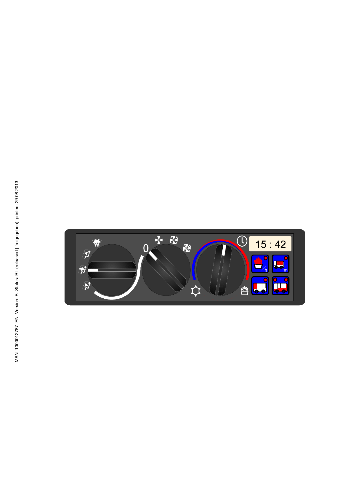
Figure 7: Operating and display elements of the Control Center
On the front panel (Figure 7), there are three rotatable knobs (two rotary switches
and one rotary potentiometer), a display (digital) and four keys.
The left knob is used to adjust the air flow direction and to choose the collective
function Defrost. It locks into each respective position. With the middle knob, the
front box blower can be set to the respective provided levels. This knob also locks
into the respective positions.
The right knob acts as the set point regulator, for the variable setting of the
temperature set point for the driver's seat heater. With this knob, the cooling unit can
also be switched on and off, and the display of the current time and the switch time
for the supplementary heater can be activated.
In the upper right corner is the display, which, when it is activated with the set point
regulation knob, shows the current time, or the switch-time for the supplementary
heater, as well as - when the occasion arises - error messages.
The four keys are located below the display. In the keys are light-emitting diodes
(LED), through which feedback for the chosen switch activity can be seen. When a
display is illuminated, the corresponding unit is switched on. With certain operating
functions, the LEDs will blink to show which keys can be used for operation (for
example, setting the time).
The definition of the operating elements is summarized in Figure 8.
- 16 -
Page 17

Type 8660 Control Center
________________________________________________________
Figure 8: Definition of the operating elements
- 17 -
(CC – Control Center)
Page 18

Type 8660 Control Center
________________________________________________________
7.2 Operating Options in Operational Mode Ignition off (ZA)
7.2.1 Overview of operating options in ZA
In the operational mode Ignition off, depending on which apparatus variation is used (Control Center 1,
2 or 3), the following operating options can be executed:
• Displaying the weekday and the time (only with Control Center 2 and 3).
The real-time clock continues to run when the ignition is off.
• Setting the real-time clock (only with Control Center 2 and 3).
• Displaying the time-switch day and the switch time, when the supplementary heater is to be
switched on (only with Control Center 2 and 3).
The time-switch clock continues to run when the ignition is off.
• Setting and activating the time-switch so that the supplementary heater switches on automatically
(only with Control Center 2 and 3).
The supplementary heater can be switched on in this way, for a maximum of 1 hour from the set
switch time. With the DIP-switch 2 (see paragraph 5.2), the user can choose ahead of time if, at
the same time, the blower level 1 should run along with the supplementary heater 20 min. after it
has been switched on - to run for 20 min. - or if it should not.
• Switching the supplementary heater on and off by pressing a key.
The supplementary water pump is then automatically switched on, and the front box valve is fully
opened. After an hour, the supplementary heater will automatically switch itself off.
• Changing the air flow direction by means of the front box flaps.
• Activating the Defrost function (without blower).
• Switching the fresh air / circulation air flap on and off with the corresponding key, or when the
supplementary heater automatically switches on.
• Activating the set point regulator for the driver's seat heater.
- 18 -
Page 19

Type 8660 Control Center
________________________________________________________
7.2.2 Setting the real-time clock in ZA
(only with Control Center 2 and 3)
When the system is in operational mode Ignition off (ZA) and the Temperature set point knob is turned
to the clock symbol (Figure 9), the weekday will be represented on the display with the digits 1
(Monday) to 7 (Sunday), interchanging (1.5 sec. / 1.5 sec.) with the time. The light-emitting diodes
(LED) in the key (hour key) and (minute key) blink. This means that these two keys can now
be used for defined operating functions (setting mode Weekday). By pressing the hour-key once
or repeatedly, the weekday can be set. If, after 10 seconds no further input is made, or if the
Temperature set point knob is rotated away from the symbol , then the setting mode Weekday will
be exited. The display will clear, and the LED’s in the keys and will no longer blink.
Figure 9: Diagram for the setting of the real-time clock
(1: Monday, ..., 7: Sunday)
- 19 -
Page 20

Type 8660 Control Center
________________________________________________________
If however, in the setting mode Weekday, the hour and minute keys ( , ) are simultaneously
pressed, the system will switch into the setting mode Time (hour and minutes). The LED’s in the keys
and blink. This means that when the keys are now pressed once or repeatedly, the hour or the
minutes can be set.
If the keys and are simultaneously pressed, the system will return to the setting mode
Weekday. If after 10 seconds no further input is made, or if the Temperature set point knob is rotated
away from the symbol , then the setting mode Time will be exited and the system returns to its
starting position. The display will clear and the LED’s in the keys and will no longer blink.
With the exiting of the setting mode Weekday or the setting mode Time, the changes which have been
made to the weekday or the time will be saved and active.
7.2.3 Setting the time-switch for the supplementary heater in
ZA
(only with Control Center 2 and 3)
When the system is in operational mode Ignition off (ZA) and the Temperature set point knob is turned
to the symbol (supplementary heater) (Figure 10), the time-switch day will be represented on the
display with the digits 1 (Monday) to 7 (Sunday) as well as the condition (on, 'oFF') interchanging (1.5 /
0.5 sec.) with the switch time. The time-switch day which will be shown first will be the next day after
the current weekday.
The display 'on' means the time-switch for the corresponding day is activated. The display 'oFF'
means that the time-switch is not activated. Additionally, the LED’s in the key and (hour or
minute key) will blink.
A further setting of the switch time is possible with the hour key . By pressing the minute key ,
Time-switch active (on) and Time-switch not active (oFF) can be toggled. If after 10 seconds no
further input is made, or if the Temperature set point knob is rotated away from the symbol , then
the setting mode Day and Condition of the time-switch will be exited. The display will clear and the
LED’s in the keys and will no longer blink.
If however, in the setting mode Day and Condition of the time-switch the hour and the minute keys
( , ) are simultaneously pressed, the system will switch into
- 20 -
Page 21

Type 8660 Control Center
________________________________________________________
the setting mode Switch time (hours and minutes). The LED’s in the keys and blink. This
means that when these keys or are now pressed once or repeatedly, the hour or the minutes
when the supplementary heater should be switched on can be set. If the keys and are
simultaneously pressed, the system will return to the setting mode Day and Condition of the time-
switch. If however, after 10 seconds no further input is made, or if the Temperature set point knob is
rotated away from the symbol , then the setting mode Switch Time will be exited. The display will
clear and the LED’s in the keys and will no longer blink.
Figure 10: Diagram for the setting of the time-switch
(1: Monday, ..., 7: Sunday)
- 21 -
Page 22

Type 8660 Control Center
________________________________________________________
With the exiting of the setting mode Day and Condition of the time-switch, or the setting mode Switch
time, the changes which have been made to the time-switch day or the switch time will be saved and
active. When at least one time-switch day is active (on), the symbol next to the Temperature set
point knob will be illuminated.
After the supplementary heater has been switched on once by the time-switch, the condition of the
corresponding time-switch day will be changed from 'on' to the condition 'oFF'. In this way, the timeswitch can be programmed for a maximum of 7 days.
7.2.4 Changing the air flow direction in ZA
The air flow direction can be changed by adjusting the Air flow direction knob. When the knob is
pointed to the symbol for Air flow direction to windshield, Air flow direction to windshield and to driver
or Air flow direction to driver, the air flow will be conducted in the corresponding direction.
7.2.5 Switching the Defrost function on and off in ZA
The Defrost function will be switched on, when the Air flow direction knob is turned to the symbol
(Defrost). In the operational mode Ignition off, this function automatically includes the directing of the
air flow direction to the windshield and the opening of the front box valves. The Front box blower knob
and Temperature set point knob have no functions, when the Front box flaps knob is in this position.
7.2.6 Changing the temperature set point in ZA
In operational mode Ignition off, the temperature set point can be changed by adjusting the
temperature set point regulator. The front box valve will be accordingly adjusted, depending on the
setting of the temperature set point regulator.
- 22 -
Page 23

Type 8660 Control Center
________________________________________________________
7.2.7 Switching the supplementary heater on and off in ZA
(only with Control Center 2 and 3)
The supplementary heater can be switched on or off, in operational mode Ignition off, by pressing the
key , or over the time-switch. When the key is used to switch it on, initially a blinking light will
show that the supplementary heater has been addressed by the Control Center. Illumination means
that the supplementary heater is switched on. If within the first 60 seconds no feedback is registered
from the supplementary heater, the LED will clear. This means that the supplementary heater would
not allow itself to be switched on. A special error message will not be shown, in this case.
When the supplementary heater is switched on, in operational mode Ignition off, the front box valve
will be fully opened and the supplementary water pump will be switched on. The fresh air / circulation
air flap goes into the Circulation position.
DIP-switch 2 can be set so that, each time the supplementary heater is switched on over the timeswitch, blower level 1 will be switched on 20 min. after the supplementary heater was switched on,
and will run along with the supplementary heater for a further 20 min. before it is again switched off
(see paragraph 5.2).
Whether the supplementary heater is switched on with the key, or for automatic operation by the timeswitch, the maximum time that it can be switched on is one hour.
If the supplementary heater was switched on in operational mode Ignition off with the key or by
the time-switch, it will automatically be switched off when the system is switched to the operational
mode Ignition on, Motor off.
7.2.8 Switching the fresh air / circulation air flap on and off in ZA
(only with Control Center 2 and 3)
Pressing the key causes the motor of the fresh air / circulation air flap to run for 60 seconds. If the
LED in the key is lit up, the flap is in the Circulation position. If the LED is switched off, the flap is in
the Fresh air position.
7.3 Operating Options in Operational Mode Ignition on and
Motor off (ZE)
- 23 -
Page 24

Type 8660 Control Center
________________________________________________________
7.3.1 Overview of the possible operating options in ZE
In the operational mode Ignition on and Motor off, depending on which apparatus variation is used
(Control Center 1, 2 or 3), the following operating options can be executed:
• Activating the front box flap to change the air flow direction
• Activating the set point regulator for the driver's seat heater
• Switching level 1 of the front box blower on and off
• Activating the Defrost function (with blower level 1)
• Switching the supplementary heater on and off by hand (only with Control Center 2 and 3). The
supplementary heater can only be switched on when the supplementary water pump is running when the valve position is > 15%. When the valve position is < 10%, it will be automatically
switched off.
• Switching the fresh air / circulation air flap on and off (only with Control Center 2 and 3)
7.3.2 Changing the air flow direction in ZE
The air flow direction can be changed by adjusting the Air flow direction knob. When the knob is
pointed to the symbol for Air flow to windshield, Air flow to windshield and to driver or Air flow to driver,
the air flow will be directed in the corresponding direction.
7.3.3 Switching the Defrost function on and off in ZE
The Defrost function will be switched on when the Front box flaps knob is turned to the symbol
(Defrost). This function, a collective function, automatically directs the air flow to the windshield,
opens the front box valve, and switches the front box blower to level 1. The Front box blower knob
and Temperature set point knob have no functions, when the Front box flaps knob is in this position.
- 24 -
Page 25

Type 8660 Control Center
________________________________________________________
7.3.4 Switching level 1 of the front box blower on and off in ZE
When the Front box blower knob is adjusted in operational mode Ignition on and Motor off, only blower
level 1 can be switched on or off. If the set point regulator points to the symbol 0, then the blower is
switched off; if it points to the symbol for level 1, 2 or 3, then blower level 1 is switched on.
7.3.5 Changing the temperature set point in ZE
In operational mode Ignition on and Motor off, it is possible to change the temperature set point by
adjusting the temperature set point regulator. The front box valve will be accordingly adjusted,
depending on the setting of the temperature set point regulator. The supplementary water pump
switches itself on automatically when the valve position is greater than 15% and switches off again
when the valve position is less than 10%.
7.3.6 Switching the supplementary heater on and off in ZE
(only with Control Center 2 and 3)
In operational mode Ignition on and Motor off, the supplementary heater can only be switched on and
off by pressing the key , not with the time-switch. It can only be switched on when the position of
the front box valve is greater than 15%. When the valve position is less than 10%, the supplementary
heater will be automatically switched off.
Feedback concerning the condition of the supplementary heater is indicated by the light-emitting diode
in the key . When it blinks, the supplementary heater has been contacted by the Control Center.
Illumination means that the supplementary heater is switched on. If within the first 60 seconds no
feedback is registered from the supplementary heater, the LED will clear. This means that the
supplementary heater would not allow itself to be switched on. A special error message will not be
shown, in this case.
If the supplementary heater was switched on in operational mode Ignition on and Motor off with the
key , it will automatically be switched off when the system is switched to the operational mode
Ignition off.
- 25 -
Page 26

Type 8660 Control Center
________________________________________________________
7.3.7 Switching the fresh air / circulation air flap on and off in ZE
(only with Control Center 2 and 3)
Pressing the key causes the motor of the fresh air / circulation air flap to run for 60 seconds. If the
LED in the key is lit up, the flap is in the Circulation position. If the LED is switched off, the flap is in
the Fresh air position.
7.4 Operating Options in Operational Mode Motor on (ME)
7.4.1 Overview of the operating options in ME
In the operational mode Motor on, depending on which apparatus variation is used (Control Center 1,
2 or 3), the following operating options can be executed:
• Activating the front box flaps to change the air flow direction
• Activating the set point regulator for the driver's seat heater
• Switching front box blower levels 1, 2 and 3 on and off
• Activating the Defrost function (with blower level 3)
• Switching the passenger area floor unit on and off (with Control Center 2 and 3 two heat levels)
• Switching the passenger area roof unit on and off (only with Control Center 2 and 3)
• Switching the supplementary heater on and off by hand (only with Control Center 2 and 3).
The supplementary heater can only be switched on when the supplementary water pump is
running - when the valve position is > 15%. When the valve position is < 10%, it will be
automatically switched off.
• Switching the driver's seat unit (with Control Center 1) or the fresh air / circulation air flap (with
Control Center 2 and 3) on and off
• Switching the cooling unit on and off (only with Control Center 3)
- 26 -
Page 27

Type 8660 Control Center
________________________________________________________
7.4.2 Changing the air flow direction in ME
The air flow direction can be changed by adjusting the Air flow direction knob. When the knob is
pointed to the symbol for Air flow to windshield, Air flow to windshield and to driver or Air flow to driver,
the air flow will be directed in the corresponding direction.
7.4.3 Switching the Defrost function on and off in ME
The Defrost function will be switched on when the Air flow direction knob is turned to the symbol
(Defrost). This function, a collective function, automatically directs the air flow to the windshield,
opens the front box valve, and, in operational mode Motor on, switches the front box blower to level 3.
The Front box blower knob and Temperature knob have no functions, when the Air flow direction knob
is in this position.
7.4.4 Switching the front box blower on and off in ME
When the Front box blower knob is adjusted in operational mode Motor on, the blower levels can be
switched between levels 0, 1, 2 and 3. The blower level which the knob is pointing to, is the blower
level which is switched on.
7.4.5 Changing the temperature set point in ME
The temperature set point can be changed by adjusting the temperature set point regulator. The front
box valve will be accordingly adjusted, depending on the setting of temperature set point regulator.
The water pump for the supplementary heater switches itself on automatically when the valve position
is greater than 15% and switches off again when the valve position is less than 10%.
- 27 -
Page 28

Type 8660 Control Center
________________________________________________________
7.4.6 Switching the supplementary heater on and off in ME
(only with Control Center 2 and 3)
In operational mode Motor on, the supplementary heater can only be switched on and off by pressing
the key . It can only be switched on when the position of the front box valve is greater than 15%.
When the valve position is less than 10%, the supplementary heater will be automatically switched off.
Feedback concerning the condition of the supplementary heater is indicated by the light-emitting diode
in the key . When it blinks, the supplementary heater has been contacted by the Control Center.
Illumination means that the supplementary heater is switched on. If within the first 60 seconds no
feedback is registered from the supplementary heater, the LED will clear. This means that the
supplementary heater would not allow itself to be switched on. A special error message will not be
shown, in this case.
7.4.7 Switching the driver's seat unit on and off in ME
(only with Control Center 1)
Pressing the key switches the driver's seat unit (for example, supplementary blower,
supplementary heating circuit) on and off. Feedback is indicated by the light-emitting diode in the key.
Illumination means that the output has power. Light-emitting diode off means that the output has no
power.
7.4.8 Switching the fresh air / circulation air flap on and off in ME
(only with Control Center 2 and 3)
Pressing the key causes the motor of the fresh air / circulation air flap to run for 60 seconds. If the
LED in the key is lit up, the flap is in the Circulation position. If the LED is switched off, the flap is in
the Fresh air position.
- 28 -
Page 29

Type 8660 Control Center
________________________________________________________
7.4.9 Switching the passenger area floor unit on and off in ME
Operation for Control Center 1:
With Control Center 1, the passenger area floor unit can only be switched on or off using the key.
The LED in the key lights up, when the unit is switched on.
Operation for Control Center 2 and 3:
By pressing the key , levels 0 (off), 1 and 2 of the passenger area floor unit can be switched.
Feedback is shown by the two light-emitting diodes in the key . When level 1 is switched on, the
right light-emitting diode is illuminated; when level 2 is switched on, both light-emitting diodes are
illuminated.
7.4.10 Switching the passenger area roof unit on and off in ME
(only with Control Center 2 and 3)
The usability of the passenger area roof unit depends upon the setting of DIP-switch 1 (see paragraph
5.2). When DIP-switch is set to 'off', the passenger area roof unit (for example, roof blower) can be
switched on or off by pressing the key . Feedback regarding the switch condition is shown by the
light-emitting diode in the key. Illumination means that the unit is switched on.
If however, DIP-switch 1 is set to 'on', then the passenger area roof unit will be automatically switched
on when the motor is switched on, and switched off when the motor is switched off.
- 29 -
Page 30

Type 8660 Control Center
________________________________________________________
7.4.11 Switching the cooling unit on and off in ME
(only with Control Center 3)
At the position which is furthest to the left of the temperature set point regulator is the switch to turn
the cooling unit on and off. Locking the switch in and then out again, switches the unit on. Feedback
is shown on the display. When AC blinks there, it means that the cooling unit has been contacted by
the Control Center. If AC is shown, but it's not blinking, then the cooling unit is switched on. To switch
the cooling unit off, lock the switch in and out once again. If no feedback is registered from the cooling
unit within the first 60 seconds, then the corresponding Control Center output will be deactivated. A
special error message will not appear.
When the motor is switched off, the cooling unit will be automatically out of operation.
- 30 -
Page 31

Type 8660 Control Center
________________________________________________________
8. Valve Check
When the power supply is connected for the first time, the Control Center runs a lengthy valve check,
to read through the end positions. In the process, the valve will be opened during a time span of 70
seconds, then closed 70 seconds. A check will also be made to make sure that a pre-defined opening
angle is exceeded.
The display during the valve check: test.
During the valve check, the supplementary heater and the cooling unit cannot be used (the
corresponding operating elements will have no functions).
9. Error messages
When the Control Center is in operation, two error messages can appear on the display.
9.1 Error message 1 (Err 1)
Display:
Err 1 blinks on the display, alternating with Vent.
While the error message appears on the display, the light-emitting diode of the Supplementary
heater/hour key will blink. This key is used to quit the error message. Pressing the key will clear the
display and stop the blinking of the light-emitting diode, and further operational activity is possible.
The error message will not be saved, and will appear only when the corresponding unit is contacted.
Possible causes:
The wires for the valve motor or the wires for the potentiometer feedback message are interchanged.
Possible operational activity:
Quit the error message by pressing the Supplementary heater/hour key. A dot on the display will
show that the message has been quitted.
Consequence
Control of the valve position is possible, even with this error. The apparatus works with default values.
9.2 Error message 2 (Err 2)
Display:
Err 2 blinks on the display, alternating with Vent.
While the error message appears on the display, the light-emitting diode of the Supplementary
- 31 -
Page 32

Type 8660 Control Center
________________________________________________________
heater/hour key will blink. This key is used to quit the error message. Pressing the key will clear the
display and stop the blinking of the light-emitting diode, and further operational activity is possible.
The error message will not be saved, and will appear only when the corresponding unit is contacted.
Possible causes:
- Drive power supply interrupted.
- Potentiometer feedback interrupted.
- Motor of the drive is defect.
- Valve is mechanically stuck.
Possible operational activity:
Quit the error message by pressing the Supplementary heater/hour key. A dot on the display will
show that the message has been quitted.
Consequence:
Depending on the temperature set point w, end positions will be assumed
(w < 50%: closed; w > 50%: open).
- 32 -
Page 33

Type 8660 Control Center
________________________________________________________
10. Maintenance and Care
10.1 Maintenance
The Control Center is maintenance-free. If disturbances occur, which are not caused by incorrect
operation, and are not handled in Chapter 8, the unit must be sent back to the supplier.
10.2 Care
The front panel may be occasionally wiped with a moist cloth, with perhaps a mild soapy solution.
Detergents and chemical solvents may not be used.
- 33 -
Page 34

Type 8660 Control Center
________________________________________________________
11. Technical Data
11.1 Electrical Data
Operation sizes
Pin number Operational mode Power consumption
1,2,3 (+24 V) ignition off (standby operation) < 50 mA
1,2,3 (+24 V) ignition on, motor off < 100 mA
1,2,3 (+24 V) ignition on, motor on < 200 mA
1,2,3 (+24 V) all outputs switched on < 20 A
5 (ignition on) maximum power consumption < 100 mA
6 (lighting circuit) maximum power consumption < 100 mA
7 (illumination) maximum power consumption < 200 mA
Reverse polarity protection
The supply inputs of the Control Centers are permanently protected against
reverse polarity of ground and plus.
Electromagnetic compatibility EMC
Resistance to disturbances: meets ISO/DP 7637/2
Radiation measurement: meets DIN 40839
CE symbol
The Control Center has a CE-conformity symbol for all three variations.
11.2 Mechanical Data
Weight 0.4 kg
Storage temperature -40...+120 ºC
Operation temperature -25...+85 ºC
The front panel is built to withstand water spray.
- 34 -
Page 35

Type 8660 Control Center
________________________________________________________
Appendix 1: Flow Chart for Setting the Real-time Clock
Notes
Ø It is only possible to set the real-time clock in operational mode Ignition off.
Ø The weekdays are represented by 1 (Monday) to 7 (Sunday).
Ø All changes which are made to the time and weekday are active as soon as the setting mode is
exited.
- 35 -
Page 36

Type 8660 Control Center
________________________________________________________
Appendix 2: Flow Chart for Setting the Time-Switch
Notes
Ø It is only possible to set the real-time clock in operational mode Ignition off.
Ø The time-switch days are represented by 1 (Monday) to 7 (Sunday).
Ø When the setting mode Day and Condition of the time-switch is active, the time-switch day which
is first shown will be the day following the current weekday.
Ø All changes which are made to the switch time and time-switch day are active as soon as the
corresponding setting mode is exited.
Ø After the supplementary heater has been switched on by the time-switch, the condition of the
corresponding time-switch day changes from on to oFF.
Ø The time-switch can be programmed for a maximum of the next 7 days.
- 36 -
Page 37

Bürkert Company Locations
Contact addresses / Kontaktadressen
Germany / Deutschland / Allemange
Bürkert Fluid Control System
Sales Centre
Chr.-Bürkert-Str. 13-17
D-74653 Ingelfingen
Tel. + 49 (0) 7940 - 10 91 111
Fax + 49 (0) 7940 - 10 91 448
E-mail: info@de.buerkert.com
International
Contact addresses can be found on the internet at:
Die Kontaktadressen finden Sie im Internet unter:
Les adresses se trouvent sur internet sous :
www.burkert.com
 Loading...