

Page 1
Operating Instructions
Bedienungsanleitung
Instructions de Service
Type 8630
TOP Control Continuous
Page 2

We reserve the right to make technical changes without notice.
Technische Änderungen vorbehalten.
Sous resérve de modification techniques.
© 2001 Bürkert Werke GmbH & Co KG.
Operating Instructions 0507/11_EU-EN_00804575
Page 3

Overall Operating Instructions
C
ONTENTS
TOP Control
Continuous 8630
GENERAL NOTES
Symbols.......................................................................................................................................................................................................................................................... 10
Intended use ............................................................................................................................................................................................................................................ 10
Safety notes .............................................................................................................................................................................................................................................. 10
Protection from damage by electrostatic charging ......................................................................................................................... 11
Scope of delivery .............................................................................................................................................................................................................................. 11
Warranty conditions ...................................................................................................................................................................................................................... 11
Master code .............................................................................................................................................................................................................................................. 12
Transport, storage ............................................................................................................................................................................................................................ 12
Disposal ......................................................................................................................................................................................................................................................... 12
SYSTEM DESCRIPTION
Valve types................................................................................................................................................................................................................................................. 14
Characteristics of the valve types
Construction of TOP Control Continuous ..................................................................................................................................................... 16
Illustrations (cover removed)
Design features
Functional diagram as a positioner with single-acting actuator
..................................................................................................................................................................................................................................... 17
Operation as a positioner ..................................................................................................................................................................................................... 19
Schematic representation of positioning control
Characteristics of the positioner software
...................................................................................................................................................................................... 15
................................................................................................................................................................................................... 16
............................................................................................................ 18
.................................................................................................................................................. 20
.................................................................................................................................................................. 21
*
Alternative chapters or functions depending on device configuration
8630 - 1
Page 4

C
ONTENTS
*Operation as a process controller (option)............................................................................................................................................... 22
Example of process control: TOP Control Continuous with sensor
Schematic representation of process control
Characteristics of the process controller software
......................................................................................................................................................... 23
............................................................................................................................................. 24
................................................................................................... 22
* Operation as a flow rate controller (option).......................................................................................................................................... 25
Characteristics of the flow rate controller software
Schematic representation of process control with flow rate controller
......................................................................................................................................... 25
....................................................................................... 26
* Interfaces of the TOP Control Continuous in the multipole variant .................................................................. 27
* Interfaces of the TOP Control Continuous in the variants with
cable bushings
.................................................................................................................................................................................................................................. 28
Technical data........................................................................................................................................................................................................................................ 29
Safety settings on failure of auxiliary electrical or pneumatic energy
Factory settings on the TOP Control Continuous
Data of the TOP Control Continuous
............................................................................................................................................................................. 31
............................................................................................................................................. 30
......................................................................................... 29
FIRST COMMISSIONING
Fluidic installation............................................................................................................................................................................................................................. 34
*Electrical installation - multipole connector ............................................................................................................................................ 35
*Electrical installation - connection terminals for cable bushings............................................................................ 36
Basic settings of the TOP Control Continuous..................................................................................................................................... 37
Settings in the menu items
Entering the position setpoint in the AUTOMATIC mode
Manual opening and closing of the valve actuator in the MANUAL mode
....................................................................................................................................................................................................... 38
.......................................................................................................................... 38
............................................................................. 39
INSTALLATION
Installation of the valve ............................................................................................................................................................................................................ 42
Turning the TOP Control Continuous.................................................................................................................................................................. 42
Procedure
................................................................................................................................................................................................................................................... 42
Fluidic connection of the TOP Control Continuous....................................................................................................................... 43
*
Alternative chapters or functions depending on device configuration
2 - 8630
Page 5

C
ONTENTS
*Electrical connection - multipole connectors ....................................................................................................................................... 44
Marking of the multipole plugs or sockets and the contacts
Output signals for SPS (circular plug M 16)
Operating voltage (circular plug M 12)
Inductive proximity switches (circular socket M 8)
Process value (circular plug M 8)
....................................................................................................................................................................................... 46
............................................................................................................................................................. 45
............................................................................................................................................................................ 45
........................................................................................................................................... 45
Process value with the option flow rate controller (2 circular plugs M 8)
Option: with temperature sensor input (3 circular plugs M 8)
................................................................................................................... 44
.............................................................................................................. 46
*Electrical connection - terminals for cable bushing.................................................................................................................... 47
Connection PCB of the TOP Control Continuous with screw terminals and jumpers ................................................ 47
Terminal configuration with cable bushings
Choice of binary outputs or process value input
............................................................................................................................................................ 47
............................................................................................................................................... 48
*Setting the inductive proximity switches (option)........................................................................................................................... 50
Opening the housing of the TOP Control Continuous
Positioning the inductive proximity switches
.......................................................................................................................................................... 50
................................................................................................................................. 50
OPERATION AND CONTROLLER FUNCTIONS
Operating and display elements ................................................................................................................................................................................ 52
Operating levels.................................................................................................................................................................................................................................. 52
Commissioning and set-up as a positioner............................................................................................................................................... 53
Procedure for specifying the basic settings
Main menu for the settings on commissioning
Description of the procedure
.................................................................................................................................................................................................. 55
Configuring the supplementary functions .................................................................................................................................................... 59
Keys in the configuration level
Configuration menu
.......................................................................................................................................................................................................................... 59
Supplementary functions
.............................................................................................................................................................................................. 59
........................................................................................................................................................................................................... 62
Operating the process............................................................................................................................................................................................................... 86
Changeover between operating modes
Operating mode AUTOMATIC....................................................................................................................................................................................... 87
Meaning of the keys in the AUTOMATIC mode
Display of the AUTOMATIC mode
..................................................................................................................................................................................... 87
............................................................................................................................................................ 53
.................................................................................................................................................... 54
...................................................................................................................................................................... 86
.................................................................................................................................................. 87
Operating mode MANUAL.................................................................................................................................................................................................. 88
Meaning of the keys in the MANUAL mode
Display of the MANUAL mode
*
Alternative chapters or functions depending on device configuration
.............................................................................................................................................................................................. 88
............................................................................................................................................................ 88
8630 - 3
Page 6

C
ONTENTS
OPERATING THE PROCESS CONTROLLER
Factory settings on the process controller................................................................................................................................................... 90
Setting up a process control system .................................................................................................................................................................... 90
Self-parametrization of the positioner -
Supplementary function
Basic settings of the function
P.Q’LIN
P.CO TUNE -
P.CO LEAK -
- Starting the routine for linearization of the process curve ..................................................................... 105
Display during call-up and execution of the routine
Self-optimization of the process controller (process tune) ..................................................... 106
Leakage characteristic for flow rate control ................................................................................................... 110
P.CONTRL
P.CONTRL
X.TUNE
.................................................................................................................................................................... 91
................................................................................................................................................................... 92
............................................................................................................................... 91
.......................................................................................................................................... 105
Operating the process ............................................................................................................................................................................................................... 112
Changeover between the operating modes
................................................................................................................................................................ 112
Operating mode AUTOMATIC....................................................................................................................................................................................... 113
Meaning of the keys
Displays
........................................................................................................................................................................................................................................................ 113
Operating structure and procedures
......................................................................................................................................................................................................................... 113
.................................................................................................................................................................................. 113
Manually changing the process setpoint ...................................................................................................................................................... 114
Operating mode MANUAL.................................................................................................................................................................................................. 114
Meaning of the keys
Displays
........................................................................................................................................................................................................................................................ 115
Operating structure and procedures
......................................................................................................................................................................................................................... 114
.................................................................................................................................................................................. 115
PROFIBUS DP
General notes......................................................................................................................................................................................................................................... 118
Technical data ....................................................................................................................................................................................................................................... 118
Safety settings on bus failure ......................................................................................................................................................................................... 118
Interfaces....................................................................................................................................................................................................................................................... 119
Electrical connections ............................................................................................................................................................................................................... 119
Connection with one plugged bus connector
Connection with 2 plugged bus connectors
Operating voltage (circular plug M12)
Bus connection (circular socket M12)
........................................................................................................................................................... 119
.............................................................................................................................................................. 120
............................................................................................................................................................................. 120
............................................................................................................................................................................ 120
4 - 8630
Page 7

C
ONTENTS
Inductive proximity switches (circular socket M8)............................................................................................................................................. 121
Process value (circular plug M8)
Termination connection for PROFIBUS systems
......................................................................................................................................................................................... 121
................................................................................................................................................ 122
Settings on the TOP Control Continuous ..................................................................................................................................................... 123
Explanation of the menu items .............................................................................................................................................................................................. 124
Functional deviations from the standard version.............................................................................................................................. 124
Configuration in the Profibus DP master ...................................................................................................................................................... 125
Configuration of the process values
................................................................................................................................................................................. 125
Bus status display ........................................................................................................................................................................................................................... 127
Example 1 with COM-Profibus V3.3 .................................................................................................................................................................... 128
Example for a positioner
............................................................................................................................................................................................................... 128
Example 2 with COM-Profibus V3.3 .................................................................................................................................................................... 131
Example for a process controller
......................................................................................................................................................................................... 131
DEVICE NET
General notes......................................................................................................................................................................................................................................... 134
Explanation of terms .................................................................................................................................................................................................................... 134
Technical data ....................................................................................................................................................................................................................................... 135
Safety settings on bus failure ......................................................................................................................................................................................... 135
Interfaces....................................................................................................................................................................................................................................................... 136
Electrical connection................................................................................................................................................................................................................... 136
Operating voltage (4-pole M12 circular plug)
Bus connection (4-pole M12 circular plug)
Inductive proximity switches (4-pole M8 circular socket)
Process value (circular plug M8)
......................................................................................................................................................................................... 137
Termination connection for DeviceNet systems
Net topology of a DeviceNet system
............................................................................................................................................................................... 138
Settings on the TOP Control Continuous ..................................................................................................................................................... 139
Explanation of the menu items in the program run-off schematic
Settings in the main menu
......................................................................................................................................................................................................... 140
........................................................................................................................................................... 137
................................................................................................................................................................. 137
........................................................................................................................... 137
................................................................................................................................................... 138
...................................................................................................... 139
Configuring the process data ......................................................................................................................................................................................... 141
Static input assemblies
Static output assemblies
................................................................................................................................................................................................................. 141
............................................................................................................................................................................................................. 143
8630 - 5
Page 8

C
ONTENTS
Bus status display ........................................................................................................................................................................................................................... 144
Configuration example 1 ....................................................................................................................................................................................................... 145
Installation of the EDS file
Address allocation
Offline parametrization of the device
Online parametrization of the device
.............................................................................................................................................................................................................................. 145
......................................................................................................................................................................................................... 145
............................................................................................................................................................................... 146
............................................................................................................................................................................... 147
Configuration example 2 ....................................................................................................................................................................................................... 148
Setting up the process map (mapping)
.......................................................................................................................................................................... 149
MAINTENANCE AND ERROR CORRECTION ON THE POSITIONER
Maintenance ............................................................................................................................................................................................................................................ 152
Error messages and malfunctions .......................................................................................................................................................................... 152
Error messages on the LC display
Other malfunctions
............................................................................................................................................................................................................................. 152
..................................................................................................................................................................................... 152
MAINTENANCE AND ERROR CORRETION ON THE
PROCESS CONTROLLER
Maintenance ............................................................................................................................................................................................................................................ 154
Error messages and malfunctions .......................................................................................................................................................................... 154
Error messages on the LC display
Other malfunctions
............................................................................................................................................................................................................................. 156
..................................................................................................................................................................................... 154
Appendix
6 - 8630
Page 9

C
ONTENTS
GENERAL RULES
Selection criteria for continuous valves .......................................................................................................................................................... 158
Characteristics of PID controllers............................................................................................................................................................................. 160
P component
I component
D component
Superimposing the P, I and D components
Function of a real PID controller
Rules for setting PID controllers ................................................................................................................................................................................ 165
Setting rules of Ziegler and Nichols (oscillation method)
Setting rules of Chien, Hrones and Reswick (controller output step method)
............................................................................................................................................................................................................................................ 160
.............................................................................................................................................................................................................................................. 161
............................................................................................................................................................................................................................................ 162
............................................................................................................................................................... 163
........................................................................................................................................................................................... 164
............................................................................................................................ 165
........................................................................ 166
OPERATING STRUCTURE
Operating structure of the TOP Control Continuous..................................................................................................................... 170
TABLE FOR POSITIONER
Table for noting your settings on the positioner .................................................................................................................................. 178
TABLE FOR PROCESS CONTROLLER
Tables for noting your settings on the process controller ..................................................................................................... 180
MASTER CODE
Code number .......................................................................................................................................................................................................................................... 182
8630 - 7
Page 10

C
ONTENTS
8 - 8630
Page 11

G
ENERAL NOTES
GENERAL NOTES
Symbols.............................................................................................................................................................................................................................................................. 10
Intended use
Safety notes
Protection from damage by electrostatic charging
Scope of delivery
Warranty conditions
................................................................................................................................................................................................................................................ 10
.................................................................................................................................................................................................................................................. 10
............................................................................................................................. 11
.................................................................................................................................................................................................................................. 11
.......................................................................................................................................................................................................................... 11
Master code .................................................................................................................................................................................................................................................. 12
Transport, storage
................................................................................................................................................................................................................................ 12
Disposal ............................................................................................................................................................................................................................................................. 12
8630 - 9
Page 12

GENERAL NOTES
Symbols
The following symbols are used in these operating instructions:
marks a work step that you must carry out.
ATTENTION!
NOTE
Intended use
In order for the device to function perfectly and have a long service life, you must observe the information
given in these operating instructions and comply with the operating conditions and the permissible data
for the TOP Control Continuous, in addition to the information for the respective pneumatically actuated
valve, which is specified in the „Technical Data“ chapter of these instructions and in the valve
instructions.
Please note that the Top control Continuous may not be used out-of-doors.
In view of the large number of possible applications and categories of use, you should check whether the
Top control Continuous is suitable for your specific application, and carry out tests where necessary.
Safety notes
marks notes on whose non-observance your health or the functioning of the device
will be endangered.
marks important additional information, tips and recommendations.
• Keep to standard engineering rules in planning the use of and operating the device!
• Installation and maintenance work are only allowed by specialist personnel using suitable tools!
• Observe the current regulations on accident prevention and safety during operation and maintenance
of the device!
• Switch off the supply voltage in all cases before intervening in the system!
• Note that in systems under pressure, piping and valves may not be loosened!
• Take suitable precautions to prevent inadvertent operation or damage by unauthorized action!
• Make sure that after an interruption to the electrical or pneumatic supply, the process starts up again in
a well-defined, controlled manner!
• On non-observance of these notes and unauthorized interference with the device, we will refuse all
liability and the warranty on device and accessories will become void!
10 - 8630
Page 13

Protection from damage by electrostatic charging
This device contains electronic components that are sensitive to
electrostatic discharge (ESD). Contact to electrostatically charged
persons or objects will endanger these components. In the worst
case, they will be immediately destroyed or will fail after
commissioning.
GENERAL NOTES
ATTENTION
EXERCISE CAUTION ON HANDLING!
ELECTROSTATICALLY SENSITITVE
COMPONENTS/MODULES
Observe the requirements of EN 100 015 - 1 in order to minimize
the possibility of, or avoid, damage from instantaneous electrostatic
discharge. Also take care not to touch components that are under
supply voltage.
Scope of delivery
Immediately after receipt of a shipment, make sure that the contents are undamaged and match the
scope of delivery stated on the packing slip. In general this consists of:
• Pneumatically actuated valve of type 2652, 2655, 2672, 2700, 2712, 2730, 2731 or 2731K with attached
TOP Control
• Operating Instructions for the TOP Control
If there are discrepancies, please contact immediately our customer service:
Continuous,
Continuous and for the valve with pneumatic actuation.
Bürkert Fluid Control Systems
Chr.-Bürkert-Str. 13-17
Service Department
D-76453 Ingelfingen
Tel.: (07940) 10-111
Fax: (07940) 10-448
E-Mail: info@de.buerkert.com
NOTE
Suitable cable plugs for the multipole connection are available as accessoires.
Warranty conditions
This document contains no warranty promises. We refer in this connection to our General Conditions of
Sale and Business. The condition for the warranty is use of the unit for the intended purpose under the
specified application conditions.
ATTENTION!
The warranty covers only faultless condition of the TOP Control Continuous and the
attached valve with pneumatic actuation. No liability will be accepted for consequential
damage of any kind that may arise from failure or malfunctioning of the device.
8630 - 11
Page 14
GENERAL NOTES
Master Code
Operation of this device can be locked by means of a freely selectable user code. Independent of this,
there exists an unchangeable master code with which you can execute all operative actions on the
device. This 4-digit code is to found on the last page of these operating instructions.
If required, cut out this code and keep it separate from these operating instructions.
Transport, storage
ATTENTION!
Transport and store the appliance in its original packing only.
Disposal
ATTENTION!
When disponsing of the appliance, observe the national standards for refuse disposal.
12 - 8630
Page 15

SYSTEM DESCRIPTION
SYSTEM DESCRIPTION
Valve types ................................................................................................................................................................................................................................................ 14
Characteristics of the valve types .......................................................................................................................................................................... 15
Construction of TOP Control Continuous.................................................................................................................................................... 16
Illustrations (cover removed) ........................................................................................................................................................................................ 16
Design features
Functional diagram as a positioner with single-acting actuator
.............................................................................................................................................................................................................................. 17
....................................................................................... 18
Operation as a positioner.................................................................................................................................................................................................... 19
Schematic representation of positioning control ................................................................................................................................. 20
Characteristics of the positioner software
................................................................................................................................................... 21
* Operation as a process controller (option) .......................................................................................................................................... 22
Example of process control: TOP Control Continuous with sensor ............................................................................ 22
Schematic representation of process control
Characteristics of the process controller software
.......................................................................................................................................... 23
............................................................................................................................ 24
* Operation as a flow rate controller (option)......................................................................................................................................... 25
Characteristics of the flow rate controller software.......................................................................................................................... 25
Schematic representation of process control with flow rate controller
................................................................... 26
* Interfaces of the TOP Control Continuous in the multipole variant ................................................................. 27
* Interfaces of the TOP Control Continuous in the variants with cable bushings ........................... 28
Technical data
Safety settings on failure of auxiliary electrical or pneumatic energy ...................................................................... 29
Factory settings on the TOP Control Continuous
Data of the TOP Control Continuous
* Alternative chapters or functions depending on device configuration
....................................................................................................................................................................................................................................... 29
............................................................................................................................... 30
.................................................................................................................................................................. 31
8630 - 13
Page 16
SYSTEM DESCRIPTION
By the combination of the TOP Control with pneumatically actuated process valves, the functionality of
the Bürkert process valve series is extended. These valves, in connection with the TOP Control, may
also be employed in those control applications requiring continuous behaviour of the actuator.
Valve types
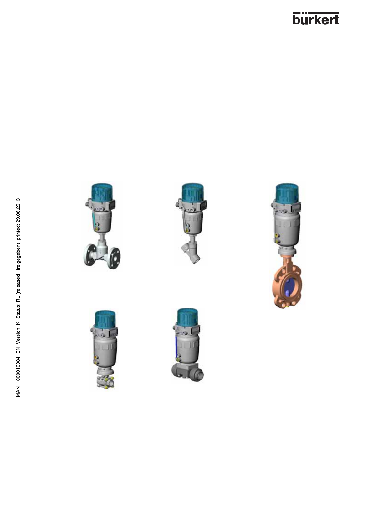
The figure below gives an overview of the possible combinations of TOP Control and various
pneumatically actuated valves. For each type, various actuator sizes and valve sizes are available (not
shown). More detailled information is to be found on the respective data sheets. The product range is
being extended continually.
TOP Control
Continuous
Type 8630
with flat-seat valve
Type 2712
(here with flange connection)
TOP Control
Continuous
Type 8630
with ball valve
Type 2655
with Y-valve Type 2700
with butterfly valve
Type 2672
with diaphragm valve
Type 2730
Various process valves from the Bürkert range can be combined with the TOP Control to suit different
applications. Y-, diaphragm or ball valves with control cones are suitable.
14 - 8630
Page 17
SYSTEM DESCRIPTION
Pneumatically driven piston and rotary actuators may be used to operate them. Both single-acting and doubleacting actuators are offered in combination with TOP Control Continuous.
With single-acting actuators, only one chamber in the actuator is pressurized and vented. The pressure
produced works against a spring. The piston moves until an equilibrium is set up between the pressure and the
spring force.
With double-acting actuators, the chambers on both sides of the piston are pressurized. When the one
chamber is pressurized, the other is vented and vice versa. No spring is installed in this actuator version.
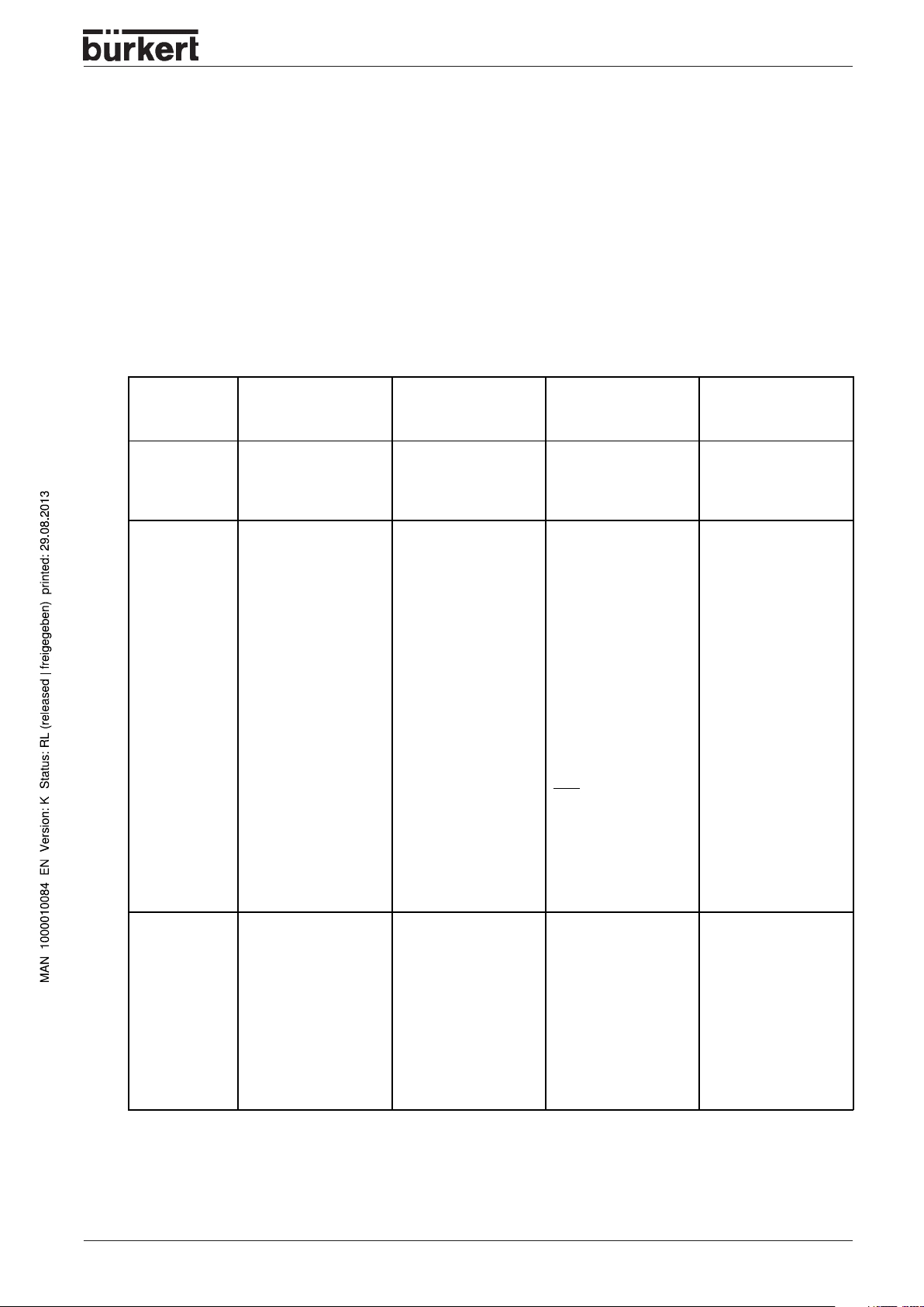
Characteristics of the valve types
Typ es
Characteristic
Y-valves
Flat seat valves
• 2700
• 2712
• Inlet flow under seat
• Non-impact closure
• Straight flow of
medium
• Self-adjusting packed
gland for very tight seal
Diaphram valves Ball valves Flap valves
• 2730 (plastic)
• 2731 (metal)
• 2731K (pipe housing)
• Medium is hermeti cally separated from
actuator and the
ambient
• Self-draining housing
design without dead
spaces
• Either flow direction
with low turbulence
flow
• May be steam
sterilized
• CIP compatible
• Non-impact closure
• Actuator and dia phragm are de tachable with the
housing
• 2652 (2-part,VA)
• 2655 (3-part,VA)
• 2658 (plastic)
• Piggable
• Low and dead space
• insensitive to
contamination
• Lower pressure loss
than with other valve
types
• with 3-part ball valve,
seat and seal can be
exchaged while
installed
Note
Only usable as process
controller.
• 2672 (metal)
• 2675 (plastic)
• insusceptible to dirt
• less pressure loss
compared to other
valve types
• good value for money
• smaller volume
Typ ica l me dia
• Water, steam and
gases
• Alcohols, oils, fuels,
hydraulic fluides
• Salt solutions, lyes
(organic)
• Organic solvents
• Neutral gases and
liquids
• contaminated, ab rasive and aggressive
media
• high purity or sterile
media
• high viscosity media
• Neutral gases and
liquids
• pure water
• slightly aggressive
media
• Neutral gases and
fluides
• slightly aggressive
media
8630 - 15
Page 18
SYSTEM DESCRIPTION
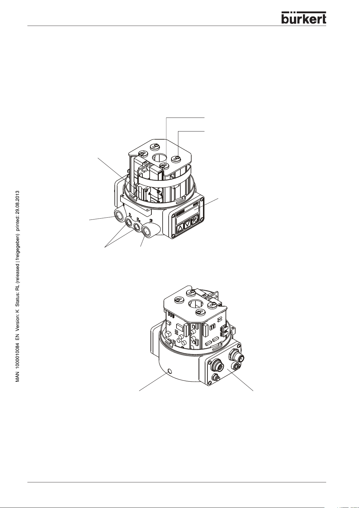
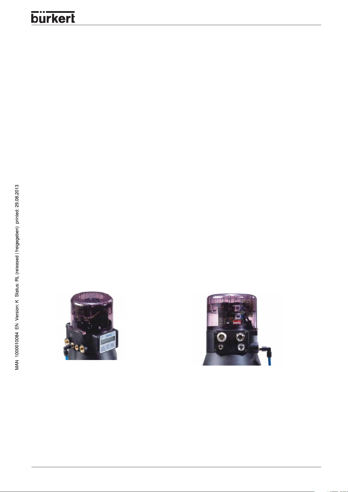
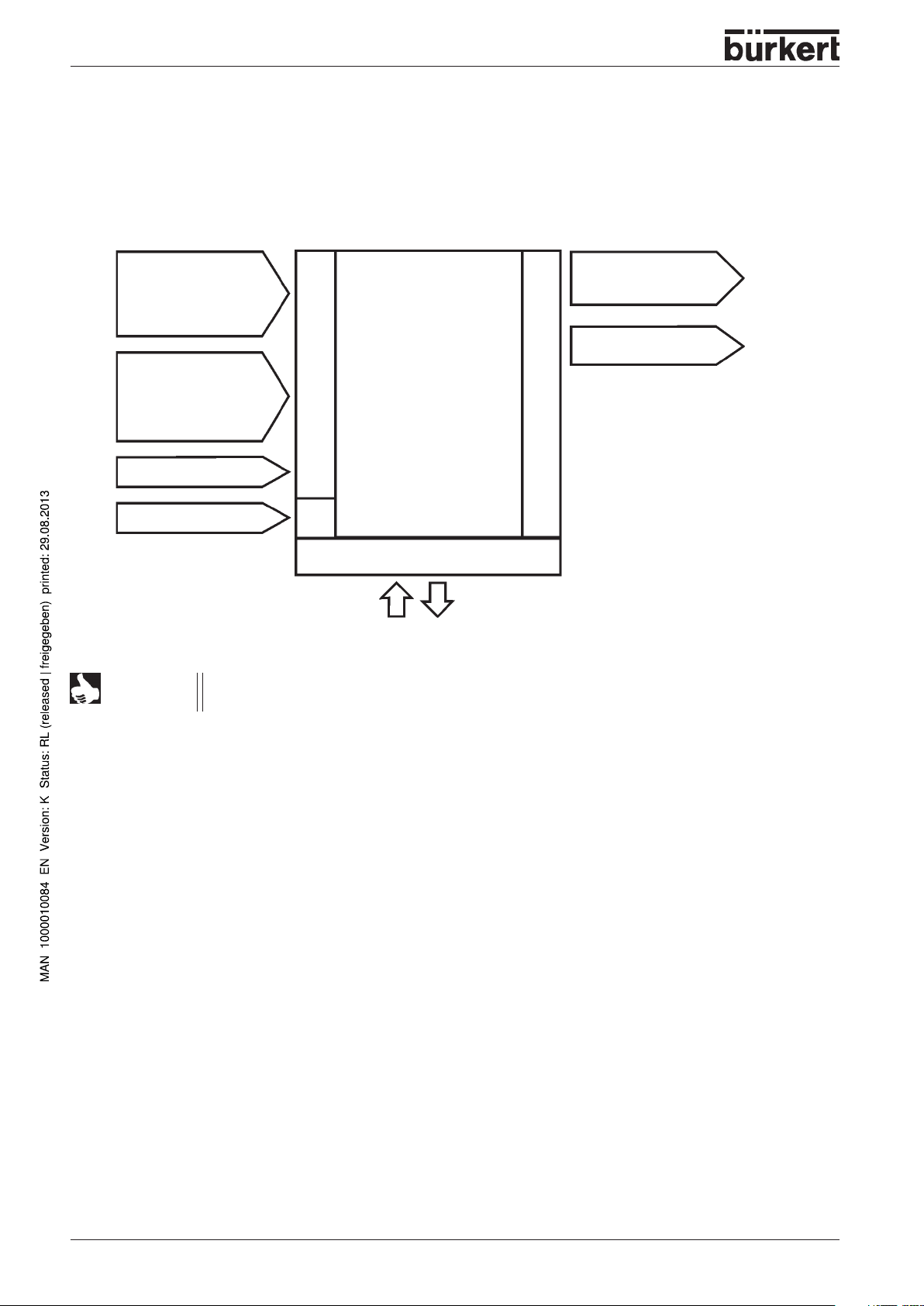
Construction of TOP Control Continuous
Illustrations (cover removed)
Positioning system
with 2, 3 or 4 solenoid valves
Screw for adjusting the lower proximity
switch
Screw for adjusting the upper proximity
switch
Pressure supply port
(marked: 1)
Control ports
(connected in the
factory)
Operating module with display and
keys
Exhaust air ports
(marked 3)
16 - 8630
Fixing screw for fixing the
TOP Control Continuous
on the drive
Max. torque 1.2 Nm
Electrical connection module,
here with multipole connectors
Page 19
Design features
•
Versions
for single and double acting valve actuators
Position sensor
•
very high resolution conductive plastic potentiometer, coupled without play to the piston rod of the
pneumatic actuator
Microprocessor controlled electronics
•
for signal processing, control and driving the valve
Operating module
•
The device is operated via 3 keys. 8-digit, 16-segment LC display for showing the setpoint or actual
value and for configuration and parametrization via menu functions.
Positioning system
•
With single-acting actuators, the positioning system consists of 2 solenoid valves; with double-acting
actuators of four solenoid valves. With single-acting actuators, one valve serves to pressurize the
pneumatic piston drive and another to exhaust it. Double-acting actuators contain 2 valves for
pressurization and 2 for exhausting.The solenoid valves work on the rocker principle and are driven
via the controller with a PWM voltage. This enables great flexibility with regard to actuator volumes
and floating speed. For larger pneumatic actuators, the solenoid valve are equipped with diaphragm
boosters.
SYSTEM DESCRIPTION
As an option, with single-acting actuators, there are fast pressurizing/exhaust variants with an additional pressurizing valve and an additional exhaust valve. These enable the actuator to be completely
pressurized and exhausted more rapidly. This is used with the tight-closure function (see section
"
CUTOFF
Position repeater (optional)
•
2 inductive proximity switches (initiators) or mechanical limit switches.
Attainment of an upper or lower position of the valve can be relayed via binary outputs e.g. to a PLC.
The end settings on the initiators can be adjusted by the owner by means of setscrews.
") and on activation of a safety position of 0 or 100% (see section "
BIN-IN
").
•
Pneumatic interfaces
1/4’’- connectors in various threads
(G, NPT, RC)
•
Housing
The housing of the TOP Control is protected by a pressure relief valve from excessive internal
pressure, e.g. resulting from leaks.
The cover may be secured against unauthorized opening with a lead seal or with a self-tapping
screw.
•
Electrical interfaces
Multipole plug connector or cable bushing
8630 - 17
Page 20
SYSTEM DESCRIPTION
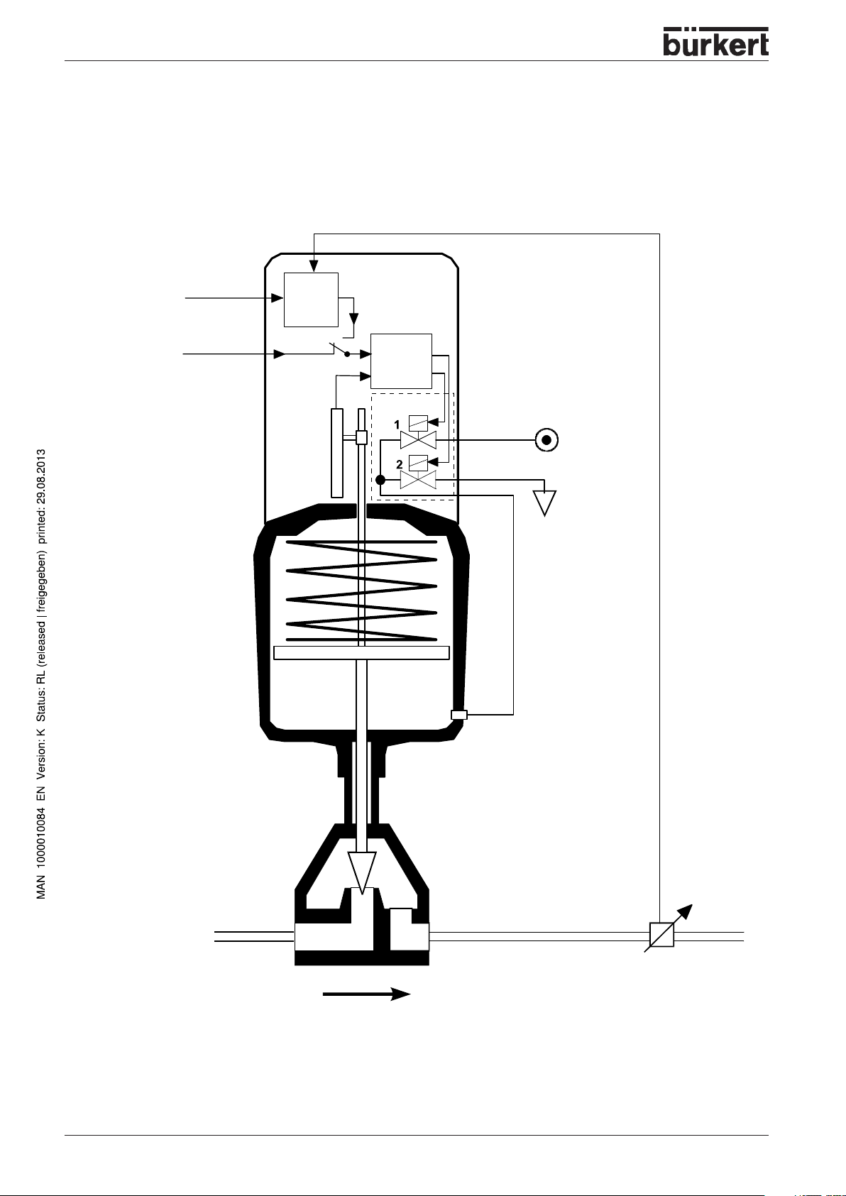
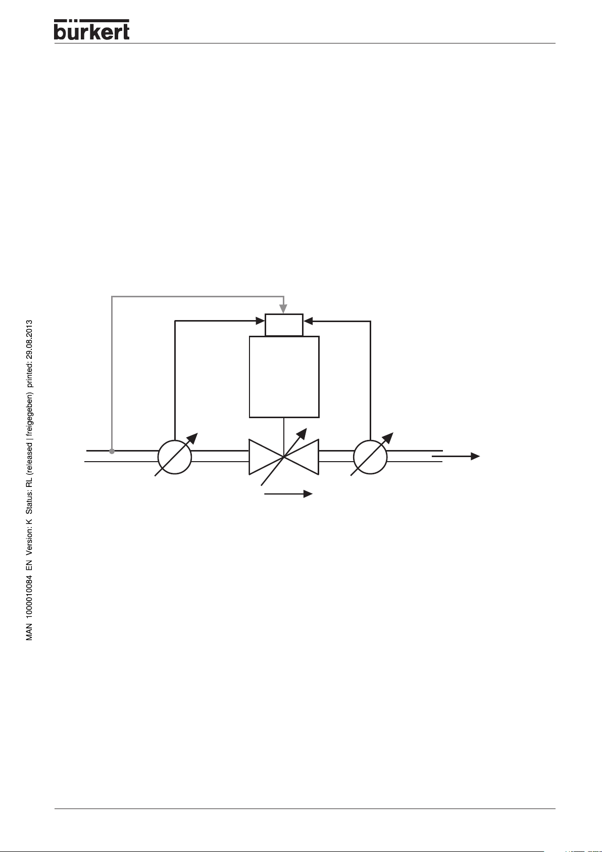
Fuctional diagram as a positioner with single-acting actuator
Actual process value
Process
setpoint
external
position
setpoint
TOP Control Continuous
Process
controller
Actual
position
Position
sensor
Setpoint position
Positioner
Positioning
system
Positioning system
1: pressurizing valve
2: exhaust valve
Compressed air
supply
Pneumatic
actuator
(single-acting)
Valve
(actuator)
Exhaust air
Sensor
18 - 8630
Actual process value
(flow rate, pressure, level,
temperature etc.)
Page 21
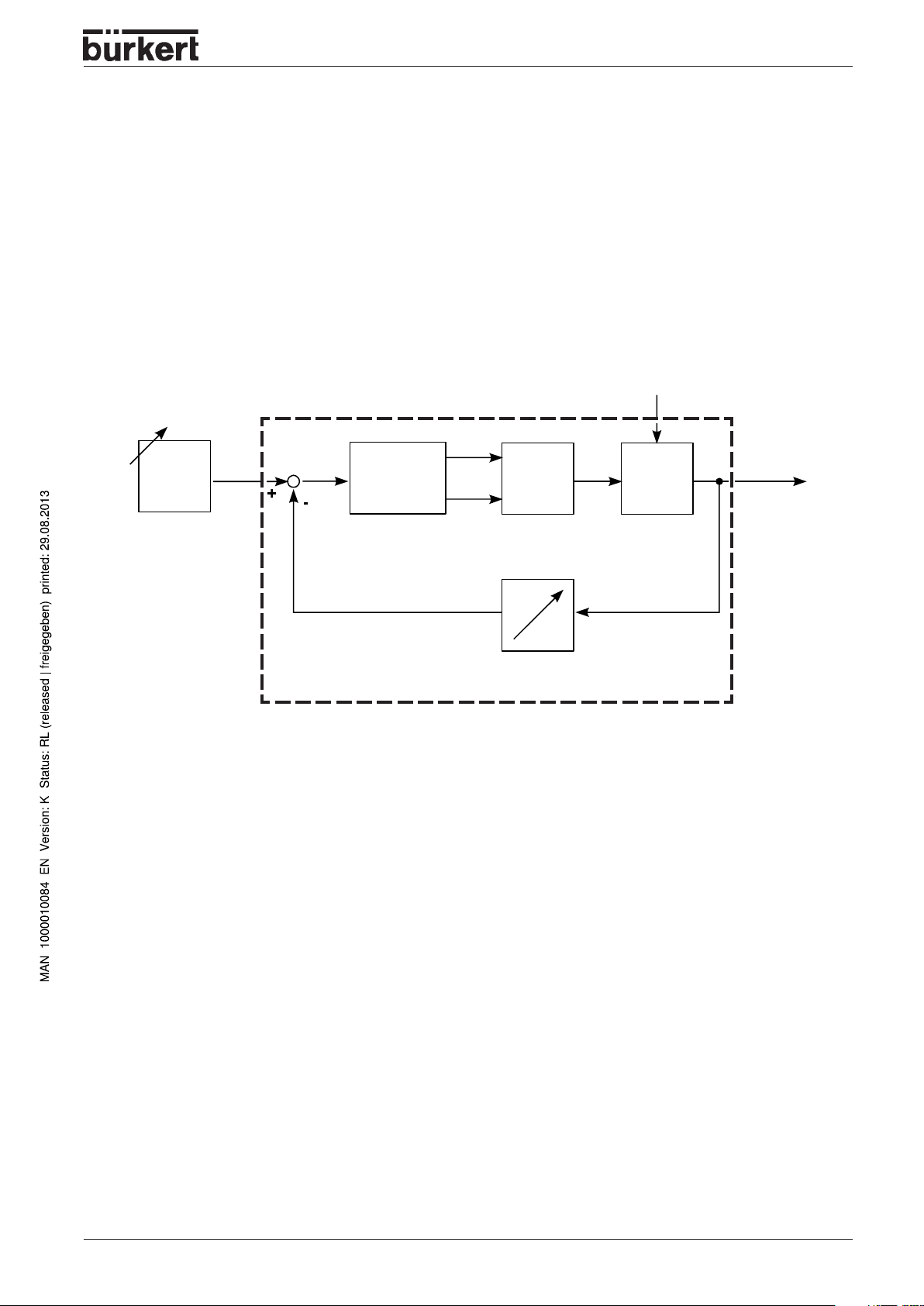
SYSTEM DESCRIPTION
Operating as a positioner
The actual position (POS) of the pneumatic actuator is measured via the position sensing system. The
controller compares this actual value of the position with the setpoint (CMD) , which can be specified as
a standard signal. If a control difference (Xd1) exists, a pulse-width modulated voltage signal is sent to
the positioning system as the correcting variable. With single-acting actuators, if the difference is positive, the pressurizing valve is driven via output B1; if it is negative, the exhaust valve is driven via output
E1. In this way, the position of the actuator is altered until the control difference is zero. Z1 represents a
disturbance.
Z1
CMD
Position setpoint Positioner
Xd1
Position control
loop
B1
E1
Positioning
system Solenoid
POS
Wegmeßsystem
Position sensor
P
K
Continious valve
Valve opening
8630 - 19
Page 22
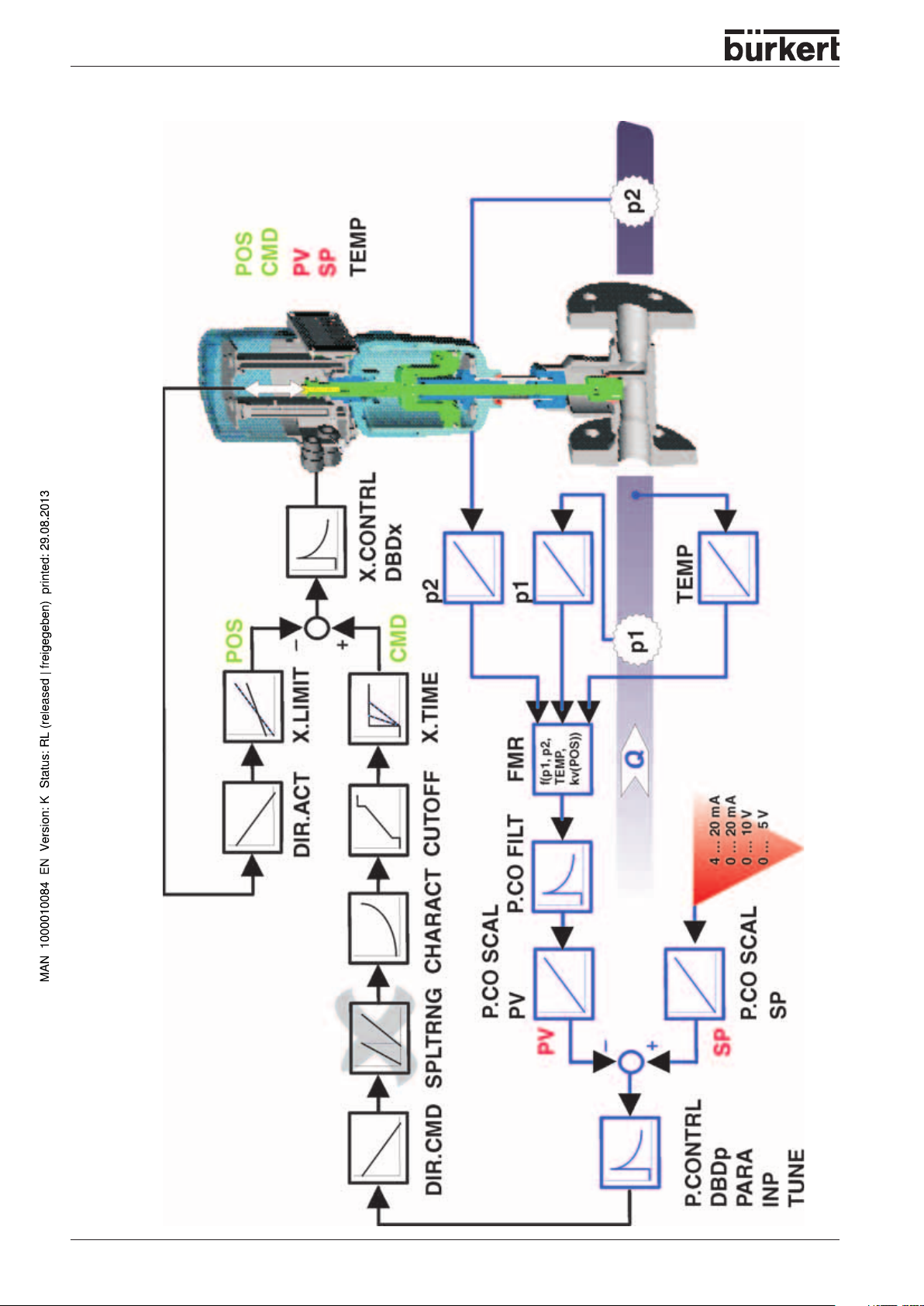
SYSTEM DESCRIPTION
POS
CMD
INP
X.CONTRL
DBDx
POS
X.LIMIT
DIR.ACT
CMD
X.TIME
CUTOFF
20 - 8630
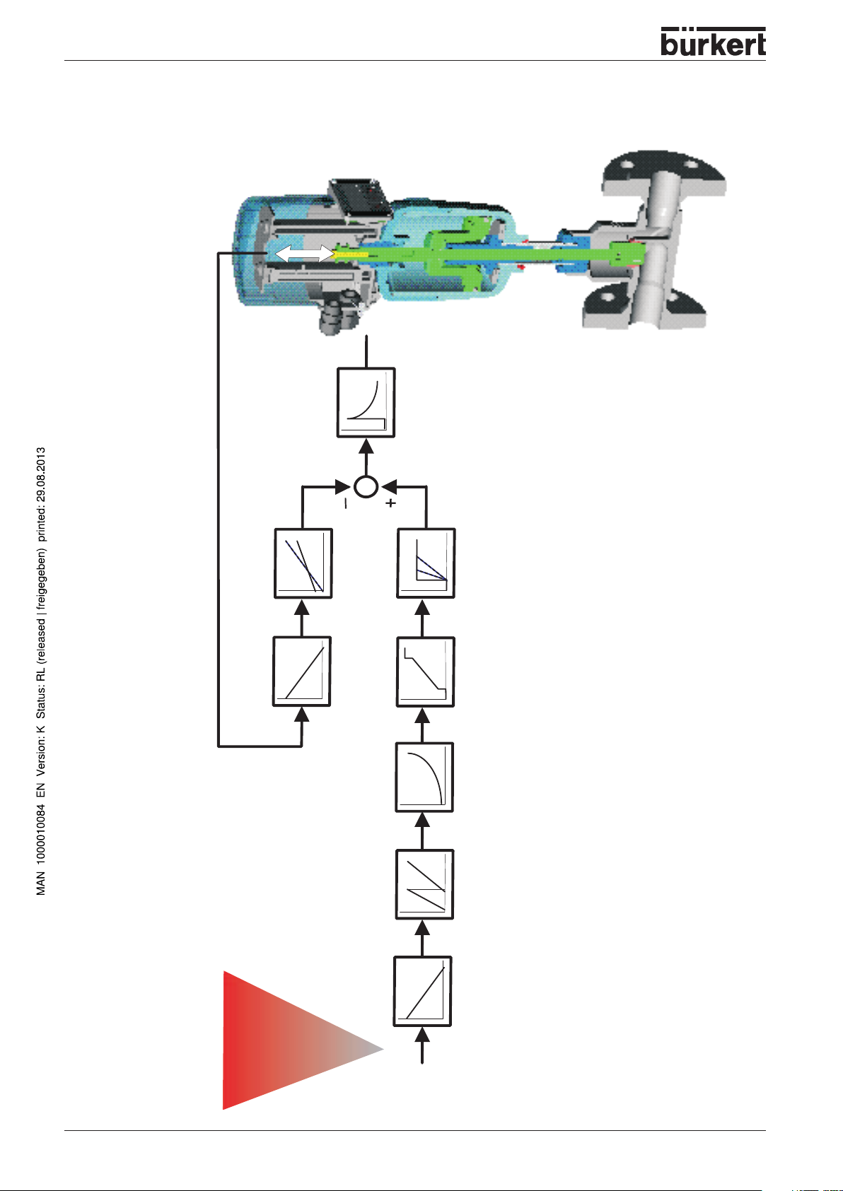
Schematic representation of positioning control
4 … 20 mA
0 … 20 mA
0 … 10 V
0 … 5 V
DIR.CMD SPLTRNG CHARACT
INP
Page 23
Characteristics of the positioner software
Supplementary function Effect
Positioner with supplementary functions
Valve closes tight outside control range. A value is
Tight-closing function
given (at %) from which the actuator is completely
exhausted (at 0%) or pressurized (at 100 %).
SYSTEM DESCRIPTION
Stroke limitation
Signal range splitting
Correction characteristic to match
the operating curve
Insensitivity range
Direction of action of the controller
setpoint
Safety position Valve moves to a specified safety position.
Hierarchical concept for simple operation with the following levels
Process operation
Configuration
Mech. valve piston movement only withhin a specified
stroke range.
Splitting of the standard signal range over two or more
TOP Control Continuous.
Linearization of the process characteristic can be
performed.
The positioner cuts in only above a specified control
difference.
Reversal of the setpoint action direction
In this level your switch between automatic and manual
operation.
In this level you specify on commissioning certain basic
functions and configure supplementary functions as
needed.
8630 - 21
Page 24
SYSTEM DESCRIPTION
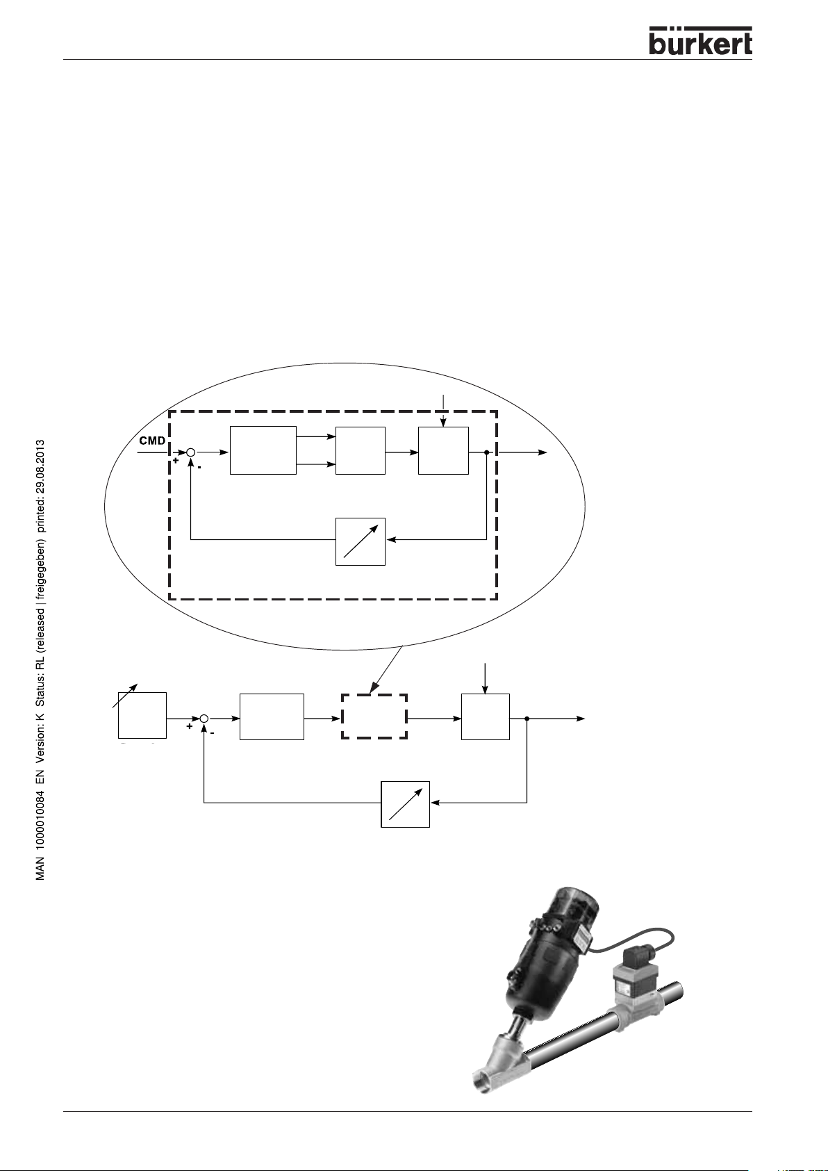
* Operation as a process controller (option)
On operation of the TOP Control Continuous as a process controller, the abovementioned position
control becomes a subordinate auxiliary control loop; the result is a cascade control. The process
controller in the main loop of the TOP Control Continuous has a PID function. The setpoint specified is
the process setpoint (SP) and it is compared with the process variable to be controlled. The actual
position (XPOS) of the pneumatic actuator is measured via the position sensing system. The controller
compares this actual value of the position with the setpoint (CMD) , which can be specified as a
standard signal. If a control difference (Xd1) exists, a pulse-width modulated voltage signal is sent to the
positioning system as the correcting variable. With single-acting actuators, if the difference is positive,
the pressurizing valve is driven via output B1. If it is negative, the exhaust valve is driven via output E1.
In this way, the position of the actuator is altered until the control difference is zero. Z2 represents a
disturbance.
Z1
Process
setpoint
Xd1
Positioner
XPOS
Position control loop
SP
Xd2
Process controller
B1
E1
Positioning
system Solenoid valves
Position sensor
Process
CMD
control
loop
PV
P
K
Continuous
Valve
Valve
opening
Valve
opening
Z2
Process variable
Process
Example of process control:
TOP Control Continuous with sensor
22 - 8630
Transmitter
Page 25
SYSTEM DESCRIPTION
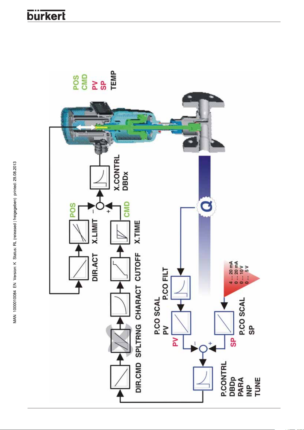
Schematic representation of process control
8630 - 23
Page 26
SYSTEM DESCRIPTION
Characteristics of the process controller software
Supplementary function Effect
Positioner with supplementary functions
Valve closes tight outside control range. A value is
Tight-closing function
Stroke limitation
Signal range splitting
Correction characteristic to match
the operating curve
Insensitivity range
Direction of action of the controller
setpoint
Safety position Valve moves to a specified safety position
Analog feedback (option)
given (at %) from which the actuator is completely
exhausted (at 0%) or pressurized (at 100%).
Mech. valve piston movement only within a specified
stroke range.
Splitting of the standard signal range over two or more
TOP Control Continuous.
Linearization of the process characteristic can be
performed.
The positioner cuts in only after a specified control
difference.
Reserval of the setpoint action direction
Feedback of the position/process values
Binary outputs
Connectable process controller with the following characteristics (Option)
Controller structure PID
Parameters that can be set
Scalable input
Method of setpoint setting Setting either via standard signal input or via keys
Hierarchical concept for simple operation with the following levels
Process operation
Configuration
Proportional action factor, reset time, rate time and
operating point
Decimal point position, upper and lower sacle valures
of process value and setpoint
In this level your switch between automatic and manual
operation.
In this level you specify on commissioning certain basic
functions and configure supplementary functions as
needed.
24 - 8630
Page 27
* Operation as a flow rate controller (option)
The flow rate controller is a special type of process controller. The process value (PV) is not measured
directly via an analog input but calculated in the device by the dp method. According to the algorithm,
the flow rate is dependent on the parameters
dium temperature
for 2 pressure transmitters and a temperature transmitter which can be optionally connected.
One pressure transmitter measures the pressure before the valve and a second one after the valve. The
temperature is either entered manually in the operating menu or is provided as a standard signal by a
temperature transmitter. The kv value is determined internally from the current position of the control
valve. For this purpose, a kv characteristic curve is provided in the control valve used.
The density of the medium is entered via the operating menu.
Temperature (optional)
(T) and the kv value. For this reason, the
pressure before valve
TOP Control Continuous FMR
SYSTEM DESCRIPTION
(p1),
pressure after valve
(p2),
me-
has inputs
Pressure
p1 p2
kv value
T
p1
In the case of the flow rate controller, the process parameters are either the volumetric flow rate or, for
special applications, the transport velocity at the end of a pumping section.
The volumetric flow rate is represented in m
gas pressure of 1013 mbar (abs).
There are special applications for flow rate controllers in which a pumping section is set up after the
valve, in which bulk goods enter via an airlock. These bulk goods are blown through the pumping
section by the pumping pressure that builds up behind the valve.
PV
8630
Flow rate
controller
e.g. valve
type 2712
3
/h STP, i.e. referred to 0 °C (medium temperature) and a
Pressure
p2
The transport velocity corresponds to the volumetric flow rate of the medium, referred to the piping
diameter of the pumping section. However, it is not specified for standard conditions, but reflects the
velocity of the gas particles at the existing medium temperature. The diameter is entered in the
operating menu.
Characteristics of the flow rate controller software
The flow rate controller offers the same functions as the process controller.
8630 - 25
Page 28
SYSTEM DESCRIPTION
Schematic representation of process control with flow rate controller
26 - 8630
Page 29
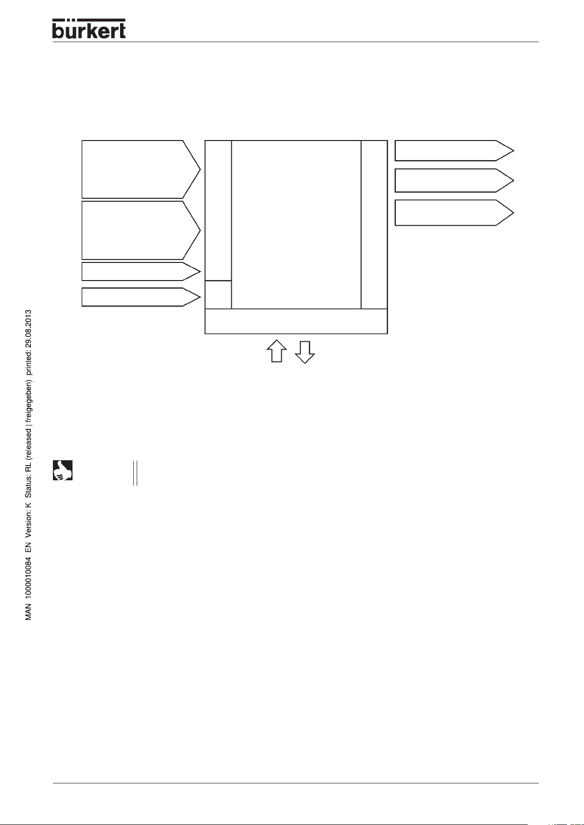
* Interfaces of the TOP Control Continuous
in the multipole variant
SYSTEM DESCRIPTION
Inputs for position or
process setpoint
4..20 mA
0..20 mA
0..10 V
0..5 V
Input for process setpoint
4..20 mA
Frequency
Pt 100
* Flow rate controller
Binary input
24 V DC
* Note:
Inputs for process value with flow rate controller (option): p1, p2, T (optional).
The standard process controller inputs (4 ... 20 mA, frequency, Pt 100) and the initiators cannot be used with this option.
Inputs
Sup-
ply
TOP Control
Continuous
(multipole - variant)
Operating unit
2 binary outputs
Analog position feedback
*Initiators 1 + 2
Outputs
NOTE
TOP Control Continuous Type 8630 is a 3-conductor device, i.e. the voltage supply (24 V
DC) is separate from the setpoint signal.
8630 - 27
Page 30
SYSTEM DESCRIPTION
* Interface of the TOP Control Continuous in the variants with
cable bushings
Inputs for position or process
setpoint
4..20 mA
0..20 mA
0..10 V
0..5 V
Input for process setpoint*
4..20 mA
Frequency
Pt 100
(alternative to binary outputs)
Binary input
24 V DC
NOTE
TOP Control Continuous Type 8630 is a 3-conductor device, i.e. the voltage supply (24 V
DC) is separate from the setpoint signal.
Inputs
Sup-
ply
TOP Control
Continuous
(PG - variant)
Operating unit
2 binary outputs*
(alternative to input for process
setpoint)
Analog
position feedback
Outputs
*
Note:
The choice between a
process setpoint input and
two binary outputs is made
by positioning the jumper.
28 - 8630
Page 31

SYSTEM DESCRIPTION
Technical data
Safety settings on failure of auxiliary electrical or pneumatic energy
Actuator type Designation Safety position after
failure of auxiliary energy
Electrical Pneumatic
Single-acting down down
SFA
Single-acting up up
SFB
Double-acting down / up undefined
SFI (depending on
connection of
control
conductors)
8630 - 29
Page 32

SYSTEM DESCRIPTION
Factory settings on the TOP Control Continuous
Function Factory setting
ACTFUNC FUNCSNGL
INPUT INP 4'20 A
CHARACT CHA LIN
DIR.CMD DIR.CRISE
CUTOFF CUT
0 %,
CUT
DIR.ACT DIR.ARISE
SPLTRNG SR
X.LIMIT LIM
0 (%),
0 %,
SR
LIM
X.TIME
T.OPN
T.CLS
After execution of
Values calculated by
Values calculated by
SETFACT:
1 s
OUTPUT
OUT ANL:
OUT POS OUT 4´20 A
OUT BIN:
OUT DEV DEV 5.0 NO
BIN-IN
B.IN SPOS SPOS 000 NO
100 %
100 (%)
100 %
AUTOTUNE
AUTOTUNE
Function Factory setting
X.CONTRL
X.CO DBND 1 %
X.CO PARA
KX
KX
After execution of
Values calculated by
Values calculated by
SETFACT:
1
P.CONTRL
P.CO DBND 1 %
P.CO PARA
KP 1.00
TN 999.9
TV 0.0
X0 0
P.CO SETP SETP INT
P.CO INP INP 4´20 A
P.CO FILT 0
P.CO SCAL PV 000.0, PV 100.0
P.CO TUNE D’ACT
P.CO KV FACT
P.CONTRL with flow rate controller
.CO DBND 1 %
P
P.CO PARA
KP 1.0
TN 999.9
TV 0.0
X0 0
P.CO SETP SETP INT
P.CO INP INP P1’P2
P.CO FILT 0
P.CO SCAL PV 000.0, PV 100.0
P.TYP FLOW
UNIT M3/H
TEMP MAN
DENS 1.293
DIAM 0025
P.CO TUNE D’ACT
P.CO KV FACT
AUTOTUNE
AUTOTUNE
NOTE
30 - 8630
CODE CODE 0000
The functions and factory settings shown in grey are valid for the optional
flow rate control.
Page 33

Data of the TOP Control Continuous
OPERATING CONDITIONS
SYSTEM DESCRIPTION
Permissible ambient temperature
Protection type
cable or plug and socket)
ATTENTION!
The TOP Control Continuous is not suitable for outdoor use.
- 10 ... + 50 °C
IP 65 to EN 60529 (only with correctly connected
CONFORMITY TO THE FOLLOWING STANDARDS
CE
conformity wer. EMC Guideline 89/336/EWG
MECHANICAL DATA
Dimensions
Housing material TOP Control
Dichtmaterial
see data sheet
outer: Noryl (PPE/PA), PSU, inner: PA 6
NBR
ELECTRICAL DATA
Connections
Choice between multipole connector or
3 bushings M 16 x 1.5
with screw terminals 0.14 ... 1.5 mm²
Voltage supply
24 V DC ± 10 %
residual ripple 10 %
No industrial DC!
Power consumption
< 5 W
Housing internal temperature
indication
Input resistance for
actual value signal
Input resistance for
setpoint signal
Protection class
- 55 ... + 125 °C, accuracy ± 2 °C
180 Ω at 4 - 20 mA/resolution 12 bit
17 kΩ at frequency, 0 ... 1000 Hz / 1‰ of mean
> 300 V
PT-100 - 20 ... + 220 °C, resolution < 0.1 °C
180 Ω at 0/4 - 20 mA/resolution 12 bit
19 kΩ at 0 - 5/10 V /resolution 12 bit
3 to VDE 0580
Analog position feedback:
max. current
for voltage output 0 ... 5/10 V 10 mA
max. burden
for current output 0/4 ... 20 mA 560 Ω
Inductive proximity switch
current limitation 100 mA
sinus, square-wave, sawtooth
ss
8630 - 31
Page 34

SYSTEM DESCRIPTION
Binary outputs
electrically isolated
current limitation 100 mA, output is clocked
Binary input
electrically isolated
0 ... 5 V = log "0", 10 ... 30 V = log "1"
inverted output reversed accordingly
PNEUMATIC DATA
Control medium Qualitiy Classes to DIN ISO 8573-1
Dust content Class 5
max. particle size 40 µm, max. particle density 10 mg/m
Water content Class 3
max.pressure dew point
- 20 °C or min. 10 deg. below the lowest operating temperature
Oil content Class 5
max. 25 mg/m³
Temperature range of
compressed air -10 ... + 50 °C
Pressure range 3 ... 7 bar
Supply pressure variation max. ± 10 % during operation
3
Air flow capacity of
control valve 100 l
/ min STP (for pressurizing and exhausting)
N
(Q
- value acc. to definition on pressure drop from 7 to 6 bar abs.)
Nn
Intrinsic air consumption
with zero control output 0.0 l
/min STP
N
Connections G 1/4’’ internal thread G / NPT / RC
32 - 8630
Page 35

FIRST COMMISSIONING
FIRST
COMMISSIONING
Fluidic installation............................................................................................................................................................................................................................ 34
* Electrical installation - multipole connector
* Electrical installation - connection terminals for cable bushings
Basic settings of the TOP Control Continuous
Settings in the menu items.............................................................................................................................................................................................. 38
Entering the position setpoint in the AUTOMATIC mode
Manual opening and closing of the valve actuator in the MANUAL mode
......................................................................................................................................... 35
........................................................................ 36
................................................................................................................................... 37
......................................................................................................... 38
......................................................... 39
* Alternative chapters or functions depending on device configuration
8630 - 33
Page 36

FIRST COMMISSIONING
NOTE
This section enable you to put the TOP Control Continuous rapidly into operation for a
functional check. Supplementary functions unnecessary for this purpose are not dealt with
here.
Fluidic installation
➔ Install the valve according to operating
instructions!
➔ Connect supply pressure to connection "1" (3
.. 7 bar; instrument air, free from oil, water
and dust)
➔ Attach the exhaust line or silencer to
connection "3"!
NOTE
Remove the protective caps from the valve and and the TOP Control
Continuous!
34 - 8630
Page 37

* Electrical installation - multipole connector
M12M16
➔ Apply the setpoint signal to the circular
connector M16
FIRST COMMISSIONING
Configuration of the circular connector M 16
Allocation
B
A
➔ Apply the supply voltage to the circular connector M12
Setpoint + (0/4 ... 20 mA
or 0 ... 5/10 V)
Setpoint GND
External connection/Signal levelPin
B
A
+ (0/4 ... 20 mA or 0 ... 5 / 10 V)
GND
Configuration of the circular connector M 12
Pin Allocation External connection
1 + 24 V
2 not connected
3 GND
4 not connected
1
24 V DC ± 10 %
max. residual ripple 10 %
3
NOTE
After application of the supply voltage, the TOP Control Continuous is in operation. Carry out the
necessary basic settings and initiate self-parametrization of the TOP Control.
Further installation notes are to be found in the chapter
Installation
.
8630 - 35
Page 38

FIRST COMMISSIONING
* Electrical installation - connection terminals for cable bushings
➔ Remove the cover with the cable bushings
to gain access to the terminals. This is done
by unscrewing the 4 self-tapping screws.
➔ Apply the setpoint signal and the supply
voltage to the respective terminals (see
Terminal configuration with cable bushings
).
screw terminals
Terminal configuration with cable bushings
Terminal Allocation External connection
1 Setpoint +
2 Setpoint GND
5 Operating voltage +
6 Operating voltage GND
1
2
5
6
+ + (0/4 ... 20 mA or 0 ... 5/10 V)
GND
24 V DC ± 10 %
max. residual ripple 10 %
NOTE
After application of the supply voltage, the TOP Control Continuous is in operation. Carry out the
necessary basic settings and initiate self-parametrization of the TOP Control.
Further installation notes are to be found in the chapter
Installation
.
36 - 8630
Page 39

Basic settings of the TOP Control Continuous
Configuration of the keys
MANUAL/AUTOMATIC-key Switch between main
and subitems,
e.g.
ACT FUNC - FUNCSNGL
Arrow keys Switch between equal-ranking
menu items,
e.g.
ACTFUNC - INPUT
AUTOMATIC
MODE
FIRST COMMISSIONING
MANUAL
MODE
Jump over on first commissioning
8630 - 37
Page 40

FIRST COMMISSIONING
Settings in the menu items
ACTFUNC
INPUT
ADDFUNCT
X.TUNE
END XX
the display
memory.
Actuator function
FUNC SNGL
FUNC DOUB
Standard signal
INP 4’20A
INP 0’20A
INP 0’10V
INP 0’5V
Jump over
Initiate self-parametrization
Return to AUTOMATIC mode
- single-acting
- double-acting
- Current 4 ... 20 mA
- Current 0 ... 20 mA
- Voltage 0 ... 10 V
- Voltage 0 ... 5 V
EEPROM
appears until the settings have been in the
;
Entering the position setpoint in the AUTOMATIC mode
After selection of the basic settings and return to the AUTOMATIC mode, the TOP Control Continuous
works as a positioner.
Enter the position setpoint via the signal.
Switching between the
display options:
Display:
• Actual position of valve actuator
• Setpoint position of valve actuator
• Input signal for setpoint position
(here identical to setpoint position) (0 ... 5/10 V or 0/4 ... 20 mA)
• Temperature inside
TOP Control Continuous housing
POS__XXX
CMD__XXX
INP__XXX
TEMP_XX.X
(0 ... 100 %)
(0 ... 100 %)
(in °C)
38 - 8630
Page 41

Manual opening and closing of the valve actuator in the
MANUAL mode
Open valve actuator:
Close valve actuator:
Display: the display set in the AUTOMATIK mode is retained.
FIRST COMMISSIONING
NOTE
Select the display
be checked.
POS_XXX
, in this case the actual position of the valve actuator can
8630 - 39
Page 42

FIRST COMMISSIONING
40 - 8630
Page 43

INSTALLATION
INSTALLATION
Installation of the valve ............................................................................................................................................................................................................ 42
Turning the TOP Control Continuous
................................................................................................................................................................. 42
Procedure ............................................................................................................................................................................................................................................... 42
Fluidic connection of the TOP Control Continuous ....................................................................................................................... 43
* Electrical connection - multipole connectors
Marking of the multipole plugs or sockets and the contacts .................................................................................................. 44
Output signals for SPS (circular plug M 16)
Operating voltage (circular plug M 12)
Inductive proximity switches (circular socket M 8)
Process value (circular plug M 8)
Process value with the option flow rate controller (2 circular plugs M 8)
Option: with temperature sensor input (3 circular plugs M 8)
............................................................................................................................................................... 45
............................................................................................................................................................................. 46
..................................................................................................................................... 44
................................................................................................................................................ 45
.............................................................................................................................. 45
............................................................................................... 46
* Electrical connection - terminals with cable bushing............................................................................................................. 47
Connection PCB of the TOP Control Continuous with screw terminals and jumpers ........................... 47
Terminal configuration with cable bushings
................................................................................................................................................. 47
Choice of binary outputs or process value input
................................................................................................................................... 48
* Setting the inductive proximity switches (option)......................................................................................................................... 50
Opening the housing of the TOP Control Continuous .................................................................................................................... 50
Positioning the inductive proximity switches
*
Alternative chapters or functions depending on device configuration
............................................................................................................................................... 50
8630 - 41
Page 44

INSTALLATION
NOTE
See data sheet for dimensions of TOP Control and the variants of the complete device,
consisting of TOP Control Continuous, pneumatic actuator and valve.
Installation of the valve
NOTE
The actuator must not be connected.
For dimensions and threads, see data sheet for the process valve.
Turning the TOP Control Continuous
If, after installation of the continuous valve, the display of the TOP Control Continuous is poorly visible or
it is difficult to attach the cable or hoses, the TOP Control Continuous may be rotated relative to the
pneumatic actuator.
Procedure
➔ Disconnect the fluidic connection between TOP Control Continuous and pneumatic actuator.
➔ Loosen the fixing screws recessed into the side of the housing (hex socket SW3, see chapter
description - Construction of the TOP Control Continuous
).
System
➔ Rotate the TOP Control Continuous
➔Retighten the fixing screw with 1.2 Nm moderate torque.
➔ Remarke the fluidic connection between TOP Control Continuous and pneumatic actuator, using longer
hoses if necessary.
ATTENTION!
ATTENTION!
If theTOP Control Continuous is lifted during rotation (axially displaced), the mechanical
coupling to the position sensor mechanism may be damaged. By turning in the wrong
direction (anticlockwise), there is a risk of unhooking the position sensor mechanism.
This can be reconnected only with a special tool!
To assure leak tightness of the device (IP65), the screw for connecting TOP Control
Continuous and process valve shall be tightened with a torque not exceeding 1.2 Nm!
clockwise without lifting
into the desired position.
42 - 8630
Page 45

Fluidic connection of the TOP Control Continuous
➔ Apply the supply pressure to
connection“1" (3..7 bar, instrument
air, free from oil, water and dust)
➔ Attach the exhaust line or silencer
to connection „3“
INSTALLATION
NOTE
Maintain the applied supply pressure, without fail
to bring the pneumatic actuator into the end position. This assures that the control
behaviour in the upper region of the stroke will not be significantly affected negatively if
the pressure difference is too small.
Keep variations in the supply pressure as low as possible during operation (max. ± 10
%). With larger variations, the controller parameters calibrated with the AUTOTUNE
function will not be optimal.
Remove the protective caps from the valve and the TOP Control Continuous.
, at least
0.5 - 1 bar over that required
8630 - 43
Page 46

INSTALLATION
* Electrical connection - multipole connectors
ATTENTION!
NOTE
For connection to the technical earth (ground) (TE), a threaded stud with nut is
provided on the connection module. To assure electromagnetic compatibility (EMC),
connect this stud to a suitable earthing (grounding) point using as short a cable as
possible (max. 30 cm).
Use of the 4 - 20 mA setpoint input
If the voltage supply of a TOP Control device fails in a row of such devices connected in
series, the input of the failed device will become high-impedance. This will cause the 4 20 mA standard signal to fail. If this occurs, please contact Bürkert Service directly.
With Profibus DP or DeviceNet:
The markings of the multipole plugs and sockets, and the contacts are to be found in the
respective chapters.
Marking of the multipole plugs or sockets and the contacts
M16
M12
M8
Output signals to
SPC
M8
Operating voltage
Process value Initiators (inductive proximity switches)
44 - 8630
TE
Page 47

Output signals for SPS (circular plug M16)
Pin Allocation External connection/signal level
INSTALLATION
A Setpoint GND
B Setpoint + (0/4..20 mA or 0..5/10 V)
C Analog position feedback +
D Analog position feedback GND
E Binary output 1
F Binary output 2
G Binary output GND
H Binary input +
J Binary input GND
B
A
C
D
E
F
G
H
J
K not connected
L not connected
M not connected
Operating voltage (circular plug M 12)
Pin Allocation External connection
+ (0/4 ... 20 mA or 0..5/10 V)
completely isolated electrically
GND
+ (0/4 ... 20 mA or 0 ... 5/10 V)
completely isolated electrically
GND
24 V / 0 V
24 V / 0 V
GND
+ 0 ... 5 V (log. 0)
10 ... 30 V (log. 1)
GND
1 + 24 V
2 not connected
3 GND
4 not connected
Inductive proximity switches (circular socket M 8)
Pin Allocation Signal level
S1
1 Proximity switch 1 + (NO)
2 Proximity switch 1 GND
3 Proximity switch 2 + (NO)
4 Proximity switch 2 GND
GND GND
S2
+24 V DC
GND GND
24 V DC ± 10 %
max. residual ripple 10 %
1
2
3
4
open / 24 V+24 V DC
open / 24 V
8630 - 45
Page 48

I
NSTALLATION
Process value (circular plug M 8)
Input type * Pin Allocation Jumper** External connection
4 ... 20 mA 1 + 24 V supply transmitter
- internal 2 Output Transmitter
supply 3 GND
4 bridge to GND (GND from
3-conductor transmitter)
4 ... 20 mA 1 not connected
- external 2 Process actual +
supply 3 not connected
2
4
4 ... 20 mA
GND
4 Process actual -
Frequency 1 + 24 V - supply sensor
- internal 2 Clock input +
supply 3 Clock input - (GND)
1
2
3
+24 V
Clock +
Clock -
4 not connected
Frequency 1 not connected
- external 2 Clock input +
supply 3 Clock input -
2
3
Clock +
Clock -
4 not connected
Pt-100 1 not connected
(see 2 process actual 1(current supply)
Note 3 process actual 3 (GND)
below) 4 process actual 2 (compensation)
* May be set via software (section
** The jumper is situated on the connection board of the TOP Control Continuous (see next page)
NOTE
For line compensation reasons, connect sensor Pt-100 via 3 conductors. PIN 3 and PIN 4
Procedure for specifying the basic settings
2
Pt 100
3
4
)
must be bridged at the sensor.
Process value with the option flow rate controller (2 circular plugs M8)
Option: with temperature sensor input (3 circular plugs M8)
Input type No. of
plugs
internally
11
supplied
transmitter*
21
Option:
31
temperature
transmitter
* With external supply of the sensors, the mass of the standard signal must be
connected to the mass of the supply voltage.
46 - 8630
Pin Configuration Jumper ext. connection
+ 24 V - supply to transmitter p1
2
4 ... 20 mA - output from transmitter p1
3 + 4
n.c.
+ 24 V - supply to transmitter p2
2
4 ... 20 mA - output from transmitter p2
3 + 4
n.c.
+ 24 V - supply to transmitter
2
4 ... 20 mA - output from temperature
transmitter
3 + 4
n.c.
Circular plug
M12
Page 49

* Electrical connection - terminals for cable bushing
INSTALLATION
ATTENTION!
For connection to the technical earth (ground) (TE), a threaded stud with nut is
provided on the connection module. To assure electromagnetic compatibility
(EMC), connect this stud to a suitable earthing (grounding) point using as short a
cable as possible (max. 30 cm).
NOTE
Use of the 4 - 20 mA setpoint input
If the voltage supply of a TOP Control Continuous device fails in a row of such devices
connected in series, the input of the failed device will become high-impedance. This will
cause the 4 - 20 mA standard signal to fail. If this occurs, please contact Bürkert Service
directly.
Connection PCB of the TOP Control Continuous with screw
terminals and jumpers
➔ Remove the cover with the cable bushings to gain
access to the screw terminals. This is done by
unscrewing the 4 self-tapping screws.
Terminal configuration with cable bushings
Terminal Allocation External connection
1 Setpoint +
2 Setpoint GND
3 Analog position feedback +
4 Analog position feedback GND
1
2
3
4
+ + (0/4 ... 20 mA or 0 ... 5/10 V
GND
+ (0/4 ... 20 mA or 0 ... 5/10 V)
completely isolated electrically
GND
5 Operating voltage +
6 Operating voltage GND
5
6
24 V DC ± 10 %
max. residual ripple 10 %
8630 - 47
Page 50

I
NSTALLATION
Choice of binary outputs or process value input
➔ Select using the jumpers:
2 binary outputs (see terminal
Allocation when binary outputs selected
Process value input (see terminal
Allocation when process value input selected
) or
).
Terminals 7 to 10 are connected to the corresponding signals.
Jumper Terminal Allocation External connection
7 Binary output 1
8 Binary output 1
9 Binary output 2
10 Binary output 2
7
8
9
10
24 V / 0 V NC / NO
GND
24 V / 0 V NC / NO
GND
Terminal allocation on selection of process value input:
➔ The input type is set via the configuration menu (see
Input type* Jumper Terminal Allocation External connection
4 ... 20 mA 7 + 24 V input transmitter
internal 8 Output transmitter
supply 9 Bridge to GND (GND from
3-conductor transmitter)
10 GND
Procedure for specifying the basic settings
7
8
9
10
).
Frequency 7 + 24 V supply sensor
internal 8 Clock input +
supply 9 not connected
10 Clock input - (GND)
4 ... 20 mA 7 not connected
external 8 Process actual +
supply 9 Process actual -
10 not connected
Frequency 7 not connected
external 8 Clock input +
supply 9 not connected
10 Clock input -
Pt-100 7 not connected
(see 8 Process actual 1 (current supply)
Note 9 Process actual 2 (compensation)
below) 10 Process actual 3 (GND)
NOTE
For reasons of line compensation, connect the Pt 100 sensor over 3 conductors. Be sure
to bridge terminals 9 and 10 at the sensor.
7 +24 V
8
10
8
9 GND
8
10
8
9
10
Clock +
Clock - (GND)
+ (4 ... 20 mA)
Clock +
Clock -
Pt100
48 - 8630
Page 51

Terminal allocation with binary outputs
Terminal Allocation External connection
INSTALLATION
11 Binary input +
12 Binary input GND
12
11
+ 0 ... 5 V (log. 0)
10 ... 30 V (log. 1)
GND
8630 - 49
Page 52

INSTALLATION
* Setting the inductive proximity switches (Option)
ATTENTION!
In order to set the inductive proximity switches, the housing of the TOP Control
Continuous must opened. Switch off the operating voltage before making this
intervention!
Opening the housing of the TOP Control Continuous
➔ Remove any lead seals or fastenings present between cover and housing.
➔ Turn the cover anticlockwise and lift it off.
Positioning the inductive proximity switches
➔ The inductive proximity switches are positioned vertically with one adjusting screw each:
Turning clockwise
causes upward adjustment
Turning anticlockwise
causes downward adjustment
ATTENTION!
On adjusting the height of the inductive proximity switches, make sure that adjacent
flexes are not pulled (e.g. by getting hooked in the proximity switches). If this is not
adhered to, plugged connections may be damaged or loosened).
Screw to adjust the lower proximity switch
Screw to adjust the upper proximity switch
50 - 8630
Page 53

OPERATION AND CONTROLLER FUNCTIONS
OPERATION
AND
CONTROLLER FUNCTION
Operating and display elements............................................................................................................................................................................... 52
Operating levels ................................................................................................................................................................................................................................. 52
Commissioning and set-up as a positioner
Procedure for specifying the basic settings............................................................................................................................................... 53
Main menu for the settings on commissioning
Description of the procedure
Configuring the supplementary functions ................................................................................................................................................... 59
Keys in the configuration level .................................................................................................................................................................................... 59
Configuration menu
Supplementary functions
Operating the process ............................................................................................................................................................................................................. 86
Changeover between operating modes ......................................................................................................................................................... 86
Operating mode AUTOMATIC ...................................................................................................................................................................................... 87
Meaning of the keys in the AUTOMATIC mode .................................................................................................................................... 87
.................................................................................................................................................................................................................. 59
........................................................................................................................................................................................ 55
.................................................................................................................................................................................................. 62
.............................................................................................................................................. 53
...................................................................................................................................... 54
Display of the AUTOMATIC mode
Operating mode MANUAL................................................................................................................................................................................................. 88
Meaning of the keys in the MANUAL mode............................................................................................................................................... 88
Display of the MANUAL mode
........................................................................................................................................................................ 87
.................................................................................................................................................................................... 88
8630 - 51
Page 54

OPERATION AND CONTROLLER FUNCTIONS
Operating and display elements
The TOP Control Continuous is equipped with a 3-key operating and display element with LC display.
The functions of the keys are described in the following sections.
MANUAL/AUTOMATIC KEY
LED (yellow)
(see chapter
Arrow key up Arrow key down
Operating levels
Operation of the TOP Control Continuous is done via two operating levels:
• Process operating level:
After the device is switched on, the process operating level is active. In this level, you can switch
between the operating modes AUTOMATIC and MANUAL. In the AUTOMATIC mode, position or
process control (only for the process controller option) runs. In the MANUAL mode, the valve can be
manually opened and closed.
in the MANUAL/AUTOMATIC-key
Operating the process controller
)
• Configuration level:
In the configuration level, you can specify on first commissioning the basic functions and configure
supplementary functions if needed.
52 - 8630
Process operating level
MANUAL AUTO-
MATIC
5 sec
Configuration level
Basic
funktions
End
Supplementary
functions
Page 55

OPERATION AND CONTROLLER FUNCTIONS
Commissioning and set-up as a positioner
➔ Before commissioning, execute the fluidic and electrical installations.
Procedure for specifying the basic settings
➔ On first commissioning of the TOP Control Continuous, carry out the following basic settings:
• Specify the function of the pneumatic actuator used.
• Specify the standard signal input for setpoint setting (4..20 mA, 0..20 mA, 0..10 V or 0..5 V).
• Start the automatic adaptation of the positioner to the current operating conditions (AUTOTUNE).
Configuration of the keys
MANUAL/AUTOMATIC-key Switch between main and sub-menu items, e.g.
Arrow keys Switch between eual-ranking menu items, e.g.
Factory setting of the positioner
Function Factory setting
ACTFUNC FUNCSNGL
INPUT INP 4'20A
CHARACT CHA LIN
DIR.CMD DIR.CRISE
CUTOFF
CUT
= 0 %;
DIR.ACT DIR.ARISE
SPLTRNG
X.LIMIT
SR
= 0 (%); SR = 100 (%)
LIM
= 0%,
X.TIME
T.OPN
Values determined by
T.CLS
Values determined by
After execution of
SETFACT:
LIM
1 s
CUT
= 100%
= 100 %
AUTOTUNE
AUTOTUNE
ACT FUNC - FUNCSNGL
ACTFUNC - INPUT
Function Factory setting
OUTPUT
OUT ANL:
OUT POS OUT 4
OUT BIN:
OUT DEV DEV 5.0 NO
BIN-IN
B.IN SPOS SPOS 000 NO
X.CONTROL
X.CO DBND
X.CO PARA
KX
KX
After execution of
CODE CODE 0000
'
20 A
1 %
Values determined by
Values determined by
SETFACT:
1
AUTOTUNE
AUTOTUNE
8630 - 53
Page 56

OPERATION AND CONTROLLER FUNCTIONS
Main menu for the settings on commissioning
AUTOMATIC
MODE
MANUAL
MODE
5 s
Jump over on first commissioning
5 s
54 - 8630
Page 57

OPERATION AND CONTROLLER FUNCTIONS
Description of the procedure
After the voltage supply has been switched on, the positioner is in the process operating level in the
AUTOMATIC mode. To specify the basic settings, switch to the configuration level. Depress the MANUAL/AUTOMATIC key for 5 seconds. The display then shows ACTFUNCT, the first item of the main menu.
To make a setting under the menu item
Then one of the sub-menu items appears on the display. The arrow keys are used to switch between
these sub-items, enabling the desired settings to be made. The desired setting is confirmed after
selection by pressing the MANUAL/AUTOMATIC
the items of the main menu (
NOTE
ACTFUNC -
➔➔
➔ Enter under this menu item the function of the pneumatic actuator used in combination with the TOP
➔➔
Control. This function is marked on the rating plate of the actuator.
At the level of the sub-menu items, the selected function is shown by the three or four
characters at the right of the 8-digit display. These characters flash on the display.
Function of actuator
ACTFUNCT, INPUT,
ACTFUNC
, press the MANUAL/AUTOMATIC key briefly.
key. The arrow keys are also used to switch between
...).
- single-acting
- double-acting
INPUT - Selected standard signal
➔➔
➔ Enter under this menu item the standard signal used for the setpoint.
➔➔
- Current 4 ... 20 mA
- Current 0 ... 20 mA
- Voltage 0 ... 10 V
- Voltage 0 ... 5 V
8630 - 55
Page 58

OPERATION AND CONTROLLER FUNCTIONS
ADDFUNCT
See section
➔ Jump over this menu item on first commissioning.
➔ Start the program for automatic parametrization of the TOP Control Continuous via the menu item
X.TUNE.
The following functions are initiated automatically:
• Adaptation of the sensor signal to the (physical) stroke of the valve used
• Determination of parameters of the PWM signals for driving the solenoid valves integrated in the
• Setting of the controller parameters of the positioner. Optimization is done according to the
➔ Start AUTOTUNE by calling up X.TUNE in the main menu.
➔ Then depress the MANUAL/AUTOMATIC key for 5 seconds.
NOTE
Configuring the supplementary functions.
X.TUNE
TOP Control Continuous.
criteria: as short a correcting time as possible and simultaneously freedom from overshoot.
- Autotune for positioner
To cancel
AUTOTUNE
, operate both arrow keys at the same time and select
X.TUN BRK
.
Start the automatic adaptation of the positioner to the current operating conditions
Display Description
TUNE 5
Countdown from 5 to 0 start of
AUTOTUNE
TUNE 4
:
TUNE 0
¦ X.T INIT
¦ X.T A1-P
¦ X.T TOPN
Display of the autotune phase in progress at the moment
(continuation is indicated by a rotating bar to the left of the
display)
¦ X.T TCLS
:
TUNE-END
X.ERR X
Flashing display ➞ end of
Message on occurrence of an error
(Indication right: Error number, see chapter
AUTOTUNE
Maintenance
and controller fault rectification)
NOTE
The basic settings onthe TOP Control Continuous are made in the factory. On
commissioning, nevertheless, execution of X.TUNE is
Continuous then determines automatically the optimum settings for the current operating
conditions.
If the supplementary function
X.TUNE
a function of the frictional behaviour of the positioning mechanism (see chapter
, the positioner dead band
Supplementary Functions
X.CONTRL
-
X.CONTROL
is present in the main menu during execution of
X.CO DBND
).
absolutely necessary
is additionally determined automatically as
. TOP Control
56 - 8630
Page 59

OPERATION AND CONTROLLER FUNCTIONS
ATTENTION!
During execution of the
AUTOTUNE
function, the valve moves on its own away from its
current position. For this reason, never execute
AUTOTUNE
while the process is
running!
MANUAL
Access to the manual
TUNE
- FUNCTIONS
TUNE
functions is obtained by selection
X.TUNE
in the main menu and briefly
pressing the MANUAL/AUTOMATIC key, or on abortion of countdown, by releasing the MANUAL/
AUTOMATIC key.
AUTOTUNE
5 s
MANUAL TUNE
release
(Countdown)
move to max.
change min. PWM T.V.
for pressurizing valve
display of opening time (s)
display of closing time (s)
The following parameters, which are automatically determined during
present or adjusted afterwards.
TUNE-END
- Return to main menu
position
change min. PWM T.V. for
venting valve
X.TUNE,
may be manually
move to min.
position
TUNE-POS -
The
AUTOTUNE
Present end position
function determines the end positions of the control armature from the physically stops.
Certain armatures (e.g. rotating vanes) have no physically stops, so that the end positions must be
manually present using
TUNE-POS
. When executed immediately afterwards,
AUTOTUNE
assumes the
manual end settings and continues with the setting of the positioning system and optimization of the
positioner.
NOTE
If manual presetting of the end positions by means of
done
before
execution of
AUTOTUNE
.
TUNE-POS
is necessary, it must be
8630 - 57
Page 60

OPERATION AND CONTROLLER FUNCTIONS
TUNE-PWM -
the TOP Control Continuous
The
AUTOTUNE
driving the solenoid integrated in the TOP Control Continuous. If the frictional characteristics of the
positioning mechanism are unfavourable, these values may deviate from the optimum. By using
PWM,
NOTE
With spring-closing process valves, the opening speed may be varied within certain limits by changing
the supply pressure. The closing speed, however, is independent of the supply pressure and given by
the spring force and the nominal diameter of the venting valve. By using
may be adapted to the closing time. This results in symmetrical motion, which has a favourable effect on
the process control.
NOTE
however, they can be readjusted to obtain the lowest possible speed in both directions.
TUNE-AIR -
Readjust minimum PWM pulse-duty factor for driving the solenoid integrated in
function determines automatically the minimum PWM pulse-duty factor necessary for
TUNE-
The function
Adapt the opening to the closing time of the process valve
The function
TUNE-PWM
TUNE-AIR
must be executed
must be executed
after AUTOTUNE
after AUTOTUNE
TUNE-AIR
!
!
, the opening time
ATTENTION!
END
➔➔
➔ To quit the main menu, select the item END with the arrow keys. To the right of the display the
➔➔
software version is shown (END XX).If the MANUAL/AUTOMATIC key is pressed, EEPROM appears on
the display until the changes have been saved. After that, the device returns to the mode in which it
was before switching over to the main menu (MANUAL or AUTOMATIC).
Avoid faulty adaptation of the controller by executing X.TUNE
pressure (pneumatic auxiliary energy) that will exist in later operation.
The function
pressure to avoid disturbing influences from flow forces.
X.TUNE
should preferably be executed
without
in all cases
operating medium
- Quitting the main menu and display of the software version
at the supply
58 - 8630
Page 61

OPERATION AND CONTROLLER FUNCTIONS
Configuring the supplementary functions
NOTE
The operating concept for the TOP Control Continuous is based on a strict separation
between the basic and supplementary functions. In the delivered state, only the basic
functions are activated. These suffice for normal operation. For more demanding control
applications, you can select and specify supplementary functions in the configuration level.
Keys in the configuration level
Press key in Menu in a selected and confirmed menu item
Scroll up Increment (increase) numeric value
(select)
Scroll down Decrement (decrease) numeric value
(select)
Press key in Menu in menu
confirm selected menu item Confirm selected menu item of supplementary
menu to add it to the main menu. The menu
item is marked with an asterisk (*) in the
supplementary menu.
ADDFUNCT
Confirm set values The menu item appears int he main menu and
can be selected and edited there. Confirm the
menu item selected and marked with asterisk
in the supplementary menu for deletion from
the main menu.
Configuration menu
Switching between the process operating level and the configuration level
Process operating level
MANUAL AUTO-
MATIC
5 sec
Configuration level
Basic
functions
END
Supplementary
menu
8630 - 59
Page 62

OPERATION AND CONTROLLER FUNCTIONS
➔➔
➔
➔➔
The configuration menu consists of a main and a supplementary menu. The main menu contains initially
the basic functions which are specified during first commissioning. The supplementary menu comprises
supplementary functions which may be reached via the menu item ADDFUNCT of the main menu.
Specification of device functions and parameters is possible only within the main menu. If needed, the
main menu may be augmented by additional functions and parameters from the supplementary menu,
which can then be specified.
Addition of supplementary functions to the main menu
5 s
To activate the configuration menu, press (in the process operating level), the MANUAL/
AUTOMATIC key for 5 seconds.
➔ Select in the main menu the item
➔ By pressing the MANUAL/AUTOMATIC key, enter the supplementary menu.
➔ With the arrow keys, select the desired supplementary function.
➔ By pressing the MANUAL/AUTOMATIC key, confirm addition of the supplementary function to the
main menu. The function is automatically marked with an asterisk (*).
➔ All marked functions are added to the main menu after confirmation of
➔ In the main menu, enter the parameters for the supplementary functions.
ADDFUNCT.
ENDFUNCT
.
Deletion of supplementary functions from the main menu
NOTE
➔ Select in the main menu the item
➔ By pressing the MANUAL/AUTOMATIC key, enter the supplementary menu.
➔ With the arrow keys, select a supplementary function marked with (*).
➔ By pressing the MANUAL/AUTOMATIC key, confirm deletion of the supplementary function (the
asterisk (*) marking is deleted).
By removing a function from the main menu, the settings previously made under this
function are again invalidated.
ADDFUNCT
.
➔ After confirmation of
main menu.
ENDFUNCT
, the supplementary function is deactivated and deleted from the
Setting of numeric values
Numeric values are set in the menu items provided by pressing the keys „arrow up“ (increment value) or
„arrow down“ (decrement value) one or more times. In the case of 4-digit numbers, only the flashing digit
can be set with the arrow keys. By pressing the MANUAL/AUTOMATIC key, you can switch to the next
digit.
60 - 8630
Page 63

OPERATION AND CONTROLLER FUNCTIONS
Principle of adding supplementary functions to the main menu
8630 - 61
Page 64

OPERATION AND CONTROLLER FUNCTIONS
Supplementary Functions
ADDFUNCT
CHARACT
CUTOFF
DIR.CMD
DIR.ACT
SPLTRNG
X.LIMIT
X.TIME
X.CONTRL
P.CONTRL
CODE
SAFEPOS
Select the transfer characteristic between input
signal ans stroke (correction characteristic)
Tight closure function for positioners or
process controllers (if activated)
Sense of action between input signal ans setpoint
position
Allocation of state of pressurization of actuator
chamber (Port 21) to actual position
Signal range splitting; input signal in % for which the
valvetransverses the entire stroke
Limitation of mechanical stroke range
Limitation of correcting speed
Parametrization of positioner
(Parametrization of the PID process controller).
Without function in the version as positioner!
Code protection for settings
Enter safety position
SIG-ERR
BIN-IN
OUTPUT
CAL USER
SETFACT
SER-I/O
ENDFUNCT
Configure error recognition signal level
Activation of binary input
(Configuration of the outputs, only with supplementary
board for analog feedback or binary outputs)
Calibration
Reset to factory settings
Configuration of the serial interface
62 - 8630
Page 65

OPERATION AND CONTROLLER FUNCTIONS
CHARACT
Selection of the transfer characteristic between input signal (position setpoint)
and stroke (correction curve)
Customized characteristic
Factory setting:
CHA LIN
With this function, you can select a transfer characteristic with respect to setpoint position (setpoint
position CMD) and valve stroke (POS) to correct the flow or operating curve.
Linear characteristic
Equipercentile characteristic 1:25
Equipercentile characteristic: 1:33
Equipercentile characteristic 1:50
Inverse equipercentile characteristic 25:1
Inverse equipercentile characteristic 33:1
Inverse equipercentile characteristic 50:1
User-defined characteristic, freely
programmable via fixed points
The flow characteristic k
= f(s) describes the flow through a valve, expressed by the kv value, as a
v
function of the stroke s of the actuator spindle. It is determined by the shape of the valve seat and the
seat seal. In general, two types of flow characteristic are realized: the linear and the equipercentile.
With linear characteristics, equal changes in stroke ds are allocated to equal changes in k
(dkV = n
* ds).
lin
value dk
v
v
With an equipercentile characteristic, a change in stroke ds corresponds to an equipercentile change in
kv value
(dkV/kV = n
gleichpr
* ds).
The operating characteristic Q = f(s) represents the relationship between the volumetric flow Q passing
through a valve installed in a system and the stroke s. This characteristic contains the properties of the
piping, pumps and consumers. It hence has a different shape from the flow characteristic.
8630 - 63
Page 66

OPERATION AND CONTROLLER FUNCTIONS
Normalized valve stroke [%] (POS)
For positioning applications of control systems, special
requirements are usually made on the shape of the
characteristic, e.g. linearity. For this reason it is
sometimes necessary to correct its shape in a suitable
manner.
For this purpose, a transfer member is provided in the
TOP Control Continuous which realizes different
characteristics. These are used to correct the
operation characteristic.
The equipercentile characteristics 1:25, 1:33, 25:1,
33:1 and 50:1 and a linear characteristic may be set.
Normalized position
setpoint [%]
(CMD)
Furthermore, it is possible to freely program a
characteristic via fixed points or have it calibrated
automatically.
Entering the freely programmable characteristic
The characteristic is defined via 21 fixed points distributed evenly over the 0...100 % range of the
position setpoint. They are separated by 5 %. Each fixed point may be allocated to a freely selectable
stroke (setting range 0...100 %). The difference between two adjacent values of stroke may not exceed
20 %.
To enter the point on the characteristic (values of the function), first select the menu item CHR FREE.
After pressing the MANUAL/AUTOMATIC key, the first fixed point is displayed (0 %). Next to it is the
value of the function (initially 0 %).
With the arrow keys, set a value of the function between 0 and 100 %. After pressing the MANUAL/
AUTOMATIC key, the next fixed point is displayed, etc. Finally, press the MANUAL/AUTOMATIC key to
confirm the value of the function belonging to the last fixed point (100 %). The display returns to the
menu item
CHARACT
.
64 - 8630
Page 67

Example of a programmed characteristic
Valve stroke [%]
(POS)
OPERATION AND CONTROLLER FUNCTIONS
Entering the fixed points:
Valve stroke [%]
(enter with arrow keys)
Position setpoint [%]
(fixed point)
NOTE
The fixed points that were entered should be noted in the table in the Appendix.
Setpoint
signal [%]
(CMD)
Return
to
CHARACT
8630 - 65
Page 68

OPERATION AND CONTROLLER FUNCTIONS
CUTOFF
Tight closure function for positioners or process controllers
Factory setting:
CUT
= 0 %;
This function causes the valve to close tightly outside the control range. Enter here the limits in percent
for the position setpoint (CMD) or, with activated PID controller either for the position setpoint or for the
process setpoint SP, from which the actuator is to be completely vented or pressurized. In the case of
the fast pressurization/venting version, two valves are driven in each case in order to obtain complete
venting more rapidly. Opening or resumption of controlled operation is performed with a hysteresis of 1
%.
If the process valve is in the region of tight closure, there appears in the display a flashing MIN or MAX
symbol.
CUT
= 100 %
Tight-closing threshold exhaust (0 = inactive); setting
range: 0..25 %.
Valve stroke [%]
(POS)
Tight-closing threshold pressurize (100 = inactive);
setting range: 75 ... 100 %
Menu appears only with
activated PID controller
Limits refer to process setpoint (SP)
Limits refer to position setpoint (CMD)
Setting range: 75 ... 100 %
66 - 8630
Setpoint [%]
(CMD)
Setting range: 0 ... 25 %
Page 69

OPERATION AND CONTROLLER FUNCTIONS
DIR.CMD
Sense of action or direction of the positioner setpoint
Factory setting:
DIR.CRISE
With this supplementary function, you can set the sense of action between the input signal (INP) and
the setpoint position (CMD) of the actuator.
Direct sense of action
(e.g. 4 mA or 0 V
20 mA or 5/10 V
➔➔
➔ 0 %,
➔➔
➔➔
➔ 100%)
➔➔
Inverse sense of action
(e.g. 4 mA or 0 V
20 mA or 5/10 V
Setpoint
position
(CMD)
➔➔
➔ 100%,
➔➔
➔➔
➔ 0%)
➔➔
Inputsignal
(INP)
8630 - 67
Page 70

OPERATION AND CONTROLLER FUNCTIONS
DIR.ACT
Sense of action or direction of the actuator
Factory setting:
DIR.ARISE
With this supplementary function, you can set the sense of action between the state of pressurization of
the actuator and the actual position (POS).
Direct sense of action
(exhausted
➔➔
➔ 0 %; pressurized
➔➔
➔➔
➔ 100 %)
➔➔
Inverse Wirkungsrichtung
Actual
position
(POS)
(entlüftet
➔➔
➔ 100 %; belüftet
➔➔
➔➔
➔ 0 %)
➔➔
Exhausted
Pressurized
State of
pressurization
68 - 8630
Page 71

OPERATION AND CONTROLLER FUNCTIONS
SPLTRNG
Split range
Split range; min. and max. values of the input signal in % for which the valve traverses the entire stroke
SR
Factory setting:
= 0 (%); SR = 100 (%)
NOTE
This function is only effective when operating as a positioner.
This supplementary function limits the Position setpoint range of the TOP Control Continuous by
specifying a minimum and maximum values. In this way it is possible to distribute the standard signal
range used (4..20 mA, 0..20 mA, 0..10 V or 0..5 V) over several TOP Control Continuous (with or without
overlap). Several valves can thus be used as
ranges overlap,
simultaneously.
XX
final control elements
either alternating or, if the setpoint
Entering the minimum value of the input signal in %
(0 ... 75 (%) of the standard signal range)
Entering the maximum value of the input signal in %
XXX
(25 ... 100 (%) of the standard signal rage)
Splitting the standard signal range into tow setpoint ranges
Valve stroke
[%]
(POS)
Setpoint range
TOP Control
Continuous 1
Setpoint range [mA]
(INP)
Setpoint range
TOP Control
Continuous 2
8630 - 69
Page 72

OPERATION AND CONTROLLER FUNCTIONS
X.LIMIT
Limitation of the mechanical stroke range
Factory setting:
LIM
= 0%,
LIM
= 100%
This supplementary function limits the (physical) stroke to preset % values (minimum and maximum).
The range of the limited stroke is thereby set to 100 %.If the limited stroke range is left during operation,
negative or positive POS values greater than 100 % are displayed.
XX
Entering the start value of the stroke range in %,
0 ... 50 % of the overall stroke
Entering the end value of the stroke rage in %,
XXX
50 ... 100 % of the overall stroke
The minimum separation between
LIM
and
LIM
is 50 %.
Limited
stroke [%]
(POS)
Physical stroke
[%] (POS)
Control range in
automatic mode
Correcting range in manual mode
unlimited
stroke
limited
stroke
Setpoint [mA]
(INP)
70 - 8630
Page 73

X.TIME
Limitation of the correcting speed
Factory setting: 1 s
OPERATION AND CONTROLLER FUNCTIONS
NOTE
If the correcting speed is to be limited, values can be entered for
minimum values determined by
When executing the function
and
T.CLS
is automatically entered for the full stroke. In this way it is possible to traverse at
maximum speed.
X:TUNE
XX
XX
X.TUNE
, the minimum opening and closing time for
T:OPN
and 60 s.
Opening time for full stroke (in seconds)
Closing time for full stroke (in seconds)
Effect of limitation of the opening speed after a step in the setpoint
and
T.CLS
that lie between the
T.OPN
Valve stroke [%]
(POS, CMD)
NOTE
Setpoint
Actual
value
t
T.OPN
If positioning times < 1 s are determined from the
copied to the main menu and the relevant value is set to 1 s.
AUTOTUNE, X.TIME
is automatically
8630 - 71
Page 74

OPERATION AND CONTROLLER FUNCTIONS
X.CONTRL
Parametrization of the positioner
XXXX
XXXX
Insensitivity range (dead band) of the positioner
Entry of the dead band in %, referred to the scaled stroke range; i.e.
function
X.LIMIT
). This function assures that the positioner cuts in only above a certain control
LIM
minus
LIM
difference. The function reduces wear on the solenoid valves in the TOP Control Continuous and
the pneumatic actuator.
NOTE
If, during execution of
X.CONTRL
is in the main menu, the dead band
X.TUNE (AUTOTUNE
of the positioner), the supplementary function
X.CO DBND
is automatically determined in
dependence on the frictional behaviour of the positioning mechanism. The value resulting is
a guide value. It can be readjusted manually.
Xd1'
Position setpoint
(CMD)
Control
difference
Xd1 Xd1
Position
actual value
(POS)
Dead band
to controller
Xd1'
(see
72 - 8630
Parameters of the positioner
Gain factor of the positioner (to close the valve)
Gain factor of the positioner (to open the valve)
End
of parametrization of positioner. Jump back to
X.CONTRL.
Page 75

CODE
Code protection for the settings
OPERATION AND CONTROLLER FUNCTIONS
Factory setting:
CODE 0000
Locking of all functions that cloud change
the operating status of the device. (The
display on the display unit can be switched
over).
Locking of the entry into the configuration
level.
Locking of all actions (including bus parameterd and binary input) that change the
operating status of the device. (The display
on the display unit can be switched over.)
Entry of the 4-digit code.
If the code protection is activated, entry of the code will be demanded on every
protected operative manipulation:
Change the flasching digit
Confirm the digit and switch to next digit
8630 - 73
Page 76

OPERATION AND CONTROLLER FUNCTIONS
SAFEPOS
Entering the safety position
Factory setting: 0 %
SAFEPOS
*
When the safety position is 0 % or 100 %, the actuator will be
activated int he supplementary function
ATTENTION!
The safety position set is only moved to when a corresponding signal is present at the
binary input (for configuration see
configuration see
SPOS XXX
Enter
safety position (0 ... 100 %)
SIG-ERR
or
SIG-ERR
BIN-IN
).
*
fully
vented or pressurized as soon as the safety position is
.
BIN-IN
), or on occurrence of a signal error (for
This function is executed only in the AUTOMATIC mode.
With the fast pressurize / fast vent variant, two valves are driven in each case to obtain faster
pressurizing and venting.
74 - 8630
Page 77

OPERATION AND CONTROLLER FUNCTIONS
SIG-ERR
Configuration of error recognition signal level
SIG-ERR
ERR INP
ERR P.INP
ERR END
Activate signal error
recognition
INP ON
INP OFF
P.INP ON
Activate move to safety
position
SPOS ON
SPOS OFF
SPOS ON
P.INP OFF SPOS OFF
Configure error
recognition of
setpoint signal
Move to safety
position if
signal in error
Configure error
recognition of
process value
signal
Move to safety
position if
signal error
When signal error recognition is activated, the error is displayed (see chapter:
Correction
NOTE
).
Error recognition
Error recognition can be selected only with 4 ... 20 mA, Pt100 and P1’P2 signals.
4 ... 20 mA
Error in input signal ≤ 3.5 mA (± 0.5 % of end value, hysteresis 0.5 % of end value)
Pt100
Error in input signal ≥ 225 °C (± 0.5 % of end value, hysteresis 0.5 % of end value)
P1’P2
Error in input signal ≤ 3.5 mA (± 0.5 % of end value, hysteresis 0.5 % of end value)
If other types of signal are selected or if the process controller is unactivated, the
respective branch of menu will be faded out. If because of this configuration neither of the
error recognition modes is possible, the message NOT.AVAIL is displayed in the selection
menu.
Safety position
SPOS ON
If
Activated menu item
On error recognition the actuatur moves to the position set under
SPOS ON
is set, the following configurations may occur:
SAFEPOS
SAFEPOS.
Maintenance and Error
Deactivated menu item
SAFEPOS
On error recognition the actuator moves to the end position which it would assume in the zero-voltage
state.
8630 - 75
Page 78

OPERATION AND CONTROLLER FUNCTIONS
BIN-IN
Activating the binary input
Select the function of
the binary input Type of binary input
BIN-IN
B.IN SPOS
Safety
position
B.IN M / A
Operating mode
changeover
Safety position
B.IN SPOS
Moving to a safety position.
Activated menu item
SAFEPOS
The actuator moves to the position set under
SAFEPOS
NORM OPN
NORM CLS
NORM OPN
NORM CLS
.
Type of binary input
normally closed
(0 ... 5 V = 1; 10 ... 30 V = 0)
normally open
(0 ... 5 V = 0; 10 ... 30 V = 1)
Deactivated menu item
SAFEPOS
The actuator moves to the end position which it would assume in the zero-voltage state.
Switching over the operating mode
B.IN M / A
Switching over the operating mode into MANUAL or AUTOMATIC.
Binary input = 0
Binary input = 1
Operating mode AUTOMATIC
Operating mode MANUAL
If the operating mode switchover has been selected, you can then no longer switch over the operating
mode using the MANUAL/AUTOMATIC key.
76 - 8630
Page 79

OUTPUT (Option)
Configuration of the outputs
OPERATION AND CONTROLLER FUNCTIONS
Configure the analog output
Configure binary output 1
Configure binary output 2
End of configuration of the outputs
OUT ANL -
NOTE
Standard signal for the analog position output
Selection of the desired output
Actual position
Setpoint position
Actual value of process
alue of process
Actual v
Selection of the desired standard
signal
Current 4..20 mA
Current 0..20 mA
Voltage 0..10 V
Voltage 0..5 V
The signal types shown in gray are only selectable with active process controller.
8630 - 77
Page 80

OPERATION AND CONTROLLER FUNCTIONS
OUT BIN1
- Configuring binary output 1
Permissible actuating signal *
Limit position
NOTE
78 - 8630
NORM CLS (NC)
"Normally Closed" output, in switched state
NORM OPN (NO)
low
(≅ 0 V)
"Normally Open" output, in switched state
high
(≅ 24 V)
Page 81

OPERATION AND CONTROLLER FUNCTIONS
➀➀
➀
➀➀
BIN1 DEV.X
Selection: alarm output for too great an actuation signal from the positioner
*
The permissible actuating signal
➁➁
➁
➁➁
BIN1 LIM.X
Selection: binary position output
LIM.X XXX
OUT BIN1 NORM OPN NORM CLS
POS > LIM 0 V 24 V
POS < LIM 24 V 0 V
➂➂
➂
➂➂
BIN1 SPOS
Selection: actuator in safety position
④④
④
④④
BIN1 SIG
Selection: error message setpoint signal
- limit position
DEV.X XXX
shall not be smaller than dead band.
⑤⑤
⑤
⑤⑤
BIN1 SIG.P
Selection: error message process value signal
⑥⑥
⑥
⑥⑥
BIN1 RMOT
Selection: operating mode AUTOMATIC and EXTERNAL
OUT BIN1 NORM OPN NORM CLS
Operating mode
AUTO +
External set-value
Operating mode
MANUAL or
internal set-value
0 V 24 V
24 V 0 V
Setpoint
activated
8630 - 79
Page 82

OPERATION AND CONTROLLER FUNCTIONS
OUT BIN2
- Configuring binary output 2
Permissible actuating signal *
Limit position
NOTE
80 - 8630
NORM CLS (NC)
"Normally Closed" output, in switched state
NORM OPN (NO)
low
(≅ 0 V)
"Normally Open" output, in switched state
high
(≅ 24 V)
Page 83

OPERATION AND CONTROLLER FUNCTIONS
➀➀
➀
➀➀
BIN2 DEV.X
Selection: alarm output for too great an actuation signal from the positioner
*
The permissible actuating signal
➁➁
➁
➁➁
BIN2 LIM.X
Selection: binary position output
LIM.X XXX
OUT BIN2 NORM OPN NORM CLS
POS > LIM 0 V 24 V
POS < LIM 24 V 0 V
➂➂
➂
➂➂
BIN2 SPOS
Selection: actuator in safety position
④④
④
④④
BIN2 SIG
Selection: error message setpoint signal
- limit position
DEV.X XXX
shall not be smaller than dead band.
⑤⑤
⑤
⑤⑤
BIN2 SIG.P
Selection: error message process value signal
⑥⑥
⑥
⑥⑥
BIN2 RMOT
Selection: operating mode AUTOMATIC and EXTERNAL
OUT BIN2 NORM OPN NORM CLS
Operating mode
AUTO +
external set-value
Operating mode
MANUAL or
internal set-value
0 V 24 V
24 V 0 V
Setpoint
activated
8630 - 81
Page 84

OPERATION AND CONTROLLER FUNCTIONS
CAL.USER
Calibration of the actual value display, the inputs for position setpoint, process
setpoint, process actual value and of the K factor for the valve
NOTE
82 - 8630
With the removal of the additional function
re-established.
CALUSER,
the factory calibration will be
Page 85

OPERATION AND CONTROLLER FUNCTIONS
NOTE
➀➀
➀
➀➀
CAL.POS
Calibration of the position display (0 - 100 %)
Storage of the minimum position:
Move to minimum position via arrow keys and confirm by pressing the MANUAL / AUTOMATIC key.
Storage of the maximum position:
Move to maximum position via arrow keys and confirm by pressing the MANUAL / AUTOMATIC key.
The signal types
activated.
signal surrounded by a dotted line
The
controller deactivated.
signal types in brackets
The
changed here. The type of signal shown is that which you have selected in the
associated menus:
CAL INP (CAL SP)
CAL PV
The
flow rate controller.
Display of the selection in the menu
signal types over a grey background
shown in grey
Display of the selection in the menu
can be selected only with the process controller
can be selected only with the process
are only shown in this menu; they cannot be
P.CONTROL
can be selected only with the option
INPUT
/
P.CO INP
➁➁
➁
➁➁
CAL INP
Calibration of the position setpoint (4 ... 20 mA; 0 ... 20 mA; 0 ... 5 V; 0 ... 10 V)
CAL SP
Calibration of the process setpoint (4 ... 20 mA; 0 ... 20 mA; 0 ... 5 V; 0 ... 10 V)
Menu point does not appear with selection of actual value frequency!
Storage of the minimum input signal (0 mA; 4 mA; 0 V):
Apply the minimum value of the standard signal to the input and confirm ist by pressing the MANUAL/
AUTOMATIC key.
Storage of the maximum input signal (20 mA; 5 V; 10 V):
Apply the maximum value of the standard signal to the input and confirm it by pressing the MANUAL/
AUTOMATIC key.
➂➂
➂
➂➂
CAL PV
Calibration of the process setpoint (4 ... 20 mA; Pt-100)
This menu item does not appear on selection of frequency setpoint
Select 4 ... 20 mA:
Apply the minimum value of the process setpoint signal to the input and confirm the value by pressing
the MANUAL/AUTOMATIC key.
Apply the maximum value of the process setpoint signal to the input and confirm the value by pressing
the MANUAL/AUTOMATIC key.
Select Pt-100:
Alter the value displayed using the arrow keys until thedisplay on the SIDE Control S/HART agrees with
that on the reference measuring instrument. Then confirm the value by pressing the MANUAL/
AUTOMATIC key.
8630 - 83
Page 86

OPERATION AND CONTROLLER FUNCTIONS
+
+
CAL P1, CAL P2, CAL TEMP
Calibrating the transmitter inputs at the flow rate controller (4 ... 20 mA)
Apply 4 mA to the input to be calibrated (p1/p2/temperature) and confirm the value by pressing the MANUAL/AUTOMATIC key.
Apply 20 mA to the input to be calibrated (p1/p2/temperature) and confirm the value by pressing the
MANUAL/AUTOMATIC key.
At the inputs p1/p2, 4 mA corresponds to a pressure of 0.0 bar (rel).
20 mA corresponds to a pressure of 10.0 bar (rel) or the end value set under CAL PLIM.
At the temperature input, 4 mA correspond to a temperature of 0°C.
20 mA correspond to a temperature of 150°C or the end value set under CAL TLIM.
+
CAL PLIM, CAL TLIM
Setting up the sensor measurement range
First, enter the lower pressure/temperature value that corresponds to the 4 mA transmitter signal. Then
enter the upper pressure/temperature value that corresponds to the 20 mA transmitter signal.
PMIN
must be within the range -1.01 ... 15.0 bar (rel),
TMIN
and
TMAX
CAL P1P2
must be within the 0 ... 150 °C range.
PMAX
in the range 0.0 ... 16.0 bar (rel).
Balancing the pressure transmitters
The pressure transmitters p1 and p2 can be balanced in order to increase the measurement accuracy at
small pressure differences. To do this, the feed line behind process valve must be closed, and a constant
pressure must be applied to the controller unit.
With a pressure < 10 % of the sensor measurement range, the zero-point can be balanced,
with a pressure > 55 % of the sensor measurement range, the upper calibration value.
Change the display between p1 and p2 using the arrow keys.
If you press the MANUAL/AUTOMATIC key, the displayed value will be confirmed and the other value will
be matched to ist.
The process will be cancelled with the message P1P2 ERR if the pressure lies between 10 %
and 55 % of the des sensor measurement range or if the difference between p1 and p2 > 1.5 %.
CAL FACT
Reset the settings under
Hold down the MANUAL/AUTOMATIC key until the countdown has expired.
CAL.USER
to the factory settings
84 - 8630
Page 87

OPERATION AND CONTROLLER FUNCTIONS
SETFACT
Resetting to the factory settings
Using this function, all settings made by the user can be reset to the status existing on delivery.
All EEPROM parameters, with the exception of the calibration values, are reset to the default values.
Following this a hardware reset is executed.
To initiate the function, hold the MANUAL/AUTOMATIC key depressed for ca.
5 s
5 s until the countdown has finished.
8630 - 85
Page 88

OPERATION AND CONTROLLER FUNCTIONS
Operating the process
Each time after switching on the voltage supply, the TOP Control Continuous is automatically in the
process operating level. To get there from the configuration level, confirm the menu item END by
pressing the MANUAL/AUTOMATIC key.
In the process operating level, the normal controlled operation is executed and monitored (in the
AUTOMATIC mode), and the valve opened or closed by hand (MANUAL mode).
Changeover between operating modes
Operate the MANUAL/AUTOMATIC key to switch between the MANUAL and AUTOMATIC
modes.
Both in the MANUAL and the AUTOMATIC modes, you can change to the configuration
level by pressing the MANUAL/AUTOMATIC key for longer than 5 seconds. On switching
5 sec
back to the process operating level, the operating mode is resumed that was set before
switching over.
Operating mode yellow LED in the Display
MANUAL/AUTOMATIC key
AUTOMATIC flashes An apostrophe (') runs continuously
MANUAL off -
from left to right.
86 - 8630
Page 89

OPERATION AND CONTROLLER FUNCTIONS
Operating mode AUTOMATIC
(yellow LED flashes)
In the AUTOMATIC mode, normal controlled operation is executed and monitored.
Meaning of the keys in the AUTOMATIC mode:
or
or
> 3 s
Switch over the display
Change the process setpoint:
with configured supplementary functions
and display set to
SP
P.CONTRL / P.CO SETP / SETP INT
Display of the AUTOMATIC mode
With regard to the positioner, the following parameters can be displayed:
• Actual position of valve actuator
• Setpoint position of valve actuator after rescaling through optionally
activated split-range function or correction characteristic:
• Input signal for setpoint position:
• Temperature inside housing of TOP Control Continuous
By pressing the arrow keys, you can switch between these 4 display options.
AUTOMATIC mode
Configuration
POS__XXX
CMD__XXX
INP__XXX
(0 ... 5/10 V or 0/4 ... 20 mA)
TEMP_XX.X
(0 ... 100 %)
(0 ... 100 %)
(in °C)
NOTE
Menu item
END
(> 5 sec.)
or
No operating
Switch over
display
MANUAL mode
Release key
action
If the device is in the safety position (for the relevant configuration, see menu item
or
SIG-ERR), SAFE XXX
If the menu item
a flashing
MIN
CUTOFF
or
MAX
appears in the display.
is activated and the process vave is in the tight-closing range,
symbol appears in the display.
BIN-IN
8630 - 87
Page 90

OPERATION AND CONTROLLER FUNCTIONS
Operating mode MANUAL
(yellow LED off)
In the manual mode, the valve can be opened and closed by hand.
Meaning of the keys in the MANUAL mode:
Press the key in the MANUAL mode:
Pressurization of the actuator
SFA: valve opens
SFB: valve closes
SFI: port 2.1 pressurized
Press the
key in the MANUAL mode:
Venting of the actuator
SFA: valve closes
SFB: valve opens
SFI: port 2.2 pressurized
key and simultaneously press the :
key and simultaneously press the :
NOTE
+
+
Hold down the
Fast pressurization
Hold down the
Fast venting
SFA: actuator closing by spring force
SFA: actuator opening by spring force
SFI: actuator with double action
Displays of the MANUAL mode:
The last display set in the AUTOMATIC mode is shown.
By selecting
AUTOMATIC
mode
POS_XXX
, the actual position of the valve actuator can be checked.
88 - 8630
MANUAL
mode
Valve closes
at normal
speed
Valve closes
fast
Release key Release key
release (> 5 sec.)
Configuration
No
operating
action
Menu item
END
Valve opens
at normal
speed
release
Valve opens
fast
Page 91

OPERATING THE PROCESS CONTROLLER
OPERATING THE PROCESS
CONTROLLER
Factory settings on the process controller ................................................................................................................................................ 90
Setting up a process control system
Self-parametrization for positioner -
Supplementary function
Basic settings of the function
P.Q’LIN
P.CO TUNE
P.CO LEAK
- Starting the routine for linearization of the process curve ................................................................ 105
Display during call-up and execution of the routine...................................................................................................................... 105
- Self-optimization of the process controller (process tune) ................................................106
- Leakage characteristic for flow rate control .............................................................................................. 110
Operating the process
Changeover between the operating modes ........................................................................................................................................... 112
P.CONTRL
P.CONTRL
.......................................................................................................................................................................................................... 112
.................................................................................................................................................................. 90
X.TUNE
.................................................................................................................................................................
.......................................................................................................................................
.....................................................................................................................................................
91
91
92
Operating mode AUTOMATIC.................................................................................................................................................................................. 113
Meaning of the keys ............................................................................................................................................................................................................. 113
Displays
Operating structure and procedures
............................................................................................................................................................................................................................................... 113
............................................................................................................................................................... 113
Manually changing the process setpoint .................................................................................................................................................114
Operating mode MANUAL
Meaning of the keys ............................................................................................................................................................................................................. 114
Displays
Operating structure and procedures
............................................................................................................................................................................................................................................... 115
............................................................................................................................................................................................. 114
............................................................................................................................................................... 115
8630 - 89
Page 92

OPERATING THE PROCESS CONTROLLER
Factory settings on the process controller
Function Factory setting
P.CONTRL
P.CO DBND 1 %
P.CO PARA
KP 1.00
TN
TV 0.0
X0 0
P.CO SETP SETP INT
P.CO INP INP 4´20 A
P.CO FILT 0
P.CO SCAL PV 000.0,
P.CO TUNE D’ACT
P.CO KV FACT
NOTE
The functions and factory settings shown in grey are valid for the optional flow rate
control.
999.9
PV 100.0
Function Factory setting
P.CONTRL with flow rate controller
P.CO DBND 1 %
P.CO PARA
KP 1.0
TN 999.9,
TV 0.0
X0 0
P.CO SETP SETP INT
P.CO INP INP P1’P2
P.CO FILT 0
P.CO SCAL PV 000.0, PV 100.0,
P.TYP FLOW
UNIT M3/H,
TEMP MAN
DENS 1.293,
DIAM 0025
P.CO TUNE D’ACT
P.CO KV FACT
Setting up a process control system
In order to be able to operate the TOP Control Continuous as a process controller, you must execute the
following steps:
➔ In all cases, carry out the self-parametrization for positioners (
➔ Via the configuration menu, add the supplementary function
With the function
➔ Call up the basic settings for the process controller under
Linearization of the process characteristic:
If you are dealing with a flow control system, the process characteristic can be linearized
automatically:
➔ Initiate the function
Self-optimization of the process controller
➔ Activate the function
the process controller.
Activate valve characteristic curve
➔ Initiate the function P.CO KV to activate the valve characteristic.
P.CONTRL
P.Q’LIN.
P.CO TUNE
, the function
and initiate self-optimization of the PID parameters of
P.Q'LIN
is also inserted into the main menu.
X.TUNE
P.CONTRL
P.CONTRL.
).
to the main menu.
ATTENTION!
90 - 8630
Read in leakage characteristic
➔ Initiate automatic determination of the leakage characteristic using the functions
P.CO LEAK ➔ P.CO MEAS.
In all cases, keep to the following sequence! X.TUNE ➔ P.Q’LIN ➔ P.CO TUNE
Page 93

OPERATING THE PROCESS CONTROLLER
Self-parametrization of the positioner -
The description of the self-optimization of controllers is to be found in the chapter
Controller Functions / Commissioning and Setting Up as a Positioner / Main Menu for the Settings on
Commissioning /
Supplementary function
(see also the section
X.TUNE.
P.CONTRL
„Operating the positioner - configuring the supplementary functions“
X.TUNE
Operating and
)
Parametrization of the PID controller
8630 - 91
Page 94

OPERATING THE PROCESS CONTROLLER
Basic settings of the function
P.CONTRL
Parametrization of the process controller
Insensitivity range (dead band) of the PID
process controller
Parameters of the PID process controller
Type of setpoint setting
Specification of the signal type for process
actual value
Filtering of the process actual value input
Scaling of the process controller
Self-optimization of the process controller
(process tune)
kv characteristic curve of process valve
Leakage characteristic for flow rate control
Storage of the new parameters
End of the parametrization
92 - 8630
Page 95

OPERATING THE PROCESS CONTROLLER
P.CO - DBND
Insensitivity range (dead band) of the process controller
Factory setting: 1% (refers to the span of the process actual value scaled by means of SCAL
and
PV
)
PV
This function assures that the process controller cuts in only above a certain control difference . The
function reduces wear on the solenoid valves in the TOP Control Continuous and the pneumatic
actuator.
Entering the dead band in %
Insensitivity range with process control
Xd2'
Process setpoint
(SP)
Control
difference
to controller
Xd2 Xd2
Process
actual value
(PV)
Dead band
Xd2'
8630 - 93
Page 96

OPERATING THE PROCESS CONTROLLER
P.CO - PARA
Parameters of the PID process controller
Gain factor of the process controller
0 ... 99.99 (factory setting 1.00)
Reset time
0.5 s ... 999.9 s (factory setting 999.9 s)
Rate time
0 s ... 999.9 s (factory setting 0 s)
Operating point
0.0 ... 100 % (factory setting 0 %)
NOTE
For self-optimization of the PID parameters, see Step
The parameters entered should be noted in the table in the Appendix
controller.
For definition of the parameters of a PID controllers, see Appendix
P.CO - SETP
Type of setpoint setting (internal/external)
Setpoint setting internally via the keys on the TOP
Control Continuous.
Setpoint setting externally via the standard signal
input.
Tables for process
General rules.
94 - 8630
Page 97

OPERATING THE PROCESS CONTROLLER
P.CO - INP
Specification of the signal type for process actual value
Frequency signal (flow rate) 0 ... 1000 Hz
Connection with Pt100 (temperature)
- 20 °C ... + 220 °C
Configuration for flow rate controller - option
standard signal current 4 ... 20 mA (flow rate, pressure,
le
vel)
P.CO - FILT
Filtering of the process actual value input
Factory setting: 0
Valid for all types of process actual value.
Filter has low-pass behavior (PT1).
Range: 0 ... 9
Setting in 10 steps
Setting Corresponds to limiting
frequency (Hz)
0 10 minimum filtering
15
22
31
40.5
50.2
60.1
70.07
80.05
9 0.03 maximum filtering
FILT XX
Setting in 10 steps: 0 ... 9
Effect
8630 - 95
Page 98

OPERATING THE PROCESS CONTROLLER
P.CO SCAL
Scaling the process controller on selection of
analog input 4 ... 20 mA
(P.CO INP 4 - 20 A)
XX.XX
Position of the decimal point for process actual value
and setpoint (Setting range: 0..3)
Lower scaling value for process actual value (process
value); the value is assigned to 4 mA.
(*)
XX.XX
XX.XX
XX.XX
(*)
This setting determines the reference span for the dead-band of the process controller and the
analog feedback of the process actual value (option).
(**)
This setting is only active when
P.CO SETP / SETP EXT
Upper scaling value for process actual value (process
value); the value is assigned to 20 mA.
Lower scaling value for process setpoint; the value is
assigned to the smallest current or voltage value of
the standard signal.
Upper scaling value for process setpoint; the value is
assigned to the largest current or voltage value of the
standard signal.
(**)
(**)
is selected.
(*)
96 - 8630
Page 99

OPERATING THE PROCESS CONTROLLER
Example of scaling for 4 ... 20 mA input:
Process actual value from transmitter : 4 ... 20 mA corresponds 0 ... 10 l/min
Process setpoint from SPS: 4 ... 20 mA corresponds 0 ... 8 l/min
NOTE
Scaling value
[l/min]
Process
actual value
Example for entering scaling values
Variant 1 Variant 2 Variant 3
Process
setpoint
PV000
PV 1.0 10.0 100.0
SP000
SP 0.8 8.0 80.0
Input signal
[mA]
On entering small scaling values, decimal places are automatically added to increase the
precision of display, such that the maximum possible digit range is given between the lower
and upper scaling values in each case. The amplification factor KP of the process controller
refers to the scaling values set.
P.CO SETP / SETP INT
With
(setpoint entry via the arrow keys), scaling of the setpoint via
SP and SP is not possible. The setpoint may be entered directly corresponding to the
scaled process variable (PV , PV ).
8630 - 97
Page 100

OPERATING THE PROCESS CONTROLLER
P.CO SCAL
Scaling the process controller on selection of the frequency input
(P.CO INP FREQ)
NOTE
On entry into this menu the valve is closed in order to have a well-defined starting
conditions for execution of the teach-in function.
Unit l/s
Unit l/min
Unit m³/min
Unit m³/h
Unit gal(US)/s
Unit gal(US)/min
Unit gal(US)/h
Unit gal(Imperial)/s
Unit gal(Imperial)/min
Unit gal(Imperial)/h
98 - 8630
 Loading...