

Type 8624-2
Standard
Compact Flow Pressure Controller
Kompakter Fließdruckregler
Régulateur compact de pression d‘écoulement
Operating Instructions
Bedienungsanleitung
Manuel d‘utilisation

We reserve the right to make technical changes without notice.
Technische Änderungen vorbehalten.
Sous réserve de modifications techniques.
© 2002 - 2009 Bürkert Werke GmbH
Operating Instructions 0912/07_EU-ML_00803180 / Original DE

CONTENTS
1 GENERAL NOTES................................................................................................................ 3
1.1 Symbols ..................................................................................................................................................... 3
1.2 Safety notes ........................................................................................................................................ 3
1.3 Protection form damage by electrostatic charging ........................................ 4
2 FUNCTION ...................................................................................................................................... 5
english
3 APPLICATION AREA
3.1 Pressure control for constant pressure in flowing media ......................... 6
3.2 Control of other variables ........................................................................................................ 7
...................................................................................................... 6
4 TECHNICAL DATA .............................................................................................................. 8
5 COMMISSIONING
5.1 Connecting to the proportional valve ........................................................................... 9
5.2 Changing the cable outlet direction .............................................................................. 10
5.3 Connection configuration on the flow pressure controller
type 8624-2 ......................................................................................................................................... 11
5.4 First commissioning .................................................................................................................... 12
................................................................................................................. 9
6 OPERATING THE FLOW PRESSURE CONTROLLER
TYP 8624-2 .................................................................................................................................... 13
6.1 Operating modes ............................................................................................................................ 13
6.2 Indications on the display ...................................................................................................... 14
6.3 Key allocation .................................................................................................................................... 15
6.4 Standard mode ................................................................................................................................. 16
6.4.1 Standard mode and internal setpoint.............................................................. 16
6.4.2 Standard mode an external setpoint ............................................................... 17
6.5 Manual mode ...................................................................................................................................... 18
8624-2 Standard - 1

6.6 Configuration mode ...................................................................................................................... 19
6.6.1 Menu of configuration mode .................................................................................. 21
6.6.2
UNIT
- setting of unit of controlled variable ................................................ 22
SENS
6.6.3
6.6.4
6.6.5
6.6.6
english
6.6.7
6.6.8
6.6.9
6.6.10
- setting of sensor input .............................................................................. 23
MODE
- setting of setpoint mode ........................................................................ 25
AMPL
- setting of amplification K
INTG
- setting of reset time T
INV
- setting of inverted/non-inverted control ........................................... 33
ZERO
- zero point switch-off ................................................................................... 34
VALV
- adaptation of controller output signal ......................................... 35
END
- storage of the values .................................................................................... 37
...................................................................... 27
P
................................................................................ 28
N
6.7 Settings on delivery..................................................................................................................... 38
7 ERROR MESSAGES....................................................................................................... 39
2 - 8624-2 Standard
1 GENERAL NOTES
1.1 Symbols
The following symbols are used in these operating instructions:
Marks a work step that you must carry out.
ATTENTION!
NOTE
marks notes on whose non-observance your health or the
functioning of the device will be endangered.
marks important additional information, tips and
recommendations.
1.2 Safety notes
Please observe the notes in these operating instructions together with the
conditions of use and permitted data that are specified in the data sheets of the
proportional valve used and of the controller type 8624-2, in order that the
device will function perfectly and remain operable for a long time:
• Keep to standard engineering rules in planning the use of and operating the
device!
• Interference with the device is only allowed by specialist personnel using
suitable tools!
• Observe the current regulations on accident prevention and safety for
electrical devices during operation, maintenance and repair of the device!
• Before interfering with the system, always switch off the voltage!
english
• Take suitable precautions to prevent unintended operation or damage by
unauthorized action!
• On non-observance of this note and unauthorized interference with the
device, we will refuse all liability and the guarantee on device and
accessories will become void!
8624-2 Standard - 3
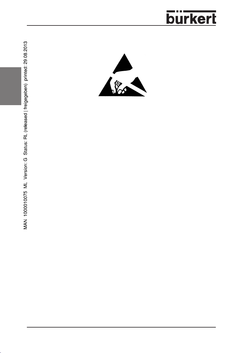
1.3 Protection from damage by electrostatic charging
english
This device contains electronic components that are sensitive to electrostatic
discharge (ESD). Contact to electrostatically charged persons or objects will
endanger these components. In the worst case, they will be immediately
destroyed or will fail after commissioning.
Observe the requirements of EN 100 015 - 1 in order to minimize the
possibility of, or avoid, damage from instantaneous electrostatic discharge.
Also take care not to touch components that are under supply voltage.
EXERCISE CAUTION ON HAND-
ATTENTION
LING !
ELECTROSTATICALLY
SENSITIVE
COMPONENTS/MODULES
4 - 8624-2 Standard

2 FUNCTIONS
The flow pressure controller type 8624-2 is primarily designed, in connection
with a proportional valve and a pressure transmitter, to keep constant the
pressure at a point in a fluidic system or to follow a given setpoint value.
The functionality of the device is characterized by:
• Compact design, capable of direct installation on the proportional valve.
• May be combined with valve types 6022, 6023, 6024, 6223, 2832, 2834.
• Controller ouput directly to proportional valve in the form of a PWM signal;
this minimizes hysteresis and optimizes the control performance.
• Any transmitter providing a 4 - 20 mA or 0 - 10 V signal can be connected
to the actual value input.
• The standard signal inputs can be scaled to the control range actually
required.
• Setting of setpoint value via standard 4 - 20 mA or 0 - 10 V signal, keypad
or bus.
• Digital control with a PI control algorithm and settable control parameters.
• Display of setpoint or actual values (to choice) on an LCD display with
selectable number of decimal places.
• Configuration with three keys.
The controller type 8624-2 can control not only pressure but also other fluidic
parameters such as flow rate, conductivity, etc. For this purpose, the sensor
that measures the actual value of the relevant parameter must provide a
standard 4 - 20 mA or 0 - 10 V signal.
For applications in which the sensor provides other types of signal for the
actual value, we offer suitable controllers, e.g:
Type 8623-2 for flow rate control with frequency input for the sensor
Type 8625-2 for temperature control with PT100 input for the sensor
english
8624-2 Standard - 5
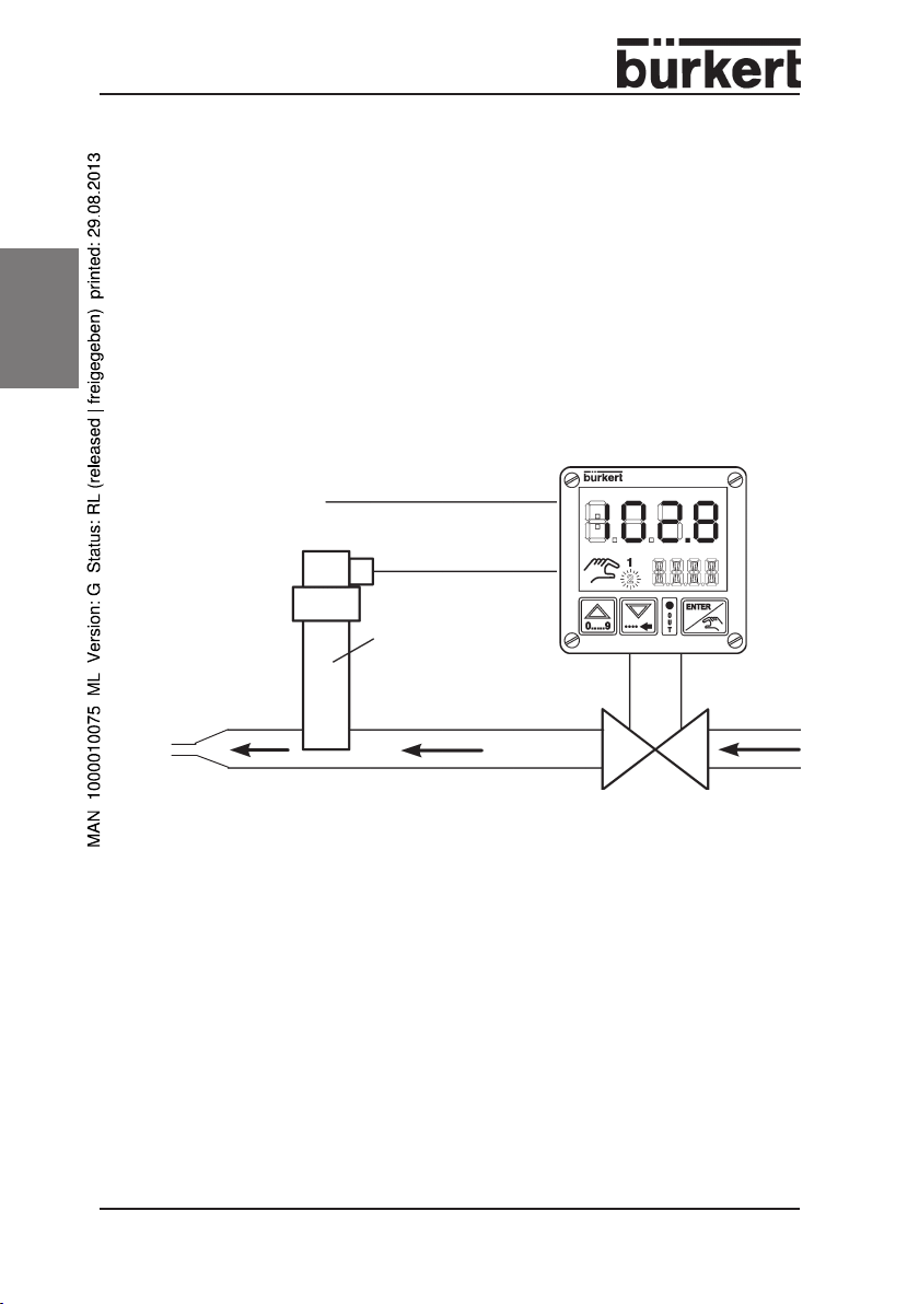
3 APPLICATION AREA
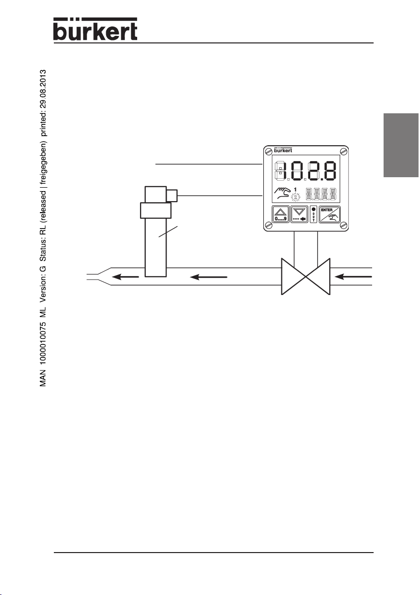
3.1 Control for constant pressure in flowing media
The compact flow pressure controller type 8624-2 can only control the
pressure of flowing media, i.e. a consumer must be present in the system. The
pressure of enclosed media cannot be controlled.
english
Example: pressure flow control for gas burners
Burner nozzle
Fig.: Structure of a flow pressure control system with the compact flow pressure
Controller type 8624-2
Setpoint input
Actual value (4 - 20 mA bzw. 0 - 10 V)
Pressure transmitter
Controlled pressure
Proportional valve
controller type 8624-2 (schematic)
6 - 8624-2 Standard
3.2 Control of other variables
The compact flow pressure controller type 8624-2 can also control other variables whose actual value is present as an analog 4 - 20 mA or 0 - 10 V signal.
Example: flow rate control with flow transmitter.
Controller type 8624-2
Setpoint input
Actual value (4 - 20 mA bzw. 0 - 10 V)
Flow transmitter
Controlled flow
Working
resistance
Proportional valve
Fig.: Structure of a flow control system with the compact flow pressure
controller type 8624-2 (schematic)
english
8624-2 Standard - 7
4 TECHNICAL DATA
Operating voltage 24 V DC
Power consumption max. 0,3 W (without proportional valve)
Output current (to valve) max. 1,0 A
Operating temperature - 10 ... + 60 °C
Interference resistance to EN50082-2
Interference emission to EN50081-2
english
Inputs
1 setpoint input 4 - 20 mA or 0 - 10 V, adjustable
1 actual value input 4 - 20 mA or 0 - 10 V, adjustable
Resolution for both inputs 10 Bit
Input impedance (4 - 20 mA) < 200 Ω
Input impedance (0 - 10 V) > 300 kΩ
Output
PWM output 24 V pulse width modulated
Controller
Control algorithm PI control
Scan time T
Amplification factor K
Reset time T
Scaling of controlled variable 0,000 - 9999
A
P
N
27 ms
0 - 10,00
0,05 - 200,1 s
Housing
Cable outlet rotatable in 90° steps
System of protection IP 65
Material polyamide
Dimensions (W x H x D) 54 x 54 x 61 mm
Order no. 143 570
8 - 8624-2 Standard
5 COMMISSIONING
NOTE
Interference with the device is only allowed by specialist
personnel using suitable tools!
Before interfering with the flow pressure controller, always
switch off the voltage!
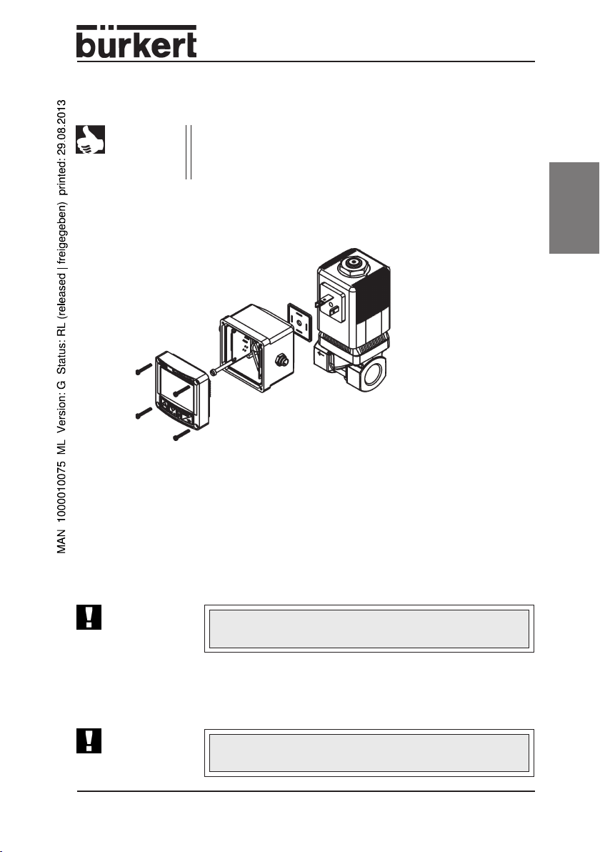
5.1 Connecting to the proportional valve
Fig.: Connecting the flow controller to the proportional valve
➔ Unscrew the 4 screws on the front panel of the flow pressure controller and
remove the cover carefully.
➔ Place the housing of the flow pressure controller with the seal onto the
valve.
english
➔ Screw the flow pressure controller tightly to the valve.
ATTENTION!
➔ Place the cover on the flow pressure controller and screw it tight with the 4
screws.
ATTENTION!
On screwing the flow pressure controller onto the proportional valve, make sure the seal is correctly seated!
Make sure the cover is placed on the right way round
(pinned strips must engage in the sockets).
8624-2 Standard - 9

5.2 Changing the cable outlet direction
➔ Unscrew the 4 screws on the front
panel of the flow pressure controller and
remove the cover carefully.
➔ Remove the screw to the valve and
remove the plastic cross.
english
➔ Detach the plate from the cube.
➔ Pull out the cube downwards and
replace in the desired orientation.
➔ Place the plate onto the cube (the pins
must engage in the guides).
➔ Lay on the plastic cross and insert the
screw through the cube.
➔ Connect the flow pressure controller to
the proportional valve (see 5.1).
Fig.: Changing the cable outlet direction
10 - 8624-2 Standard
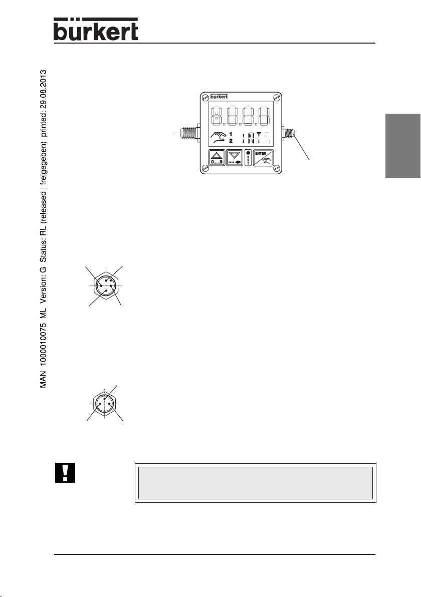
5.3 Connection configuration of flow pressure controller
type 8624-2
M12, 4-pole
Supply voltage
and
standard signal input
External setpoint
M8, 3-pole
Standard signal input
Sensor
Fig.: Connections on flow pressure controller type 8624-2
M12 (4-pole): Supply voltage and standard signal for setpoint
english
3 (blue)
M8 (3-pole) Standard signal input, sensor
1 (brown)
ATTENTION!
2 (white)
1 (brown)*4 (black)
4 (black)
3 (blue)*
Configuration
1 24 V DC supply voltage
2 Standard signal input, external setpoint
3 GND external setpoint
4 GND supply voltage
* wire colours when using standard cables with M12 plug
(4polig)
Configuration:
1 24 V DC output
3 GND
4 Standard signal input, sensor
* wire colours when using standard cables with M8 plug
(3pole)
Do not connect a voltage to pin 1 of the 3-pole plug! Pin 1 is a
24 V output to supply the sensor (e.g. 2-conductor
transmitter)
8624-2 Standard - 11
5.4 First commissioning
Settings absolutely necessary onfirst commissioning
• Type and range of standard signal (4 - 20 mA or 0 - 10 V)
• Lower limit for correcting variable (see 6.6.9
english
VALV
)
12 - 8624-2 Standard

6 OPERATING THE FLOW PRESSURE CONTROLLER
TYPE 8624-2
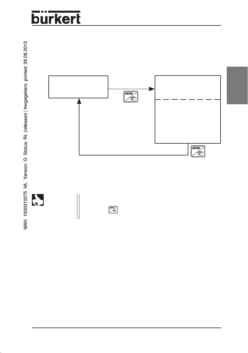
6.1 Operating modes
Three modes are possible for operating the flow pressure controller type 8624-2:
• Standard mode
• Configuration mode
• Manual mode
english
STANDARD
MODE
press key briefly
presss key for 5 sec
CONFIGURATION
MODE
Menu
.
.
.
END
press
key
Fig.: Switching between operating modes
MANUAL
MODE
8624-2 Standard - 13

NOTE
english
• After the supply voltage is switched on, the controller is in
the standard mode.
• Change to the other modes is possible by the actions
shown in the figure.
• After the configuration mode is ended, the parameters set
are transferred to the memory of the controller.
• After the operating voltage is switched off, the parameters
last active are stored; on next switching on again, these will
be active again.
6.2 Indications on the display
to indicate the process
4-digit display
values and parameters
Bus active
Manual
mode
Indication of specified setpoint value
- internal setpoint (no display)
- external setpoint (1)
- setpoint via bus (1)
Fig.: 4-digit text display, e.g. of pressure unit in bar or psi
14 - 8624-2 Standard
4-digit text display, e.g.
of pressure unit in bar or
psi

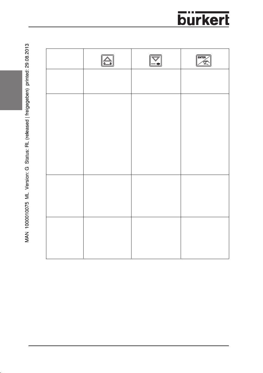
6.3 Key allocation
Mode
Standard mode
Manual mode
Configuration
mode
Menu items
Configuration
mode
Editing menu
items
key
"INC"
"DEC"
press key:
switchover of display
between set and
actual value
press key:
open valve
(inc)
press key:
backwarts in menu
press key:
increase the selected
digit*
ENTER keykey
No function on this
model.
press key:
switchover of display
between set and actual
value
press key:
close valve
(dec)
press key:
forwards in menu
press key briefly:
to next digit
press key for 2 sec.
sets decimal point
behind the place
selected
english
press key briefly:
enters manual mode
press key for 5 sec.
enters configuration
mode
press key briefly:
back to standard mode
press key:
to edit the menu item
press key:
concludes setting,
back to menu item**
* In the menu item
VALV,
setting is not digit-by-digit but in increasing
sequence within the limits 0 ... 100.
** The values set are transferred to the memory.
NOTE
The values set are only vaild for control after the configuration
mode has been left in the menu item
END
with the key.
8624-2 Standard - 15
6.4 Standard mode
In this mode, the device works after switching on the operating voltage.
The current actual value of the controlled variable is now indicated.
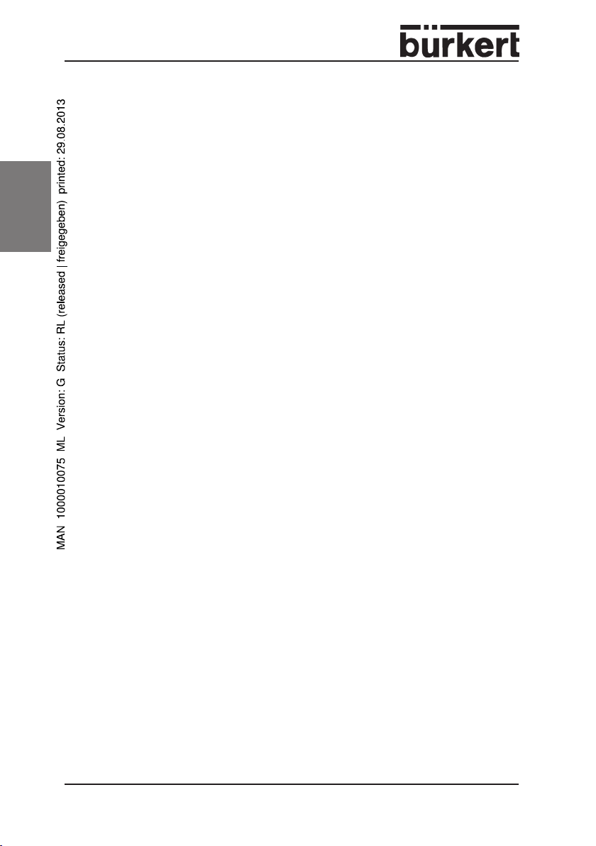
6.4.1 Standard mode and internal setpoint
In this mode, the setpoint is specified via the keys of the display.
english
Display of actual value (bar)
Display of setpoint value (bar)
Setting internal
setpoint
Fig.: Possible display in standard mode with internal set point
16 - 8624-2 Standard
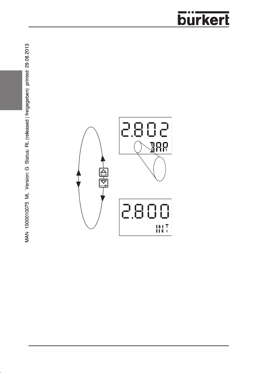
6.4.2 Standard mode and external setpoint
Here the controller receives the setpoint value via the 4 - 20 mA or 0 - 10 V signal
present on pins 2 and 3 of the 4-pole M12 plug.
Display of actual value (bar)
1
Setting external setpoint
Display of setpoint value (bar)
Fig.: Possible display in standard mode with external setpoint
english
8624-2 Standard - 17
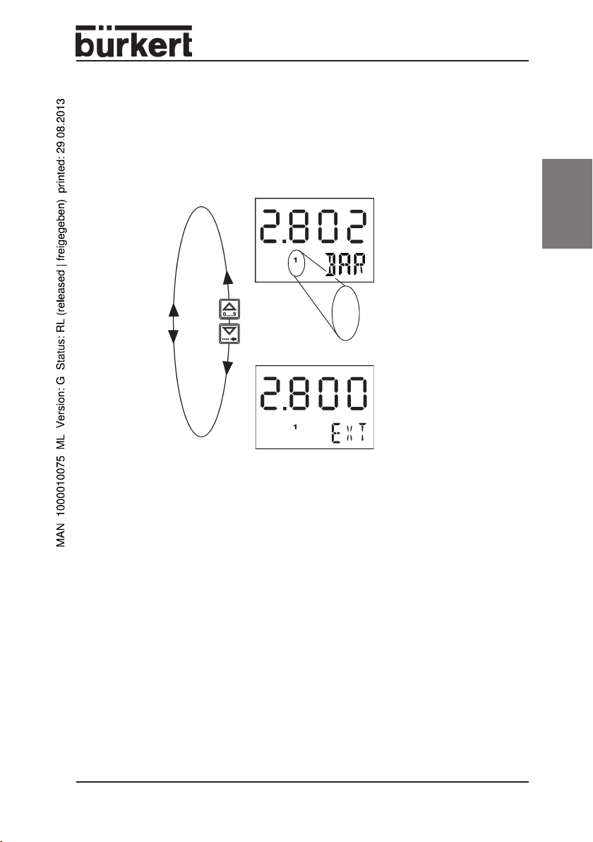
6.5 Manual mode
The manual mode can be activated from the standard mode by briefly pressing
the key.
In the manual mode there is no control: the value of correcting variable last
calculated is at first retained. By pressing the arrow keys, the correcting variable
can be increased or decreased.
Î With this key you increase the pulse-duty factor of the proportio-
nal valve, i.e. the latter opens up to a max. of 100%.
english
Î With this key you reduce the pulse-duty factor of the proportional
valve.
Î Press the key in the manual mode. On release of the key, you
will return to the standard mode.
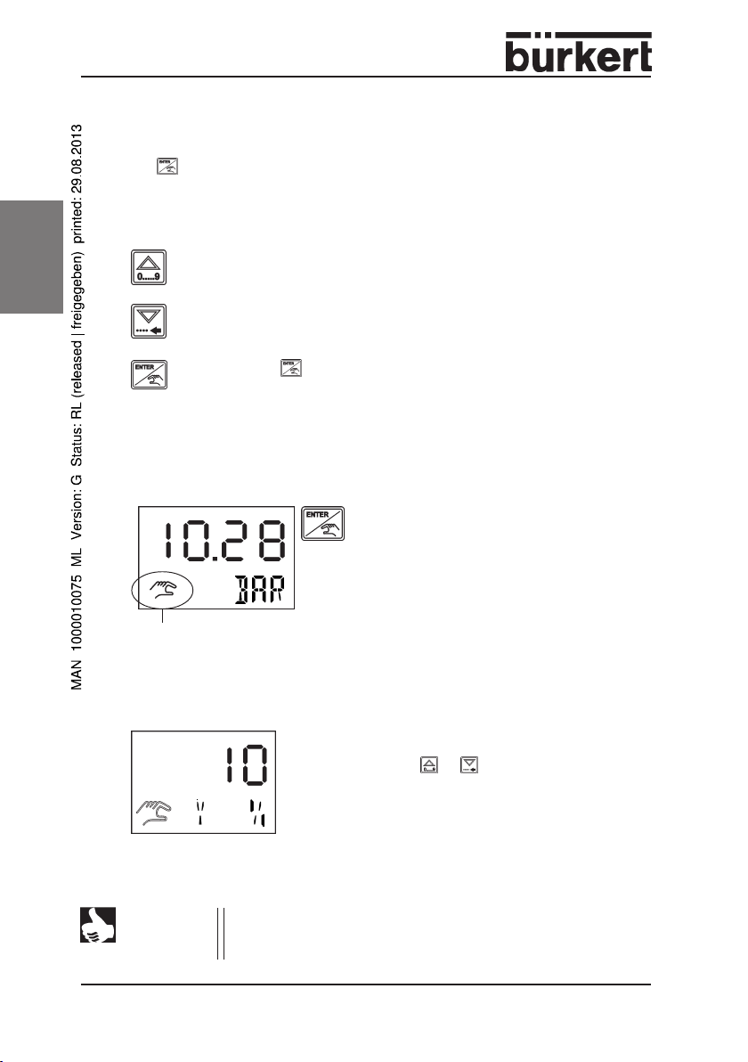
Display in manual mode
Display of actual value
Î After switching to the manual mode,
the current actual value is displayed.
Manual mode activated
Fig.: Display after switching to the manual mode
Display of the pulse-duty factor of the valve
Fig.: Display of the pulse-duty factor of the valve
NOTE
18 - 8624-2 Standard
The display
to the PWM signal set in the menu item
to a pulse-duty factor of 100 %.
0 %
As soon as the correcting variable is changed by
pressing the or key, the display switches
automatically to the value of the corecting variable. After releasing the key, the current value is
shown again.
corresponds to the minimum pulse-duty factor
VALV:
100 % corresponds
6.6 Configuration mode
In the configuration mode, the settings on the controller can be adapted to the
current application. The control process continues to run in the background with
the previously active parameters.
STANDARD
CONFIGURATION
MODE
press key for 5 sec
Fig.: Switching over from standard to configuration mode
NOTE
Values that are changed within the configuration mode only
become active when this mode is left in the menu item
pressing the key or after switching the device off and on
again.
MODE
MENU
.
.
.
END
END
press
key
by
english
8624-2 Standard - 19
Key allocation in configuration mode
english
Menu level
Edit menu
items
UNIT, SENS,
MODE, AMPL,
INTG, INV,
ZERO
Edit menu
item
VALV
Menu item
END
press key:
backwards in menu
press key:
increase the
selected digit or
select the
respective menu
subitem
press key:
increase the value,
e.g.
00 ... 100
press key:
forwards in menu
press key briefly:
to next digit
press key for 2
sec.:
set decimal point
behind the position
selected
press key:
decrease the value,
e.g.
100 ... 00
press key:
to edit the menu
item
press key:
conclude setting,
return to menu item
(menu level)*
press key:
conclude setting,
return to active
menu item (menu
level)*
press key:
conclude settings,
return to standard
mode **
* The values set are stored in the memory, but become active only after
leaving the configuration mode for the current control procedure.
** On leaving the configuration mode, the values currently set become valid
for the controller. The current control is continued with the new parameters!
20 - 8624-2 Standard
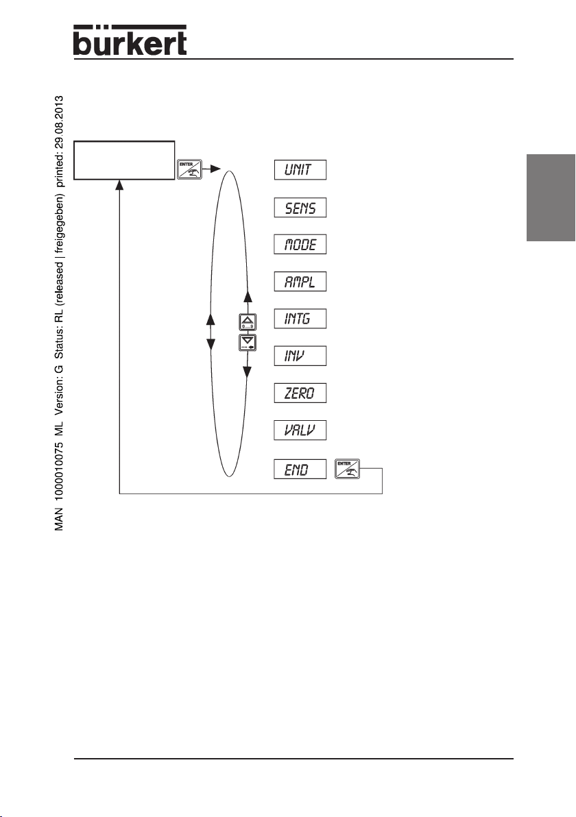
6.6.1 Menu of configuration mode
STANDARD
MODE
5 s
Settings
Unit of controlled variable
(see 6.6.2)
Sensor signal
(see 6.6.3)
Setpoint
(see 6.6.4)
english
Fig.: Menu of the configuration mode
Amplification K
(see 6.6.5)
Reset time T
(see 6.6.6)
Control inverted/non-inverted
(see 6.6.7)
Zero point switch-off
(see 6.6.8)
Adaptation of controller
correcting variable (see 6.6.9)
Storage of the values set
(see 6.6.10)
P
N
8624-2 Standard - 21
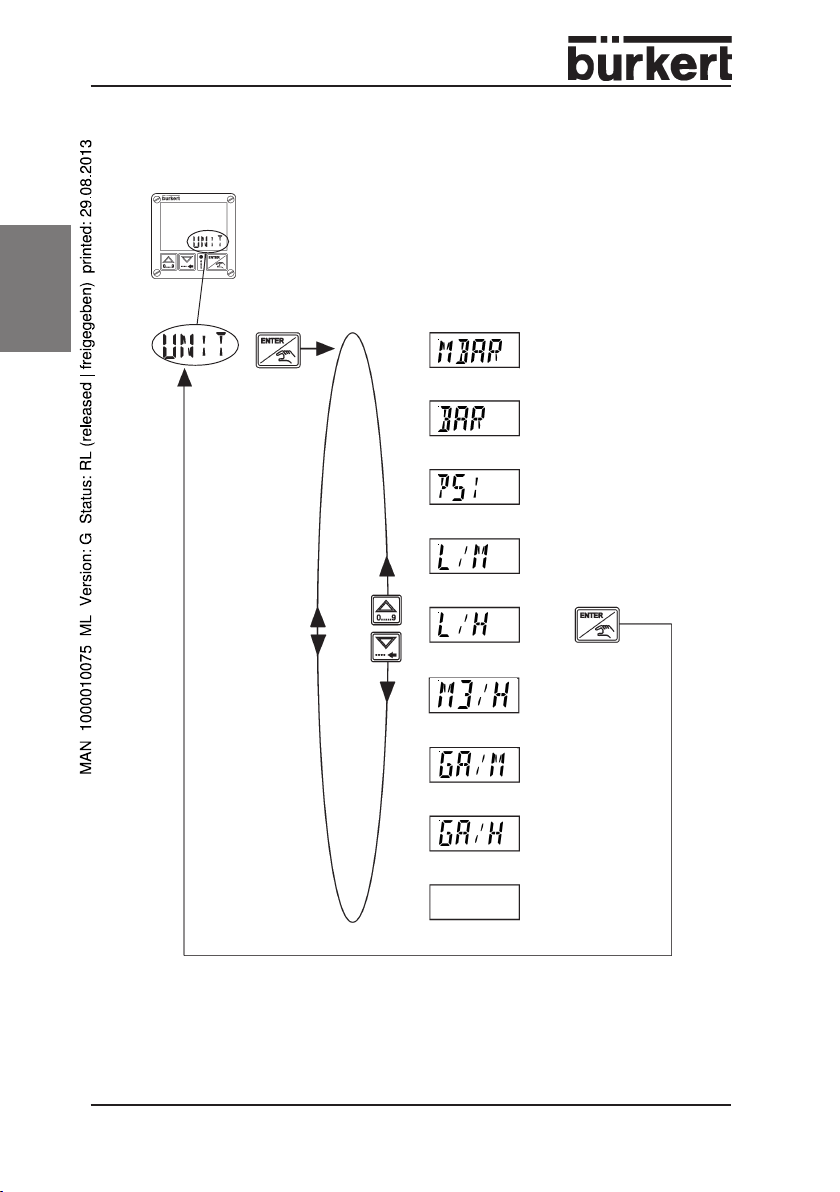
6.6.2
UNIT
- setting the unit of the controlled variable
Î Select here the unt of the controlled
variable (factory setting: bar).
english
Unit = mbar
Unit = bar
Unit = psi
Unit = litre/minute
Unit = litre/hour
Unit = m3/hour
Unit = gallons/minute
Unit = gallons/hour
no unit *
* For control systems whose controlled variable corresponds to none of the
units that can be set (e.g. with conductivity), display of the unit can be
suppressed here.
Fig.: Setting the unit of the controlled variable
22 - 8624-2 Standard
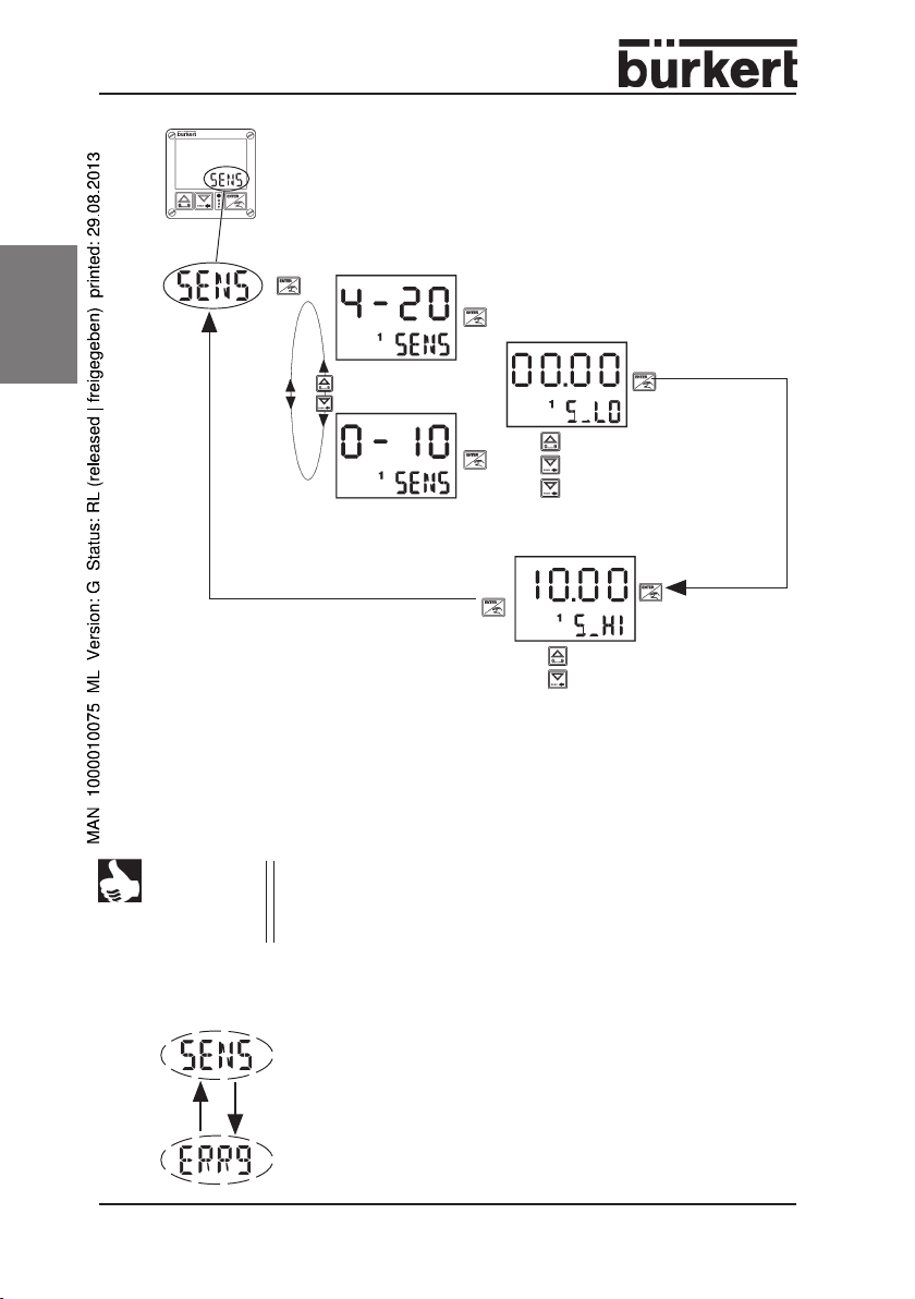
6.6.3
SENS
Î Select here whether the sensor is to send 4 - 20 mA or 0 - 10 V to the
Î Next enter the scaling. The range corresponding to the standard signal (4 -
Settings between 0.000 and 9999 are possible. The unit corresponds to the value
set in the menu item
(factory setting: S LO=0.00; S HI=10.00)
Example:
- setting the sensor input
controller for the actual value of the controlled variable (factory setting: 0 10 V).
20 mA or 0 - 10 V) is set, i.e. the pressure or flow rate or another type of
controlled variable is entered at 4 mA or 0 V (lower limit) and at 20 mA or 10
V (upper limit).
UNIT
.
english
Lower limit (
Upper limit (
=> An actual value signal of 12 mA corresponds in this case to 11.25 bar
S LO
) 2,5 bar 4 mA
S HI
) 20 bar 20 mA
8624-2 Standard - 23
english
Fig.: Setting the sensor input
2 s
increase digit
next digit
set decimal point
increase digit
next digit
The decimal point is set during the setting of
LO, S HI, SET, EXLO, EXHI
NOTE
If the sensor scaling is changed, then the setpoint scaling (
EXHI
) is automatically overwritten with values of the sensor
scaling. The internal setpoint (
Error messages in the menu
If the value for
S LO
flashing alternately on the text display.
In this chase the newly set values are not stored!
24 - 8624-2 Standard
S LO.
It then applies for the values
and cannot be changed within these menu items.
SET
) is set to
S LO.
SENS
S HI
or equal to it, the texts
was selected lower than that for
SENS
and
ERR9
appear
S
EXLO,

6.6.4
MODE
Fig.: Setting the setpoint mode
- setting the setpoint mode
Î Select here whether the device shall work with internal or
external setpoint. The choice
the number “1” in the lower display line.
(factory setting: external setpoint
External Setpoint
internal
setpoint
external
1
setpoint
is shown by
english
Setting the setpoint: internal setpoint
With internal setpoint setting, the setpoint value for the controlled variable is
entered in the previously set unit and stored. The device controls to this value.
Settings are possible within the values of the sensor scaling(see 6.6.3)
(factory setting: 00.00).
The unit corresponds to the value set in the menu item
Fig.: Setting the setpoint: internal setpoint
UNIT
increase digit
next digit
.
8624-2 Standard - 25

english
Setting the setpoint: external setpoint
For external setpoint setting you state a scaling.
The range corresponding to the standard signal (4 - 20 mA, 0 - 10 V)
must be set, i.e. the pressure or flow rate is entered at 4 mA or 0 V (lower
limit) and at 20 mA or 10 V (upper limit). Settings are possible within the
values of the sensor scaling(see 6.6.3) (factory setting: EXLO=0.00;
EXHI=10.00).
The unit corresponds to the value set in the menu item UNIT.
Example:
Lower limit (
Upper limit (
EXLO
) 2,5 bar 4 mA
EXHI)
Standard signal 4 - 20 mA
Standard signal 0 - 10 V
20 bar 20 mA
increase digit
next digit
Fig.: Setting the setpoint: external setpoint
Error messages in the menu
If the value for EXHI was selected lower than that for
EXLO
appear flashing alternately on the text display.
In this case the newly set values are not stored,
but are overwritten with the values of the sensor
scaling (S LO, S HI).
26 - 8624-2 Standard
MODE
or equal to it, the texts
MODE
and
increase digit
next digit
ERR9
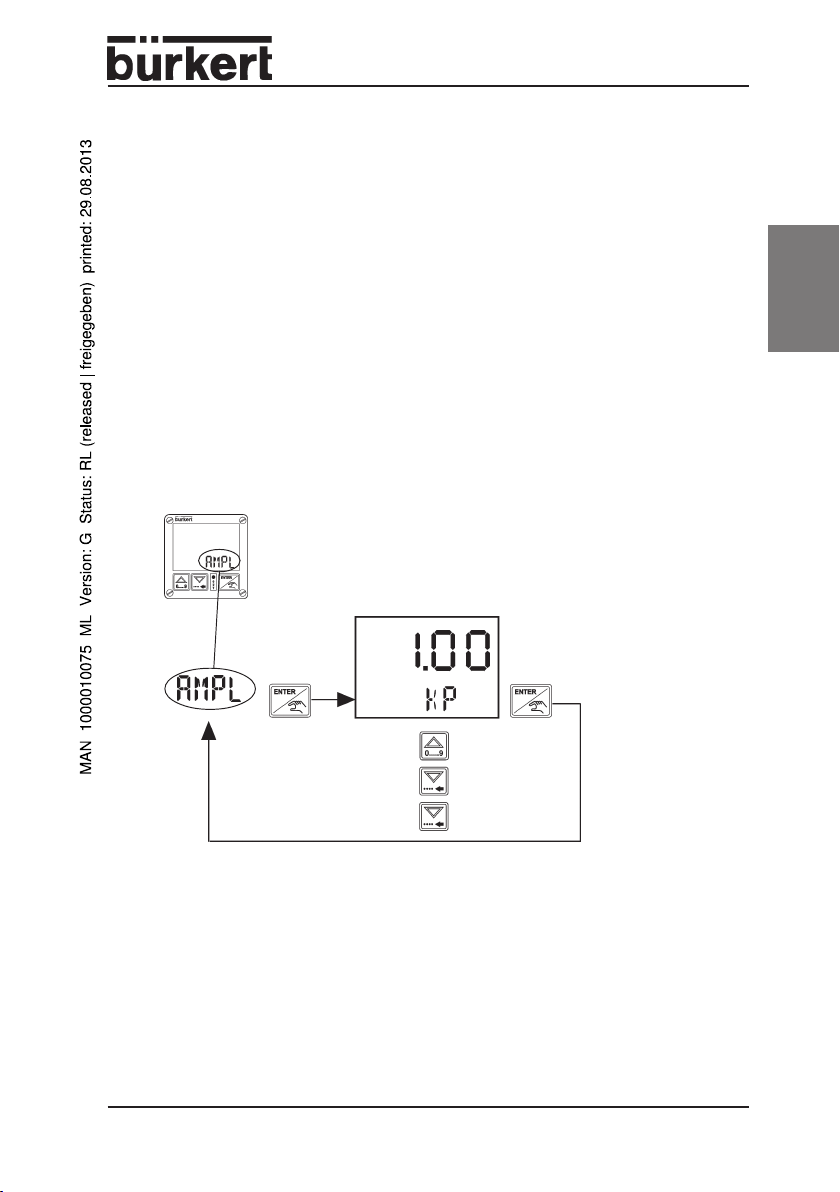
6.6.5
AMPL
Î Select the amplification factor KP in a range from 0.00 to 10.00 (factory
- setting the amplification K
setting: 1.00). If it is attempted to set a higher value, the display will jump
automatically to 0 and a value must be entered within the range. For the
internal calculations, the value set for KP is referred to range set in the
menu item SENS.
p
Setting aid:
• If excessive overshoot occurs at the value of KP set or the control
becomes unstable, you should decrease KP.
• On the other hand, unsatisfactory control dynamics may be improved by
raising KP as long as the abovementioned instability does not occur.
1
increase digit
next digit
2 s set decimal point
Fig.: Setting the amplification K
p
english
8624-2 Standard - 27

6.6.6
english
INTG
- setting the reset time T
The reset time TN is the time that is needed to obtain the same magnitude of
change in the controller output with the I fraction as occurs with the P fraction.
Î Select the reset time TN in a range from 0.05 to 200.1 sec (works setting:
0.50). Higher values result automatically in the display 0.1 and a value
within the range must be entered.
1
2 s set decimal point
N
increase digit
next digit
Fig.: Setting the reset time T
28 - 8624-2 Standard
N

Characteristics of PI controllers
A PI controller has a proportional and an integral fraction (P and I fractions).
P fraction:
Function:
y = Kp · x
d
Kp is the proportionality index (amplification factor). It is the ratio of the controller
output range DY to the proportional range Dxd.
Characteristic and step response of the P fraction of a PI controller
x
d
y
max
kp*x
y
0
y
min
Proportional range ∆x
Correcting range ∆y
x
d
d
d
Characteristic Step response
Characteristics:
A purely P controller works theoretically undamped, i.e. it is fast and hence
dynamically favourable. It has a residual control difference, i.e. it does not
completely eliminate the effects of disturbances and is thus relatively unfavourable
from a static viewpoint.
english
8624-2 Standard - 29

I fraction:
1
Function:
y =
∫ ∫
∫ xd dt
∫ ∫
T
i
Ti is the integration or floating time. It is the time that expires until the controller
output has run through the entire correcting range.
english
Characteristic and step response of the P fraction of a PI controller
x
x
d
y
max
x
d
y
control range ∆x
min
c
Floating time T
i
correcting range ∆y
Characteristic Step response
Characteristics
A purely I controller completely eliminates the effects of disturbances. It thus has a
favourable static behaviour. Because of its finite correcting speed, it works more
slowly than a P controller and tends to oscillation. It is hence dynamically relatively
unfavourable.
Superimposing the P and I fractions:
With a digital controller with sampling time TA and noting that Ti = Kp/T
write:
y = Kp (xd + TA/TN
∑∑
∑ xd)
∑∑
y : controller output
Kp : amplification factor
xd : deviation (xd = w - x)
TA : sampling time
TN : reset time
30 - 8624-2 Standard
one can
N,

Rules for adjusting PI controllers
The literature on control technology contains a number of rules by which a
favourable setting of the controller parameters can be determined experimentally.
In order to avoid incorrect settings, the conditions under which the rules were set
up in each case must be kept in mind. Apart from the characteristics of the
controlled member and the controller itself, it makes a difference whether a
change in disturbance or a command variable is to be compensated.
Adjustment rules of Ziegler and Nichols (oscillation method)
With this method, the controller parameters are set on the basis of the behaviour
of the control loop at the limit of stability. These parameters are initially set such
that the control loop begins to oscillate. Critical characteristic values occurring
allow one to deduce a favourable setting of the control parameters. A prerequisite
for using this method is naturally that the control loop is permitted to oscillate.
Procedure:
• Set the controller to P control (i.e. TN = 200 s), KP initially small.
• Set the desired set point.
• Increase KP until the controller output executes continuous, undamped
oscillation.
The proportionality index (amplification factor) set at the limit of stability is
designated K
Curve of controller output at the limit of stability
X
. The resulting oscillation period is designated T
crit
Actual value
.
crit
english
Tcrit
t
8624-2 Standard - 31

english
From K
following table.
and T
crit
, the controller parameters can then be calculated using the
crit
Parameter setting according to Ziegler and Nichols:
Controller type Parameter setting
PK
PI Kp = 0,45 K
= 0,5 K
p
crit
crit
-
TN = 0,85 T
crit
The adjustment rules of Ziegler and Nichols have been determined for P members
with first order time increase and dead time. However, they apply only for
controllers with disturbance behaviour and not for those with command behaviour.
32 - 8624-2 Standard

6.6.7
INV
- inverted/non-inverted control
Î Via this function you set the sense of action between the input signal and
the setpoint of the valve (factory setting: NO).
non-inverted control y = Kp (xd + TA/T
inverted control y = - Kp (xd + TA/TN
∑ ∑
∑ xd )
∑ ∑
N
∑ ∑
∑ xd )
∑ ∑
non-inverted control (NO):
Output signal y of the PI controller
1
increases with increasing positive
control difference xd = w-x.
inverted control (
YES
):
Output signal Y of the PI controller
1
increases with increasing negative
control difference xd = w-x.
Fig.: inverted/non-inverted control
Example of an inverted control system
In the following system the actual value at the output of the unregulated pump is to
be controlled by changing the opening of the proportional valve in a return flow
loop. If the actual value is too high (xd<0), the correcting variable must be
increased (inverted control).
Pump
english
Working
resistance
Proportional valve
Sensor
Fig.: Example of an inverted control system
8624-2 Standard - 33

6.6.8
english
ZERO
Zero point switch-off enables the proportional valve to assume a tight-closing
function in addition to the control function.To obtain tight closure when the set point
is 0, at set points below 2% of the overall range, no signal is sent to the valve, so
that the entire spring force is available for tight closure. The lower 2% of the set
point range is hence not available for control purposes.
Without zero point switch-off, a signal is sent to the valve also when the set point
is 0. This signal generates just enough magnetic force for the start of opening. This
acts in opposition to the spring force, so that the valve is not perfectly tight in most
cases.
(works setting: NO)
- zero point switch-off
No zero point switch-off(NO):
The control is continuous down to the lower limit, i.e. until the
minimum pulse-duty ratio set in the menu item
reached. The valve is closed but usually not leak-free.
VALC
is
Zero point switch-off
(
YES
):
The control is continuous until
the input signal has reached a
value of less than 2%, then
the valve will be closed.
Fig.: Zero point switch-off
Preconditions for zero point switch-off:
• Zero point switch-off (YES) has been selected;
• The set point is less than 2%;
• Non-inverted control.
34 - 8624-2 Standard

6.6.9
VALV
- adaptation of controller output signal
In this menu item, the controller output can be adapted optimally to the working
range of the actuator currently covered in the application. The proportional valve is
driven by a pulse width modulated (PWM) signal from the controller. Opening of the
valve does not begin at a pulse-duty factor of 0 of the PWM signal, but on account
of the spring force opposing the magnetic force, only at a certain value. This start
of opening depends upon the nominal diameter of the valve, the admission
pressure, and because of temperature dependence of the coil resistance, also on
the coil temperature.
The function of the controller can be optimized by having its output range begin not
at 0, but at the start of opening in the current application.
Display of actual value
Î In the menu item
actual value is displayed
VALV,
english
the
Display of pulse-duty factor of valve
As soon as the controller output is changed by pressing
the or key, the display changes automatically to
controller output. On releasing the key, the actual value
is again displayed.
➔ With this key, the pulse-duty factor of the proportional valve is
increased, i.e. it opens up to a max. of 100%.
➔ With this key, the pulse-duty factor of the proportional valve is
decreased.
Fig.: Adaptation of controller output signal
8624-2 Standard - 35

english
To determine the start of opening of the proportional valve in the current
application, the following steps are executed (on first operation of the device. This
is done immediately after switching on, while the coil is still cold):
➔ On using a direct acting proportional valve (Types 6022, 6023, 6024, 6223,
2832, 2834), set the greatest operating pressure expected in the
application (the start of opening is lowered with increasing admission
pressure). With a pilot controlled proportional valve (Type 6223), on the
other hand, set the lowest admission pressure to be expected in operation
(in this case, the start of opening is raised with increasing admission
pressure).
➔ Select the menu item VALV in the configuration mode. The actual value is
displayed.
➔ If at the controller output obtaining no recognizable flow is present, first
increase the pulse-duty factor by pressing the key until flow is detected.
➔ Now lower the pulse-duty factor by pressing the key until the valve is
just closed, i.e. no flow is present.
➔ Press the key: the value for start of opening will be stored.
36 - 8624-2 Standard

6.6.10
END
Standard
mode
Fig.: Storing the values
- storing the values
english
NOTE
The parameters set in the menu items of the configuration mode
will already be transferred to memory after leaving the respective
menu item and hence be valid after the next time the device is
switched off and on. Only after leaving the configuration mode in
the menu item END with the key will the parameters also be
valid for the current control process.
8624-2 Standard - 37

6.7 Settings on delivery
Menu Parameter Value set
english
UNIT
SENS
S LO
S HI
MODE
EXLO
EXHI
SET
AMPL
INTG
INV
ZERO
VALV
Unit bar
Type of sensor signal 0 - 10 V
lower limit 0,00 bar
upper limit 10,00 bar
type of setpoint setting ext. setpoint 0 - 10V
lower limit 0,00 bar
upper limit 10,00 bar
setpoint 0,00 bar
K
p
T
N
inverted/non-inverted control non-inverted
zero point switch-off deactivated
lower limit of controller output to valve 0 %
1,00
0,50 s
38 - 8624-2 Standard

7 ERROR MESSAGES
Display Cause Remedy
ERR0
ERR1
ERR2
ERR9
Standard signal at transmitter Check standard signal of transinput lies outside range mitter or its connection to controller
(4 - 20 mA, 0 - 10 V)
Standard signal of external Check standard signal
setpoint lies outside range
(4 - 20 mA, 0 - 10 V)
Controller output to proportional Increase the pressure in order to
valve is > 95% reach the required setpoint with
Only in mode
S LO
EXLO
Actual value too great (can no
longer be compensated) or in
manual mode, the valve
cannot be closed
SENS
≥
≥
S HI
EXHI
with Set the lower limit for the valve drive
or correctly value (see 6.6.9.
the proportional valve selected
VALV
Set the lower limit for valve drive
correctly (see 6.6.9
VALV
)
)
english
8624-2 Standard - 39

english
40 - 8624-2 Standard

INHALT
1 ALLGEMEINE HINWEISE........................................................................................ 43
1.1 Darstellungsmittel .......................................................................................................................... 43
1.2 Sicherheitshinweise ..................................................................................................................... 43
1.3 Schutz gegen Beschädigung durch elektrostatische
Aufladung ............................................................................................................................................... 44
2 FUNKTION .................................................................................................................................... 45
3 EINSATZBEREICH
3.1 Druckregelung für konstanten Druck in strömenden Medien .............. 46
3.2 Regelung anderer Größen ...................................................................................................... 47
............................................................................................................ 46
4 TECHNISCHE DATEN .................................................................................................. 48
5 INBETRIEBNAHME
5.1 Anschluss an das Proportionalventil .......................................................................... 49
5.2 Richtungsänderung des Kabelabgangs .................................................................... 50
5.3 Anschlussbelegung des Fließdruckreglers Typ 8624-2 ............................. 51
5.4 Erstinbetriebnahme ...................................................................................................................... 52
.......................................................................................................... 49
6 BETRIEB DES FLIESSDRUCKREGLERS
TYP 8624-2 ....................................................................................................................................53
6.1 Betriebsmodi ...................................................................................................................................... 53
6.2 Anzeigen im Display ................................................................................................................... 54
6.3 Tastenbelegung ................................................................................................................................ 55
6.4 Standardmodus ................................................................................................................................56
6.4.1 Standardmodus und interner Sollwert ........................................................... 56
6.4.2 Standardmodus und externer Sollwert .......................................................... 57
deutsch
6.5 Handmodus.......................................................................................................................................... 58
8624-2 Standard - 41

6.6 Konfigurationsmodus .................................................................................................................. 59
6.6.1 Menü des Konfigurationsmodus ......................................................................... 61
6.6.2
UNIT
- Einstellung der Einheit der Regelgröße ...................................... 62
SENS
6.6.3
6.6.4
6.6.5
6.6.6
6.6.7
6.6.8
6.6.9
6.6.10
- Einstellung des Sensoreingangs.................................................... 63
MODE
- Einstellung der Sollwertvorgabe .................................................. 65
AMPL
- Einstellung der Verstärkung K
INTG
- Einstellung der Nachstellzeit T
INV
- Invertierte / nichtinvertierte Regelung ............................................... 73
ZERO
- Nullpunktabschaltung .............................................................................. 74
VALV
- Anpassung Regler - Stellgröße ....................................................... 75
END
- Speichern der Werte .................................................................................... 77
......................................................... 67
P
......................................................... 68
N
6.7 Einstellungen bei Auslieferung ......................................................................................... 78
deutsch
7 FEHLERMELDUNGEN................................................................................................. 79
42 - 8624-2 Standard

1 ALLGEMEINE HINWEISE
1.1 Darstellungsmittel
In dieser Betriebsanleitung werden folgende Darstellungsmittel verwendet:
markiert einen Arbeitsschritt, den Sie ausführen müssen
ACHTUNG!
HINWEIS
kennzeichnet Hinweise, bei deren Nichtbeachtung Ihre Gesundheit oder die Funktionsfähigkeit des Gerätes gefährdet
ist.
kennzeichnet wichtige Zusatzinformationen, Tipps und
Empfehlungen
1.2 Sicherheitshinweise
Bitte beachten Sie die Hinweise dieser Betriebsanleitung sowie die Einsatzbedingungen und zulässigen Daten, die in den Datenblättern des verwendeten
Proportionalventils sowie des Reglers Typ 8624-2 spezifiziert sind, damit das
Gerät einwandfrei funktioniert und lange einsatzfähig bleibt:
• Halten Sie sich bei der Einsatzplanung und dem Betrieb des Gerätes an die
allgemeinen Regeln der Technik!
• Eingriffe dürfen nur durch Fachpersonal und mit geeignetem Werkzeug
erfolgen!
• Beachten Sie die geltenden Unfallverhütungs- und Sicherheitsbestimmun-
gen für elektrische Geräte während des Betriebs, der Wartung und der
Reparatur des Gerätes!
• Schalten Sie vor Eingriffen in das System in jedem Fall die Spannung ab!
deutsch
• Treffen Sie geeignete Maßnahmen, um unbeabsichtigtes Betätigen oder
unzulässige Beeinträchtigung auszuschließen!
• Bei Nichtbeachtung dieser Hinweise und unzulässigen Eingriffen in das
Gerät entfällt jegliche Haftung unsererseits, ebenso erlischt die Garantie
auf Geräte und Zubehörteile!
8624-2 Standard - 43

1.3 Schutz gegen Beschädigung durch elektrostatische
Aufladung
deutsch
Das Gerät enthält elektronische Bauelemente, die gegen elektrostatische
Entladung (ESD) empfindlich reagieren. Berührung mit elektrostatisch aufgeladenen Personen oder Gegenständen gefährdet diese Bauelemente. Im
schlimmsten Fall werden sie sofort zerstört oder fallen nach der Inbetriebnahme aus.
Beachten Sie die Anforderungen nach EN 100 015 - 1, um die Möglichkeit
eines Schadens durch schlagartige elektrostatische Entladung zu minimieren bzw.
zu vermeiden. Achten Sie ebenso darauf, dass Sie elektronische Bauelemente
nicht bei anliegender Versorgungsspannung berühren.
VORSICHT BEI HANDHABUNG !
ACHTUNG
ELEKTROSTATISCH
GEFÄHRDETE
BAUELEMENTE / BAUGRUPPEN
44 - 8624-2 Standard

2 FUNKTIONEN
Der Fließdruckregler Typ 8624-2 ist primär darauf abgestimmt, in Verbindung
mit einem Proportionalventil und einem Drucktransmitter den Druck an einer
Stelle eines fluidischen Systems konstant zu halten oder einem vorgegebenen
Sollwert nachzuführen.
Die Funktionalität des Gerätes wird gekennzeichnet durch:
• Kompakte Bauform, direkt auf ein Proportionalventil aufsteckbar.
• Kombinierbarkeit mit den Proportionalventiltypen 6022, 6023, 6024, 6223,
2832, 2834.
• Ausgabe der Stellgröße in Form eines PWM-Signals direkt an das Proportionalventil; dadurch wird die Hysterese minimiert und die Regelgüte optimiert.
• An den Istwerteingang sind beliebige Transmitter anschließbar, die ein Signal
von 4 - 20 mA oder 0 - 10 V bereitstellen.
• Die Normsignaleingänge können auf den tatsächlich geforderten Regelbereich
skaliert werden.
• Sollwertvorgabe über Normsignal 4 - 20 mA bzw. 0 - 10 V, über Tastatur
oder über Bus.
• Digitale Regelung mit einem PI-Regelalgorithmus und einstellbaren Regelparametern.
• Anzeige von Soll- oder Istwert (wahlweise) auf einem LCD-Display mit
wählbarer Anzahl von Dezimalstellen.
• Konfiguration mit drei Tasten.
Der Regler Typ 8624-2 kann über die Druckregelung hinaus auch zur Regelung anderer fluidischer Größen wie z.B. Durchfluss, Leitfähigkeit u.a. verwendet
werden. Zu diesem Zweck muss der Sensor, der den Istwert der betreffenden
Größe erfasst, eines der Normsignale 4 - 20 mA oder 0 - 10 V bereitstellen.
Für Applikationen, in denen der Sensor für den Istwert andere Signalarten
ausgibt, bieten wir geeignete Regelgeräte an, z.B.:
Typ 8623-2 für Durchflussregelung mit Frequenzeingang für den Sensor
Typ 8625-2 für Temperaturregelung mit PT100-Eingang für den Sensor
deutsch
8624-2 Standard - 45

3 EINSATZBEREICH
3.1 Druckregelung für konstanten Druck in strömenden
Medien
Der kompakte Fließdruckregler Typ 8624-2 ist nur in der Lage, den Druck fließender Medien zu regeln, d.h. es muss ein Verbraucher im System enthalten sein.
Eingeschlossene Medien können nicht geregelt werden.
Beispiel: Fliessdruckregelung für Gasbrenner
Regler Typ 8624-2
deutsch
Brennerdüse
Bild: Aufbau einer Fliessdruckregelung mit dem kompakten Fließdruckregler
Sollwerteingang
Istwert (4 - 20 mA bzw. 0 - 10 V)
Drucktransmitter
geregelter Druck
Proportionalventil
Typ 8624-2 (Schema)
46 - 8624-2 Standard

3.2 Regelung anderer Größen
Mit dem Fließdruckregler Typ 8624-2 können auch andere Größen, deren
Istwert als analoges 0 - 10 V oder 4 - 20 mA-Signal vorliegt, geregelt werden.
Beispiel: Durchflussregelung mit Durchflusstransmitter.
Regler Typ 8624-2
Sollwerteingang
Istwert (4 - 20 mA bzw. 0 - 10 V)
Durchflusstransmitter
geregelter
Durchfluss
Arbeitswiderstand
Bild: Aufbau einer Durchflussregelung mit dem kompakten Fließdruckregler
Typ 8624-2 (Schema)
Proportionalventil
deutsch
8624-2 Standard - 47

4 TECHNISCHE DATEN
Betriebsspannung 24 V DC
Leistungsaufnahme max. 0,3 W (ohne Proportionalventil)
Ausgangsstrom (zum Ventil) max. 1,0 A
Betriebstemperatur - 10 ... + 60 °C
Störfestigkeit nach EN50082-2
Störaustrahlung nach EN50081-2
Eingänge
1 Sollwerteingang 4 - 20 mA bzw. 0 - 10 V, einstellbar
1 Istwerteingang 4 - 20 mA bzw. 0 - 10 V, einstellbar
Auflösung für beide Eingänge 10 Bit
Eingangsimpedanz (4 - 20 mA) < 200 Ω
Eingangsimpedanz (0 - 10 V) > 300 kΩ
deutsch
Ausgang
PWM-Ausgang 24 V - pulsweitenmoduliert
Regler
Regelalgorithmus PI-Regler
Abtastzeit T
Verstärkungsfaktor K
Nachstellzeit T
Skalierung der Regelgröße 0,000 - 9999
A
N
27 ms
P
0 - 10,00
0,05 - 200,1 s
Gehäuse
Kabelabgang in 90° - Schritten drehbar
Schutzart IP 65
Werkstoff Polyamid
Abmessungen (B x H x T) 54 x 54 x 61 mm
Bestell-Nr. 143 570
48 - 8624-2 Standard

5 INBETRIEBNAHME
HINWEIS
Eingriffe dürfen nur durch Fachpersonal und mit geeignetem
Werkzeug erfolgen!
Schalten Sie den Fließdruckregler vor Eingriffen spannungsfrei!
5.1 Anschluss an das Proportionalventil
Bild: Anschluss des Fließdruckreglers an das Proportionalventil
➔ Lösen Sie die 4 Schrauben an der Frontseite des Fließdruckreglers und
nehmen Sie den Deckel vorsichtig ab.
➔ Setzen Sie das Gehäuse des Fließdruckreglers mit der Dichtung auf das
Ventil auf.
deutsch
➔ Schrauben Sie den Fließdruckregler am Ventil fest.
ACHTUNG!
➔ Stecken Sie den Deckel auf den Fließdruckregler auf und schrauben Sie
ihn mit den 4 Schrauben fest.
ACHTUNG!
Achten Sie beim Verschrauben des Fließdruckreglers mit
dem Proportionalventil auf einwandfreien Sitz der Dichtung!
Achten Sie darauf, dass der Deckel richtigherum aufgesetzt
wird (Stiftleisten müssen in die Buchsen eingreifen).
8624-2 Standard - 49

5.2 Richtungsänderung des Kabelabgangs
➔ Lösen Sie die 4 Schrauben an der
Frontseite des Fliessdruckreglers und
nehmen Sie den Deckel vorsichtig ab.
➔ Entfernen Sie die Schraube zum Ventil
und nehmen sie das Kunststoffkreuz
ab.
➔ Nehmen Sie die Platine vom Würfel ab.
➔ Ziehen Sie den Würfel nach unten
heraus und setzen ihn in der gewünschten Richtung wieder ein.
deutsch
Bild: Richtungsänderung des Kabelabgangs
➔ Setzen Sie die Platine auf den Würfel auf
(Die Stecker müssen in die Führungen
eingreifen).
➔ Setzen sie das Kunststoffkreuz auf und
stecken Sie die Schraube durch den
Würfel.
➔ Schliessen Sie den Fließdruckregler an
das Proportionalventil an (siehe 5.1).
50 - 8624-2 Standard

5.3 Anschlussbelegung des Fließdruckreglers Typ 8624-2
Versorgungsspannung
M12, 4-polig
und
Normsignaleingang
Externer Sollwert
M8, 3-polig
Normsignaleingang
Sensor
Bild: Anschlüsse des Fließdruckreglers Typ 8624-2
M12 (4-polig): Versorgungsspannung und Normsignaleingang für Sollwert
3 (bl)
M8 (3-polig) Normsignaleingang Sensor:
2 (ws)
1 (br)*4 (sw)
4 (sw)
Belegung
1 2 4 V DC Versorgungsspannung
2 Normsignaleingang externer Sollwert
3 GND externer Sollwert
4 GND Versorgungsspannung
* Aderfarben bei Verwendung von Standard-Kabeln mit Stecker M12
(4polig)
Belegung
1 24 V D C Ausgang
3 GND
4 Normsignaleingang Sensor
deutsch
1 (br)
ACHTUNG!
3 (bl)*
* Aderfarben bei Verwendung von Standard-Kabeln mit Stecker M8
(3polig)
Schließen Sie an Pin 1 des 3-poligen Steckers keine Spannung
an! Pin 1 ist ein 24 V - Ausgang zur Versorgung des Sensors
(z. B. 2-Leiter-Transmitter)
8624-2 Standard - 51

5.4 Erstinbetriebnahme
Zwingend notwendige Einstellungen bei Erstinbetriebnahme
• Art und Bereich der Normsignale (4 - 20 mA oder 0 - 10 V)
• unterer Grenzwert für die Stellgröße (s. 6.6.9
deutsch
VALV
)
52 - 8624-2 Standard

6 BETRIEB DES FLIESSDRUCKREGLERS TYP 8624-2
6.1 Betriebsmodi
Beim Betrieb des Fließdruckreglers Typ 8624-2 sind drei Modi möglich:
• Standardmodus
• Konfigurationsmodus
• Handmodus
STANDARD-
MODUS
Taste kurz drücken
Taste 5 s
drücken
KONFIGURATIONS-
MODUS
Menü
.
.
.
END
Taste
drücken
Bild: Umschalten zwischen den Betriebsmodi
HAND-
MODUS
deutsch
8624-2 Standard - 53

HINWEISE
6.2 Anzeigen im Display
deutsch
4stellige Anzeige
zur Anzeige der
Prozessgrößen und
Parameter
Bus aktiv
• Nach Einschalten der Versorgungsspannung befindet sich der
• Der Wechsel in die anderen Modi ist mit den im Bild gezeigten
• Nach Beenden des Konfigurationsmodus werden die ein-
• Nach Ausschalten der Betriebsspannung bleiben die zuletzt
Regler im Standardmodus.
Aktionen möglich.
gestellten Parameter in den Speicher des Reglers übertragen.
aktiven Parameter gespeichert; diese sind beim nächsten
Einschalten wieder aktiv.
Handmodus
Darstellung der Sollwertvorgabe
- interner Sollwert (keine Anzeige )
- externer Sollwert (1)
- Sollwert über Bus (1)
Bild: Display des kompakten Fließdruckreglers Typ 8624-2
54 - 8624-2 Standard
4stellige Textanzeige
z. B. Anzeige der Druckeinheit in bar oder psi

6.3 Tastenbelegung
Modus
Standardmodus
Hand-Modus
Konfigurationsmodus
Menüpunkte
Konfigurationsmodus
Menüpunkte
bearbeiten
Taste
"INC"
"DEC"
Taste drücken:
Anzeige Umschalten
zwischen Soll- und
Istwert
Taste drücken:
Ventil öffnen
(inc)
Taste drücken:
im Menü zurück
Taste drücken:
Erhöhen der ausgewählten Stelle*
ENTER-TasteTaste
in dieser Gerätevariante
ohne Funktion
Taste drücken:
Anzeige Umschalten
zwischen Soll- und
Istwert
Taste drücken:
Ventil schließen
(dec)
Taste drücken:
im Menü vor
Taste kurz drücken:
zur nächste Stelle
Taste 2 Sekunden
drücken:
Dezimalpunkt hinter die
ausgewählte Stelle
setzen
Taste kurz drücken:
in den
Hand-Modus
Taste 5 Sekunden
drücken:
in den Konfigurationsmodus
Taste kurz drücken:
zurück in den
Standardmodus
Taste drücken:
zur Bearbeitung des
Menüpunktes
Taste drücken:
Einstellung
abschließen, zurück
zum Menüpunkt**
deutsch
* Im Menüpunkt
VALV
wird nicht über Stellen eingestellt, sondern hochgezählt
in den Grenzen 0 ... 100.
** Die eingestellten Werte werden in den Speicher übernommen.
HINWEIS Für den aktuellen Regelvorgang haben die eingestellten Werte erst
dann Gültigkeit, wenn der Konfigurationsmodus im Menüpunkt
END
mit der -Taste verlassen wird.
8624-2 Standard - 55

6.4 Standardmodus
In diesem Modus arbeitet das Gerät nach Einschalten der Betriebsspannung.
Dabei wird der aktuelle Istwert der Regelgröße angezeigt.
6.4.1 Standardmodus und interner Sollwert
In diesem Modus erfolgt die Vorgabe des Sollwerts über die Tasten des Displays.
Anzeige des Istwertes (bar)
deutsch
Anzeige des Sollwertes (bar)
Einstellung
Interner Sollwert
Bild: Mögliche Anzeige im Standardmodus bei internem Sollwert
56 - 8624-2 Standard

6.4.2 Standardmodus und externer Sollwert
Hier erhält der Regler den Sollwert über das 0 - 10 V- oder 4 - 20 mA - Signal, das an
den Pins 2 und 3 des 4-poligen M12-Steckers anliegt.
Anzeige des Istwertes (bar)
1
Einstellung
Externer Sollwert
Anzeige des Sollwertes (bar)
Bild: Mögliche Anzeige im Standardmodus bei externem Sollwert
deutsch
8624-2 Standard - 57

6.5 Handmodus
Der Handmodus kann vom Standardmodus aus durch kurzes Drücken der
-Taste aktiviert werden.
Im Handmodus erfolgt keine Regelung, sondern es wird zunächst die zuletzt
berechnete Stellgröße beibehalten. Durch Drücken der Pfeiltasten kann die
Stellgröße nach oben oder unten verändert werden.
Î Sie vergrößern mit dieser Taste das Tastverhältnis des Proportional-
ventils, d.h. das Proportionalventil öffnet bis max. 100 %.
Î Mit dieser Taste verringern Sie das Tastverhältnis des
Proportionalventils.
Î Drücken Sie im Handmodus die -Taste. Beim Loslassen gelangen
Sie zurück in den Standardmodus.
deutsch
Anzeige im Handmodus
Anzeige Istwert
Î Nach dem Umschalten in den Hand-
Modus wird der aktuelle Istwert
angezeigt.
Hand-Modus aktiviert
Bild: Anzeige nach Umschalten in den Handmodus
Anzeige des Tastverhältnisses des Ventils
Bild: Anzeige des Tastverhältnisses des Ventils
HINWEIS
58 - 8624-2 Standard
Die Anzeige
minimalen Tastverhältnis des PWM-Signals, 100 % entspricht
einem Tastverhältnis von 100 %.
0 %
Sobald durch Drücken der - oder -Taste die
Stellgröße verändert wird, schaltet die Anzeige
automatisch auf den Wert der Stellgröße um, nach
Loslassen der Taste wird wieder der Istwert angezeigt.
entspricht dem im Menüpunkt
VALV
eingestellten

6.6 Konfigurationsmodus
Im Konfigurationsmodus können die Einstellungen des Reglers an die vorliegende
Anwendung angepasst werden. Die Regelung läuft im Hintergrund mit den vorher
aktiven Parametern weiter.
STANDARD-
MODUS
Taste 5 s drücken
Bild: Umschalten vom Standardmodus in den Konfigurationsmodus
HINWEIS
Werte, die innerhalb des Konfigurationsmodus verändert werden,
werden erst dann aktiv, wenn dieser im Menüpunkt
-Taste verlassen wird, oder nach Aus- und Wiedereinschalten
des Gerätes.
KONFIGURATIONS-
MODUS
MENÜ
.
.
.
END
END
mit der
Taste
drücken
deutsch
8624-2 Standard - 59

Tastenbelegung im Konfigurationsmodus
deutsch
Menüebene
Menüpunkte
bearbeiten
UNIT, SENS,
MODE, AMPL,
INTG, INV,
ZERO
Menüpunkt
bearbeiten
VALV
Menüpunkt
END
Taste drücken:
im Menü zurück
Taste drücken:
Erhöhen der ausgewählten Stelle oder
Auswahl des jeweiligen Menüunterpunktes
Taste drücken:
Erhöhen des Wertes,
von 00 bis 100
Taste drücken:
im Menü vor
Taste kurz drücken:
zur nächste Stelle
Taste 2 Sekunden
drücken:
Dezimalpunkt hinter
die ausgewählte
Stelle setzen
Taste drücken:
Erniedrigen des
Wertes,
von 100 bis 00
Taste drücken:
zur Bearbeitung des
Menüpunktes
Taste drücken:
Einstellung
abschließen, zurück
zum aktiven Menüpunkt (Menüebene) *
Taste drücken:
Einstellung
abschließen, zurück
zum aktiven Menüpunkt (Menüebene) *
Taste drücken:
Einstellungen abschließen,
zurück zum
Standardmodus **
* Die eingestellten Werte werden in den Speicher übernommen, aber erst nach
Verlassen des Konfigurationsmodus für den aktuellen Regelvorgang aktiv.
** Beim Verlassen des Konfigurationsmodus erhalten die aktuell eingestellten
Werte für den Regler Gültigkeit. Die laufende Regelung wird mit den neuen
Parametern fortgesetzt!
60 - 8624-2 Standard

6.6.1 Menü des Konfigurationsmodus
STANDARD-
MODUS
5 s
Einstellungen
Einheit der Regelgröße
(s. 6.6.2)
Sensoreingang
(s. 6.6.3)
Sollwertvorgabe
(s. 6.6.4)
Bild: Menü des Konfigurationsmodus
Verstärkung K
(s. 6.6.5)
Nachstellzeit T
(s. 6.6.6)
inventierte / nicht invertierte
Regelung (s. 6.6.7)
Nullpunktabschaltung
(s. 6.6.8)
Anpassung Regler-Stellgröße
(s. 6.6.9)
P
N
Übernahme der eingestellten Werte (s. 6.6.10)
deutsch
8624-2 Standard - 61

6.6.2
UNIT
- Einstellung der Einheit der Regelgröße
Î Wählen Sie hier die Einheit der Regelgröße
aus (Werkseinstellung: bar)
Einheit = mbar
Einheit = bar
deutsch
* Für Regelungen deren Regelgröße keiner der einstellbaren Einheiten entspricht
Einheit = psi
Einheit = Liter/Minute
Einheit = Liter/Stunde
Einheit = m3/Stunde
Einheit = Gallonen/Minute
Einheit = Gallonen/Stunde
keine Einheit *
(z.B. bei Leitfähigkeit) kann die Anzeige der Einheit hiermit ausgeblendet
werden.
Bild: Einstellung der Einheit der Regelgröße
62 - 8624-2 Standard

6.6.3
SENS
Î Stellen Sie hier ein, ob der Sensor für den Istwert der Regelgröße 4 - 20 mA
Î Geben Sie anschließend eine Skalierung an. Dabei wird der dem Normsignal (4
Einstellungen sind zwischen 0,000 und 9999 möglich. Die Einheit entspricht dem
im Menüpunkt
(Werkseinstellung:
Beispiel:
- Einstellung des Sensoreingangs
oder 0 - 10 V an den Regler ausgibt (Werkseinstellung: 0-10 V).
- 20 mA, 0 - 10 V) entsprechende Bereich eingestellt. D. h. es erfolgt die
Eingabe des Druckes oder Durchflusses oder einer andersartigen Regelgröße
bei 4 mA bzw. 0 V (unterer Grenzwert) und bei 20 mA bzw. 10 V (oberer
Grenzwert).
UNIT
eingestellten Wert.
S LO
= 0,00 ;
S HI
= 10,00)
deutsch
Unterer Grenzwert (
Oberer Grenzwert (
=> ein Istwertsignal von 12 mA entspricht in diesem Fall dann 11,25 bar
S LO
) 2,5 bar 4 mA
S HI
) 20 bar 20 mA
8624-2 Standard - 63

deutsch
Bild: Einstellung des Sensoreingangs
2 s
Erhöhen der Stelle
nächste Stelle
Dezimalpunkt setzen
Erhöhen der Stelle
nächste Stelle
Der Dezimalpunkt wird bei der Einstellung von
Werte
S LO, S HI, SET, EXLO, EXHI
bar.
HINWEIS
Wird die Sensorskalierung geändert, so wird die Sollwertskalierung
(
EXLO, EXHI
überschrieben. Der interne Sollwert (
Fehlermeldungen im Menü
Wurde der Wert für
als der Wert für
auf der Textanzeige
In diesem Fall werden die neu eingestellten Werte
nicht übernommen!
64 - 8624-2 Standard
S LO
gesetzt. Er gilt dann für die
und ist in diesen Menüpunkten nicht veränder-
) automatisch mit den Werten der Sensorskalierung
SET
) wird auf
S LO
gesetzt.
SENS
S HI
S LO
kleiner oder gleich gewählt,
, erscheint abwechselnd blinkend
SENS
und
ERR9.

6.6.4
MODE
Bild: Einstellung der Sollwertvorgabe
- Einstellung der Sollwertvorgabe
Î Wählen Sie hier aus, ob das Gerät mit internem oder externem
Sollwert arbeiten soll. Die Auswahl
durch die Ziffer 1 in der unteren Displayzeile gekennzeichnet
(Werkseinstellung: externer Sollwert).
Externer Sollwert
Interner
Sollwert
Externer
1
Sollwert
wird
deutsch
Sollwertvorgabe: Interner Sollwert
Bei der internen Sollwertvorgabe wird der Sollwert für die Regelgröße in der vorher
eingestellten Einheit eingegeben und gespeichert. Das Gerät regelt auf diesen Wert
aus. Einstellungen sind innerhalb der Werte der Sensorskalierung (s. 6.6.3) möglich
(Werkseinstellung: 00,00).
Die Einheit entspricht dem im Menüpunkt
Bild: Sollwertvorgabe Interner Sollwert
UNIT
eingestellten Wert.
Erhöhen der Stelle
nächste Stelle
8624-2 Standard - 65

Sollwertvorgabe: Externer Sollwert
Sie geben bei der externen Sollwertvorgabe eine Skalierung an. Dabei
wird der dem Normsignal (4 - 20 mA, 0 - 10 V) entsprechende Bereich
eingestellt. D. h. es erfolgt die Eingabe des Druckes oder Durchflusses bei
4 mA bzw. 0 V (unterer Grenzwert) und bei 20 mA bzw. 10 V (oberer
Grenzwert). Einstellungen sind innerhalb der Sensorskalierung (s. 6.6.3)
möglich (Werkseinstellung :
Die Einheit entspricht dem im Menüpunkt
EXLO
= 0,00 ;
EXHI
= 10,00).
UNIT
eingestellten Wert.
Beispiel:
deutsch
Bild: Sollwertvorgabe: Externer Sollwert
Fehlermeldungen im Menü
Unterer Grenzwert (
Oberer Grenzwert (
EXLO
) 2,5 bar 4 mA
EXHI)
20 bar 20 mA
Wird z.B. ein Normsignal von 12 mA vorgegeben, so ergibt sich ein
Sollwert von 11,25 bar.
Normsignal 4 - 20 mA
Erhöhen der Stelle
nächste Stelle
Normsignal 0 - 10 V
Erhöhen der Stelle
nächste Stelle
MODE
66 - 8624-2 Standard
Wurde der Wert für
der Wert für
der Textanzeige
EXHI
EXLO,
MODE
kleiner oder gleich gewählt, als
erscheint abwechselnd blinkend auf
und
ERR9.
In diesem Fall werden die neu eingestellten Werte
nicht übernommen, sondern mit den Werten der
Sensorskalierung (
S LO, S HI
) überschrieben.

6.6.5
AMPL
Î Wählen Sie den Verstärkungsfaktor Kp in einem Einstellbereich von 0,00 bis
Einstellhilfe:
• Falls sich bei dem eingestellten Wert von Kp unzulässig hohe Über-
• Umgekehrt lässt sich eine unbefriedigende Dynamik der Regelung durch
- Einstellung der Verstärkung K
10,00 aus (Werkseinstellung: 1,00). Wird versucht einen höheren Wert
einzustellen, springt die Anzeige automatisch auf 0 und es muss ein Wert
innerhalb des Bereichs eingegeben werden. Für die internen Berechnungen
wird der eingestellte Wert für Kp auf den im Menüpunkt
Bereich der Regelgröße bezogen.
schwinger nach Sollwertsprüngen ergeben bzw. die Regelung instabil wird,
sollten Sie Kp verringern.
Erhöhung von Kp verbessern, solange es nicht zu den oben beschriebenen
Instabilitäten kommt.
1
p
SENS
eingestellten
deutsch
Bild: Einstellung der Verstärkung K
Erhöhen der Stelle
nächste Stelle
2 s Dezimalpunkt setzen
p
8624-2 Standard - 67

6.6.6
INTG
Die Nachstellzeit TN ist die Zeit, die benötigt wird um durch den I-Anteil eine gleich
große Stellgrößenänderung zu erzielen, wie sie infolge des P-Anteils entsteht.
Î Wählen Sie für die Nachstellzeit TN einen Wert zwischen 0,05 - 200,1 sec aus
deutsch
- Einstellung der Nachstellzeit T
(Werkseinstellung 0,50). Wird versucht einen höheren Wert einzustellen, so
springt die Anzeige automatisch auf 0,1 und es muss ein Wert innerhalb des
Bereichs eingestellt werden.
1
Erhöhen der Stelle
nächste Stelle
2 s Dezimalpunkt setzen
N
Bild: Einstellung der Nachstellzeit T
68 - 8624-2 Standard
N

Eigenschaften von PI-Reglern
Ein PI-Regler besitzt einen Proportional- und einen Integralanteil (P-, I-Anteil).
P-Anteil:
Funktion:
y = Kp · x
d
Kp ist der Proportionalbeiwert (Verstärkungsfaktor). Er ergibt sich als Verhältnis von
Stellbereich ∆y zu Proportionalbereich ∆xd.
Kennlinie und Sprungantwort des P-Anteils eines PI-Reglers
x
d
y
max
kp*x
y
0
y
min
Proportionalbereich ∆x
Stellbereich ∆y
x
d
d
d
Kennlinie Sprungantwort
Eigenschaften:
Ein reiner P-Regler arbeitet theoretisch unverzögert, d.h. er ist schnell und damit
dynamisch günstig. Er hat eine bleibende Regeldifferenz, d.h. er regelt die Auswirkungen von Störungen nicht vollständig aus und ist damit statisch relativ ungünstig.
deutsch
8624-2 Standard - 69

I-Anteil:
Funktion:
Ti ist die Integrier- oder Stellzeit. Sie ist die Zeit, die vergeht, bis die Stellgröße den
gesamten Stellbereich durchlaufen hat.
Kennlinie und Sprungantwort des I-Anteils eines PI-Reglers
deutsch
y =
1
∫ ∫
∫ xd dt
∫ ∫
T
i
x
x
d
y
max
x
d
y
min
Stellbereich ∆y
Regelbereich ∆x
c
Stellzeit T
Kennlinie Sprungantwort
Eigenschaften
Ein reiner I-Regler beseitigt die Auswirkungen auftretender Störungen vollständig.
Er besitzt also ein günstiges statisches Verhalten. Er arbeitet aufgrund seiner
endlichen Stellgeschwindigkeit langsamer als der P-Regler und neigt zu Schwingungen. Er ist also dynamisch relativ ungünstig.
Überlagerung von P- und I-Anteil
Bei einem digitalen Regler mit der Abtastzeit TA lässt sich mit Ti = K
y = Kp (xd + TA/TN
∑∑
∑ xd)
∑∑
y : Stellgröße
Kp : Verstärkungsfaktor
xd : Regelabweichung (xd = w - x)
TA : Abtastzeit
TN : Nachstellzeit
70 - 8624-2 Standard
i
/ TN schreiben:
p

Einstellregeln für PI-Regler
In der regelungstechnischen Literatur werden eine Reihe von Einstellregeln angegeben, mit denen auf experimentellem Wege eine günstige Einstellung der Reglerparameter ermittelt werden kann. Um dabei Fehleinstellungen zu vermeiden, sind
stets die Bedingungen zu beachten, unter denen die jeweiligen Einstellregeln
aufgestellt worden sind. Neben den Eigenschaften der Regelstrecke und des
Reglers selbst spielt dabei eine Rolle, ob eine Störgrößenänderung oder eine
Führungsgrößenänderung ausgeregelt werden soll.
Einstellregeln nach Ziegler und Nichols (Schwingungsmethode)
Bei dieser Methode erfolgt die Einstellung der Reglerparameter auf der Basis des
Verhaltens des Regelkreises an der Stabilitätsgrenze. Die Reglerparameter werden dabei zunächst so eingestellt, dass der Regelkreis zu schwingen beginnt. Aus
dabei auftretenden kritischen Kennwerten wird auf eine günstige Einstellung der
Reglerparameter geschlossen. Voraussetzung für die Anwendung dieser Methode
ist natürlich, dass der Regelkreis in Schwingungen gebracht werden darf.
Vorgehensweise:
• Regler als P-Regler einstellen (d.h. TN = 200 s), KP zunächst klein wählen
• gewünschten Sollwert einstellen
•KP solange vergrößern, bis die Regelgröße eine ungedämpfte Dauerschwingung ausführt.
Der an der Stabilitätsgrenze eingestellte Proportionalitätsbeiwert (Verstärkungsfaktor) wird als K
T
genannt.
krit
bezeichnet. Die sich dabei ergebende Schwingungsdauer wird
krit
deutsch
Verlauf der Regelgröße an der Stabilitätsgrenze
X
Istwert
Tcrit
t
8624-2 Standard - 71

Aus K
berechnen.
Einstellung der Parameter nach Ziegler und Nichols:
Die Einstellregeln von Ziegler und Nichols sind für P-Strecken mit Zeitvergrößerung
erster Ordnung und Totzeit ermittelt worden. Sie gelten allerdings nur für Regler mit
Störverhalten und nicht für solche mit Führungsverhalten.
deutsch
und T
krit
Reglertyp Einstellung der Parameter
P-Regler Kp = 0,5 K
PI-Regler Kp = 0,45 K
lassen sich dann die Reglerparameter gemäß folgender Tabelle
krit
krit
krit
-
TN = 0,85 T
krit
72 - 8624-2 Standard

6.6.7
INV
- Invertierte / nichtinvertierte Regelung
Î Über diese Funktion stellen Sie den Wirksinn zwischen dem Eingangssignal
und der Sollposition des Ventils ein. (Werkseinstellung:
nicht invertierte Regelung y = Kp (xd + TA/T
invertierte Regelung y = - Kp (xd + TA/TN
Nicht invertierte Regelung (NO):
Ausgangssignal y des PI-Reglers
1
1
steigt mit wachsender positiver
Regeldifferenz xd = w-x.
Invertierte Regelung (
Ausgangssignal y des PI-Reglers
steigt mit wachsender negativer
Regeldifferenz xd = w-x.
NO
)
N
∑ ∑
∑ xd )
∑ ∑
∑ ∑
∑ xd )
∑ ∑
YES
):
Bild: Invertierte / nichtinvertierte Regelung
Beispiel für eine invertierte Regelung
In nachstehendem System soll der Istwert am Ausgang der nichtregelbaren Pumpe
geregelt werden, indem die Öffnung des Proportionalventils in einem Rückflusskanal
verändert wird. Bei zu hohem Istwert (xd < 0) muss also die Stellgröße erhöht
werden (invertierte Regelung).
deutsch
Arbeitswiderstand
Proportionalventil
Sensor
Bild: Beispiel für eine invertierte Regelung
Pumpe
8624-2 Standard - 73

6.6.8
ZERO
Die Nullpunktabschaltung ermöglicht es, dass das Proportionalventil neben der Regelfunktion auch noch eine Dichtschließfunktion übernimmt. Um bei einem Sollwert von
0 das Dichtschließen zu erreichen, wird bei Sollwerten unter 2 % der Gesamtspanne
kein Signal an das Ventil ausgegeben, so dass die gesamte Federkraft als Dichtfkraft
zur Verfügung steht. Die unteren 2 % des Sollwertbereiches stehen damit der Regelung nicht zur Verfügung.
Ohne Nullpunktabschaltung wird auch bei Sollwert = 0 ein Signal an das Ventil
ausgegeben, das gerade die für den Öffnungsbeginn notwendige Magnetkraft
erzeugt. Diese wirkt der Federkraft entgegen, so dass das Ventil in den meisten
Fällen nicht perfekt dicht ist.
(Werkseinstellung = NO)
- Nullpunktabschaltung
deutsch
Bild: Nullpunktabschaltung
Voraussetzungen für die Nullpunktabschaltung:
• Die Nullpunktabschaltung (
• der Sollwert ist kleiner als 2 %;
• nicht invertierte Regelung.
Keine Nullpunktabschaltung (NO):
Die Regelung erfolgt stetig bis zum unteren Grenzwert, d.h. bis
das im Menüpunkt
erreicht ist. Hierbei ist das Ventil zwar geschlossen, aber meist
nicht leckagefrei.
VALV
YES
) ist ausgewählt;
eingestellte minimale Tastverhältnis
Nullpunktabschaltung (
Die Regelung erfolgt stetig bis
das Eingangssignal einen
Wert kleiner 2 % erreicht hat,
anschließend wird das Ventil
geschlossen.
YES
):
74 - 8624-2 Standard

6.6.9
VALV
- Anpassung Regler - Stellgröße
In diesem Menüpunkt kann der Ausgang des Reglers optimal an den aktuell in der
Anwendung überstrichenen Arbeitsbereich des Stellgliedes angepasst werden. Das
Proportionalventil wird vom Regler durch ein pulsweitenmoduliertes Signal angesteuert. Die Öffnung des Ventils beginnt dabei nicht bei Tastverhältnis 0 des PWMSignal, sondern wegen der der Magnetkraft entgegenwirkenden Federkraft erst ab
einem bestimmten Wert. Dieser Öffnungsbeginn ist abhängig von der Ventilnennweite, dem Vordruck und wegen der Temperaturabhängigkeit des Spulenwiderstandes auch von der Spulentemperatur.
Die Funktion des Reglers kann dadurch optimiert werden, dass der vom Regler ausgegebene Stellgrößenbereich nicht bei 0, sondern bei dem in der aktuellen Applikation
vorliegenden Öffnungsbeginn beginnt.
Anzeige Istwert
Î Im Menüpunkt
der aktuelle Istwert
angezeigt.
VALV
deutsch
wird
Anzeige Tastverhältnis Ventil
Sobald durch Drücken der - der -Taste die Stellgröße verändert wird, schaltet die Anzeige automatisch auf
den Wert der Stellgröße um, nach Loslassen der Taste wird
wieder der Istwert angezeigt.
➔ Sie vergrößern mit dieser Taste das Tastverhältnis des Proportional-
ventils, d.h. das Proportionalventil öffnet bis max. 100%.
➔ Mit dieser Taste verringern Sie das Tastverhältnis des Proportional-
ventils.
Bild: Anpassung Regler - Stellgröße
8624-2 Standard - 75

Zur Ermittlung des Öffnungsbeginns des Proportionalventils in der aktuellen Applikation führen Sie - bei der ersten Inbetriebnahme des Gerätes unmittelbar nach dem
Einschalten, bei noch kalter Spule - die nachfolgenden Schritte aus:
➔ Stellen Sie bei Verwendung eines direktwirkenden Proportionalventils (Typen
6022, 6023, 6024, 6223, 2832, 2834) den maximalen in der Anwendung zu
erwartenden Betriebsdruck ein (hier sinkt der Öffnungsbeginn mit zunehmendem Vordruck), in Verbindung mit einem vorgesteuerten Proportionalventil (Typ
6223) dagegen den geringsten im Betrieb zu erwartenden Vordruck (hier steigt
der Öffnungsbeginn mit zunehmendem Vordruck).
➔ Wählen Sie im Konfigurationsmodus den Menüpunkt
➔ Falls bei vorliegendem Stellgrößenwert kein erkennbarer Durchfluss vorhanden
deutsch
➔ Verringern Sie jetzt durch Drücken der -Taste das Tastverhältnis
➔ Drücken Sie die -Taste, der Wert für den Öffnungsbeginn wird gespei-
VALV
Istwert wird angezeigt.
ist, erhöhen Sie zunächst durch Drücken der -Taste das Tastverhältnis
solange, bis sich ein detektierbarer Durchfluss einstellt.
solange, bis das Ventil gerade geschlossen ist, d.h. kein Durchfluss mehr
vorhanden.
chert.
aus. Der aktuelle
76 - 8624-2 Standard

6.6.10
END
STANDARD-
MODUS
Bild: Speichern der Werte
- Speichern der Werte
deutsch
HINWEIS
Die in den einzelnen Menüpunkten des Konfigurationsmodus eingestellten Parameter werden bereits nach Verlassen des entsprechenden Menüpunkts in den Speicher übernommen und damit nach dem
nächsten Aus- und Wiedereinschalten des Gerätes gültig. Erst nach
dem Verlassen des Konfigurationsmodus im Menüpunkt
der -Taste werden die Parameter auch für den laufenden Regelvorgang gültig.
8624-2 Standard - 77
END
mit

6.7 Einstellungen bei Auslieferung
Menü Parameter eingestellter Wert
UNIT
SENS
S LO
S HI
MODE
EXLO
EXHI
SET
AMPL
deutsch
INTG
INV
ZERO
VALV
Einheit bar
Art des Sensorsignals 0 - 10 V
unterer Grenzwert 0,00 bar
oberer Grenzwert 10,00 bar
Art der Sollwertvorgabe externer Sollwert 0 - 10 V
unterer Grenzwert 0,00 bar
oberer Grenzwert 10,00 bar
Sollwert 0,00 bar
K
p
T
N
Invertierte/nicht invertierte Regelung nicht invertiert
Nullpunktabschaltung deaktiviert
unterer Grenzwert Stellgröße Ventil 0 %
1,00
0,50 s
78 - 8624-2 Standard

7 FEHLERMELDUNGEN
Anzeige Ursache Abhilfe
ERR0
ERR1
ERR2
ERR9
Normsignal am Transmitter- Überprüfen Sie das Transmittereingang liegt außerhalb des Normsignal oder dessen Verbindung
Bereichs (4 - 20 mA, 0 - 10 V) zum Regler
Normsignal Externer Sollwert Überprüfen Sie das Normsignal
außerhalb des Bereichs
(4 - 20 mA, 0 - 10 V)
Die Stellgröße für das Proportio- Erhöhen Sie den Druck, um mit dem
nalventil > 95% gewählten Proportionalventil den
im Modus
MODE
S LO
Istwert zu groß (nicht mehr
ausregelbar)
bzw. im Handmodus lässt sich
das Ventil nicht schließen
SENS
externer Sollwert (s.6.6.3 bzw. 6.6.4)
≥
und Stellen Sie die Werte richtig ein
S HI
bzw.
EXLO
≥
geforderten Sollwert zu erreichen
EXHI
Stellen Sie den unteren Grenzwert
für die Ventilansteuerung richtig ein
(s.6.6.9
VALV
)
deutsch
8624-2 Standard - 79

deutsch
80 - 8624-2 Standard

Table des matières
1 INDICATIONS GENERALES............................................................................... 83
1.1 Symboles utilisés .......................................................................................................................... 83
1.2 Consignes de sécurité .............................................................................................................. 83
1.3 Protection contre la charge électrostatique.......................................................... 84
2 FONCTION.................................................................................................................................... 85
3 CHAMP D'APPLICATION
3.1 Régulation à pression d'écoulement constante ................................................ 86
3.2 Régulation d'autres grandeurs ........................................................................................... 87
........................................................................................ 86
4 CARACTERISTIQUES TECHNIQUES ................................................... 88
5 MISE EN SERVICE
5.1 Raccordement à la vanne proportionnelle ............................................................. 89
5.2 Changement de direction de l'entrée des câbles ............................................ 90
5.3 Branchement du régulateur de pressionn d'écoulement .......................... 91
5.4 Première mise en service ...................................................................................................... 92
............................................................................................................. 89
6 OPERATION DU REGULATEUR DE PRESSION
D'ECOULEMENT TYPE 8624-2 ......................................................................... 93
6.1 Modes opérationnels .................................................................................................................. 93
6.2 Affichage sur l'écran ................................................................................................................... 94
6.3 Disposition des touches ..........................................................................................................95
6.4 Mode standard .................................................................................................................................. 96
6.4.1 Mode standard avec consigne interne .......................................................... 96
6.4.2 Mode standard avec consigne externe ......................................................... 97
français
6.5 Mode manuel ...................................................................................................................................... 98
8624-2 Standard - 81

6.6 Mode de configuration ............................................................................................................... 99
6.6.1 Menu du mode de configuration ..................................................................... 101
6.6.2
UNIT
- Réglage de l'unité de la variable de réglage ...................... 102
SENS
6.6.3
6.6.4
6.6.5
6.6.6
6.6.7
6.6.8
6.6.9
6.6.10
- Réglage de l'entrée capteur ........................................................... 103
MODE
- Définition de la source de la consigne ................................. 105
AMPL
- Réglage de l'amplification K
INTG
- Réglage du temps d'intégration T
INV
- Régulation non inversée/régulation inversée ........................ 113
ZERO
- Fermeture au point zéro ..................................................................... 114
VALV
- Adaptation régulateur - variable de réglage..................... 115
END
- Enregistrement des valeurs ............................................................... 117
......................................................... 107
P
............................................... 108
N
6.7 Réglages d'origine ..................................................................................................................... 118
7 MESSAGES D'ERREUR ........................................................................................ 119
français
82 - 8624-2 Standard

1 INDICATIONS GENERALES
1.1 Symboles utilisés
Les symboles utilisés dans cette notice d’instructions sont les suivants:
désigne une opération à exécuter.
ATTENTION!
REMARQUE
désigne une mise en garde dont l’inobservation
pourrait mettre en danger votre santé ou l’intégrité
de l’appareil.
désigne des informations supplémentaires,
conseils et recommandations importantes
1.2 Consignes de sécurité
Afin d’assurer le bon fonctionnement et la durabilité de cet appareil, veuillez
observer les recommandations de la présente notice, ainsi que les conditions
de service et les caractéristiques admissibles figurant dans les fiches
techniques de la vanne proportionnelle utilisée et du régulateur type 8624-2.
• Lors de la planification et de l’exploitation des appareils, observez les
règles générales de la technique.
• Les interventions doivent uniquement être exécutées par le personnel
spécialisé et disposant de l’outillage adéquat.
• Observez les prescriptions prévention des accidents et de sécurité
applicables aux appareils électriques durant l’exploitation, la maintenance et
la réparation de l’appareil.
• Avant toute intervention dans le système, coupez toujours la tension!
français
• Prenez les mesures appropriées de manière à éviter toute manipulation
involontaire ou intervention abusive.
• Nous déclinons toute responsabilité en cas d’inobservation de ces
recommandations et d’intervention non autorisée à l’intérieur de l’appareil. Il
en résulterait par ailleurs l’extinction de la garantie sur l’appareil et les
accessoires.
8624-2 Standard - 83

1.3 Protection contre la charge électrostatique
L’appareil contient des composants électroniques sensibles réagissant à la
charge électrostatique (ESD). Tout contact avec des personnes ou des objets
présentant une charge électrostatique est susceptible de les endommager.
Dans les cas extrêmes, ces composants pourraient s’en trouver
français
immédiatement détériorés, ou être détruits lors de la prochaine mise sous
tension.
Observez les prescriptions stipulées dans la norme EN 100 015 - 1 de
manière à éviter ou à réduire au minimum les probabilités d’une détérioration
par une décharge électrostatique impulsive. Assurez-vous également de ne
pas toucher les composants électroniques lorsqu’ils se trouvent sous tension.
MANIPULER AVEC PRECAUTION !
ATTENTION
COMPOSANTS/MODULES SENSI-
BLES A LA CHARGE
ELECTROSTATIQUE
84 - 8624-2 Standard

2 FONCTION
Le régulateur de pression d’écoulement type 8624-2 est essentiellement conçu
pour maintenir constante la pression d’un fluide en un point donné d’un circuit
ou pour suivre une consigne déterminée, et ce en association avec une vanne
proportionnelle et un transmetteur de pression.
Les principales caractéristiques de l’appareil sont les suivantes:
• Construction compacte, directement enfichable sur la vanne
proportionnelle.
• Combinable avec les vannes proportionnelles type 6022, 6023, 6024, 6223,
2832, 2834.
• Sortie de la variable de réglage sous forme de signal PWM directement
appliqué à la vanne proportionnelle; l’hystérésis s’en trouve réduite au
minimum, et la qualité de la régulation améliorée.
• L’entrée de valeur réelle peut être raccordée à tout transmetteur de
pression délivrant un signal de 4 - 20 mA ou de 0 - 10 V.
• L’entrée de signal normalisé peut être convertie en fonction de la gamme de
régulation effectivement désirée
• Définition de la valeur de consigne par signal normalisé 4 - 20 mA ou 0 - 10
V, sur clavier ou via bus.
• Régulation numérique par algorithmes de réglage PI et paramètres de
réglage réglables.
français
• Affichage de la valeur de consigne ou de la valeur réelle (au choix) sur
écran LCD.
• Configuration à l’aide de trois touches.
Outre la régulation de pression, le régulateur type 8264-2 peut également être
mis en oeuvre pour la régulation d’autres grandeurs fluidiques, telles que par
exemple le débit ou la conductibilité. A cet effet, le capteur chargé de mesurer
la valeur réelle de la grandeur concernée doit délivrer un signal normalisé de 4
- 20 mA ou de 0 - 10 V.
Nous sommes en mesure de proposer des régulateurs appropriés pour les
applications dans lesquelles le capteur produit des signaux de valeur réelle
différents, par ex.:
Type 8623-2 pour régulation de débit avec entrée en fréquence pour capteur
Type 8625-2 pour régulation de température avec entrée PT100 pour
capteur
8624-2 Standard - 85

3 CHAMP D'APPLICATION
3.1 Régulation à pression d'écoulement constante
Le régulateur compact de pression d’écoulement type 8624-2 est uniquement
capable de régler la pression de fluides en circulation. Par conséquent, le
circuit doit comprendre un consommateur.
Il n’est pas possible de régler la pression des fluides statiques.
Exemple: Pression d'écoulement pour brûleur à gaz
Régulateur type 8624-2
Entrée de consigne
Valeur réelle (4 - 20 mA ou 0 - 10 V)
français
Buse du brûleur
Figure: Structure d'une régulation de pression d'écoulement avec le régulateur
compact type 8624-2
86 - 8624-2 Standard
Transmetteur de
pression
Pression réglée
Vanne proportionnelle

3.2 Régulation d'autres grandeurs
Le régulateur de pression d’écoulement type 8624-2 permet également de
régler d’autres grandeurs, dont la valeur réelle est fournie sous forme de
signal analogique de 0 - 10 V ou de 4 - 20 mA.
Exemple: Régulation de débit avec transmetteur de débit
Régulateur type 8624-2
Entrée de consigne
Valeur réelle (4 - 20 mA bzw. 0 - 10 V)
Transmetteur de
débit
Débit réglée
Résistance de
travail
Vanne
proportionnelle
Figure: Structure d'une régulation de débit avec le régulateur compact type
8624-2 (schéma)
8624-2 Standard - 87
français

4 CARACTERISTIQUES TECHNIQUES
Tension de service 24 V DC
Courant absorbé max. 0,3 W (sans vanne
Courant de sortie (vers vanne) max. 1,0 A
Température de service - 10 ... + 60 °C
Résistance aux parasites selon EN50082-2
Rayonnements parasites selon EN50081-2
Entrées
1 entrée pour consigne 4 - 20 mA ou 0 - 10 V, réglable
1 entrée pour valeur réelle 4 - 20 mA ou 0 - 10 V, réglable
Résolution pour les 2 entrées 10 bit
Impédance d'entrée (4 - 20 mA) < 200 Ω
Impédance d'entrée (0 - 10 V) > 300 kΩ
Sortie
proportionnelle)
français
Sortie PWM 24 V - Modulation à largeur
d'impulsion
Régulateur
Algorithme de réglage Régulateur PI
Temps d'échantillonnage T
Facteur d'amplification K
Temps d'intégration T
Mise à l'échelle de la variable réglée 0,000 - 9999
A
P
N
27 ms
0 - 10,00
0,05 - 200,1 s
Boîtier
Départ de câbles orientables par pas de 90°
Degré de protection IP 65
Matériau Polyamide
Dimensions (B x H x T) 54 x 54 x 61 mm
No de commande 143 570
88 - 8624-2 Standard

5 MISE EN SERVICE
REMARQUE
Les interventions à l’intérieur de l’appareil sont exclusivement
réservées au personnel spécialisé disposant de l’outillage
adéquat! Avant toute intervention, mettre le régulateur de
pression d’écoulement hors tension!
5.1 Raccordement à la vanne proportionnelle
Figure: Raccordement du régulateur de pression d'écoulement à la vanne
proportionnelle
➔ Desserrez les 4 vis sur la face avant du régulateur de pression
d’écoulement et retirez délicatement le couvercle.
➔ Placez le régulateur de pression d’écoulement avec son joint sur la vanne.
français
➔ Vissez solidement le régulateur de pression d’écoulement sur la vanne.
ATTENTION!
➔ Appliquez le couvercle sur le régulateur de pression d’écoulement et fixez-
le avec ses 4 vis.
ATTENTION!
En vissant le régulateur de pression d’écoulement sur la
vanne proportionnelle, assurez-vous que le joint est
parfaitement en place sur la vanne!
Veillez à installer le couvercle dans le sens correct (les
barrettes doivent s'engager dans les entrées).
8624-2 Standard - 89

5.2 Changement de direction de l'entrée des câbles
➔ Desserrez les 4 vis sur la face avant du
régulateur de pression d’écoulement et
retirez délicatement le couvercle.
➔ Retirez la vis de fixation sur la vanne et
enlevez le croisillon en matière
plastique.
➔ Retirez la platine du cube.
➔ Sortez le cube par le bas et réinstallez-
le dans la direction désirée.
➔ Placez la platine sur le cube (les fiches
doivent s’insérer dans les guides).
➔ Placez le croisillon en matière plastique
et introduisez les vis à travers le cube.
➔ Reliez le régulateur de pression
français
d’écoulement à la vanne proportionnelle
(voir 5.1).
Figure: Changement de direction de l'entrée du câble
90 - 8624-2 Standard

5.3 Connexions du régulateur de pression d'écoulement
type 8624-2
tension d'alimentation
M12, 4 pôles
et
entrée du signal
normalisé de consigne
externe
M8, 3 pôles
entrée du signal
normalisé du
capteur
Figure: Connexions du régulateur de pression d'écoulement type 8624-2
M12 (4 pôles): tension d'alimentation et entrée du signal normalisé pour
consigne
3 (bleu)
2 (blanc)
Brouchage
1 24 V DC tension d'alimentation
2 Entrée du signal normalisé de consigne externe
3 GND consigne externe
4 GND terre tension d'alimentation
1 (brun)*4 (noir)
* Couleur des fils en cas d'utilisation de câbles standard avec connecteur M12 (4
pôles)
M8 (3 pôles): entrée du signal normalisé du capteur
4 (noir)
Brochage
1 sortie 24 V DC
3 GND
4 entrée signal normalisé du capteur
français
1 (brun)
3 (bleu)*
ATTENTION!
* Couleur des fils en cas d'utilisation de câbles standard avec connecteur
M8 (3 pôles)
Ne connectez pas de tension au contact 1 du connecteur
tripolaire! Le contact 1 est une sortie de 24 V pour
l’alimentation du capteur (par ex. transmetteur à 2 fils).
8624-2 Standard - 91

5.4 Première mise en service
Réglages à effectuer impérativement lors de la première mise en service
• Type et gamme du signal normalisé (4 - 20 mA ou 0 - 10 V)
• Limite inférieure de la variable de réglage (voir 6.6.9
français
VALV
)
92 - 8624-2 Standard

6 OPERATION DU REGULATEUR DE PRESSION
D'ECOULEMENT TYPE 8624-2
6.1 Modes opérationnels
Le régulateur de pression d'écoulement type 8624-2 peut fonctionner selon trois
modes:
• Mode standard
• Mode de configuration
• Mode manuel
MODE
STANDARD
Presser brièvement la touche
Presser la touche
durant 5s
MODE DE
CONFIGURATION
Menu
.
.
.
END
Presser la touche
Figure: Commutation entre les modes opérationnels
MODE
MANUEL
français
8624-2 Standard - 93

REMARQUES
• Après la mise sous tension, le régulateur se trouve dans
• Pour passer aux autres modes, procédez comme indiqué
• Lorsque vous quittez le mode de configuration, les
• Après la mise hors tension, les paramètres actifs en
6.2 Affichage sur l'écran
Affichage à 4 positions
français
pour paramètres de
processus et
paramètres généraux
Bus actif
le mode standard.
sur la figure.
paramètres réglés sont transférés dans la mémoire du
régulateur.
dernier sont mémorisés. Ceux-ci sont repris lors de la
prochaine mise sous tension.
Mode
manuel
Affichage de la valeur de consigne
- Consigne interne (pas d'affichage)
- Consigne externe (1)
- Consigne via bus (1)
Figure: Ecran d'afficage du régulateur compact de pression d'écoulement type
8624-2
94 - 8624-2 Standard
Affichage textuel à 4
positions par ex.
indication de l'unité de
pression en bar ou psi

6.3 Disposition des touches
Mode
Mode standard
Mode manuel
Mode de
configuration
Points de menu
Mode de
configuration
Modification de
points
Touche
"INC"
"DEC"
Pression de la
touche:
Permutation entre la
valeur de consigne et
la valeur réelle sur
l'affichage
Pression de la
touche:
Ouverture de la vanne
(inc)
Pression de la
touche:
Point précédent du
menu
Pression de la
touche:
Augmentation de la
position sélectionnée*
Toche ENTERTouche
Sans fonction dans cette
variante!
Pression de la touche:
Permutation entre la
valeur de consigne et la
valeur réelle sur
l'affichage
Pression de la touche:
Fermeture de la vanne
(dec)
Pression de la touche:
Point suivant du menu
Brève pression de la
touche:
vers point suivant
Pression de la touche
durant 2s:
Point décimal après la
position sélectionnée
Brève pression de la
touche:
mode manuel
Pression de la touche
durant 5s:
mode de configuration
Brève pression de la
toche:
Retour au mode
standard
Pression de la touche:
Modification du point
de menu
Pression de la touche:
Terminer le réglage,
retour au point de
menu**
français
* Dans le point de menu VALV, le réglage n’agit pas sur les positions, mais
par incrémentation de la valeur dans les limites de 0 à 100.
** Les valeurs réglées sont transférées dans la mémoire.
REMARQUE Les valeurs réglées ne sont prises en compte dans le
processus de réglage actuel qu’une fois que le mode de
configuration a été quitté avec la touche au point END.
8624-2 Standard - 95

6.4 Mode standard
Dans ce mode, le régulateur fonctionne dès sa mise sous tension. La valeur
actuelle de la variable réglée est alors affichée.
6.4.1 Mode standard avec consigne interne
Dans ce mode, vous pouvez définir la valeur de consigne par l'intermédiaire des
touches de l'affichage.
Affichage de la valeur réelle (bar)
français
Affichage de la valeur de consigne (bar)
Réglage de la valeur
de consigne interne
Figure: Affichages possibles en mode standard avec consigne interne
96 - 8624-2 Standard

6.4.2 Mode standard avec consigne externe
Dans ce cas, le régulateur reçoit la valeur de la consigne via un signal 0 - 10 V ou
4 - 20 mA appliqué aux contacts 2 et 3 du connecteur M12 à 4 pôles.
Affichage de la valeur réelle (bar)
1
Réglage de consigne externe
Affichage de la valeur de consigne (bar)
Figure: Affichages possibles en mode standard avec consigne externe
français
8624-2 Standard - 97

6.5 Mode manuel
A partir du mode standard, le mode manuel peut être activé en pressant
brièvement la touche .
Dans ce mode, aucune régulation n’est assurée, mais la variable de réglage
calculée en dernier est conservée. Les touches fléchées permettent de varier la
variable de réglage vers le haut ou le bas.
Î Avec cette touche, vous pouvez augmenter le taux d’impulsion de
la vanne proportionnelle. En d’autres termes, la vanne proportionnelle s’ouvre jusqu’à 100% max.
Î Avec cette touche, vous pouvez diminuer le taux d’impulsion de la
vanne proportionnelle.
Î Pressez la touche dans le mode manuel. Dès que vous la
relâchez, vous retrouvez le mode standard
Affichage dans le mode manuel
Affichage de la valeur réelle
français
Î Après le passage dans le mode
manuel, la valeur réelle est affichée.
Mode manuel activé
Figure: Affichage après passage dans le mode manuel
Affichage du taux d'impulsion de la vanne
Dès que vous modifiez la variable de réglage en
pressant la touche ou , l'affichage passe
automatiquement à la valeur actuelle.
Figure: Affichage du taux d'impulsion de la vanne
REMARQUE
98 - 8624-2 Standard
L’affichage 0% correspond au taux d’impulsion minimum du signal
PWM réglé dans le menu VALV; 100 % correspond à un taux
d’impulsion de 100%
 Loading...