

Page 1
Type XXXX
Positioner
- Software Tool for Communication
Software Tool for Communication for Positioner
Kommunikationssoftware für Positioner
Logiciel de communication pour positionneur
Supplement to Operating Instructions
Ergänzung zur Bedienungsanleitung
Complément aux manuel d‘utilisation
Page 2

We reserve the right to make technical changes without notice.
Technische Änderungen vorbehalten.
Sous réserve de modifications techniques.
© 2009 - 2013 Bürkert Werke GmbH
Operating Instructions 1303/02_EU-ML_00806104 / Original DE
Page 3

Software Tool - Positioner
Communication Software (Software Tool) for Positioners
Table of ConTenTs
1. SUPPLEMENTARY OPERATING INSTRUCTIONS ..............................................................................................................6
1.1. Symbols ......................................................................................................................................................................................6
2. GENERAL INFORMATION ................................................................................................................................................................7
2.1. Contact Addresses ................................................................................................................................................................7
2.2. Information on the Internet ...............................................................................................................................................7
3. PRODUCT DESCRIPTION ...............................................................................................................................................................8
3.1. Required Components ........................................................................................................................................................8
3.1.1. Windows 2000, XP, Vista ....................................................................................................................... 8
3.1.2. Windows XP, Vista, 7 ............................................................................................................................... 8
3.2. Definitions of Terms for PACTware / FDT / DTM .................................................................................................8
4. CONTROL AND DISPLAY ELEMENTS ......................................................................................................................................9
4.1. Overview of Screen Display .............................................................................................................................................9
4.2. PACTware Control and Display Elements ..............................................................................................................10
4.2.1. Toolbar .......................................................................................................................................................10
4.2.2. Status bar ..................................................................................................................................................11
4.3. Control and Display Elements of Bürkert DTMs ................................................................................................12
4.3.1. Toolbar .......................................................................................................................................................12
4.3.2. Status bar ..................................................................................................................................................12
4.3.3. Navigation Area and Work Area ..........................................................................................................13
4.3.4. Buttons for data transfer ........................................................................................................................14
4.3.5. Icons ...........................................................................................................................................................14
5. INSTALLATION ...................................................................................................................................................................................15
5.1. System Requirements ......................................................................................................................................................15
5.2. Installing PACTware and DTMs ...................................................................................................................................15
5.2.1. PACTware version 3.6 and .NET Framework 1.1 including SP1 .................................................16
5.2.2. PACTware version 4.1 and .NET Framework 2.0 ............................................................................17
5.2.3. Bürkert device DTM ................................................................................................................................18
English
3
Page 4

Software Tool - Positioner
6. OPERATION AND FUNCTION ....................................................................................................................................................19
6.1. Starting PACTware .............................................................................................................................................................19
6.2. Creating a Project ...............................................................................................................................................................19
6.2.1. General Description ................................................................................................................................19
6.2.2. Creating a Project for Bürkert Positioners .........................................................................................21
6.3. Basic Settings .......................................................................................................................................................................24
6.3.1. Activation of device DTMs .....................................................................................................................24
6.3.2. Device Identification ...............................................................................................................................26
6.3.3. Running the Automatic Adjustment for X.TUNE .......................................................................27
6.4. Transferring Parameters .................................................................................................................................................29
6.4.1. Reading Parameters from the Device .................................................................................................29
6.4.2. Write parameters to the device ............................................................................................................30
6.5. Parameterization .................................................................................................................................................................30
6.5.1. Parameterizing functions .......................................................................................................................31
6.6. Overview of Basic Functions and Auxiliary Functions ....................................................................................32
6.6.1. Basic Functions .......................................................................................................................................32
6.6.2. Auxiliary functions ....................................................................................................................................32
6.7. Error Messages ....................................................................................................................................................................33
6.7.1. Error messages while the X.TUNE function is running ................................................................ 33
7. PARAMETERIZATION OF BASIC FUNCTIONS .................................................................................................................... 34
7.1. Overview of Basic Functions ........................................................................................................................................34
7.2. Basic Functions ...................................................................................................................................................................34
7.2.1. INPUT -
Enter the input signal ..............................................................................................................................34
7.2.2. CHARACT -
Select the transfer characteristic between input signal (position set-point value) and stroke ..
35
7.2.3. CUTOFF -
Sealing Function for the Positioner .....................................................................................................39
7.2.4. DIR.CMD -
Effective Direction of the Positioner Set-Point Value ......................................................................40
7.2.5. RESET -
Reset to Factory Settings ......................................................................................................................41
7.2.6. TUNE -
Automatic Adjustment of the Positioner to the Relevant Operating Conditions ......................41
4
English
Page 5

Software Tool - Positioner
8. CONFIGURING AUXILIARY FUNCTIONS .............................................................................................................................42
8.1. Adding auxiliary functions ..............................................................................................................................................42
8.2. Removing Auxiliary Functions ......................................................................................................................................42
8.3. Parameterization of Auxiliary Functions .................................................................................................................... 43
8.4. Overview of Possible Auxiliary Functions ..............................................................................................................43
8.5. Auxiliary Functions .............................................................................................................................................................44
8.5.1. DIR.ACTUATOR -
Effective Direction of the Actuator Drive ............................................................................................44
8.5.2. SPLITRANGE -
Signal Split Range ..................................................................................................................................45
8.5.3. X.LIMIT -
Limiting the Mechanical Stroke Range ...............................................................................................46
8.5.4. X.TIME -
Limiting the Control Speed ...................................................................................................................47
8.5.5. X.CONTROL -
Parameterization of the Positioner .......................................................................................................48
8.5.6. SAFE POSITION -
Definition of the Safe Position ..............................................................................................................49
8.5.7. SIGNAL ERROR -
Configuration of signal level fault detection ......................................................................................49
8.5.8. BINARY INPUT -
Activation of the binary input ................................................................................................................50
8.5.9. OUTPUT (optional) -
Configuration of the analog output .....................................................................................................51
9. DEINSTALLATION OF PACTWARE/ DTMS..........................................................................................................................52
9.1. Deinstallation process ......................................................................................................................................................52
English
5
Page 6

Software Tool - Positioner
Supplementary Operating Instructions
1. SUPPLEMENTARY OPERATING
INSTRUCTIONS
The Supplementary Operating Instructions describe the communication software for positioners.
Safety Information!
Safety instructions and information for using the device may be found in the corresponding operating
instructions.
• The operating instructions must be read and understood.
1.1. Symbols
DANGER!
Warns of an immediate danger!
• Failure to observe the warning will result in a fatal or serious injury.
WARNING!
Warns of a potentially dangerous situation!
• Failure to observe the warning may result in serious injuries or death.
CAUTION!
Warns of a possible danger!
• Failure to observe this warning may result in a moderate or minor injury.
NOTE!
Warns of damage to property!
• Failure to observe the warning may result in damage to the device or the equipment.
Indicates important additional information, tips and recommendations.
Refers to information in these operating instructions or in other documentation.
→ Designates a procedure which you must carry out.
6
English
Page 7

Software Tool - Positioner
General Information
2. GENERAL INFORMATION
2.1. Contact Addresses
Germany
Bürkert Fluid Control Systems
Sales Center
Chr.-Bürkert-Str. 13-17
D-74653 Ingelfingen
Tel. + 49 (0) 7940 - 10 91 111
Fax + 49 (0) 7940 - 10 91 448
E-mail: info@de.buerkert.com
International
Contact addresses can be found on the final pages of the printed operating instructions.
And also on the Internet at:
www.burkert.com
2.2. Information on the Internet
The operating instructions and data sheets for device types can be found on the Internet at:
www.burkert.com
English
7
Page 8

3. PRODUCT DESCRIPTION
3.1. Required Components
3.1.1. Windows 2000, XP, Vista
• Microsoft .NET Framework 1.1
• Microsoft .NET Framework 1.1 Service Pack 1
• PACTware Version 3.6
including HART protocol driver from Codewrights GmbH
• Bürkert device DTM
“8694 Positioner - TopControl Basic”
“8696 Positioner - TopControl Basic”
“8791 Positioner - SideControl Basic”
Software Tool - Positioner
Product description
• Firmware Version A.05 or later for types 8694 and 8696 (03/26/2009 or later); no version restriction for 8791
• Adapter USB-RS232, ID number 227093 (HART communication on the 4/20 mA interface is not possible)
3.1.2. Windows XP, Vista, 7
• Microsoft .NET Framework 2.0
• PACTware Version 4.1
including HART protocol driver from Codewrights GmbH
• Bürkert device DTM
“8694 Positioner - TopControl Basic”
“8696 Positioner - TopControl Basic”
“8791 Positioner - SideControl Basic”
• Firmware Version A.05 or later for types 8694 and 8696 (03/26/2009 or later); no version restriction for 8791
• Adapter USB-RS232, ID number 227093 (HART communication on the 4/20 mA interface is not possible)
3.2. Definitions of Terms for PACTware / FDT / DTM
PACTware (Process Automation Configuration Tool):
Manufacturer- and field bus-independent software for start-up, operation, and maintenance of all types of field
devices. This general product series includes the DTMs (Device Type Managers) of the corresponding field device
manufacturers. They are integrated according to interface specification FDT 1.20.
Therefore a DTM belonging to the relevant device type is always required to operate a field device.
FDT (Field Device Tool):
Standardized interface description; defines data exchange between the various DTMs and the frame application,
for example PACTware.
DTM (Device Type Manager):
The DTM is the actual control module of actuators, sensors, and field components. It includes all specific data and
functions of a specific device type and returns all elements and dialogs needed for operation.
A DTM is only capable of running within a frame program such as PACTware.
8
English
Page 9
Software Tool - Positioner
Control and display elements
4. CONTROL AND DISPLAY ELEMENTS
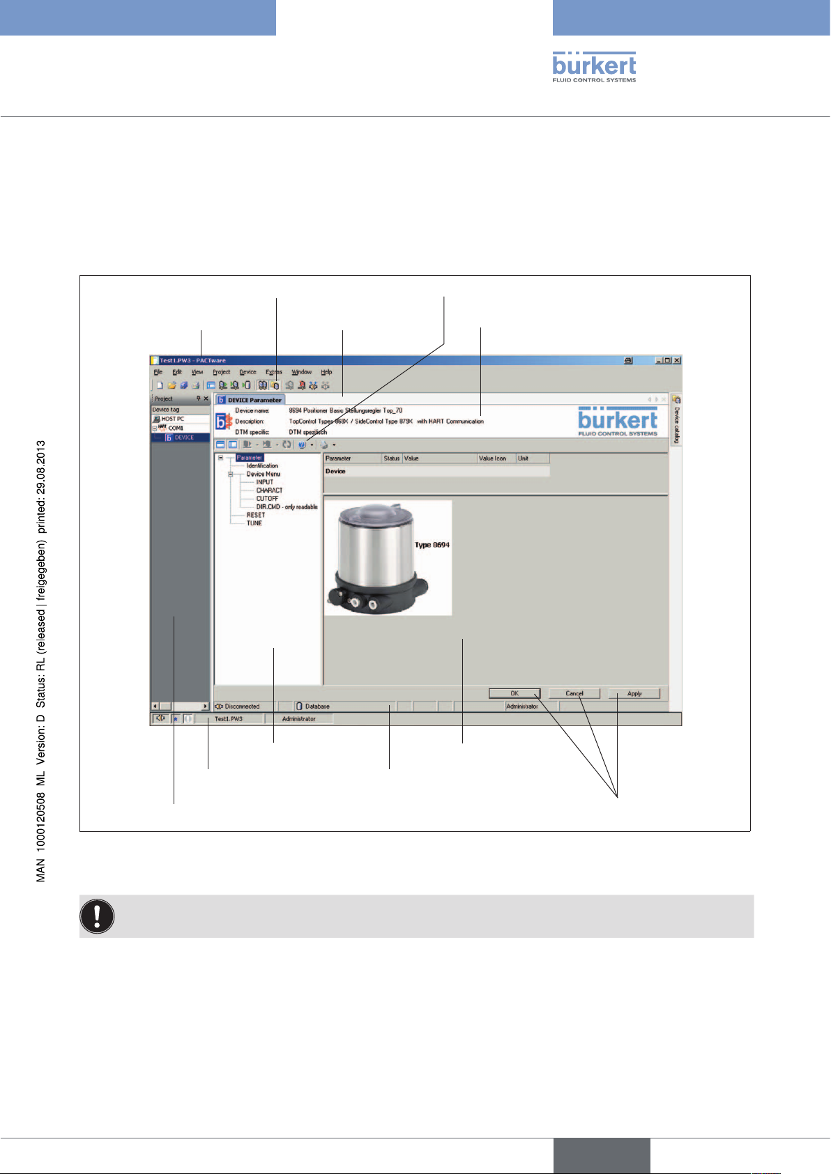
4.1. Overview of Screen Display
PACTware toolbar
PACTware window
DTM window
DTM toolbar
Identification area
Navigation area
PACTware status bar
Project window
Fig. 1: Overview of screen display
Many icons have Tooltips (brief explanation) which clarify the function.
DTM status bar
Work area
Buttons
9
English
Page 10

Software Tool - Positioner
Control and display elements
4.2. PACTware Control and Display Elements
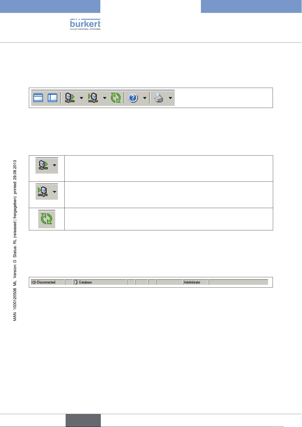
4.2.1. Toolbar
The toolbar is a combination of frequently required commands from the menu bar and project view. It is divided
into 4 sections.
Section 1 2 3 4
Fig. 2: PACTware toolbar
Section 1: Icons for project administration
Print the current project
Save the current project
Open an existing project
Create a new project
Fig. 3: PACTware toolbar - Section 1
Section 2: Icons for working with DTMs
Write current data to file
Write all data to the device
Read all data from the device
Edit current data
Fig. 4: PACTware toolbar - Section 2
Section 3: Icons for activating specific PACTware windows
10
Device catalog
Project view
Fig. 5: PACTware toolbar - Section 3
English
Page 11

Software Tool - Positioner
Control and display elements
Section 4: Icons for working with DTMs
Break the connection
Create a connection between the selected DTM and the field device
Delete the selected DTM from the project
Insert an additional DTM into the project at the selected position
Fig. 6: PACTware toolbar - Section 4
4.2.2. Status bar
The status bar contains information about the current state of the project being processed.
Fig. 7: Status bar
Meaning of the displays (from left to right):
• Connection status: Broken / connected
• Project has been changed (indicated by an asterisk)
• There are error messages. The icon flashes if the messages have not been displayed on the error monitor yet. A
Tooltip indicates the number of error messages present.
• Name of the project
• Active user role
More extensive explanations describing operation and how to create a project are available in the PACTware online help.
English
11
Page 12
Software Tool - Positioner
Control and display elements
4.3. Control and Display Elements of Bürkert DTMs
4.3.1. Toolbar
Fig. 8: DTM toolbar
The section on the left contains icons for the screen display:
Show and hide identification range
Show and hide navigation range
The second section is a combination of icons for device communication:
Read parameters from device
You can select here between: Read all parameters from the device
Read directory only
Read directory and subdirectories only
Write parameters to device
You can select here between: Write all parameters to device
Write directory only
Write directory and subdirectories only
Cyclic update of parameters in display (every 2 seconds)
Table 1: DTM icons
The two sections on the right contain the help function and the print function .
4.3.2. Status bar
The status bar contains information about the current state of the project being processed.
Fig. 9: Status bar
Meaning of the displays (from left to right):
• Connection status: Broken / connected
• Communication status
• Data source: Database / device
• Instance data record
• Device status
• Direct mode
• Device diagnostics
• User status
12
• Progress bar
English
Page 13
Software Tool - Positioner
Control and display elements
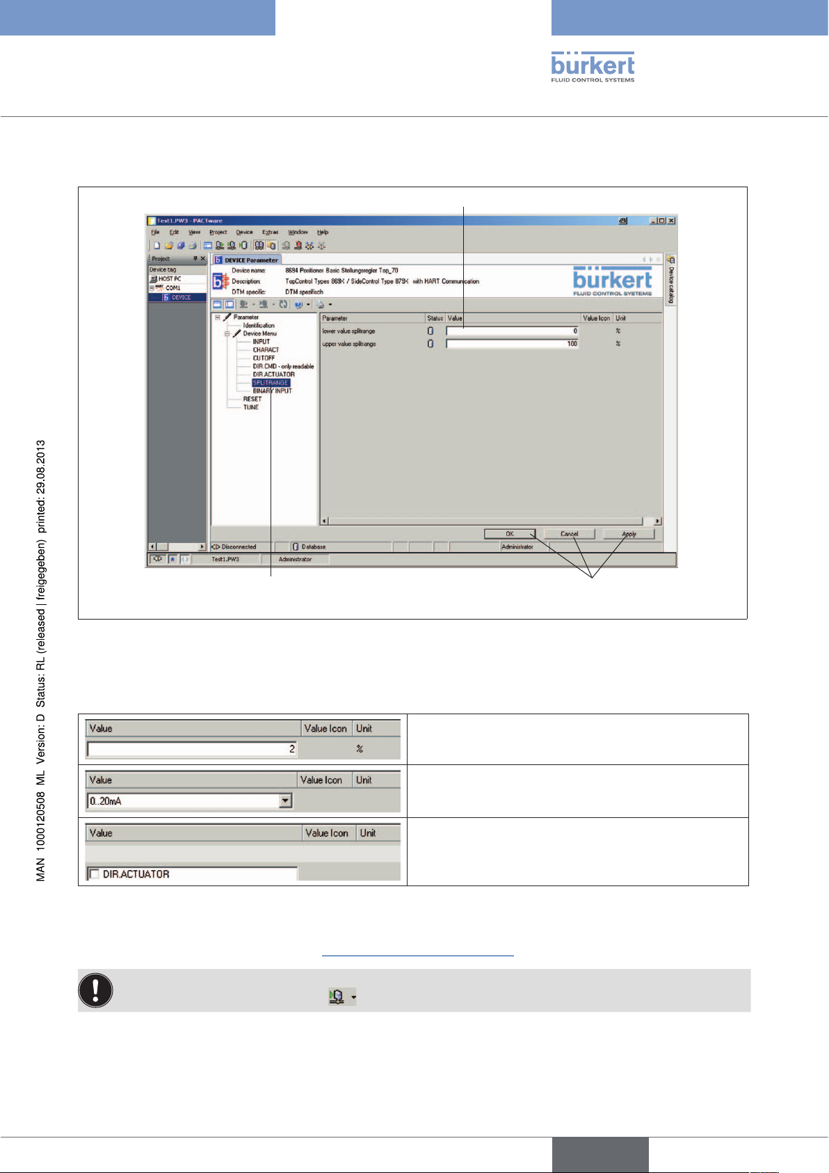
4.3.3. Navigation Area and Work Area
Value entry in the work area
Selection of function
in the navigation area
Fig. 10: Bürkert DTM screen display
Buttons for
data transfer
Functions are displayed in the navigation area.
When you click on the required function, it is highlighted in color and the corresponding (entry) screen appears:
Entry field for texts or values
Input via dropdown list
Select via checkbox
Table 2: Input screens
Parameters can be transferred to the database with the "Apply" or "OK" buttons. "Cancel" closes the DTM
window without saving (see also Section “4.3.4. Buttons for data transfer”).
You can save the project with the "File / Save" menu item.
To transfer to the device, select the
icon.
You can start the RESET and TUNE functions with the "Execute" and "Start X.TUNE" buttons respectively.
English
13
Page 14

4.3.4. Buttons for data transfer
Button Description
Software Tool - Positioner
Control and display elements
OK
Cancel
Apply
Table 3: Buttons for Data Transfer
The DTM window closes
Modified values are transferred to the database.
The DTM window closes
Modified values are not transferred to the database.
The DTM window remains open
Modified values are transferred to the database.
If you exit the program without saving the project, the data in the database is not saved.
You can save the project with the "File / Save" menu item.
To transfer to the device, select the
icon.
4.3.5. Icons
Modified value not saved or not written to device
Saved to database
Table 4: Icons
Device data
Invalid input value
Configuration or validation error with communication error
14
English
Page 15

Software Tool - Positioner
Installation
5. INSTALLATION
5.1. System Requirements
Hardware:
Processor: Intel Pentium/ AMD, at least 500 MHz
Working memory: At least 128 MB RAM
Hard disk: At least 250 MB free storage space
Graphics resolution: At least 1024 x 768
1 USB port to connect the Adapter USB-RS232, ID number 227093
Software:
Operating system Windows 2000/XP/Vista:
PACTware 3.6 + Microsoft .NET Framework 1.1 + .NET Framework 1.1 SP1
Operating system Windows XP/Vista/7:
PACTware 4.1 + Microsoft .NET Framework 2.0
Administrator rights are required for installation.
Windows must be rebooted after the installation. Then you must log into Windows under the same name,
because the installation is completed during the reboot.
5.2. Installing PACTware and DTMs
Select the appropriate PACTware version depending on the operating system in use, see chapter “5.1. System
Requirements”.
All installation programs are available on the Bürkert homepage and on CD.
Before the installation, exit all programs that are open.
15
English
Page 16

Software Tool - Positioner
Installation
5.2.1. PACTware version 3.6 and .NET Framework 1.1 including
SP1
Installation of PACTware requires the presence of software platform:
Microsoft .NET Framework 1.1 with Service Pack 1 (SP1)
Procedure to follow if “Microsoft .NET Framework 1.1 with Service Pack 1 (SP1)” is not present yet on the target
computer:
→ Download and / or open the Zip file (1000103878), which includes the Microsoft.NET 1.1 framework.
→ Start “Dotnetfx.exe”.
→ Download and / or open the Zip file (1000103880), which includes the Microsoft.NET 1.1 SP1 framework.
→ Start “NDP1.1sp1*.exe”.
Procedure PACTware Setup:
→ Download and / or open the Zip file (1000103690), which includes the PACTware setup and unzip in a tem-
porary directory.
→ Start “Setup.exe”.
Setup file “PACTware36setup.zip” contains
• the basic setup for PACTware 3.6 with online help in various languages
• the HART communication DTM for PACTware 3.6
• the Generic HART DTM (not required)
After you have selected the installation language, the installation is performed.
At this point the HART communications DTM can also be installed. It is required because communication with
Bürkert devices runs via the HART protocol and the physical layer has an RS232 interface rather than a HART
interface.
Optional components such as the manual are not installed here.
If PACTware 2.4, PACTware 3.0 or PACTware 3.5 are already installed, all passwords can be transferred for
PACTware 3.6 at the end of the installation.
During the installation, a program group is entered in the Windows start menu for the current user and a link to
PACTware 3.6 appears on the desktop.
16
Procedure DTM Setup:
→ Download and / or open the Zip file (1000121980), which includes the “Buerkert DTM Positioner“ setup, and
unzip in a temporary directory.
→ Start “Setup.exe” in the “Buerkert” subdirectory.
After you have selected the installation language, the installation is performed.
English
Page 17

Software Tool - Positioner
Installation
5.2.2. PACTware version 4.1 and .NET Framework 2.0
Download and / or open the Zip file “PACTware 4.1 SP1 Buerkert.zip“ and unzip in a temporary directory. This zip
file contains all the necessary installation components.
Installation of PACTware requires the presence of software platform:
Microsoft .NET Framework 2.0
Procedure to follow if “Microsoft .NET Framework 2.0“ is not present yet on the target computer:
→ Start setup
with a 64-bit operating system in directory dotNet\dotNET_20\x64
or with other operating systems in directory \dotNet\dotNET_20\x86.
Procedure PACTware Setup:
→ Start \PACTware\PACTware.msi.
Setup file contains:
• the basic setup for PACTware 4.1 with online help in various languages
• the HART communication DTM for PACTware 4.1
• the Generic HART DTM (not required)
After you have selected the installation language, the installation is performed.
At this point the HART communications DTM can also be installed. It is required because communication with
Bürkert devices runs via the HART protocol and the physical layer has an RS232 interface rather than a HART
interface.
Optional components such as the manual are not installed here.
If PACTware 2.4, PACTware 3.0, PACTware 3.5 or PACTware 3.6 are already installed, all passwords can be
transferred for PACTware 4.1 at the end of the installation.
During the installation, a program group is entered in the Windows start menu for the current user and a link to
PACTware 4.1 appears on the desktop.
English
17
Page 18
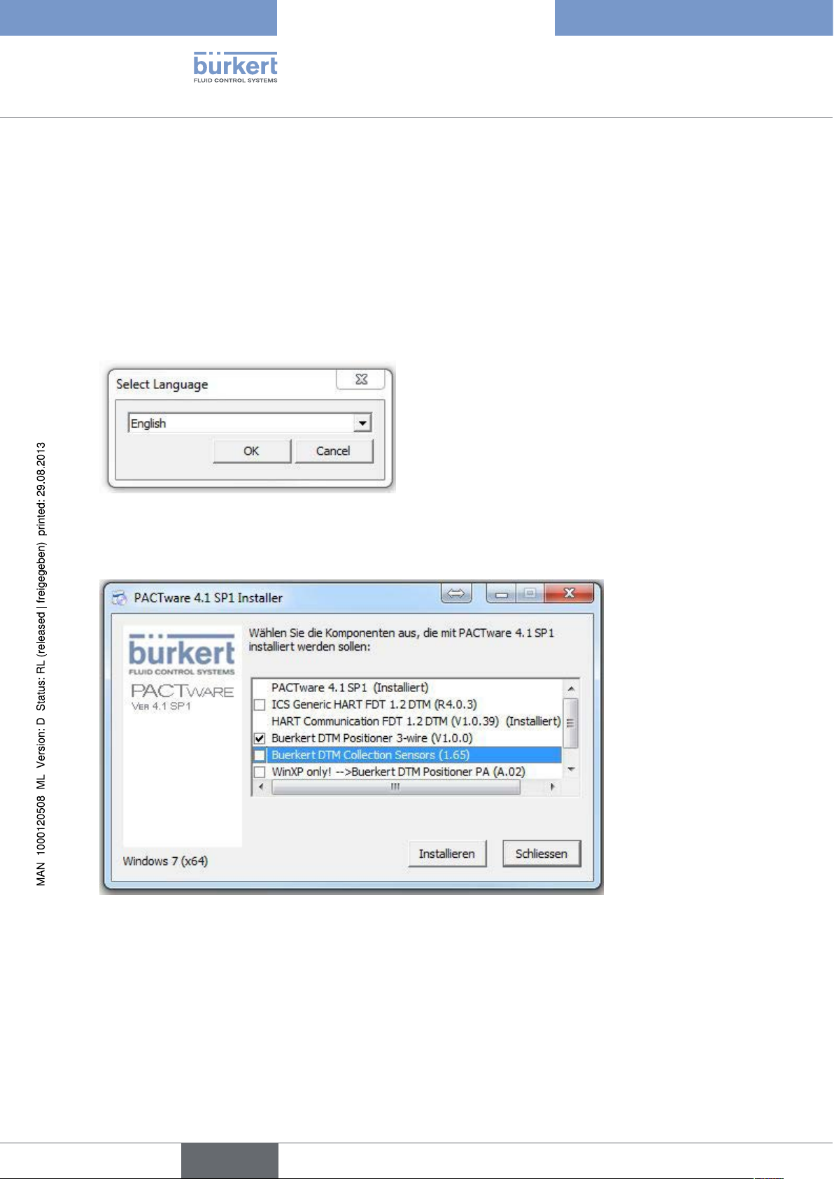
5.2.3. Bürkert device DTM
Procedure:
→ Start “Setup.exe” in the directory
AdditionalSetups\BuerkertDTMs\SETUP_Positioner_Typen_869X_879X_V1.0.0.
or alternative
→ Start “Setup.exe” in the master directory:
After you have selected the language,
Software Tool - Positioner
Installation
you can choose which components should be installed:
select PACTware 4.1 SP1 and Buerkert DTM Positioner 3-wire.
18
After you have selected the installation language, the installation is performed.
English
Page 19
Software Tool - Positioner
Operation and function
6. OPERATION AND FUNCTION
6.1. Starting PACTware
→ Start PACTware from the Windows start menu.
6.2. Creating a Project
6.2.1. General Description
AS a precondition for operating field devices, the device network must be represented in a PACTware project.
PACTware provides an area for this purpose where all installed DTMs are shown: The Device Catalog. Normally
the DTMs have the same name as the devices to facilitate control.
PACTware also provides a second area where the device network is represented: The Project Window. The
actual device network is represented in this project window by inserting DTMs from the device catalog. The
"HOST-PC" entry serves as the starting point for inserting a DTM. The required DTMs can be transferred from the
device catalog into the project window by double clicking or using drag and drop.
If you do not want the project window or device catalog to be visible, they can be activated in the menu
bar under "View".
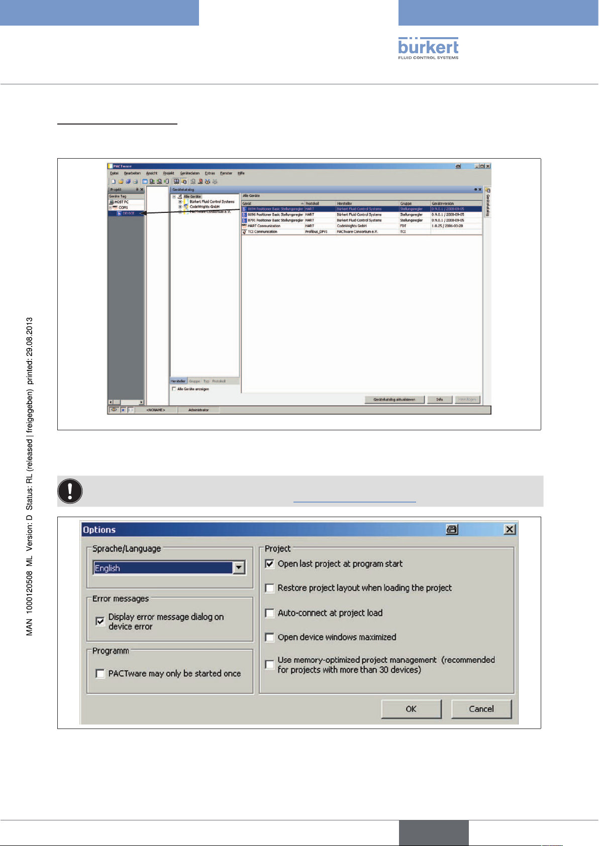
If the Bürkert device DTMs are not visible in the device catalog, the device catalog must first be updated.
To update the device catalog:
→ Switch to the "Device catalog" window with "View / Device catalog" (F3)
→ Click "Update device catalog"
→ Confirm the question "Create new PACTware device catalog?" with YES
→ After the device catalog is opened again, the Bürkert device DTMs are present; see “Fig. 11: Device catalog
with HART Comm DTM and Bürkert device DTMs”
English
19
Page 20

Project window PACTware windowDevice catalog
Software Tool - Positioner
Operation and function
Fig. 11: Device catalog with HART Comm DTM and Bürkert device DTMs
20
English
Page 21

Software Tool - Positioner
Operation and function
6.2.2. Creating a Project for Bürkert Positioners
To be able to communicate with positioners of types 8694, 8696, and 8791, first select HART communication
DTM and then a Bürkert device DTM:
1. To select a HART communication DTM:
→ Select "HART Communication, Fa. Codewrights GmbH" from the device catalog and double click or drag and
drop to integrate it into the project.
Fig. 12: To integrate a HART communication DTM:
→ Settings for the following parameters (mark communication DTM, then select the "Device / Parameter" menu
item with the menu bar or double click on the integrated communication DTM (COM1...n)):
Parameter
Fig. 13: Parameterizing a HART communication DTM
English
21
Page 22

Software Tool - Positioner
Operation and function
Communication interface: Extended HART modem
Serial interface: Port: COM1…n, depending on the connection
Baudrate: 9600
Parity: None
The remaining parameters can retain their default settings.
22
Fig. 14: Settings of the HART communications DTM
→ Click "OK" to transfer the set parameters to the database.
You can save the project with the "File / Save" menu item.
English
Page 23
Software Tool - Positioner
Operation and function
2. To select a Bürkert DTM:
Select "8694 Positioner TopControl Basic" or "8696 Positioner TopControl Basic" or "8791 Positioner SideControl Basic" from the device catalog and double click or drag and drop to integrate it into the project.
Fig. 15: Integrating a device
The project is now created and can be saved under "File / Save".
You can determine under PACTware "Tools / Options," in the "Project" area whether the last project
should be opened when the program starts (see “Fig. 16: PACTware options”).
Fig. 16: PACTware options
23
English
Page 24
Software Tool - Positioner
Operation and function
6.3. Basic Settings
The basic settings of the positioner are implemented at the factory.
Once the device DTMs are activated, the basic settings can be adapted user-specifically:
• Define the device identification
• Run the automatic adjustment X.TUNE
• Transfer parameters (see Chapter “6.4. Transferring Parameters”)
• Parameterization of functions (see Chapter “6.5. Parameterization”).
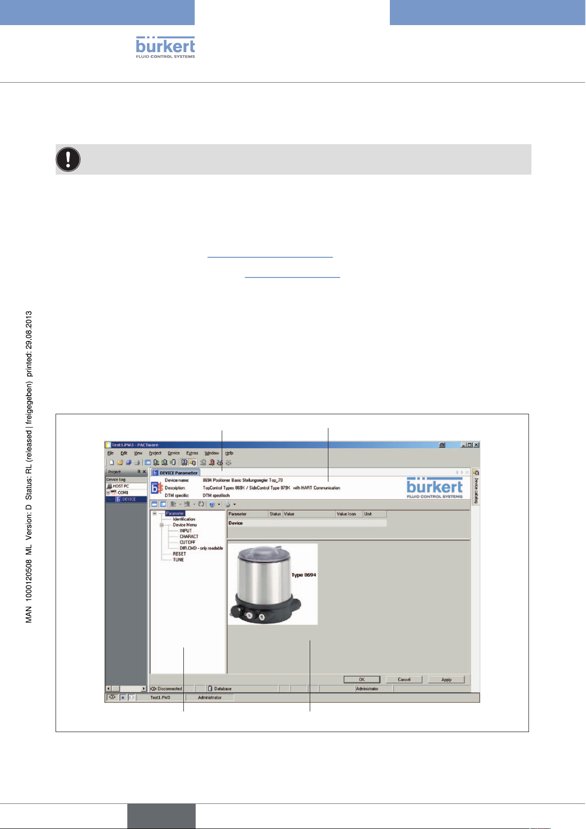
6.3.1. Activation of device DTMs
The DTM window is used for device identification, defining the basic settings, and parameterization of the device.
The window can be activated as follows:
• Double click on the required DTM in the project window or
• Right click and select "Parameters" or
• With the PACTware "Device / Parameters" menu item.
DTM window
Identification area
24
Fig. 17: DTM window
Navigation area
English
Work area
Page 25

Software Tool - Positioner
Operation and function
The navigation area contains the parameters and functions of the selected device in the folder structure
(see “Fig. 18: Navigation area”):
Identification: Enter user-specific device designations
Device menu: Parameterization of functions
Adding auxiliary functions
RESET: Reset to factory settings
TUNE: Automatic adjustment of the positioner to the relevant operating conditions
Parameter
Identification
Device menu
INPUT
CHARACT
CUTOFF
DIR.CMD
- only readable
RESET
TUNE
Description
Device indicator (TAG)
Date
Device Menu config. ADD.FUNCTION
Set-point value input
Select characteristic
Sealing function bottom
Sealing function top
Effective direction set-point value
RESET
Start X.TUNE
Enter user-specific device
designations
Adding auxiliary
functions
Device menu items for
parameterization of
functions
Reset to factory settings
Automatic adjustment of the
positioner to the relevant
operating conditions
Fig. 18: Navigation area
You can find a description and parameterization of individual functions in Sections “7. Parameterization of
Basic Functions” and “8. Configuring Auxiliary Functions”.
English
25
Page 26
Software Tool - Positioner
Operation and function
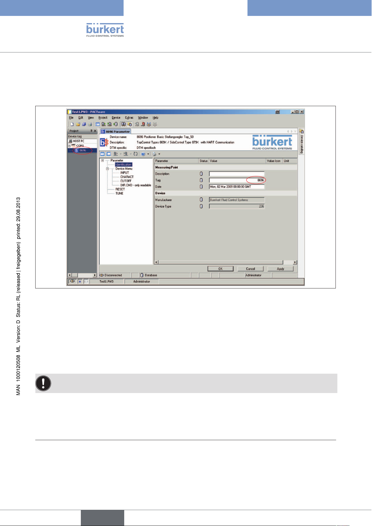
6.3.2. Device Identification
User-specific device data can be entered in the navigation area under the "Identification" item.
Fig. 19: Identification
Description: User-specific device description
1)
Tag: User-specific device indicator (TAG)
Date: User-specific date
→ Click "Apply" to transfer the modified parameters to the database.
You can save the project with the "File / Save" menu item.
1) As per HART specification
1)
26
English
Page 27
Software Tool - Positioner
Operation and function
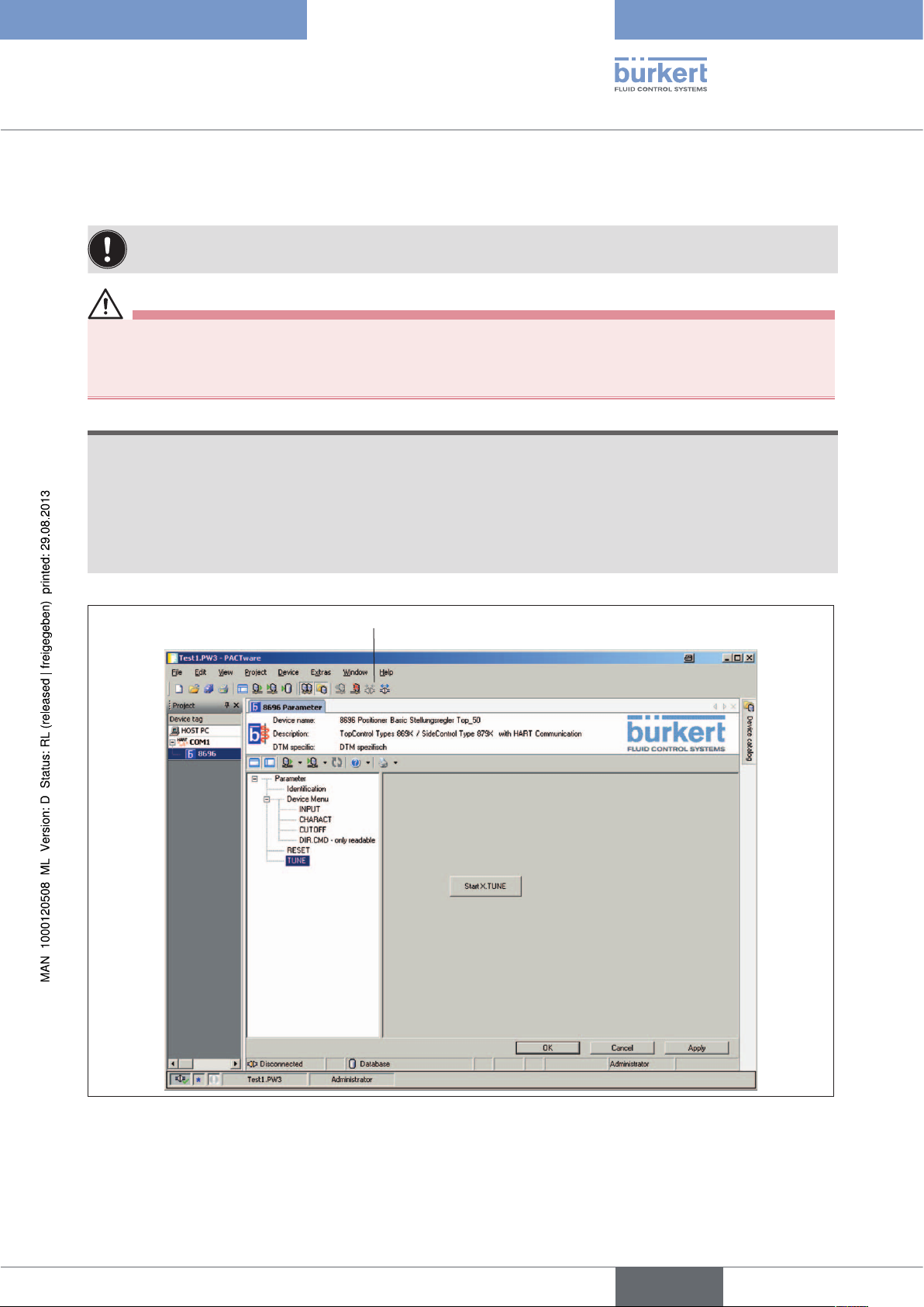
6.3.3. Running the Automatic Adjustment for X.TUNE
The X.TUNE function must be run for a function check of the positioner to adjust to specific local features.
WARNING!
While the X.TUNE function is running, the valve automatically moves from its current position!
• Never run X.TUNE while a process is running!
• Take appropriate measures to prevent the system / positioner from being unintentionally actuated!
NOTE!
Avoid maladjustment of the controller due to an incorrect compressed air supply or applied operating
medium pressure!
• Run X.TUNE whenever the compressed air supply (= pneumatic auxiliary energy) is available during subsequent operation.
• Run the X.TUNE function preferably without operating medium pressure to exclude interference caused by
flow forces.
Set up connection
Fig. 20: Starting X.TUNE
27
English
Page 28

Procedure:
To run X.TUNE, the positioner must be in the AUTOMATIC operating state
(DIP switch 4 = OFF).
→ Set up connection
→ Set up TUNE in the navigation area
Software Tool - Positioner
Operation and function
→ Start X.TUNE. To do this, click "Start X.TUNE"
2)
.
The progress of X.TUNE is shown in the communication software:
XTUNE start → POS 100 → ... → XTUNE end
When the automatic adjustment completes, the message "XTUNE end" appears
3)
.
The changes are automatically transferred to the positioner's memory (EEPROM) after the X.TUNE function is
successful.
After X.TUNE is complete, read the device parameter for processing from the positioner (see Chapter
“6.4.1. Reading Parameters from the Device”).
2) X.TUNE can also be started by pressing the key 1 on the positioner and holding it for 5 seconds.
3) If an error occurs, an error message appears (see Chapter “6.7. Error Messages”).
28
English
Page 29

Software Tool - Positioner
Operation and function
6.4. Transferring Parameters
DTM: Read parameters
from the device
DTM: Write parameters
to the device
Set up connection
Break connection
Fig. 21: Transferring parameters
6.4.1. Reading Parameters from the Device
Procedure:
→ Connect
→ Read parameters from device
with option to select: Read all parameters from device
Read directory only
Read directory and subdirectories only
If the parameters are transferred using the PACTware "Device / Load from device" menu item or using the PACTware
icon, all parameters are read from the device.
29
English
Page 30

Software Tool - Positioner
Operation and function
6.4.2. Write parameters to the device
NOTE!
If changes are made and transferred with the "Write all parameters to device" function, it is possible that
parameters in the device will be unintentionally overwritten!
• Read the current device data before you make the changes or
• transfer only the modified parameters by using the selection options "Write directory only" or "Write directory
and subdirectories only".
Procedure:
→ Connect
→ Write parameters to device
with option to select: Write all parameters to device
Write directory only
Write directory and subdirectories only
If the parameters are transferred using the PACTware "Device / Store to device" menu item or using the PACTware
icon, all (!) parameters will be written to the device.
More extensive explanations describing operation and how to create a project are available in the PACTware online help. For start-up and parameterization, refer also to the operating instructions for the relevant device.
6.5. Parameterization
A distinction is made in parameterization between offline and online mode.
Offline mode
In Offline mode the project can be created and parameters can be changed and saved without devices connected. Then the data can be saved later to connected devices in Online mode.
Online mode
In Online mode the device to be parameterized must be connected and ready for operation. Selecting the corresponding DTM by right clicking and selecting the "Connect" command or with PACTware menu "Device /
Connect" causes Online mode to be prepared.
30
English
Page 31

Software Tool - Positioner
Operation and function
6.5.1. Parameterizing functions
Value entry in the work area
Selection of function
in the navigation area
Fig. 22: Parameterizing functions
Procedure:
Buttons
→ Select the function in the navigation area (highlighted in color)
→ Select or enter the values in the work area
→ Modified values can be transferred to the database with the "Apply" or "OK" button. If you exit the function with
the "Cancel" button, the changes are not transferred.
You can save the project with the "File / Save" menu item.
Notes on DIP switches:
The switching positions of the DIP switches in the positioner take precedence over the communication
software, i.e. settings of the sealing function (CUTOFF) or correction characteristic (CHARACT) that are
modified through the communication software are only active if the corresponding DIP switch in the positioner is set to ON. The effective direction (DIR.CMD) can only be changed with DIP switches.
All setting that are made must still be transferred to the device (see Chapter “6.4. Transferring Parameters”).
English
31
Page 32

Software Tool - Positioner
Operation and function
6.6. Overview of Basic Functions and Auxiliary
Functions
6.6.1. Basic Functions
The following basic functions are created as device menu items in the navigation area in the factory:
INPUT
CHARACT
CUTOFF
DIR.CMD
RESET
TUNE
The parameterization and description of basic functions may be found in Section "7. Parameterization of
Basic Functions".
Entry of the unit signal input for the set-point value
Selection of the transfer characteristic between input signal and stroke (correction
characteristic)
Sealing function for positioner
Effective direction between input signal and set-point position
Reset to factory settings
Automatic adjustment of the positioner to the relevant operating conditions
6.6.2. Auxiliary functions
The following auxiliary functions can be added to the device menu:
DIR.ACTUATOR
SPLITRANGE
X.LIMIT
X.TIME
X.CONTROL
SAFE POSITION
SIGNAL ERROR
BINARY INPUT
OUTPUT
Assignment of the aeration state of the actuator chamber to the actual position
Signal split range; input signal as % for which the valve runs through the entire stroke
range.
Limit the mechanical stroke range
Limit the control speed
Parameterize the positioner
Definition of the safety position
Configuration of signal level fault detection
Activation of the binary input
Configuration of the output (only with auxiliary board for analog feedback)
32
The configuration, parameterization, and description of auxiliary functions may be found in Section “8.
Configuring Auxiliary Functions”.
English
Page 33

Software Tool - Positioner
Operation and function
6.7. Error Messages
6.7.1. Error messages while the X.TUNE function is running
Display Cause of fault Remedial action
ERR 1:
No compressed air
ERR 2:
Compressed air failed
during X.TUNE
ERR 3:
Control system
deaeration side leaking
ERR 4:
Control system aeration
side leaking
Table 5: Error messages for X.TUNE
No compressed air connected Connect compressed air
Compressed air failure while the X.TUNE
function was running
Actuator or control system deaeration side
leaking
Control system aeration side leaking Not possible, device defective
Check compressed air
compressed air supply
Not possible, device defective
English
33
Page 34

Software Tool - Positioner
Parameterization of Basic Functions
7. PARAMETERIZATION OF BASIC FUNCTIONS
7.1. Overview of Basic Functions
The following basic functions are created as device menu items in the navigation area in the factory:
INPUT
CHARACT
CUTOFF
DIR.CMD
RESET
TUNE
Entry of the unit signal input for the set-point value
Selection of the Transfer Characteristic between Input Signal and Stroke (Correction Characteristic)
Sealing function for positioner
Effective direction between input signal and set-point position
Reset to factory settings
Automatic adjustment of the positioner to the relevant operating conditions
7.2. Basic Functions
Parameterization and transfer of parameters are described in Sections “6.5. Parameterization” and “6.4.
Transferring Parameters”.
NOTE!
If changes are made and transferred with the "Write all parameters to device" function, it is possible that
parameters in the device will be unintentionally overwritten!
• Read the current device data before you make the changes or
• transfer only the modified parameters by using the selection options "Write directory only" or "Write directory
and subdirectories only".
34
Modified values can be transferred to the database with the "Apply" or "OK" button. If you exit the function
with the "Cancel" button, the changes are not transferred.
You can save the project with the "File / Save" menu item.
7.2.1. INPUT -
Enter the input signal
Under this menu option, enter the unit signal used for the set-point value.
→
Factory setting: 4 – 20 mA
INPUT
Fig. 23: INPUT function
setpoint input
4 – 20 mA
4 – 20 mA
0 – 20 mA
English
Page 35

Software Tool - Positioner
Parameterization of Basic Functions
7.2.2. CHARACT -
Select the transfer characteristic between input signal
(position set-point value) and stroke
Characteristic (customer-specific characteristic)
Use this function to select a transfer characteristic with reference to set-point value (nominal position) and valve
stroke to correct the flow-rate or operating characteristic.
Factory setting: linear
The switching position of the DIP switches in the positioner takes precedence over the communication
software, i.e. settings of the correction characteristic (CHARACT) that are modified through the communication software are only active if the corresponding DIP switch in the positioner is set to ON.
CHARACT
Fig. 24: CHARACT function
select characteristic curve
Select characteristic: Description:
linear Linear characteristic
1 : 25 Equal percentage characteristic 1:25
1: 33 Equal percentage characteristic 1:33
1 : 50 Equal percentage characteristic1:50
25 : 1 Inversely equal percentage characteristic 25:1
33 : 1 Inversely equal percentage characteristic 33:1
55 : 1 Inversely equal percentage characteristic 50:1
4)
FREE
User-defined characteristic, freely programmable with nodes
linear
linear
1 : 25
1 : 33
1 : 50
25 : 1
33 : 1
50 : 1
FREE
4) For information on entering nodes, see “Entering the freely programmable characteristic”
English
35
Page 36

Software Tool - Positioner
Parameterization of Basic Functions
The flow characteristic kV = f(s) indicates the flow-rate of a valve, expressed by the value kV as a function of the
stroke s of the actuator spindle. It is determined by the design of the valve seat and the seat seal. In general two
types of flow characteristics are implemented, the linear and the equal percentage.
In the case of linear characteristics, equal k
= n
(dk
⋅ds).
V
lin
In the case of an equal percentage characteristic, an equal percentage change of the k
value changes dkV are assigned to equal stroke changes ds.
V
value corresponds to a
V
stroke change ds.
(dk
V/kV
= n
eqlprct
⋅ds).
The operating characteristic Q = f(s) specifies the correlation between the volumetric flow Q in the installed
valve and the stroke s. This characteristic has the properties of the pipelines, pumps and consumers. It therefore
exhibits a form which differs from the flow characteristic.
Standardized valve stroke [%]
Position set-point value
[%]
Fig. 25: Characteristic
In the case of control tasks for closed-loop control systems it is usually particular demands which are placed on the
course of the operating characteristic, e.g. linearity. For this reason it is occasionally necessary to correct the course
of the operating characteristic in a suitable way. For this purpose the positioner features a transfer element which
implements different characteristics. These are used to correct the operating characteristic.
Equal percentage characteristics 1:25, 1:33, 1:50, 25:1, 33:1, and 50:1 as well as a linear characteristic can be
set. A characteristic can be freely programmed using nodes.
36
English
Page 37

Software Tool - Positioner
Parameterization of Basic Functions
Entering the freely programmable characteristic
The characteristic is defined by 21 nodes distributed uniformly over the position set-point values ranging from 0 –
100%. They are spaced at intervals of 5%. A freely selectable stroke (adjustment range 0 – 100%) is assigned to
each node. The difference between the stroke values of two adjacent nodes must not be greater than 20%.
CHARACT
select characteristic curve
CHARACTERISTIC CURVE
0%
5%
10%
15%
20%
25%
30%
35%
40%
45%
50%
55%
60%
65%
70%
75%
80%
85%
90%
95%
100%
FREE
0.0
5.0
10.0
15.0
20.0
25.0
30.0
35.0
40.0
45.0
50.0
55.0
60.0
65.0
70.0
75.0
80.0
85.0
90.0
95.0
100.0
%
%
%
%
%
%
%
%
%
%
%
%
%
%
%
%
%
%
%
%
%
Fig. 26: CHARACT FREE function
Procedure:
→ To enter the characteristic points (function values) in the dropdown list, select the FREE sub-menu option.
Another sub-menu (CHARACTERISTIC CURVE) opens, where the individual nodes are listed (as %).
→ Select the individual nodes and enter the required values numerically.
English
37
Page 38

Example of a programmed characteristic
Valve stroke [&]
100
90
80
70
60
50
Software Tool - Positioner
Parameterization of Basic Functions
40
30
20
10
0
10 20 30 40 50 60 70 80 90 100
4 – 20 mA
0 – 20 mA
Fig. 27: Example of a programmed characteristic
Unit signal [%]
38
English
Page 39

Software Tool - Positioner
Parameterization of Basic Functions
7.2.3. CUTOFF -
Sealing Function for the Positioner
This function causes the valve to be sealed outside the control range.
You can enter the limits for the position set-point value here as a percentage. When these limits are reached, the
actuator will be fully deaerated or aerated respectively.
Control mode resumes at a hysteresis of 1%.
Factory setting: close tight low = 2%;
close tight high = 98%
The switching position of the DIP switches in the positioner takes precedence over the communication
software, i.e. settings of the sealing function (CUTOFF) that are modified through the communication
software are only active if the corresponding DIP switch in the positioner is set to ON.
CUTOFF
Fig. 28: CUTOFF function
Valve stroke [%]
Adjustable from 75 – 100%
close tight low
close tight high
98
%
2
%
Adjustable from 0 – 25%
Fig. 29: CUTOFF graph
Set-point value
[%]
39
English
Page 40

Software Tool - Positioner
Parameterization of Basic Functions
7.2.4. DIR.CMD -
Effective Direction of the Positioner Set-Point Value
You can use this function to adjust the effective direction between the input signal (INPUT) and the nominal
position of the drive.
Factory setting: rise
The effective direction (DIR.CMD) can only be changed with DIP switches in the positioner.
DIR.CMD
- only readable
Fig. 30: DIR.CMD function
Nominal position
Fig. 31: DIR.CMD graph
direction setpoint
increasing
decreasing
Input signal
(INPUT)
rise
40
English
Page 41

Software Tool - Positioner
Parameterization of Basic Functions
7.2.5. RESET -
Reset to Factory Settings
This function can be used to reset the positioner to the factory settings.
RESET
Fig. 32: DIR.CMD function
Procedure:
RESET
Execute
→ Connect
→ Click "Execute".
7.2.6. TUNE -
Automatic Adjustment of the Positioner to the Relevant
Operating Conditions
A description of the TUNE function may be found in Section “6.3.3. Running the Automatic Adjustment for
X.TUNE”.
English
41
Page 42

Software Tool - Positioner
Configuring Auxiliary Functions
8. CONFIGURING AUXILIARY FUNCTIONS
Modified values can be transferred to the database with the "Apply" or "OK" button. If you exit the function
with the "Cancel" button, the changes are not transferred.
You can save the project with the "File / Save" menu item.
8.1. Adding auxiliary functions
Procedure:
→ When you select the "Device Menu" function in the navigation area (highlighted in color), the auxiliary func-
tions appear in the work area.
→ Activate the auxiliary functions you need in the checkboxes. They will be added to the folder structure in the
navigation area immediately
Parameterization is performed in the relevant function.
42
Fig. 33: Configuring auxiliary functions
8.2. Removing Auxiliary Functions
Procedure:
→ When you select the "Device Menu" function in the navigation area (highlighted in color), the auxiliary func-
tions appear in the work area.
→ Deactivate the auxiliary functions you do not need in the checkboxes. They will be removed from the folder
structure in the navigation area immediately.
English
Page 43

Software Tool - Positioner
Configuring Auxiliary Functions
8.3. Parameterization of Auxiliary Functions
Parameterization and transfer of parameters are described in Sections “6.5. Parameterization” and “6.4.
Transferring Parameters”.
NOTE!
If changes are made and transferred with the "Write all parameters to device" function, it is possible that
parameters in the device will be unintentionally overwritten!
• Read the current device data before you make the changes or
• transfer only the modified parameters by using the selection options "Write directory only" or "Write directory
and subdirectories only".
Modified values can be transferred to the database with the "Apply" or "OK" button. If you exit the function
with the "Cancel" button, the changes are not transferred.
You can save the project with the "File / Save" menu item.
8.4. Overview of Possible Auxiliary Functions
DIR.ACTUATOR
SPLITRANGE
X.LIMIT
X.TIME
X.CONTROL
SAFE POSITION
SIGNAL ERROR
BINARY INPUT
OUTPUT
Assignment of the aeration state of the actuator chamber to the actual position
Signal split range; input signal as a % for which the valve runs through the entire stroke
range.
Limit the mechanical stroke range
Limit the control speed
Parameterize the positioner
Definition of the safety position
Configuration of signal level fault detection
Activation of the binary input
Configuration of the outputs (only with auxiliary board for analog feedback)
English
43
Page 44

Software Tool - Positioner
Configuring Auxiliary Functions
8.5. Auxiliary Functions
NOTE!
If changes are made and transferred with the "Write all parameters to device" function, it is possible that
parameters in the device will be unintentionally overwritten!
• Read the current device data before you make the changes or
• transfer only the modified parameters by using the selection options "Write directory only" or "Write directory
and subdirectories only".
Modified values can be transferred to the database with the "Apply" or "OK" button. If you exit the function
with the "Cancel" button, the changes are not transferred.
You can save the project with the "File / Save" menu item.
8.5.1. DIR.ACTUATOR -
Effective Direction of the Actuator Drive
Use this function to set the effective direction between the aeration state of the actuator and the actual position.
Factory setting: rise
DIR. ACTUATOR
Fig. 34: DIR. ACTUATOR function
Rise: Direct effective direction (deaerated → 0%; aerated 100%)
Case: Inverse effective direction (deaerated → 100%; aerated 0%)
Actual
position
direction actual value
increasing
rise
rise
fall
44
deaerated
Fig. 35: DIR.ACTUATOR graph
English
decreasing
aerated
Aeration
state
Page 45

Software Tool - Positioner
Configuring Auxiliary Functions
8.5.2. SPLITRANGE -
Signal Split Range
Minimum and maximum values of the input signal as a % for which the valve runs through the entire stroke range.
Factory setting: Lower signal range split = 0%; Upper signal range split = 100%
%
100
0
%
SPLITRANGE
lower value split range
upper value split range
Fig. 36: SPLITRANGE function
Lower value split range: Input the minimum value of the input signal as a %
Adjustment range: 0 – 75%
Upper value split range: Input the maximum value of the input signal as a %
Adjustment range: 25 – 100%
Use this function to limit the position set-point value range of the positioner by specifying a minimum and a
maximum value. This makes it possible to divide a unit signal range that is used (4 – 20 mA, 0 – 20 mA) into
several positioners (without or with overlapping). This allows several valves to be used alternately or, in the case
of overlapping set-point value ranges, simultaneously as actuators.
To split a unit signal range into two set-point value ranges:
Valve stroke [%]
Set-point value [mA]
(INPUT)
Set-point value range
Positioner 1
Fig. 37: SPLTRNG graph
Set-point value range
Positioner 2
45
English
Page 46

Software Tool - Positioner
Configuring Auxiliary Functions
8.5.3. X.LIMIT -
Limiting the Mechanical Stroke Range
This function limits the (physical) stroke to specified % values (lower and upper). In doing so, the stroke range of
the limited stroke is set equal to 100%. If the limited stroke range is left during operation, negative actual positions or actual positions greater than 100% are shown.
Factory setting: Lower position limit = 0%, upper position limit = 100%
%
100
0
%
X.LIMIT
Fig. 38: X.LIMIT function
lower position limit
upper position limit
Adjustment ranges:
Lower position limit: 0 – 50% of the entire stroke
Upper position limit: 50 – 100% of the entire stroke
The minimum distance between the upper and lower stroke limit is 50%. Therefore if one value is entered with a
minimum distance of < 50% the other value is adjusted automatically.
Limited
stroke (%)
Physical
stroke (%)
Unlimited
stroke
Limited
stroke
Control range in
AUTOMATIC mode
46
Adjustment range in MANUAL mode
Set-point value
[mA] (INPUT)
Fig. 39: X.LIMIT graph
English
Page 47

Software Tool - Positioner
Configuring Auxiliary Functions
8.5.4. X.TIME -
Limiting the Control Speed
Use this function to specify the opening and closing times for the entire stroke and thereby limit control speeds.
When the X.TUNE function is running, the minimum opening and closing time for the entire stroke is automatically entered for Open and Close. Therefore, movement can be at maximum speed.
Factory setting: values determined at the factory by the X.TUNE function
If the control speed will be limited, values can be input for Open and Close which are between the minimum
values determined by the X.TUNE and 60 seconds.
X.TIME
valve timeopen
valve timeclose
Fig. 40: X.TIME function
Valve timeopen: Opening time for entire stroke (in seconds)
Adjustment range: 1 – 60 seconds
Valve timeclose: Closing time for entire stroke (in seconds)
Adjustment range: 1 – 60 seconds
Effect of limiting the opening speed when there is a jump in the set-point value
Valve stroke [%]
Set-point
value
1
1
Fig. 41: X.TIME graph
Actual value
t
Open
47
English
Page 48

Software Tool - Positioner
Configuring Auxiliary Functions
8.5.5. X.CONTROL -
Parameterization of the Positioner
Use this function to set the parameters for the positioner (dead band and amplification factors (kp)).
X.CONTROL
Fig. 42: X.CONTROL menu item
Deadband: Insensitivity range of the positioner
Entry for the deadband as a % in reference to the scaled stroke range;
i.e. X.LIMIT upper stroke limit - X.LIMIT lower stroke (see auxiliary function X.LIMIT).
deadband
kp open
kp close
1.0
%
1
1
This function causes the controller to respond only beginning at a specific control difference. This function saves
wear on the solenoid valves in the positioner and the pneumatic actuator.
If the auxiliary function X.CONTROL is in the main menu while X.TUNE (Autotune of the positioner) is
running, the deadband is determined automatically depending on the friction behavior of the actuator drive.
The value determined in this way is an approximate value. You can re-adjust it manually.
Xd1‘
Position setpoint value
Control
difference
Xd1
Position
Dead band
Xd1
to the
controller
Xd1‘
actual value
Fig. 43: X.CONTROL graph
48
Open/close amplification factor: Parameters for the positioner
Open amplification factor: Amplification factor of the positioner (for closing the valve)
Close amplification factor: Amplification factor of the positioner (for opening the valve)
English
Page 49

Software Tool - Positioner
Configuring Auxiliary Functions
8.5.6. SAFE POSITION -
Definition of the Safe Position
This function specifies the actuator safety position which is approached at defined signals.
The set safety position is only approached if there is a corresponding signal at the binary input (for configuration see BINARY INPUT) or if a signal error occurs (for configuration see SIGNAL ERROR).
If the mechanical stroke range is limited with the X.LIMIT function, only safety positions within these limits
can be approached.
This function is executed in AUTOMATIC mode only.
SAFE POSITION
safety position
%
0
Fig. 44: SAFE POSITION function
8.5.7. SIGNAL ERROR -
Configuration of signal level fault detection
The SIGNAL ERROR function is used to detect a fault on the input signal.
Fault detection
Fault detection can be selected for a 4 – 20 mA signal only:
Fault if input signal ≤ 3.5 mA (± 0.5% of final value, hysteresis 0.5% of final value)
If 0 – 20 mA is selected, sensor break detection cannot be selected.
SIGNAL ERROR
Fig. 45: SIGNAL ERROR -1 function
After "setpoint error detection” ON is selected, a new dropdown list appears:
setpoint error detection
OFF
OFF
ON
SIGNAL ERROR
Fig. 46: SIGNAL ERROR -2 function
setpoint error detection
safety position if setpoint error
ON
OFF
OFF
ON
49
English
Page 50

Software Tool - Positioner
Configuring Auxiliary Functions
A signal error is indicated on the device by the red LED for "setpoint error detection” ON.
Safety position for sensor break ON:
The following configurations can occur with "safety position if setpoint error” ON:
Active SAFE POSITION
If a fault is detected, the drive moves to the lower SAFE POSITION set position.
Inactive SAFE POSITION
If a fault is detected, the drive moves to the end position which it would assume in the isolated state.
8.5.8. BINARY INPUT -
Activation of the binary input
This function activates the binary input.
The following settings can be implemented for this:
• Approach the safety position
or
• Switching over the MANUAL/AUTOMATIC operating mode
BINARY INPUT
Fig. 47: BINARY INPUT function
Safety position
Approach the safety position.
Active SAFE POSITION function
the drive moves to the lower SAFE POSITION set position.
Inactive SAFE POSITION
The drive moves to the end position which it would assume in the isolated state.
binary input function
binary input type
safety position
safety position
switch manual-auto
normally open
normally open
normally closed
50
Switch manual-auto
Switch over the operating state to MANUAL or AUTOMATIC.
Binary input = 0 →AUTOMATIC operating state
Binary input = 1 →MANUAL operating state
If switching over the operating mode is selected, you can no longer switch the operating mode with DIP switch 4.
English
Page 51

Software Tool - Positioner
Configuring Auxiliary Functions
8.5.9. OUTPUT (optional) -
Configuration of the analog output
The OUTPUT menu item only appears in the selection of auxiliary functions if the positioner has an analog output
(optional) or if no parameters have been read in yet.
The analog output can be used for feedback of the current position or of the set-point value to the control center.
OUTPUT
Fig. 48: OUTPUT function
Standard signal output: parameter Position Output of the current position
Standard signal output: type 4 – 20 mA Selection of the unit signal
standard signal output: parameter
standard signal output: type
Set-point value Output of the set-point value
0 – 20 mA
Position
Position
Setpoint
4 – 20 mA
4 – 20 mA
0 – 20 mA
English
51
Page 52

Software Tool - Positioner
Deinstallation of PACTware/ DTMs
9. DEINSTALLATION OF PACTWARE/ DTMS
9.1. Deinstallation process
Procedure:
→ Select the "Software" item in the system control (via "Start / Settings / System Control").
→ Select "HART Communication DTM" or "Buerkert Positioner DTM" from the "PACTware" list and click "Change /
remove".
→ Run the deinstallation as suggested by the wizard and complete the process by rebooting Windows.
52
English
Page 53

Software Tool - Positioner
Kommunikationssoftware (Software Tool) für Positioner
Inhalt
1. ERGÄNZENDE BEDIENUNGSANLEITUNG .........................................................................................................................56
1.1. Darstellungsmittel ..............................................................................................................................................................56
2. ALLGEMEINE HINWEISE ..............................................................................................................................................................57
2.1. Kontaktadressen .................................................................................................................................................................57
2.2. Informationen im Internet ...............................................................................................................................................57
3. PRODUKTBESCHREIBUNG ........................................................................................................................................................58
3.1. Erforderliche Komponenten ..........................................................................................................................................58
3.1.1. Windows 2000, XP, Vista .....................................................................................................................58
3.1.2. Windows XP, Vista, 7 .............................................................................................................................58
3.2. Begriffsdefinitionen PACTware / FDT / DTM .......................................................................................................58
4. BEDIEN- UND ANZEIGEELEMENTE .......................................................................................................................................59
4.1. Übersicht Bildschirmanzeige .......................................................................................................................................59
4.2. Bedien- und Anzeigeelemente PACTware ............................................................................................................60
4.2.1. Symbolleiste .............................................................................................................................................60
4.2.2. Statusleiste ...............................................................................................................................................61
4.3. Bedien- und Anzeigeelemente der Bürkert-DTMs ...........................................................................................62
4.3.1. Symbolleiste .............................................................................................................................................62
4.3.2. Statusleiste ...............................................................................................................................................62
4.3.3. Navigationsbereich und Arbeitbereich ...............................................................................................63
4.3.4. Schaltflächen zur Datenübernahme .................................................................................................... 64
4.3.5. Symbole .....................................................................................................................................................64
5. INSTALLATION ...................................................................................................................................................................................65
5.1. Systemanforderungen ......................................................................................................................................................65
5.2. PACTware und DTMs installieren ...............................................................................................................................65
5.2.1. PACTware Version 3.6 und .NET Framework 1.1 einschließlich SP1 ........................................66
5.2.2. PACTware Version 4.1 und .NET Framework 2.0 ............................................................................67
5.2.3. Bürkert Geräte DTM ...............................................................................................................................68
deutsch
53
Page 54

Software Tool - Positioner
6. BEDIENUNG UND FUNKTION ...................................................................................................................................................69
6.1. PACTware starten ...............................................................................................................................................................69
6.2. Projekt erstellen ..................................................................................................................................................................69
6.2.1. Allgemeine Beschreibung .....................................................................................................................69
6.2.2. Projekt für Bürkert Positioner erstellen ...............................................................................................71
6.3. Grundeinstellungen ...........................................................................................................................................................74
6.3.1. Aktivieren der Geräte-DTM ...................................................................................................................74
6.3.2. Geräteidentifikation .................................................................................................................................76
6.3.3. Ausführen der automatischen Anpassung X.TUNE ................................................................. 77
6.4. Parameter übertragen ......................................................................................................................................................79
6.4.1. Parameter aus dem Gerät lesen .......................................................................................................... 79
6.4.2. Parameter in das Gerät schreiben ......................................................................................................80
6.5. Parametrierung ....................................................................................................................................................................80
6.5.1. Parametrieren von Funktionen ..............................................................................................................81
6.6. Übersicht Grundfunktionen und Zusatzfunktionen ..........................................................................................82
6.6.1. Grundfunktionen ......................................................................................................................................82
6.6.2. Zusatzfunktionen......................................................................................................................................82
6.7. Fehlermeldungen ................................................................................................................................................................83
6.7.1. Fehlermeldungen bei der Durchführung der Funktion X.TUNE ..................................................83
7. PARAMETRIEREN GRUNDFUNKTIONEN ............................................................................................................................... 84
7.1. Übersicht Grundfunktionen ...........................................................................................................................................84
7.2. Grundfunktionen .................................................................................................................................................................84
7.2.1. INPUT -
Eingabe des Eingangssignals ..............................................................................................................84
7.2.2. CHARACT -
Auswahl der Übertragungskennlinie zwischen Eingangssignal (Stellungs-Sollwert) und Hub .
85
54
7.2.3. CUTOFF -
Dichtschließfunktion für den Positioner ..............................................................................................89
7.2.4. DIR.CMD -
Wirkrichtung (Direction) des Positioner-Sollwertes ........................................................................ 90
7.2.5. RESET -
Rücksetzen auf die Werkseinstellungen ............................................................................................91
7.2.6. TUNE -
Automatische Anpassung des Positioners an die jeweiligen Betriebsbedingungen ..............91
deutsch
Page 55

Software Tool - Positioner
8. KONFIGURIEREN DER ZUSATZFUNKTIONEN .................................................................................................................92
8.1. Zusatzfunktionen hinzufügen.......................................................................................................................................92
8.2. Zusatzfunktionen entfernen ..........................................................................................................................................92
8.3. Parametrieren von Zusatzfunktionen .......................................................................................................................... 93
8.4. Übersicht möglicher Zusatzfunktionen ..................................................................................................................93
8.5. Zusatzfunktionen ................................................................................................................................................................94
8.5.1. DIR.ACTUATOR -
Wirkrichtung (Direction) des Stellantriebs ........................................................................................94
8.5.2. SPLITRANGE -
Signalbereichsaufteilung (Split range) ...............................................................................................95
8.5.3. X.LIMIT -
Begrenzung des mechanischen Hubbereichs .................................................................................96
8.5.4. X.TIME -
Begrenzung der Stellgeschwindigkeit ................................................................................................97
8.5.5. X.CONTROL -
Parametrierung des Positioners ...........................................................................................................98
8.5.6. SAFE POSITION -
Definition der Sicherheitsstellung ........................................................................................................99
8.5.7. SIGNAL ERROR -
Konfiguration Fehlererkennung Signalpegel ..................................................................................... 99
8.5.8. BINARY INPUT -
Aktivierung des Binäreingangs .......................................................................................................... 100
8.5.9. OUTPUT (Option) -
Konfigurierung des analogen Ausgangs ......................................................................................... 101
9. DEINSTALLATION VON PACTWARE/ DTMS ................................................................................................................... 102
9.1. Deinstallationsablauf ..................................................................................................................................................... 102
deutsch
55
Page 56

Software Tool - Positioner
Ergänzende Bedienungsanleitung
1. ERGÄNZENDE BEDIENUNGSANLEITUNG
Die ergänzende Bedienungsanleitung beschreibt die Kommunikationssoftware für Positioner.
Informationen zur Sicherheit!
Sicherheitshinweise und Informationen für den Einsatz des Gerätes finden Sie in der dazugehörigen
Bedienungsanleitung.
• Die Bedienungsanleitung muss gelesen und verstanden werden.
1.1. Darstellungsmittel
GEFAHR!
Warnt vor einer unmittelbaren Gefahr!
• Bei Nichtbeachtung sind Tod oder schwere Verletzungen die Folge.
WARNUNG!
Warnt vor einer möglicherweise gefährlichen Situation!
• Bei Nichtbeachtung drohen schwere Verletzungen oder Tod.
VORSICHT!
Warnt vor einer möglichen Gefährdung!
• Nichtbeachtung kann mittelschwere oder leichte Verletzungen zur Folge haben.
HINWEIS!
Warnt vor Sachschäden!
• Bei Nichtbeachtung kann das Gerät oder die Anlage beschädigt werden.
bezeichnet wichtige Zusatzinformationen, Tipps und Empfehlungen.
56
verweist auf Informationen in dieser Bedienungsanleitung oder in anderen Dokumentationen.
→ markiert einen Arbeitsschritt, den Sie ausführen müssen.
deutsch
Page 57

Software Tool - Positioner
Allgemeine Hinweise
2. ALLGEMEINE HINWEISE
2.1. Kontaktadressen
Deutschland
Bürkert Fluid Control Systems
Sales Center
Chr.-Bürkert-Str. 13-17
D-74653 Ingelfingen
Tel. + 49 (0) 7940 - 10 91 111
Fax + 49 (0) 7940 - 10 91 448
E-mail: info@de.buerkert.com
International
Die Kontaktadressen finden Sie auf den letzten Seiten der gedruckten Bedienungsanleitung.
Außerdem im Internet unter:
www.burkert.com
2.2. Informationen im Internet
Bedienungsanleitungen und Datenblätter zu den Gerätetypen finden Sie im Internet unter:
www.buerkert.de
deutsch
57
Page 58

3. PRODUKTBESCHREIBUNG
3.1. Erforderliche Komponenten
3.1.1. Windows 2000, XP, Vista
• Microsoft .NET Framework 1.1
• Microsoft .NET Framework 1.1 Service Pack 1
• PACTware Version 3.6
einschließlich HART-Protokoll-Treiber, Fa. Codewrights GmbH
• Bürkert Geräte DTM
„8694 Positioner - TopControl Basic”
„8696 Positioner - TopControl Basic”
„8791 Positioner - SideControl Basic”
Software Tool - Positioner
Produktbeschreibung
• Firmware Version ab A.05 bei Gerätetypen 8694 und 8696 (ab 03/26/2009); keine Versionsbeschränkung für
8791
• Adapter USB-RS232, Ident-Nr. 227093 (HART Kommunikation über die 4/20 mA - Schnittstelle ist nicht möglich)
3.1.2. Windows XP, Vista, 7
• Microsoft .NET Framework 2.0
• PACTware Version 4.1
einschließlich HART-Protokoll-Treiber, Fa. Codewrights GmbH
• Bürkert Geräte DTM
„8694 Positioner - TopControl Basic”
„8696 Positioner - TopControl Basic”
„8791 Positioner - SideControl Basic“
• Firmware Version ab A.05 bei Gerätetypen 8694 und 8696 (ab 03/26/2009); keine Versionsbeschränkung für
8791
• Adapter USB-RS232, Ident-Nr. 227093 (HART Kommunikation über die 4/20 mA - Schnittstelle ist nicht möglich).
3.2. Begriffsdefinitionen PACTware / FDT / DTM
PACTware (Process Automation Configuration Tool):
Hersteller- und feldbusunabhängige Software zur Inbetriebnahme, Bedienung und Wartung von Feldgeräten aller
Art. In dieses Rahmenprogramm werden die DTM (Device Type Manager) der entsprechenden Feldgerätehersteller eingebunden. Die Einbindung erfolgt nach der Schnittstellenspezifikation FDT 1.20.
Zur Bedienung eines Feldgerätes ist also immer ein DTM erforderlich, der zu diesem Gerätetyp passt.
58
FDT (Field Device Tool):
Standardisierte Schnittstellenbeschreibung, definiert den Datenaustausch zwischen den verschiedenen DTMs
und der Rahmenapplikation, z. B. PACTware.
DTM (Device Type Manager):
Der DTM ist das eigentliche Bedienmodul der Aktoren, Sensoren und Feldkomponenten. Er beinhaltet alle spezifischen Daten und Funktionen eines bestimmten Gerätetyps und liefert alle Elemente und Dialoge zur Bedienung.
Ein DTM ist nur lauffähig in einem Rahmenprogramm wie z. B. PACTware.
deutsch
Page 59

Software Tool - Positioner
Bedien- und Anzeigeelemente
4. BEDIEN- UND ANZEIGEELEMENTE
4.1. Übersicht Bildschirmanzeige
PACTware-Fenster
PACTware-Symbolleiste
DTM-Fenster
DTM-Symbolleiste
Identifikationsbereich
Navigationsbereich
PACTware-Statusleiste
Projektfenster
Bild 1: Übersicht Bildschirmanzeige
Viele Symbole haben Tooltips (Kurzinfo), die die Funktion erläutern.
DTM-Statusleiste
Arbeitsbereich
Schaltflächen
59
deutsch
Page 60

Software Tool - Positioner
Bedien- und Anzeigeelemente
4.2. Bedien- und Anzeigeelemente PACTware
4.2.1. Symbolleiste
Häufig benötigte Befehle aus der Menüleiste und der Projektansicht sind in einer Symbolleiste zusammengefasst.
Die Symbolleiste ist in 4 Abschnitte aufgeteilt.
Abschnitt 1 2 3 4
Bild 2: PACTware Symbolleiste
Abschnitt 1: Symbole für Projektverwaltung
Drucken des aktuellen Projektes
Speichern des aktuellen Projektes
Öffnen eines bestehenden Projektes
Anlegen eines neuen Projektes
Bild 3: PACTware Symbolleiste - Abschnitt 1
Abschnitt 2: Symbole für Arbeit mit DTMs
aktuelle Daten in Datei schreiben
alle Daten in das Gerät schreiben
alle Daten aus dem Gerät lesen
aktuelle Daten bearbeiten
Bild 4: PACTware Symbolleiste - Abschnitt 2
Abschnitt 3: Symbole für Aktivierung bestimmter PACTware-Fenster
60
Gerätekatalog
Projektansicht
Bild 5: PACTware Symbolleiste - Abschnitt 3
deutsch
Page 61

Software Tool - Positioner
Bedien- und Anzeigeelemente
Abschnitt 4: Symbole für Arbeit mit DTMs
die Verbindung trennen
Verbindung zwischen dem selektierten DTM und dem Feldgerät herstellen
den selektierten DTM aus dem Projekt löschen
einen weiteren DTM an der selektierten Position ins Projekt einfügen
Bild 6: PACTware Symbolleiste - Abschnitt 4
4.2.2. Statusleiste
Die Statusleiste enthält Informationen über den aktuellen Zustand des bearbeiteten Projekts.
Bild 7: Statusleiste
Die Anzeigen bedeuten (von links nach rechts):
• Verbindungsstatus : getrennt / verbunden
• Projekt wurde geändert (durch Stern gekennzeichnet)
• Fehlermeldungen liegen vor. Das Symbol blinkt, wenn die Meldungen noch nicht im Fehlermonitor angezeigt
wurden. Ein Tooltip zeigt die Anzahl der anstehenden Fehlermeldungen an.
• Name des Projekts
• aktive Benutzerrolle
Weiterführende Erklärungen zur Bedienung und Projekterstellung entnehmen Sie bitte der Online-Hilfe
von PACTware.
deutsch
61
Page 62

Software Tool - Positioner
Bedien- und Anzeigeelemente
4.3. Bedien- und Anzeigeelemente der Bürkert-DTMs
4.3.1. Symbolleiste
Bild 8: DTM Symbolleiste
Der linke Abschnitt enthält Symbole zur Bildschirmanzeige:
Identifikationsbereich ein- und ausblenden
Navigationsbereich ein- und ausblenden
Im zweiten Abschnitt sind die Symbole für die Gerätekommunikation zusammengefasst:
Parameter aus dem Gerät lesen
hier kann unterschieden werden zwischen: Alle Parameter aus dem Gerät lesen
Nur Verzeichnis lesen
Nur Verzeichnis und Unterverzeichnisse lesen
Parameter ins Gerät schreiben
hier kann unterschieden werden zwischen: Alle Parameter ins Gerät schreiben
Nur Verzeichnis schreiben
Nur Verzeichnis und Unterverzeichnisse schreiben
Zyklische Aktualisierung angezeigter Parameter (2 s)
Tabelle 1: Symbole DTM
In den beiden rechten Abschnitten befinden sich die Hilfefunktion und die Druckfunktion.
4.3.2. Statusleiste
Die Statusleiste enthält Informationen über den aktuellen Zustand des bearbeiteten Projekts.
Bild 9: Statusleiste
Die Anzeigen bedeuten (von links nach rechts):
• Verbindungsstatus: getrennt / verbunden
• Kommunikationszustand
• Datenquelle: Datenbank / Gerät
• Instanzdatensatz
• Gerätezustand
• Direktmodus
• Gerätediagnose
• Benutzerstatus
62
• Progress (Fortschrittsanzeige)
deutsch
Page 63

Software Tool - Positioner
Bedien- und Anzeigeelemente
4.3.3. Navigationsbereich und Arbeitbereich
Werteeingabe im Arbeitsbereich
Auswahl der Funktion im
Navigationsbereich
Bild 10: Bildschirmanzeige Bürkert-DTM
Schaltflächen zur
Datenübenahme
Die Auswahl der Funktionen erfolgt im Navigationsbereich.
Durch Anklicken wird die gewünschte Funktion farbig hinterlegt und im Arbeitsbereich erscheint die entsprechende (Eingabe-) Maske:
Eingabefeld für Texte oder Werte
Eingabe über Auswahlliste
Auswahl über Kontrollkästchen
Tabelle 2: Eingabemasken
Die Parameter werden über die Schaltflächen „Übernehmen“ oder „OK“ in die Datenbank übernommen. Mit
„Abbrechen“ wird das DTM-Fenster ohne speichern geschlossen (siehe auch Kapitel „4.3.4. Schaltflächen zur
Datenübernahme“).
Das Speichern des Projektes erfolgt im Menü „Datei / Speichern“.
Die Übertragung in das Gerät erfolgt mit dem Symbol
Die Funktionen RESET und TUNE werden über die Schaltflächen „Ausführen“ bzw. „Start X.TUNE“ gestartet.
deutsch
63
Page 64

4.3.4. Schaltflächen zur Datenübernahme
Schaltfläche Beschreibung
Software Tool - Positioner
Bedien- und Anzeigeelemente
OK
Abbrechen
Übernehmen
Tabelle 3: Schaltflächen zur Datenübernahme
Das DTM-Fenster wird geschlossen
geänderte Werte werden in die Datenbank übernommen.
Das DTM-Fenster wird geschlossen
geänderte Werte werden nicht in die Datenbank übernommen.
Das DTM-Fenster bleibt geöffnet
geänderte Werte werden in die Datenbank übernommen.
Wird das Programm ohne speichern des Projektes verlassen, sind die Daten der Datenbank nicht
gesichert.
Das Speichern des Projektes erfolgt im Menü „Datei / Speichern“.
Die Übertragung in das Gerät erfolgt mit dem Symbol
4.3.5. Symbole
Geändeter Wert, nicht gespeichert, bzw. nicht ins Gerät geschrieben
in Datenbank gespeichert
Tabelle 4: Symbole
Gerätedaten
ungültiger Eingabewert
Konfigurations- oder Validierungsfehler bei Kommunikationsfehler
64
deutsch
Page 65

Software Tool - Positioner
Installation
5. INSTALLATION
5.1. Systemanforderungen
Hardware:
Prozessor: Intel Pentium/ AMD, mindestens 500 MHz,
Arbeitsspeicher: Mindestens 128 MB RAM,
Festplatte: Mindestens 250 MB freier Speicherplatz,
Grafikauflösung: Mindestens 1024 x 768,
1 USB Port zum Anschluss des Adapters USB-RS232, Identnummer 227093
Software:
Betriebssystem Windows 2000/XP/Vista:
PACTware 3.6 + Microsoft .NET Framework 1.1 + .NET Framework 1.1 SP1
Betriebssystem Windows XP/Vista/7:
PACTware 4.1 + Microsoft .NET Framework 2.0
Zur Installation werden Administratorrechte benötigt.
Nach der Installation ist ein Windows-Neustart mit anschließender Windows-Anmeldung unter demselben Namen
erforderlich, da während des Neustarts die Installation fertig gestellt wird.
5.2. PACTware und DTMs installieren
Abhängig vom vorhandenen Betriebssystem ist die entsprechende PACTware Version auszuwählen, siehe Kapitel
„5.1. Systemanforderungen“.
Sämtliche Installationsprogramme sind auf der Bürkert Homepage und auf CD verfügbar.
Vor der Installation alle laufenden Programme beenden.
65
deutsch
Page 66

Software Tool - Positioner
Installation
5.2.1. PACTware Version 3.6 und .NET Framework 1.1
einschließlich SP1
Voraussetzung für die Installation von PACTware ist das Vorhandensein der Software-Plattform:
Microsoft .NET Framework 1.1 mit Service Pack 1 (SP1)
Vorgehensweise, falls „Microsoft .NET Framework 1.1 mit Service Pack 1 (SP1)“ auf dem Zielrechner noch nicht
vorhanden ist:
→ Download und/oder Öffnen der Zip-Datei (1000103878), welche das Microsoft.NET 1.1 framework enthält.
→ „Dotnetfx.exe“ starten.
→ Download und/oder Öffnen der Zip-Datei (1000103880), welche das Microsoft.NET 1.1 SP1 framework
enthält.
→ „NDP1.1sp1*.exe“ starten.
Vorgehensweise PACTware Setup:
→ Download und/oder Öffnen der Zip-Datei (1000103690), welche das PACTware Setup enthält und in ein
temporäres Verzeichnis entpacken.
→ „Setup.exe“ starten.
Das Setup Zip-File enthält:
• das Basis-Setup für PACTware 3.6 mit Online-Hilfe in verschiedenen Sprachen
• den HART Kommunikations DTM für PACTware 3.6
• den Generic HART DTM (wird nicht benötigt)
Nach Wahl der Installationssprache werden Sie durch die Installation geführt.
An dieser Stelle kann auch der HART Kommunikations DTM installiert werden. Dieser ist nötig, da die Kommunikation mit den Bürkert Geräten über das HART Protokoll abläuft, wobei auf der physikalischen Schicht keine
HART-, sondern eine RS232-Schnittstelle vorhanden ist.
Optionale Komponenten wie beispielsweise das Handbuch werden hier nicht installiert.
Falls PACTware 2.4, PACTware 3.0 oder PACTware 3.5 schon installiert sind, können am Ende der Installation
alle Passwörter für PACTware 3.6 übernommen werden.
Durch die Installation wird eine Programmgruppe für den aktuellen Benutzer im Windows Start-Menü eingetragen
und ein Link zu PACTware 3.6 wird auf dem Desktop angezeigt.
66
Vorgehensweise DTM Setup:
→ Download und / oder Öffnen der Zip Datei (1000121980), welche das “Buerkert DTM Positioner“ Setup
enthält, und in ein temporäres Verzeichnis entpacken.
→ “Setup.exe” im Unterverzeichnis „Buerkert“ starten.
Nach Wahl der Installationssprache werden Sie durch Installation geführt.
deutsch
Page 67

Software Tool - Positioner
Installation
5.2.2. PACTware Version 4.1 und .NET Framework 2.0
Download und/oder Öffnen der Zip-Datei „PACTware 4.1 SP1 Buerkert.zip“ und in ein temporäres Verzeichnis
entpacken. Diese Zip-Datei enthält alle nötigen Installations-Komponenten.
Voraussetzung für die Installation von PACTware ist das Vorhandensein der Software-Plattform:
Microsoft .NET Framework 2.0
Vorgehensweise, falls „Microsoft .NET Framework 2.0“ auf dem Zielrechner noch nicht vorhanden ist:
→ Starten des Setup
bei 64 Bit Betriebssystemen im Verzeichnis \dotNet\dotNET_20\x64
bzw. bei anderen Betriebssystemen im Verzeichnis \dotNet\dotNET_20\x86.
Vorgehensweise PACTware Setup:
→ \PACTware\PACTware.msi starten.
Das Setup enthält:
• das Basis-Setup für PACTware 4.1 mit Online-Hilfe in verschiedenen Sprachen
• den HART Kommunikations DTM für PACTware 4.1
• den Generic HART DTM (wird nicht benötigt)
Nach Wahl der Installationssprache werden Sie durch die Installation geführt.
An dieser Stelle kann auch der HART Kommunikations DTM installiert werden. Dieser ist nötig, da die Kommunikation mit den Bürkert Geräten über das HART Protokoll abläuft, wobei auf der physikalischen Schicht keine
HART-, sondern eine RS232-Schnittstelle vorhanden ist.
Optionale Komponenten wie beispielsweise das Handbuch werden hier nicht installiert.
Falls PACTware 2.4, PACTware 3.0, PACTware 3.5 oder PACTware 3.6 schon installiert sind, können am Ende
der Installation alle Passwörter für PACTware 4.1 übernommen werden.
Durch die Installation wird eine Programmgruppe für den aktuellen Benutzer im Windows Start-Menü eingetragen
und ein Link zu PACTware 4.1 wird auf dem Desktop angezeigt.
deutsch
67
Page 68

Software Tool - Positioner
Installation
5.2.3. Bürkert Geräte DTM
Vorgehensweise:
→ „Setup.exe“
im Verzeichnis AdditionalSetups\BuerkertDTMs\SETUP_Positioner_Typen_869X_879X_V1.0.0 starten.
oder alternativ:
→ „Setup.exe“
im Hauptverzeichnis starten:
Nach Auswahl der Sprache
kann ausgewählt werden, welche Komponenten installiert werden sollen: PACTware 4.1 SP1 und Buerkert
DTM Positioner 3-wire auswählen.
68
Nach Wahl der Installationssprache werden Sie durch die Installation geführt
deutsch
Page 69

Software Tool - Positioner
Bedienung und Funktion
6. BEDIENUNG UND FUNKTION
6.1. PACTware starten
→ PACTware über das Windows-Startmenü starten.
6.2. Projekt erstellen
6.2.1. Allgemeine Beschreibung
Voraussetzung für das Bedienen von Feldgeräten ist die Abbildung des Gerätenetzwerks in einem PACTwareProjekt. Hierfür bietet PACTware zum einen einen Bereich an, in dem sämtliche installierte DTMs angezeigt
werden: Der Gerätekatalog. Normalerweise sind die DTMs gleich benannt, wie die Geräte, die damit bedient
werden können.
Zusätzlich stellt PACTware einen zweiten Bereich zur Verfügung, in dem das Gerätenetzwerk abgebildet wird:
Das Projektfenster. In diesem Projektfenster wird das reale Gerätenetzwerk abgebildet, indem aus dem Gerätekatalog die DTMs eingefügt werden. Als Ausgangspunkt für das Einfügen eines DTMs dient der Eintrag „HOSTPC“. Die Übernahme der gewünschten DTMs kann über Doppelklick oder „Drag&Drop“ vom Gerätekatalog ins
Projektfenster erfolgen.
Sollte das Projektfenster oder der Gerätekatalog nicht sichtbar sein, können diese in der Menüleiste unter
„Ansicht“ aktiviert werden.
Sind die Bürkert Geräte-DTMs im Gerätekatalog nicht sichtbar, so muss zuerst der Gerätekatalog aktualisiert werden.
Gerätekatalog aktualisieren:
→ in das Fenster „Gerätekatalog“ über „Ansicht / Gerätekatalog“ (F3) wechseln
→ die Schaltfläche „GERÄTEKATALOG AKTUALISIEREN“ drücken
→ die Abfrage „Wollen Sie den PACTware Gerätekatalog neu erstellen“ mit „JA“ bestätigen
→ nach erneutem Öffnen des Gerätekatalogs sind die Bürkert Geräte-DTMs vorhanden, siehe „Bild 11: Geräte-
katalog mit HART Comm DTM und Bürkert Geräte-DTMs“.
deutsch
69
Page 70

Projektfenster PACTware-FensterGerätekatalog
Software Tool - Positioner
Bedienung und Funktion
Bild 11: Gerätekatalog mit HART Comm DTM und Bürkert Geräte-DTMs
70
deutsch
Page 71

Software Tool - Positioner
Bedienung und Funktion
6.2.2. Projekt für Bürkert Positioner erstellen
Um mit den Positionern Typen 8694, 8696 und 8791 kommunizieren zu können, ist zuerst der HART Kommunikations-DTM und dann ein Bürkert Geräte-DTM auszuwählen:
1. HART Kommunikations-DTM auswählen:
→ „HART Communication, Fa. Codewrights GmbH“ aus dem Gerätekatalog auswählen und über Doppelklick
bzw. „Drag&Drop“ in das Projekt einbinden.
Bild 12: HART-Kommunikations-DTM einbinden
→ Einstellen folgender Parameter (Kommunikations-DTM markieren, dann Menü „Gerätedaten / Parameter“ aus-
wählen über Menüleiste oder über Doppelklick auf den eingebundenen Kommunikations-DTM (COM1...n)):
Parameter
Bild 13: HART-Kommunikations-DTM parametrieren
71
deutsch
Page 72

Kommunikations Interface: Extended HART Modem
Serielle Schnittstelle: Port: COM1…n, je nach Anschluss
Baudrate: 9600
Parität: None
Die restlichen Parameter können auf Default-Einstellung bleiben.
Software Tool - Positioner
Bedienung und Funktion
72
Bild 14: Einstellungen des HART-Kommunikations-DTM
→ Eingestellte Parameter mit der Schaltfläche „OK“ in die Datenbank übernehmen.
Das Speichern des Projektes erfolgt im Menü „Datei / Speichern“.
deutsch
Page 73

Software Tool - Positioner
Bedienung und Funktion
2. Bürkert-DTM auswählen:
„8694 Positioner TopControl Basic“ oder „8696 Positioner TopControl Basic“ oder „8791 Positioner SideControl
Basic“ aus dem Gerätekatalog auswählen und über Doppelklick bzw. „Drag&Drop“ ins Projekt einbinden.
Bild 15: Gerät einbinden
Das Projekt ist jetzt angelegt kann gespeichert werden unter „Datei / Speichern“.
Unter dem PACTware Menü „Extras / Optionen“ kann im Bereich „Projekt“ eingestellt werden, ob das
letzte Projekt beim Programmstart geöffnet werden soll (siehe „Bild 16: PACTware - Optionen“).
Bild 16: PACTware - Optionen
73
deutsch
Page 74

Software Tool - Positioner
Bedienung und Funktion
6.3. Grundeinstellungen
Die Grundeinstellungen des Positioners werden werkseitig durchgeführt.
Nach Aktivierung der Geräte-DTM können nun die Grundeinstellungen benutzerspezifisch angepasst werden:
• Festlegen der Geräteidentifikation
• Ausführen der automatischen Anpassung X.TUNE
• Parameter übertragen (siehe Kapitel „6.4. Parameter übertragen“)
• Parametrieren von Funktionen (siehe Kapitel „6.5. Parametrierung“).
6.3.1. Aktivieren der Geräte-DTM
Die Geräteindentifikation, das Festlegen der Grundeinstellungen, und die Parametrierung des Gerätes erfolgt im
DTM-Fenster, welches wie folgt aktiviert werden kann:
• über Doppelklick auf den gewünschten DTM im Projektfenster oder
• über die rechte Maustaste durch Auswahl von „Parameter“ oder
• über das PACTware Menü „Gerätedaten / Parameter“.
DTM-Fenster
Identifikationsbereich
74
Bild 17: DTM-Fenster
Navigationsbereich
deutsch
Arbeitsbereich
Page 75

Software Tool - Positioner
Bedienung und Funktion
Der Navigationsbereich enthält in Ordnerstruktur die Parameter und Funktionen des ausgewählten Gerätes (siehe
„Bild 18: Navigationsbereich“):
Identifikation: Eingabe von benutzerspezifischen Gerätebezeichnungen
Geräte Menü: Parametrierung von Funktionen
Hinzufügen von Zusatzfunktionen
RESET: Rücksetzen auf die Werkseinstellungen
TUNE: Automatische Anpassung des Positioners an die jeweiligen Betriebsbedingungen
Parameter
Identifikation
Geräte Menü
INPUT
CHARACT
CUTOFF
DIR.CMD
- nur lesbar
RESET
TUNE
Beschreibung
Gerätekennzeichen (TAG)
Datum
Gerätemenü konfig. ADD.FUNCTION
Sollwerteingang
Auswahl Kennlinie
Dichtschließfunktion unten
Dichtschließfunktion oben
Wirkrichtung Sollwert
RESET
Start X.TUNE
Eingabe von benutzerspezifischen Gerätebezeichnungen
Hinzufügen von
Zusatzfunktionen
Gerätemenüpunkte
Parametrieren von
Funktionen
Rücksetzen auf die
Werkseinstellungen
Automatische Anpassung
des Positioners an die jeweiligen Betriebsbedingungen
Bild 18: Navigationsbereich
Die Beschreibung und Parametrierung der einzelnen Funktionen finden Sie in den Kapiteln „7. Parametrieren Grundfunktionen“ und „8. Konfigurieren der Zusatzfunktionen“.
deutsch
75
Page 76

Software Tool - Positioner
Bedienung und Funktion
6.3.2. Geräteidentifikation
Im Navigationsbereich können unter dem Punkt „Identifikation“ benutzerspezifische Gerätedaten eingegeben
werden.
Bild 19: Identifikation
Beschreibung: benutzerspezifische Gerätebeschreibung
Gerätekennzeichen (TAG): benutzerspezifisches Gerätekennzeichen (TAG)
1)
1)
Datum: benutzerspezifisches Datum
→ Geänderte Parameter mit der Schaltfläche „Übernehmen“ in die Datenbank übernehmen.
Das Speichern des Projektes erfolgt im Menü „Datei / Speichern“.
1) gemäß HART-Spezifikation
76
deutsch
Page 77

Software Tool - Positioner
Bedienung und Funktion
6.3.3. Ausführen der automatischen Anpassung X.TUNE
Für eine Funktionskontrolle des Positioners muss zur Anpassung an örtliche Bedingungen die Funktion
X.TUNE ausgeführt werden.
WARNUNG!
Während der Ausführung der X.TUNE - Funktion bewegt sich das Ventil selbsttätig aus seiner augenblicklichen Stellung!
• Führen Sie X.TUNE niemals bei laufendem Prozess durch!
• Verhindern Sie durch geeignete Maßnahmen, dass die Anlage / Positioner unbeabsichtigt betätigt werden kann!
HINWEIS!
Vermeiden Sie eine Fehlanpassung des Reglers durch eine falsche Druckversorgung oder aufgeschalteten Betriebsmediumsdruck!
• Führen Sie X.TUNE in jedem Fall bei dem im späteren Betrieb zur Verfügung stehenden Druckversorgung
(= pneumatische Hilfsenergie) durch.
• Führen Sie die Funktion X.TUNE vorzugsweise ohne Betriebsmediumsdruck durch, um Störeinflüsse infolge
von Strömungskräften auszuschließen.
Verbindung aufbauen
Bild 20: Starten X.TUNE
77
deutsch
Page 78

Software Tool - Positioner
Bedienung und Funktion
Vorgehensweise:
Zur Durchführung der X.TUNE muss sich der Positioner im Betriebszustand AUTOMATIK befinden
(DIP-Schalter 4 = OFF).
→ Verbindung aufbauen
→ TUNE im Navigationsbereich auswählen
→ Starten der X.TUNE durch Betätigen der Schaltfläche „Start X.TUNE“
2)
.
Der Fortschritt der X.TUNE wird in der Kommunikationssoftware angezeigt:
XTUNE start → POS 100 → ... → XTUNE end
Ist die automatische Anpassung beendet, erscheint die Meldung „XTUNE end“
3)
.
Die Änderungen werden automatisch nach erfolgreicher X.TUNE Funktion in den Speicher (EEPROM) des Positioners übernommen.
Nach Abschluss der X.TUNE die Geräteparameter zur Bearbeitung aus dem Positioner auslesen (siehe
Kapitel „6.4.1. Parameter aus dem Gerät lesen“).
78
2) Starten der X.TUNE auch durch 5 s langes Drücken der Taste 1 am Positioner möglich.
3) bei Auftreten eines Fehlers erscheint eine Fehlermeldung (siehe Kapitel „6.7. Fehlermeldungen“).
deutsch
Page 79

Software Tool - Positioner
Bedienung und Funktion
6.4. Parameter übertragen
DTM: Parameter aus
dem Gerät lesen
DTM: Parameter ins
Gerät schreiben
Verbindung aufbauen
Verbindung trennen
Bild 21: Parameter übertragen
6.4.1. Parameter aus dem Gerät lesen
Vorgehensweise:
→ Verbindung aufbauen
→ Parameter aus dem Gerät lesen
mit Auswahlmöglichkeit: Alle Parameter aus dem Gerät lesen
Nur Verzeichnis lesen
Nur Verzeichnis und Unterverzeichnisse lesen
Erfolgt die Parameterübertragung über das PACTware Menü „Gerätedaten / Daten aus dem Gerät lesen“ oder
über das PACTware Symbol
werden alle Parameter aus dem Gerät gelesen.
79
deutsch
Page 80

Software Tool - Positioner
Bedienung und Funktion
6.4.2. Parameter in das Gerät schreiben
HINWEIS!
Werden Änderungen vorgenommen und mit der Funktion „Alle Parameter ins Gerät schreiben“ übertragen, ist es möglich, dass ungewollt Parameter im Gerät überschrieben werden!
• Lesen Sie die aktuellen Gerätedaten ein, bevor Sie Änderungen vornehmen oder
• übertragen Sie nur geänderte Parameter mit Hilfe der Auswahlmöglichkeiten „Nur Verzeichnis schreiben“ oder
„Nur Verzeichnis und Unterverzeichnisse schreiben“.
Vorgehensweise:
→ Verbindung aufbauen
→ Parameter ins Gerät schreiben
mit Auswahlmöglichkeit: Alle Parameter ins Gerät schreiben
Nur Verzeichnis schreiben
Nur Verzeichnis und Unterverzeichnisse schreiben
Erfolgt die Parameterübertragung über das PACTware Menü „Gerätedaten / Daten ins Gerät schreiben“ oder
über das PACTware Symbol
Weiterführende Erklärungen zur Bedienung und Projekterstellung entnehmen Sie bitte der Online-Hilfe von
PACTware. Zur Inbetriebnahme und Parametrierung ist zusätzlich die Bedienungsanleitung des jeweiligen
Gerätes heranzuziehen.
werden alle (!) Parameter in das Gerät geschrieben.
6.5. Parametrierung
Bei der Parametrierung wird zwischen Offline- und Online-Betrieb unterschieden.
Offline-Betrieb
Im Offline-Betrieb kann das Projekt ohne angeschlossene Geräte erstellt, Parameter geändert und abgespeichert
werden. Später können dann diese Daten im Online-Betrieb an die angeschlossenen Geräte übertragen werden.
Online-Betrieb
Im Online-Betrieb muss das zu parametrierende Gerät angeschlossen und betriebsbereit sein. Durch Anwahl des
dazugehörigen DTM mit der rechten Maustaste und dem Befehl „Verbindung aufbauen“ bzw. über PACTwareMenü „Gerätedaten / Verbindung aufbauen“ wird der Online-Betrieb vorbereitet.
80
deutsch
Page 81

Software Tool - Positioner
Bedienung und Funktion
6.5.1. Parametrieren von Funktionen
Werteeingabe im Arbeitsbereich
Auswahl der Funktion im
Navigationsbereich
Bild 22: Parametrieren von Funktionen
Vorgehensweise:
Schaltflächen
→ Im Navigationsbereich die Funktion auswählen (farbig hinterlegt)
→ Im Arbeitsbereich die Werte auswählen oder eingeben
→ Mit den Schaltflächen „Übernehmen“ oder „OK“ werden geänderte Werte in die Datenbank übernommen. Wird
die Funktion mit der Schaltfläche „Abbrechen“ verlassen, werden die Änderungen nicht übernommen.
Das Speichern des Projektes erfolgt im Menü „Datei / Speichern“.
Hinweise zu den DIP-Schaltern:
Die Schaltstellung der DIP-Schalter im Positioner hat Vorrang vor der Kommunikationssoftware, d. h.
Einstellungen der Dichtschließfunktion (CUTOFF) oder der Korrekturkennlinie (CHARACT), die über die
Kommunikationssoftware geändert werden sind nur aktiv, wenn der entsprechende DIP-Schalter im Positioner auf ON steht. Die Wirkrichtung (DIR.CMD) kann nur über die DIP-Schalter geändert werden.
Alle Einstellungen, die vorgenommen werden, müssen anschließend noch in das Gerät übertragen werden (siehe
Kapitel „6.4. Parameter übertragen“).
deutsch
81
Page 82

Software Tool - Positioner
Bedienung und Funktion
6.6. Übersicht Grundfunktionen und Zusatzfunktionen
6.6.1. Grundfunktionen
Folgende Grundfunktionen sind als Gerätemenüpunkte im Navigationsbereich ab Werk angelegt:
INPUT
CHARACT
CUTOFF
DIR.CMD
RESET
TUNE
Die Parametrierung und Beschreibung der Grundfunktionen finden Sie im Kapitel „7. Parametrieren
Grundfunktionen“.
Eingabe des Einheitssignaleingangs für die Sollwertvorgabe
Auswahl der Übertragungskennlinie zwischen Eingangssignal und Hub (Korrekturkennlinie)
Dichtschließfunktion für Positioner
Wirkrichtung zwischen Eingangssignal und Soll-Position
Rücksetzen auf die Werkseinstellungen
Automatische Anpassung des Positioners an die jeweiligen Betriebsbedingungen
6.6.2. Zusatzfunktionen
Folgende Zusatzfunktionen können dem Gerätemenü hinzugefügt werden:
DIR.ACTUATOR
SPLITRANGE
X.LIMIT
X.TIME
X.CONTROL
SAFE POSITION
SIGNAL ERROR
BINARY INPUT
OUTPUT
Zuordnung des Belüftungszustands der Antriebskammer zur Ist-Position
Signalbereichsaufteilung; Eingangssignal in %, für den das Ventil den gesamten Hubbe-
reich durchläuft.
Begrenzung des mechanischen Hubbereichs
Begrenzung der Stellgeschwindigkeit
Parametrieren des Positioners
Definition der Sicherheitsstellung
Konfiguration Fehlererkennung Signalpegel
Aktivierung des Binäreingangs
Konfigurierung des Ausgangs (nur mit Zusatzplatine für analoge Rückmeldung)
82
Die Konfigurierung, Parametrierung und Beschreibung der Zusatzfunktionen finden Sie im Kapitel „8. Konfigurieren der Zusatzfunktionen“.
deutsch
Page 83

Software Tool - Positioner
Bedienung und Funktion
6.7. Fehlermeldungen
6.7.1. Fehlermeldungen bei der Durchführung der Funktion
X.TUNE
Anzeige Fehlerursache Abhilfe
ERR 1:
keine Druckluft
ERR 2:
Druckluftausfall
während X.TUNE
ERR 3:
Stellsystem-Entlüftungsseite undicht
ERR 4:
Stellsystem-Belüftungsseite undicht
Tabelle 5: Fehlermeldungen bei X.TUNE
Keine Druckluft angeschlossen Druckluft anschließen
Druckluftausfall während der Funktion X.TUNE Druckversorgung kontrollieren
Antrieb bzw. Stellsystem-Entlüftungsseite
undicht
Stellsystem-Belüftungsseite undicht nicht möglich, Gerät defekt
nicht möglich, Gerät defekt
deutsch
83
Page 84

Software Tool - Positioner
Parametrieren Grundfunktionen
7. PARAMETRIEREN GRUNDFUNKTIONEN
7.1. Übersicht Grundfunktionen
Folgende Grundfunktionen sind als Gerätemenüpunkte im Navigationsbereich ab Werk angelegt:
INPUT
CHARACT
CUTOFF
DIR.CMD
RESET
TUNE
Eingabe des Einheitssignaleingangs für die Sollwertvorgabe
Auswahl der Übertragungskennlinie zwischen Eingangssignal und Hub (Korrekturkennlinie)
Dichtschließfunktion für Positioner
Wirkrichtung zwischen Eingangssignal und Soll-Position
Rücksetzen auf die Werkseinstellungen
Automatische Anpassung des Positioners an die jeweiligen Betriebsbedingungen
7.2. Grundfunktionen
Die Parametrierung und die Übertragung der Parameter sind in den Kapiteln „6.5. Parametrierung“ und
„6.4. Parameter übertragen“ beschrieben.
HINWEIS!
Werden Änderungen vorgenommen und mit der Funktion „Alle Parameter“ in das Gerät geschrieben, ist
es möglich, dass ungewollt Parameter im Gerät überschrieben werden!
• Lesen Sie die aktuellen Gerätedaten ein, bevor Sie Änderungen vornehmen oder
• übertragen Sie nur geänderte Parameter mit Hilfe der Auswahlmöglichkeiten „Nur Verzeichnis“ oder „Nur
Verzeichnisse und Unterverzeichnisse“.
84
Mit den Schaltflächen „Übernehmen“ oder „OK“ werden geänderte Werte in die Datenbank übernommen.
Wird die Funktion mit der Schaltfläche „Abbrechen“ verlassen, werden die Änderungen nicht übernommen.
Das Speichern des Projektes erfolgt im Menü „Datei / Speichern“.
7.2.1. INPUT -
Eingabe des Eingangssignals
Geben Sie unter diesem Menüpunkt das verwendete Einheitssignal für den Sollwert ein.
→
Werkseinstellung: 4 ... 20 mA
INPUT
Bild 23: Funktion INPUT
Sollwerteingang
4 ... 20 mA
4 ... 20 mA
0 ... 20 mA
deutsch
Page 85

Software Tool - Positioner
Parametrieren Grundfunktionen
7.2.2. CHARACT -
Auswahl der Übertragungskennlinie zwischen
Eingangssignal (Stellungs-Sollwert) und Hub
Characteristic (Kundenspezifische Kennlinie)
Mit dieser Funktion wählen Sie eine Übertragungskennlinie bezüglich Sollwert (Soll-Position) und Ventilhub zur
Korrektur der Durchfluss- bzw. Betriebskennlinie aus.
Werkseinstellung: linear
Die Schaltstellung der DIP-Schalter im Positioner hat Vorrang vor der Kommunikationssoftware, d. h. Einstellungen der Korrekturkennlinie (CHARACT), die über die Kommunikationssoftware geändert werden
sind nur aktiv, wenn der entsprechende DIP-Schalter im Positioner auf ON steht.
CHARACT
Bild 24: Funktion CHARACT
Auswahl Kennlinie
Auswahl Kennlinie: Beschreibung:
linear Lineare Kennlinie
1 : 25 Gleichprozentige Kennlinie 1:25
1 : 33 Gleichprozentige Kennlinie 1:33
1 : 50 Gleichprozentige Kennlinie 1:50
25 : 1 Invers gleichprozentige Kennlinie 25:1
33 : 1 Invers gleichprozentige Kennlinie 33:1
55 : 1 Invers gleichprozentige Kennlinie 50:1
4)
FREE
Benutzerdefinierte, über Stützstellen frei programmierbare Kennlinie
linear
linear
1 : 25
1 : 33
1 : 50
25 : 1
33 : 1
50 : 1
FREE
4) Eingabe der Stützstellen siehe „Eingabe der frei programmierbaren Kennlinie“
deutsch
85
Page 86

Software Tool - Positioner
Parametrieren Grundfunktionen
Die Durchflusskennlinie kV = f(s) kennzeichnet den Durchfluss eines Ventils, ausgedrückt durch den kV-Wert
in Abhängigkeit vom Hub s der Antriebsspindel. Sie ist durch die Formgebung des Ventilsitzes und der Sitzdichtung festgelegt. Im Allgemeinen werden zwei Typen von Durchflusskennlinien realisiert, die lineare und die
gleichprozentige.
Bei linearen Kennlinien sind gleichen Hubänderungen ds gleiche k
= n
(dk
⋅ ds).
V
lin
-Wert-Änderungen dkV zugeordnet.
V
Bei einer gleichprozentigen Kennlinie entspricht einer Hubänderung ds eine gleichprozentige Änderung des
-Wertes.
k
V
(dk
V/kV
= n
gleichpr
⋅ ds).
Die Betriebskennlinie Q = f(s) gibt den Zusammenhang zwischen dem Volumenstrom Q im eingebauten Ventil
und dem Hub s wieder. In diese Kennlinie gehen die Eigenschaften der Rohrleitungen, Pumpen und Verbraucher
ein. Sie weist deshalb eine von der Durchflusskennlinie verschiedene Form auf.
Normierter Ventilhub [%]
86
Stellungs-Sollwert
[%]
Bild 25: Kennlinie
Bei Stellaufgaben für Regelungen werden an den Verlauf der Betriebskennlinie meist besondere Anforderungen
gestellt, z. B. Linearität. Aus diesem Grund ist es gelegentlich erforderlich, den Verlauf der Betriebskennlinie in geeigneter Weise zu korrigieren. Zu diesem Zweck ist im Positioner ein Übertragungsglied vorgesehen, das verschiedene
Kennlinien realisiert. Diese werden zur Korrektur der Betriebskennlinie verwendet.
Es können gleichprozentige Kennlinien 1:25, 1:33, 1:50, 25:1, 33:1 und 50:1 und eine lineare Kennlinie eingestellt
werden. Darüber hinaus ist es möglich, eine Kennlinie über Stützstellen frei zu programmieren.
deutsch
Page 87

Software Tool - Positioner
Parametrieren Grundfunktionen
Eingabe der frei programmierbaren Kennlinie
Die Kennlinie wird über 21 Stützstellen definiert, die gleichmäßig über den Stellungs-Sollwertbereich von 0 ... 100 %
verteilt sind. Ihr Abstand beträgt 5 %. Jeder Stützstelle kann ein frei wählbarer Hub (Einstellbereich 0 ... 100 %)
zugeordnet werden. Die Differenz zwischen den Hubwerten zweier benachbarter Stützstellen darf nicht größer als
20 % sein.
CHARACT
Auswahl Kennlinie
KENNLINIE
0 %
5 %
10 %
15 %
20 %
25 %
30 %
35 %
40 %
45 %
50 %
55 %
60 %
65 %
70 %
75 %
80 %
85 %
90 %
95 %
100 %
FREE
0.0
5.0
10.0
15.0
20.0
25.0
30.0
35.0
40.0
45.0
50.0
55.0
60.0
65.0
70.0
75.0
80.0
85.0
90.0
95.0
100.0
%
%
%
%
%
%
%
%
%
%
%
%
%
%
%
%
%
%
%
%
%
Bild 26: Funktion CHARACT FREE
Vorgehensweise:
→ Zur Eingabe der Kennlinienpunkte (Funktionswerte) in der Auswahlliste den Untermenüpunkt FREE
auswählen.
Es öffnet sich ein weiteres Untermenü (KENNLINIE), in dem die einzelnen Stützstellen (in %) aufgeführt sind.
→ Die einzelnen Stützstellen auswählen und die gewünschten Werte nummerisch eingeben.
deutsch
87
Page 88

Beispiel einer programmierten Kennlinie
Ventilhub [&]
100
90
80
70
60
50
Software Tool - Positioner
Parametrieren Grundfunktionen
40
30
20
10
0
10 20 30 40 50 60 70 80 90 100
4 ... 20 mA
0 ... 20 mA
Bild 27: Beispiel einer programmierten Kennlinie
Einheitssignal [%]
88
deutsch
Page 89

Software Tool - Positioner
Parametrieren Grundfunktionen
7.2.3. CUTOFF -
Dichtschließfunktion für den Positioner
Diese Funktion bewirkt, dass das Ventil außerhalb des Regelbereiches dicht schließt.
Geben Sie hier die Grenzen für den Stellungs-Sollwert in Prozent ein, ab denen der Antrieb vollständig entlüftet
bzw. belüftet wird.
Die Wiederaufnahme des Regelbetriebes erfolgt mit einer Hysterese von 1 %.
Werkseinstellung: Dichtschließfunktion unten = 2 %;
Dichtschließfunktion oben = 98 %
Die Schaltstellung der DIP-Schalter im Positioner hat Vorrang vor der Kommunikationssoftware, d. h. Einstellungen der Dichtschließfunktion (CUTOFF), die über die Kommunikationssoftware geändert werden
sind nur aktiv, wenn der entsprechende DIP-Schalter im Positioner auf ON steht.
CUTOFF
Bild 28: Funktion CUTOFF
Ventilhub [%]
einstellbar von 75 ... 100 %
Dichtschließfunktion unten
Dichtschließfunktion oben
98
%
2
%
einstellbar von 0 ... 25 %
Bild 29: Diagramm CUTOFF
Sollwert [%]
89
deutsch
Page 90

Software Tool - Positioner
Parametrieren Grundfunktionen
7.2.4. DIR.CMD -
Wirkrichtung (Direction) des Positioner-Sollwertes
Über diese Funktion stellen Sie die Wirkrichtung zwischen dem Eingangssignal (INPUT) und der Soll-Position
des Antriebs ein.
Werkseinstellung: steigend
Die Wirkrichtung (DIR.CMD) kann nur über die DIP-Schalter im Positioner geändert werden.
DIR.CMD
- nur lesbar
Bild 30: Funktion DIR.CMD
Soll-Position
Bild 31: Diagramm DIR.CMD
Wirkrichtung Sollwert
steigend
fallend
Eingangssignal
(INPUT)
steigend
90
deutsch
Page 91

Software Tool - Positioner
Parametrieren Grundfunktionen
7.2.5. RESET -
Rücksetzen auf die Werkseinstellungen
Mit dieser Funktion setzen Sie den Positioner auf die Werkseinstellungen zurück.
RESET
Bild 32: Funktion DIR.CMD
Vorgehensweise:
RESET
Ausführen
→ Verbindung aufbauen
→ Schaltfläche „Ausführen“ betätigen.
7.2.6. TUNE -
Automatische Anpassung des Positioners an die
jeweiligen Betriebsbedingungen
Die Beschreibung der Funktion TUNE finden Sie im Kapitel „6.3.3. Ausführen der automatischen
Anpassung X.TUNE“.
deutsch
91
Page 92

Software Tool - Positioner
Konfigurieren der Zusatzfunktionen
8. KONFIGURIEREN DER ZUSATZFUNKTIONEN
Mit den Schaltflächen „Übernehmen“ oder „OK“ werden geänderte Werte in die Datenbank übernommen.
Wird die Funktion mit der Schaltfläche „Abbrechen“ verlassen, werden die Änderungen nicht übernommen.
Das Speichern des Projektes erfolgt im Menü „Datei / Speichern“.
8.1. Zusatzfunktionen hinzufügen
Vorgehensweise:
→ Durch Auswählen der Funktion „Geräte Menü“ im Navigationsbereich (farbig hinterlegt) erscheinen im Arbeits-
bereich die Zusatzfunktionen.
→ Die benötigten Zusatzfunktionen in den Kästchen aktivieren. Diese werden sofort in die Ordnerstruktur im
Navigationsbereich aufgenommen
Die Parametrierung erfolgt in der jeweiligen Funktion.
92
Bild 33: Konfigurieren von Zusatzfunktionen
8.2. Zusatzfunktionen entfernen
Vorgehensweise:
→ Durch Auswählen der Funktion „Geräte Menü“ im Navigationsbereich (farbig hinterlegt) erscheinen im Arbeits-
bereich die Zusatzfunktionen.
→ Die nicht benötigten Zusatzfunktionen in den Kästchen deaktivieren. Diese werden sofort aus der Ordner-
struktur im Navigationsbereich entfernt.
deutsch
Page 93

Software Tool - Positioner
Konfigurieren der Zusatzfunktionen
8.3. Parametrieren von Zusatzfunktionen
Die Parametrierung und die Übertragung der Parameter sind in den Kapiteln „6.5. Parametrierung“ und
„6.4. Parameter übertragen“ beschrieben.
HINWEIS!
Werden Änderungen vorgenommen und mit der Funktion „Alle Parameter“ in das Gerät geschrieben, ist
es möglich, dass ungewollt Parameter im Gerät überschrieben werden!
• Lesen Sie die aktuellen Gerätedaten ein, bevor Sie Änderungen vornehmen oder
• übertragen Sie nur geänderte Parameter mit Hilfe der Auswahlmöglichkeiten „Nur Verzeichnis“ oder „Nur
Verzeichnisse und Unterverzeichnisse“.
Mit den Schaltflächen „Übernehmen“ oder „OK“ werden geänderte Werte in die Datenbank übernommen.
Wird die Funktion mit der Schaltfläche „Abbrechen“ verlassen, werden die Änderungen nicht übernommen.
Das Speichern des Projektes erfolgt im Menü „Datei / Speichern“.
8.4. Übersicht möglicher Zusatzfunktionen
DIR.ACTUATOR
SPLITRANGE
X.LIMIT
X.TIME
X.CONTROL
SAFE POSITION
SIGNAL ERROR
BINARY INPUT
OUTPUT
Zuordnung des Belüftungszustands der Antriebskammer zur Ist-Position
Signalbereichsaufteilung; Eingangssignal in %, für den das Ventil den gesamten Hubbe-
reich durchläuft.
Begrenzung des mechanischen Hubbereichs
Begrenzung der Stellgeschwindigkeit
Parametrieren des Positioners
Definition der Sicherheitsstellung
Konfiguration Fehlererkennung Signalpegel
Aktivierung des Binäreingangs
Konfigurierung der Ausgänge (nur mit Zusatzplatine für analoge Rückmeldung)
deutsch
93
Page 94

Software Tool - Positioner
Konfigurieren der Zusatzfunktionen
8.5. Zusatzfunktionen
HINWEIS!
Werden Änderungen vorgenommen und mit der Funktion „Alle Parameter“ in das Gerät geschrieben, ist
es möglich, dass ungewollt Parameter im Gerät überschrieben werden!
• Lesen Sie die aktuellen Gerätedaten ein, bevor Sie Änderungen vornehmen oder
• übertragen Sie nur geänderte Parameter mit Hilfe der Auswahlmöglichkeiten „Nur Verzeichnis“ oder „Nur
Verzeichnisse und Unterverzeichnisse“.
Mit den Schaltflächen „Übernehmen“ oder „OK“ werden geänderte Werte in die Datenbank übernommen.
Wird die Funktion mit der Schaltfläche „Abbrechen“ verlassen, werden die Änderungen nicht übernommen.
Das Speichern des Projektes erfolgt im Menü „Datei / Speichern“.
8.5.1. DIR.ACTUATOR -
Wirkrichtung (Direction) des Stellantriebs
Über diese Funktion stellen Sie den Wirkrichtung zwischen dem Belüftungszustand des Antriebs und der IstPosition ein.
Werkseinstellung: steigend
DIR. ACTUATOR
Bild 34: Funktion DIR. ACTUATOR
Steigend: Direkte Wirkrichtung (entlüftet → 0 %; belüftet 100 %)
Fallend: Inverse Wirkrichtung (entlüftet → 100 %; belüftet 0 %)
Ist-Position
Wirkrichtung Istwert
steigend
steigend
fallend
94
entlüftet
Bild 35: Diagramm DIR.ACTUATOR
belüftet
steigend
fallend
Belüftungszustand
deutsch
Page 95

Software Tool - Positioner
Konfigurieren der Zusatzfunktionen
8.5.2. SPLITRANGE -
Signalbereichsaufteilung (Split range)
Minimal- und Maximal-Werte des Eingangssignal in %, für den das Ventil den gesamten Hubbereich durchläuft.
Werkseinstellung: Signalbereichsaufteilung unten = 0 %; Signalbereichsaufteilung oben = 100 %
SPLITRANGE
Bild 36: Funktion SPLITRANGE
Signalbereichsaufteilung unten
Signalbereichsaufteilung oben
100
%
0
%
Signalbereichsaufteilung unten: Eingabe des minimalen Wertes des Eingangssignals in %
Einstellbereich: 0 ... 75 %
Signalbereichsaufteilung oben: Eingabe des maximalen Wertes des Eingangssignals in %
Einstellbereich: 25 ... 100 %
Mit dieser Funktion schränken Sie den Stellungs-Sollwertbereich des Positioners durch Festlegen eines
minimalen und eines maximalen Wertes ein. Dadurch ist es möglich, einen genutzten Einheitssignalbereich
(4 ... 20 mA, 0 ... 20 mA) auf mehrere Positioner aufzuteilen (ohne oder mit Überlappung). Auf diese Weise
können mehrere Ventile abwechselnd oder bei überlappenden Sollwertbereichen gleichzeitig als Stellglieder
genutzt werden.
Aufspalten eines Einheitssignalbereichs in zwei Sollwertbereiche:
Ventilhub [%]
Sollwertbereich
Positioner 1
Bild 37: Diagramm SPLITRANGE
Sollwert [mA]
(INPUT)
Sollwertbereich
Positioner 2
95
deutsch
Page 96

Software Tool - Positioner
Konfigurieren der Zusatzfunktionen
8.5.3. X.LIMIT -
Begrenzung des mechanischen Hubbereichs
Diese Funktion begrenzt den (physikalischen) Hub auf vorgegebene %-Werte (unten und oben). Dabei wird der
Hubbereich des begrenzten Hubes gleich 100 % gesetzt. Wird im Betrieb der begrenzte Hubbereich verlassen,
werden negative Ist-Positionen oder Ist-Positionen größer 100 % angezeigt.
Werkseinstellung: Hubbegrenzung unten = 0 %, Hubbegrenzung oben = 100 %
%
100
0
%
X.LIMIT
Bild 38: Funktion X.LIMIT
Hubbegrenzung unten
Hubbegrenzung oben
Einstellbereiche:
Hubbegrenzung unten: 0 ... 50 % des Gesamthubes
Hubbegrenzung oben: 50 ... 100 % des Gesamthubes
Der Mindestabstand zwischen der Hubbegrenzung unten und oben beträgt 50 %, d. h. bei einer Werteingabe,
deren Mindestabstand < 50 % ist, wird der andere Wert automatisch angepasst.
Begrenzter
Hub (%)
Physikalischer
Hub (%)
Unbegrenzter
Hub
Begrenzter
Hub
Regelbereich im
AUTOMATIK-Betrieb
96
Stellbereich im HAND-Betrieb
Sollwert [mA]
(INPUT)
Bild 39: Diagramm X.LIMIT
deutsch
Page 97

Software Tool - Positioner
Konfigurieren der Zusatzfunktionen
8.5.4. X.TIME -
Begrenzung der Stellgeschwindigkeit
Mit dieser Funktion können die Öffnungs- und Schließzeiten für den gesamten Hub festgelegt und damit die
Stellgeschwindigkeiten begrenzt werden.
Beim Ausführen der Funktion X.TUNE wird für Auf und Zu automatisch die minimale Öffnungs- und
Schließzeit für den gesamten Hub eingetragen. Somit kann mit maximaler Geschwindigkeit verfahren
werden.
Werkseinstellung: werkseitig ermittelte Werte durch die Funktion X.TUNE
Soll die Stellgeschwindigkeit begrenzt werden, so können für Auf und Zu Werte eingegeben werden, die zwischen den durch die X.TUNE ermittelten Minimalwerten und 60 s liegen.
X.TIME
Stellzeit Auf
Stellzeit Zu
Bild 40: Funktion X.TIME
Stellzeit Auf: Öffnungszeit für gesamten Hub (in Sekunden)
Einstellbereich: 1 ... 60 Sekunden
Stellzeit Zu: Schließzeit für gesamten Hub (in Sekunden)
Einstellbereich: 1 ... 60 Sekunden
Auswirkung einer Begrenzung der Öffnungsgeschwindigkeit bei einem Sollwertsprung
Ventilhub [%]
Sollwert
1
1
Bild 41: Diagramm X.TIME
Istwert
t
Auf
97
deutsch
Page 98

Software Tool - Positioner
Konfigurieren der Zusatzfunktionen
8.5.5. X.CONTROL -
Parametrierung des Positioners
Mit dieser Funktion werden die Parameter des Positioners (Totband und Verstärkungsfaktoren) eingestellt.
X.CONTROL
Totband
Verstärkungsfaktor öffnen
Verstärkungsfaktor schließen
Bild 42: Menüpunkt X.CONTROL
Totband: Unempfindlichkeitsbereich des Positioners
Eingabe des Totbands in %, bezogen auf den skalierten Hubbereich;
d. h. X.LIMIT Hubbegrenzung oben - X.LIMIT Hubbegrenzung unten (siehe Zusatzfunktion X.LIMIT).
1.0
1
1
%
Durch diese Funktion wird erreicht, dass der Regler erst ab einer bestimmten Regeldifferenz anspricht. Diese
Funktion schont die Magnetventile im Positioner und den pneumatischen Antrieb.
Wenn sich die Zusatzfunktion X.CONTROL während der Durchführung von X.TUNE (Autotune des Positioners) im Hauptmenü befindet, erfolgt eine automatische Ermittlung des Totbandes in Abhängigkeit vom
Reibverhalten des Stellantriebes. Der auf diese Weise ermittelte Wert ist ein Richtwert. Sie können ihn
manuell nachjustieren.
Xd1‘
StellungsSollwert
Regeldifferenz
Xd1
Stellungs-
Totband
Xd1
zum Regler
Xd1‘
Istwert
98
Bild 43: Diagramm X.CONTROL
Verstärkungsfaktor öffnen/schließen: Parameter des Positioners
Verstärkungsfaktor öffnen: Verstärkungsfaktor des Positioners (zum Schließen des Ventils)
Verstärkungsfaktor schließen: Verstärkungsfaktor des Positioners (zum Öffnen des Ventils)
deutsch
Page 99

Software Tool - Positioner
Konfigurieren der Zusatzfunktionen
8.5.6. SAFE POSITION -
Definition der Sicherheitsstellung
Mit dieser Funktion wird die Sicherheitsstellung des Antriebs festgelegt, die bei definierten Signalen angefahren
wird.
Die eingestellte Sicherheitsstellung wird nur angefahren, wenn ein entsprechendes Signal am Binäreingang (Konfiguration siehe BINARY INPUT) anliegt oder bei Auftreten eines Signalfehlers (Konfiguration
siehe SIGNAL ERROR).
Ist der mechanische Hubbereich mit der Funktion X.LIMIT begrenzt, können nur Sicherheitsstellungen
innerhalb dieser Begrenzungen angefahren werden.
Diese Funktion wird nur im Betriebszustand AUTOMATIK ausgeführt.
SAFE POSITION
Sicherheitsstellung
%
0
Bild 44: Funktion SAFE POSITION
8.5.7. SIGNAL ERROR -
Konfiguration Fehlererkennung Signalpegel
Die Funktion SIGNAL ERROR dient zur Erkennung eines Fehlers am Eingangssignal.
Fehlererkennung
Fehlererkennung ist nur bei 4 ... 20 mA Signal anwählbar:
Fehler bei Eingangssignal ≤ 3,5 mA (± 0,5 % v. Endwert, Hysterese 0,5 % v. Endwert)
Bei Auswahl von 0 ... 20 mA kann die Fühlerbrucherkennung nicht ausgewählt werden.
SIGNAL ERROR
Bild 45: Funktion SIGNAL ERROR -1
Nach Auswahl der „Fühlerbrucherkennung Sollwert“ EIN erscheint eine neue Auswahlliste:
Fühlerbrucherkennung Sollwert
AUS
AUS
EIN
SIGNAL ERROR
Bild 46: Funktion SIGNAL ERROR -2
Fühlerbrucherkennung Sollwert
Sicherheitsstellung bei Fühlerbruch
deutsch
EIN
AUS
AUS
EIN
99
Page 100

Software Tool - Positioner
Konfigurieren der Zusatzfunktionen
Bei Fühlerbrucherkennung Sollwert EIN wird ein Signalfehler über die rote LED am Gerät angezeigt.
Sicherheitsstellung bei Fühlerbruch EIN:
Bei Sicherheitsstellung bei Fühlerbruch EIN können folgende Konfigurationen auftreten:
Aktive Funktion SAFE POSITION
Bei Fehlererkennung fährt der Antrieb in die unter SAFE POSITION eingestellte Position.
Inaktive Funktion SAFE POSITION
Bei Fehlererkennung fährt der Antrieb in die Endlage, die er im spannungslosen Zustand einnehmen würde.
8.5.8. BINARY INPUT -
Aktivierung des Binäreingangs
Mit dieser Funktion wird der Binäreingang aktiviert.
Folgende Einstellungen können für diesen vorgenommen werden:
• Anfahren der Sicherheitsstellung
oder
• Umschalten des Betriebszustands HAND / AUTOMATIK
BINARY INPUT
Bild 47: Funktion BINARY INPUT
Sicherheitsstellung
Anfahren der Sicherheitsstellung.
Aktive Funktion SAFE POSITION
Der Antrieb fährt in die unter SAFE POSITION eingestellte Position.
Inaktive Funktion SAFE POSITION
Der Antrieb fährt in die Endlage, die er im spannungslosen Zustand einnehmen würde.
Funktion Binäreingang
Wirkungsweise Binäreingang
Sicherheitsstellung
Sicherheitsstellung
Hand-Auto-Umschaltung
Schließer
Schließer
Oeffner
100
Umschalten des Betriebszustands HAND / AUTOMATIK
Umschaltung des Betriebszustands in HAND oder AUTOMATIK.
Binäreingang = 0 → Betriebszustand AUTOMATIK
Binäreingang = 1 → Betriebszustand HAND
Wenn Umschaltung des Betriebszustands ausgewählt ist, können Sie den Betriebszustand nicht mehr über den
DIP-Schalter 4 umschalten.
deutsch
 Loading...