

Page 1
Type 8750
Classic with Type 8693
Flow controller
Quickstart
English
Page 2

We reserve the right to make technical changes without notice.
Technische Änderungen vorbehalten.
Sous réserve de modifications techniques.
© 2012 Bürkert Werke GmbH
Operating Instructions 1210/00_EU-EN_00810234 / Original DE
Page 3

Typ 8750
Inhaltsverzeichnis
1. QUICKSTART GUIDE.....................................................................................5
1.1. Definition of terms / Abbreviation ................................................. 5
2. SYMBOLS ............................................................................................................5
3. AUTHORIZED USE .........................................................................................6
3.1. Restrictions ........................................................................................6
4. BASIC SAFETY INSTRUCTIONS .............................................................6
5. GENERAL INFORMATION ...........................................................................7
5.1. Contact address ............................................................................... 7
5.2. Warranty ............................................................................................. 7
5.3. Information on the Internet ............................................................. 7
6. SYSTEM DESCRIPTION ...............................................................................8
6.1. General description ......................................................................... 8
6.2. Structure ............................................................................................8
7. TECHNICAL DATA ........................................................................................10
7.1. Conformity .......................................................................................10
7.2. Standards .........................................................................................10
7.3. Operating conditions .....................................................................10
7.4. Mechanical data .............................................................................10
7.5. Type label .........................................................................................11
7.6. Fluidic data ......................................................................................11
7.7. Electrical data..................................................................................12
8. CONTROL AND DISPLAY ELEMENTS ................................................... 14
8.1. Function of the keys ........................................................................ 14
8.2. Operating state ................................................................................ 15
8.3. Operating levels ............................................................................... 16
8.4. Display in AUTOMATIC operating state ...................................16
8.5. Master code.....................................................................................17
9. ASSEMBLY .......................................................................................................18
9.1. Safety instructions .........................................................................18
9.2. Before installation ...........................................................................18
9.3. Pneumatic connection of the process controller ....................18
10. ELECTRICAL INSTALLATION ............................................................... 20
10.1. Electrical installation, 24 V DC with circular plug-in
connector (multi-pole variant) ...................................................... 20
10.2. Electrical installation PROFIBUS DP ......................................22
10.3. Electrical installation DeviceNet ...............................................23
11. START-UP 24 V DC ...................................................................................25
11.1. General procedure for creating settings for the flow
controller ........................................................................................25
11.2. Define basic settings ...................................................................26
11.3. Automatic adjustment (X.TUNE) ............................................... 27
11.4. Configuring the F.CONTROL auxiliary function ....................... 28
12. ADDITIONAL FMR FUNCTIONS ......................................................... 30
12.1. Activating and deactivating auxiliary functions ......................32
12.2. CAL.USER - Changing the factory calibration ....................32
12.3. OUTPUT - Configuration of the analog output ....................34
english
3
Page 4

13. PROFIBUS DP START-UP ..................................................................... 35
13.1. Settings in BUS.COMM ....................................................... 35
13.2. Configuration of the process values ........................................36
14. DEVICENET START-UP ........................................................................... 39
14.1. Settings in BUS.COMM ....................................................... 39
14.2. Configuration of the process data ...........................................41
15. SAFETY END POSITIONS ..................................................................... 46
16. ERROR MESSAGES .................................................................................46
16.1. Error messages on field bus devices ......................................48
16.2. Other error messages .................................................................49
17. ACCESSORIES ...........................................................................................50
18. SHUTDOWN .................................................................................................. 50
18.1. Disassembly ..................................................................................50
19. OPERATING STRUCTURE ..................................................................... 51
20. TRANSPORT, STORAGE, PACKAGING .......................................... 62
Typ 8750
4
english
Page 5
Typ 8750
Quickstart Guide
1. QUICKSTART GUIDE
The quickstart guide describes the entire life cycle of the device. Keep
these instructions in a location which is easily accessible to every user
and make these instructions available to every new owner of the device.
Important Safety Information.
Read Quickstart carefully and thoroughly. Study in particular the
chapters entitled Basic Safety Instructions and Authorized Use.
▶ Quickstart must be read and understood.
The Quickstart guide illustrates the installation and commissioning of
the equipment with examples.
A detailed description of the process controller can be found in the
operating instructions for Type 8693.
The operating instructions can be found on the Internet at:
www.burkert.com
1.1. Definition of terms / Abbreviation
In these instructions, the term “device” always refers to the flow
controller Type 8750.
FMR = Flow controller
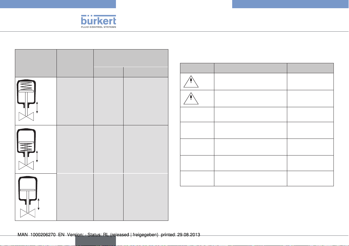
2. SYMBOLS
The following symbols are used in these instructions.
DANGER!
Warns of an immediate danger.
▶ Failure to observe the warning will result in a fatal or serious injury.
WARNING!
Warns of a potentially dangerous situation.
▶ Failure to observe the warning may result in a serious or fatal injury.
CAUTION!
Warns of a possible danger.
▶ Failure to observe this warning may result in a moderate or minor
injury.
NOTE!
Warns of damage to property.
Important tips and recommendations.
Refers to information in these operating instructions or in
other documentation.
▶ Indicates an instruction to prevent risks.
→ designates a procedure which you must carry out.
english
5
Page 6
Typ 8750
Authorized use
3. AUTHORIZED USE
Non-authorized use of the flow controller Type 8750 may be a
hazard to people, nearby equipment and the environment.
• The device is designed as a simple system for determining and
controlling the volumetric flow rate of gases.
• Do not expose the device to direct sunlight.
• Do not use the device outdoors.
• Use according to the authorized data, operating conditions, and
conditions of use specified in the contract documents and operating instructions. These are described in Chapter “7. Technical
data”.
• Use the device only in conjunction with third-party devices and
components recommended and authorized by Bürkert.
• Correct transportation, storage, and installation, as well as careful use and maintenance are essential for reliable and faultless
operation.
• Use the device only as intended.
3.1. Restrictions
If exporting the system/device, observe any existing restrictions.
4. BASIC SAFETY INSTRUCTIONS
These safety instructions do not make allowance for any
• Contingencies and events which may arise during the installation,
operation, and maintenance of the devices.
• Local safety regulations – the operator is responsible for observing
these regulations, also in relation to the installation personnel.
Risk of injury from high pressure in the equipment/device.
▶ Before working on equipment or device, switch off the pressure
and deaerate/drain lines.
Risk of electric shock.
▶ Before reaching into the device, switch off the power supply and
secure to prevent reactivation.
▶ Observe applicable accident prevention and safety regulations
for electrical equipment.
Risk of burns/risk of fire if used during long-term operation
through hot device surface.
▶ Keep the device away from highly flammable substances and media
and do not touch with bare hands.
General hazardous situations.
▶ Devices without a separate Ex type label may not be used in a
potentially explosive area.
▶ Only trained technicians may perform installation and maintenance
work.
6
english
Page 7

Typ 8750
General information
▶ That the system cannot be activated unintentionally.
▶ After an interruption in the power supply or pneumatic supply,
ensure that the process is restarted in a defined or controlled
manner.
▶ The device may be operated only when in perfect condition and
in consideration of the operating instructions.
▶ The general rules of technology apply to application planning and
operation of the device.
▶ Do not supply the pilot air port with aggressive or flammable media.
▶ Do not supply the pilot air port with liquids.
▶ Do not physically stress the body (e.g. by placing objects on it or
standing on it).
▶ Do not make any internal or external changes on the device.
NOTE!
Electrostatic sensitive components/modules.
The device contains electronic components which react sensitively
to electrostatic discharge (ESD). Contact with electrostatically
charged persons or objects are hazardous to these components.
In the worst case scenario, they will be destroyed immediately or
will fail after start-up.
▶ Observe the requirements specified in EN 61340-5-1 to minimize/
avoid the possibility of damage caused by a sudden electrostatic
discharge.
▶ Do not touch electronic components while the supply voltage is
switched on.
5. GENERAL INFORMATION
5.1. Contact address
Germany
Bürkert Fluid Control Systems
Sales Center
Christian-Bürkert-Str. 13-17
D-74653 Ingelfingen
Tel. + 49 (0) 7940 - 10 91 111
Fax + 49 (0) 7940 - 10 91 448
E-mail: info@de.buerkert.com
International
Contact addresses can be found on the final pages of the printed
operating instructions.
And also on the Internet at:
www.burkert.com
5.2. Warranty
The warranty is only valid if the flow controller Type 8750 is used as
intended in accordance with the specified application conditions.
5.3. Information on the Internet
The operating instructions and data sheets for Type 8750 / Type 8693
can be found on the Internet at:
www.burkert.com
english
7
Page 8

Typ 8750
System description
6. SYSTEM DESCRIPTION
6.1. General description
To determine and control the volumetric flow rate, the pressure drop
over the control valve is measured continuously by the two pressure
sensors. This pressure difference and the valve flow characteristic
are the parameters used to determine the volumetric flow. This measured volumetric flow is compared with the set point – internally via
display/keyboard or externally via standard signal or bus protocol –
evaluated in a PID controller and set on the position controller as the
new set point.
The system consists of:
• Control valve Type 2712 with process controller Type 8693
• Two pressure sensors Type 8323
Options:
• Binary input
• Analog feedback
• 2 binary outputs
• Bus communication (PROFIBUS DP or DeviceNet)
Other:
• The flow controller is supplied with a factory setting.
• The device is operated via 4 function keys and a display.
• The valve seat can be exchanged.
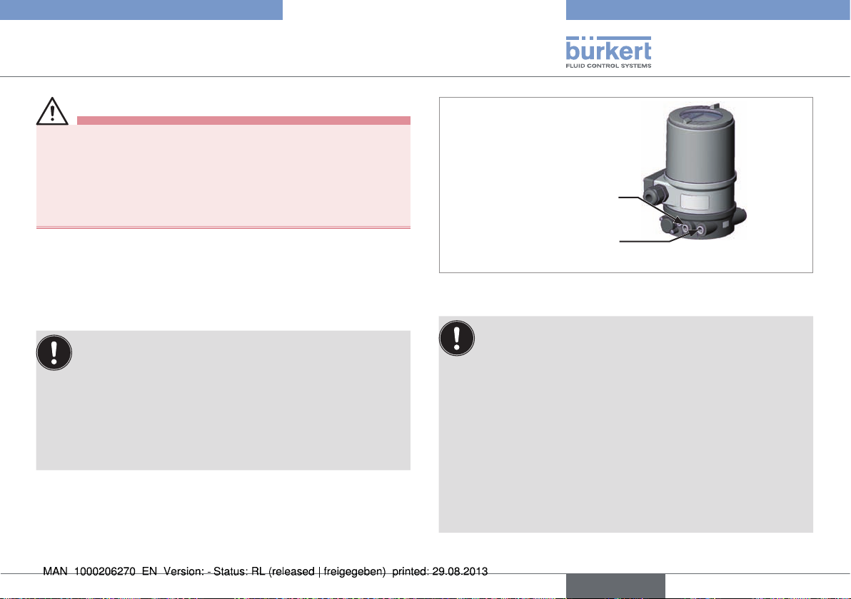
6.2. Structure
Process controller Type 8693
Actuator control valve Type 2712
Signal line from pressure sensor to
the process controller
Valve body control valve
Type 2712
Pressure sensor Type 8323
Fig. 1: Structure
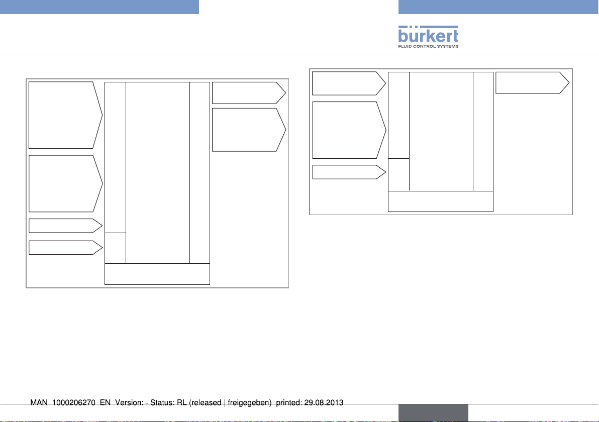
6.2.1. Action diagram of the FMR
Pressure P1 Pressure P2
Temperature T
(Option)
P1 P2
Fig. 2: Action diagram
Kv value
PV
Flow
controller
(FMR)
Type
8750
Flange acc. to
DIN EN 1092-1
8
english
Page 9
Typ 8750
System description
6.2.2. Electrical interfaces
Inputs for position
or process setpoint value
0 – 20 mA
4 – 20 mA
0 – 5 V
0 – 10 V
Inputs for process
actual value
(4 – 20 mA)
P1
P2
T (optional)
Binary input
24 V DC
Fig. 3: Interfaces
Inputs
Power
supply
Process controller
Type 8693
Operation
(keys)
2 binary outputs
(option)
Analog
position
feedback
(option)
Outputs
Bus
Inputs for process
actual value
(4 – 20 mA)
P1
P2
T (optional)
24 V DC
Fig. 4: Interfaces - Bus
Process controller Type
Inputs
8693
PROFIBUS DP
DeviceNet
Power
supply
Operation
Bus
Outputs
english
9
Page 10
Typ 8750
Technical data
7. TECHNICAL DATA
7.1. Conformity
Type 8750 conforms to the EC directives according to the EC Declaration of Conformity.
7.2. Standards
The applied standards which are used to demonstrate compliance with
the EC Directives are listed in the EC type test certificate and/or the
EC Declaration of Conformity.
7.3. Operating conditions
Ambient temperature 0 – +55 °C
Degree of protection
IP65 / IP67 according to EN 60529 (only if cables, plugs and
sockets have been connected correctly and in compliance with
the exhaust air concept in Chapter “9.3. Pneumatic connection
of the process controller”)
7.4. Mechanical data
Materials
Valve body stainless steel cast 1.4404/316L
Sensor connection 1.4301 or 1.4404
Flange stainless steel 316L
Actuator Polyamide (PA)
Process controller PPS, PC, stainless steel
seals EPDM
Packing gland PTFE rings with silicone grease
Other wetted parts stainless steel 1.4571
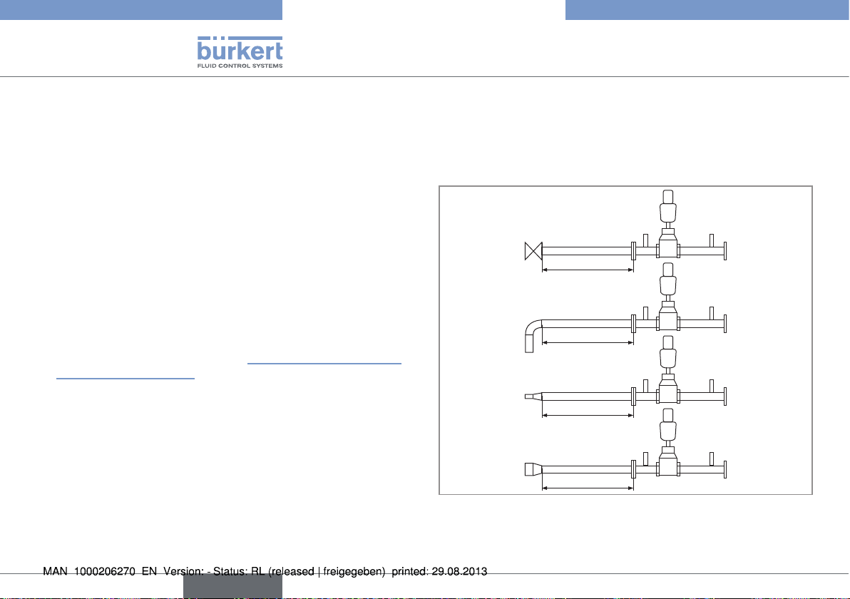
Inlet and outlet sections acc. to EN ISO 5167-1
Inlet sections
Valve completely open
20 x D
90° bend or T-piece
20 x D
Widening
18 x D
Reduction
15 x D
Fig. 5: Inlet sections
Outlet sections already integrated in the system (6 x DN)
10
english
Page 11

Typ 8750
Technical data
Dimensions
∅ 91
∅ E
HG
2x DN
L
Fig. 6: Dimensions
6x DN
DN pipe connection [mm] L [mm] HG [mm] ∅ E [mm]
15 330 414 101
25 500 412 101
40 700 501 127
50 800 538 157
65 1000 567 157
80 1200 637 261
100 1400 647 261
Tab. 1: Dimensions
7.5. Type label
Example:
Operating voltage /
Fig. 7: Example of type label
control
Type
8750 24 V DC
single act Pilot 0,6
Pmax 7 bar
Tamb 0°C - +55°C
S/N 001000
00179026
D-74653 Ingelfingen
CE
W14UN
Identification number
Control function
Pilot valve
Maximum pressure
Max. ambient
temperature
Serial number,
CE symbol
Bar code
7.6. Fluidic data
Control medium neutral gases, air
Quality classes as per DIN ISO 8573-1
Dust content Class 5: max. particle size 40 μm,
max. particle density 10 mg/m
Water content Class 3: max. pressure dew point -20 °C or
min. 10 °C below the lowest operating
temperature
Oil content Class 5: max. 25 mg/m
3
3
english
11
Page 12

Typ 8750
Technical data
Temperature range
control medium 0 – +50 °C
Pressure range
control medium 5.5 – 7 bar (DN 15 – DN 65)
5 – 6 bar (DN 80 – DN 100)
Intrinsic air consumption 0 l/min
Connections plug-in hose connector 6 mm / 1/4”
threaded connection G 1/8
Flow media air and gases
steam on request
Temperature range
Media 0 – +80 °C
Pressure range
Media 0 – 16 bar
Connections flange acc. to DIN EN 1092-1, ANSI,
JIS
Pressure measurement
range of sensor 0 – 6/10 or 16 bar
depending on the pressure range of
media others available on request
Measurement section acc. to DIN EN 60534-2-3
Orifices DN 15 - DN 100
Sensor connections threaded connection G 1/2
7.7. Electrical data
Connections
Operating voltage circular plug-in connector M12 x 1, 4-pole
External signals circular plug-in connector M12 x 1, 8-pole
circular plug-in connector M8 x 1, 8-pole
Operating voltage 24 V DC
- maximum residual ripple 10 %
Power consumption < 5 W
Set-point value default 0/4 – 20 mA or
0 – 5/10 V
field bus as option
Display multifunction display
User interface 4 function keys
12
english
Page 13

Typ 8750
Technical data
Kv value table for FMR versions (specifications for valve stroke and flow rate in %)
The measured set of values for each seat combination is stored in the FMR memory at the factory.
Flow rate Kv in [%]
Valve design
DN
DN
pipe
seat
[mm]
[mm]
8 2,1 0,0 3,3 3,8 4,8 5,2 5,7 6,2 7,6 9,0 11,0 12,9 16,2 20,5 24,8 30,0 37,6 45,2 58,1 76,2 90,5 100,0
15
10 3,1 0,0 2,9 3,5 4,2 4,8 5,5 6,1 7,7 10,0 12,6 15,8 19,7 24,2 29,7 35,5 44,2 54,8 67,7 80,6 92,6 100,0
15 4,3 0,0 3,3 4,0 4,4 5,1 6,5 8,1 9,8 12,1 15,1 18,6 22,8 27,9 34,4 41,9 51,2 62,8 74,4 86,0 94,4 100,0
15 5,3 0,0 2,6 3,2 3,6 4,2 5,1 6,6 8,1 9,8 12,1 15,1 18,5 22,6 27,5 34,0 43,0 54,7 66,0 77,4 88,7 100,0
25
20 7,2 0,0 2,8 3,5 3,9 4,3 5,3 6,5 7,9 9,7 12,2 15,3 18,5 22,2 27,5 34,7 42,8 52,8 63,9 75,0 87,5 100,0
25 12,0 0,0 2,9 3,2 3,9 5,4 6,8 8,3 10,2 12,5 15,0 18,3 22,7 28,3 35,3 42,5 49,6 58,3 67,9 78,3 89,2 100,0
25 13,6 0,0 2,9 3,7 4,5 5,5 6,6 8,1 10,1 12,5 15,4 19,1 23,0 27,9 34,1 41,2 49,6 58,8 68,4 78,7 89,0 100,0
40
32 20,2 0,0 2,4 3,0 3,5 4,2 5,1 6,4 8,2 10,4 12,9 15,8 19,0 22,8 27,8 34,2 43,3 54,5 64,4 74,3 85,6 100,0
40 23,8 0,0 2,5 2,9 3,7 4,6 5,7 7,1 9,0 11,3 13,7 16,8 20,8 25,2 31,5 38,7 47,5 58,0 67,2 76,5 87,0 100,0
32 21,0 0,0 2,3 2,9 3,5 4,3 5,1 6,2 7,9 10,0 12,5 15,2 18,3 21,9 26,7 32,9 43,0 55,2 65,5 76,2 87,4 100,0
50
40 24,6 0,0 2,4 2,8 3,3 4,1 5,4 6,9 8,5 10,6 13,1 16,3 19,8 24,0 29,8 37,4 47,2 56,9 66,3 76,8 87,8 100,0
50 37,0 0,0 2,4 3,0 3,9 5,1 6,4 7,8 9,8 12,2 15,0 18,4 22,7 28,4 34,9 41,9 50,7 59,5 68,9 79,2 89,2 100,0
40 17,5 0,0 2,6 3,7 4,6 5,4 6,3 7,4 8,9 10,9 13,2 16,0 19,2 22,9 26,9 31,4 37,3 44,6 53,9 66,9 82,3 100,0
65
50 26,0 0,0 2,7 3,8 5,0 6,2 7,6 9,2 11,2 13,5 15,9 18,8 22,5 26,5 31,8 37,7 45,2 54,2 64,5 76,5 88,5 100,0
65 52,0 0,0 1,5 2,5 3,3 4,0 4,9 6,2 8,0 10,6 13,5 17,5 22,3 28,3 37,1 47,1 60,6 72,3 80,6 87,7 93,8 100,0
50 42,0 0,0 2,0 2,4 2,9 3,6 4,5 5,5 6,8 8,3 10,0 11,9 14,3 16,9 20,5 25,0
80
65 70,0 0,0 2,0 2,4 2,9 3,6 4,4 5,4 6,7 8,1 9,7 11,7 14,2 17,4 22,0 27,9 36,1 46,4 58,0 71,4 85,7 100,0
80 100,0 0,0 2,1 2,6 3,2 4,2 5,5 7,0 8,6 10,5 12,9 16,0 20,0 25,0 31,9 40,0 49,5 60,0 71,0 83,0 92,4 100,0
100
Tab. 2:
65 75,0 0,0 1,9 2,3 2,8 3,5 4,2 5,1 6,2 7,6 9,1 11,1 13,7 16,8 21,2 26,7 33,6 42,7 54,0 68,0 83,3 100,0
80 115,0 0,0 1,8 2,3 2,9 3,7 4,8 6,1 7,6 9,6 12,0 14,8 18,3 23,0 30,0 38,3 47,4 56,5 66,3 77,4 88,5 100,0
100 140,0 0,0 2,3 2,8 3,3 4,1 5,1 6,4 7,9 9,6 11,8 14,6 18,4 22,9 29,1 36,4 46,1 59,3 72,5 84,3 93,3 100,0
Flow rate Kv
Kvs
[m³/h]
0 5 10 15 20 25 30 35 40 45 50 55 60 65 70 75 80 85 90 95 100
Valve stroke POS [%]
30,7 38,1 46,8 59,5 76,4 100,0
english
13
Page 14

Typ 8750
Control and display elements
8. CONTROL AND DISPLAY ELEMENTS
Designation:
Function of
the keys
left
POS
POS
XXX
%
MENU INPUT CMD MANU
MENU OPN CLS AUTO
selection key
Arrow key
up arrow
Fig. 8: Description of control elements
Short description
of the value
Display for operating state AUTOMATIC:
Bar running from left to right
Unit or per-
centage of the
POS
value
Save symbol
MENU CMD POS MANU
Display for position
control
Fig. 9: Description of display
0.0
0.0
Function of the keys
Display
right
selection key
Arrow key
down arrow
Value
Symbols
1)
Bar graph
display of the
value
8.1. Function of the keys
The functions of the 4 keys differ depending on the operating state
(AUTOMATIC or MANUAL) and operating level (process level or
setting level).
The function of the keys is displayed in the gray text field which is
above the key.
Function of the keys on the process level:
Key
Arrow key
Arrow key
Selection
key
Selection
key
Function of
the keys
MENU
OPN
(OPEN)
MENU
CLS
(CLOSE)
MENU
MENU
MENU
AUTO
MENU
MANU
Description of the
function
Manual opening of the
actuator
Change the displayed value
(z.B. POS-CMD-TEMP-...)
Manual closing of the actuator
Change the displayed value
(e.g. POS-CMD-TEMP-...)
Change to the setting level
Note: Press key for approx.
3 s.
Return to AUTOMATIC operating state
Change to MANUAL operating
state
Operating
state
MANUAL
AUTOMATIC
MANUAL
AUTOMATIC
AUTOMATIC
or MANUAL
MANUAL
AUTOMATIC
1) Symbols are displayed according to the activated functions
14
english
Page 15
Typ 8750
Control and display elements
Function of the keys on the setting level:
Key
Arrow key Scroll up in the menus
Arrow key
Selection
key
Selection
key
Tab. 3: Function of the keys
Function of the
keys
MENU
+
MENU
–
←
MENU
MENU
EXIT
(BACK)
MENU
ESC
MENU
STOP
MENU
ENTER
MENU
SELEC
MENU
OK
MENU
INPUT
MENU
EXIT
(BACK)
MENU
RUN
MENU
STOP
Description of the function
Increase numerical values
Scroll down in the menus
Decrease numerical values
Change by one digit to the left; when
entering numerical values
Return to the process level
Gradually return from a sub-menu
option
Leave a menu
Stop a sequence
Select, activate or deactivate a menu
option
Gradually return from a sub-menu
option
Start a sequence
Stop a sequence
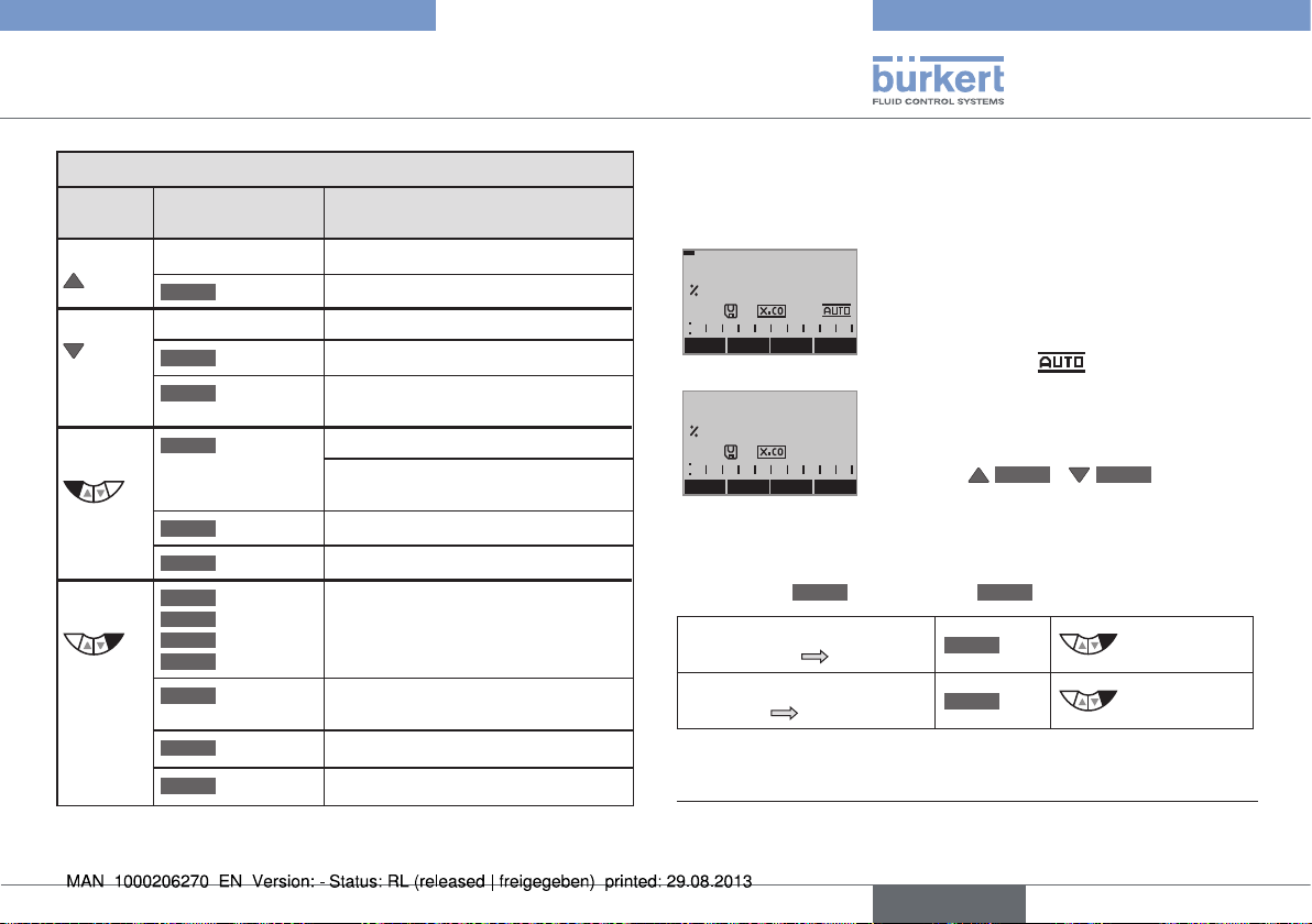
8.2. Operating state
The process controller has 2 operating states:
AUTOMATIC and MANUAL
POS
MENU CMD POS MANU
POS
MENU OPN CLS AUTO
0.0
0.0
8.2.1. Changing the operating state
Use the right selection key to switch between the two operating states
MENU
AUTOMATIC
AUTO
Switching from
AUTOMATIC MANUAL
Switching from
MANUAL
Tab. 4: Changing the operating state
2) Only possible if POS, CMD, PV (,SP) is displayed.
AUTOMATIC
AUTOMATIC
In the AUTOMATIC operating state, normal
controller mode is implemented.
(Bar running along the upper edge of the
display and symbol
displayed).
MANUAL
In the MANUAL operating state, the valve
can be opened and closed manually via the
arrow keys
and MANUAL
MENU
MANU
MENU
AUTO
MENU
OPN
MENU
MANU
2)
.
/
MENU
CLS
press
press
.
english
15
Page 16
Typ 8750
Control and display elements
8.3. Operating levels
The process controller has 2 operating levels:
• Process level
Display and operation of the current process
Operating state: AUTOMATIC / MANUAL
• Setting level
Inputting the operating parameters
Supplementing the menu by optional menu options
8.3.1. Switching between the operating levels
Switching from
process level setting level
Switching from
setting level process level
Tab. 5: Changing the operating level
If the device is in the AUTOMATIC operating state when
changing to the setting level, the process continues running
during the setting.
POS
0.0
MENU CMD POS MANU
approx. 3 s
Fig. 10: Operating levels
3)
MENU
MENU
Process level
MENU
MENU
MENU
EXIT
Setting level
press for 3 s
press
MENU
EXIT
M A I N
POS
X.TUNE
ADD.FUNCTION
EXIT ENTER
2
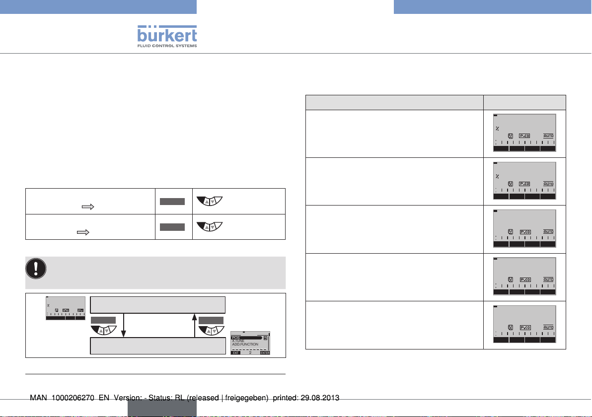
8.4. Display in AUTOMATIC operating
state
Description of the display Display
Set-point position of the valve actuator
(0 – 100 %)
Nominal position of the valve actuator
(0 – 100 %)
3)
Internal temperature in the body of the device
( °C)
Process actual value
Process set-point value
POS
MENU SP/PV CMD MANU
CMD
MENU POS TEMP MANU
TEMP
C
MENU CMD PV
PV
m3/min
MENU TEMP SP MANU
SP
m3/min
MENU PV PV
0.0
0.0
0.0
0.0
0.0
(t)
INPUT
3) During these 3 s (countdown), 2 bars converge.
16
english
Page 17

Typ 8750
Control and display elements
Description of the display Display
Simultaneous display of the nominal position
and the set-point position of the valve
actuator (0 – 100 %)
Graphical display of SP and PV with time
axis
Graphical display of POS and CMD with
time axis
Value overview
Pressure sensor P1 and P2
Time, weekday and date
Automatic adjustment of the position
controller
SP
m3/min
PV
m3/min
CMD/POS
MENU
MENU HOLD
CMD / POS (t)
MENU HOLD
P1 bar
P2 bar
MENU P.LIN SP/PV MANU
12:00
Thu. 01 . 09 . 11
POS
MENU
SP / PV (t)
CLOCK
(t)
X.TUNE
0.0
0.0
POS MANU
0.0
0.0
00
INPUT
X.TUNE
CLOCK
MENU
P.TUNE RUN
Description of the display Display
Automatic optimization of the process controller parameters
Automatic linearization of the process
characteristics
Simultaneous display of the nominal position
and the set-point position of the valve
actuator
(0 – 100 %)
Tab. 6: Display in the AUTOMATIC operating state
P.TUNE
X.TUNE
MENU
P.LIN RUN
P.LIN
CMD/POS
P.TUNE
MENU
CMD
POS
MENU P.LIN SP/PV MANU
RUN
0.0
0.0
8.5. Master code
Operation of the device can be locked via a freely selectable user
code. In addition, there is a non-changeable master code with which
you can perform all operator control actions on the device. This
4-digit master code can be found on the last pages of this quickstart
guide in the Chapter “Master code”.
If required, cut out the code and keep it separate from this quickstart
guide.
english
17
Page 18
Typ 8750
Assembly
9. ASSEMBLY
9.1. Safety instructions
DANGER!
Risk of injury from high pressure in the equipment/device.
▶ Before working on equipment or device, switch off the pressure
and deaerate/drain lines.
Risk of electric shock.
▶ Before reaching into the device, switch off the power supply and
secure to prevent reactivation.
▶ Observe applicable accident prevention and safety regulations for
electrical equipment.
WARNING!
Risk of injury from improper assembly.
▶ Installation must only be carried out by authorized technicians and
with the appropriate tools.
Risk of injury from unintentional activation of the system and
uncontrolled restart.
▶ Secure system against unintentional activation.
▶ Following assembly, ensure a controlled restart.
9.2. Before installation
The FMR can be installed in any position, preferably with the
process controller face up.
• To avoid turbulent flows around the pressure sensor, fit an
inlet section upstream of the FMR (dimensions acc. to EN
ISO 5167-1, see “Fig. 5: Inlet sections”, page 10)
• Ensure that the pipelines are correctly lined and are not
twisted. If necessary, pipelines must be suitably attached or
supported.
• Observe flow direction (arrow on valve body).
9.2.1. Installation
→ Clean pipelines and joints (sealing material, swarf, etc.).
→ Connect FMR to pipeline.
9.3. Pneumatic connection of the
process controller
DANGER!
Risk of injury from high pressure in the equipment/device.
▶ Before working on equipment or device, switch off the pressure
and deaerate/drain lines.
18
english
Page 19
Typ 8750
Assembly
WARNING!
Risk of injury from unsuitable connection hoses.
Hoses which cannot withstand the pressure and temperature
range may result in hazardous situations.
▶ Use only hoses which are authorized for the indicated pressure
and temperature range.
▶ Observe the data sheet specifications from the hose manufacturers.
Exhaust air port
label: 3
Procedure:
→ Connect the control medium to the pilot air port (1)
(3 – 7 bar; instrument air, free of oil, water and dust).
→ Fit the exhaust air line or a silencer to the exhaust air port (3).
Important information for the problem-free functioning of the
device:
• The installation must not cause back pressure to build up.
• To make the connection, select a hose with sufficient cross
section.
• The exhaust air line must be designed in such a way that
no water or other liquid can get into the device through the
exhaust air port (3).
Pilot air port
label: 1
Fig. 11: Pneumatic connection
Caution (exhaust air concept):
In compliance with protection class IP67, an exhaust air line
must be installed in the dry area.
The applied pilot pressure must always be maintained at
least 0.5 – 1 bar above the pressure which is required
to move the pneumatic actuator to its end position. This
ensures that the control behavior is not extremely negatively
affected in the upper stroke range on account of too little
pressure difference.
During operation, keep the fluctuations of the pilot pressure
as low as possible (max. ±10 %). If fluctuations are greater,
the control parameters measured with the X.TUNE function
are not optimum.
english
19
Page 20
Typ 8750
Electrical installation
10. ELECTRICAL INSTALLATION
DANGER!
Risk of electric shock.
▶ Before reaching into the device, switch off the power supply and
secure to prevent reactivation.
▶ Observe applicable accident prevention and safety regulations
for electrical equipment.
WARNING!
Risk of injury from improper installation.
▶ Installation must only be carried out by authorized technicians and
with the appropriate tools!
Risk of injury from unintentional activation of the system and
uncontrolled restart.
▶ Secure system against unintentional activation.
▶ Following assembly, ensure a controlled restart.
10.1. Electrical installation, 24 V DC with
circular plug-in connector (multi-pole
variant)
Signal values
Operating voltage 24 V DC
Set-point value (process controller) 0 – 20 mA; 4 – 20 mA
0 – 5 V; 0 – 10 V
Actual value 4 – 20 mA
Procedure:
→ Connect the process controller according to the following tables.
When the operating voltage is applied, the process controller is
operating.
→ Now enter the required basic settings and actuate automatic
adjustment of the process controller, as described in Chapter
“11. Start-up 24 V DC”, page 25.
20
english
Page 21

Typ 8750
Electrical installation
3
2
Circular plug M12, 8-pole
4
5
6
3
Input signals from the control
1
center
8
Output signals from the control
7
center (optional)
Circular plug M8, 4-pole
1
Pressure sensor P1, P2
24
2
Circular plug M12, 4-pole
3
1
Operating voltage
4
Fig. 12: Connection with 24 V DC circular plug-in connector
4) The indicated colors refer to the connecting cable available as an
accessory (919061).
5) The indicated colors refer to the connecting cable available as an
accessory (92903474).
6) The indicated colors refer to the connecting cable available as an
accessory (918038).
Circular plug M12, 8-pole
Set-point value, binary input
Pin Wire color
4)
Assignment
8 red Set-point value + (0/4 – 20 mA / 0 – 5/10 V)
7 blue Set-point value GND
1 white Binary input +
Input/output signals - option only
4)
Pin Wire color
Assignment
6 pink Analog position feedback +
5 gray Analog position feedback GND
4 yellow Binary output 1
3 green Binary output 2
2 brown Binary outputs GND
Tab. 7: Circular plug M12, 8-pole
Circular plug M8, 4-pole (pressure sensor)
Pin Wire color5)Assignment
1 brown + 24 V pressure sensor power supply
2 white 4 – 20 mA output from pressure sensor
Tab. 8: Circular plug M8, 4-pole (pressure sensor)
Circular plug M12, 4-pole (operating voltage)
Pin Wire color6)Assignment
1 brown Operating voltage + 24 V DC
3 blue Operating voltage GND
Tab. 9: Circular plug M12, 4-pole (operating voltage)
english
21
Page 22

Typ 8750
Electrical installation
10.2. Electrical installation PROFIBUS DP
Procedure:
→ Connect the process controller according to the following tables.
The electrical connection module of Type 8693 features a setscrew
with nut which is used to connect the Technical Earth (TE)
(see “Fig. 13: Connection with PROFIBUS DP”).
→ Connect setscrew (TE connection) to a suitable grounding point.
To ensure electromagnetic compatibility (EMC), ensure that the
cable is as short as possible (max. 30 cm, Ø 1.5 mm2).
When the operating voltage is applied, the process controller is
operating.
→ Now make the required basic settings and actuate automatic
adjustment of the process controller, as described in
Chapter “13. PROFIBUS DP start-up”, page 35.
The settings in the BUS.COMM menu option are described
in Chapter “13. PROFIBUS DP start-up”.
1
4
3
3
Socket M12, 5-pole
5
(inversely coded)
2
(PROFIBUS DP)
Circular plug M8, 4-pole
1
Pressure sensor P1, P2
24
2
Circular plug M12, 4-pole
3
1
Operating voltage
4
TE terminal
Fig. 13: Connection with PROFIBUS DP
Socket M12, 5-pole (bus connection)
Pin Signal
1 VP+5
2 RxD/TxD-N
3 DGND
4 RxD/TxD-N
5 Shielding
Tab. 10: Socket M12, 5-pole (bus connection)
22
english
Page 23

Typ 8750
Electrical installation
Circular plug M8, 4-pole (pressure sensor)
Pin Wire color7)Assignment
1 brown + 24 V pressure sensor power supply
2 white 4 – 20 mA output from pressure sensor
Tab. 11: Circular plug M8, 4-pole (pressure sensor)
Circular plug M12, 4-pole (operating voltage)
Pin Wire color8)Assignment
1 brown Operating voltage + 24 V DC
3 blue Operating voltage GND
Tab. 12: Circular plug M12, 4-pole (operating voltage)
7) The indicated colors refer to the connecting cable available as an
accessory (92903474).
8) The indicated colors refer to the connecting cable available as an
accessory (918038).
10.3. Electrical installation DeviceNet
Procedure:
→ Connect the process controller according to the following tables.
The electrical connection module of Type 8693 features a setscrew
with nut which is used to connect the Technical Earth (TE)
(see “Fig. 14: Connection with DeviceNet”).
→ Connect setscrew (TE connection) to a suitable grounding point.
To ensure electromagnetic compatibility (EMC), ensure that the
cable is as short as possible (max. 30 cm, Ø 1.5 mm2).
When the operating voltage is applied, the process controller is
operating.
→ Now make the required basic settings and actuate automatic
adjustment of the process controller, as described in
Chapter “14. DeviceNet start-up”, page 39.
The settings in the BUS.COMM menu option are described
in Chapter “14. DeviceNet start-up”.
english
23
Page 24

Typ 8750
Electrical installation
2
3
4
3
2
3
4
Fig. 14: Connection with DeviceNet
Circular plug M12, 5-pole
DeviceNet
1
5
Circular plug M8, 4-pole
1
Pressure sensor P1, P2
24
Circular plug M12, 4-pole
1
Operating voltage
TE terminal
Circular plug M12, 5-pole (bus connection)
Pin Signal
1 Shielding
2 V+
3 V4 CAN H
5 CAN L
Tab. 13: Circular plug M12, 5-pole (bus connection)
Circular plug M8, 4-pole (pressure sensor)
Pin Wire color9)Assignment
1 brown + 24 V pressure sensor power supply
2 white 4 – 20 mA output from pressure sensor
Tab. 14: Circular plug M8, 4-pole (pressure sensor)
Circular plug M12, 4-pole (operating voltage)
Pin Wire color
10)
Assignment
1 brown Operating voltage + 24 V DC
3 blue Operating voltage GND
Tab. 15: Circular plug M12, 4-pole (operating voltage)
9) The indicated colors refer to the connecting cable available as an
accessory (92903474).
10) The indicated colors refer to the connecting cable available as an
accessory (918038).
24
english
Page 25

Typ 8750
Start-up 24 V DC
11. START-UP 24 V DC
WARNING!
Risk of injury from improper operation.
Improper operation may result in injuries as well as damage to the
device and the area around it.
▶ Before start-up, ensure that the operating personnel are familiar
with and completely understand the contents of the operating
instructions.
▶ Observe the safety instructions and intended use.
▶ Only adequately trained personnel may operate the system/the
device.
A detailed description of the start-up and operating procedures
for Type 8693 can be found in the operating instructions for
Type 8693.
To set up the flow controller, perform the following steps:
• Specify the standard settings of the process controller (input signal
(standard signal)).
• Perform the automatic adjustment (X.TUNE) of the process controller.
• Add the F.CONTROL auxiliary function to the main menu using the
configuration menu (ADDFUNCTION) and create settings.
11.1. General procedure for creating
settings for the flow controller
Key Action Description
MENU
MENU
Press for 3 s
(countdown in the
Switching from
process level
setting level
display)
→ Execute settings.
MENU
EXIT
Press
Tab. 16: General procedure for creating settings
You must exit the main menu by pressing the left selection
MENU
EXIT
key
before the modified data is saved to the
memory (EEPROM). During the save process, the save symbol
is indicated
on the display.
Switching from
setting level
process level
english
25
Page 26

Typ 8750
Start-up 24 V DC
11.2. Define basic settings
Setting the input signal
Procedure:
Key Action Description
MENU
MENU
Press for 3 s
(countdown in the
display)
/ Select INPUT Selection INPUT menu
MENU
ENTER
Press
Select 4 - 20 mA, 0 - 20
/
mA, 0 – 10 V or 0 – 5 V
MENU
SELEC
MENU
MENU
Tab. 17: Setting the input signal
EXIT
EXIT
Press
Press
Press
Switching from
process level
Change to INPUT menu
Select the input signal
Specifying the input signal
Exit INPUT menu
Switching from
setting level
setting level
process level
MENU
ENTER
INPUT
4-20 mA
0-20 mA
0-10 V
MENU
EXIT
Fig. 15: Operating structure INPUT (select input signal)
0- 5 V
You must exit the main menu by pressing the left selection
MENU
EXIT
key
before the modified data is saved to the
memory (EEPROM). During the save process, the save symbol
is indicated
on the display.
MENU
SELEC
26
english
Page 27

Typ 8750
Start-up 24 V DC
11.3. Automatic adjustment (X.TUNE)
WARNING!
Danger of injury due to the valve position changing when the
X.TUNE function is run at operating pressure.
▶ Never run X.TUNE while the process is running.
▶ Secure system against unintentional activation.
NOTE!
An incorrect control pressure or incorrectly connected operating pressure at the valve seat may cause the controller to
be wrongly adjusted.
• X.TUNE must always be run at the control pressure available
during subsequent operation (= pneumatic auxiliary energy).
• Run the X.TUNE function preferably without operating medium
pressure to exclude interference caused by flow forces.
The following functions are actuated automatically:
• Adjustment of the sensor signal to the (physical) stroke of the
actuating element used.
• Determination of parameters of the PWM signals to control the
control valves integrated in Type 8693.
• Setting the controller parameters of the process controller. Optimization occurs according to the criteria of the shortest possible
correction time with simultaneous freedom from overshoot.
Procedure:
Taste Action Description
MENU
MENU
Press for 3 s
(countdown in the
Switching from
process level
setting level
display)
/ Select X.TUNE Selection X.TUNE menu
MENU
RUN
Press
(countdown in the
for 5 s
Start of the automatic adjustment
X.TUNE
display)
Messages on the progress of the
X.TUNE on the display:
„TUNE #1....“-„X.TUNE READY“
MENU
EXIT
Press any key Exit X.TUNE menu
MENU
EXIT
Press
Tab. 18: Setting the input signal
Switching from
setting level
process level
You must exit the main menu by pressing the left selection
MENU
EXIT
key
before the modified data is saved to the
memory (EEPROM). During the save process, the save symbol
is indicated
on the display.
11)
To stop X.TUNE, press the left or right selection key
STOP
11) „TUNE err/break“ if a fault occurs.
english
27
Page 28

Typ 8750
Start-up 24 V DC
11.4. Configuring the F.CONTROL auxiliary
function
→ Add the auxiliary function F.CONTROL to the main menu using
the configuration menu (ADDFUNCTION).
Procedure:
Key Action
MENU
MENU
Press for approx. 3 s
/ Select ADD.FUNCTION
MENU
ENTER
Press
/ Select F.CONTROL
MENU
ENTER
MENU
EXIT
Press
Press
The F.CONTROL function is now activated and incorporated into
the main menu (MAIN).
Tab. 19: Incorporating F.CONTROL into the main menu (MAIN)
→ Enter the basic settings for the flow controller under F.CONTROL.
F.CONTROL
Fig. 16: Operating structure - basic settings for flow controller
12) The SP SCALE function is indicated only if the external set-
ENTER ENTER
EXIT
PID.PARAM
F.PARAM
SETUP
EXIT
ENTER
EXIT
ENTER
EXIT
DBND 1 %
KP 1,00
TN 999,9
TV 0,0
X0 0,0 %
FILTER 0
MTMP
DENS
MTMP.INPUT
DIAMETER
PV-INPUT
PV-SCALE
SP-INPUT
SP-SCALE
P.CO INIT
VALVE
point value default (external) menu option is activated under SP
INPUT.
12)
28
english
Page 29

Typ 8750
Start-up 24 V DC
F.CONTROL - Settings:
PID.PARAM
DBND 0,1 %
KP 0,00
TN 0,5
TV 0,0
X0 0,0 %
FILTER 0
F.PARAM
MTMP
DENS
SETUP
MTMP.INPUT
DIAMETER
PV-INPUT
Parameter settings for the PID process
controller
Insensitivity area (dead band) of the PID
process controller
Amplification factor of the process controller
Reset time
Hold-back time
Working point
Filtering of the process actual value input
Parameter settings for the flow controller
Manually specifying the medium temperature
MTMP.INPUT: In this case, manual refers to:
Density: Enter the density of the medium
Setting up the flow controller
Specify the medium temperature: can be set
either via temperature transmitter or via bus
Enter the pipe diameter
Indication of the signal type for process actual
value
PV-SCALE
SP-INPUT
SP-SCALE
P.CO-INIT
VALVE
Tab. 20: Basic settings for the flow controller
Scaling the process controller
(m/s or m³/h only)
Type of the set-point value default
(internal or external)
Scaling the position controller
13)
(for external set-point value default only)
Enables a smooth switchover between
AUTOMATIC and MANUAL operating state
Save a valve-specific Kv characteristic and the
Kvs value, customer settings also possible
The parameter settings for the PID process controller can be
created automatically with the help of the P.TUNE function
(description see “operating instructions for Type 8693”).
13) The SP SCALE function is indicated only if the external set-point
value default (external) menu option is activated under SP INPUT
english
29
Page 30

Typ 8750
Additional FMR functions
11.4.1. Change the process set-point value
Procedure:
1. Set the set-point value default on the setting level:
In the main menu (MAIN), select the F.CONTROL function
F.CONTROL
→ Use the
ENTER
MENU
EXIT
SETUP
key (press 4 x) to return to the process level.
ENTER
SP-INPUT
intern
2. On the process level, manually change the process set-point
value:
→ Use the arrow keys to select the
display for the process set-point value (SP).
MENU
INPUT
→ Press
key.
SP
m3/min
MENU PV PV
30.0
(t)
→ Enter the process set-point value (see image below).
SET VALUE
SP:
[m3/min]
+ <
ESC
Fig. 17: Enter values
70.0
+
070.
-
OK
Change by one position to the left
Increase number
Return without change
Changeable number
0
Accept set value
SELEC
INPUT
12. ADDITIONAL FMR FUNCTIONS
Overview
ADD.FUNCTION
ENTER
EXIT
Fig. 18: Overview of FMR auxiliary functions
CHARACT
CUTOFF
DIR.CMD
DIR.ACT
SPLTRNG
X.LIMIT
X.TIME
X.CONTROL
F.CONTROL
SECURITY
SAFEPOS
SIG.ERROR
BINARY.IN
OUTPUT
CAL.USER
SET.FACTORY
SER. I/O
EXTRAS
SERVICE
SIMULATION
DIAGNOSE
1
2
3
4
14)
5
6
7
8
9
10
11
12
13
14
15
16
17
18
19
20
21
30
english
Page 31

Typ 8750
Additional FMR functions
No Description
1
Selecting the transfer characteristic between input signal and
stroke (correction characteristic)
2
Sealing function for position controller
3
Effective sense of direction between input signal and nominal
position
4
Assignment of the aeration state of the actuator chamber to
the set-point position
5
Signal split range
14)
; input signal as a % for which the valve
runs through the entire stroke range.
6
Limit the mechanical stroke range
7
Limit the control speed
8
Parameterization of the position controller
9
Parameterization of the PID process controller
10
Code protection for settings
11
Input the safety position
12
Configuration of signal level fault detection
13
Activation of the binary input
14
Configuration of outputs (option)
15
Calibration
16
Reset to factory settings
17
Configuration of serial interface
18
Adjusting the display
No Description
19
For internal use only
20
Simulation of set-point value, process valve, process
21
Diagnosis menu (option)
Tab. 21: Description of auxiliary functions
14) The auxiliary function SPLTRNG can only be selected if
F.CONTROL (process control) is not activated.
The auxiliary functions listed here can be activated and set in accordance with the control task.
A detailed description of the auxiliary functions and settings
can be found in the user instructions for Type 8693.
The following auxiliary functions differ from Type 8693 and are
described in these instructions:
• CAL.USER see Chapter “12.2. CAL.USER - Changing the
factory calibration”
• OUTPUT see Chapter “12.3. OUTPUT - Configuration of
the analog output”
english
31
Page 32

Typ 8750
Additional FMR functions
12.1. Activating and deactivating
auxiliary functions
You can activate the auxiliary functions on the setting level by adding
them to the main menu (MAIN). The parameters for the auxiliary
functions can then be set.
To deactivate an auxiliary function, remove it from the main menu.
The previous settings created using this auxiliary function will then
be rendered invalid again as a result.
12.1.1. Including auxiliary functions in the
main menu
Procedure:
Key Action
MENU
MENU
MENU
ENTER
MENU
ENTER
MENU
EXIT
The auxiliary function is now activated and added to the main menu
(MAIN).
Tab. 22: Adding auxiliary functions to the main menu (MAIN)
Press for approx. 3 s
/ Select ADD.FUNCTION
Press
/ Select the auxiliary function
Press
Press
You must exit the main menu by pressing the left selection
MENU
EXIT
key
before the modified data is saved to the
memory (EEPROM). During the save process, the save symbol
is indicated
on the display.
12.2. CAL.USER - Changing the factory
calibration
→ Add the CAL.USER auxiliary function to the main menu using the
configuration menu (ADDFUNCTION).
→ Enter the settings for the flow controller under CAL.USER.
32
english
Page 33

Typ 8750
Additional FMR functions
CAL.USER
ENTER
calibr. POS
ENTER
POS. pMIN
INPUT
OK
Enter value
(POS.lower:)
EXIT
POS. pMAX
INPUT
OK
Enter value
(POS.upper:)
CAL.FMR
ENTER
CAL.PLIM
CAL.P1
CAL.P2
CAL.P1‘P2
CAL.TLIM
EXIT
CAL.TEMP
Fig. 19: Operating structure CAL.USER - changing the factory calibration
- 1
calibr. SP
16)
INPUT
OK
16)
INPUT
OK
16)
INPUT
OK
16)
INPUT
OK
Create and
confirm
minimum
value
Create and
confirm
minimum
value
Create and
confirm
minimum
value
Create and
confirm
minimum
value
EXIT
Press for approx. 3 s
ENTER
EXIT
17)
calibr. PV
ENTER
EXIT
copyFACT->User
RUN
SP 4 mA 0
SP 20mA 0
PV 4 mA 0
PV 20mA 0
Reset the settings of CAL.USER to
factory settings
Fig. 20: Operating structure CAL.USER - changing the factory calibration - 2
MENU
15) If you press the key
16) The specified input signal type is displayed.
17) If the specified signal type for the process actual value is Pt 100,
ESC
the value remains unchanged.
the input screen for the temperature value appears.
english
33
Page 34

CAL.USER - Settings:
calibr. POS
POS. pMIN
POS. pMAX
Calibration of the position actual value
Set the minimum position of the valve
Set the maximum position of the valve
Typ 8750
Additional FMR functions
calibr. PV
for input signal 4 - 20 mA:
PV 4mA 0
PV 20mA 0
Calibrating the process actual value
Minimum value of the input signal
Maximum value of the input signal
CAL.FMR
CAL.PLIM
CAL.P1
CAL.P2
CAL.P1‘P2
CAL.TLIM
CAL.TEMP
calibr. SP
SP 4mA 0
SP 20mA 0
34
Calibration of the flow controller
Measurement range of the pressure sensor
Calibration of pressure sensor 1
Calibration of pressure sensor 2
P1-P2 comparison increase in accuracy
Measurement range of the temperature
transmitter
Calibrating the temperature transmitter
Calibrating the process set-point value
Minimum value of the input signal
Maximum value of the input signal
english
for input signal Pt 100:
0000
copyFACT->USER
Tab. 23: CAL.USER settings
Temperature
Reset to factory settings
12.3. OUTPUT - Configuration of the
analog output
The analog output can send feedback regarding the current position
(POS) or the set-point value (CMD), the process actual value (PV),
the process set-point value (SP), the pressure at the input (P1), the
pressure at the output (P2) or the medium temperature (MTMP) to
the control center.
→ Add the auxiliary function OUTPUT to the main menu using the
configuration menu (ADDFUNCTION).
→ Create the settings for the flow controller under OUT ANALOG.
Page 35

Typ 8750
PROFIBUS DP start-up
OUT ANALOG
ENTER
EXIT
Fig. 21: Operating structure OUT ANALOG - analog output
POS
CMD
MTMP
OUT type
PV
SP
P1
P2
ENTER
EXIT
SELEC
Output of set-point position
Output of nominal position
Output of the process actual value
Output of the process set-point value
Output of the pressure P1 (input)
Output of the pressure P2 (output)
Output of medium temperature
SELEC
4 - 20 mA
0 - 20 mA
0 - 10 V
0 - 5 V
Selection
of the
standard
signal
13. PROFIBUS DP START-UP
Procedure:
• Perform the automatic adjustment (X.TUNE) of the process controller.
• Add the F.CONTROL auxiliary function to the main menu using the
configuration menu (ADDFUNCTION) and make settings.
• Make settings in the BUS.COMM function.
• Configuration of the process values.
13.1. Settings in BUS .COMM
Address 0
BUS FAIL
SafePos off
SafePos on
SAFEPOS activated:
The actuator moves to the safety position which is specified in the
SAFEPOS auxiliary function.
SAFEPOS deactivated:
The actuator moves to the safety end position which it would
assume if the electrical and pneumatic auxiliary energy failed.
See Chapter “15. Safety end positions”.
Enter a device address (value between 0 and 126)
Activate or deactivate approach of the safety
position
The actuator remains in the position which corresponds to the set-point value last transferred
(default setting).
If there is a fault in the bus communication, the
behavior of the actuator depends on the activation of the SAFEPOS auxiliary function.
english
35
Page 36

BUS.COMM
Typ 8750
PROFIBUS DP start-up
ENTER
Address 0
INPUT
+
–
18)
OK
BUS FAIL
ENTER
EXIT
BUS PDI
ENTER
EXIT
Fig. 22: Operating structure BUS.COMM - 1
Enter
value
Input device
address.
Adjustment
range: 0 – 126
SELEC
SafePos off
SafePos on
POS
CMD
Temperature
Operation mode
Errors
P1
P2
Mtmp
P.CONTROL active
Start up of
the safety
position
SELEC
Process
values
which are
transferred
to the
controller
EXIT
BUS PDO
ENTER
EXIT
CMD
Operation mode
Error reset
Mtmp
P.CONTROL active
SELEC
Process
values
which are
transferred
from the
controller
Fig. 23: Operating structure BUS.COMM - 2
MENU
18) If you press the key
ESC
, the value remains unchanged.
13.2. Configuration of the process
values
The following components are required for the configuration:
• Software suitable for the configuration. For example Step7 from
Siemens.
• GSD file (Download from the Bürkert homepage)
For more detailed information see supplementary instructions on the
Bürkert homepage:
• “Configuration on the PROFIBUS by means of GSD file”
www.burkert.com → Type 8793 → Config. PROFIBUS by GSD file
→ First input the PDI (Process Data Input).
36
english
Page 37

Typ 8750
PROFIBUS DP start-up
PDI: Process Data Input (from the process controller to the controller)
Name Description Identifier
PDI:POS
PDI:CMD
PDI:PV
PDI:SP
Actual position (position)
Actual value of positioner as ‰.
Value range 0 – 1000.
Values < 0 or > 1000 are
possible if e.g. X.TUNE has not
run through correctly.
Set-point position (command)
Set-point value of positioner
as ‰.
Value range 0 – 1000.
Process actual value
(process value)
Actual value of process controller
in physical unit (as set in the menu
P.CO INP or P.CO SCAL),
max. value range -999 – 9999,
depending on internal scaling.
Process set-point value (set-point)
Set-point value of process
controller in physical unit
(as set in the menu P.CO INP or
P.CO SCAL),
max. value range -999 – 9999,
depending on internal scaling.
GSD file:
PDI:POS
Identifier (HEX):
41, 40, 00
GSD file:
PDI:CMD
Identifier (HEX):
41, 40, 01
GSD file:
PDI:PV
Identifier (HEX):
41, 40, 02
GSD file:
PDI:SP
Identifier (HEX):
41, 40, 03
Name Description Identifier
PDI:TEMP
PDI:MODE
PDI:ERR
Device temperature (temperature)
Temperature of 0.1 °C is
measured on the CPU board by
the sensor,
value range -550 (-55 °C) –
+1250 (+125 °C).
Operating state (operation mode)
Operating state:
0: AUTO
1: MANUAL
2: XTUNE
9: P.QLIN
10: P.TUNE
12: BUSSAFEPOS
Error
Indicates the number of the
process value (output) which was
not written. The value is retained
until it is deleted with PDO:ERR.
HEX
14 PDO:CMD / SP
16 PDO:MODE
GSD file:
PDI:TEMP
Identifier (HEX):
41, 40, 04
GSD file:
PDI:MODE
Identifier (HEX):
41, 00, 05
GSD file:
PDI: ERR
Identifier (HEX):
41, 00, 06
english
37
Page 38

Typ 8750
PROFIBUS DP start-up
Name Description Identifier
PDI:P1
PDI:P2
PDI:MTMP
PDI:
PCONact
Tab. 24: Process Data Input, PROFIBUS DP
Pressure before the valve
0000-XXXX depending on sensor
range
Pressure before the valve
0000-XXXX depending on sensor
range
Medium temperature
Temperature in °C on 1 °C exactly
Value range 0 °C – 150 °C
0: Positioner
1: Process controller
GSD file:
PDI:P1
Identifier (HEX):
41, 40, 07
GSD file:
PDI:P2
Identifier (HEX):
41, 40, 08
GSD file:
PDI:MTMP
Identifier (HEX):
41, 40, 09
GSD file:
PDI:PCONact
Identifier (HEX):
41, 00, 0A
→ Then input the process data output.
PDO: Process Data Output (from the controller to the process
controller)
Name Description Identifier
PDO:
CMD/SP
PDO:
MODE
Process set-point value
(set-point)
Set-point value of process controller in physical unit (as set in the
menu P.CO INP or P.CO SCAL),
max. value range -999 – 9999,
depending on internal scaling.
If the value is too small or too
large, the last valid value is used
and is indicated in ERR with HEX
14.
Operating state (operation mode)
Value range 0, 1 or 12:
Operating state:
0: AUTO
1: MANUAL
12: BUSSAFEPOS
If the value is too small or too
large, the last valid value is used
and is indicated in ERR with HEX
16.
GSD file:
PDO:CMD/SP
Identifier (HEX):
81, 40, 14
GSD file:
PDO:MODE
Identifier (HEX):
81, 00, 16
38
english
Page 39

Typ 8750
DeviceNet start-up
Name Description Identifier
PDO:ERR
PDO:
MTMP
PDO:
CONact
Tab. 25: Process Data Output, PROFIBUS DP
Reset error display
If the value > 0, ERR is reset.
Medium temperature
Temperature in °C on 1 °C exactly
Value range 0 °C – 150 °C
0: Positioner
1: Process controller
GSD file:
PDO: ERR
Identifier (HEX):
81, 00, 17
GSD file:
PDO:MTMP
Identifier (HEX):
81, 40, 18
GSD file:
PDO:CONact
Identifier (HEX):
81, 00, 19
14. DEVICENET START-UP
Procedure:
• Perform the automatic adjustment (X.TUNE) of the process controller.
• Add the F.CONTROL auxiliary function to the main menu using the
configuration menu (ADDFUNCTION) and create settings.
• Make settings in the BUS.COMM function.
• Configuration of the process values.
14.1. Settings in BUS .COMM
Address 0
BAUD RATE
• The baud rate can be changed either by pressing the operator keys
on the device or via the bus.
• A change has no effect until a reset (send a reset message to
the identity object) or power up is implemented. This means if the
changed baud rate attribute is accessed before a reset or power up,
the read (changed) value does not agree with the still current baud
rate (to be changed) of the network.
Select 125 kbit/s, 250 kbit/s or 500 kbit/s
Enter a device address (value between 0 and 63)
Selection of the baud rate
english
39
Page 40

Typ 8750
DeviceNet start-up
BUS FAIL
Activate or deactivate approach of the safety
position
SafePos off
The actuator remains in the position which corresponds to the set-point value last transferred
(default setting).
SafePos on
If there is a fault in the bus communication, the
behavior of the actuator depends on the activation of the SAFEPOS auxiliary function.
SAFEPOS activated: The actuator moves to the safety position
which is specified in the SAFEPOS auxiliary function.
SAFEPOS deactivated: The actuator moves to the safety end
position which it would assume if the electrical and pneumatic auxiliary energy failed.
See Chapter “15. Safety end positions”.
BUS.COMM
ENTER
EXIT
Fig. 24: Operating structure BUS.COMM - DeviceNet
Address 0
INPUT
OK
BAUD RATE
ENTER
EXIT
BUS FAIL
ENTER
EXIT
18)
+
–
Enter
value
125 kBd
250 kBd
500 kBd
SafePos off
SafePos on
Input device
address.
Adjustment range:
0 – 63
SELEC
Selection
of the baud
rate
SELEC
Activate /
deactivate
approach
of the
safety
position
40
english
Page 41
Typ 8750
DeviceNet start-up
14.2. Configuration of the process data
The following components are required for the configuration:
• Software suitable for the configuration. For example RSNetWorx for
DeviceNet (Rev. 4.12.00).
• ESD file (is on the supplied CD).
Transferring process data
The process data is transferred via an I/O connection. 5 static input
and 2 static output assemblies can be selected for the transfer. In these
assemblies selected attributes are combined in one object.
Selecting the process data
The process data is selected by setting the device parameters during
initialization of the I/O connection according to the DeviceNet specification. The following device parameters can be set:
• Active Input Assembly and Active Output Assembly or
• Produced Connection Path and Consumed Connection Path
- if supported by the DeviceNet Master/Scanner -.
14.2.1. Static Input Assemblies
Name Address of data
attribute of the
assemblies for
read access. Class,
instance, attributes
POS+ERR
(factory setting)
POS+CMD+ERR
PV+ERR
PV+SP+ERR
4, 1, 3 Byte 0: POS low
4, 2, 3 Byte 0: POS low
4, 3, 3 Byte 0: PV low
4, 5, 3 Byte 0: PV low
Format of the data
attribute
Byte 1: POS high
Byte 2: ERR
Byte 1: POS high
Byte 2: CMD low
Byte 3: CMD high
Byte 4: ERR
Byte 1: PV high
Byte 2: ERR
Byte 1: PV high
Byte 2: SP low
Byte 3: SP high
Byte 4: ERR
english
41
Page 42

Typ 8750
DeviceNet start-up
Name Address of data
attribute of the
assemblies for
read access. Class,
instance, attributes
PV+SP+CMD+
ERR
PV+P1+P2+
MTMP+ERR
4, 5, 3 Byte 0: PV low
4, 6, 3 Byte 0: PV low
Format of the data
attribute
Byte 1: PV high
Byte 2: SP low
Byte 3: SP high
Byte 4: CMD low
Byte 5: CMD high
Byte 6: ERR
Byte 1: PV high
Byte 2: P1 low
Byte 3: P1 high
Byte 4: P2 low
Byte 5: P2 high
Byte 6: MTMP low
Byte 7: MTMP high
Byte 8: ERR
Name Address of data
attribute of the
assemblies for
read access. Class,
instance, attributes
PV+SP+CMD+
P1+P2+
MTMP+ERR
PV+POS+ERR+
PCON
4, 7, 3 Byte 0: PV low
4, 8, 3 Byte 0: PV low
Format of the data
attribute
Byte 1: PV high
Byte 2: SP low
Byte 3: SP high
Byte 4: CMD low
Byte 5: CMD high
Byte 6: P1 low
Byte 7: P1 high
Byte 8: P2 low
Byte 9: P2 high
Byte 10: MTMP low
Byte 11: MTMP high
Byte 12: ERR
Byte 1: PV high
Byte 2: POS low
Byte 3: POS high
Byte 4: ERR
Byte 5: PCON
active
42
english
Page 43

Typ 8750
DeviceNet start-up
Name Address of data
attribute of the
assemblies for
read access. Class,
instance, attributes
PV+POS+ERR+
PCON+P1
Tab. 26: Static Input Assemblies, DeviceNet
The addresses indicated in “Tab. 26” can be used as a path
statement for the Produced Connection Path attribute of an
I/O connection.
This I/O connection can be used to transfer the attributes described
in more detail in the following “Tab. 27” as input process data.
Nevertheless, by using this address data, the attributes combined
in the assemblies can also be accessed acyclically at any time via
Explicit Messages.
4, 9, 3 Byte 0: PV low
Format of the data
attribute
Byte 1: PV high
Byte 2: POS low
Byte 3: POS high
Byte 4: ERR
Byte 5: PCON
active
Byte 6: P1 low
Byte 7: P2 low
Name Description of the input data
attributes
POS
CMD
PV
SP
Actual position
Actual value of process controller
as ‰.
Value range 0 – 1000.
However, values <0 or >1000 are
also possible if e.g. X.TUNE has not
run through correctly.
Set-point position
Set-point value of positioner as ‰.
Value range 0 – 1000.
Process actual value (process value)
Actual value of process controller
in physical unit (as set in the
menu P.CO INP or P.CO SCAL),
max. value range -999 – 9999,
depending on internal scaling.
Process set-point value
Set-point value of process con-
troller in physical unit (as set in the
menu P.CO INP or P.CO SCAL),
max. value range -999 – 9999,
depending on internal scaling.
Attribute
Address Class,
Instance,
Attribute; Data
type, Length
111, 1, 59;
INT, 2 byte
111, 1, 58;
UINT, 2 byte
120, 1, 3;
INT, 2 byte
120, 1, 2;
INT, 2 byte
english
43
Page 44

Typ 8750
DeviceNet start-up
Name Description of the input data
attributes
ERR
Error
Indicates the number of the process
value (output) which was not written.
The value is retained until it is deleted
with "1" by acyclically writing the
"Error" attribute (access via Explicit
Message – Set Attribute Single).
HEX
0X14 INP
0X15 SP
P1
P2
MTMP
PCONact
Tab. 27: Input data attributes; DeviceNet
Pressure before the valve in bar 120, 1, 7;
Pressure after the valve in bar 120, 1, 8;
Medium temperature in °C 120, 1, 9;
P.CONTROL active 120, 1, 10;
Attribute
Address Class,
Instance,
Attribute; Data
type, Length
100, 1, 1;
USINT, 1 byte
INT, 2 byte
INT, 2 byte
INT, 2 byte
USINT, 1 byte
14.2.2. Static Output Assemblies
Name Address of data
attribute of the
Format of the data
attribute
assemblies for
read access. Class,
instance, attributes
INP
(factory setting)
SP
4, 21, 3 Byte 0: INP low
Byte 1: INP high
4, 22, 3 Byte 0: SP low
Byte 1: SP high
MTMP
4, 23, 3 Byte 0: MTMP low
Byte 1: MTMP high
SP+MTMP
4, 24, 3 Byte 0: SP low
Byte 1: SP high
Byte 2: MTMP low
Byte 3: MTMP high
MTMP+SP+
ERR+PCON
4, 25, 3 Byte 0: MTMP low
Byte 1: MTMP high
Byte 2: SP low
Byte 3: SP high
Byte 4: ERR
Byte 5: PCON
active
Tab. 28: Static Output Assemblies, DeviceNet
The addresses indicated in “Tab. 28” can be used as a path
statement for the Consumed Connection Path attribute of an I/O
connection.
44
english
Page 45

Typ 8750
DeviceNet start-up
This I/O connection can be used to transfer the attributes described
in more detail in the following “Tab. 29” as output process data.
Nevertheless, by using this address data, the attributes combined
in the assemblies can also be accessed acyclically at any time via
Explicit Messages.
Name Description of the output data
attributes
INP
Set-point position
Set-point value of process con-
troller as ‰. Value range 0 – 1000.
In "pure" position controller
mode (F.CONTROL inactive)
the transfer of the INP set-point
position is required; as a process
controller (F.CONTROL active)
the transfer of INP is not possible.
If the value is too small or too large,
the last valid value is used and is
indicated in ERR with HEX 14.
Attribute
Address Class,
Instance,
Attribute; Data
type, Length
111, 1, 58;
UINT, 2 byte
Name Description of the output data
attributes
SP
MTMP
PCONact
Tab. 29: Output data attributes; DeviceNet
Process set-point value
Set-point value of process con-
troller in physical unit (as set in the
menu P.CO INP or P.CO SCAL),
max. value range -999 – 9999,
depending on internal scaling.
If the value is too small or too large,
the last valid value is used and is
indicated in ERR with HEX 15.
Medium temperature in °C 120, 1, 9;
P.CONTROL active 120, 1, 10;
Attribute
Address Class,
Instance,
Attribute; Data
type, Length
120, 1, 2;
INT, 2 byte
INT, 2 byte
USINT, 1 byte
english
45
Page 46
Typ 8750
Safety end positions
15. SAFETY END POSITIONS
Safety end positions after
Actuator
system
up
down
up
down
up
down
Designation
single-acting
Control
function A
single-acting
Control
function B
double-acting
Control
function I
failure of the auxiliary power
electrical pneumatic
down
up
down / up
(depending
on the con-
nection of
the control
cables)
pilot-controlled
control system:
down
direct-acting
control system:
not defined
pilot-controlled
control system:
up
direct-acting
control system:
not defined
not defined
16. ERROR MESSAGES
General error messages (display only for external set-point value and
with activated SIG.ERR).
Display Cause Remedial action
Minimum input value has
min
max
SP error
P1 error
P2 error
invalid code Incorrect access code.
EEPROM
fault
Tab. 31: General error messages
been reached.
Maximum input value has
been reached.
Signal error set-point value
process controller
Signal error actual value P1
Flow control system
Signal error actual value P2
Flow control system
EEPROM defective.
Do not reduce
value further.
Do not increase
value further.
Check signal
Check signal
Check signal
Enter correct
access code.
Not possible,
device defective
Tab. 30: Safety end positions
46
english
Page 47

Typ 8750
Error messages
Error messages while the X.TUNE function is running
Display Cause Remedial action
X.TUNE
ERROR 1
X.TUNE
ERROR 2
X.TUNE
ERROR 3
X.TUNE
ERROR 4
X.TUNE
ERROR 6
No compressed air
connected.
Compressed air failure while
X.TUNE is running
Actuator or control system
deaeration side leaking
Control system aeration side
leaking.
The end positions for
POS-MIN and POS-MAX are
too close together.
Connect compressed air.
Check compressed air
supply.
Not possible,
device defective.
Not possible,
device defective.
Check compressed air
supply.
To determine
POS-MIN and
X.TUNE
ERROR 7
Incorrect assignment
POS-MIN and POS-MAX.
POS-MAX, move
the actuator in
the direction
indicated on the
display.
Tab. 32: Error messages during X.TUNE
Error messages while the P.Q‘LIN / P.TUNE function is running
Display Cause Remedial action
P.Q LIN
ERROR 1
No compressed air connected.
No change to process
variable.
Connect compressed
air.
Check process and,
if required, switch on
pump or open the
shut-off valve.
Check process
sensor.
P.Q LIN
ERROR 2
Tab. 33: Error messages during P.Q‘LIN / P.TUNE
Current node of the valve
stroke was not reached, as
• compressed air supply failed
during P.Q’LIN.
• X.TUNE was not executed.
Check compressed
air supply.
Execute X.TUNE.
english
47
Page 48

Typ 8750
Error messages
16.1. Error messages on field bus
devices
Display Cause Remedial action
MFI fault Not possible,
device defective.
Tab. 34: Error messages on field bus devices
On PROFIBUS DP
Display
BUS offline
is displayed
approx. every
3 seconds
BUS no
connection
is displayed
approx. every
3 seconds
Tab. 35: Error messages PROFIBUS DP
Field bus board
defective.
Device
state
Offline. Device is not connected to the
Online, no
connection
to the master
Remedial action
bus.
• Bus connection including plug
configuration correct?
• Power supply and bus connection of the other nodes
correct?
Device is connected correctly to
the bus, the network access procedure has ended without errors,
however there is no established
connection to the master.
Not possible,
device defective.
On DeviceNet
Display Device state Remedial action
BUS offline
is displayed
approx. every
3 seconds
BUS no
connection
is displayed
approx. every
3 seconds
Offline. Device is not connected to
the bus, the network access
procedure (duplicate MAC-ID
test, duration approx. 2 s) has
still not ended or device is
only active network node
• Baud rate correctly set
across network?
• Bus connection including
plug configuration correct?
• Power supply and bus
connection of the other
nodes correct?
Online, no
connection to
the master
Device is connected correctly
to the bus, the network
access procedure has ended
without errors, however there
is no established connection
to the master.
48
english
Page 49

Typ 8750
Error messages
BUS timeout
is displayed
approx. every
3 seconds
BUS critical err
is displayed
approx. every
3 seconds
Tab. 36: Error messages DeviceNet
I/O connection
timeout.
Critical bus
error.
An I/O connection is in the
TIME OUT state.
→ New connection estab-
lishment by master;
ensure that I/O data is
transferred cyclically or, if
COS confirmed, that corresponding Acknowledge
messages are sent by the
master.
Other device with the same
address in the network or
BUS OFF due to communication problems.
→ Change address of the
device and restart device.
→ Error analysis in the
network with a bus
monitor.
16.2. Other error messages
Display Cause Remedial action
POS = 0
(bei CMD > 0 %) or
POS = 100 %,
(when CMD < 100 %).
PV = 0
(when SP > 0) or
PV = PV
(when SP > SP ).
Applies only to devices
with binary output:
Binary output does not
switch.
Tab. 37: Other error messages
Sealing function
(CUTOFF) is unintentionally activated.
Binary output:
• Current > 100 mA
• Short circuit
Deactivate sealing
function.
Check binary
output connection.
english
49
Page 50

Typ 8750
Accessories
17. ACCESSORIES
Designation Order no.
M12 connecting cable, 8-pole,
2 m assembled cable
M12 connecting cable, 4-pole,
5 m assembled cable
M8 connecting cable, 4-pole
5 m assembled cable
USB adapter for connection to a PC in conjunction with an extension cable
Communications software based on FDT/
DTM technology
Tab. 38: Accessories
919061
918038
92903475
227093
Information at
www.burkert.com
18. SHUTDOWN
18.1. Disassembly
DANGER!
Risk of injury from high pressure in the equipment/device.
▶ Before working on equipment or device, switch off the pressure
and deaerate/drain lines.
Risk of electric shock.
▶ Before reaching into the device, switch off the power supply and
secure to prevent reactivation.
▶ Observe applicable accident prevention and safety regulations for
electrical equipment.
WARNING!
Risk of injury from improper removal.
▶ Removal may be carried out by authorized technicians only and
with the appropriate tools.
→ Remove electrical connections on the process controller.
→ Release the pneumatic connection on the process controller.
→ Remove FMR from pipeline.
50
english
Page 51

Typ 8750
Operating structure
Electrical connection
Fig. 25: Disassembly of FMR
Process controller
Pneumatic connection
19. OPERATING STRUCTURE
The factory presets are highlighted in blue to the right of the menu in
the operating structure.
/ Menu options activated or selected at the factory
/ Menu options not activated or selected at the factory
2 %, 10 sec Values set at the factory
ACTUATOR
INPUT
BUS.COMM
X.TUNE BUS PDI
Fig. 26: Operating structure FMR - 1
18)
SINGLE CHARACT CHARACT
DOUBLE
4-20 mA
0-20 mA
0-10 V
0-5 V
Address X
BAUDRATE
BUSFAIL
19)
Address: 63
125 kBd
250 kBd
500 kBd
SafePos off
SafePos on
63
english
51
Page 52

Typ 8750
Operating structure
20)
BUS PDI
20)
BUS PDO
Automatic X.TUNE
X.TUNE
P.Q‘LIN
Fig. 27: Operating structure FMR - 2
19) Only for field bus
20) Only DeviceNet
21) Only PROFIBUS DP
X.TUNE started
X.TUNE.CONFIG
Position
CMD
Process value
Setpoint
Temperature
Operation mode
Errors
F.CONTRL active
Setpoint
Operation mode
Error reset
F.CONTRL active
TUNE #0 INIT X.TUNE ready
Manual X.TUNE
X.TUNE.CONFIG
X.TUNE.POS
X.TUNE.PWM
X.TUNE.AIR
P.Q‘LIN
P.TUNE
ADD.FUNCTION
Fig. 28: Operating structure FMR - 3
Q.LIN#0 CMD..
starting process..
X.TUNE.DBDx
X.TUNE.PARAx
X.TUNE.LEAKAGE
X.TUNE.Ypwm
X.TUNE.Yfric
ACT.limit
ACT.nolimit
yB.min
yE.min
time.open
time.close
Q.LIN#0 CMD.
...
POS.pMIN
POS.pMAX
TUNE.yB
TUNE.yE
Q.LIN ready
TUNE ready
52
english
Page 53
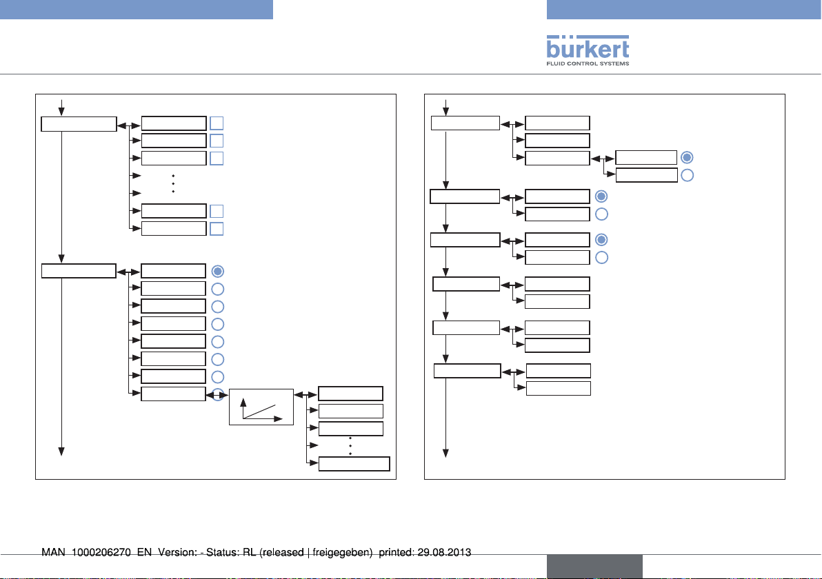
Typ 8750
Operating structure
ADD.FUNCTION
CHARACT
CUTOFF
DIR.CMD
SIMULATION
DIAGNOSE
Activatable auxiliary functions:
CHARACT linear
GP 1:25
GP 1:33
GP 1:50
GP 25:1
GP 33:1
GP 50:1
FREE
CUTOFF
Fig. 29: Operating structure FMR - 4
Activatable auxiliary
functions
Graph
GRAPH
Y0 -> 0 %
Y5 -> 5 %
Y100 -> 100 %
CUTOFF Min 0 %
Max 100 %
CUT-type
DIR.CMD Rise
Fall
DIR.ACT Rise
Fall
SPLTRNG Min 0 %
Max 100 %
X.LIMIT Min 0 %
Max 100 %
X.TIME T.open 1.0 sec
T.close 1.0 sec
X.CONTROL
Fig. 30: Operating structure FMR - 5
0 %
100 %
Type PCO
Type XCO
0 %
100 %
0 %
100 %
1.0 sec
1.0 sec
english
53
Page 54

Typ 8750
Operating structure
X.CONTROL DBND
KXopn 1
KXcls 1
KDopn 0
KDcls 0
YBfric 0
YEfric 0
F.CONTROL PID.PARAM
F.PARAM
SETUP
SECURITY
Fig. 31: Operating structure FMR - 6
DIAMETER
1.0 %
1
1
0
0
0
0
DBND 1.0 %
KP 1.00
TN 999.9
X0 0 %
FILTER 0
MTMP xxx°C
DENS x.xxx
MTMP.INPUT
TV 0.0
1.0 %
1.00
999.9 sec
0.0 sec
0 %
0
°C
MANUELL
SENSOR
BUS
SECURITY
Fig. 32: Operating structure FMR - 7
PV-SCALE
DIAMETER
PV-INPUT
?
4-20 mA
Frequenz
PT 100
54
english
Page 55

Typ 8750
Operating structure
PV-SCALE
PVmin 0.0
0.0 l/s
PVmax 100.0
100.0 l/s
21)
K-Factor
VALUE
1.0
TEACH-IN
TEACH-IN
Valve closing
Teach-in at
work
-> filling
SP-INPUT
VOLUME
internal
external
SP-SCALE
22)
SPmin 0.0
0.0 l/s
SPmax 100.0
100.0 l/s
SECURITY
Fig. 33: Operating structure FMR - 8
22) Only for frequency signal type (F.CONTROL → SETUP →
P.CO-INIT
PV-INPUT → Frequency)
23) Only for external set-point value default (P.CONTROL → SETUP
→ SP-INPUT → external)
P.CO-INIT
VALVE
SECURITY
Access Code CODE
MAIN
MANU/AUTO
ADDFUNCT
X.TUNE
P.Q‘LIN
P.TUNE
SAFEPOS
SIG.ERROR
23)
Safepos
SP/CMD Input
0 %
Error off
Error on
SAFEPOS
BINARY.IN
PV Input
Fig. 34: Operating structure FMR - 9
24) Only for signal type 4-20 mA and Pt 100
bumpless
standard
zeroinit
KV.FACT
KV.USER
0000
1)
1)
SafePos off
SafePos on
english
55
Page 56

Typ 8750
Operating structure
PV Input
Error off
Error on
SAFEPOS
SafePos off
SafePos on
BINARY.IN
SafePos
Manu/Auto
X.TUNE
X.CO/P.CO
BIN.IN type
normally open
normally closed
OUTPUT
24)
OUT ANALOG
POS
CMD
PV
SP
PV
P1
P2
CAL.USER
OUT BIN 1
MTMP
Fig. 35: Operating structure FMR - 10
25) Optional. The number of outputs varies depending on the
version.
MTMP
OUT.type
OUT BIN 1
POS.Dev
Deviation 1.0%
POS.Lim-1
Safepos
ERR.SP/CMD
ERR.PV
25)
25)
Remote
Tune.Status
DIAG.State-1
FUNC.CHECK
MAINTENANCE
normally open
normally closed
CAL.USER
OUT.type
OUT BIN 2
Fig. 36: Operating structure FMR - 11
26) Only if fault detection is activated for the input signal
(SIG.ERROR → SP/CMD Input or PV-Input → Error on)
4 - 20 mA
0 - 20 mA
0 - 10 V
0 - 5 V
1.0 %
Limit 0.0%
0 %
FAILURE
OUT SPEZ
56
english
Page 57

Typ 8750
Operating structure
OUT BIN 2
POS.Dev
POS.Lim-1
Deviation 1.0%
Limit 100.0%
Safepos
ERR.SP/CMD
ERR.PV
26)
26)
Remote
Tune.Status
DIAG.State-1
FUNC.CHECK
MAINTENANCE
OUT.type
normally open
normally closed
CAL.USER
calibr. POS
calibr. FMR
SET.FACTORY calibr. SP
POS.pMIN
POS.pMAX
CAL.PLIM
CAL.P1
CAL.P2
27)
x
27)
x
x
x
Fig. 37: Operating structure FMR - 12
27) Only if fault detection is activated for the input signal
(SIG.ERROR → SP/CMD Input or PV-Input → Error on)
1.0 %
100 %
FAILURE
OUT SPEZ
x
x
x
x
30)
28)
x
28)
30)
x
31)
28)
x
28)
31)
x
28)
x
32)
SET.FACTORY
SER. I/O
29)
calibr. SP
calibr. PV
copy FACT->USER
factory reset
I/O.MODE
CAL.P2
CAL.P1‘P2
CAL.TLIM
CAL.TEMP
SP 4 mA 0
SP 4 mA 0
PV 4 mA 0
PV 20 mA 0
SET VALUE
PT100
CAL reset
HART
Burst
Auto
EXTRAS
BAUDRATE
Fig. 38: Operating structure FMR - 13
28) Value is set for X.TUNE (automatic or manual).
29) Value is set by the manufacturer during device-specific calibration.
30) Only for external set-point value default (F.CONTROL → SETUP
→ SP-INPUT → external)
english
57
Page 58
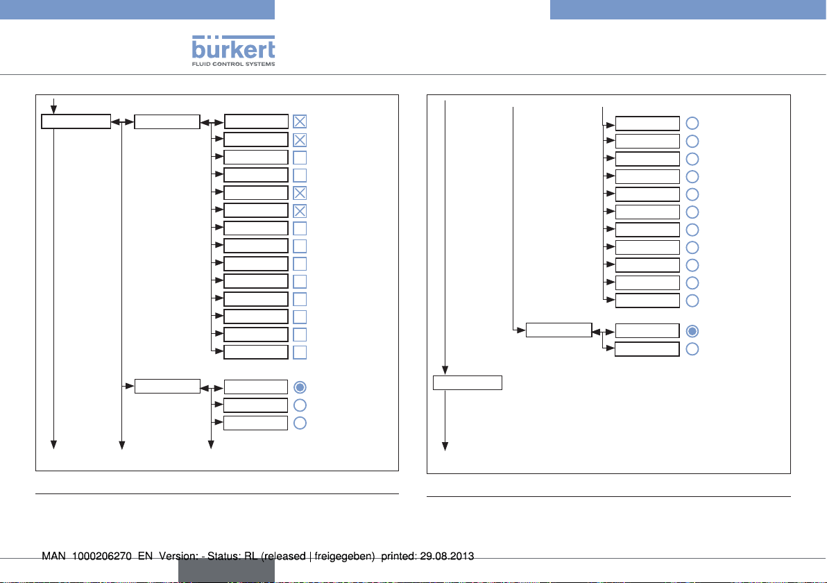
Typ 8750
Operating structure
EXTRAS
DISP.ITEMS
POS
CMD
CMD/POS
CMD/POS (t)
PV
SP
SP/PV
SP/PV (t)
CLOCK
33)
INPUT
TEMP
X.TUNE
P.TUNE
P.LIN
START-UP.ITEMS
POS
CMD
CMD/POS
SERVICE
DISP.MODE
CMD/POS (t)
Fig. 39: Operating structure FMR - 14
31) The signal type selected in the INPUT menu is displayed.
32) Only for signal type 4-20 mA (P.CONTROL→SETUP→PV-INPUT→4-20 mA)
33) Only for circuit with Pt 100 (P.CONTROL→SETUP→PV-INPUT→PT 100)
DISP.MODE
SERVICE
SIMULATION
Fig. 40: Operating structure FMR - 15
34) Not for field bus
CMD/POS (t)
PV
SP
SP/PV
SP/PV (t)
CLOCK
33)
INPUT
TEMP
X.TUNE
P.TUNE
P.LIN
normal
invers
58
english
Page 59

Typ 8750
Operating structure
SIMUALTION
SIGNAL.sim
SIGNAL.form
Extern
Sinus
Square
Triangle
Mixed
50.0 %
80.0 %
5.0 sec
CONTROL.sim
Offset
Amplitude
Periode
x.SIM
p.SIM
DIAGNOSE
D.MSG
SIM.Gain
SIM.Delay
34)
SERVICE.TIME
1.0
1.0 sec
TRAVEL.ACCU
CYCLE.COUNTER
TEMP.CHECK
CONFIG.MSG
STROKE.CHECK
Fig. 41: Operating structure FMR - 16
35) The sub-menu lists only the activated diagnostic functions.
CONFIG.MSG
ADD.DIAGNOSE
34)
TEMP.CHECK
Fig. 42: Operating structure FMR - 17
STROKE.CHECK
PV.MONITOR
POS.MONITOR
SERVICE.TIME
TRAVEL.ACCU
CYCLE.COUNTER
FAILURE
FUNC.CHECK
OUT.SPEZ
MAINTENANCE
FAILURE
FUNC.CHECK
OUT.SPEZ
MAINTENANCE
FAILURE
FUNC.CHECK
OUT.SPEZ
MAINTENANCE
english
59
Page 60

Typ 8750
Operating structure
ADD.DIAGNOSE
Fig. 43: Operating structure FMR - 18
TEMP.CHECK
STROKE.CHECK
PV.MONITOR
POS.MONITOR
FAILURE
FUNC.CHECK
OUT.SPEZ
MAINTENANCE
FAILURE
FUNC.CHECK
OUT.SPEZ
MAINTENANCE
FAILURE
FUNC.CHECK
OUT.SPEZ
MAINTENANCE
FAILURE
FUNC.CHECK
OUT.SPEZ
MAINTENANCE
ADD.DIAGNOSE
RESET.HISTORY Reset done
Activatable diagnostic functions
HISTOGRAM POS-Class
SERVICE.TIME LIMIT
TRAVEL.ACCU
Fig. 44: Operating structure FMR - 19
HISTOGRAM
SERVICE.TIME
TAVEL.ACCU
CYCLE.COUNTER
TEMP.CHECK
STROKE.CHECK
PV.MONITOR
POS.MONITOR
DIR-Class
SYSTEM-DATA
90d. 00h
NEXT M.
HISTORY
60
english
Page 61

Typ 8750
Operating structure
TAVEL.ACCU
CYCLE.COUNTER LIMIT
TEMP.CHECK CURRENT
STROKE.CHECK
Fig. 45: Operating structure FMR - 20
HUB
LIMIT
NEXT.M
HISTORY
NEXT.M
HISTORY
MAX
MIN
LIMIT
HISTORY
20.0 mm
1000000 cm
1000000
1000000
TEMP.MAX
60.0 °C
TEMP.MIN
0.0 °C
TEMP.MAX
TEMP.MAX
STROKE.CHECK MAX
POS.MONITOR DEADBAND
PV.MONITOR
Fig. 46: Operating structure FMR - 21
MIN
LIMIT
HISTORY
COMP.TIME
HISTORY
DEADBAND
COMP.TIME
HISTORY
ZERO.TOL
0.5 %
MAX.TOL
0.5 %
ZERO
MAX
2.0 %
10.0 sec
2.0 %
10.0 sec
english
61
Page 62

20. TRANSPORT, STORAGE,
PACKAGING
NOTE!
Transport damage.
▶ Inadequately protected devices may be damaged during
transportation.
▶ Protect the device against moisture and dirt in shock-resistant
packaging during transportation.
▶ Prevent the temperature from exceeding or dropping below the
permitted storage temperature.
▶ Protect the electrical interfaces of the coil and the pneumatic
connections from damage by placing protective caps on them.
Incorrect storage may damage the device.
▶ Store the device in a dry and dust-free location.
▶ Storage temperature -20 to 55°C.
Damage to the environment caused by device components
contaminated with media.
▶ Dispose of the device and packaging in an environmentally friendly
manner.
▶ Observe applicable disposal and environmental regulations.
Typ 8750
Transport, Storage, Packaging
62
english
Page 63

Page 64

www.burkert.com
 Loading...