

Page 1

Type 8741, 8742, 8746
CANopen
Configuration on the CANopen by means of EDS file
Supplement to Operating Instructions
Page 2

We reserve the right to make technical changes without notice.
Technische Änderungen vorbehalten.
Sous réserve de modifications techniques.
© 2014 Bürkert Werke GmbH
Operating Instructions 1404/00_EU-ML_00810393 / Original DE
Page 3
SensorAktorModul
Description of initiation files EDS
Description_of_InitiationFilesEDS_2 Version 1.4
page 1 / 27
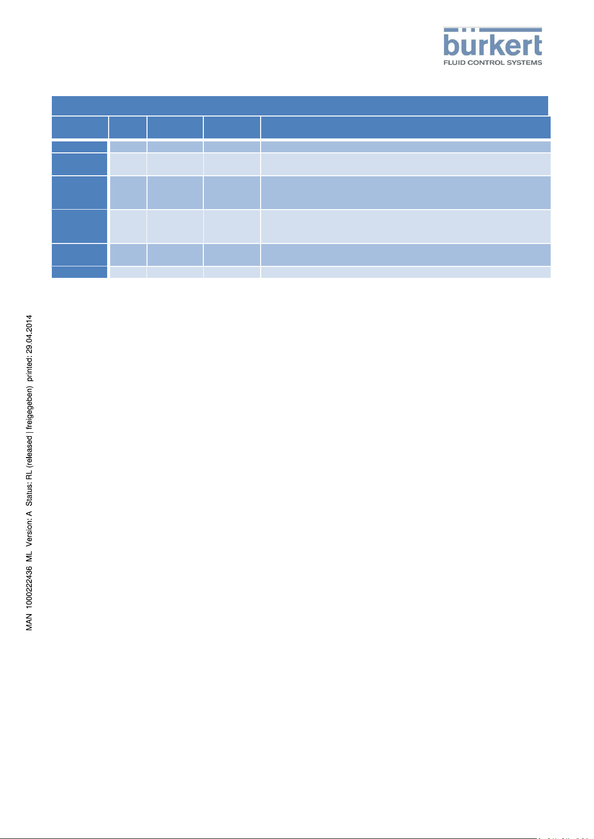
Document
version
EDS
version
Firmware
version
date
changes
1.4
1.11
A.01.00.00
2014-04-09
- eds has to be reworked to used Object range 0x2F00 instead of 0x3800 to
be conform with requirements.
1.3
1.10
A.00.09.00
2014-03-24
- Totalizer and Totalizer_Customer moved to 0x38FE and 0x38FF
- New Objects 0x2D03sub19 (0x2D04) Autotune Zero Value
- New object 0x200A Power Supply Alarm Values
1.2
1.8
A.00.08.05
2014-02-28
- Device Status Object (0x2004) reworked. Sub Indices reworked
- Device Status object includes sub index 1 with devices Namur state which
is mapped cyclic.
1.1
1.7
A.00.07.03
2013-12-09
- Device Status Object (0x2004) added
- Diagnose Object (0x2D01) some objects removed
1.0
1.6
A.00.07.00
2013-11-20
1st version
HISTORY
Contents
history ............................................................................................................................ 1
Additional information ................................................................................................... 3
Accesstype ............................................................................................................................................................................ 3
Flags ......... ............................................................................................................................................................................ 3
Accesrights ............................................................................................................................................................................ 3
objects ........................................................................................................................... 4
0x2000 ..... Buerkert Device Description Object ................................................................................................................... 4
0x2001 ..... Device Communication Object .......................................................................................................................... 4
0x2002 ..... User Configuration Object ................................................................................................................................. 5
0x2003 ..... Error Management Object ................................................................................................................................. 5
0x2004 ..... Device Status Object .......................................................................................................................................... 6
0x2005 ..... Modul Status Object .......................................................................................................................................... 7
0x200A .... Power Supply Alarm Values ............................................................................................................................... 8
0x2010 ..... Physical Group ................................................................................................................................................... 9
0x2011 ..... Loical Group ....................................................................................................................................................... 9
0x2100 ..... Get Mapping Function ....................................................................................................................................... 9
0x2101 ..... Locating Function ............................................................................................................................................... 9
0x2102 ..... Blockdownload Config Function ...................................................................................................................... 10
0x2103 ..... Persistent Storage Function ............................................................................................................................. 10
0x2220 ..... EDS ................................................................................................................................................................... 10
0x2400 ..... Sensor Type ...................................................................................................................................................... 10
0x2420 ..... No Measure Values .......................................................................................................................................... 10
0x2421 ..... No Control Values ............................................................................................................................................ 11
0x2422 ..... No Calibration Values ....................................................................................................................................... 11
0x2500 .... Current SP Nl_min ............................................................................................................................................. 11
0x2501 ..... Actual Flow Nl_min .......................................................................................................................................... 12
Page 4

SensorAktorModul
Description of initiation files EDS
Description_of_InitiationFilesEDS_2 Version 1.4
page 2 / 27
0x2502 ..... Current Dutycycle ............................................................................................................................................ 12
0x2503 ..... Medium Temperature ...................................................................................................................................... 13
0x2504 ..... Current Totalizer Nl .......................................................................................................................................... 13
0x2540 ..... SP Nl_min ......................................................................................................................................................... 14
0x2541 ..... Manual SP Nl_min ............................................................................................................................................ 14
0x2542 ..... Dutycycle .......................................................................................................................................................... 15
0x2580 ..... Generic Producer Description Object SP Nl_Min ............................................................................................. 15
0x2581 ..... Generic Producer Description Object Manual SP Nl_Min ................................................................................ 15
0x2582 ..... Generic Producer Description Object Dutycycle .............................................................................................. 15
0x2C00 ..... Actual Flow ....................................................................................................................................................... 16
0x2C10 ..... Prop Valve ........................................................................................................................................................ 16
0x2D00 .... Common ........................................................................................................................................................... 17
0x2D01 .... Diagnose........................................................................................................................................................... 17
0x2D02 .... FlowSensor ....................................................................................................................................................... 18
0x2D03 .... Sensor _1.......................................................................................................................................................... 19
0x2D04 .... Sensor _2.......................................................................................................................................................... 19
0x2D0D .... Cal_AD _1 .......................................................................................................................................................... 20
0x2D0E .... Cal_AD _2 .......................................................................................................................................................... 20
0x2D17 .... Cal_Q _1 ........................................................................................................................................................... 20
0x2D18 .... Cal_Q _2 ........................................................................................................................................................... 20
0x2D0D .... Cal_AD_Customer _1 ........................................................................................................................................ 20
0x2D0E .... Cal_AD_Customer _2 ........................................................................................................................................ 20
0x2D17 .... Cal_Q_Customer _1 ......................................................................................................................................... 20
0x2D18 .... Cal_Q_Customer _2 ......................................................................................................................................... 20
0x2D37 .... SFS7011 _1 ....................................................................................................................................................... 20
0x2D38 .... SFS7011 _2 ....................................................................................................................................................... 20
0x2D41 .... ILC _1 ................................................................................................................................................................ 21
0x2D42 .... ILC _2 ................................................................................................................................................................ 21
0x2D4B .... Sensortechnics _1 ............................................................................................................................................. 22
0x2D4C .... Sensortechnics _2 ............................................................................................................................................. 22
0x2F00 ..... Setpoint ............................................................................................................................................................ 22
0x2F11 ..... Controller ......................................................................................................................................................... 23
0x2F12 ..... Sys Param _1 .................................................................................................................................................... 23
0x2F13 ..... Sys Param _2 .................................................................................................................................................... 23
0x2FFE ..... Totalizer ............................................................................................................................................................ 24
0x2FFF ..... Totalizer Customer ........................................................................................................................................... 24
Attachment .................................................................................................................. 25
Page 5

SensorAktorModul
Description of initiation files EDS
Description_of_InitiationFilesEDS_2 Version 1.4
page 3 / 27
ADDITIONA L I N FORMATI ON
Accesstype
Defines the general CANopen access rights.
Flags
Irrelevant in CANopen mode.
Accesrights
Irrelevant in CANopen mode.
Page 6
SensorAktorModul
Description of initiation files EDS
Description_of_InitiationFilesEDS_2 Version 1.4
page 4 / 27
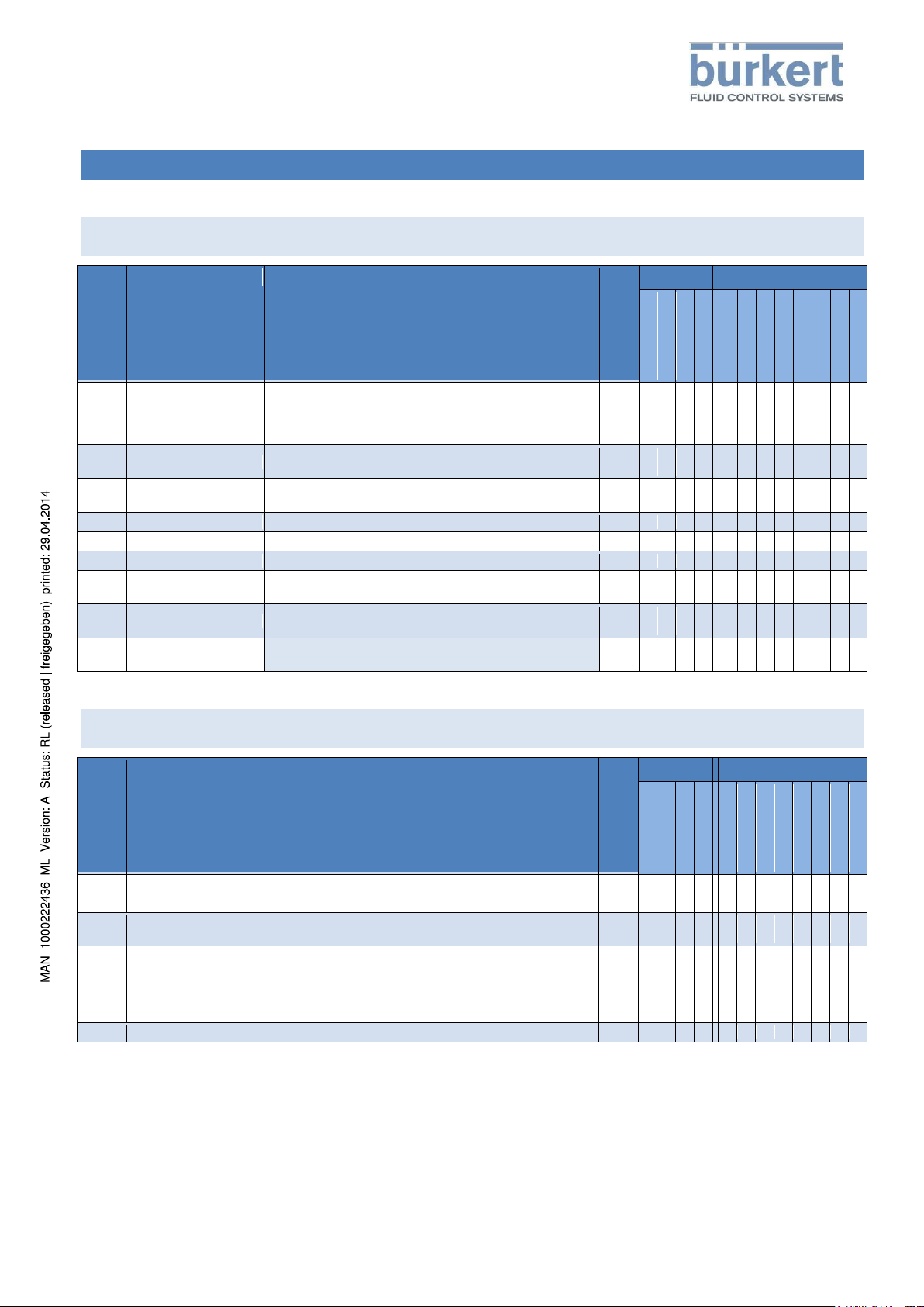
sub
name
description
accesstype
flags
accessrights
import
Import devID SIM-Card R - user
W - user
R - adv. user
W - adv. user
R - installer
W - installer
R - buerkert
W - buerkert
1
Device Name
Unique device name
It’s used to identify the device in a bueS system by name
(maybe by Buerkert Communicator)
(linked to User Configuration Object)
RO
x - x - x - x
-
2
Ident Number
Device ID No.
(linked to Common Object)
RO
x - x - x - x
- 3 Manufacture Date
(linked to Common Object)
RO
x - x - x - x
-
4
Software Ident Number
ID No. of firmware
RO
x - x - x - x -
5
Software Version
Version No. of firmware
RO
x - x - x - x - 6 Hardware Version
Version No. of hardware
RO
x - x - x - x -
7
Serial Number
Serial No. device
(linked to Common Object)
RO
x - x - x - x
- 8 Product Code
Manufacturers product code (type number)
(linked to Common Object)
RO
x - x - x - x
- 9 Product Group
Buerkert specific product group like sensor , actuator, ..
It’s used for bueS system configuration
RO
x - x - x - x
-
sub
name
description
accesstype
flags
accessrights
import
Import devID SIM-Card R - user
W - user
R - adv. user
W - adv. user
R - installer
W - installer
R - buerkert
W - buerkert
1
Baudrate
specified by CANopen (details see attachement
Baudrates)
RW
x x x x x x x x
x
2
Address
device address range 0..127
in bueS mode it’s handled automatically
RW
x x x x x x x x
x
3
bueS Mode
0 : CANopen it’s used for CANopen applications
1: bueS mode CANopen enhanced with Buerkert
specific communication parts
defined by DIP-Switch, will be read at once by starting the
device
RW
x x x x x x x
x
4
Reset
Handles several device resets (details see attachement)
RW
x x x x x x x x
OBJECTS
0x2000 Buerkert Device Description Object
0x2001 Device Communication Object
Page 7
SensorAktorModul
Description of initiation files EDS
Description_of_InitiationFilesEDS_2 Version 1.4
page 5 / 27
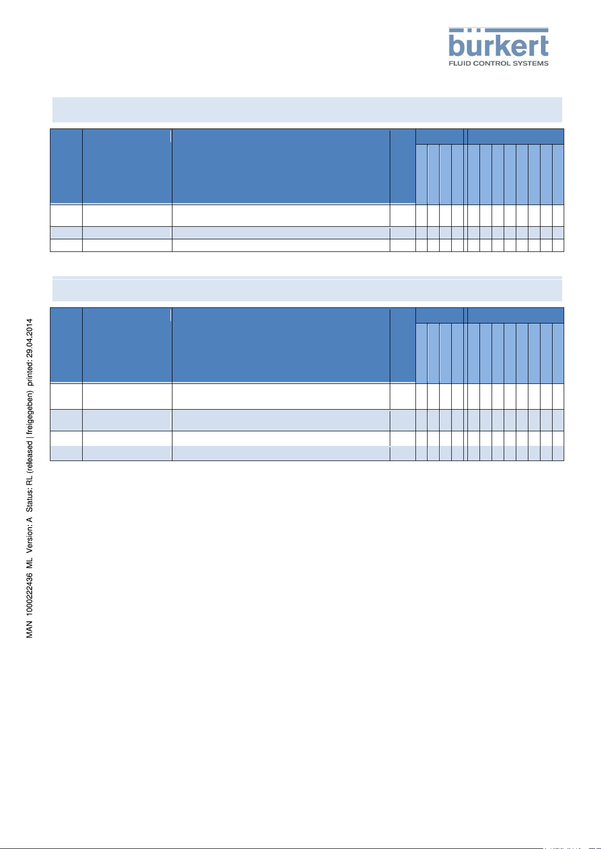
sub
name
description
accesstype
flags
accessrights
import
Import devID SIM-Card R - user
W - user
R - adv. user
W - adv. user
R - installer
W - installer
R - buerkert
W - buerkert
1
Unique Device Name
Will be taken over to Buerkert Device Description Object
during device start.
RW
x x x x x x x x
x
2
Location Information
additional user information about the devices location
RW
x x x x x x x x x 3 User Desciption
additional user information about the device
RW
x x x x x x x x x
sub
name
description
accesstype
flags accesrigths
import
Import devID SIM-Card R - user
W - user
R - adv. user
W - adv. user
R - installer
W - installer
R - buerkert
W - buerkert
1
Msg Class Switch off
part 1
Bitfield (UINT32) for switching off buerkert message
classes. Classes 0..31. 0:on, 1:off
RW
x x x x x x x
x
2
Msg Class Switch off
part 2
Bitfield (UINT32) for switching off buerkert message
classes. Classes 32..63 0:on, 1:off
RW
x x x x x x x
x
3
Msg Level Switch off
Bitfield (UINT16) for switching off buerkert messages
RW
x x x x x x x
x 4 Logbook Download
RW
x x x x x x x
x
0x2002 User Configuration Object
0x2003 Error Management Object
Page 8
SensorAktorModul
Description of initiation files EDS
Description_of_InitiationFilesEDS_2 Version 1.4
page 6 / 27
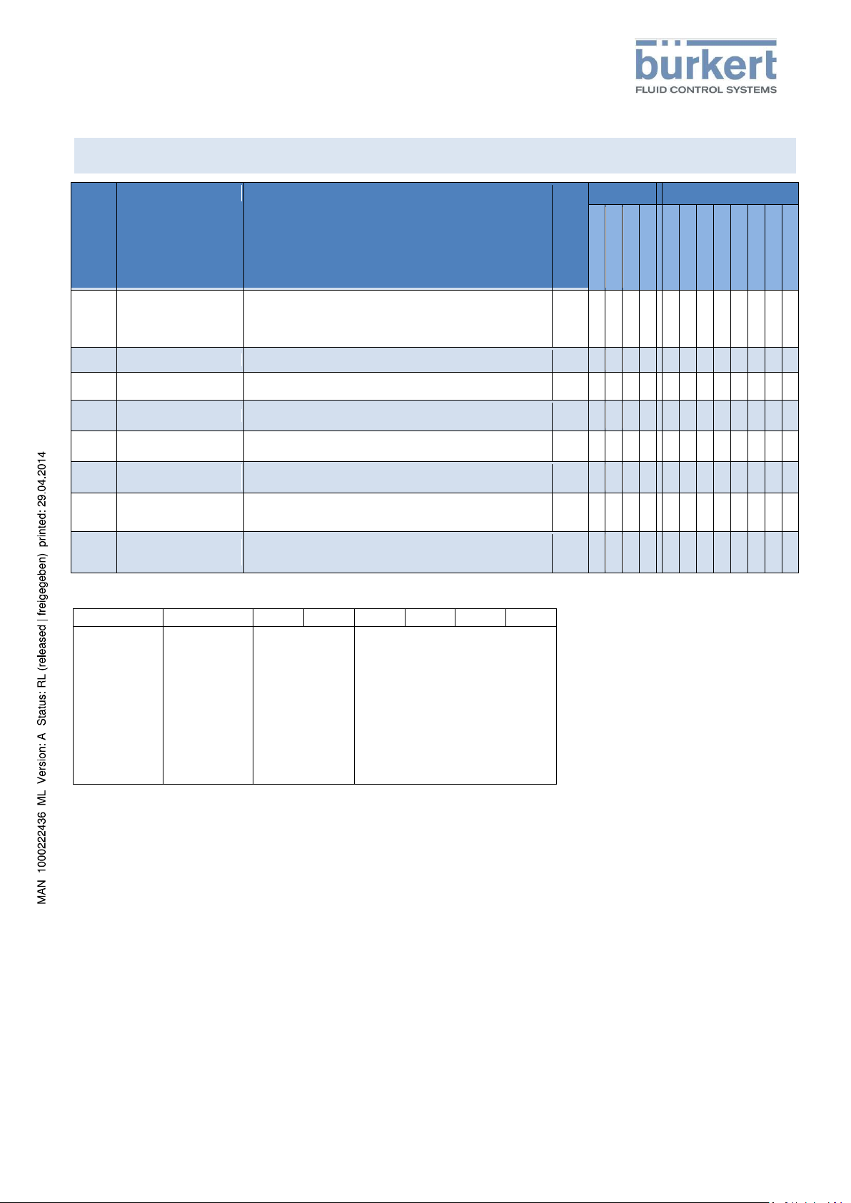
sub
name
description
accesstype
flags accesrigths
import
Import devID SIM-Card R - user
W - user
R - adv. user
W - adv. user
R - installer
W - installer
R - buerkert
W - buerkert
1
Device Status
NamurNe107
Represents the device status.
1)
Detail information for modules can be get by reading the
object 2005.
RO
x - x - x - x
-
2
Device Temperature
Devices temperature as kelvin 2)
RWR
x - x - x - x
-
3
Device Supply Voltage
Supply voltage as volt
RWR
x - x - x - x
-
4
Operation Time_[s]
Devices operating time counter as seconds
RO
- - x - x - x
x
5
Maximum Device
Temperature
Maximum inner devices temperature in kelvin during
devices lifetime 2)
RO
- - - - x - x
x
6
Minimum Device
Temperature
Minimum inner devices temperature in kelvin during devices
lifetime 2)
RO
- - - - x - x
x
7
Maximum Device
Supply Voltage
Max value of devices power supply in volts since device has
been started
RO
- - x - x - x
x
8
Minimum Device Supply
Voltage
Max value of devices power supply in volts since device has
been started
RO
- - x - x - x
x
Bit 7
Bit 6
Bit 5
Bit 4
Bit 3
Bit 2
Bit 1
Bit 0
Gateway:
0 - run
1 – stop
0 if no
gateway is
supported
by device.
F(x):
0 - run
1 – stop
0 if no F(x)
functionality
is supported
by device.
Namur mode:
0 – auto
1 – manual
2 - flashing
Namur state:
0 – normal
1 – diagnose active
2 – maintanace required
3 – out of specification
4 – warning
5 - error
0x2004 Device Status Object
1)
2) temperature as UINT16 value (0..65535). 1 digit is equivalent to 0,05 Kelvin.
Page 9

SensorAktorModul
Description of initiation files EDS
Description_of_InitiationFilesEDS_2 Version 1.4
page 7 / 27
sub
name
description
accesstype
flags accesrigths
import
Import devID SIM-Card R - user
W - user
R - adv. user
W - adv. user
R - installer
W - installer
R - buerkert
W - buerkert
0x01
..
0x..
Sub1 .. Sub..
It’s a list of device’s included modules (e.g. sensor) which
changed their status or mode during lifetime. Modules with
normal status and automatic mode are not listed by default.
They are added to the list by changing status or mode first
time. Added modules will be actuated by changing status or
mode.
Unused sub indices (list elements) are 0
Description of list elements (UINT32) 1)
RO
x - x - x - x
-
Byte 3
Byte 2
Byte 1
Byte 0
NC
Message class 2)
Module’s state and mode 3)
Module number 4)
Hardware classes
0x00
General Hardware
0x01
Current
0x02
Voltage
0x03
Temperature
0x0C
WirelessHW
0x0d
CommunicationHW
0x0e
SensorHW
0x0f
CalibrationHW
0x10
AdditionalModulHW
0x11
ActuatorHW
0x1f
DeviceSpecificHW
Software classes
0x20
General Software
0x21
State
0x22
Operating System
0x23
Storage
0x2c
WirelessSW
0x2d
CommunicationProtocolSW
0x2e
SensorSW
0x2f
CalibrationSW
0x30
AdditionalModulSW
0x31
ActuatorSW
0x32
ControllerSW
0x33
GatewaySW
0x34
FxSW
0x35
ProviderSW
0x36
RouterSW
0x3f
DeviceSpecificSW
0x2005 Modul Status Object
1) Description of list elemnts (UINT32)
2) Message class
The message class of last chang of the state or the mode
Page 10

SensorAktorModul
Description of initiation files EDS
Description_of_InitiationFilesEDS_2 Version 1.4
page 8 / 27
Bit 7
Bit 6
Bit 5
Bit 4
Bit 3
Bit 2
Bit 1
Bit 0
0 not used
0 not used
Namur mode:
0 – auto
1 – manual
2 - flashing
Namur state:
0 – normal
1 – diagnose active
2 – maintanace required
3 – out of specification
4 – warning
5 - error
0x01
CoreInterface
0x02
BueS
0x03
SubBueS
0x04
MessageDispatcher
0x05
Blackboard
0x06
StorageHandler
0x07
FlashStorageHandler
0x08
EEPromStorageHandler
0x50
Implementation
0x82
InitExit_User
0x83
FlowSensor
0x84
Controller
0x85
PropValve
0x86
Autotune
0x87
DeviceDiagnose
sub
name
description
accesstype
flags accesrigths
import
Import devID SIM-Card R - user
W - user
R - adv. user
W - adv. user
R - installer
W - installer
R - buerkert
W - buerkert
1
Voltage error limit high
A device error will be generated if power supply passes this
value as float32 in volts
RO
- - x - x - x
x
2
Voltage error limit low
A device error will be generated if power supply falls below
this value as float32 in volts
RO
- - x - x - x
x
3
Voltage warning limit
high
A device warning will be generated if power supply passes
this value as float32 in volts
RW
- - x - x x x
x
4
Voltage warning limit
high
A device warning will be generated if power supply falls
below this value as float32 in volts
RW
- - x - x x x
x
3) Module’s state and mode
4) Module number
0x200A Power Supply Alarm Values
Page 11

SensorAktorModul
Description of initiation files EDS
Description_of_InitiationFilesEDS_2 Version 1.4
page 9 / 27
sub
name
description
accesstype
flags accesrigths
import
Import devID SIM-Card R - user
W - user
R - adv. user
W - adv. user
R - installer
W - installer
R - buerkert
W - buerkert
0
Physical Group
It’s used for automatic configurate a bueS system.
Several physical device groups can be defined to configure
a bueS system.
RW
x x x x x x x x
x
sub
name
description
accesstype
flags accesrigths
import
Import devID SIM-Card R - user
W - user
R - adv. user
W - adv. user
R - installer
W - installer
R - buerkert
W - buerkert
0
Logical Group
It’s used for automatic configurate a bueS system.
Several logical device groups can be defined to configure a
bueS system.
RW
x x x x x x x x
x
sub
name
description
accesstype
flags
accessrights
import
Import devID SIM-Card R - user
W - user
R - adv. user
W - adv. user
R - installer
W - installer
R - buerkert
W - buerkert
1
Index/Subindex
RW
x x x x x x x x 2 result
RW
x x x x x x x x 3 call/cancel
RW
x x x x x x x x
sub
name
description
accesstype
flags
accessrights
import
Import devID SIM-Card R - user
W - user
R - adv. user
W - adv. user
R - installer
W - installer
R - buerkert
W - buerkert
1
call/cancel
bueS internal function
RW
x x x x x x x x
0x2010 Physical Group
0x2011 Loical Group
0x2100 Get Mapping Function
bueS internal function.
0x2101 Locating Function
Function to locate a device. E.g. let the devices LED blink for several time.
Page 12

SensorAktorModul
Description of initiation files EDS
Description_of_InitiationFilesEDS_2 Version 1.4
page 10 / 27
sub
name
description
accesstype
flags
accessrights
import
Import devID SIM-Card R - user
W - user
R - adv. user
W - adv. user
R - installer
W - installer
R - buerkert
W - buerkert
1
Action
RW
x x x x x x x
x 2 Index/Subindex
RW
x x x x x x x
x
3
result
RO
x - x - x - x - 4
call/cancel
RW
x x x x x x x
x
sub
name
description
accesstype
flags
accessrights
import
Import devID SIM-Card R - user
W - user
R - adv. user
W - adv. user
R - installer
W - installer
R - buerkert
W - buerkert
1
Storage Group
Data are separated into several storage groups
definitions see attachement “Storage groups”
RW
x x x x x x x
x
2
Access Control
1: read data
2: write data
3: load default values
4: format memory
Location is defined by StorageGroup.
Reorganize the defined storage (it’s for reducing the
accesstime to the storage, especially after a firmware
update)
Value 0xFF of StorageGroup handles all locations.
RW
x x x x x x x
x
3
result
« 0xFF » function is still running
value !=0xFF function is finished
value has to be read acyclic
RO
x - x - x - x
-
4
call/cancel
1: call the function
result value of 0xFF has to be checked before
«0» : has to be set after function is finished
(result value is resetted to 0xFF)
RW
x x x x x x x
x
0x2102 Blockdownload Config Function
0x2103 Persistent Storage Function
It’s used for handling of data which are stored persistent.
0x2220 EDS
no objects
0x2400 Sensor Type
no objects
0x2420 No Measure Values
no objects
Page 13

SensorAktorModul
Description of initiation files EDS
Description_of_InitiationFilesEDS_2 Version 1.4
page 11 / 27
sub
name
description
accesstype
flags
accessrights
import
Import devID SIM-Card R - user
W - user
R - adv. user
W - adv. user
R - installer
W - installer
R - buerkert
W - buerkert
1
current_w
« 0 » internal used setpoint
RWR
x - x - x - x -
2
Unit
« 0xA04700 » bueS specific SI unit : Nl/min
Other units are handled by display
or Buerkert Communicator
RO
x - x - x - x
-
3
Name
« Current Setpoint » objects name
RO
x - x - x - x -
4
Classification
« 0x0003 » bueS specific
RO
x - x - x - x - 5 Datatype
« 0x08 » REAL32
RO
x - x - x - x - 6 Precision
bueS specific
RO
x - x - x - x -
7
Feature Group
« 0 » bueS specific
Is used for automatic configuration
of bueS systems
RW
x x x x x x x x
x
0x2421 No Control Values
no objects
0x2422 No Calibration Values
no objects
0x2500 Current SP Nl_min
Cyclic current used setpoint as REAL32 for closed loop control. It represents the used setpoint which is manipulated e.g.
rise time. For more information see 0x2F11 Controller Object.
It’s mapped by TPDO 1 (0x1A01sub1).
Object can be used for automatically bueS configuration in a bueS system.
Page 14

SensorAktorModul
Description of initiation files EDS
Description_of_InitiationFilesEDS_2 Version 1.4
page 12 / 27
sub
name
description
accesstype
flags
accessrights
import
Import devID SIM-Card R - user
W - user
R - adv. user
W - adv. user
R - installer
W - installer
R - buerkert
W - buerkert
1
x
« 0 » actual flow
RWR
x - x - x - x -
2
Unit
« 0xA04700 » bueS specific SI unit : Nl/min
Other units are handled by display
or Buerkert Communicator
RO
x - x - x - x
-
3
Name
« Actual Flow » objects name
RO
x - x - x - x - 4 Classification
« 0x0003 » bueS specific
RO
x - x - x - x -
5
Datatype
« 0x08 » REAL32
RO
x - x - x - x - 6 Precision
bueS specific
RO
x - x - x - x -
7
Feature Group
« 0 » bueS specific
Is used for automatic configuration
of bueS systems
RW
x x x x x x x x
x
sub
name
description
accesstype
flags
accessrights
import
Import devID SIM-Card R - user
W - user
R - adv. user
W - adv. user
R - installer
W - installer
R - buerkert
W - buerkert
1
y2
« 0 » valves dutycycle (actuating
variable)
RWR
x - x - x - x
-
2
Unit
« 0xFE000000 » bueS specific : value as %
Other units are handled by display
or Buerkert Communicator
RO
x - x - x - x
-
3
Name
« Current Dutycycle » objects name
RO
x - x - x - x - 4 Classification
« 0x000E » bueS specific
RO
x - x - x - x - 5 Datatype
« 0x08 » REAL32
RO
x - x - x - x - 6 Precision
bueS specific
RO
x - x - x - x -
7
Feature Group
« 0 » bueS specific
Is used for automatic configuration
of bueS systems
RW
x x x x x x x x
x
0x2501 Actual Flow Nl_min
Cyclic actual flow as REAL32. It’s mapped by TPDO 0 (0x1A00sub1).
Object can be used for automatically bueS configuration in a bueS system.
0x2502 Current Dutycycle
Cyclic current valves duty cycle as REAL32. It’s mapped by TPDO 1 (0x1A01sub2).
Object can be used for automatically bueS configuration in a bueS system.
Page 15

SensorAktorModul
Description of initiation files EDS
Description_of_InitiationFilesEDS_2 Version 1.4
page 13 / 27
sub
name
description
accesstype
flags
accessrights
import
Import devID SIM-Card R - user
W - user
R - adv. user
W - adv. user
R - installer
W - installer
R - buerkert
W - buerkert
1
Medium Temp
« 0 » temperature of the medium
0..3276 Kelvin is scaled to 0 65535
Resolution is 0.05 Kelvin
RWR
x - x - x - x
-
2
Unit
« 0x050000» bueS specific SI unit : Kelvin
Other units are handled by display
or Buerkert Communicator
RO
x - x - x - x
-
3
Name
« Medium Temp.» objects name
RO
x - x - x - x - 4 Classification
« 0x0001» bueS specific
RO
x - x - x - x -
5
Datatype
« 0x06 » UINT16
RO
x - x - x - x - 6 Precision
bueS specific
RO
x - x - x - x -
7
Feature Group
« 0 » bueS specific
Is used for automatic configuration
of bueS systems
RW
x x x x x x x x
x
sub
name
description
accesstype
flags
accessrights
import
Import devID SIM-Card R - user
W - user
R - adv. user
W - adv. user
R - installer
W - installer
R - buerkert
W - buerkert
1
Totalizer
« 0 » totalizer value of the selected gas
(see FlowSensor Object
0x2D02sub1)
RWR
x - x - x - x - 2
Unit
« 0xA00000 » bueS specific SI unit : Nl
Other units are handled by display
or Buerkert Communicator
RO
x - x - x - x
-
3
Name
« Current Totalizer » objects name
RO
x - x - x - x - 4 Classification
« 0x0010 » bueS specific
RO
x - x - x - x - 5 Datatype
« 0x08 » REAL32
RO
x - x - x - x -
6
Precision
bueS specific
RO
x - x - x - x -
7
Feature Group
« 0 » bueS specific
Is used for automatic configuration
of bueS systems
RW
x x x x x x x x
x
0x2503 Medium Temperature
Cyclic medium temperature as REAL32. It’s mapped by TPDO 0 (0x1A00sub2).
Object can be used for automatically bueS configuration in a bueS system.
0x2504 Current Totalizer Nl
Cyclic current totalizer as REAL32. It’s mapped by TPDO 2 (0x1A02sub2).
Object can be used for automatically bueS configuration in a bueS system.
Page 16

SensorAktorModul
Description of initiation files EDS
Description_of_InitiationFilesEDS_2 Version 1.4
page 14 / 27
sub
name
description
accesstype
flags
accessrights
import
Import devID SIM-Card R - user
W - user
R - adv. user
W - adv. user
R - installer
W - installer
R - buerkert
W - buerkert
1
w
« 0 » controllers setpoint
(is used if it’s selected by setpoint
source of Controller Object
0x3811sub3)
RWW
x x x x x x x
x
2
Unit
« 0xA04700 » bueS specific SI unit : Nl/min
Other units are handled by display or
Buerkert Communicator
RO
x - x - x - x
-
3
Name
« Setpoint » objects name
RO
x - x - x - x - 4 Classification
« 0x0003 » bueS specific
RO
x - x - x - x -
5
Datatype
« 0x08 » REAL32
RO
x - x - x - x - 6 Precision
bueS specific
RO
x - x - x - x -
7
Feature Group
« 0 » bueS specific
Is used for automatic configuration
of bueS systems
RW
x x x x x x x x
x
8
Res lower Limit
« 0 »
RO
x - x - x - x -
9
Res upper Limit
value depends on QNom of actual
calibration curve
RO
x - x - x - x
-
sub
name
description
accesstype
flags
accessrights
import
Import devID SIM-Card R - user
W - user
R - adv. user
W - adv. user
R - installer
W - installer
R - buerkert
W - buerkert
1
manual_w
« 0 » controllers setpoint
It’s used in bueS mode for manual setpoint
manipulation by e.g. display
(is used if it’s selected by setpoint source of
Controller Object 0x3811sub3)
RWW
x x x x x x x
x
2
Unit
« 0xA04700 » bueS specific SI unit : Nl/min
Other units are handled by display
or Buerkert Communicator
RO
x - x - x - x
-
3
Name
« Manual Setpoint » objects name
RO
x - x - x - x - 4 Classification
« 0x0003 » bueS specific
RO
x - x - x - x -
5
Datatype
« 0x08 » REAL32
RO
x - x - x - x - 6 Precision
bueS specific
RO
x - x - x - x -
7
Feature Group
« 0 » bueS specific
Is used for automatic configuration
of bueS systems
RW
x x x x x x x x
X
8
Res lower Limit
« 0 »
RO
x - x - x - x -
9
Res upper Limit
value depends on QNom of actual
calibration curve
RO
x - x - x - x
-
0x2540 SP Nl_min
Cyclic setpoint as REAL32. It’s mapped by RPDO 0 (0x1600sub1).
Object can be used for automatically bueS configuration in a bueS system.
0x2541 Manual SP Nl_min
It’s used for bueS mode.
Cyclic manual setpoint as REAL32, it’s used by display to change the setpoint manually.
Object can be used for automatically bueS configuration in a bueS system.
Page 17

SensorAktorModul
Description of initiation files EDS
Description_of_InitiationFilesEDS_2 Version 1.4
page 15 / 27
sub
name
description
accesstype
flags
accessrights
import
Import devID SIM-Card R - user
W - user
R - adv. user
W - adv. user
R - installer
W - installer
R - buerkert
W - buerkert
1
y2
« 0 » valves dutycycle (actuating variable)
In open loop control or during
calibration
RWW
x x x x x x x
x
2
Unit
« 0xFE000000» bueS specific : value as %
Other units are handled by display or
Buerkert Communicator
RO
x - x - x - x
-
3
Name
« Dutycycle » objects name
RO
x - x - x - x - 4 Classification
« 0x000E » bueS specific
RO
x - x - x - x -
5
Datatype
« 0x08 » REAL32
RO
x - x - x - x - 6 Precision
bueS specific
RO
x - x - x - x -
7
Feature Group
« 0 » bueS specific
Is used for automatic configuration
of bueS systems
RW
x x x x x x x x
x
8
Res lower Limit
« 0 »
RO
x - x - x - x -
9
Res upper Limit
« 100 »
RO
x - x - x - x -
sub
name
description
accesstype
flags
accessrights
import
Import devID SIM-Card R - user
W - user
R - adv. user
W - adv. user
R - installer
W - installer
R - buerkert
W - buerkert
1
Unique Device Name
RW
x x x x x x x x x
2
Sensor Index
RW
x x x x x x x x x 3 Manual Config Flag
RW
x x x x x x x x x
0x2542 Dutycycle
Cyclic valves duty cycle as REAL32. It’s mapped by RPDO 1 (0x1601sub1).
It’s used for open loop control and calibration.
Object can be used for automatically bueS configuration in a bueS system.
0x2580 Generic Producer Description Object SP Nl_Min
0x2581 Generic Producer Description Object Manual SP Nl_Min
0x2582 Generic Producer Description Object Dutycycle
Page 18

SensorAktorModul
Description of initiation files EDS
Description_of_InitiationFilesEDS_2 Version 1.4
page 16 / 27
sub
name
description
accesstype
flags
accessrights
import
Import devID SIM-Card R - user
W - user
R - adv. user
W - adv. user
R - installer
W - installer
R - buerkert
W - buerkert
1
Actual Flow_x
Actual flow in choosen unit (sub2)
RWR
x - x - x - x -
2
Unit
Describe the objects used unit.
Unit is stored for every calibration curve (see Sensor _x
Object 0x2D03.. 0x2D0C subF). This unit is equal to the
selected gas.
Details of unit values see attachement.
RW
x x x x x x x
x
3
Flow Full Scale
devices nominal flow of selected gas
RO
x - x - x - x - 4 Sens Raw Flow
Sensor raw flow value
RWR
- - x - x - x -
5
Sens Raw Temp
Sensor raw temperature value
RWR
- - - - x - x -
sub
name
description
accesstype
flags
accessrights
import
Import devID SIM-Card R - user
W - user
R - adv. user
W - adv. user
R - installer
W - installer
R - buerkert
W - buerkert
1
Frequency Min
used minimal frequency for valves dutycycle
RO
x - x - x - x x 2 Frequency Max
used maximal frequency for valves dutycycle
RO
x - x - x - x x
3
Frequency Shift
« 0 » it’s possible to shift the frequency in range of +/-
10.0%
It’s used by customer to manipulate the valves
frequency
RW
x - x x x x x
x
4
Valve Type
Assambled valve type
RW
x - x - x x x x 5 Valve Coil
Coil of assambled valve
RW
x - x - x x x x 6 Valve Orifice
Orifice of assambled valve
RW
x - x - x x x x
7
Leak Tight Pres
Leak tight pressure of assembled valve as bar rel.
RO
- - x - x - x
x
8
Actuator Override
Describe the valves behavior.
« 0 » EnActuatorOverride_Automatic
(use dutycycle input object 2541sub1)
1 EnActuatorOverride_CloseValve
2 EnActuatorOverride_OpenValve
3 EnActuatorOverride_Hold (freeze last value)
RW
x x x x x x x
x
0x2C00 Actual Flow
Cyclic actual flow as REAL32. It’s mapped by TPDO 2 (0x1A02sub1).
It’s used for CANopen mode. The actual flow is transmitted in the choosen unit (sub2).
Object can be used for automatically bueS configuration in a bueS system.
0x2C10 Prop Valve
Page 19

SensorAktorModul
Description of initiation files EDS
Description_of_InitiationFilesEDS_2 Version 1.4
page 17 / 27
sub
name
description
accesstype
flags
accessrights
import
Import devID SIM-Card R - user
W - user
R - adv. user
W - adv. user
R - installer
W - installer
R - buerkert
W - buerkert
1
Device Type
Buerkert specific device types e.g. 8741, 8742…
Value will be adopted to Product Code of Buerkert Device
Description Object during device start.
RO
x - x - x - x
x
2
Ident Number
Buerkert specific devices ID No.
Value will be adopted to Ident Number of Buerkert Device
Description Object during device start.
RO
x - x - x - x x 3
Serial Number
Buerkert specific devices SN.
Value will be adopted to Serial Number of Buerkert Device
Description Object during device start.
RO
x - x - x - x
x
4
Manufacture Date
Buerkert date of manufacturing
Value will be adopted to Manufacture Date of Buerkert
Device Description Object during device start.
RO
x - x - x - x
x
5
Sample Time Ms
Controllers sample time in ms
RO
- - x - x - x x
6
Autotune Active
It’s used for starting a device autotune. During autotune the
system is analysed and new controller paramters are
identified.
1: start autotune
after autotune normal mode will be reactivated
(value is resetted automatically)
0: normal mode (autotune inactive)
RW
x - x x x x x
x
7
Control Device
Specifies the general device class
0: Measuring device
1: Control device
RO
x - x - x - x
x
sub
name
description
accesstype
flags accesrigths
import
Import devID SIM-Card R - user
W - user
R - adv. user
W - adv. user
R - installer
W - installer
R - buerkert
W - buerkert
1
Medium Temperature
Measure Time sec
Cycle time for medium temperature measurement
RW
x
x x - x - x x x
x
B
Device Temperature
Limit Low
A device warning will be generated if device temperature
falls below this value in degree celsius as float32 value
RO
- - - - x - x
x
C
Device Temperature
Limit High
A device warning will be generated if device temperature
passes this value in degree celsius as float32 value
RO
- - - - x - x
x
0x2D00 Common
0x2D01 Diagnose
Page 20

SensorAktorModul
Description of initiation files EDS
Description_of_InitiationFilesEDS_2 Version 1.4
page 18 / 27
sub
name
description
accesstype
flags
accessrights
import
Import devID SIM-Card R - user
W - user
R - adv. user
W - adv. user
R - installer
W - installer
R - buerkert
W - buerkert
1
Acitve Calibration Curve
Specifies the choosen gas calibration (1..x).
The amount of the supported gas calibrations of the device
is specified by the possible max value.
RW
x
x x x x x x x x
x
2
Sensor Type
0: SFS 7011
1: Inline Chip Digital
RO
- - x - x - x
x
3
Calibration Active
0: normal mode (calibration inactive)
1: calibration active
FlowSensor without temperature compensation has to
be set by testbench during calibration
RW
x - x x x x x
x
4
Output Filter
filter for the actual flow
since EDS 1.4 cutoff frequency fg in Hz as FLOAT32
(default 5Hz)
RW
x
x x - x x x x x
x 5 Medium Temp Limit
Low
A device warning will be generated if medium temperature
falls below this value as float32 in degree celsius
RO
- - - - x - x
x
6
Medium Temp Limit
High
A device warning will be generated if medium temperature
passes this value as float32 in degree celsius
RO
- - - - x - x
x
0x2D02 FlowSensor
Detailed information see attachement: General Description of flow sensor.
Page 21

SensorAktorModul
Description of initiation files EDS
Description_of_InitiationFilesEDS_2 Version 1.4
page 19 / 27
sub
name
description
accesstype
flags
accessrights
import
Import devID SIM-Card R - user
W - user
R - adv. user
W - adv. user
R - installer
W - installer
R - buerkert
W - buerkert
1
Curve Calibrated
Defines if the curve is calibrated by manufacturer.
If it isn’t, a customer specified calibration is impossible.
0: curve isn’t calibrated
1: curve is calibrated
RW
x - x - x - x
x
2
Used Cal Points
Defines the amount of used calibration points from the
manufacturers calibration curve.
RO
- - - - x - x
x
3
Calibration Medium
Name of the medium used for calibration by manufacturer
RO
x - x - x - x x 4 Medium
Name of medium for which the device is calibrated
RO
x - x - x - x x 5 Medium Density
Density of medium for which the device is calibrated
RO
x - x - x - x x
6
Temp Komp A
Temperature compensation factor A for the medium for
which the device is calibrated
RO
- - - - x - x
x 7 Temp Komp B
Temperature compensation factor B for the medium for
which the device is calibrated
RO
- - - - x - x
x 8 Cal Temperature
Temperature while device was calibrated in degree celcius
as float32 value.
RO
- - x - x - x
x
9
Cal Pres
Pressure for which the device is calibrated (inlet pressure)
RO
x - x - x - x x
A
Assembly Pos
Position at which the device was calibrated.
Details see attachment “Assembly position”
RO
x - x - x - x
x
B
QNom Min [Nl/min]
Minimum value for QNom
RO
- - x - x - x x C QNom Max [Nl/min]
Maximum value for QNom
RO
- - x - x - x x
D
QNom [Nl/min]
Devices nominal flow rate in Nl/min
Possible range is defined by QNom Min and QNom Max
RW
x
x x - x x x x x
x
E
Span
Defines the sensors span in percent as REAL32 (0.1% –
20%).
e.g. a span of 1:50 is represented by a value of 2 %
it defines the minimum value for which the calibration is
usable
RO
- - x - x - x
x
F
Used Unit
Describes the used unit.
By default the used unit is equal for which the device is
ordered.
The unit can be changed by customer.
See attachment: flow units
RW
x
x - - x x x x x
x
10
Cal Date
Manufacturers date of calibration
RO
- - x - x - x x
11
Cal Site
Manufacturers site of calibration as number
RO
- - x - x - x x
12
Calibrator
Manufacturers calibrator as number
RO
- - - - x - x x
13
Cal Number
Manufacturers calibration number
RO
- - x - x - x x
14
Medium Name
Customer
Name of medium which is used by customer
If not other specified the value is set by testbench same like
the Calibration Medium (sub3).
RW
x x - x x x x x
x
15
Userdefined Curve
Active
Defines if customers calibration curve is active.
0: manufacturer calibration curve active
1: user defined calibration curve active
RW
- - x x x x x
x
16
Userdefined Used Cal
Points
Defines the amount of used calibration points from the user
defined calibration curve.
RW
- - x x x x x
x
17
Userdefined Cal
Temperature
Temperature while device was calibrated by user in degree
celcius as float32 value.
RW
- - x x x x x
x
18
Userdefined Cal Date
Date of users calibration
RW
- - x x x x x x
19
Autotune Zero Value
Sensor raw value during last autotune
RW
- - - - - - x x
0x2D03 Sensor _1
0x2D04 Sensor _2
Detailed information see attachment: General Description of flow sensor.
Page 22

SensorAktorModul
Description of initiation files EDS
Description_of_InitiationFilesEDS_2 Version 1.4
page 20 / 27
sub
name
description
accesstype
flags
accessrights
import
Import devID SIM-Card R - user
W - user
R - adv. user
W - adv. user
R - installer
W - installer
R - buerkert
W - buerkert
0x01
..
0x20
sub1..sub32
Array of calibration values. (e.g. sub1 is the calibration
value for calibration point 1 of according calibration curve )
Cal_AD _x calibration points of sensors raw values
Cal_Q _x calibration points of flow values in Nl/min
RO
- - - - x - x
x
sub
name
description
accesstype
flags
accessrights
import
Import devID SIM-Card R - user
W - user
R - adv. user
W - adv. user
R - installer
W - installer
R - buerkert
W - buerkert
0x01
..
0x20
sub1..sub32
Array of customer calibration values. (e.g. sub1 is the
calibration value for calibration point 1 of according
customer calibration curve)
Cal_AD_Customer _x calibration points of sensors raw
values
Cal_Q_Customer _x calibration points of flow values in
Nl/min
RW
- - x x x x x
x
0x2D0D Cal_AD _1
0x2D0E Cal_AD _2
0x2D17 Cal_Q _1
0x2D18 Cal_Q _2
Detailed information see attachement: General Description of flow sensor.
0x2D0D Cal_AD_Customer _1
0x2D0E Cal_AD_Customer _2
0x2D17 Cal_Q_Customer _1
0x2D18 Cal_Q_Customer _2
Detailed information see attachement: General Description of flow sensor.
0x2D37 SFS7011 _1
0x2D38 SFS7011 _2
Detailed information see attachement: General Description of flow sensor.
Page 23

SensorAktorModul
Description of initiation files EDS
Description_of_InitiationFilesEDS_2 Version 1.4
page 21 / 27
sub
name
description
accesstype
flags
accessrights
import
Import devID SIM-Card R - user
W - user
R - adv. user
W - adv. user
R - installer
W - installer
R - buerkert
W - buerkert
1
Operation Mode
Voltage reference for sensor (TP3/Bandgap)
See attachment: “SFS7011 operation mode”
RO
- - - - x - x
x
2
Gain
Gain for the sensor value
RO
- - - - x - x x
3
Multiplexer
Connection of thermopiles (difference, sum, etc.)
See attachment: “SFS7011 heaterSFS7011 multiplexer”
RO
- - - - x - x
x 4 Heaterpower
Electrical power of the heater
See attachment: “SFS7011 heater”
RO
- - - - x - x
x
5
Error Code
Sensor specific error code
0: no error occured
RO
- - - - x - x
-
sub
name
description
accesstype
flags
accessrights
import
Import devID SIM-Card R - user
W - user
R - adv. user
W - adv. user
R - installer
W - installer
R - buerkert
W - buerkert
1
Diag Channel
Channel no. which is converted for diagnose purposes
RO
- - - - x - x x
2
Raw Diag Ch
Value of diagnose channel chosen above
RO
- - - - x - x x 3 Gain Ch0
Gain setting for adc ch0
RO
- - - - x - x x 4 Gain Ch1
Gain setting for adc ch1
RO
- - - - x - x x 5 Gain Diag
Gain setting for diagnose channel
RO
- - - - x - x x
6
GPIO Status
Status of the available gpio pins (set/reset)
RO
- - - - x - x x 7 Regression Line Offset
Offset modification for temperature compensation
RO
- - - - x - x x
8
Error Code
Sensor specific error code
0: no error occured
RO
- - - - x - x
-
Error Codes:
ui16ErrorCode|=0x0001; // not able to write the factory settings
ui16ErrorCode|=0x0002; // sensor will run with the default resolution of 9 bit!
ui16ErrorCode|=0x0004; // Wrong user data!
ui16ErrorCode|=0x0008; // No measurement triggered!
ui16ErrorCode|=0x0010; // CRC error!
ui16ErrorCode|=0x0020; // Could not read data from sensor
ui16ErrorCode|=0x0080; // No communication interface available!
0x2D41 ILC _1
0x2D42 ILC _2
Detailed information see attachement: General Description of flow sensor.
Error Codes: unused.
Page 24

SensorAktorModul
Description of initiation files EDS
Description_of_InitiationFilesEDS_2 Version 1.4
page 22 / 27
sub
name
description
accesstype
flags
accessrights
import
Import devID SIM-Card R - user
W - user
R - adv. user
W - adv. user
R - installer
W - installer
R - buerkert
W - buerkert
1
Raw Temp Value At 0
Degree
Sensor raw temperature value at 0 degree celc
RO
- - - - x - x
x
2
Filter Setup
Numbers of samples used to filter the flow raw value
Default 1
RO
- - - - x - x
x
3
Error Code
Sensor specific error code
0: no error occured
RO
- - - - x - x
-
sub
name
description
accesstype
flags
accessrights
import
Import devID SIM-Card R - user
W - user
R - adv. user
W - adv. user
R - installer
W - installer
R - buerkert
W - buerkert
1
Setpoint_w
Setpoint_w value used by CANopen communication.
The sepoints unit referes to Unit of Actual Flow
(0x2C00sub2).
The maximum possible setpoint corresponds to Flow Full
Scale of ActualFlow (0x2C00sub3)
RWW
x x x x x x x
x
0x2D4B Sensortechnics _1
0x2D4C Sensortechnics _2
Detailed information see attachement: General Description of flow sensor.
Error Codes:
ui16ErrorCode|=0x0001; // Unknown package received from SAM
Ui16ErrorCode|=0x0002; // Invalid package size received from SAM
ui16ErrorCode|=0x0004; // CRC error in received package from SAM
ui16ErrorCode|=0x0008; // Communication error between front-end- and back-end-processor
ui16ErrorCode|=0x0010; // No valid serial number
ui16ErrorCode|=0x0020; // RX buffer overflow
ui16ErrorCode|=0x0040; // Invalid value
ui16ErrorCode|=0x0080; // Current below limit
ui16ErrorCode|=0x0100; // CRC Error
ui16ErrorCode|=0x0200; // Could not read from sensor at all!
ui16ErrorCode|=0x8000; // unknown error package!
0x2F00 Setpoint
Cyclic setpoint as REAL32. It’s mapped by RPDO 2 (0x1602sub1).
Page 25

SensorAktorModul
Description of initiation files EDS
Description_of_InitiationFilesEDS_2 Version 1.4
page 23 / 27
sub
name
description
accesstype
flags
accessrights
import
Import devID SIM-Card R - user
W - user
R - adv. user
W - adv. user
R - installer
W - installer
R - buerkert
W - buerkert
1
kp
Controller parameter
RW
x x - - x x x x x x 2 tn
Controller parameter
RW
x x - - x x x x x x
3
SP Source
Defines which source is used as setpoint.
See attachement: “Setpoint source”
RW
x
x x x x x x x x
x
4
Stored SP Percent
Value in % of QNom.
It can be used as setpoint source (maybe in a stand alone
system).
see sub3
RW
x
x x x x x x x x
x
5
Threshold Percent
Defines the controllers threshold in percent as REAL32
(0..30%).
Deactivated (0%) as default.
The threshold of the controller decide, below which value
(as percent of QNominal) the actuating variable is set to
zero directly (y2 = 0). The used setpoint is manipulated by
max positive (negative) rise time before.
RW
x
x x - x x x x x
x
6
Max Positive Rise Time
Sec
Specifies the maximal positive rise time of an setpoint jump
from 0% to 100% in seconds. This rise time is used for
every positive setpoint jump. By a value of 0, the setpoint
isn’t manipulated by this functionality.
RW
x
x x - x x x x x
x
7
Max Negative Rise
Time Sec
Specifies the maximal negative rise time of an setpoint jump
from 0% to -100% in seconds. This rise time is used for
every negative setpoint jump. By a value of 0, the setpoint
isn’t manipulated by this functionality.
RW
x
x x - x x x x x
x
8
Control In xFilter
filter for the actual flow which is used for the closed loop
controller as input value
new since EDS 1.4 cutoff frequency fg in Hz as FLOAT32
(default deactivated 0 Hz)
RW
x
x x - x - x x x
x
sub
name
description
accesstype
flags
accessrights
import
Import devID SIM-Card R - user
W - user
R - adv. user
W - adv. user
R - installer
W - installer
R - buerkert
W - buerkert
1
Dutycycle1
value duty cycle for 0% flow
RW
- - - - x x x x 2 Dutycycle2
value duty cycle for 25% flow
RW
- - - - x x x x 3 Dutycycle3
value duty cycle for 50% flow
RW
- - - - x x x x
4
Dutycycle4
value duty cycle for 75% flow
RW
- - - - x x x x 5 Dutycycle5
value duty cycle for 100% flow
RW
- - - - x x x x
0x2F11 Controller
0x2F12 Sys Param _1
0x2F13 Sys Param _2
The customers fluid system in conjunction with the mounted valve is described by the Sys Param _x for each gas
calibration. It will be detected during the devices autotune function to manipulate the controller parameters in several
working ranges to get the best behaviour.
Page 26

SensorAktorModul
Description of initiation files EDS
Description_of_InitiationFilesEDS_2 Version 1.4
page 24 / 27
sub
name
description
accesstype
flags accesrigths
import
Import devID SIM-Card R - user
W - user
R - adv. user
W - adv. user
R - installer
W - installer
R - buerkert
W - buerkert
0x01
..
0x0A
sub1..sub10
Every gas calibration has its own totalizer value.
The sub index specifies the value of the corresponding gas
curve.
(e.g. sub1 is the totalizer value for curve 1).
This totalizer can be resetted only by manufacturer.
RO
x - x - x - x
x
sub
name
description
accesstype
flags accesrigths
import
Import devID SIM-Card R - user
W - user
R - adv. user
W - adv. user
R - installer
W - installer
R - buerkert
W - buerkert
0x01
..
0x0A
sub1..sub10
Every gas calibration has its own totalizer value.
The sub index specifies the value of the corresponding gas
curve.
(e.g. sub1 is the totalizer value for curve 1).
This totalizer is primarily for customers usage.
RW
x - x x x x x
x
0x2FFE Totalizer
0x2FFF Totalizer Customer
Page 27

SensorAktorModul
Description of initiation files EDS
Description_of_InitiationFilesEDS_2 Version 1.4
page 25 / 27
ATTACHMENT
ASSEMBLY POSITION
Possible assembly positions:
0. EnAssemblyPosition_HorizontalValveUpright
1. EnAssemblyPosition_HorizontalValveSidewise
2. EnAssemblyPosition_VerticalValveUpwards
3. EnAssemblyPosition_VerticalValveDownwards
FLOW UNITS
Supported flow units and their values
- Nl_sec 0x801
- Nml_sec 0x81F
- Ncm3_sec 0x80D
- Nm3_sec 0x807
- Nl_min 0x802
- Nml_min 0x820
- Ncm3_min 0x811
- Nm3_min 0x808
- Nl_h 0x803
- Nml_h 0x821
- Ncm3_h 0x80F
- Nm3_h 0x809
- Sl_sec 0x804
- Sml_sec 0x822
- Scm3_sec 0x810
- Sm3_sec 0x80C
- Sl_min 0x805
- Sml_min 0x823
- Scm3_min 0x811
- Sm3_min 0x80B
- Sl_h 0x806
- Sml_h 0x824
- Scm3_h 0x812
- Sm3_h 0x80C
- SCF_sec 0x816
- SCF_min 0x817
- SCF_h 0x818
Following units aren’t supported by bueS yet (only for CANopen)
- g_sec 0x825
- kg_sec 0x813
- g_min 0x826
- kg_min 0x814
- g_h 0x827
- kg_h 0x815
Page 28

SensorAktorModul
Description of initiation files EDS
Description_of_InitiationFilesEDS_2 Version 1.4
page 26 / 27
GENERAL DESCRIPTION OF FLOW SENSOR
The FlowSensor Object describes only general information. A flow sensor supports up to 10 different gas calibrations.
Every gas calibration can be identified by the last characters (e.g. _1 .. _10). The number represents data for the
corresponding gas calibration.
Every gas calibration consists of following objects:
- Sensor _x
Common calibration information
- Cal_AD _x
Calibration points of sensors raw values
- Cal_Q _x
Calibration points of flow values in Nl/min
- Cal_AD_Customer _x
Customer calibration points of sensors raw values is used, if userdefined curve is activated in Sensor _x Object
- Cal_Q_Customer _x
Customer calibration points of flow values in Nl/min is used, if userdefined curve is activated in Sensor _x Object
- Sensor specific part (e.g. SFS7011 _x)
includes specific data for the corresponding sensor type which is choosen in FLowSensor Object
SETPOINT SOURCE
Possible setpoint sources.
It’s used if calibration is inactive.
0. EnSetpointSource_BUS
use Setpoint_Nl_min.w (2540sub1)
or alternative Setpoint_w (3800sub1)
1. EnSetpointSource_Manual
It’s used in bueS mode for manual setpoint manipulation by e.g. display
2. EnSetpointSource_FixValue
Controller.Stored_Setpoint_InPerCent (3811sub4)
3. EnSetpointSource_OpenLoop
Controller is in open loop mode and don’t manipulate the
valves duty cycle.
Valves duty cycle is manipulated directly by Dutycycle Object (0x2542sub1), if it’s not specified by
ActuatorOveride for other behaviour.
4. EnSetpointSource_Analyze
An device internal profile is processed. It includes several setpoints and durating times to analyse step responses
in different ranges. After profile finished last setpoint source is used again.
At minimum timestamp, Current Setpoint Nl_min (0x2500), Actual Flow Nl_min (0x2501) and Current Dutycycle
(0x2502) have to be logged by e.g. Buerkert Communicator to analyse the systems behaviour.
SFS7011 OPERATION MODE
Possible operation modi:
0. EnOperationMode_SFS7011_BandGap
1. EnOperationMode_SFS7011_TP3
SFS7011 MULTIPLEXER
Possible multiplexer settings:
0. EnFactorySetting_SFS7011_multiplexer_flow_signal (TP1 - TP2)
1. EnFactorySetting_SFS7011_multiplexer_sum_thermopiles (TP1 + TP2)
2. EnFactorySetting_SFS7011_multiplexer_single_thermopile_tp1
3. EnFactorySetting_SFS7011_multiplexer_single_thermopile_tp2
4. EnFactorySetting_SFS7011_multiplexer_additional_thermopiles_tp3 (spy – thermopiles)
SFS7011 HEATER
Possible heater settings:
Page 29

SensorAktorModul
Description of initiation files EDS
Description_of_InitiationFilesEDS_2 Version 1.4
page 27 / 27
0. EnFactorySetting_SFS7011_heater_low_power
1. EnFactorySetting_SFS7011_heater_medium_power
2. EnFactorySetting_SFS7011_heater_normal_power
3. EnFactorySetting_SFS7011_heater_maximum_power
STORAGE GROUPS
#define GROUP_ALL 255
#define GROUP_SHUTDOWN 0
#define GROUP_DIRECTLY 1
#define GROUP_SYSPARAM_1 10
#define GROUP_SYSPARAM_2 11
.. ..
#define GROUP_SYSPARAM_10 19
#define GROUP_CALCURVE_1 20
#define GROUP_CALCURVE_2 21
.. ..
#define GROUP_CALCURVE_10 29
#define GROUP_CALCURVE_CUSTOM_1 30
#define GROUP_CALCURVE_CUSTOM_2 31
.. ..
#define GROUP_CALCURVE_CUSTOM_10 39
storage location (for Access Control 4 only)
LOCATION_ALL 255
LOCATION_INTERALFLASH 1
LOCATION_EEPROM_1 2
LOCATION_SIMCARD 3
BAUDRATES
The used Baudrate can be set in “Baudrate” in the Device Communication Object (0x2001sub1).
Supported Baudrates are specified in the EDS-file.
Possible values are:
0: 1000 kbit/s
1: 800 kbit/s (not supported)
2: 500 kbit/s (default)
3: 250 kbit/s
4: 125 kbit/s
5: 100 kbit/s
6: 50 kbit/s
7: 20 kbit/s
8: 10 kbit/s
RESETS
A reset can be called by writing “Reset” in the Device Communication Object (0x2001sub4).
Possible values are:
1: Communication Reset
2: Node reset (device reset)
3: büS reset
4: Factory reset
5: restart device in bootloader mode
Page 30

www.burkert.com
 Loading...