

Page 1
Type 8691
Control Head
Steuerkopf
Tête de commande
Quickstart
English Deutsch Français
Page 2
We reserve the right to make technical changes without notice.
Technische Änderungen vorbehalten.
Sous réserve de modifications techniques.
© 2007 - 2013 Bürkert Werke GmbH
Quickstart 1312/04_EU-ML_00806079 / Original DE
Page 3
Type 8691
Contents
1 QUICKSTART ..................................................................................................4
1.1 Definition of term / abbreviation .............................................4
1.2 Symbols .......................................................................................4
2 AUTHORIZED USE ......................................................................................5
2.1 Restrictions .................................................................................5
3 BASIC SAFETY INSTRUCTIONS ..........................................................5
4 GENERAL INFORMATION ........................................................................7
4.1 Contact address ........................................................................7
4.2 Warranty ......................................................................................7
4.3 Information on the Internet ......................................................7
5 SYSTEM DESCRIPTION ............................................................................7
5.1 Structure and function..............................................................7
5.2 Control head for integrated installation on the 21xx series
8
5.3 Model for control of process valves belonging to the 20xx
series 8
6 TECHNICAL DATA ........................................................................................9
6.1 Conformity ................................................................................... 9
6.2 Standards .................................................................................... 9
6.3 Operating conditions ................................................................9
6.4 Mechanical data.........................................................................9
6.5 Type label ....................................................................................9
6.6 Pneumatic data ........................................................................10
6.7 Electrical data ...........................................................................10
7 INSTALLATION ............................................................................................ 12
7.1 Safety instructions ...................................................................12
7.2 Installation of the control head on process valves
of series 21xx ...........................................................................12
7.3 Installation of the control head on process valves
of series 20xx ...........................................................................13
8 PNEUMATIC INSTALLATION ...............................................................15
9 ELECTRICAL INSTALLATION ...............................................................16
9.1 Safety instructions ...................................................................16
9.2 Electrical installation 24 V DC .............................................17
9.3 Display elements 24 V DC ....................................................19
9.4 Programming data AS-Interface ..........................................19
9.5 Electrical installation AS-Interface........................................20
9.6 Display elements AS-Interface .............................................22
9.7 Electrical installation DeviceNet ............................................23
9.8 Display elements DeviceNet ................................................25
10 TEACH FUNCTION ................................................................................... 27
10.1 Starting the teach function ....................................................27
11 SAFETY POSITIONS ................................................................................ 29
12 ACCESSORIES ...........................................................................................29
13 PACKAGING, TRANSPORT, STORAGE ..........................................30
english
3
Page 4
Type 8691
Quickstart
1 QUICKSTART
The Quickstart describe the entire life cycle of the device. Keep the
Quickstart in a location which is easily accessible to every user and
make the Quickstart available to every new owner of the device.
Important Safety Information.
Read Quickstart carefully and thoroughly. Study in particular the
chapters entitled “Basic safety instructions” and “Authorized use”.
▶ Quickstart must be read and understood.
Quickstart explains, for example, how to install and start-up the
device.
A detailed description of the device can be found in the operating
instructions for control head Type 8691.
The operating instructions can be found on the enclosed CD
and on the Internet at:
www.burkert.com
1.1 Definition of term / abbreviation
The term “device” used in these instructions always stands for the
control head Type 8691.
In these instructions, the abbreviation “Ex” always refers to “potentially explosive”.
1.2 Symbols
The following symbols are used in these instructions.
DANGER!
Warns of an immediate danger.
▶ Failure to observe the warning may result in a fatal or serious injury.
WARNING!
Warns of a potentially dangerous situation.
▶ Failure to observe the warning may result in serious injuries or
death.
CAUTION!
Warns of a possible danger.
▶ Failure to observe this warning may result in a medium or minor
injury.
NOTE!
Warns of damage to property.
indicates important additional information, tips and
recommendations.
refers to information in these operating instructions or in
other documentation.
▶ Designates an instruction to prevent risks.
→ designates a procedure that must be carried out.
4
english
Page 5
Type 8691
Authorized use
2 AUTHORIZED USE
Non-authorized use of the control head Type 8691 may be a
hazard to people, nearby equipment and the environment.
▶ The device is designed to be mounted on pneumatic actuators
of process valves for the control of media.
▶ Do not expose the device to direct sunlight.
▶ Use according to the authorized data, operating conditions and
conditions of use specified in the contract documents and oper-
ating instructions. These are described in the chapter entitled “6
Technical data”.
▶ The device may be used only in conjunction with third-party
devices and components recommended and authorized by
Bürkert.
▶ In view of the large number of options for use, before installa-
tion, it is essential to study and if necessary to test whether the
control head is suitable for the actual use planned.
▶ Correct transportation, correct storage and installation and
careful use and maintenance are essential for reliable and fault-
less operation.
▶ Use the control head Type 8691 only as intended.
2.1 Restrictions
If exporting the system/device, observe any existing restrictions.
3 BASIC SAFETY INSTRUCTIONS
These safety instructions do not make allowance for any
• contingencies and events which may arise during the installation,
operation and maintenance of the devices.
• local safety regulations – the operator is responsible for observing
these regulations, also with reference to the installation personnel.
Risk of injury from high pressure in the equipment/device.
▶ Before working on equipment or device, switch off the pressure
and deaerate/drain lines.
Risk of electric shock.
▶ Before working on equipment or device, switch off the power
supply and secure to prevent reactivation.
▶ Observe applicable accident prevention and safety regulations
for electrical equipment.
english
5
Page 6
Type 8691
Basic safety instructions
General hazardous situations.
To prevent injury, ensure:
▶ In the potentially explosion-risk area the control head Type 8691
may be used only according to the specification on the separate
approval sticker. For use observe the additional instructions
enclosed with the device together with safety instructions for the
explosion-risk area.
▶ Devices without a separate approval sticker may not be used in a
potentially explosive area.
▶ Installation and repair work may be carried out by authorized
technicians only and with the appropriate tools.
▶ After an interruption in the power supply or pneumatic supply,
ensure that the process is restarted in a defined or controlled
manner.
▶ The device may be operated only when in perfect condition and
in consideration of the operating instructions.
▶ The general rules of technology apply to application planning and
operation of the device.
To prevent damage to property on the device, ensure:
▶ Do not feed any aggressive or flammable media into the pilot air
port.
▶ Do not feed any liquids into the pilot air port.
▶ When unscrewing and screwing in the body casing or the trans-
parent cap, do not hold the actuator of the process valve but the
connection housing of Type 8691.
▶ Do not put any loads on the housing (e.g. by placing objects on
it or standing on it).
▶ Do not make any external modifications to the device housing. Do
not paint the housing parts or screws.
6
english
Page 7
Type 8691
General information
4 GENERAL INFORMATION
4.1 Contact address
Germany
Bürkert Fluid Control System
Sales Center
Chr.-Bürkert-Str. 13-17
D-74653 Ingelfingen
Tel. + 49 (0) 7940 - 10 91 111
Fax + 49 (0) 7940 - 10 91 448
E-mail: info@de.buerkert.com
International
Contact addresses can be found on the final pages of the printed
operating instructions.
And also on the Internet at: www.burkert.com
4.2 Warranty
The warranty is only valid if the control head Type 8691 is used as
intended in accordance with the specified application conditions.
4.3 Information on the Internet
The operating instructions and data sheets for Type 8691 can be found
on the Internet at: www.burkert.com
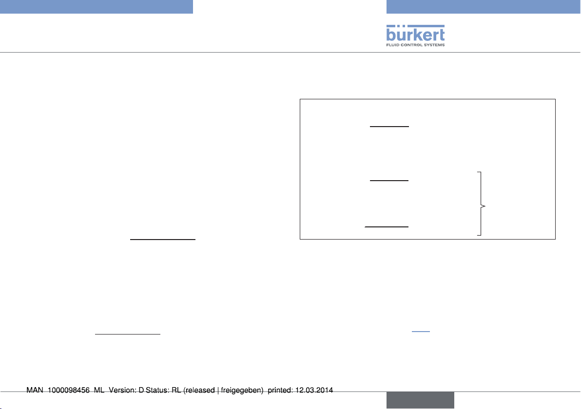
5 SYSTEM DESCRIPTION
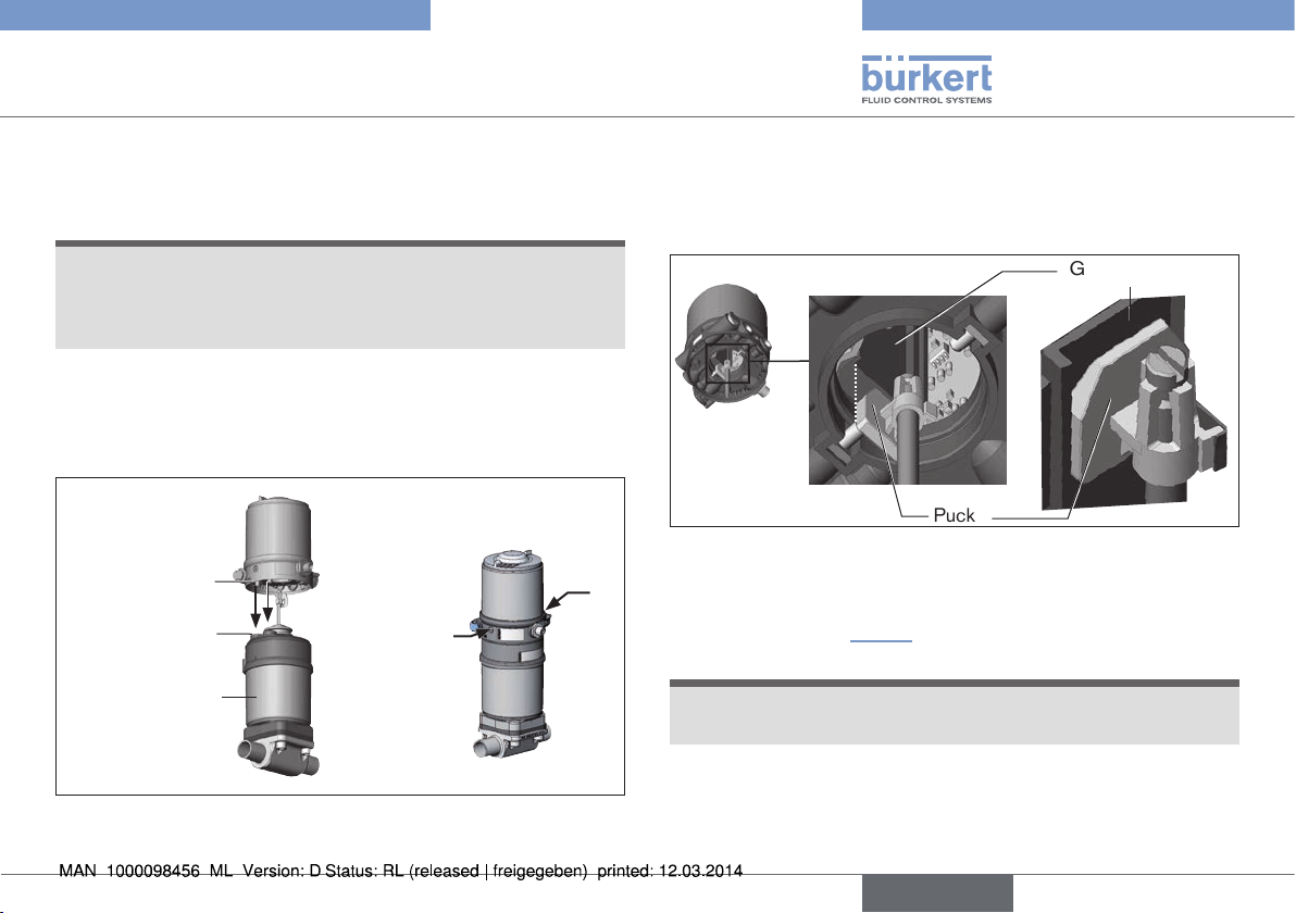
5.1 Structure and function
Control head
Actuator
Process valve
Valve body
Fig. 1: Structure
The control head Type 8691 can control single or double-acting
process valves and has been optimized for the integrated modular fitting
of series 21xx process valves (Element) . Various expansion stages are
possible thanks to the modular design.
For installation on the 20xx series (Classic) there is a special model
which is described in chapter “5.3”.
The valve position is recorded via a contactless, analog sensor element
which automatically detects and saves the valve end positions by means
of the teach function during start-up.
english
7
Page 8
Type 8691
System description
Apart from the electrical position feedback, the status of the device
is optically displayed on the control head itself by a colored highpower LED.
Option: Communication possible via AS-Interface or DeviceNet.
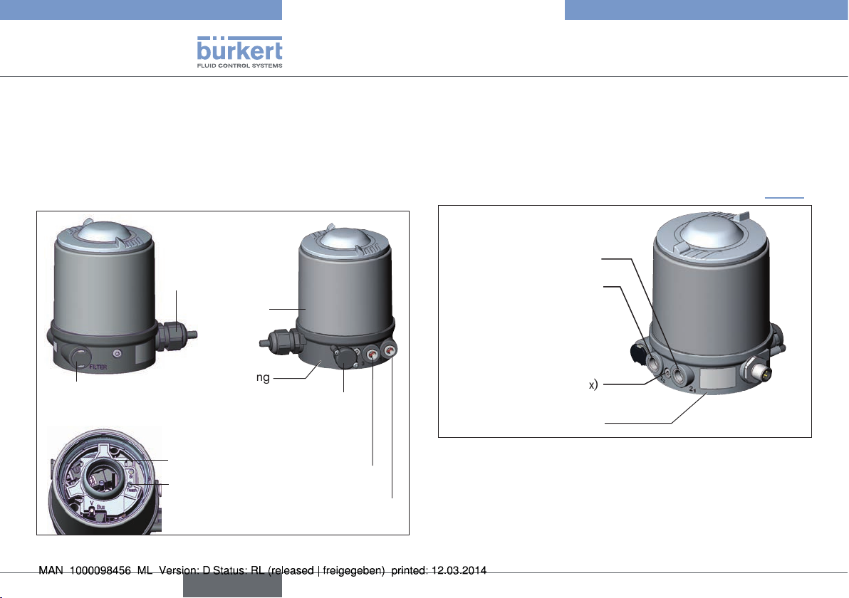
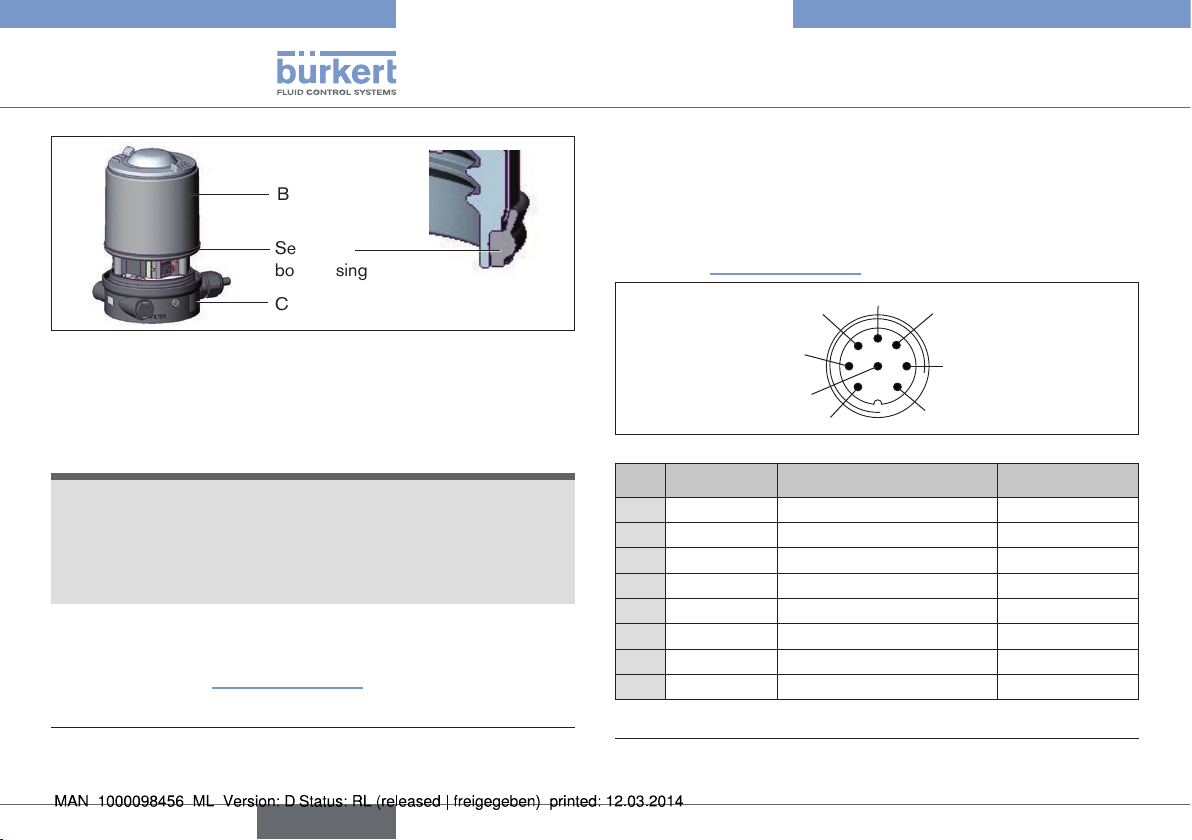
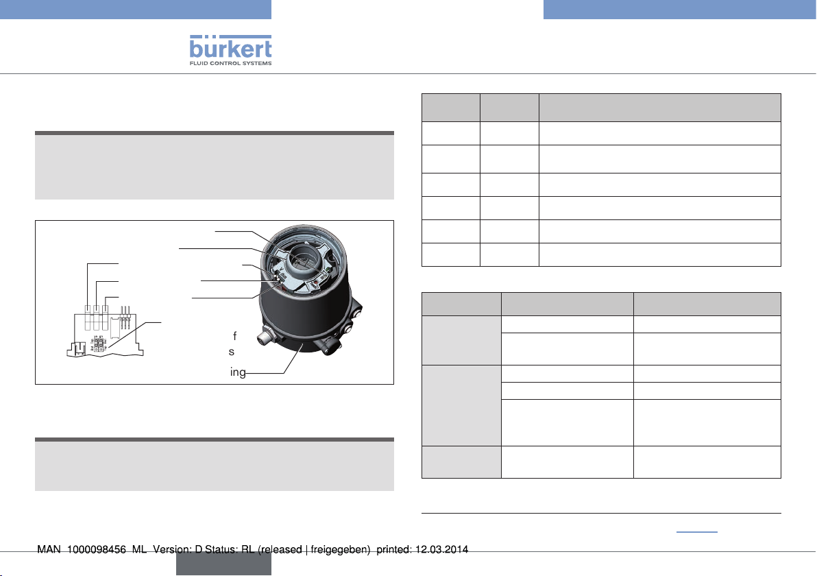
5.2 Control head for integrated
installation on the 21xx series
Electrical connection
Cable gland
M16 x 1.5 or
Circular plug-in
connector M12 x 1
Body casing
Air intake filter
View without transparent cap
Fig. 2: Structure for process valves belonging to the 21xx series
Connection housing
Pressure limiting valve
(for protection against too
high internal pressure in
Top LEDs
Teach function
case of error)
Exhaust air port
(label: 3)
Pilot air port
(label: 1)
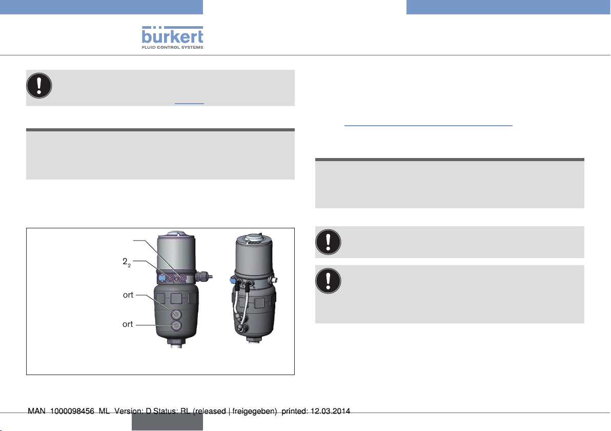
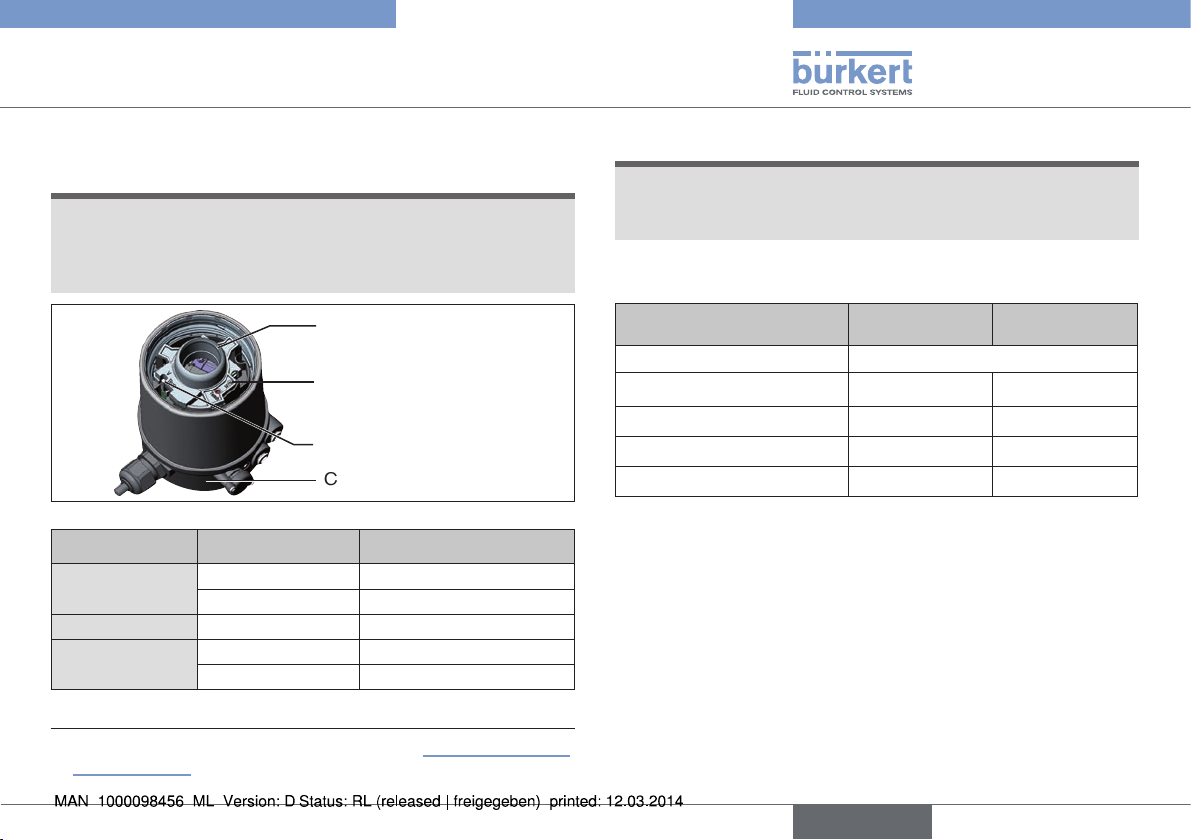
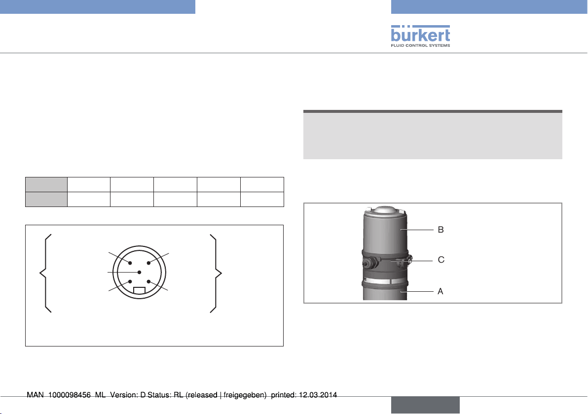
5.3 Model for control of process valves
belonging to the 20xx series
A special model enables the control head Type 8691 to be attached
to process valves belonging to the 20xx series.
This model features has a different connection housing so that the pilot
air ports can be connected to the outside of the actuator (see “Fig. 3”).
Pilot air outlet 2
Pilot air outlet 2
Fastening screws (2 x)
Connection housing
Fig. 3: Structure for process valves belonging to the 20xx series
1
2
8
english
Page 9
Type 8691
Technical data
6 TECHNICAL DATA
6.1 Conformity
In accordance with the EC Declaration of conformity, the control head
Type 8691 is compliant with the EC Directives.
6.2 Standards
The applied standards on the basis of which compliance with the EC
Directives is confirmed are listed in the EC type examination certificate
and/or the EC Declaration of Conformity.
6.3 Operating conditions
WARNING!
Solar radiation and temperature fluctuations may cause malfunctions or leaks.
▶ If the device is used outdoors, do not expose it unprotected to
the weather conditions.
▶ Ensure that the permitted ambient temperature does not exceed
the maximum value or drop below the minimum value.
Ambient temperature see type label
Degree of protection IP65 / IP67 according to EN 60529
(only if cables, plugs and sockets have
been connected correctly
and in compliance with the exhaust
air concept in chapter “8 Pneumatic
installation”).
6.4 Mechanical data
Dimensions see data sheet
Housing material exterior: PPS, PC, VA
Sealing material exterior: EPDM
interior: NBR
Stroke range of valve spindle: 2 – 28 mm
2 – 47 mm
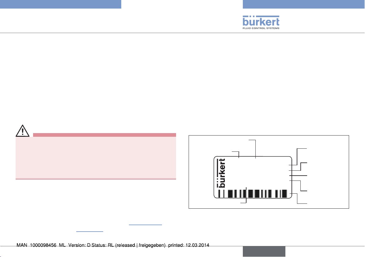
6.5 Type label
Example:
Supply voltage / Control
Typ
8691 AS-i 62SI
single act Pilot 3,0
Pmax 7bar
Tamb 0°C - +55°C
Ser.-Nr. 001000
00179024
D-74653 Ingelfingen
Identification number
Fig. 4: Type label (example)
CE
W14UN
Control function
- Pilot valve
Max. operating
pressure
Max. ambient
temperature
Serial number CE mark
Bar-code
english
9
Page 10
Type 8691
Technical data
6.6 Pneumatic data
Control medium neutral gases, air
Quality classes in accordance with DIN ISO 8573-1
Dust content Class 5 max. particle size 40 µm,
max. particle density 10 mg/m³
Water content Class 3 max. pressure dew point
- 20 °C or min. 10 °C below the
lowest operating temperature
Oil content Class 5 max. 25 mg/m³
Temperature range
control medium -10 – +50 °C
Pressure range
control medium 3 – 7 bar
Air output of pilot valve 250 l
Connections Plug-in hose connector ∅ 6 mm / 1/4“
/ min
N
(for aeration and deaeration)
(QNn - value according to definition for
pressure drop from 7 to 6 bar absolute)
Socket connection G 1/8
6.7 Electrical data
6.7.1 Electrical data without bus control
24 V DC
Connections Cable gland M16 x 1.5, wrench size 22
(clamping area 5 – 10 mm)
with screw-type terminals for cable crosssections 0.14 – 1.5 mm²
Circular plug-in connector
(M12 x 1, 8-pole)
Pilot valve
Supply voltage 24 V DC ± 10%
max. residual ripple 10 %
Power input max. 1 W
Output max. 100 mA per output
Display max. 20 mA per illustrated illuminated
display (LED)
10
english
Page 11

Type 8691
Technical data
6.7.2 Electrical data with AS-Interface bus
control
Connections Circular plug-in connector
(M12 x 1, 4-pole)
Supply voltage 29.5 V – 31.6 V DC
(according to specification)
Outputs
Max. switching capacity 1 W via AS-Interface
Watchdog function integrated
Devices without external supply voltage
Max. power consumption 120 mA
Power consumption input during
normal operation
(after current reduction;
valve + 1 end position reached) 90 mA
Devices with external supply voltage
External supply voltage 24 V ± 10 %
The power supply unit must include a secure disconnection in
accordance with IEC 364-4-41 (PELV or SELV)
Max. power consumption 55 mA (after current reduction
≤ 30 mA)
Max. power consumption
from AS-Interface 55 mA
6.7.3 Electrical data with DeviceNet bus
control
Connections Circular plug-in connector
(M12 x 1, 5-pole)
Supply voltage 11 V – 25 V
Max. power consumption < 80 mA
Output
Pull-in current current ≤ 50 mA
Holding current ≤ 30 mA
english
11
Page 12
Type 8691
Installation
7 INSTALLATION
Only for control head without pre-assembled process valve.
7.1 Safety instructions
DANGER!
Risk of injury from high pressure in the equipment/device.
▶ Before working on equipment or device, switch off the pressure
and deaerate/drain lines.
Risk of electric shock.
▶ Before working on equipment or device, switch off the power
supply and secure to prevent reactivation.
▶ Observe applicable accident prevention and safety regulations
for electrical equipment.
WARNING!
Risk of injury from improper installation.
▶ Installation may be carried out by authorized technicians only
and with the appropriate tools.
Risk of injury from unintentional activation of the system and
an uncontrolled restart.
▶ Secure system from unintentional activation.
▶ Following assembly, ensure a controlled restart.
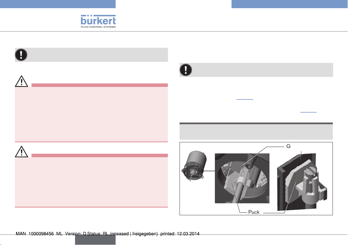
7.2 Installation of the control head on
process valves of series 21xx
Procedure:
When the control head is being installed, the collets of the
pilot air ports must not be fitted to the actuator.
→ Align the puck and the control head until
1. the puck can be inserted into the guide rail of the
control head (see “Fig. 5”) and
2. the connection pieces of the control head can be inserted
into the pilot air ports of the actuator (see also “Fig. 6”).
NOTE!
Damaged printed circuit board or malfunction.
▶ Ensure that the puck is situated flat on the guide rail.
Guide rail
Puck
Fig. 5: Aligning the puck
12
english
Page 13
Type 8691
Installation
→ Push the control head, without turning it, onto the actuator until
no gap is visible on the form seal.
NOTE!
Too high torque when screwing in the fastening screw does
not ensure degree of protection IP65 / IP67.
▶ The fastening screws may be tightened to a maximum torque of
0.5 Nm only.
→ Attach the control head to the actuator using the two side fas-
tening screws. In doing so, tighten the screws only hand-tight
(maximum torque: 0.5 Nm).
Connection
pieces
Pilot air ports
Actuator
Fig. 6: Installation of control head, 21xx series
Fastening
screws
max. 0.5 Nm
7.3 Installation of the control head on
process valves of series 20xx
Procedure:
Guide rail
Puck
Fig. 7: Aligning the puck
→ Push the control head onto the actuator. The puck must be
aligned in such a way that it is inserted into the guide rail of the
control head (see “Fig. 7”).
NOTE!
Damaged printed circuit board or malfunction.
▶ Ensure that the puck is situated flat on the guide rail.
→ Press the control head all the way down as far as the actuator
and turn it into the required position.
english
13
Page 14
Type 8691
Installation
Ensure that the pneumatic connections of the control head
and those of the valve actuator are situated preferably vertically one above the other (see “Fig. 8”).
NOTE!
Too high torque when screwing in the fastening screw does
not ensure degree of protection IP65 / IP67.
▶ The fastening screws may be tightened to a maximum torque of
0.5 Nm only.
→ Attach the control head to the actuator using the two side fas-
tening screws. In doing so, tighten the fastening screws handtight only (maximum torque: 0.5 Nm).
Pilot air outlet 2
Pilot air outlet 2
Upper pilot air port
Lower pilot air port
Fig. 8: Installing the pneumatic connection, 20xx series
1
2
Example
∅ 80, CFA
→ Screw the plug-in hose connectors onto the control head and
the actuator.
→ Using the hoses supplied in the accessory kit, make the pneu-
matic connection between the control head and actuator with
the “Tab. 1: Pneumatic connection to actuator”.
NOTE!
Damage or malfunction due to ingress of dirt and moisture.
▶ To comply with degree of protection IP65 / IP67, connect the
pilot air outlet (only for CFA or CFB) which is not required to the
free pilot air port of the actuator or seal with a plug.
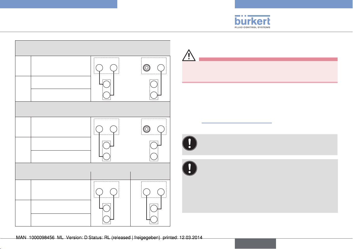
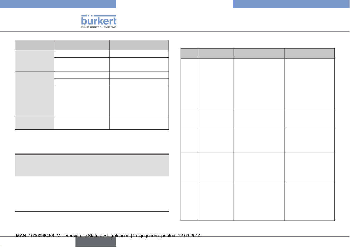
“In rest position” means that the pilot valves of the control head
Type 8691 are isolated or not actuated.
If the ambient air is humid, a hose can be connected between
pilot air outlet 22 of the control head and the unconnected
pilot air port of the actuator for control function A or control
function B. As a result, the spring chamber of the actuator is
supplied with dry air from the vent duct of the control head.
14
english
Page 15
Type 8691
Pneumatic installation
Control function A (CFA)
Process valve closed in rest position (by spring force)
Pilot air outlet
Control
head
Upper pilot air port
Lower pilot air port
Actuator
222
1
222
or
Control function B (CFB)
Process valve open in rest position (by spring force)
Pilot air outlet
Control
head
Upper pilot air port
Lower pilot air port
Actuator
222
1
222
or
Control function I (CFI)
Process valve in rest position closed open
Pilot air outlet
Control
head
222
1
222
Upper pilot air port
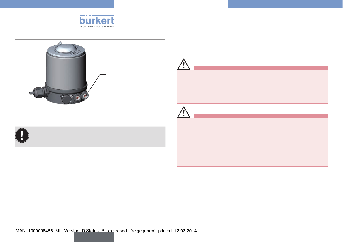
8 PNEUMATIC INSTALLATION
DANGER!
1
Risk of injury from high pressure in the equipment/device.
▶ Before working on equipment or device, switch off the pressure
and deaerate/drain lines.
Procedure:
→ Connect the control medium to the pilot air port (1)
(3 – 7 bar; instrument air, free of oil, water and dust).
→ Attach the exhaust airline or a silencer to the exhaust air port (3)
1
1
(see “Fig. 9: Pneumatic connection”).
Keep the adjacent supply pressure always at least 0.5 –
1 bar above the pressure which is required to move the
actuator to its end position.
Important information for the problem-free functioning of
the device:
▶ The installation must not cause back pressure to build up.
▶ Select a hose for the connection with an adequate
cross-section.
▶ The exhaust air line must be designed in such a way that
no water or other liquid can get into the device through the
exhaust air port.
Lower pilot air port
Actuator
Tab. 1: Pneumatic connection to actuator
english
15
Page 16
Type 8691
Electrical installation
9 ELECTRICAL INSTALLATION
9.1 Safety instructions
DANGER!
Pilot air port
(label: 1)
Exhaust air port
(label: 3)
Fig. 9: Pneumatic connection
Caution: (Exhaust air concept):
In compliance with degree of protection IP67, an exhaust air
line must be installed in the dry area.
16
english
Risk of electric shock.
▶ Before working on equipment or device, switch off the power
supply and secure to prevent reactivation.
▶ Observe applicable accident prevention and safety regulations
for electrical equipment.
WARNING!
Risk of injury from improper installation.
▶ Installation may be carried out by authorized technicians only
and with the appropriate tools.
Risk of injury from unintentional activation of the system and
an uncontrolled restart.
▶ Secure system from unintentional activation.
▶ Following installation, ensure a controlled restart.
Page 17
ye
gn
y
e
gn
o
p
p
Type 8691
Electrical installation
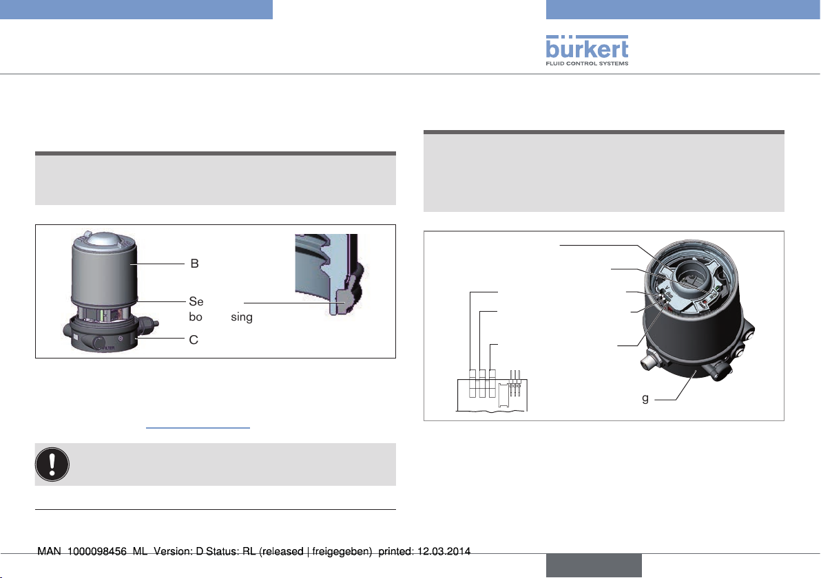
9.2 Electrical installation 24 V DC
9.2.1 Electrical installation with cable gland
NOTE!
Breakage of the pneumatic connection pieces due to rotational impact.
▶ When unscrewing and screwing in the body casing, do not hold
the actuator of the process valve but the connection housing.
→ Unscrew the body casing (stainless steel) in a counter-clockwise
direction.
Body casing
Connection housing
Actuator
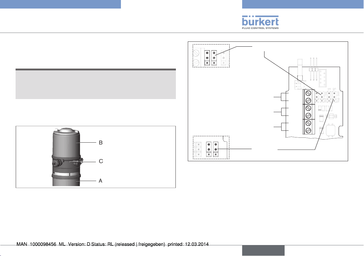
Fig. 10: Open control head
→ Push the cables through the cable gland.
→ Connect the wires.
Jumper: assignment p-n-p or n-p-n
To
IN 1 = Top (top)
IN 2 = Bot (bottom)
Screw terminals
end positions
Screw terminals
Supply 24 V DC
Screw terminals
Valve (control)
Bot
Top
Bot
Top
Fig. 11: Connection with cable gland
Jumper:
Color assignment of the Top LEDs
outlet (optional)
IN 1
IN 2
+
24 V
-
+
Valve
-
english
17
Page 18
Body casing
Seal
body casing
Connection housing
Fig. 12: Position of the seal in the body casing
→ Tighten union nut on the cable gland (torque approx. 1.5 Nm).
→ Check that the seal is correctly positioned in the body casing.
→ Close the device (assembly tool: 674077
NOTE!
Damage or malfunction due to penetration of dirt and humidity.
To ensure degree of protection IP65 / IP67:
▶ Tighten the union nut on the cable gland according to the cable
size or dummy plugs used. (ca. 1,5 Nm).
▶ Screw the body casing in all the way.
The teach function can now be used to automatically determine
and read in the end positions of the valve (description of the teach
function see chapter “10 Teach function”).
1)
).
Type 8691
Electrical installation
9.2.2 Electrical installation 24 V DC with
circular plug-in connector
→ Connect the control head according to the table.
The teach function can now be used to automatically determine and
read in the end positions of the valve (description of the teach function
see chapter “10 Teach function”).
6
7
8
Fig. 13: Circular plug M12 x 1, 8-pole
Pin Wire color2)Designation Configuration
white Limit switch top IN 1 (=Top)
1
brown Limit switch bottom IN 2 (=Bot)
2
green Supply voltage GND
3
yellow Supply voltage + 24 V DC
4
grey Valve control unit + Valve +
5
pink Valve control unit - Valve -
6
7
8
Tab. 2: Connection with circular plug-in connector
- not used
- not used
5
4
3
1
2
1) The assembly tool (674077) is available from your Bürkert sales office.
18
english
2) The indicated colors refer to the connecting cable available as an
accessory (919061).
Page 19
Type 8691
Electrical installation
9.3 Display elements 24 V DC
NOTE!
Breakage of the pneumatic connection pieces due to rotational impact.
▶ When unscrewing and screwing in the transparent cap, do not
hold the actuator of the process valve but the connection housing.
Top LEDs
Status LED (yellow)
LED pilot valve (yellow)
Connection housing
Fig. 14: Display elements 24 V DC
LED Color
Top LEDs
3)
LED Pilot valve
Status LED
Tab. 3: Display elements 24 V DC
is lit green End postion bottom
is lit yellow End postion top
is lit yellow
Pilot valve is actuated
flashing yellow Teach function is running
flickers yellow Puck PCB not available
NOTE!
Damage or malfunction due to penetration of dirt and humidity.
▶ To observe degree of protection IP65 / IP67, screw the trans-
parent cap in all the way.
9.4 Programming data AS-Interface
AS-Interface
31 slaves
I/O configuration B hex (1 input, 2 outputs)
ID code F hex A hex
Extended ID code 1 F hex 7 hex
Extended ID code 2 F hex E hex
Profile S-B.F.F S-B.A.E
Tab. 4: Programming data
AS-Interface
62 slaves
3) Color setting ex works. Can be set via jumper (see “Fig. 11: Connection
with cable gland”).
english
19
Page 20
Type 8691
Electrical installation
9.5 Electrical installation AS-Interface
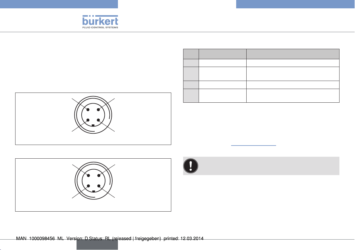
9.5.1 Connection with circular plug-in
connector M12 x 1, 4-pole, male
Connector views
The views show the image from the front looking at the pins, the
solder connections are behind them.
Pin 4:
NC
Pin 1:
Bus +
Fig. 15: Bus connection without external supply voltage
Pin 4:
24 V +
Pin 1:
Bus +
Fig. 16: Bus connection with external supply voltage (optional)
Pin 3:
Bus –
Pin 2:
NC
Pin 3:
Bus –
Pin 2:
GND
Bus connection without external / with external supply voltage
Pin Designation Configuration
Bus + AS-Interface bus line +
1
NC or GND
2
(optional)
Bus – AS-Interface bus line –
3
NC or 24 V +
4
(optional)
Tab. 5: Pin assignment of circular plug-in connector for AS-Interface
not used or external supply voltage –
(optional)
not used or external supply voltage +
(optional)
→ Connect the control head according to the table.
The teach function can now be used to automatically determine
and read in the end positions of the valve (description of the teach
function see chapter “10 Teach function”).
For the bus variant AS-Interface, the teach function can also
be started via the bus protocol.
20
english
Page 21
Type 8691
Electrical installation
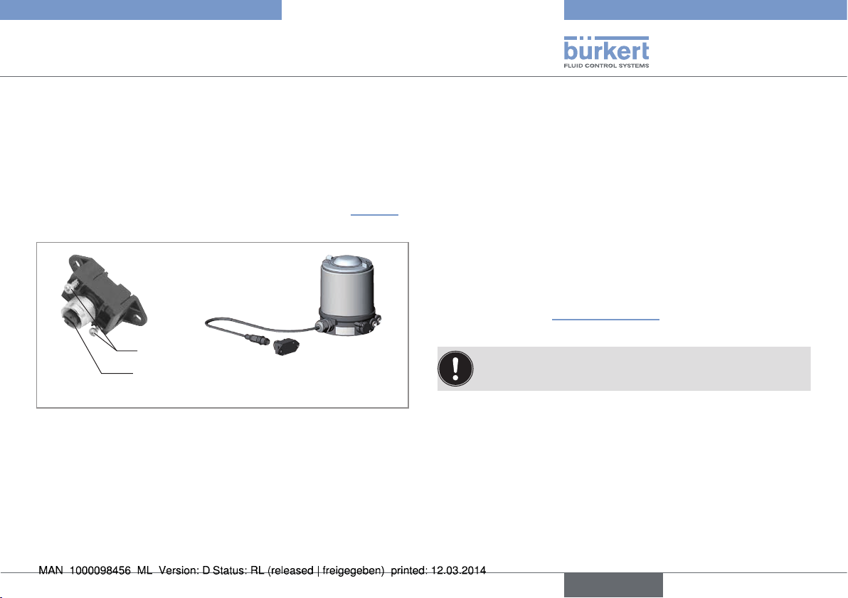
9.5.2 Connection with multi-pole cable and
ribbon cable terminal
As an alternative to the bus connection model with 4-pole circular
plug, there is the control head with multi-pole cable (M12 circular plug)
and ribbon cable terminal. The wiring diagram of the circular plug corresponds to the bus connection of the M12 4-pole circular plug and
can easily be connected to the ribbon cable terminal (see “Fig. 17”).
Screws
M12 plug-in connector
branch circuit
Fig. 17: Control head 8691 with multi-pole cable and ribbon cable terminal
Handling the ribbon cable terminal
The multi-pole cable features a ribbon cable terminal - with M12 plug-in
connector branch circuit - for AS-Interface cable harness. The ribbon
cable terminal contacts the AS-Interface cable harness by means of
penetration technology which allows installation by “clipping in” the ASInterface cable harness without cutting and without removing insulation.
Procedure:
→ Open the ribbon cable terminal
(loosen screws and remove cover)
→ Insert cable harness conclusively
→ Close ribbon cable terminal again
→ Tighten screws
Slightly undo thread-forming screws
(approx. 3/4 turn to the left) and position them on the existing
tapped bore and screw in.
The teach function can now be used to automatically determine
and read in the end positions of the valve (description of the teach
function see chapter “10 Teach function”).
For the bus variant AS-Interface, the teach function can also
be started via the bus protocol.
english
21
Page 22
Type 8691
Electrical installation
9.6 Display elements AS-Interface
NOTE!
Breakage of the pneumatic connection pieces due to rotational impact.
▶ When unscrewing and screwing in the transparent cap, do not
hold the actuator of the process valve but the connection housing.
Status LED yellow
Top LEDs
Pilot valve LED yellow
Bus LED green
Bus LED red
Jumper: Color
assignment of
the Top LEDs
Connection housing
Fig. 18: Display elements AS-Interface
NOTE!
Damage or malfunction due to penetration of dirt and humidity.
▶ To observe degree of protection IP65 / IP67, screw the trans-
parent cap in all the way.
Bus LED
(green)
Bus LED
(red)
off off POWER OFF
off on
No data traffic (expired Watch Dog at slave
address does not equal 0)
on off OK
flashing on Slave address equals 0
off flashing Sensor supply overloaded or external reset
flashing flashing Teach function error (Periphery error)
Tab. 6: Display elements bus status
LED Color
Status LED flashing yellow Teach function is running
flickers yellow Puck PCB not available
4)
Top LEDs
is lit green End postion bottom
is lit yellow End postion top
flashing red
alternately with the
green or yellow
LED
Pilot valve
Tab. 7: Display elements AS-Interface
is lit yellow Pilot valve is actuated
no data traffic or
teach function error
22
4) Color setting ex works. Can be set via jumper (see “Fig. 18”).
english
Page 23
Type 8691
Electrical installation
9.7 Electrical installation DeviceNet
9.7.1 Bus connection (circular connector
M12 x 1, 5-pole, male)
The control head features a 5-pole micro-style circular connector.
The following configuration conforms to the DeviceNet specification.
→ Connect the control head according to the table.
Pin
Signal
Tab. 8: Pin assignment circular plug-in connector DeviceNet
Data lines
Fig. 19: View of plug from the front onto the pins, the soldered connections
1 2 3 4 5
Shielding V + V – CAN_H CAN_L
Pin 4: CAN_H
white
Pin 5: CAN_L
blue
Pin 1: Drain
(Shield)
are behind
Pin 3: V–
black
Pin 2: V+
red
max. power 3 W,
if valve is switched
Supply voltage
11 – 25 V DC
9.7.2 Configuring the control head
Setting the DIP switches
NOTE!
Breakage of the pneumatic connection pieces due to rotational impact.
▶ When unscrewing and screwing in the body casing, do not hold
the actuator of the process valve but the connection housing.
→ Unscrew the body casing (stainless steel) in a counter-clockwise
direction.
Body casing
Connection housing
Actuator
Fig. 20: Open control head
english
23
Page 24
Type 8691
Electrical installation
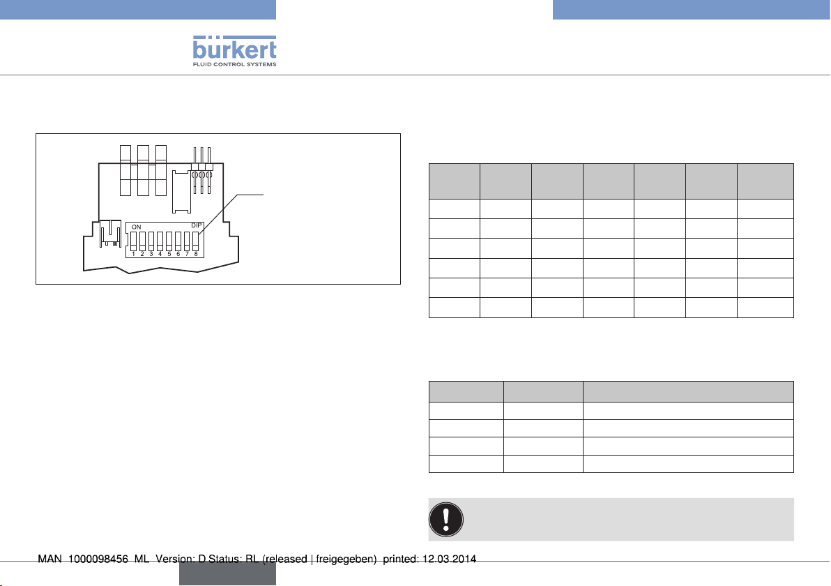
→ Set the DIP switches according to the following tables.
DIP switches
for bus address
and baudrate
Fig. 21: DIP switches DeviceNet
8 DIP switches are available for configuration:
• DIP switches 1 to 6 for the DeviceNet address
• DIP switches 7 to 8 for the baudrate
Settings of the DeviceNet address
MAC ID – Medium Access Control Identifier:
[DIP 1=off=0 / DIP 1=on=1 /
MAC ID=DIP 1*2
DIP 1
[20=1]
DIP 2
[21=2]
0
+DIP 2*21+...+DIP 6*25]
DIP 3
[22=4]
DIP 4
[23=8]
DIP 5
[24=16]
DIP 6
[25=32]
off off off off off off 0
on
off
...
off
off off off off off 1
on
off off off off 2
... ... ... ... ... ...
on on on on on
on on on on on on
Tab. 9: Settings of the DeviceNet address
Setting the baudrate
Adjusting the control head to the baudrate of the network.
DIP 7 DIP 8 Baudrate
off off 125 kBaud
on off 250 kBaud
off on 500 kBaud
on on not permitted
Tab. 10: Setting the baudrate
MAC ID
62
63
24
If the settings are changed by actuating the DIP switches,
this change will not take effect until the device is restarted.
english
Page 25
Type 8691
Electrical installation
→ Check that the seal is correctly positioned in the body casing.
→ Close the device (assembly tool: 674077
NOTE!
Damage or malfunction due to penetration of dirt and humidity.
▶ To observe degree of protection IP65 / IP67, screw the body
casing in all the way.
Body casing
Seal
body casing
Connection housing
Fig. 22: Position of the seal in the body casing
The teach function can now be used to automatically determine
and read in the end positions of the valve (description of the teach
function see chapter “10 Teach function”).
For the bus variant DeviceNet, the teach function can also
be started via the bus protocol.
5) The assembly tool (674077) is available from your Bürkert sales office.
5)
).
9.8 Display elements DeviceNet
NOTE!
Breakage of the pneumatic connection pieces due to rotational impact.
▶ When unscrewing and screwing in the transparent cap, do
not hold the actuator of the process valve but the connection
housing.
Top LEDs
Status LED (yellow)
Pilot valve LED (yellow)
Device status LED (two-
coloured: red/green)
Bus status LED (two-
coloured: red/green)
Connection housing
Fig. 23: LED display, DeviceNet
The device status of the control head (transparent cap) is displayed
optically by colored high-power LEDs (Top LEDs). The assignment of
the green and yellow Top LEDs to the end position can be changed via
Explicit Messages (attribute address: class 150, instance 1, attribute 9).
english
25
Page 26
Type 8691
Electrical installation
LED Color
Status LED flashing yellow Teach function is running
flickers yellow Puck PCB not available
6)
Top LEDs
is lit green End postion bottom
is lit yellow End postion top
• Online, without con-
flashing red
alternately with the
green or yellow
nection to the Master
• Connection time-out
• Critical error
LED
Pilot valve
Tab. 11: Display elements DeviceNet
is lit yellow Pilot valve is actuated
NOTE!
Damage or malfunction due to penetration of dirt and humidity.
▶ To observe degree of protection IP65 / IP67, screw the trans-
parent cap in all the way.
6) Color setting ex works.
Status of the bus status LED
LED Device status Explanation Troubleshooting
Device is not supplied
with voltage
No power
Off
Green
Flashes
green
Flashes
red
Red Critical fault
Tab. 12: Status of the bus status LED
supply /
not online
Online, connection to
master exists
Online, without
connection to
master
Connection
time-Out
Device has still not
ended Duplicate MAC
ID Test (test lasts
approx. 2 sec)
Device cannot end
Duplicate MAC ID Test.
Normal operating status
with established connection to the master
Normal operating status
without established
connection to the
master
One or more I/O connections are in TimeOut state
Another device with the
same MAC ID address
is in the circuit
No bus connection
due to communication
problems
Connect other devices,
if the device is the only
network subscriber,
Replace device
Check baud rate
Check bus connection
New connection establishment by master to
ensure that the I/O
data is transmitted
cyclically.
Check baud rate
If required, replace
device
26
english
Page 27
Type 8691
Teach function
Status of the device status LED
LED Device status Explanation
Off No supply Device is not supplied with voltage
Green Device is working Normal operating status
Tab. 13: Status of the device status LED
10 TEACH FUNCTION
The teach function can be used to automatically determine and read
in the end positions of the valve.
For the bus variant AS-Interface and DeviceNet, the teach
function can also be started via the bus protocol.
10.1 Starting the teach function
Necessary requirements:
Before you can actuate the teach function, you must
• mount the control head on the actuator,
• connect the supply voltage,
• connect the compressed-air supply,
• AS-Interface: pilot valve OFF (D0 = 0),
• the DeviceNet must be connected to the Master (bus LED
must be lit green).
english
27
Page 28

Type 8691
Teach function
Transparent cap
Body casing
Connection housing
Actuator
Fig. 24: Open control head
NOTE!
Breakage of the pneumatic connection pieces due to rotational impact.
▶ When unscrewing and screwing in the transparent cap, do
not hold the actuator of the process valve but the connection
housing.
→ Open the control head: turning the transparent cap
anti-clockwise.
→ The key in recess for actuating the teach function keep pressed
for approximately 5 seconds.
→ Only for control heads without pilot valve:
When yellow pilot valve LED is lit, move actuator to upper end
position.
When yellow pilot valve LED goes out again, move actuator to
lower end position.
NOTE!
Damage or malfunction due to penetration of dirt and humidity.
▶ To observe degree of protection IP65 / IP67, screw the trans-
parent cap in all the way.
→ Close the device (assembly tool: 674077
Pilot valve LED (yellow)
Status LED: flashes yellow
when teach function is running
Key in recess for actuating the
teach function (keep pressed
for approximately 5 seconds
Fig. 25: Teach function
Chronological description of the teach function:
• the bottom position is read in internally
• the pilot valve switches
the top position
• the top position is read in internally
• the pilot valve is turned off
home position.
Important: When the teach function is activated the actuator
cannot be actuated via the AS-Interface and DeviceNet
communication.
7) The assembly tool (674077) is available from your Bürkert sales office.
the actuator moves automatically to
the actuator moves back to the
7)
).
28
english
Page 29

Type 8691
Safety positions
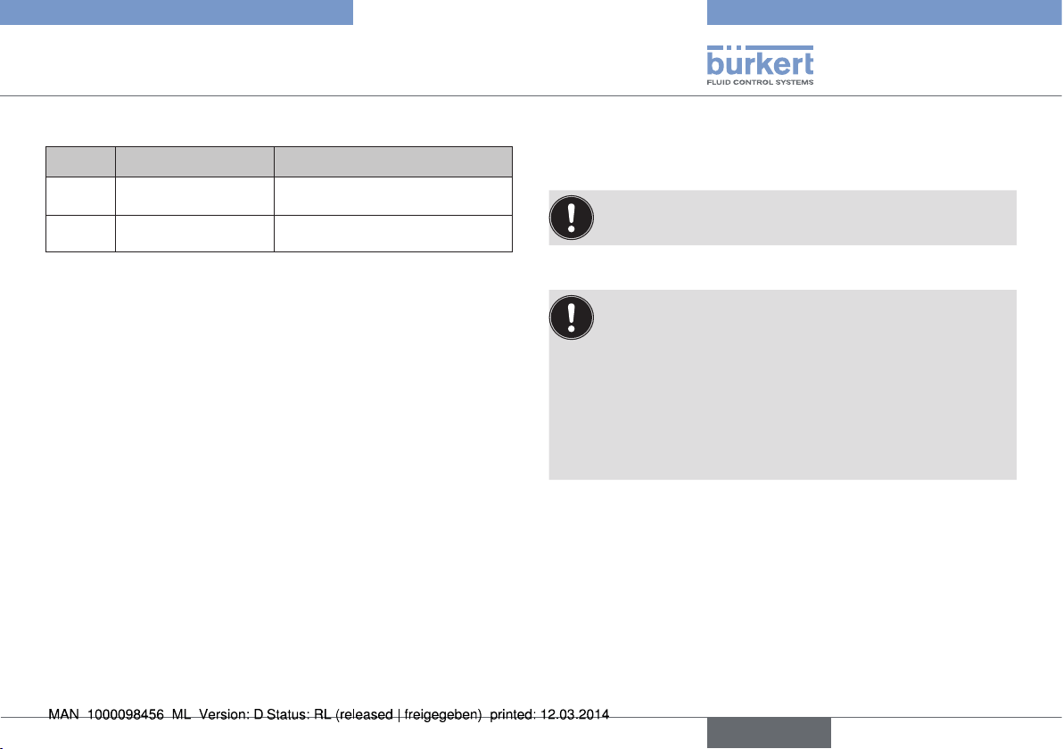
11 SAFETY POSITIONS
Safety positions after failure
Actuator system Designation
single-acting
up
down
up
down
up
down
Tab. 14: Safety positions
Control
function A
single-acting
Control
function B
double-acting
Control
function I
of the auxiliary power
electrical pneumatic
down down
up up
down not defined
12 ACCESSORIES
Designation Order no.
Connection cable M12 x 1, 8-pole 919061
Assembly tool 674077
Tab. 15: Accessories
english
29
Page 30

13 PACKAGING, TRANSPORT,
STORAGE
NOTE!
Transport damages.
Inadequately protected equipment may be damaged during transport.
▶ During transportation protect the device against wet and dirt in
shock-resistant packaging.
▶ Avoid exceeding or dropping below the permitted storage
temperature.
Incorrect storage may damage the device.
▶ Store the device in a dry and dust-free location.
▶ Storage temperature -20 – +65 °C.
Damage to the environment caused by device components
contaminated with media.
▶ Dispose of the device and packaging in an environmentally friendly
manner.
▶ Observe applicable regulations on disposal and the environment.
Type 8691
Packaging, Transport, Storage
30
english
Page 31

Typ 8691
Inhaltsverzeichnis
1 DER QUICKSTART .................................................................................... 32
1.1 Begriffsdefinition / Abkürzung ..............................................32
1.2 Darstellungsmittel ....................................................................32
2 BESTIMMUNGSGEMÄSSE VERWENDUNG................................33
2.1 Beschränkungen ......................................................................33
3 GRUNDLEGENDE SICHERHEITSHINWEISE .............................. 33
4 ALLGEMEINE HINWEISE ....................................................................... 35
4.1 Kontaktadresse ........................................................................35
4.2 Gewährleistung ........................................................................35
4.3 Informationen im Internet .......................................................35
5 SYSTEMBESCHREIBUNG .................................................................... 35
5.1 Aufbau und Funktion ...............................................................35
5.2 Steuerkopf für den integrierten Anbau an 21xx ................36
5.3 Variante zur Ansteuerung von Prozessventilen der
Reihe 20xx.................................................................................36
6 TECHNISCHE DATEN ............................................................................. 37
6.1 Konformität ................................................................................37
6.2 Normen ......................................................................................37
6.3 Betriebsbedingungen .............................................................37
6.4 Mechanische Daten ................................................................37
6.5 Typschild ..................................................................................37
6.6 Pneumatische Daten ..............................................................38
6.7 Elektrische Daten ....................................................................38
7 MONTAGE .....................................................................................................40
7.1 Sicherheitshinweise ................................................................40
7.2 Montage Steuerkopf an Prozessventile der Reihe
21xx ............................................................................................40
7.3 Montage Steuerkopf an Prozessventile der Reihe
20xx ............................................................................................41
8 PNEUMATISCHE INSTALLATION ...................................................... 43
9 ELEKTRISCHE INSTALLATION ...........................................................44
9.1 Sicherheitshinweise ................................................................44
9.2 Elektrische Installation 24 V DC ..........................................45
9.3 Anzeigeelemente 24 V DC ...................................................47
9.4 Programmierdaten AS-Interface ..........................................47
9.5 Elektrische Installation AS-Interface ...................................48
9.6 Anzeigeelemente AS-Interface.............................................50
9.7 Elektrische Installation DeviceNet .......................................51
9.8 Anzeigeelemente DeviceNet .................................................53
10 TEACHFUNKTION ..................................................................................... 55
10.1 Starten der Teachfunktion .....................................................55
11 SICHERHEITSSTELLUNGEN .............................................................. 57
12 ZUBEHÖR .....................................................................................................57
13 TRANSPORT, LAGERUNG, VERPACKUNG .................................. 58
deutsch
31
Page 32

Typ 8691
Der Quickstart
1 DER QUICKSTART
Der Quickstart beschreibt den gesamten Lebenszyklus des Geräts.
Bewahren Sie den Quickstart so auf, dass er für jeden Benutzer gut
zugänglich ist und jedem neuen Eigentümer des Geräts wieder zur
Verfügung steht.
Wichtige Informationen zur Sicherheit.
Lesen Sie den Quickstart sorgfältig durch. Beachten Sie vor allem
die Kapitel „Grundlegende Sicherheitshinweise“ und „Bestimmungsgemäße Verwendung“.
▶ Der Quickstart muss gelesen und verstanden werden.
Der Quickstart erläutert beispielhaft die Montage und Inbetriebnahme
des Geräts.
Die ausführliche Beschreibung des Geräts finden Sie in der Bedienungsanleitung für den Steuerkopf Typ 8691.
Die Bedienungsanleitung finden Sie auf der beigelegten CD
oder im Internet unter:
www.buerkert.de
1.1 Begriffsdefinition / Abkürzung
Der in dieser Anleitung verwendeten Begriff „Gerät“ steht immer für
den Steuerkopf Typ 8691.
Die in dieser Anleitung verwendete Abkürzung „Ex“ steht immer für
„explosionsgefährdet“.
1.2 Darstellungsmittel
In dieser Anleitung werden folgende Darstellungsmittel verwendet.
GEFAHR!
Warnt vor einer unmittelbaren Gefahr.
▶ Bei Nichtbeachtung sind Tod oder schwere Verletzungen die
Folge.
WARNUNG!
Warnt vor einer möglicherweise gefährlichen Situation.
▶ Bei Nichtbeachtung können schwere Verletzungen oder Tod die
Folge sein.
VORSICHT!
Warnt vor einer möglichen Gefährdung.
▶ Nichtbeachtung kann mittelschwere oder leichte Verletzungen
zur Folge haben.
HINWEIS!
Warnt vor Sachschäden.
Wichtige Tipps und Empfehlungen.
verweist auf Informationen in dieser Anleitung oder in
anderen Dokumentationen.
▶ markiert eine Anweisung zur Gefahrenvermeidung.
→ markiert einen Arbeitsschritt den Sie ausführen müssen.
32
deutsch
Page 33

Typ 8691
Bestimmungsgemäße Verwendung
2 BESTIMMUNGSGEMÄSSE
VERWENDUNG
Bei nicht bestimmungsgemäßem Verwendung des Steuerkopfs Typ 8691 können Gefahren für Personen, Anlagen in der
Umgebung und die Umwelt entstehen.
▶ Das Gerät ist für den Anbau an pneumatische Antriebe von Pro-
zessventilen zur Steuerung von Medien konzipiert.
▶ Gerät nicht der direkten Sonneneinstrahlung aussetzen.
▶ Für den Einsatz die in den Vertragsdokumenten und der Bedie-
nungsanleitung spezifizierten zulässigen Daten, Betriebs- und
Einsatzbedingungen beachten. Diese sind im Kapitel „6 Techni-
sche Daten“ beschrieben.
▶ Gerät nur in Verbindung mit von Bürkert empfohlenen bzw. zuge-
lassenen Fremdgeräten und -komponenten einsetzen.
▶ Angesichts der Vielzahl von Einsatz- und Verwendungsfällen,
muss vor dem Einbau geprüft und erforderlichenfalls getestet
werden, ob das Gerät für den konkreten Einsatzfall geeignet ist.
▶ Voraussetzungen für den sicheren und einwandfreien Betrieb
sind sachgemäßer Transport, sachgemäße Lagerung und Instal-
lation sowie sorgfältige Bedienung und Instandhaltung.
▶ Gerät nur bestimmungsgemäß verwenden.
2.1 Beschränkungen
Beachten Sie bei der Ausfuhr des Systems/Geräts gegebenenfalls
bestehende Beschränkungen.
3 GRUNDLEGENDE
SICHERHEITSHINWEISE
Diese Sicherheitshinweise berücksichtigen keine
• Zufälligkeiten und Ereignisse, die bei Montage, Betrieb und
Wartung der Geräte auftreten können.
• ortsbezogenen Sicherheitsbestimmungen, für deren Einhaltung,
auch in Bezug auf das Montagepersonal, der Betreiber verantwortlich ist.
GEFAHR!
Verletzungsgefahr durch hohen Druck in Anlage/Gerät.
▶ Vor Arbeiten an Anlage oder Gerät, den Druck abschalten und
Leitungen entlüften/entleeren.
Gefahr durch Stromschlag.
▶ Vor Arbeiten an Anlage oder Gerät, die Spannung abschalten und
vor Wiedereinschalten sichern.
▶ Die geltenden Unfallverhütungs- und Sicherheitsbestimmungen
für elektrische Geräte beachten.
deutsch
33
Page 34

Typ 8691
Grundlegende Sicherheitshinweise
Allgemeine Gefahrensituationen.
Zum Schutz vor Verletzungen ist zu beachten:
▶ Im explosionsgefährdeten Bereich darf der Steuerkopf Typ 8691
nur entsprechend der Spezifikation auf dem separaten Klebeschild
für die Zulassung eingesetzt werden. Für den Einsatz muss die
dem Gerät beiliegende Zusatzanleitung mit Sicherheitshinweisen
für den Ex-Bereich beachtet werden.
▶ Geräte ohne separates Klebeschild für die Zulassung dürfen nicht
im explosionsgefährdeten Bereich eingesetzt werden.
▶ Dass die Anlage nicht unbeabsichtigt betätigt werden kann.
▶ Installations- und Instandhaltungsarbeiten dürfen nur von auto-
risiertem Fachpersonal mit geeignetem Werkzeug ausgeführt
werden.
▶ Nach einer Unterbrechung der elektrischen oder pneumatischen
Versorgung ist ein definierter oder kontrollierter Wiederanlauf des
Prozesses zu gewährleisten.
▶ Das Gerät darf nur in einwandfreiem Zustand und unter Beachtung
der Bedienungsanleitung betrieben werden.
▶ Für die Einsatzplanung und den Betrieb des Geräts müssen die
allgemeinen Regeln der Technik eingehalten werden.
Zum Schutz vor Sachschäden am Gerät ist zu beachten:
▶ In den Steuerluftanschluss keine aggressiven oder brennbaren
Medien einspeisen.
▶ In den Steuerluftanschluss keine Flüssigkeiten einspeisen.
▶ Beim Abschrauben und Einschrauben des Gehäusemantels oder
der Klarsichthaube nicht am Antrieb des Prozessventils, sondern
am Anschlussgehäuse des Typs 8691 gegenhalten.
▶ Gehäuse nicht mechanisch belasten (z. B. durch Ablage von
Gegenständen oder als Trittstufe).
▶ Keine äußerlichen Veränderungen an den Gerätegehäusen vor-
nehmen. Gehäuseteile und Schrauben nicht lackieren.
34
deutsch
Page 35

Typ 8691
Allgemeine Hinweise
4 ALLGEMEINE HINWEISE
4.1 Kontaktadresse
Deutschland
Bürkert Fluid Control Systems
Sales Center
Chr.-Bürkert-Str. 13-17
D-74653 Ingelfingen
Tel. + 49 (0) 7940 - 10 91 111
Fax + 49 (0) 7940 - 10 91 448
E-mail: info@de.buerkert.com
International
Die Kontaktadressen finden Sie auf den letzten Seiten der
gedruckten Bedienungsanleitung.
Außerdem im Internet unter:
www.burkert.com
4.2 Gewährleistung
Voraussetzung für die Gewährleistung ist der bestimmungsgemäße
Gebrauch des Steuerkopfs Typ 8691 unter Beachtung der spezifizierten Einsatzbedingungen.
4.3 Informationen im Internet
Bedienungsanleitungen und Datenblätter zum Typ 8691 finden Sie
im Internet unter:
www.buerkert.de
5 SYSTEMBESCHREIBUNG
5.1 Aufbau und Funktion
Steuerkopf
Pneumatischer
Antrieb
Prozessventil
Ventilgehäuse
Bild 1: Aufbau
Der Steuerkopf Typ 8691 kann einfach- oder doppeltwirkende Prozessventile ansteuern und ist für den integrierten, modularen Anbau
an Prozessventile der Reihe 21xx optimiert. Der modulare Aufbau
ermöglicht verschiedene Ausbaustufen.
Für den Anbau an die Reihe 20xx gibt es eine spezielle Variante, die
in Kapitel „5.3“ beschrieben ist.
Die Erfassung der Ventilstellung erfolgt über ein kontaktloses, analoges
Sensorelement, welches bei der Inbetriebnahme die Ventilendstellungen automatisch mittels Teachfunktion erkennt und speichert.
deutsch
35
Page 36

Typ 8691
Systembeschreibung
Neben der elektrischen Stellungsrückmeldung wird der Gerätestatus
am Steuerkopf selbst optisch durch farbige Hochleistungs-LEDs (Top
LEDs) dargestellt.
Option: Kommunikation über AS-Interface oder DeviceNet möglich.
5.2 Steuerkopf für den integrierten
Anbau an 21xx
Elektrischer Anschluss
Kabelverschraubung
M16 x 1,5 oder
Rundsteckverbinder
M12 x 1
Gehäusemantel
Zuluftfilter
Ansicht ohne Klarsichthaube
Bild 2: Aufbau für Prozessventile der Reihe 21xx
Anschlussgehäuse
Druckbegrenzungsventil
(zum Schutz vor zu hohem
Innendruck im Fehlerfall)
Top LEDs
Teachfunktion
Abluftanschluss
(Beschriftung: 3)
Steuerluftanschluss
(Beschriftung: 1)
5.3 Variante zur Ansteuerung von
Prozessventilen der Reihe 20xx
Mit einer speziellen Variante kann der Steuerkopf an Prozessventile
der Reihe 20xx angebaut werden.
Diese Variante besitzt ein anderes Anschlussgehäuse damit die Steuerluftanschlüsse extern am Antrieb angeschlossen werden können
(siehe „Bild 3“).
Steuerluftausgang 2
Steuerluftausgang 2
Befestigungsschrauben (2 x)
Anschlussgehäuse
Bild 3: Aufbau für Prozessventile der Reihe 20xx
1
2
36
deutsch
Page 37

Typ 8691
Technische Daten
6 TECHNISCHE DATEN
6.1 Konformität
Der Steuerkopf Typ 8691 ist konform zu den EG-Richtlinien entsprechend der EG-Konformitätserklärung.
6.2 Normen
Die angewandten Normen, mit denen die Konformität mit den EG-Richtlinien nachgewiesen wird, sind in der EG-Baumusterprüfbescheinigung
und/oder der EG-Konformtätserklärung nachzulesen.
6.3 Betriebsbedingungen
WARNUNG!
Sonneneinstrahlung und Temperaturschwankungen können
Fehlfunktionen oder Undichtheiten bewirken.
▶ Gerät bei Einsatz im Außenbereich nicht ungeschützt den Wit-
terungsverhältnissen aussetzen.
▶ Darauf achten, dass die zulässige Umgebungstemperatur nicht
über- oder unterschritten wird.
Umgebungstemperatur siehe Typschild
Schutzart IP65 / IP67 nach EN 60529
(nur bei korrekt angeschlossenem Kabel
bzw. Stecker und Buchsen und bei
Beachtung des Abluftkonzeptes im Kapitel
„8 Pneumatische Installation“.
6.4 Mechanische Daten
Abmessungen siehe Datenblatt
Gehäusematerial außen: PPS, PC, VA
Dichtungsmaterial außen: EPDM
innen: NBR
Hubbereich Ventilspindel: 2 ... 28 mm
2 ... 47 mm
6.5 Typschild
Beispiel:
Betriebsspannung
/ Ansteuerung
Typ
8691 AS-i 62SI
single act Pilot 3,0
Pmax 7bar
Tamb 0°C - +55°C
Ser.-Nr. 001000
00179024
D-74653 Ingelfingen
Bild 4: Typschild Beispiel
CE
W14UN
Identnummer
Steuerfunktion
- Steuerventil
Max. Betriebsdruck
Max. Umgebungstemperatur
Seriennummer
CE-Zeichen
Bar-Code
deutsch
37
Page 38

Typ 8691
Technische Daten
6.6 Pneumatische Daten
Steuermedium neutrale Gase, Luft
Qualitätsklassen nach DIN ISO 8573-1
Staubgehalt Klasse 5 max. Teilchengröße 40 µm,
max. Teilchendichte 10 mg/m
Wassergehalt Klasse 3 max. Drucktaupunkt -20 °C oder
min. 10 °C unterhalb der
niedrigsten Betriebstemperatur
Ölgehalt Klasse 5 max. 25 mg/m
3
Temperaturbereich
Steuermedium -10 ... +50 °C
Druckbereich
Steuermedium 3 ... 7 bar
Luftleistung Steuerventil 250 I
/min (für Be- und Entlüftung)
N
(QNn-Wert nach Definition bei
Druckabfall von 7 auf 6 bar absolut)
Anschlüsse Schlauchsteckverbinder Ø 6 mm / 1/4“
Muffenanschluss G 1/8
3
6.7 Elektrische Daten
6.7.1 Elektrische Daten ohne
Busansteuerung 24 V DC
Anschlüsse Kabelverschraubung M16 x 1,5 SW22
(Klemmbereich 5 - 10 mm)
mit Schraubklemmen für
Leitungsquerschnitte 0,14 ... 1,5 mm
Rundsteckverbinder (M12 x 1, 8-polig)
Steuerventil
Betriebsspannung 24 V DC ± 10 %
max. Restwelligkeit 10 %
Leistungsaufnahme max. 1 W
Ausgang max. 100 mA je Ausgang
Anzeige max. 20 mA je dargestellte
Leuchtanzeige (LED)
2
38
deutsch
Page 39

Typ 8691
Technische Daten
6.7.2 Elektrische Daten mit Busansteuerung
AS-Interface
Anschlüsse Rundsteckverbinder
(M12 x 1, 4-polig)
Betriebsspannung 29,5 V ... 31,6 V DC
(gemäß Spezifikation)
Ausgänge
Max. Schaltleistung 1 W über AS-Interface
Watchdogfunktion integriert
Geräte ohne externe Versorgungsspannung:
Max. Stromaufnahme 120 mA
Stromaufnahme im Normalbetrieb
(nach Stromabsenkung;
Ventil + 1 Endstellung erreicht) 90 mA
Geräte mit externer Versorgungsspannung:
Externe Versorgungsspannung 24 V ± 10 %
Das Netzgerät muss eine sichere Trennung nach
IEC 364-4-41 (PELV oder SELV) enthalten
Max. Stromaufnahme 55 mA (nach Strom-
absenkung
Max. Stromaufnahme
aus AS-Interface 55 mA
≤ 30 mA)
6.7.3 Elektrische Daten mit Busansteuerung
DeviceNet
Anschlüsse Rundsteckverbinder (M12 x 1, 5-polig)
Betriebsspannung 11 V ... 25 V
Max. Stromaufnahme < 80 mA
Ausgang
Anzugsstrom
Haltestrom
≤ 50 mA
≤ 30 mA
deutsch
39
Page 40

Typ 8691
Montage
7 MONTAGE
Nur für Steuerkopf ohne vormontiertes Prozessventil.
7.1 Sicherheitshinweise
GEFAHR!
Verletzungsgefahr durch hohen Druck in Anlage/Gerät.
▶ Vor Arbeiten an Anlage oder Gerät, den Druck abschalten und
Leitungen entlüften/entleeren.
Gefahr durch Stromschlag.
▶ Vor Arbeiten an Anlage oder Gerät, die Spannung abschalten und
vor Wiedereinschalten sichern.
▶ Die geltenden Unfallverhütungs- und Sicherheitsbestimmungen
für elektrische Geräte beachten.
WARNUNG!
Verletzungsgefahr bei unsachgemäßer Montage.
▶ Die Montage darf nur autorisiertes Fachpersonal mit geeigne-
tem Werkzeug durchführen.
Verletzungsgefahr durch ungewolltes Einschalten der Anlage
und unkontrollierten Wiederanlauf.
▶ Anlage vor unbeabsichtigtem Betätigen sichern.
▶ Nach der Montage einen kontrollierten Wiederanlauf gewährleisten.
7.2 Montage Steuerkopf an
Prozessventile der Reihe 21xx
Vorgehensweise:
Bei der Montage des Steuerkopfs dürfen die Collets der
Steuerluftanschlüsse am Antrieb nicht montiert sein.
→ Puck und Steuerkopf so ausrichten, dass
1. der Puck in die Führungsschiene des Steuerkopfs
(siehe „Bild 5“) und
2. die Verbindungsstutzen des Steuerkopfs in die Steuerluftanschlüsse des Antriebs (siehe „Bild 6“) hineinfinden.
HINWEIS!
Beschädigung der Platine oder Funktionsausfall.
▶ Darauf achten, dass der Puck plan auf der Führungsschiene
aufliegt.
Führungsschiene
Puck
Bild 5: Ausrichten des Pucks
40
deutsch
Page 41

Typ 8691
Montage
→ Steuerkopf ohne Drehbewegung soweit auf den Antrieb
schieben, dass an der Formdichtung kein Spalt mehr sichtbar ist.
HINWEIS!
Durch ein zu hohes Drehmoment beim Einschrauben der
Befestigungsschraube kann die Schutzart IP65 / IP67 nicht
sichergestellt werden.
▶ Die Befestigungsschraube darf nur mit einem maximalen Dreh-
moment von 0,5 Nm angezogen werden.
→ Steuerkopf mit den beiden seitlichen Befestigungsschrauben auf
dem Antrieb befestigen. Dabei die Schrauben nur leicht anziehen
(maximales Drehmoment: 0,5 Nm).
Verbindungs-
stutzen
Steuerluft-
anschlüsse
Antrieb
Bild 6: Montage Steuerkopf, Reihe 21xx
Befestigungsschrauben
max. 0,5 Nm
7.3 Montage Steuerkopf an
Prozessventile der Reihe 20xx
Vorgehensweise:
Führungsschiene
Puck
Bild 7: Ausrichten des Pucks
→ Steuerkopf auf den Antrieb schieben. Dabei den Puck so aus-
richten, dass er in die Führungsschiene des Steuerkopfs hineinfindet (siehe „Bild 7“).
HINWEIS!
Beschädigung der Platine oder Funktionsausfall.
▶ Darauf achten, dass der Puck plan auf der Führungsschiene
aufliegt.
→ Steuerkopf ganz bis zum Antrieb herunterdrücken und durch Drehen
in die gewünschte Position ausrichten.
deutsch
41
Page 42

Typ 8691
Montage
Darauf achten, dass die pneumatischen Anschlüsse des
Steuerkopfs und die des Antriebs vorzugsweise vertikal übereinander liegen (siehe „Bild 8“).
HINWEIS!
Durch ein zu hohes Drehmoment beim Einschrauben der
Befestigungsschraube kann die Schutzart IP65 / IP67 nicht
sichergestellt werden.
▶ Die Befestigungsschraube darf nur mit einem maximalen Dreh-
moment von 0,5 Nm angezogen werden.
→ Steuerkopf mit den beiden seitlichen Befestigungsschrauben auf
dem Antrieb befestigen. Dabei die Befestigungsschrauben nur
leicht anziehen (maximales Drehmoment: 0,5 Nm).
Steuerluftausgang 2
Steuerluftausgang 2
Steuerluftanschluss
Steuerluftanschluss
Bild 8: Montage der pneumatischen Verbindungen, Reihe 20xx
1
2
oben
unten
Beispiel
∅ 80, SFA
→ Pneumatische Verbindung zwischen Steuerkopf und Antrieb mit
„Tab. 1: Pneumatische Verbindung mit Antrieb“ herstellen.
HINWEIS!
Beschädigung oder Funktionsausfall durch Eindringen von
Verschmutzung und Feuchtigkeit.
▶ Zur Einhaltung der Schutzart IP65 / IP67 den nicht benötigten
Steuerluftausgang (bei SFA und SFB) mit dem freien Steuerluftanschluss des Antriebs verbinden oder mit einem Verschlussstopfen verschließen.
„In Ruhestellung“ bedeutet, dass das Steuerventil des Steuerkopfs Typ 8691 stromlos bzw. nicht betätigt ist.
Bei feuchter Umgebungsluft kann bei Steuerfunktion A bzw.
bei Steuerfunktion B eine Schlauchverbindung zwischen
Steuerluftausgang 22 des Steuerkopfs und der nicht angeschlossenen Steuerluftanschluss des Antriebs hergestellt
werden.
Dadurch wird die Federkammer des Antriebs mit trockener
Luft aus dem Entlüftungskanal des Steuerkopfs versorgt.
42
deutsch
Page 43

Typ 8691
Pneumatische Installation
Steuerfunktion A (SFA)
Prozessventil in Ruhestellung geschlossen (durch Federkraft)
Steuerluftausgang
Steuer-
kopf
Steuerluftanschluss oben
Steuerluftanschluss unten
Antrieb
222
1
oder
222
Steuerfunktion B (SFB)
Prozessventil in Ruhestellung offen (durch Federkraft)
Steuerluftausgang
Steuer-
kopf
Steuerluftanschluss oben
Steuerluftanschluss unten
Antrieb
222
1
oder
222
Steuerfunktion I (SFI)
Prozessventil in Ruhestellung geschlossen offen
Steuerluftausgang
Steuer-
kopf
222
1
222
Steuerluftanschluss oben
8 PNEUMATISCHE INSTALLATION
GEFAHR!
1
Verletzungsgefahr durch hohen Druck in Anlage/Gerät.
▶ Vor Arbeiten an Anlage oder Gerät, den Druck abschalten und
Leitungen entlüften/entleeren.
Vorgehensweise:
→ Steuermedium an den Steuerluftanschluss (1) anschließen
(3 ... 7 bar; Instrumentenluft, öl-, wasser- und staubfrei).
1
1
→ Abluftleitung oder einen Schalldämpfer an den Abluftanschluss
(3) montieren (siehe „Bild 9: Pneumatischer Anschluss“).
Die anliegende Druckversorgung unbedingt mindestens 0,5
... 1 bar über dem Druck halten, der notwendig ist, den Antrieb
in seine Endstellung zu bringen.
Wichtiger Hinweis zur einwandfreien Funktion des Geräts:
▶ Durch die Installation darf sich kein Rückdruck aufbauen.
▶ Für den Anschluss einen Schlauch mit ausreichendem
Querschnitt wählen.
▶ Die Abluftleitung muss so konzipiert sein, dass kein Wasser
oder sonstige Flüssigkeit durch den Abluftanschluss in das
Gerät gelangen kann.
Steuerluftanschluss unten
Antrieb
Tab. 1: Pneumatische Verbindung mit Antrieb
deutsch
43
Page 44

Typ 8691
Elektrische Installation
9 ELEKTRISCHE INSTALLATION
9.1 Sicherheitshinweise
GEFAHR!
Steuerluftanschluss
(Beschriftung: 1)
Abluftanschluss
(Beschriftung: 3)
Bild 9: Pneumatischer Anschluss
Achtung (Abluftkonzept):
Für die Einhaltung der Schutzart IP67 muss eine Abluftleitung in den trockenen Bereich montiert werden.
44
Gefahr durch Stromschlag.
▶ Vor Arbeiten an Anlage oder Gerät, die Spannung abschalten und
vor Wiedereinschalten sichern.
▶ Die geltenden Unfallverhütungs- und Sicherheitsbestimmungen
für elektrische Geräte beachten.
WARNUNG!
Verletzungsgefahr bei unsachgemäßer Installation.
▶ Die Installation darf nur autorisiertes Fachpersonal mit geeigne-
tem Werkzeug durchführen.
Verletzungsgefahr durch ungewolltes Einschalten der Anlage
und unkontrollierten Wiederanlauf.
▶ Anlage vor unbeabsichtigtem Betätigen sichern.
▶ Nach der Installation einen kontrollierten Wiederanlauf
gewährleisten.
deutsch
Page 45

ye
gn
y
e
gn
o
p
p
Typ 8691
Elektrische Installation
9.2 Elektrische Installation 24 V DC
9.2.1 Elektrische Installation mit
Kabelverschraubung
HINWEIS!
Bruch der pneumatischen Verbindungsstutzen durch
Dreheinwirkung.
▶ Beim Abschrauben und Einschrauben des Gehäusemantels nicht
am Antrieb des Prozessventils sondern am Anschlussgehäuse
gegenhalten.
→ Gehäusemantel (Edelstahl) gegen den Uhrzeigersinn abschrauben.
Gehäusemantel
Anschlussgehäuse
Antrieb
Bild 10: Steuerkopf öffnen
→ Kabel durch die Kabelverschraubung schieben.
→ Adern anklemmen.
Jumper: Zuordnung PNP- oder NPN-
To
Ausgang (nur Option)
IN 1 = Top (oben)
IN 2 = Bot (unten)
Schraubklemmen
Endlagen
Schraubklemmen
Versorgung 24 V DC
Schraubklemmen
Ventil (Ansteuerung)
Bot
Top
Bot
Top
Bild 11: Anschluss mit Kabelverschraubung
Jumper:
Farbzuordung der Top LEDs
IN 1
IN 2
24 V
Valve
+
-
+
-
deutsch
45
Page 46

Gehäusemantel
Dichtung
Gehäusemantel
Anschlussgehäuse
Typ 8691
Elektrische Installation
9.2.2 Elektrische Installation mit
Rundsteckverbinder
→ Steuerkopf entsprechend der Tabelle anschließen.
Mit Hilfe der Teachfunktion können nun die Endstellungen des
Ventils automatisch ermittelt und eingelesen werden (Beschreibung
der Teachfunktion siehe Kapitel „10 Teachfunktion“).
6
5
4
Bild 12: Position Dichtung Gehäusemantel
→ Überwurfmutter der Kabelverschraubung anziehen (Drehmoment
ca. 1,5 Nm).
→ Korrekte Position der Dichtung im Gehäusemantel prüfen.
→ Gehäuse schließen (Schraubwerkzeug: 674077
HINWEIS!
Beschädigung oder Funktionsausfall durch Eindringen von
Verschmutzung und Feuchtigkeit.
Zur Sicherstellung der Schutzart IP65 / IP67:
▶ Überwurfmutter der Kabelverschraubung entsprechend der ver-
wendeten Kabelgröße bzw. Blindstopfen anziehen (ca. 1,5 Nm).
▶ Gehäusemantel bis auf Anschlag einschrauben.
Mit Hilfe der Teachfunktion können die Endstellungen des Ventils
automatisch ermittelt und eingelesen werden (Beschreibung der
Teachfunktion siehe Kapitel „10 Teachfunktion“).
1) Schraubwerkzeug über Bürkert-Vertriebsniederlassung erhältlich.
46
1)
).
deutsch
7
8
1
Bild 13: Belegung Rundstecker (M12 x 1, 8-polig)
3
2
Pin Aderfarbe2)Bezeichnung Belegung
weiß Näherungsschalter oben IN 1 (= Top)
1
braun Näherungsschalter unten IN 2 (= Bot)
2
grün Betriebspannung GND
3
gelb Betriebspannung + 24 V DC
4
grau Ventilansteuerung + Ventil +
5
rosa Ventilansteuerung - Ventil -
6
7
8
Tab. 2: Anschluss Rundsteckverbinder
2) Die angegebenen Farben beziehen sich auf das als Zubehör erhältliche
Anschlusskabel (919061).
- nicht belegt
- nicht belegt
Page 47

Typ 8691
Elektrische Installation
9.3 Anzeigeelemente 24 V DC
HINWEIS!
Bruch der pneumatischen Verbindungsstutzen durch
Dreheinwirkung.
▶ Beim Abschrauben und Einschrauben der Klarsichthaube nicht
am Antrieb des Prozessventils sondern am Anschlussgehäuse
gegenhalten.
Top LEDs
Status LED (gelb)
LED Steuerventil (gelb)
Anschlussgehäuse
Bild 14: Anzeigeelemente 24 V DC
LED Farbe Anzeige
Top LEDs
3)
LED Steuerventil
Status LED
Tab. 3: Anzeigeelemente 24 V DC
leuchten grün untere Endstellung
leuchten gelb obere Endstellung
leuchtet gelb
Steuerventil wird angesteuert
blinkt gelb Teachfunktion läuft
flackert gelb Puckplatine nicht vorhanden
HINWEIS!
Beschädigung oder Funktionsausfall durch Eindringen von
Verschmutzung und Feuchtigkeit.
▶ Zur Einhaltung der Schutzart IP65 / IP67 die Klarsichthaube bis
auf Anschlag einschrauben.
9.4 Programmierdaten AS-Interface
AS-Interface
31 slaves
E/A-Konfiguration B hex (1 Ausgang, 2 Eingänge)
ID-Code F hex A hex
Erweiterter ID-Code 1 F hex 7 hex
Erweiterter ID-Code 2 F hex E hex
Profil S-B.F.F S-B.A.E
Tab. 4: Programmierdaten
AS-Interface
62 slaves
3) Farbeinstellung ab Werk. Kann über Jumper eingestellt werden (siehe
„Bild 11: Anschluss mit Kabelverschraubung“).
deutsch
47
Page 48

Typ 8691
Elektrische Installation
9.5 Elektrische Installation AS-Interface
9.5.1 Elektrischer Anschluss mit
Rundsteckverbinder M12 x 1, 4-polig
Steckeransichten
Die Ansichten zeigen jeweils das Bild von vorn auf die Stifte, die Lötanschlüsse liegen dahinter.
Pin 4:
NC
Pin 1:
Bus +
Bild 15: Busanschluss ohne externe Versorgungsspannung
Pin 4:
24 V +
Pin 1:
Bus +
Bild 16: Busanschluss mit externer Versorgungsspannung (optional)
Pin 3:
Bus –
Pin 2:
NC
Pin 3:
Bus –
Pin 2:
GND
Busanschluss ohne externe / mit externer Versorgungsspannung
Pin Bezeichnung Belegung
Bus + Busleitung AS-Interface +
1
NC oder GND
2
(optional)
Bus – Busleitung AS-Interface –
3
NC oder 24 V +
4
(optional)
Tab. 5: Pin-Belegung Rundsteckverbinder AS-Interface
nicht belegt oder externe Versorgungsspannung –
(optional)
nicht belegt oder externe Versorgungsspannung + (optional)
→ Steuerkopf entsprechend der Tabelle anschließen.
Mit Hilfe der Teachfunktion können nun die Endstellungen des
Ventils automatisch ermittelt und eingelesen werden (Beschreibung
der Teachfunktion siehe Kapitel „10 Teachfunktion“).
Bei der Bus-Variante AS-Interface kann die Teachfunktion
auch über das Busprotokoll gestartet werden.
48
deutsch
Page 49

Typ 8691
Elektrische Installation
9.5.2 Anschluss mit Multipolkabel und
Flachkabelklemme
Alternativ zur Bus-Anschlussausführung mit 4-poligem Rundstecker,
gibt es den Steuerkopf mit Multipolkabel (M12 Rundstecker) und
Flachkabelklemme. Das Anschlussbild des Rundsteckers entspricht
dem Busanschluss M12 Rundstecker 4-polig und kann einfach mit der
Flachkabelklemme (siehe „Bild 17“) verbunden werden.
Schrauben
M12 Steckverbinder
Abgang
Bild 17: Steuerkopf 8691 mit Multipolkabel und Flachkabelklemme
Handhabung der Flachkabelklemme
Am Multipolkabel befindet sich eine, mit M12 Steckverbinder Abgang
versehene, Flachkabelklemme für AS-Interface-Formkabel. Die Flachkabelklemme realisiert die Kontaktierung des AS-Interface-Formkabels
in Form einer Durchdringungstechnik, die eine Installation durch „Einklipsen“ des AS-Interface-Formkabels ohne Schneiden und Abisolieren
ermöglicht.
Vorgehensweise:
→ Flachkabelklemme öffnen
(Schrauben lösen und Deckel abheben).
→ Formkabel schlüssig einlegen.
→ Flachkabelklemme wieder schließen.
→ Schrauben festziehen
Gewindeformende Schrauben durch kurzes Zurückdrehen (ca.
3/4 Umdrehung nach links) an der bestehenden Gewindebohrung ansetzen und einschrauben.
Mit Hilfe der Teachfunktion können nun die Endstellungen des Ventils
automatisch ermittelt und eingelesen werden (Beschreibung der
Teachfunktion siehe Kapitel „10 Teachfunktion“).
Bei der Bus-Variante AS-Interface kann die Teachfunktion
auch über das Busprotokoll gestartet werden.
deutsch
49
Page 50

Typ 8691
Elektrische Installation
9.6 Anzeigeelemente AS-Interface
HINWEIS!
Bruch der pneumatischen Verbindungsstutzen durch
Dreheinwirkung.
▶ Beim Abschrauben und Einschrauben der Klarsichthaube nicht
am Antrieb des Prozessventils sondern am Anschlussgehäuse
gegenhalten.
Status LED gelb
Top LEDs
Steuerventil LED gelb
Bus LED grün
Bus LED rot
Jumper:
Farbzuordung
der Top LEDs
Anschlussgehäuse
Bild 18: Anzeigeelemente AS-Interface
HINWEIS!
Beschädigung oder Funktionsausfall durch Eindringen von
Verschmutzung und Feuchtigkeit.
▶ Zur Einhaltung der Schutzart IP65 / IP67 die Klarsichthaube bis
auf Anschlag einschrauben.
Bus LED
(grün)
Bus LED
(rot)
Anzeige
aus aus POWER OFF
aus ein
kein Datenverkehr (abgelaufener Watch-Dog
bei Slaveadresse ungleich 0)
ein aus OK
blinkt ein Slaveadresse gleich 0
aus blinkt
Überlast der Sensorversorgung oder externer
Reset
blinkt blinkt Fehler Teachfunktion (Peripherie-Fehler)
Tab. 6: Anzeigeelement Busstatus
LED Farbe Anzeige
Status LED
blinkt gelb Teachfunktion läuft
flackert gelb Puck nicht vorhanden
Top LEDs
4)
leuchten grün untere Endstellung
leuchten gelb obere Endstellung
blinkt rot im Wechsel mit
grün oder gelb
LED
Steuerventil
Tab. 7: Anzeigeelemente AS-Interface
4) Farbeinstellung ab Werk. Kann über Jumper eingestellt werden („Bild 18“).
leuchtet gelb
kein Datenverkehr oder
Fehler Teachfunktion
Steuerventil wird
angesteuert
50
deutsch
Page 51

Typ 8691
Elektrische Installation
9.7 Elektrische Installation DeviceNet
9.7.1 Bus-Anschluss
(M12-Rundstecker, 5-polig, male)
Der Steuerkopf besitzt einen 5-poligen Micro-Style-Rundstecker.
Die nachfolgende Belegung entspricht der DeviceNet-Spezifikation.
→ Steuerkopf entsprechend der Tabelle anschließen.
Pin
Signal
Tab. 8: Pinbelegung Rundsteckverbinder DeviceNet
Datenleitungen
Bild 19: Steckeransicht von vorn auf die Stifte, die Lötanschlüsse liegen
1 2 3 4 5
Schirm V + V – CAN_H CAN_L
Pin 4: CAN_H
weiß
Pin 5: CAN_L
blau
Pin 1: Drain
(Schirm)
dahinter
Pin 3: V–
schwarz
Pin 2: V+
rot
max. Leistung 3 W,
falls Ventil geschaltet
Versorgungsspannung
11 ... 25 V DC
9.7.2 Konfigurieren des Steuerkopfs
Einstellung DIP-Schalter
HINWEIS!
Bruch der pneumatischen Verbindungsstutzen durch
Dreheinwirkung.
▶ Beim Abschrauben und Einschrauben des Gehäusemantels nicht
am Antrieb des Prozessventils sondern am Anschlussgehäuse
gegenhalten.
→ Gehäusemantel (Edelstahl) gegen den Uhrzeigersinn abschrauben.
Gehäusemantel
Anschlussgehäuse
Antrieb
Bild 20: Steuerkopf öffnen
deutsch
51
Page 52

Typ 8691
Elektrische Installation
→ DIP-Schalter entsprechend folgenden Tabellen einstellen.
DIP-Schalter
für Busadresse
und Baudrate
Bild 21: Darstellung: DeviceNet Platine mit DIP-Schalter
Zur Konfigurierung sind 8 DIP-Schalter vorhanden:
• DIP-Schalter 1 bis 6 für die DeviceNet-Adresse
• DIP-Schalter 7 bis 8 für die Baudrate
Eine Änderung von Einstellungen durch Betätigen der DIPSchalter wird erst nach einem Neustart des Geräts wirksam..
Einstellungen der DeviceNet-Adresse
MAC ID – Medium Access Control Identifier:
[DIP 1=off=0 / DIP 1=on=1 /
MAC ID=DIP 1*2
DIP 1
[20=1]
DIP 2
[21=2]
0
+DIP 2*21+...+DIP 6*25]
DIP 3
[22=4]
DIP 4
[23=8]
DIP 5
[24=16]
DIP 6
[25=32]
off off off off off off 0
on
off
...
off
off off off off off 1
on
off off off off 2
... ... ... ... ... ...
on on on on on
on on on on on on
Tab. 9: Einstellen der DeviceNet-Adresse
Einstellen der Baudrate
Anpassen des Steuerkopfs an die Baudrate des Netzwerkes.
DIP 7 DIP 8 Baudrate
off off 125 kBaud
on off 250 kBaud
off on 500 kBaud
on on nicht erlaubt
Tab. 10: Einstellen der Baudrate
MAC ID
62
63
52
deutsch
→ Korrekte Position der Dichtung im Gehäusemantel prüfen.
→ Gehäuse schließen (Schraubwerkzeug: 674077
5)
).
Page 53

Typ 8691
Elektrische Installation
HINWEIS!
Beschädigung oder Funktionsausfall durch Eindringen von
Verschmutzung und Feuchtigkeit.
▶ Zur Einhaltung der Schutzart IP65 / IP67 den Gehäusemantel
bis auf Anschlag einschrauben.
Gehäusemantel
Dichtung
Gehäusemantel
Anschlussgehäuse
Bild 22: Position Dichtung Gehäusemantel
Mit Hilfe der Teachfunktion können nun die Endstellungen des
Ventils automatisch ermittelt und eingelesen werden (Beschreibung
der Teachfunktion siehe Kapitel „10 Teachfunktion“).
Bei der Bus-Variante DeviceNet kann die Teachfunktion
auch über das Busprotokoll gestartet werden.
5) Schraubwerkzeug über Bürkert-Vertriebsniederlassung erhältlich..
9.8 Anzeigeelemente DeviceNet
HINWEIS!
Bruch der pneumatischen Verbindungsstutzen durch
Dreheinwirkung.
▶ Beim Abschrauben und Einschrauben der Klarsichthaube nicht
am Antrieb des Prozessventils sondern am Anschlussgehäuse
gegenhalten.
Top LEDs
Status LED (gelb)
Steuerventil LED (gelb)
Geräte Status LED
(zweifarbig: rot/grün)
Bus LED
(zweifarbig: rot/grün)
Anschlussgehäuse
Bild 23: LED Anzeige, DeviceNet
Der Gerätestatus wird am Steuerkopf (Klarsichthaube) optisch durch
farbige Hochleistungs-LEDs (Top LEDs) angezeigt. Die Zuordnung
der grünen und gelben Top LEDs zur Endstellung kann über Explicit
Messages getauscht werden (Attribute-Adresse: class 150, instance
1, attribute 9).
deutsch
53
Page 54

Typ 8691
Elektrische Installation
LED Farbe Anzeige
Status LED blinkt gelb Teachfunktion läuft
Puckplatine nicht
vorhanden
Top LEDs
flackert gelb
6)
leuchten grün untere Endstellung
leuchten gelb obere Endstellung
• online, ohne Ver-
blinkt rot im Wechsel
mit grün oder gelb
bindung zum Master
• Verbindungs Time-Out
• Kritischer Fehler
LED
Steuerventil
Tab. 11: Anzeigeelemente DeviceNet
leuchtet gelb
Steuerventil wird
angesteuert
HINWEIS!
Beschädigung oder Funktionsausfall durch Eindringen von
Verschmutzung und Feuchtigkeit.
▶ Zur Einhaltung der Schutzart IP65 / IP67 die Klarsichthaube bis
auf Anschlag einschrauben.
Zustand der Bus LED
Geräte-
LED
zustand
keine
Spannung /
Aus
nicht online
online,
Verbindung
Grün
zum Master
existiert
online, ohne
Blinkt
Verbindung
grün
zum Master
Blinkt
Verbindungs
rot
Time-Out
Erläuterung Problembeseitigung
Gerät ist nicht mit
Spannung versorgt
Gerät hat Duplicate
MAC ID Test noch
nicht beendet (Test
dauert ca. 2 s)
Gerät kann Duplicate
MAC ID Test nicht
beenden.
normaler Betriebszustand mit aufgebauter
Verbindung zum
Master
normaler Betriebszustand ohne aufgebaute Verbindung zum
Master
eine oder mehrere
I/O-Verbindungen
befinden sich im
Time-Out-Zustand
weitere Geräte
anschließen, falls das
Gerät der einzige Netzwerkteilnehmer ist
Gerät austauschen
Baudrate checken
Busverbindung prüfen
neuer Verbindungsaufbau
durch Master um sicherzustellen, dass die I/ODaten zyklisch übertragen
werden.
6) Farbeinstellung ab Werk.
54
deutsch
Page 55

Typ 8691
Teachfunktion
Geräte-
LED
zustand
Kritischer
Rot
Fehler
Tab. 12: Zustand der Bus LED
Erläuterung Problembeseitigung
ein weiteres Gerät mit
der gleichen MAC ID
Adresse befindet sich
im Kreis
Busverbindung fehlt
wegen Kommunikationsproblemen
Baudrate checken
Gerät wenn nötig
austauschen
Zustand der Geräte Status LED
LED Gerätezustand Erläuterung
Aus keine Versorgung Gerät ist nicht mit Spannung versorgt
Grün Gerät arbeitet normaler Betriebszustand
Tab. 13: Zustand der Geräte Status LED
10 TEACHFUNKTION
Mit Hilfe der Teachfunktion können die Endstellungen des Ventils
automatisch ermittelt und eingelesen werden.
Bei den Bus-Varianten AS-Interface und DeviceNet kann die
Teachfunktion auch über das Busprotokoll gestartet werden.
10.1 Starten der Teachfunktion
Nötige Vorraussetzungen:
Bevor Sie die Teachfunktion auslösen können muss
• der Steuerkopf auf den Antrieb montiert,
• die Versorgungsspannung angeschlossen,
• die Druckluftversorgung angeschlossen
• bei AS-Interface: Steuerventil OFF (D0 = 0)
• bei DeviceNet muss eine Verbindung zum Master (Bus
LED muss grün leuchten) hergestellt sein.
deutsch
55
Page 56

Typ 8691
Teachfunktion
Klarsichthaube
Gehäusemantel
Anschlussgehäuse
Antrieb
Bild 24: Steuerkopf öffnen
HINWEIS!
Bruch der pneumatischen Verbindungsstutzen durch
Dreheinwirkung.
▶ Beim Abschrauben und Einschrauben der Klarsichthaube nicht
am Antrieb des Prozessventils sondern am Anschlussgehäuse
gegenhalten.
→ Klarsichthaube gegen den Uhrzeigersinn aufschrauben.
→ Knopf zur Betätigung der Teachfunktion ca. 5 s gedrückt halten.
→ Nur für Steuerköpfe ohne Steuerventil:
Wenn gelbe Steuerventil LED leuchtet, dann Antrieb in obere
Endstellung fahren.
Wenn gelbe Steuerventil LED wieder erlischt, dann Antrieb in
untere Endstellung fahren.
→ Gehäuse schließen (Schraubwerkzeug: 674077
7)
).
HINWEIS!
Beschädigung oder Funktionsausfall durch Eindringen von
Verschmutzung und Feuchtigkeit.
▶ Zur Einhaltung der Schutzart IP65 / IP67 die Klarsichthaube bis
auf Anschlag einschrauben.
Steuerventil LED (gelb)
Status LED: blinkt gelb bei
laufender Teachfunktion
Knopf zur Betätigung der
Teachfunktion
(ca. 5 s gedrückt halten)
Bild 25: Teachfunktion
Chronologische Beschreibung der Teachfunktion
• untere Endstellung wird intern eingelesen
• Steuerventil schaltet
• obere Endstellung wird intern eingelesen
• Steuerventil wird ausgeschaltet
Endstellung.
Wichtig: Bei aktivierter Teachfunktion ist eine Ansteuerung des
Antriebs über die AS-Interface oder DeviceNet Kommunikation
nicht möglich.
7) Schraubwerkzeug über Bürkert-Vertriebsniederlassung erhältlich.
Antrieb fährt in die obere Endstellung
Antrieb fährt wieder in die untere
56
deutsch
Page 57

Typ 8691
Sicherheitsstellungen
11 SICHERHEITSSTELLUNGEN
Sicherheitsstellungen nach
Antriebssart Bezeichnung
einfachwirkend
up
down
Steuer-
funktion A
einfach-
up
down
wirkend
Steuer-
funktion B
doppelt-
up
down
Tab. 14: Sicherheitsstellungen
wirkend
Steuer-
funktion I
Ausfall der Hilfsenergie
elektrisch pneumatisch
down down
up up
down
12 ZUBEHÖR
Bezeichnung Bestell-Nr.
Anschlusskabel M12 x 1, 8-polig 919061
Schraubwerkzeug 674077
Tab. 15: Zubehör
nicht
definiert
deutsch
57
Page 58

13 TRANSPORT, LAGERUNG,
VERPACKUNG
HINWEIS!
Transportschäden.
Unzureichend geschützte Geräte können durch den Transport
beschädigt werden.
▶ Gerät vor Nässe und Schmutz geschützt in einer stoßfesten Ver-
packung transportieren.
▶ Eine Über- bzw. Unterschreitung der zulässigen Lagertemperatur
vermeiden.
▶ Elektrische Schnittstellen der Spule und die pneumatischen
Anschlüsse mit Schutzkappen vor Beschädigungen schützen.
Falsche Lagerung kann Schäden am Gerät verursachen.
▶ Gerät trocken und staubfrei lagern-
▶ Lagertemperatur -20 … +65 °C.
Umweltschäden durch von Medien kontaminierte Geräteteile.
▶ Gerät und Verpackung umweltgerecht entsorgen.
▶ Geltende Entsorgungsvorschriften und Umweltbestimmungen
einhalten.
Typ 8691
Transport, Lagerung, Verpackung
58
deutsch
Page 59

Type 8691
Sommaire
1 QUICKSTART ...............................................................................................60
1.1 Définition du terme / abréviation ..........................................60
1.2 Symboles ...................................................................................60
2 UTILISATION CONFORME ................................................................... 61
2.1 Restrictions ...............................................................................61
3 CONSIGNES DE SÉCURITÉ FONDAMENTALES......................61
4 INDICATIONS GÉNÉRALES ................................................................. 63
4.1 Adresse......................................................................................63
4.2 Garantie légale .........................................................................63
4.3 Informations sur Internet ........................................................63
5 DESCRIPTION DU SYSTÈME .............................................................63
5.1 Structure et mode de fonctionnement ...............................63
5.2 Tête de commande pour le montage intégré sur
la série 21xx ..............................................................................64
5.3 Variante de commande des vannes process de
la série 20xx ..............................................................................64
6 CARACTÉRISTIQUES TECHNIQUES .............................................65
6.1 Conformité ................................................................................65
6.2 Normes ......................................................................................65
6.3 Conditions d’exploitation .......................................................65
6.4 Caractéristiques mécaniques ...............................................65
6.5 Plaque singnalétique ..............................................................65
6.6 Caractéristiques pneumatiques ...........................................66
6.7 Caractéristiques électriques .................................................66
7 MONTAGE .....................................................................................................68
7.1 Consignes de sécurité ...........................................................68
7.2 Montage de la tête de commande sur les vannes
process des séries 21xx ........................................................68
7.3 Montage de la tête de commande sur les vannes
process de la série 20xx ........................................................69
8 INSTALLATION PNEUMATIQUE ......................................................... 71
9 INSTALLATION ÉLECTRIQUE .............................................................72
9.1 Consignes de sécurité ...........................................................72
9.2 Installation électrique 24 V DC ............................................73
9.3 Eléments d’affichage 24 V DC.............................................75
9.4 Données de programmation Interface AS .........................75
9.5 Installation électrique Interface AS ......................................76
9.6 Eléments d’affichage Interface AS ......................................78
9.7 Elektrische Installation DeviceNet .......................................79
9.8 Eléments d’affichage DeviceNet ..........................................81
10 FONCTION DIDACTIQUE ...................................................................... 83
10.1 Démarrer la fonction didactique ...........................................83
11 POSITIONS DE SÉCURITÉ .................................................................. 85
12 ACCESSOIRES ...........................................................................................85
13 EMBALLAGE, TRANSPORT, STOCKAGE ...................................... 86
français
59
Page 60

Type 8691
Quickstart
1 QUICKSTART
Quickstart décrit le cycle de vie complet de l’appareil. Conservez-le
de sorte qu’il soit accessible à tout utilisateur et à disposition de tout
nouveau propriétaire.
Informations importantes pour la sécurité.
Lisez attentivement Quickstart. Tenez compte en particulier des
chapitres « Consignes de sécurité fondamentales » et « Utilisation
conforme ».
▶ Ce Quickstart doit être lu et compris.
Quickstart explique par des exemples le montage et la mise en service
de l’appareil.
Vous trouverez la description détaillée de l’appareil dans le manuel
d’utilisation du type 8691.
Vous trouverez les manuels d’utilisation sur le CD fourni ou
bien sur Internet sous :
www.buerkert.fr
1.1 Définition du terme / abréviation
Le terme « appareil » utilisé dans ce manuel désigne toujours la tête
de commande type 8691.
L’abréviation « Ex » utilisé dans ce manuel désigne toujours «présentant des risques d‘explosion ».
1.2 Symboles
Les moyens de représentation suivants sont utilisés dans les présentes
manuels d’utilisation.
DANGER !
Met en garde contre un danger imminent.
▶ Le non-respect peut entraîner la mort ou de graves blessures.
AVERTISSEMENT !
Met en garde contre une situation éventuellement dangereuse.
▶ Risque de blessures graves, voire la mort en cas de non-respect.
ATTENTION !
Met en garde contre une situation éventuellement dangereuse.
▶ Risque de blessures graves, voire la mort en cas de non-respect.
REMARQUE !
Met en garde contre des dommages matériels.
Conseils et recommandations importants.
renvoie à des informations dans ce manuel ou dans d’autres
documentations.
▶ identifie une instruction visant à éviter un danger.
→ identifie une opération que vous devez effectuer.
60
français
Page 61

Type 8691
Utilisation conforme
2 UTILISATION CONFORME
L’utilisation non conforme de la tête de commande type 8691
peut présenter des dangers pour les personnes, les installations proches et l’environnement.
▶ L’appareil est conçu pour être monté sur les actionneurs pneu-
matiques des vannes process pour la commande de fluides.
▶ L’appareil ne doit pas être exposé au rayonnement solaire direct.
▶ Lors de l’utilisation, il convient de respecter les données et
conditions d’utilisation et d’exploitation admissibles spécifiées
dans le manuel d’utilisation et dans les documents contractuels.
Celles-ci sont décrites au chapitre « 6 Caractéristiques tech-
niques ».
▶ L’appareil peut être utilisé uniquement en association avec les
appareils et composants étrangers recommandés et homolo-
gués par Bürkert.
▶ Etant donné la multitude de cas d’utilisation, il convient de
vérifier et si nécessaire tester avant montage si la tête de com-
mande convient pour le cas d’utilisation concret.
▶ Les conditions pour l’utilisation sûre et parfaite sont un trans-
port, un stockage et une installation dans les règles ainsi qu’une
parfaite utilisation et maintenance.
▶ Veillez à ce que l’utilisation de la tête de commande type 8691
soit toujours conforme.
2.1 Restrictions
Lors de l’exportation du système / de l’appareil, veuillez respecter les
restrictions éventuelles existantes.
3 CONSIGNES DE SÉCURITÉ
FONDAMENTALES
Ces consignes de sécurité ne tiennent pas compte
• des hasards et des événements pouvant survenir lors du montage,
de l’exploitation et de l’entretien des appareils.
• des prescriptions de sécurité locales que l’exploitant est tenu de
faire respecter par le personnel chargé du montage.
Risque de blessures dû à la présence de haute pression dans
l‘installation/l‘appareil.
▶ Avant de travailler sur l’installation ou l’appareil, il convient de
couper la pression et de purger des conduites/de les vider.
Risque de choc électrique.
▶ Avant de travailler sur l’installation ou l’appareil, couper la tension
et empêcher toute remise sous tension par inadvertance.
▶ Respecter les réglementations en vigueur pour les appareils élec-
triques en matière de prévention des accidents et de sécurité.
français
61
Page 62

Type 8691
Consignes de sécurité fondamentales
Situations dangereuses d’ordre général.
Pour prévenir les blessures, respectez ce qui suit :
▶ Dans une zone exposée à un risque d’explosion, la tête de com-
mande type 8691 doit impérativement être utilisée conformément
à la spécification indiquée sur l’étiquette autocollante d’homologation séparée. Lors de l’utilisation, il convient de respecter les
instructions supplémentaires fournies avec l’appareil et reprenant
les consignes de sécurité pour la zone exposée à des risques
d’explosion.
▶ Les appareils sans étiquette autocollante d’homologation séparée
ne doivent pas être installés dans une zone soumise à un risque
d’explosion.
▶ L’installation ne peut pas être actionnée par inadvertance.
▶ Les travaux d’installation et de maintenance doivent être effectués
uniquement par des techniciens qualifiés et habilités disposant de
l’outillage approprié.
▶ Après une interruption de l’alimentation électrique ou pneumatique,
un redémarrage défini ou contrôlé du processus doit être garanti.
▶ L’appareil doit être utilisé uniquement en parfait état et en respec-
tant les manuels d’utilisation.
▶ Les règles générales de la technique sont d’application pour
planifier l’utilisation et utiliser l’appareil.
Pour prévenir les dommages matériels, respectez ce qui suit :
▶ N’alimentez pas le raccord d’air de pilotage en fluides agressifs
ou inflammables.
▶ N’alimentez pas le raccord d’air de pilotage en liquides.
▶ Lors du vissage et du dévissage de l’enveloppe du corps ou du
capot transparent ne pas exercer de contrepression sur l’actionneur de la vanne process mais sur le corps de raccordement du
type 8691.
▶ Ne soumettez pas le corps à des contraintes mécaniques (par ex.
pour déposer des objets ou en l’utilisant comme marche).
▶ N’apportez pas de modifications à l’extérieur du corps de l’appareil.
Ne laquez pas les pièces du corps et les vis.
62
français
Page 63

Type 8691
Indications générales
4 INDICATIONS GÉNÉRALES
4.1 Adresse
Allemagne
Bürkert Fluid Control System
Sales Center
Chr.-Bürkert-Str. 13-17
D-74653 Ingelfingen
Tél. : + 49 (0) 7940 - 10 91 111
Fax : + 49 (0) 7940 - 10 91 448
E-mail : info@de.buerkert.com
International
Les adresses se trouvent aux dernières pages des manuels d’utilisation imprimés.
Egalement sur internet sous : www.burkert.com
4.2 Garantie légale
La condition pour bénéficier de la garantie légale est l’utilisation
conforme de la tête de commande type 8691 dans le respect des
conditions d’utilisation spécifiées.
4.3 Informations sur Internet
Vous trouverez les manuels d’utilisation et les fiches techniques
concernant le type 8691 sur Internet sous : www.buerkert.fr
5 DESCRIPTION DU SYSTÈME
5.1 Structure et mode de
fonctionnement
Tête de commande
Actionneur
pneumatique
Vanne process
Corps de vanne
Fig. 1 : Structure
La tête de commande type 8691 peut commander des vannes process
à simple ou à double effet et est optimisée pour le montage modulaire
intégré sur des vannes de processus de la série 21xx (Element) . La
structure modulaire permet différentes étapes de développement.
Il existe une variante spéciale décrite au chapitre « 5.3 » pour effectuer
le montage sur la série 20xx (Classic).
La détection de la position de la vanne se fait par un élément capteur
analogique sans contact détectant et enregistrant automatiquement
les positions finales de la vanne lors de la mise en service au moyen
d’une fonction didactique.
français
63
Page 64

Type 8691
Description du Système
En plus de l’indicateur de position électrique, l’état de l’appareil est
indiqué sur la tête de commande par des Top LED de couleur.
Option : communication possible par interface AS ou DeviceNet.
5.2 Tête de commande pour le
montage intégré sur la série 21xx
Raccordement électrique : Presse-étoupe
M16 x 1,5 ou
connecteur rond
M12 x 1
Enveloppe
du corps
Corps de raccordement
Filtre d’amenée d’air
Vue sans capot transparent
pression intérieure trop élevée
Top LEDs
Fonction
didactique
Fig. 2 : Structure pour vannes process de la série 21xx
Limiteur de pression
(pour la protection contre la
en cas de défaut)
Raccord d’évacuation
d’air (Légende : 3)
Raccord d’air de pilotage
(Légende : 1)
5.3 Variante de commande des vannes
process de la série 20xx
Une variante spéciale permet de monter la tête de commande sur les
vannes process de la série 20xx.
Cette variante est dotée d’un autre corps de raccordement permettant
le raccordement externe des raccords d’air de pilotage à l’actionneur
(voir « Fig. 3 »).
Sortie d’air de pilotage 2
Sortie d’air de pilotage 2
Vis de fixation (2 x)
Corps de raccordement
Fig. 3 : Structure pour vannes process de la série 20xx
1
2
64
français
Page 65

Type 8691
Caractéristiques techniques
6 CARACTÉRISTIQUES TECHNIQUES
6.1 Conformité
La tête de commande type 8691 est conforme aux directives CE sur
la base de la déclaration de conformité CE.
6.2 Normes
Les normes utilisées, avec lesquelles la conformité avec les directives CE sont prouvées, figurent dans l’attestation CE de type et/ou
la déclaration de conformité CE.
6.3 Conditions d’exploitation
AVERTISSEMENT !
Le rayonnement solaire et les variations de température
peuvent être à l'origine de dysfonctionnements ou de fuites.
▶ Lorsqu'il est utilisé à l'extérieur, n'exposez pas l'appareil aux
intempéries sans aucune protection.
▶ Veillez à ne pas être en dessous ou au-dessus de la tempéra-
ture ambiante admissible.
Température ambiante voir plaque signalétique
Degré de protection IP65 / IP67 selon EN 60529
(uniquement lorsque le câble, les connecteurs et les douilles sont correctement
raccordés et lorsque le concept d’évacuation d’air repris au chapitre
« 8 Installation pneumatique »).
6.4 Caractéristiques mécaniques
Cotes voir fiche technique
Matériau du corps extérieur: PPS, PC, VA
Matériau d’étanchéité extérieur: EPDM
intérieur: NBR
Course de la tige de vanne 2 ... 28 mm
2 ... 47 mm
6.5 Plaque singnalétique
Exemple :
Tension d’alimentation /
Commande
Typ
8691 AS-i 62SI
single act Pilot 3,0
Pmax 7bar
Tamb 0°C - +55°C
Ser.-Nr. 001000
00179024
D-74653 Ingelfingen
Numéro d’identification
Fig. 4 : Plaque signalétique (exemple)
W14UN
CE
Fonction -
Vanne pilote
Pression de
sevice maxi
Température
ambiante maxi
N° de série -
label CE
Code barres
français
65
Page 66

Type 8691
Caractéristiques techniques
6.6 Caractéristiques pneumatiques
Fluide de commande gaz neutres, air
Classes de qualité selon DIN ISO 8573-1
Teneur en poussières Classe 5 Taille maximale des particules
40 µm, densité maximale des
particules 10 mg/m³
Teneur en eau Classe 3 Point de rosée maximal
- 20 °C ou minimal 10 °C sous
la température de service la
plus basse
Teneur en huile Classe 5 maxi 25 mg/m³
Plage de température
fluide de commande -10 ... +50 °C
Plage de pression
fluide de commande 3 ... 7 bar
Débit d’air
de la vanne pilote 250 I
Raccordements Connecteur de flexible ∅ 6 mm / 1/4“
/min (pour alimentation en air et
N
échappement) (QNnselon la définition de la
chute de pression de 7 à 6 bars absolue)
Raccord manchon G 1/8
6.7 Caractéristiques électriques
6.7.1 Caractéristiques électriques sans
commande bus 24 V DC
Raccordements Presse-étoupes M16 x 1,5, SW22
(bornes 5 ... 10 mm)
avec bornes vissées pour sections
de câble de 0,14 ... 1,5 mm²
Connecteur rond
(M12 x 1, 8 pôles)
Vanne pilote
Tension d’alimentation 24 V DC ± 10 % -
ondulation résiduelle maxi 10 %
Puissance absorbée maxi 1 W
Sortie maxi 100 mA par sortie
Affichage maxi 20 mA par voyant lumineux
représenté (LED)
66
français
Page 67

Type 8691
Caractéristiques techniques
6.7.2 Caractéristiques électriques avec
commande bus interface AS
Raccordements Connecteur rond
(M12 x 1, 4 pôles)
Tension d’alimentation 29,5 V ... 31,6 V DC (selon
spécification)
Sorties
Puissance de coupure maxi 1 W via interface AS
Fonction chien de garde intégrée
Appareils sans tension d’alimentation externe :
Courant absorbé maxi 120 mA
Courant absorbé en mode normal
(après baisse du courant ;
Vanne + 1 position finale atteinte) 90 mA
Appareils avec tension d’alimentation externe :
Tension d’alimentation externe 24 V ± 10 %
L’appareil d’alimentation doit comprendre une séparation
sûre selon CEI 364-4-41 (PELV ou SELV)
Courant absorbé maxi 55 mA (après baisse de
courant ≤ 30 mA)
Courant absorbé maxi
de l’interface AS 55 mA
6.7.3 Caractéristiques électriques avec
commande bus DeviceNet
Raccordements Connecteur rond (M12 x 1, 5 pôles)
Alimentation en tension 11 V à 25 V
Courant absorbé maxi < 80 mA
Sortie
Courant de démarrage ≤ 50 mA
Courant d’arrêt ≤ 30 mA
français
67
Page 68

Type 8691
Montage
7 MONTAGE
Uniquement pour tête de commande sans vanne process
prémontée.
7.1 Consignes de sécurité
DANGER !
Risque de blessures dû à la présence de haute pression dans
l‘installation/l‘appareil.
▶ Avant de travailler sur l’installation ou l’appareil, il convient de
couper la pression et de purger des conduites/de les vider.
Risque de choc électrique.
▶ Avant de travailler sur l’installation ou l’appareil, couper la tension
et empêcher toute remise sous tension par inadvertance.
▶ Respecter les réglementations en vigueur pour les appareils élec-
triques en matière de prévention des accidents et de sécurité.
AVERTISSEMENT !
Risque de blessures dû à un montage non conforme.
▶ Le montage doit être effectué uniquement par un personnel quali-
fié et habilité disposant de l'outillage approprié.
Risque de blessures dû à la mise en marche involontaire de
l'installation et le redémarrage non contrôlé.
▶ Empêchez tout actionnement involontaire de l'installation.
▶ Garantissez un redémarrage contrôlé après le montage.
7.2 Montage de la tête de commande
sur les vannes process des séries
21xx
Lors du montage de la tête de commande, les collets des raccords d’air de pilotage ne doivent pas être montés sur l’actionneur.
→ Disposer le rouleau presseur et la tête de commande de façon
1. qu‘il entre dans le rail de guidage du tête de commande et
2. que les manchons de la tête de commande entrent dans les
raccords d’air de pilotage de l’actionneur
(voir également « Fig. 6 »).
REMARQUE !
Endommagement de la carte ou panne.
▶ Veiller à ce que le rouleau presseur repose bien à plat sur le rail
de guidage.
Rail de guidage
Rouleau presseur
Fig. 5 : Disposition du rouleau presseur et du manchons
68
français
Page 69

Type 8691
Montage
→ Glisser la tête de commande sur l’actionneur sans la faire tourner
jusqu’à ce que le joint profilé ne présente plus d’interstice.
REMARQUE !
Le degré de protection IP65 / IP67 ne peut être garanti si le
couple de serrage de la vis de fixation est trop élevé.
▶ Les vis de fixation doivent être serrées uniquement avec un
couple de serrage maximal de 0,5 Nm.
→ Fixer la tête de commande sur l’actionneur à l’aide des deux vis
de fixation latérales. Ne serrer les vis que légèrement (couple de
serrage maxi : 0,5 Nm).
Manchons
Raccords d’air
de pilotage
Actionneur
Fig. 6 : Montage de la tête de commande
Vis de fixation
maxi 0,5 Nm
7.3 Montage de la tête de commande
sur les vannes process de la série
20xx
Procédure à suivre :
Rail de guidage
Rouleau presseur
Fig. 7 : Disposition du rouleau presseur
→ Glisser la tête de commande sur l’actionneur. Le rouleau
presseur doit être disposé de manière à entrer dans le rail de
guidage de la tête de commande.
REMARQUE !
Endommagement de la carte ou panne.
▶ Veiller à ce que le rouleau presseur repose bien à plat sur le rail
de guidage.
→ Pousser la tête de commande complètement vers le bas jusqu’à
l’actionneur et le disposer dans la position souhaitée en le
faisant tourner.
français
69
Page 70

Type 8691
Montage
Veillez à ce que les raccordements pneumatiques de la tête
de commande et ceux de l’actionneur soient de préférence
superposés (voir « Fig. 8 »).
REMARQUE !
Le degré de protection IP65 / IP67 ne peut être garanti si le
couple de serrage de la vis de fixation est trop élevé.
▶ Les vis de fixation doivent être serrées uniquement avec un
couple de serrage maximal de 0,5 Nm..
→ Fixer la tête de commande sur l’actionneur à l’aide des deux vis
de fixation latérales. Ne serrer les vis de fixation que légèrement
(couple de serrage maxi : 0,5 Nm).
Sortie d’air de pilotage 2
Sortie d’air de pilotage 2
Raccord d’air de
pilotage supérieure
Raccord d’air de
pilotage inférieure
Fig. 8 : Montage du raccordement pneumatique, série 20xx
1
2
Exemple
∅ 80, CFA
→ Visser les connecteurs de flexible sur la tête de commande et
l’actionneur.
→ Réaliser le raccordement pneumatique entre la tête de com-
mande et l’actionneur à l’aide des flexibles fournis avec le jeu
d’accessoires et du « Tab. 1 : Raccordement pneumatique à
l’actionneur ».
REMARQUE !
Dommage ou panne suite à la pénétration d’encrassement et
d’humidité.
▶ Relier la sortie d’air de pilotage non utilisé (seulement avec la
fonction A ou B) au raccord d’air de pilotage libre de l’actionneur
ou l’obturer afin de respecter le degré de protection IP65 / IP67.
« En position de repos » signifie que les vannes pilote de la tête
de commande type 8691 ne sont pas alimentées en courant
ou ne sont pas activées.
Avec un air ambiant humide, il est possible de réaliser pour
la fonction A ou la fonction B un raccordement par flexible
entre la sortie d’air de pilotage 22 de la tête de commande
et le raccord d’air de pilotage non raccordé de l’actionneur.
Ainsi, la chambre à ressort de l’actionneur est alimentée en air
sec à partir du canal d’échappement de la tête de commande.
70
français
Page 71

Type 8691
Installation pneumatique
Fonction A (CFA)
Vanne process fermée en position de repos (par ressort)
Sortie d’air de pilotage
Tête de
com.
Raccord d’air de pilotage
supérieure
Raccord d’air de pilotage
Action-
neur
inférieure
222
1
ou
Fonction B (CFB)
Vanne process ouverte en position de repos (par ressort)
Sortie d’air de pilotage
Tête de
com.
Raccord d’air de pilotage
supérieure
Raccord d’air de pilotage
Action-
neur
inférieure
222
1
ou
Fonction I (CFI) Vanne
process en position de repos
Sortie d’air de pilotage
Tête de
com.
Raccord d’air de pilotage
supérieure
Raccord d’air de pilotage
Action-
neur
inférieure
Tab. 1 : Raccordement pneumatique à l’actionneur
fermée ouverte
222
1
222
222
222
8 INSTALLATION PNEUMATIQUE
DANGER !
1
Risque de blessures dû à la présence de haute pression dans
l‘installation/l‘appareil.
▶ Avant de travailler sur l’installation ou l’appareil, il convient de
couper la pression et de purger des conduites/de les vider.
Procédure à suivre :
→ Raccorder le fluide de commande au raccord d’air de pilotage
(1) (3 ... 7 bars ; air d’instrument, exempt d’huile, d’eau et de
1
1
poussières).
→ Monter la conduite d’évacuation d’air ou un silencieux sur le
raccord d’évacuation d’air (3) (voir « Fig. 9 »).
Maintenez la pression d’alimentation appliquée abso-
lument à au moins 0,5 ... 1 bar au-dessus de la pression
nécessaire pour amener l’actionneur dans sa position finale.
Remarque importante concernant le parfait fonctionnement
de l’appareil :
▶ L’installation ne doit pas générer de contre-pression.
▶ Pour le raccordement, choisissez un flexible d’une section
suffisante.
▶ La conduite d’évacuation d’air doit être conçue de façon à
empêcher l’entrée d’eau ou d’autre liquide dans l’appareil
par le raccord d’évacuation d’air.
français
71
Page 72

Type 8691
Installation électrique
9 INSTALLATION ÉLECTRIQUE
9.1 Consignes de sécurité
DANGER !
Raccord d’air de pilotage
(Légende : 1)
Raccord d’évacuation
d’air (Légende : 3)
Fig. 9 : Raccordement pneumatique
Attention (concept d’évacuation d’air) :
Pour le respect du degré de protection IP67, il convient de
monter une conduite d’évacuation d’air dans la zone sèche.
72
Risque de choc électrique.
▶ Avant de travailler sur l’installation ou l’appareil, couper la tension
et empêcher toute remise sous tension par inadvertance.
▶ Respecter les réglementations en vigueur pour les appareils élec-
triques en matière de prévention des accidents et de sécurité.
AVERTISSEMENT !
Risque de blessures dû à un montage non conforme.
▶ Le montage doit être effectué uniquement par un personnel
qualifié et habilité disposant de l’outillage approprié.
Risque de blessures dû à la mise en marche involontaire de
l'installation et le redémarrage non contrôlé.
▶ Empêchez tout actionnement involontaire de l'installation.
▶ Garantissez un redémarrage contrôlé après le montage.
français
Page 73

ye
gn
y
e
gn
o
p
p
Type 8691
Installation électrique
9.2 Installation électrique 24 V DC
9.2.1 Installation électrique avec
presse-étoupe
REMARQUE !
Rupture des manchons pneumatiques due à la torsion.
▶ Pour dévisser et visser l’enveloppe du corps, ne pas exercer de
contrepression sur l’actionneur de vanne process mais sur le
corps de raccordement.
→ Devisser l’enveloppe de corps (acier inoxydable) dans le sens
contraire des aiguilles d’une montre.
Enveloppe de corps
Corps de raccordement
Actionneur
Fig. 10 : Ouvrir tête de commande
→ Pousser les câbles à travers le presse-étoupes.
→ Raccorder les fils.
Cavalier : Affectation de la sortie pnp
To
ou npn (en option)
IN 1 = Top (supérieure)
IN 2 = Bot (inférieure)
Bornes à vis
Positions finales
Bornes à vis
Alimentation 24 V DC
Bornes à vis
Vanne (commande)
Bot
Top
Bot
Top
Fig. 11 : Installation électrique avec presse-étoupe
Cavalier :
Affectation des couleurs des LED Top
IN 1
IN 2
24 V
Valve
+
-
+
-
français
73
Page 74

Enveloppe du
corps
Joint
enveloppe du corps
Corps de raccordement
Fig. 12 : Position du joint (enveloppe du corps)
→ Serrer l’écrou-raccord du passe-câbles à vis (couple env. 1,5 Nm).
→ Contrôler la position correcte du joint dans l’enveloppe du corps.
→ Fermer le corps (outil de montage : 674077
REMARQUE !
Dommage ou panne suite à la pénétration d’encrassement et
d’humidité.
Pour garantir le degré de protection IP65 / IP67 :
▶ Serrer l’écrou-raccord du passe-câbles à vis en fonction de la
taille de câble, resp. du bouchon borgne utilisé(e).
▶ Visser l’enveloppe du corps jusqu’en butée.
La fonction didactique permet maintenant de déterminer et de lire
automatiquement les positions finales de la vanne (description de la
fonction didactique voir chapitre « 10 Fonction Didactique »).
1) L’outil de montage (674077) est disponible auprès de votre filiale de
distribution Bürkert.
1)
).
Type 8691
Installation électrique
9.2.2 Installation électrique 24 V DC avec
connecteur rond
→ Raccorder la tête de commande conformément au tableau.
La fonction didactique permet maintenant de déterminer et de lire
automatiquement les positions finales de la vanne (description de la
fonction didactique voir chapitre « 10 Fonction Didactique »).
6
7
8
Fig. 13 : Connecteur rond M12 x 1, 8-pôles
Broche
1
2
3
4
5
6
7 et 8
Tab. 2 : Raccordement connecteur rond
2) Les couleurs indiquées se rapportent aux câbles de raccordement dispo-
Couleur
de fil
Désignation Affectation
2)
blanc Interrupteur limiteur supérieure IN 1 (=Top)
brun Interrupteur limiteur inférieure IN 2 (=Bot)
vert Tension d’alimentation TERRE (GND)
jaune Tension d’alimentation + 24 V DC
gris Commande de vanne + Vanne +
rose Commande de vanne - Vanne -
- non affecté
nibles en tant qu’accessoires (919061).
5
4
3
1
2
74
français
Page 75

Type 8691
Installation électrique
9.3 Eléments d’affichage 24 V DC
REMARQUE !
Rupture des manchons pneumatiques due à la torsion.
▶ Pour dévisser et visser le capot transperant, ne pas exercer de
contrepression sur l’actionneur de vanne process mais sur le corps
de raccordement.
LED Top
Status LED (jaune)
LED vanne pilote (jaune)
Corps de raccordement
Fig. 14 : Eléments d’affichage 24 V DC
LED Couleur
3)
LED Top
LED
vanne pilote
Status LED
Tab. 3 : Eléments d’affichage 24 V DC
allumée en verte Position finale inférieure
allumée en jaune Position finale supérieure
allumée en jaune Vanne pilote est commandée
clignote en jaune Fonction didactique en marche
vacille en jaune Carte absente
REMARQUE !
Dommage ou panne suite à la pénétration d’encrassement et
d’humidité.
▶ Visser le capot transparent jusqu’en butée afin de respecter le
degré de protection IP65 / IP67.
9.4 Données de programmation
Interface AS
AS-Interface
31 slaves
Configuration E/S B hex (1 sortie, 2 entrées)
Code ID F hex A hex
Code ID plus étendu 1 F hex 7 hex
Code ID plus étendu 2 F hex E hex
Profil S-B.F.F S-B.A.E
Tab. 4 : Données de programmation
AS-Interface
62 slaves
3) Réglage des couleurs en usine. Réglable par cavalier (voir « Fig. 11 :
Installation électrique avec presse-étoupe »).
français
75
Page 76

Type 8691
Installation électrique
9.5 Installation électrique Interface AS
9.5.1 Raccordement avec connecteur rond
M12 x 1, 4 pôles, mâle
Vues du connecteur :
De devant sur les fiches, les raccords soudés sont à l’arrière
Broche 4:
NC
Broche 1:
Bus +
Fig. 15 : Raccordement bus sans tension d’alimentation externe
Broche 4:
24 V +
Broche 1:
Bus +
Fig. 16 : Raccordement bus avec tension d’alimentation externe (en option)
Broche 3:
Bus –
Broche 2:
NC
Broche 3:
Bus –
Broche 2:
GND
Raccordement bus sans / avec tension d’alimentation externe
Broche Désignation Affectation
1
2
3
4
Tab. 5 : Affectation du raccordement connecteur rond interface AS
Bus + Câble bus interface AS +
NC ou GND
(en option)
Bus – Câble bus interface AS –
NC ou 24 V +
(en option)
non affecté ou tension d’alimentation externe – (en option)
non affecté ou tension d’alimentation externe +
(en option)
→ Raccorder la tête de commande conformément au tableau.
La fonction didactique permet maintenant de déterminer et de lire
automatiquement les positions finales de la vanne (description de la
fonction didactique voir chapitre « 10 Fonction Didactique »).
Avec la variante bus interface AS, la fonction didactique peut
être démarrée également avec le protocole bus.
76
français
Page 77

Type 8691
Installation électrique
9.5.2 Raccordement avec câble multipolaire
et borne à câble plat
La tête de commande avec câble multipolaire (connecteur rond
M12) et borne à câble plat représente une alternative à la version de
raccordement bus avec connecteur rond 4 pôles. Le raccordement
du connecteur rond correspond à celui du raccordement bus
connecteur rond M12 4 pôles et peut être aisément raccordé à la
borne à câble plat (voir « Fig. 17 »).
Vis
M12 connecteur
enfichable sortie
Fig. 17 : Tête de commande 8691 avec câble multipolaire et borne à câble
plat
Manipulation de la borne à câble plat
Le câble multipolaire dispose d’une borne à câble plat pourvue d’une
sortie connecteur M12 pour le câble de forme de l’interface AS. La
borne à câble plat réalise le contact du câble de forme de l’interface AS
sous la forme de la technique de pénétration permettant l’installation par
« clipsage » du câble de forme de l’interface AS sans couper ni dénuder.
Procédure à suivre :
→ Ouvrir la borne à câble plat
(dévisser les vis et soulever le couvercle)
→ Poser le câble de forme correctement
→ Refermer la borne à câble plat
→ Serrer les vis
Positionner les vis auto-taraudeuses sur l’alésage existant en les
dévissant un peu
(environ 3/4 de tour vers la gauche) et les visser.
La fonction didactique permet maintenant de déterminer et de lire
automatiquement les positions finales de la vanne (description de la
fonction didactique voir chapitre « 10 Fonction Didactique »).
Avec la variante bus interface AS, la fonction didactique peut
être démarrée également avec le protocole bus.
français
77
Page 78

Type 8691
Installation électrique
9.6 Eléments d’affichage Interface AS
REMARQUE !
Rupture des manchons pneumatiques due à la torsion.
▶ Pour dévisser et visser le capot transperant, ne pas exercer de
contrepression sur l’actionneur de vanne process mais sur le corps
de raccordement.
Status LED jaune
LED Top
LED vanne pilote (jaune)
Bus LED verte
Bus LED rouge
Cavalier : Affectation des couleurs des LED Top
Corps de raccordement
Fig. 18 : Eléments d’affichage - Interface AS
REMARQUE !
Dommage ou panne suite à la pénétration d’encrassement et
d’humidité.
▶ Visser le capot transparent jusqu’en butée afin de respecter le
degré de protection IP65 / IP67.
Bus
LED
(verte)
Bus
LED
(rouge)
Affichage
éteinte éteinte POWER OFF
éteinte allumée
Aucune exploitation des données (chien de garde
terminé avec adresse esclave différente de 0)
allumée éteinte OK
clignote allumée Adresse esclave égale à 0
éteinte clignote
Surcharge de l’alimentation des capteurs ou une
mise à niveau externe
clignote clignote Défaut de la fonction didactique (défaut périphérie)
Tab. 6 : Eléments d’affichage - L’état du bus
LED Couleur
Status LED
clignote en jaune
Fonction didactique en
marche
vacille en jaune Carte absente
4)
LED Top
allumée en verte Position finale inférieure
allumée en jaune Position finale supérieure
clignote en rouge en
alternance avec verte ou
jaune
LED vanne
pilote
Tab. 7 : Eléments d’affichage - Interface AS
4) Réglage des couleurs en usine. Réglable par cavalier (« Fig. 18 »).
allumée en jaune
Aucune exploitation des
données ou défaut de la
fonction didactique
Vanne pilote est
commandée
78
français
Page 79

Type 8691
Installation électrique
9.7 Elektrische Installation DeviceNet
9.7.1 Raccordement bus (connecteur rond
M12 x 1, 5 pôles, mâle)
La tête de commande possède un connecteur rond 5 pôles de style
micro. L’affectation suivante correspond à la spécification DeviceNet.
→ Raccorder la tête de commande conformément au tableau.
Broche
Signal
Tab. 8 : Affectation du connecteur rond DeviceNet
Lignes de transmission
Fig. 19 : Vue de devant sur les fiches, les raccords soudés sont à l’arrière
1 2 3 4 5
Blindage V + V – CAN_H CAN_L
Broche 4:
CAN_H
blanche
Broche 5:
bleue
des données
Broche 1:
(blindage)
CAN_L
Drain
Broche 3:
V–
noire
Broche 2:
V+
rouge
Puissance maxi 3 W, si la
vanne est activée
tension d’ali-
mentation
11 ... 25 V DC
9.7.2 Configuration de la tête de commande
Réglage des interrupteurs DIP
REMARQUE !
Rupture des manchons pneumatiques due à la torsion.
▶ Pour dévisser et visser l’enveloppe du corps, ne pas exercer de
contrepression sur l’actionneur de vanne process mais sur le
corps de raccordement.
→ Devisser l’enveloppe de corps (acier inoxydable) dans le sens
contraire des aiguilles d’une montre.
Enveloppe de corps
Corps de raccordement
Actionneur
Fig. 20 : Ouvrir tête de commande
français
79
Page 80

Type 8691
Installation électrique
→ Régler interrupteurs DIP conformément aux tableaux suivants.
Interrupteurs DIP
pour adresse de
bus et vitesse de
transmission
Fig. 21 : Interrupteur DIP - DeviceNet
8 interrupteurs DIP sont disponibles pour effectuer la configuration :
• Interrupteurs DIP 1 à 6 pour l’adresse DeviceNet
• Interrupteurs DIP 7 à 8 pour la vitesse de transmission
Une modification des réglages par actionnement des interrupteurs DIP ne devient effective qu’après redémarrage de
l’appareil.
Paramètres pour l’adresse DeviceNet
MAC ID – Medium Access Control Identifier:
[DIP 1=off=0 / DIP 1=on=1 /
MAC ID=DIP 1*2
DIP 1
[20=1]
DIP 2
[21=2]
0
+DIP 2*21+...+DIP 6*25]
DIP 3
[22=4]
DIP 4
[23=8]
DIP 5
[24=16]
DIP 6
[25=32]
MAC ID
off off off off off off 0
on
off
...
off
on on on on on on
Tab. 9 : Paramètres pour l’adresse DeviceNet
off off off off off 1
on
off off off off 2
... ... ... ... ... ...
on on on on on
62
63
Réglage de la vitesse de transmission
Adaptation de la tête de commande à la vitesse de transmission du
réseau.
DIP 7 DIP 8 Vitesse de transmission
off off 125 kBaud
on off 250 kBaud
off on 500 kBaud
on on non autorisé
Tab. 10 : Réglage de la vitesse de transmission
80
français
Page 81

Type 8691
Installation électrique
→ Contrôler la position correcte du joint dans l’enveloppe du corps.
→ Fermer le corps (outil de montage : 674077
REMARQUE !
Dommage ou panne suite à la pénétration d’encrassement et
d’humidité.
▶ Visser l’enveloppe du corps jusqu’en butée afin de respecter le
degré de protection IP65 / IP67.
Enveloppe du
corps
Joint
enveloppe du corps
Corps de raccordement
Fig. 22 : Position du joint (enveloppe du corps)
La fonction didactique permet maintenant de déterminer et de lire
automatiquement les positions finales de la vanne (description de la
fonction didactique voir chapitre « 10 Fonction Didactique »).
Avec la variante bus DeviceNet, la fonction didactique peut
être démarrée également avec le protocole bus.
5) L’outil de montage (674077) est disponible auprès de votre filiale de
distribution Bürkert.
5)
).
9.8 Eléments d’affichage DeviceNet
REMARQUE !
Rupture des manchons pneumatiques due à la torsion.
▶ Pour dévisser et visser l’enveloppe du corps, ne pas exercer de
contrepression sur l’actionneur de vanne process mais sur le
corps de raccordement.
LED Top
Status LED (jaune)
Vanne pilote LED (jaune)
LED état des appareils
(bicolore : rouge / verte)
LED état bus (bicolore :
rouge / verte)
Corps de raccordement
Fig. 23 : Affichage LED, DeviceNet
L’état de l’appareil est indiqué par des top LED (Top LED) de couleur
sur la tête de commande (capot transparent). L’affectation des top
LED vertes et jaunes à la position finale peut être modifiée à l’aide de
Explicit Messages (adresse attribut : classe 150, instance 1, attribut 9).
français
81
Page 82

Type 8691
Installation électrique
LED Couleur
Status LED
clignote en jaune
Fonction didactique en
marche
vacille en jaune Carte absente
LED Top
6)
allumée en verte Position finale inférieure
allumée en jaune Position finale supérieure
• en ligne, sans liaison
clignote en rouge
en alternance avec
verte ou jaune
avec le maître
• délai d’attente de liaison
• défaut critique
LED
vanne pilote
Tab. 11 : Eléments d’affichage DeviceNet
allumée en jaune
Vanne pilote est
commandée
REMARQUE !
Dommage ou panne suite à la pénétration d’encrassement et
d’humidité.
▶ Visser le capot transparent jusqu’en butée afin de respecter le
degré de protection IP65 / IP67.
Etat de la LED d’état bus
LED
Eteinte
Verte
Verte,
clignote
Rouge,
clignote
Etat de
l’appareil
Pas de tension
/ pas en ligne
En ligne, la
liaison avec le
maître existe
En ligne, sans
liaison avec le
maître
Délai d’attente
de liaison
Explication Elimination du problème
L’appareil n’est pas
alimenté en tension
L’appareil n’a pas
encore terminé le
test Duplicate MAC
ID (le test dure env.
2 s).
L’appareil ne peut
terminer le test
Duplicate MAC ID.
État de fonctionnement normal avec
liaison établie avec le
maître
État de fonctionnement normal sans
liaison établie avec le
maître
Une ou plusieurs
liaisons E/S sont
à l’état de délai
d’attente
Raccorder d’autres appareils, si l’appareil est le
seul participant au réseau.
Remplacer l’appareil
Contrôler la vitesse de
transmission
Contrôler la liaison bus
Nouvel établissement
de liaison par le maître
pour s’assurer de la
transmission cyclique des
données E/S.
6) Réglage des couleurs en usine.
82
français
Page 83

Type 8691
Fonction Didactique
LED
Rouge Défaut critique
Tab. 12 : Etat de la LED d’état bus
Etat de
l’appareil
Explication Elimination du problème
Un autre appareil
avec la même
adresse MAC ID se
trouve dans le circuit
La liaison bus fait
défaut suite à des
problèmes de
communication
Contrôler la vitesse de
transmission
Remplacer l’appareil si
nécessaire
Etat des LED d’état des appareils
LED Etat de l’appareil Explication
Eteinte Aucune alimentation
Verte L’appareil fonctionne État de fonctionnement normal
Tab. 13 : Etat des LED d’état des appareils
L’appareil n’est pas alimenté en
tension
10 FONCTION DIDACTIQUE
La fonction didactique permet de déterminer et de lire automatiquement les positions finales de la vanne.
Avec la variante bus interface AS et DeviceNet, la fonction
didactique peut être démarrée également avec le protocole bus.
10.1 Démarrer la fonction didactique
Conditions requises :
Avant de pouvoir démarrer la fonction didactique,
• la tête de commande doit être montée sur l’actionneur,
• la tension d’alimentation,
• l’alimentation en air comprimé raccordées,
• interface AS: la vanne pilote OFF (D0 = 0),
• une liaison doit être établie avec le maître au niveau du
DeviceNet (la LED bus doit être allumée en vert).
français
83
Page 84

Type 8691
Fonction Didactique
Capot transparent
Enveloppe de corps
Corps de raccordement
Actionneur
Fig. 24 : Ouvrir tête de commande
REMARQUE !
Rupture des manchons pneumatiques due à la torsion.
▶ Pour dévisser et visser l’enveloppe du corps, ne pas exercer de
contrepression sur l’actionneur de vanne process mais sur le
corps de raccordement.
→ Ouvrir la tête de commande : Dévisser le capot transparent en
tournant dans le sens contraire des aiguilles d’une montre.
→ Maintenez le bouton d’actionnement de la fonction didactique
enfoncé pendant environ 5 secondes.
→ Uniquement pour les têtes de commande sans vanne pilote :
Lorsque la LED jaune de vanne pilote s’allume, déplacer l’actionneur en position finale supérieure.
Lorsque la LED jaune de vanne pilote s’éteint à nouveau,
déplacer l’actionneur en position finale inférieure.
REMARQUE !
Dommage ou panne suite à la pénétration d’encrassement et
d’humidité.
▶ Visser le capot transparent jusqu’en butée afin de respecter le
degré de protection IP65 / IP67.
→ Fermer le corps (outil de montage : 674077
LED vanne pilote (jaune)
LED d’état : clignote en jaune lorsque
la fonction didactique est en cours
Maintenez le bouton d’actionnement de la fonction didactique
enfoncé (pendant environ 5 s)
Fig. 25 : Fonction didactique
Description chronologique de la fonction didactique :
• la position inférieure est lue en interne
• la vanne pilote est activée
quement en position supérieure
• la position supérieure est lue en interne
• la vanne pilote est désactivée
de base.
Important : Lorsque la fonction didactique est activée, la
commande de l’actionneur via Interface AS de communication et DeviceNet de communication n’est pas possible.
7) L’outil de montage est disponible auprès de votre filiale de distribution
Bürkert.
l’actionneur se déplace automati-
l’actionneur revient à sa position
7)
).
84
français
Page 85

Type 8691
Positions de sécurité
11 POSITIONS DE SÉCURITÉ
Réglages de sécurité après
Type
d’actionneur
Désignation
simple effet
up
down
up
down
Fonction A
simple effet
Fonction B
double effet
up
down
Tab. 14 : Positions de sécurité
Fonction I
une panne de l’énergie
auxiliaire
électrique pneumatique
down down
up up
down non défini
12 ACCESSOIRES
Désignation N° de commande
Câble de raccordement M12 x1, 8 pôles 919061
Outil de montage 674077
Tab. 15 : Accessoires
français
85
Page 86

13 EMBALLAGE, TRANSPORT,
STOCKAGE
REMARQUE !
Dommages dus au transport.
Les appareils insuffisamment protégés peuvent être endommagés
pendant le transport.
▶ Transportez l'appareil à l'abri de l'humidité et des impuretés et dans
un emballage résistant aux chocs.
▶ Évitez le dépassement vers le haut ou le bas de la température
de stockage admissible.
Un mauvais stockage peut endommager l’appareil.
▶ Stockez l’appareil au sec et à l’abri des poussières.
▶ Température de stockage : -20 – +65 °C.
Dommages à l’environnement causés par des pièces d’appareil contaminées par des fluides.
▶ Éliminez l’appareil et l’emballage dans le respect de l’environnement.
▶ Respectez les prescriptions en matière d’élimination des déchets
et de protection de l’environnement en vigueur.
Type 8691
Emballage, transport, Stockage
86
français
Page 87

Page 88

www.burkert.com
 Loading...