

Page 1
Type 8685 / 8686
Feedback Head / Control Head Robolux
Rückmeldekopf / Steuerkopf Robolux
Tête de recopie de position / Tête de commande Robolux
Operating Instructions
Bedienungsanleitung
Manuel d‘utilisation
Page 2
We reserve the right to make technical changes without notice.
Technische Änderungen vorbehalten.
Sous réserve de modifications techniques.
© 2011 - 2013 Bürkert Werke GmbH
Operating Instructions 1312/02_EU-ml_00809600 / Original DE
Page 3

Type 8685 / 8686
Table of contents
1 OPERATING INSTRUCTIONS ................................................................5
1.1 Symbols .......................................................................................5
1.2 Definition of term ...................................................................... 5
2 AUTHORIZED USE ......................................................................................6
2.1 Restrictions .................................................................................6
3 BASIC SAFETY INSTRUCTIONS ..........................................................6
4 GENERAL INFORMATION ........................................................................8
4.1 Contact address ........................................................................8
4.2 Warranty ......................................................................................8
4.3 Information on the Internet ......................................................8
5 SYSTEM DESCRIPTION ............................................................................8
5.1 Intended application area ........................................................ 8
5.2 General description ..................................................................8
5.3 Structure of feedback head Type 8685 ............................... 9
5.4 Structure of control head Type 8686 ...................................9
5.5 Structure of adapter set for actuator Type 2036 .............10
6 TECHNICAL DATA .....................................................................................10
6.1 Conformity .................................................................................10
6.2 Standards ..................................................................................10
6.3 Operating conditions ..............................................................10
6.4 Mechanical data.......................................................................11
6.5 Type label .................................................................................11
6.6 Pneumatic data ........................................................................11
6.7 Electrical data for feedback head Type 8685 ...................12
6.8 Electrical data control head Type 8686 .............................13
7 ASSEMBLY ....................................................................................................14
7.1 Safety instructions ...................................................................14
7.2 Assembly of Type 8685 and Type 8686 on the
actuator Type 2036.................................................................14
8 PNEUMATIC INSTALLATION ...............................................................19
8.1 Safety instructions .................................................................... 19
8.2 Pneumatic installation of feedback head Type 8685 ......20
8.3 Pneumatic installation of control head Type 8686 ..........20
9 ELECTRICAL INSTALLATION ............................................................... 21
9.1 Safety instructions ...................................................................21
9.2 Device version 24 V DC ........................................................21
9.3 Device version AS-Interface .................................................27
10 CONTROL AND DISPLAY ...................................................................... 31
10.1 Control and display elements for feedback head
Type 8685 .................................................................................31
10.2 Control and display elements for control head
Type 8686 ......................................................................................... 33
10.3 Control .......................................................................................34
11 SAFETY POSITIONS ................................................................................39
12 MAINTENANCE ........................................................................................... 39
12.1 Safety instructions ...................................................................39
12.2 Service at the air intake filter.................................................40
13 MALFUNCTIONS ........................................................................................41
English
3
Page 4
14 SHUTDOWN .................................................................................................42
14.1 Safety instructions ...................................................................42
14.2 Disassembly..............................................................................42
15 ACCESSORIES ........................................................................................... 44
16 TRANSPORT, STORAGE, PACKAGING .......................................... 44
Type 8685 / 8686
4
English
Page 5
Type 8685 / 8686
Operating instructions
1 OPERATING INSTRUCTIONS
The operating instructions describe the entire life cycle of the device.
Keep these instructions in a location which is easily accessible to
every user and make these instructions available to every new owner
of the device.
The operating instructions contain important safety
information.
Failure to observe these instructions may result in hazardous
situations.
▶ The operating instructions must be read and understood.
1.1 Symbols
DANGER!
Warns of an immediate danger.
▶ Failure to observe the warning will result in a fatal or serious
injury.
WARNING!
Warns of a potentially dangerous situation.
▶ Failure to observe the warning may result in serious injuries or
death.
CAUTION!
Warns of a possible danger.
▶ Failure to observe this warning may result in a moderate or
minor injury.
NOTE!
Warns of damage to property.
▶ Failure to observe the warning may result in damage to the
device or the equipment.
Indicates important additional information, tips and
recommendations.
Refers to information in these operating instructions or in
other documentation.
▶ Indicates an instruction to prevent risks.
→ Designates a procedure which you must carry out.
1.2 Definition of term
The term “device” used in these instructions always stands for the
feedback head Type 8685 and control head Type 8686.
English
5
Page 6
Type 8685 / 8686
Authorized use
2 AUTHORIZED USE
Non-intended use of the feedback head Type 8685 and the
control head Type 8686 may be a hazard to people, nearby
equipment and the environment.
The device is designed to be mounted on pneumatic actuators of
process valves for the control of media.
▶ Do not expose the device to direct sunlight.
▶ Use according to the authorized data, service and operating
conditions specified in the contract documents and operating
instructions. These are described in the chapter on “6 Technical
data”.
▶ The device may be used only in conjunction with third-party
devices and components recommended and authorized by
Bürkert.
▶ In view of the large number of options for use, it is essential
prior to installation to study and, if necessary, to test whether
the feedback head or control head is suitable for the specific
application case.
▶ Correct transportation, storage, and installation, as well as care-
ful use and maintenance are essential for reliable and faultless
operation.
▶ Use the device only as intended.
2.1 Restrictions
If exporting the system/device, observe any existing restrictions.
3 BASIC SAFETY INSTRUCTIONS
These safety instructions do not make allowance for any
• contingencies and events which may arise during the assembly,
operation and maintenance of the devices.
• local safety regulations – the operator is responsible for observing
these regulations, also with reference to the installation personnel.
Risk of injury from high pressure in the equipment/device.
▶ Before working on equipment or device, switch off the pressure
and deaerate/drain lines.
Risk of electric shock.
▶ Before working on equipment or device, switch off the power
supply and secure to prevent reactivation.
▶ Observe applicable accident prevention and safety regulations
for electrical equipment.
6
English
Page 7
Type 8685 / 8686
Basic safety instructions
General hazardous situations
To prevent injuries:
▶ The feedback head Type 8685 and control head Type 8686 must
not be used in areas where there is a risk of explosion.
▶ Ensure that the system cannot be activated unintentionally.
▶ Installation and maintenance work may be carried out only by
authorized technicians with the appropriate tools.
▶ After an interruption in the power supply or pneumatic supply,
ensure that the process is restarted in a defined or controlled
manner.
▶ The device may be operated only when in perfect condition and
in consideration of the operating instructions.
▶ The general rules of technology must be observed for applica-
tion planning and operation of the device.
To prevent damage to property of the device, ensure:
▶ Do not feed any aggressive or flammable media into the pilot air
port for Type 8686
▶ Do not feed any liquids into the pilot air port for Type 8686.
▶ Do not physically stress the body (e.g. by placing objects on it or
standing on it).
▶ Do not make any external modifications to the device bodies.
NOTE!
Electrostatic sensitive components/modules.
The device contains electronic components, which react sensitively
to electrostatic discharge (ESD). Contact with electrostatically
charged persons or objects is hazardous to these components. In
the worst case scenario, they will be destroyed immediately or will
fail after start-up.
▶ Observe the requirements in accordance with EN 61340-5-1
to minimize/avoid the possibility of damage caused by a sudden
electrostatic discharge.
▶ Also, ensure that you do not touch electronic components when
the power supply voltage is present.
English
7
Page 8

Type 8685 / 8686
General information
4 GENERAL INFORMATION
4.1 Contact address
Germany
Bürkert Fluid Control Systems
Sales Center
Christian-Bürkert-Str. 13-17
D-74653 Ingelfingen
Tel. + 49 (0) 7940 - 10 91 111
Fax + 49 (0) 7940 - 10 91 448
E-mail: info@de.buerkert.com
International
Contact addresses can be found on the final pages of the printed
operating instructions.
And also on the Internet at: www.burkert.com
4.2 Warranty
The warranty is only valid if the feedback head and control head are used
as intended in accordance with the specified application conditions.
4.3 Information on the Internet
The operating instructions and data sheets for Type 8685 and Type
8686 can be found on the Internet at:
www.burkert.com
5 SYSTEM DESCRIPTION
5.1 Intended application area
The feedback head Type 8685 and the control head Type 8686
are designed to be mounted on pneumatic actuators of valves Type
2036 for the control of media.
5.2 General description
The feedback head Type 8685 and the control head Type 8686 are
designed exclusively for integrated mounting on an actuator of the
diaphragm valve Type 2036 in sizes RV50, RV70, RV110.
The actuator size is adjusted with DIP switches.
The valve position is recorded by a permanent magnet on the
spindle extension. When a stroke movement occurs, the spindle
extension is guided along a reed sensor (lower/upper end position).
In addition to the electrical position feedback, the device status on
the feedback head and control head are represented visually by
colored LEDs. The status of the integrated pilot valve is also indicated by LEDs for the control head.
In the variant with AS-Interface communication, bus status LEDs are
also active.
8
English
Page 9
Type 8685 / 8686
System description
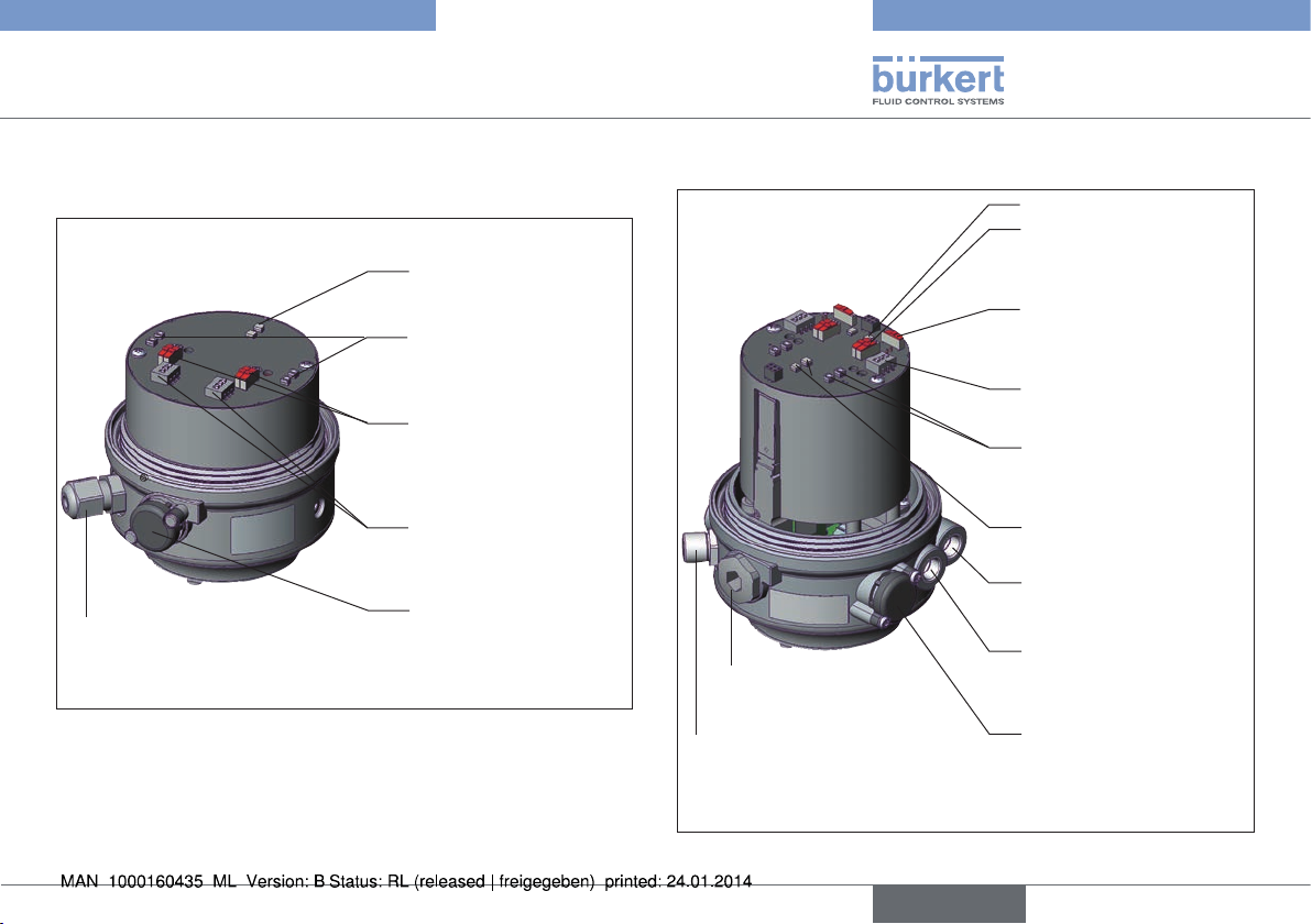
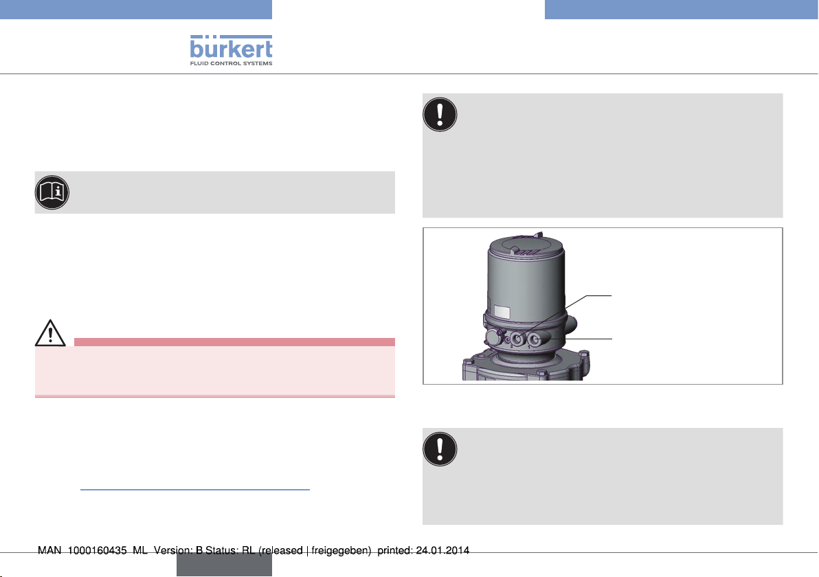
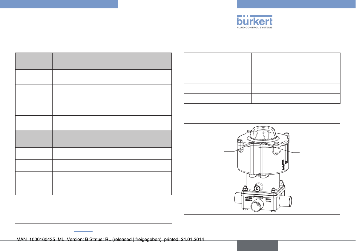
5.3 Structure of feedback head Type
8685
View without
transparent cap:
Electrical connection
Cable gland M12 x 1.5 or circular
plug-in connector M12 x 1
Fig. 1: Structure of feedback head Type 8685
AS interface
status LEDs
Drive status OPEN/
CLOSED LEDs
(end position)
Slide switch
Color selection of
end position
DIP switches
Select RV50/70/110
Pressure limiting valve
(for protection against
too high internal pressure
in case of error)
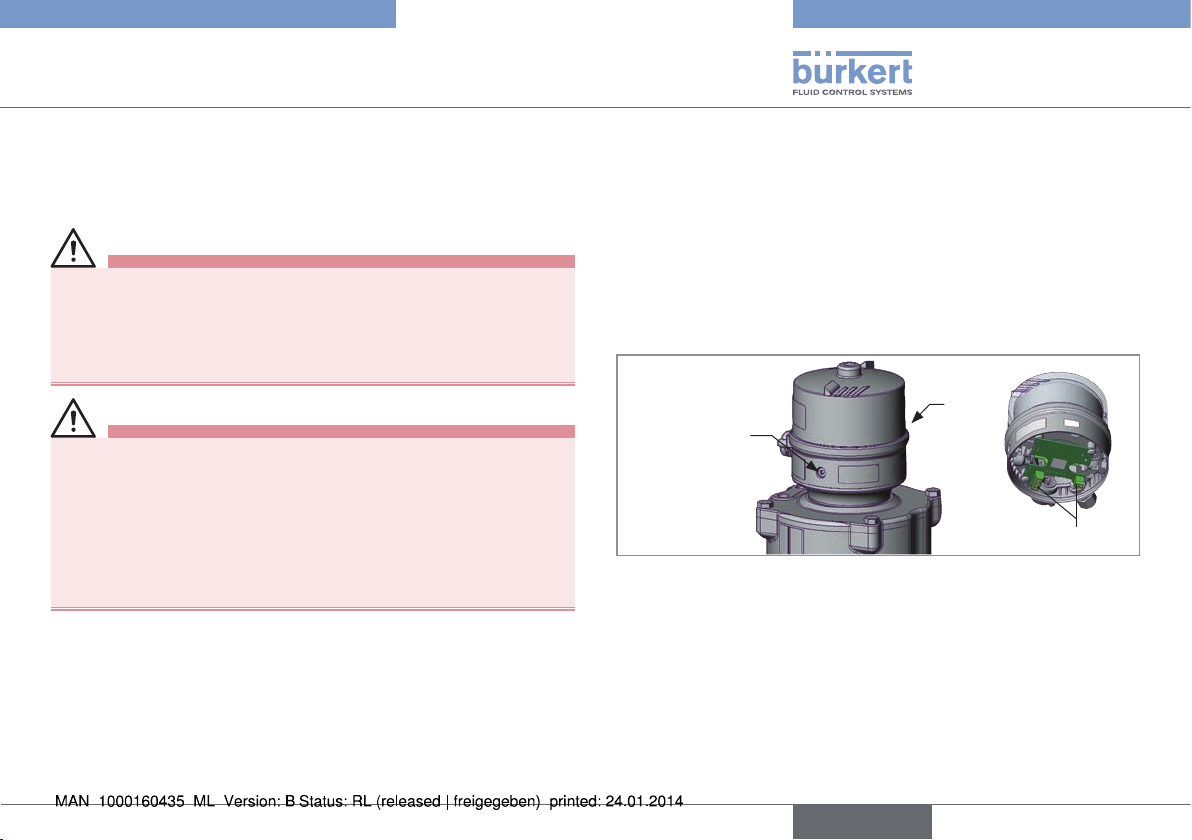
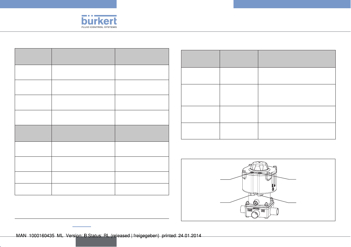
5.4 Structure of control head Type 8686
View without transparent
cap and body casing:
Dummy plug
M16 x 1.5
Electrical connection
Cable gland M12 x 1.5
or circular plug-in connector M12 x 1
Control valve status LED
Slide switch
Color selection of end
position
Slide switch
Pilot valve
(Service switch)
DIP switches
Select RV50/70/110
Actuator status OPEN/
CLOSED LEDs (end
position)
AS-Interface status
LEDs
Pilot air port
(label: 1)
Exhaust air port
(label: 3)
Pressure limiting valve
(for protection against too
high internal pressure in
case of error)
Fig. 2: Structure of control head Type 8686
English
9
Page 10
Type 8685 / 8686
Technical data
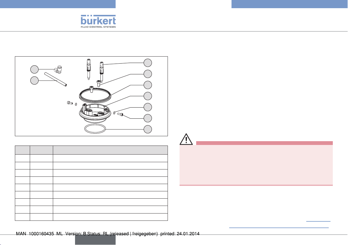
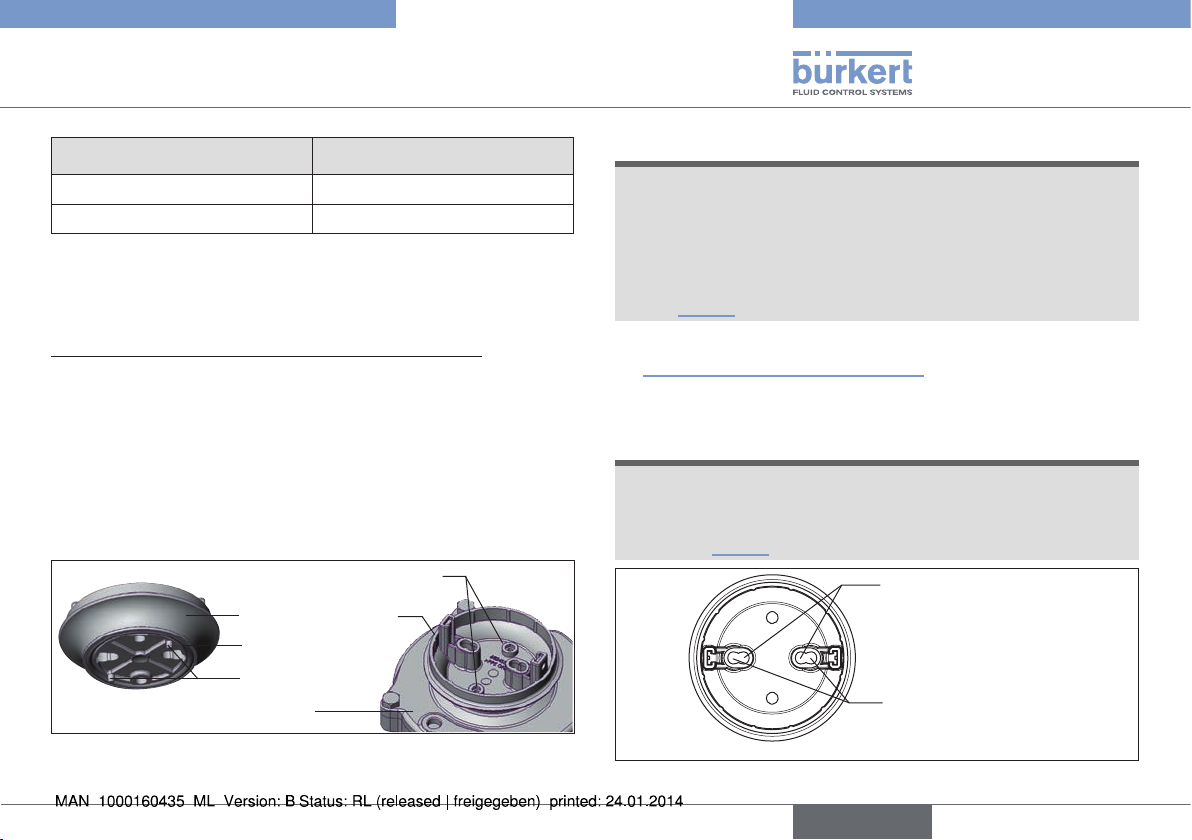
5.5 Structure of adapter set for
actuator Type 2036
2
9
8
Fig. 3: Adapter set for Type 2036
Item Quantity Designation
1 1 Robolux adaptation body
2 6 2 units each Switch spindle RV50, RV70, RV110 cpl.
3 1 O-ring 52 x 3 EPDM 75
4 1 Form seal
5 2 Cylinder head screw M6 x 12 A2 DIN 912
6 2 Cylinder head screw M4 with shaft
7 2 O-ring 3.5 x 1.5 EPDM 70
8 2 Hose 280 mm
9 4 Angular connection G1/8 SL6 Legris
Tab. 1: Parts list for adapter set
5
4
1
7
6
3
6 TECHNICAL DATA
6.1 Conformity
The feedback head Type 8685 and the control head Type 8686 comply
with EC directives in accordance with the EC Declaration of Conformity.
6.2 Standards
The applied standards, which verify conformity with the EC Directives, can be found on the EC Type Examination Certificate and / or
the EC Declaration of Conformity.
6.3 Operating conditions
WARNING!
Solar radiation and temperature fluctuations may cause malfunctions or leaks.
▶ If the device is used outdoors, do not expose it unprotected to
the weather conditions.
▶ Ensure that the permitted ambient temperature does not exceed
the maximum value or drop below the minimum value.
Ambient temperature 0 – +55 °C
Degree of protection IP65 / IP67 according to EN 60529
(only if cables, plugs and sockets have been
connected correctly and in compliance with
the exhaust air concept in chapter “8.3 Pneumatic installation of control head Type 8686”.
10
English
Page 11
Type 8685 / 8686
Technical data
6.4 Mechanical data
Dimensions See data sheet
Body material PPS, PC, VA
Sealing material outside EPDM
inside NBR
Stroke range of valve spindle RV50 actuator size 6 mm
RV70 actuator size 9.5 mm
RV110 actuator size 13.5 mm
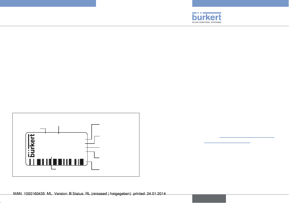
6.5 Type label
Example:
Supply voltage / control or
AS Interface profile
Type
8686 AS-i S-7.A.E
2x single pilot 3.0
Pmax 7bar
Tamb 0 ... +55°C
Ser. No. 001000
00XXXXXX
D-74653 Ingelfingen
W14UN
Identification number
Fig. 4: Example of type label
CE
Control function pilot valve
Max operating
pressure
Ambient
temperature
Serial number,
CE symbol
Bar code
6.6 Pneumatic data
Control medium neutral gases, air
Quality classes in accordance with
DIN ISO 8573-1
Dust content Class 5 Max. particle size 40 µm,
max. particle density 10 mg/m³
Water content of Class 3 max. pressure dew point - 20 °C or
min. 10 °C below the lowest
operating temperature
Oil content Class 5 max. 25 mg/m³
Temperature range
Control medium -10 – + 50 °C
Pressure range
Control medium 6 – 7 bar
(for further details see operating
instructions Type 2036 and
chapter “8.3 Pneumatic installation of
control head Type 8686”)
Air output of pilot valve 250 l
Connections Plug-in hose connector Ø 6 mm / 1/4"
/ min (for aeration and deaeration)
N
(QNn value according to definition for
pressure drop from 7 to 6 bar absolute)
Socket connection G1/8
English
11
Page 12

Type 8685 / 8686
Technical data
6.7 Electrical data for feedback head
Type 8685
6.7.1 Electrical data without bus control
24 V DC
Connections Cable gland M12 x 1.5, wrench size 15
(clamping area 3 – 6.5 mm)
with screw terminals
(nominal cross section 1.0 mm²,
max. cable cross-section 0.25 mm²)
Supply voltage 24 V DC ± 10%
- max. residual ripple 10%
Output max. 100 mA per output /
short circuit-proof
Display max. 20 mA
(2 end positions
= 2 LEDs)
6.7.2 Electrical data with AS-Interface bus
control
Connections Remote 975 mm AS-Interface cable
with circular plug-in connector
(M12 x 1, 4-pole)
Supply voltage 29.5 V – 31.6 V DC
(according to specification)
Max. power consumption 35 mA
12
English
Page 13
Type 8685 / 8686
Technical data
6.8 Electrical data
control head Type 8686
6.8.1 Electrical data without bus control
24 V DC
Connections Cable gland M12 x 1.5, wrench size 15
(clamping area 3 – 6.5 mm) with screw terminals
(nominal cross section 1.0 mm²,
max. cable cross-section 0.25 mm²)
Circular plug-in connector (M12 x 1, 8-pole)
Pilot valve
Supply voltage 24 V DC ± 10%
- max. residual ripple 10%
Power input 2 x 0.8 W
Output max. 100 mA per output / short
circuit-proof
Display max. 20 mA
(2 end positions = 2 LEDs)
Service:
Power consumption 90 mA
(2 end positions + 2 valves /
service switch on)
6.8.2 Electrical data with AS-Interface bus
control
Connections Remote 975 mm AS-Interface cable
with circular plug-in connector
(M12 x 1, 4-pole)
Supply voltage 29.5 V – 31.6 V DC
(according to specification)
Outputs
Max. switching capacity: 2 x 0.8 W via AS-Interface
Watchdog function integrated
Max. power consumption 120 mA
(2 valves when activated +
2 end positions)
Service:
Power consumption 105 mA
(2 end positions
+ 2 valves /
service switch on)
English
13
Page 14
Type 8685 / 8686
Assembly
7 ASSEMBLY
7.1 Safety instructions
DANGER!
Risk of injury from high pressure in the equipment/device.
▶ Before working on equipment or device, switch off the pressure
and deaerate/drain lines.
Risk of electric shock.
▶ Before working on equipment or device, switch off the power
supply and secure to prevent reactivation.
▶ Observe applicable accident prevention and safety regulations
for electrical equipment.
WARNING!
Risk of injury from improper assembly.
▶ Installation may only be carried out by authorized technicians
with the appropriate tools.
Risk of injury from unintentional activation of the system and
uncontrolled restart.
▶ Secure system from unintentional activation.
▶ Following assembly, ensure a controlled restart.
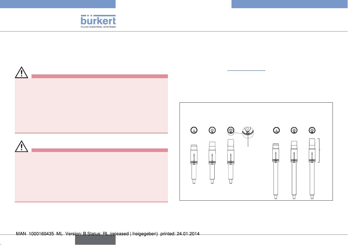
7.2 Assembly of Type 8685 and Type
8686 on the actuator Type 2036
An adapter set is required for assembly on the actuator Type 2036.
The adapter set (see “Fig. 3”, page 10) includes an adaptation body,
a form seal, three O-rings, four cylinder screws and three switch spindle
pairs. There are different adapter sets for feedback head and control
head. Because of the different working height for actuator sizes RV50,
RV70 and RV110, an adapter set contains different spindle lengths.
Switch Spindle Type 8685
RV110 RV70
Fig. 5: Switch spindle identification
RV50
Actuator
size
identification
Switch Spindle Type 8686
RV110 RV70
RV50
Cap
14
English
Page 15
Type 8685 / 8686
Assembly
Designation Order no.
Adapter set for Type 8685 684267
Adapter set for Type 8686 684268
Tab. 2: Adapter sets
Procedure:
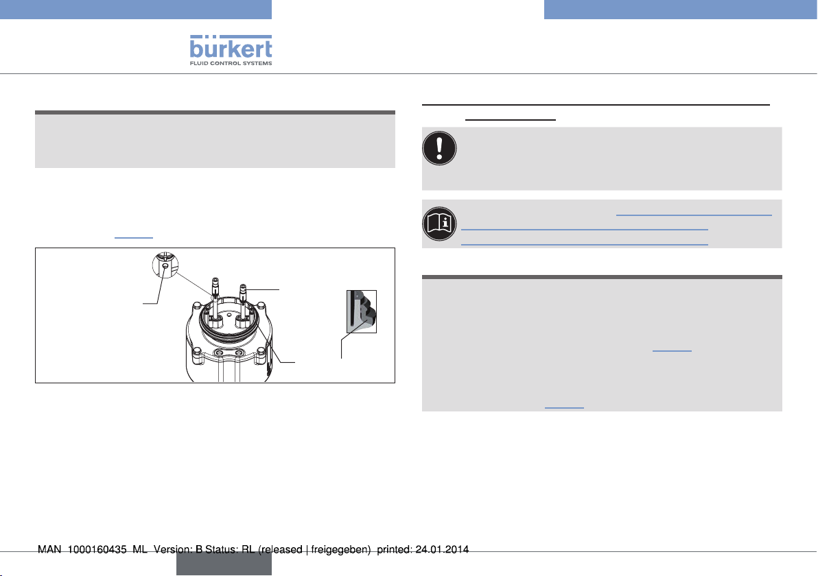
Step 1: Assembly of adaptation body on the actuator
→ Unscrew the transparent cap from the actuator.
→ Place the 52 x 3 O-ring in the profile on the bottom of the adap-
tation body.
→ Place the adaptation body on the actuator, paying close attention
to the coding pin.
→ Screw the adaptation body tightly onto the actuator with two
cylinder screws M6 x 12.
Cylinder screws M6 x 12
Adaptation body
O-ring 52 x 3
Coding pin
Actuator
Fig. 6: Assembly of adaptation body
NOTE!
Using a switch spindle that does not fit will result in irreparable destruction of the feedback head and/or control head
and the actuator.
▶ Use only switch spindles that match the actuator size. The cor-
responding actuator size identification (RV50, RV70, RV110)
for switch spindles are embossed on the front of the PVC cap
(see “Fig. 5”).
→ Select the switch spindle that matches the actuator size (see
“Fig. 5: Switch spindle identification”).
→ Wet the thread of two switch spindles that match the actuator
size with Loctite screw locking M290.
NOTE!
Using the wrong spindle lead-through will result in
malfunction.
▶ Use only the spindle lead-through that matches the actuator
size (see “Fig. 7”).
Spindle lead-through
for actuator size
RV50
Spindle lead-through
for actuator sizes
RV70 and RV110
Fig. 7: Spindle lead-through
English
15
Page 16
Type 8685 / 8686
Assembly
NOTE!
No detection or faulty detection of end positions.
▶ Do not change the position of the cap on the switch spindle.
▶ Use the hole ∅ 2.3 for fastening the switch spindle.
→ Push the switch spindles through the matching spindle lead-
throughs. The outside lead-throughs are designed for actuator
size RV70/110, while the inside lead-throughs for actuator size
RV50 (see “Fig. 7”).
Cap
Hole ∅ 2.3 for
screwing in the
switch spindle
Form seal
Fig. 8: Assembly of switch spindles and form seal
→ Using a suitable tool, screw the two switch spindles onto the
actuator spindles. There is a hole ∅ 2.3 on the spindle side for
this purpose (torque 1.0 Nm ± 0.1 Nm).
→ Place the form seal on the adaptation body (smaller diameter
points upwards).
Step 2: Assembly of the feedback head / control head on the
adaptation body
If the electrical connection is made with a cable gland, we
recommend connecting the wires at this point, since otherwise
the feedback head / control head will have to be removed again
for the electrical connection.
For electrical installation see: “9.2 Device version 24 V DC”
“Device connection for cable gland Type 8685”
“Device connection for cable gland Type 8686”
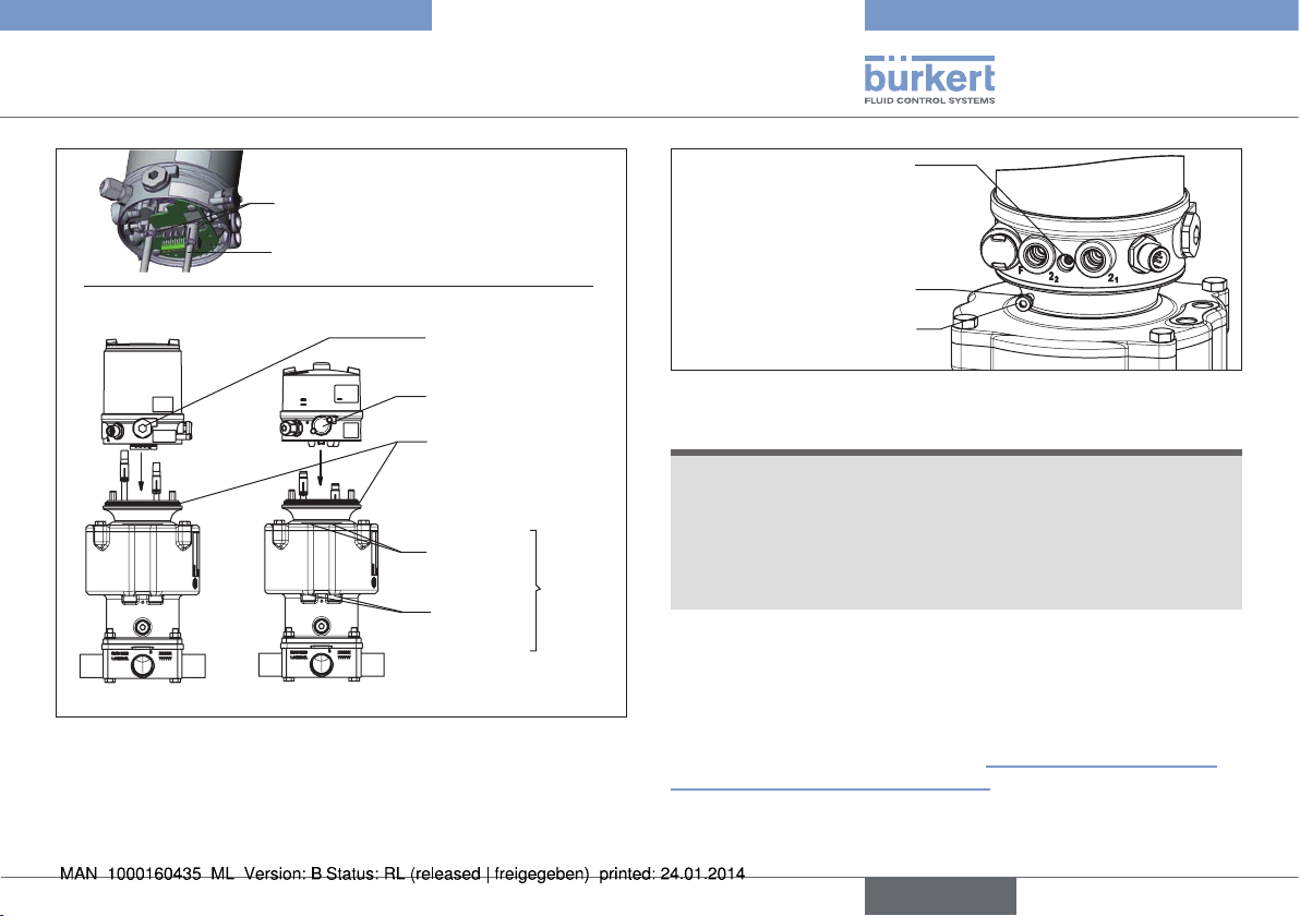
NOTE!
Faulty detection of end positions.
▶ For actuators with control function B (CFB, NO), the lower end
position must be approached before the feedback head / control
head is placed on the adaptation body. To do this, pressurize the
appropriate pilot air port of the actuator (“Fig. 9”).
▶ Make certain the feedback head / control head is correctly posi-
tioned relative to the actuator: The dummy plug or pressure-relief
valve must be located on the side of the pneumatic connections
of the actuator (see “Fig. 9”).
→ Place the feedback head / control head on the actuator. As you
do, note:
- The dummy plug or pressure-relief valve must be located on the
side of the pneumatic connections of the actuator.
- The switch spindles must lodge inside the recesses on the bottom
of the feedback head / control head. Do not move the caps onto
the switch spindles.
16
English
Page 17
Type 8686
Type 8685 / 8686
Assembly
Recess
Switch spindle
Type 8685
Dummy plug
Mounting hole of the
feedback head / control
head concentric with
square nut of the adap-
tation body
O-ring 3.5 x 1.5
Fastening screw M4
Pressure-relief valve
Form seal
Connection
SFB
Connection
SFA
Type 2036
Fig. 9: Assembly of feedback head / control head
→ Push the feedback head / control head onto the adaptation body
until no gap is visible on the form seal. Now align the mounting hole
of the feedback head / control head on each side with the square
nut of the adaptation body.
Fig. 10: Fastening of feedback head / control head
NOTE!
If the torque is too high when screwing in the fastening screw
or if the O-ring is missing, degree of protection IP65 / IP67 is
not ensured.
▶ The fastening screw may only be tightened to a maximum torque
of 0.5 Nm ± 0.1 Nm.
▶ Check the position of the O-ring.
connections
Pneumatic actuator
→ Use the two fastening screws M4 and matching O-rings to
fasten the feedback head / control head onto the adaptation
body (torque: 0.5 Nm ± 0.1 Nm).
The mechanical connection is already completed for the feedback
head after these two assembly steps. “Step 3: Assembly of pneumatic connection - install the actuator” must still be performed for
the control head.
English
17
Page 18
Type 8685 / 8686
Assembly
Control head Type 8686 only:
Step 3: Assembly of pneumatic connection - install the actuator
→ Screw the plug-in hose connectors onto the control head and the
actuator.
→ Cut the enclosed hoses (2 x 280 mm) to length as appropriate
for the device layout.
→ Using the hoses supplied in the accessory kit, make the pneumatic
connection between the control head and actuator according to
the control function (CF) with the following “Tab. 3: Overview of
pneumatic connections for actuator variants”.
Hoses
Plug-in hose
connectors
Fig. 11: Assembly of pneumatic connections
NOTE!
Damage or malfunction due to ingress of dirt and moisture.
▶ To comply with degree of protection IP65 / IP67, install an
exhaust air line on the unneeded pilot air port (for CFA, NC and
CFB, NO) in the dry area.
Pilot air outputs for
control head
Actuator 1
(left)
Pilot air port
2 (P2)
Pilot air port
1 (P1)
Fig. 12: Pneumatic connection
Actuator 2
(right)
Pilot air port
4 (P4)
Pilot air port
3 (P3)
18
English
Page 19
Type 8685 / 8686
Pneumatic installation
Type 2036 Actuator 1 Actuator 2
CF Connection CF Connection
D11, D55
CFA/CFA
D12
CFA/CFB
D21
CFB/CFA
D22
CFB/CFB
CFA
CFA
CFB
CFB
2
P1
1
P2: Deaeration
2
P1
1
P2: Deaeration
2
P2
1
P1: Deaeration
2
P2
1
P1: Deaeration
CFA
CFB
CFA
CFB
2
P4: Deaeration
2
P3: Deaeration
2
P4: Deaeration
2
P3: Deaeration
P3
2
P4
2
P3
2
P4
2
Tab. 3: Overview of pneumatic connections for actuator variants
CFA, NC: Valve closed in rest position (by spring force)
CFB, NO: Valve open in rest position (by spring force)
For the assignment of control connections see the installation and dimensional drawing included with delivery of the
valve or in the Type 2036 operating instructions.
8 PNEUMATIC INSTALLATION
The dimensions of the feedback head / control head and the different
complete device models, consisting of control, feedback head / control
head, actuator and valve, can be found in the relevant data sheets.
8.1 Safety instructions
DANGER!
Risk of injury from high pressure in the equipment/device.
▶ Before working on equipment or device, switch off the pressure
and deaerate/drain lines.
Risk of electric shock.
▶ Before working on equipment or device, switch off the power
supply and secure to prevent reactivation.
▶ Observe applicable accident prevention and safety regulations
for electrical equipment.
WARNING!
Risk of injury from improper installation.
▶ Installation may only be carried out by authorized technicians
with the appropriate tools.
Risk of injury from unintentional activation of the system and
uncontrolled restart.
▶ Secure system from unintentional activation.
▶ Following installation, ensure a controlled restart.
English
19
Page 20
Type 8685 / 8686
Pneumatic installation
8.2 Pneumatic installation of
feedback head Type 8685
The feedback head does not require a pilot air supply.
A description of the pneumatic installation of the actuator is
included in the valve operating instructions.
8.3 Pneumatic installation of control
head Type 8686
DANGER!
Risk of injury from high pressure in the equipment/device.
▶ Before working on equipment or device, switch off the pressure
and deaerate/drain lines.
Procedure:
→ Connect the control medium to the pilot air port (1)
(6 – 7 bar; instrument air, free of oil, water and dust).
→ Mount the exhaust air line or a silencer on the exhaust air port (3)
(see “Fig. 13: Pneumatic connection Type 8686”).
Important information for the problem-free functioning of
the device:
▶ The installation must not cause back pressure to build up.
▶ To make the connection, select a hose with sufficient cross
section.
▶ The exhaust air line must be designed in such a way that
no water or other liquid can get into the device through the
exhaust air connection (3).
Exhaust air port
Label: 3
Pilot air port
Label: 1
Fig. 13: Pneumatic connection Type 8686
Caution (exhaust air concept): In compliance with degree
of protection IP65 / IP67, an exhaust air line must be
installed in the dry area.
Always maintain an applied control pressure of at least
0.5 – 1 bar above the pressure which is required to move the
actuator to its end position.
20
English
Page 21
Type 8685 / 8686
Electrical installation
9 ELECTRICAL INSTALLATION
9.1 Safety instructions
DANGER!
Risk of electric shock.
▶ Before working on equipment or device, switch off the power
supply and secure to prevent reactivation.
▶ Observe applicable accident prevention and safety regulations
for electrical equipment.
WARNING!
Risk of injury from improper installation.
▶ Installation may only be carried out by authorized technicians
with the appropriate tools.
Risk of injury from unintentional activation of the system and
uncontrolled restart.
▶ Secure system from unintentional activation.
▶ Following installation, ensure a controlled restart.
9.2 Device version 24 V DC
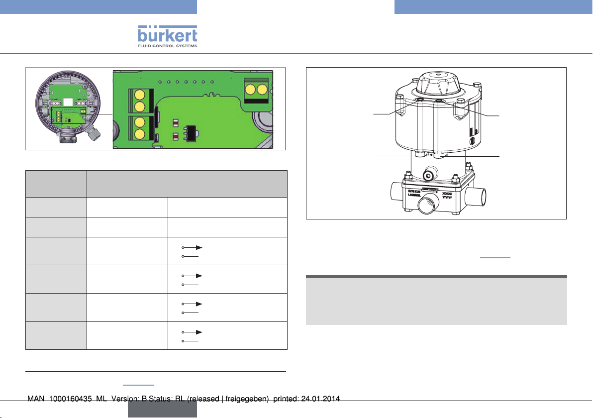
9.2.1 Electrical installation for feedback
head Type 8685
Device connection for cable gland Type 8685
→ Use a cable cross-section of 0.25 mm² for the electrical
connection.
Fastening
screws
M4 (2x)
Screw terminals
Fig. 14: Position of screw terminals Type 8685
→ Loosen the fastening screws M4 and pull the feedback head up
(only if the feedback head is already installed).
→ Install the cable gland, if necessary (approx. 1,5 Nm).
→ Guide the cables through the cable gland.
English
21
Page 22
Type 8685 / 8686
Electrical installation
Top1
Bot1
Top2
Bot2
Fig. 15: Designation on PCB Type 8685
Designation
on PCB
24 V
GND
Top 1
Bot 1
Top 2
Bot 2
Assignment
Supply voltage + 24 V DC ±10%
Supply voltage - GND
Top end position Top actuator 1
Bottom end position Bot actuator 1
Top end position Top actuator 2
Bottom end position Bot actuator 2
1)
Tab. 4: Connection for cable gland Type 8685
GND24V
24 V / 0 V (max. 0.1 A)
GND (7)
24 V / 0 V (max. 0.1 A)
GND (7)
24 V / 0 V (max. 0.1 A)
GND (7)
24 V / 0 V (max. 0.1 A)
GND (7)
Actuator 1
(left)
Pilot air port
2 (P2)
Pilot air port
1 (P1)
Actuator 2
(right)
Pilot air port
4 (P4)
Pilot air port
3 (P3)
Fig. 16: Pneumatic connection
→ Connect the wires (see pin assignment in “Tab. 4”).
NOTE!
Damage or malfunction due to ingress of dirt and moisture.
▶ To ensure degree of protection IP65 / IP67, tighten the union
nut of the cable gland according to the cable size you are using
(approx. 1.5 Nm).
→ Tighten the union nut of the cable gland on the body (approx. 1.5
Nm).
1) Actuator assignment see “Fig. 16”.
22
English
Page 23
Type 8685 / 8686
Electrical installation
NOTE!
Faulty detection of end positions.
▶ For actuators with control function B (CFB, NO), the lower end
position must be approached before the feedback head is placed
on the adaptation body. To do this, pressurize the appropriate pilot
air port of the actuator (“Fig. 9”).
▶ Make certain the feedback head is correctly positioned relative
to the actuator: The dummy plug or pressure-relief valve must be
located on the side of the pneumatic connections of the actuator
(see “Fig. 9”).
→ Place the feedback head on the actuator. As you do, note:
- The dummy plug or pressure-relief valve must be located on the
side of the pneumatic connections of the actuator.
- The switch spindles must lodge inside the recesses on the
bottom of the feedback head. Do not move the caps onto the
switch spindles.
→ Push the feedback head onto the adaptation body until no gap is
visible on the form seal. Now align the mounting hole of the feedback
head on each side with the square nut of the adaptation body.
NOTE!
If the torque is too high when screwing in the fastening screw
or if the O-ring is missing, degree of protection IP65 / IP67 is
not ensured.
▶ The fastening screw may only be tightened to a maximum torque
of 0.5 Nm ± 0.1 Nm.
▶ Check the position of the O-ring.
→ Use the two fastening screws M4 and matching O-rings to
fasten the feedback head onto the adaptation body (torque: 0.5
Nm ± 0.1 Nm).
When the supply voltage is applied, the feedback head is operating.
→ Before the device can be used, the basic settings (see section
“10.3.1 Basic settings”) must still be made on the feedback
head.
English
23
Page 24
Type 8685 / 8686
Electrical installation
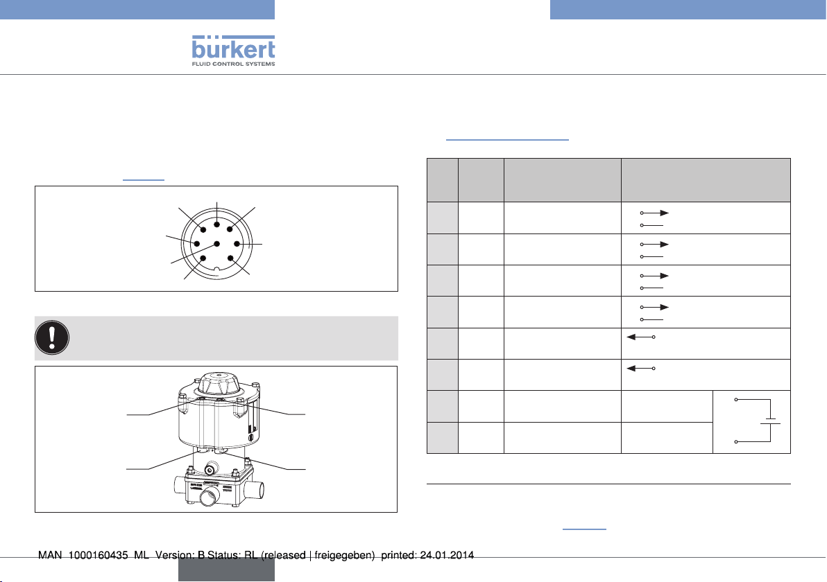
9.2.2 Electrical installation of control head
Type 8686
Device connection for circular plug-in connector Type 8686
→ Connect the circular plug-in connector of the control head as
described in “Tab. 5”.
6
7
8
Fig. 17: Assignment of circular plug (M12 x 1, 8-pole)
Use only straight connecting socket.
Actuator 1
(left)
Pilot air port
2 (P2)
Pilot air port
1 (P1)
Fig. 18: Pneumatic connection
5
4
3
1
2
Actuator 2
(right)
Pilot air port
4 (P4)
Pilot air port
3 (P3)
When the supply voltage is applied, the control head is operating.
→ Before the device can be used, the basic settings (see section
“10.3.1 Basic settings”) must still be made on the control head.
Wire
Pin
color
white
1
brown
2
green
3
yellow
4
gray
5
pink
6
blue Supply voltage – GND
7
red Supply voltage + 24 V DC ±10%
8
Assignment
2)
Bottom end position Bot actuator 2
Top end position Top actuator 2
Bottom end position Bot actuator 1
Top end position Top actuator 1
Valve control Y2
Actuator 2 activated
Valve control Y1
Actuator 1 activated
Tab. 5: Connection for circular plug-in connector Type 8686
2) The indicated colors refer to the connecting cable available as an
accessory (919061).
3) Actuator assignment see “Fig. 18”.
3)
External circuit
1
2
3
4
24 V / 0 V (max. 0.1 A)
GND (7)
24 V / 0 V (max. 0.1 A)
GND (7)
24 V / 0 V (max. 0.1 A)
GND (7)
24 V / 0 V (max. 0.1 A)
GND (7)
high active, to activate
5
connect with 24 V
high active, to activate
6
connect with 24 V
7
8
24
English
Page 25
Type 8685 / 8686
Electrical installation
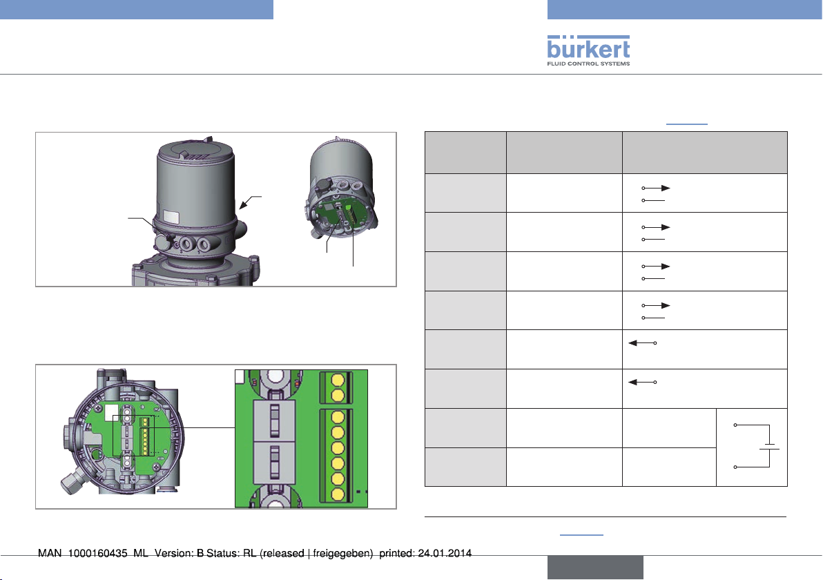
Device connection for cable gland Type 8686
→ Use a cable cross-section of 0.25 mm² for the electrical connection.
Fastening
screws
M4 (2x)
Cable holder
Screw terminals
Fig. 19: Position of screw terminals Type 8686
→ Loosen the fastening screws M4 and pull the control head up
(only if the control head is already installed).
→ Install the cable gland, if necessary (approx. 1,5 Nm).
24V
GND
Valve1
Valve2
Top1
Bot1
Top2
Bot2
Fig. 20: Designation on PCB Type 8686
→ Guide the cables through the cable gland.
→ Connect the wires (see pin assignment in “Tab. 6”).
Designation
on PCB
Bot2
Top2
Bot1
Top1
Valve2
Valve1
GND
24V
Assignment
Bottom end position Bot actuator 2
Top end position Top actuator 2
Bottom end position Bot actuator 1
Top end position Top actuator 1
Valve control Y2
Actuator 2 activated
Valve control Y1
Actuator 1 activated
Supply voltage - GND
Supply voltage + 24 V DC ±10%
Tab. 6: Connection for cable gland Type 8686
4) Actuator assignment see “Fig. 18”.
4)
External circuit
24 V / 0 V (max. 0.1 A)
GND (7)
24 V / 0 V (max. 0.1 A)
GND (7)
24 V / 0 V (max. 0.1 A)
GND (7)
24 V / 0 V (max. 0.1 A)
GND (7)
high active, to activate
connect with 24 V
high active, to activate
connect with 24 V
English
25
Page 26
Type 8685 / 8686
Electrical installation
NOTE!
Malfunction due to damaged wires.
▶ To keep the spindle guides free, guide all wires through the
cable holders.
Damage or malfunction due to ingress of dirt and moisture.
▶ To ensure degree of protection IP65 / IP67, tighten the union
nut of the cable gland according to the cable size you are using
(approx. 1.5 Nm).
→ Guide all wires through the cable holders.
→ Tighten the union nut of the cable gland on the body (approx. 1.5
Nm).
NOTE!
Faulty detection of end positions.
▶ For actuators with control function B (CFB, NO), the lower end
position must be approached before the control head is placed
on the adaptation body. To do this, pressurize the appropriate pilot
air port of the actuator (“Fig. 9”).
▶ Make certain the control head is correctly positioned relative to
the actuator: The dummy plug or pressure-relief valve must be
located on the side of the pneumatic connections of the actuator
(see “Fig. 9”).
→ Place the control head on the actuator. As you do, note:
- The dummy plug or pressure-relief valve must be located on the
side of the pneumatic connections of the actuator.
- The switch spindles must lodge inside the recesses on the bottom
of the control head. Do not move the caps onto the switch spindles.
→ Push the control head onto the adaptation body until no gap is
visible on the form seal. Now align the mounting hole of the control
head on each side with the square nut of the adaptation body.
NOTE!
If the torque is too high when screwing in the fastening screw
or if the O-ring is missing, degree of protection IP65 / IP67 is
not ensured.
▶ The fastening screw may only be tightened to a maximum torque
of 0.5 Nm ± 0.1 Nm.
▶ Check the position of the O-ring.
→ Use the two fastening screws M4 and matching O-rings to
fasten the control head onto the adaptation body (torque:
0.5 Nm ± 0.1 Nm).
When the supply voltage is applied, the control head is operating.
→ Before the device can be used, the basic settings (see section
“10.3.1 Basic settings”) must still be made on the control head.
26
English
Page 27
Type 8685 / 8686
Electrical installation
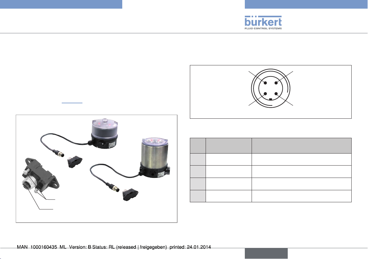
9.3 Device version AS-Interface
9.3.1 Electrical installation feedback head
and control head
The feedback head and control head are electrically connected by a
multi-pole cable (M12 circular plug-in connector) and ribbon cable
terminal. The circular plug can simply be connected with the ribbon
cable terminal (see “Fig. 21”).
Screws
M12 plug-in connector branch circuit
Wiring diagram of circular plug M12
The view shows the image from the front looking at the pins, the solder
connections are behind them.
Pin 4:
NC
Pin 1:
Bus +
Fig. 22: Bus connection
Pin Designation Assignment
Bus + AS-Interface bus line +
1
NC not used
2
Bus – AS-Interface bus line –
3
NC not used
4
Tab. 7: Pin assignment of circular plug-in connector for
AS-Interface
Pin 3:
Bus –
Pin 2:
NC
Fig. 21: Feedback head / control head with multi-pole cable and
ribbon cable terminal
English
27
Page 28
Type 8685 / 8686
Electrical installation
Handling the ribbon cable terminal
The multi-pole cable features a ribbon cable terminal - with M12 plug-in
connector branch circuit - for AS-Interface cable harness. The ribbon
cable terminal contacts the AS-Interface cable harness by means of
penetration technology which allows installation by “clipping in” the ASInterface cable harness without cutting and without removing insulation.
Procedure:
→ Open the ribbon cable terminal
(loosen screws and remove cover).
→ Insert cable harness to fit closely.
→ Close ribbon cable terminal again.
→ Tighten the screws
Loosen the thread-forming screws slightly (approx. 3/4 turn to the
left) and position them on the existing threaded hole and screw in.
9.3.2 AS-Interface connection
AS-Interface (Actuator Sensor Interface) is a field bus system
which is used primarily for networking binary sensors and actuators
(slaves) with a higher-level control (master).
Bus line
Unshielded two-wire line (AS-Interface line as AS-Interface cable
harness) along which both information (data) and energy (power
supply voltage for the actuators and sensors) are transmitted.
Network topology
Freely selectable within wide limits, i.e. star, tree and line networks
are possible. Further details are described in the AS-Interface Specification (A/B slave model conforms to the version 3.0 specification
9.3.3 Technical Data for AS-Interface PCBs
Supply: via AS-Interface (29.5 V – 31.6 V)
Control head outputs: Valve Y1 and valve Y2,
each with max. 0.8 W,
Power reduction after approx. 100 ms
with integrated watchdog function
Certification: Feedback head: Certificate No. 94701
based on version 3.0
Control head: Certificate No. 94801
based on version 3.0
9.3.4 Programming data
Programming data for feedback head Type 8685
I/O configuration 0 hex
ID code
Extended ID code 1 7 hex
Extended ID code 2 E hex
Profile S-0.A.E
Tab. 8: Programming data for feedback head Type 8685
A hex (see below for bit
configuration)
28
English
Page 29
Type 8685 / 8686
Electrical installation
Bit configuration
Data bit
Inputs
D0
D1
D2
D3
Data bit
Outputs
Function Assignment
Top end position Top actuator 1
Bottom end position Bot actuator 1
Top end position Top actuator 2
Bottom end position Bot actuator 2
0 Top not reached
1 Top reached
0 Bot not reached
1 Bot reached
0 Top not reached
1 Top reached
0 Bot not reached
1 Bot reached
Function Assignment
5)
5)
D0 - not used
D1 - not used
D2 - not used
D3 - not used
Tab. 9: Bit configuration of AS-Interface for feedback head Type 8685
Programming data for control head Type 8686:
I/O configuration 7 hex
ID code A hex (see below for bit configuration)
Extended ID code 1 7 hex
Extended ID code 2 E hex
Profile S-7.A.E
Tab. 10: Programming data for control head Type 8686
Actuator 1
(left)
Pilot air port
2 (P2)
Pilot air port
1 (P1)
Actuator 2
(right)
Pilot air port
4 (P4)
Pilot air port
3 (P3)
Parameter bits have no function.
5) Actuator assignment see “Fig. 23”.
Fig. 23: Pneumatic connection
English
29
Page 30
Type 8685 / 8686
Electrical installation
Bit configuration
Data bit
Inputs
D0
D1
D2
D3
Data bit
Outputs
Function Assignment
Top end position Top actuator 1
Bottom end position Bot actuator 1
Top end position Top actuator 2
Bottom end position Bot actuator 2
Function Assignment
D0 Pilot valve Y1
D1 Pilot valve Y2
0 Top not reached
1 Top reached
0 Bot not reached
1 Bot reached
0 Top not reached
1 Top reached
0 Bot not reached
1 Bot reached
0 Pilot valve OFF
1 Pilot valve ON
0 Pilot valve OFF
1 Pilot valve ON
6)
6)
D2 - not used
D3 - not used
Tab. 11: Bit configuration of AS-Interface for control head Type 8686
Parameter bits have no function.
9.3.5 LED status display for AS-Interface
Status LED 1
(green)
off off POWER OFF
off on
on off OK
flashing on Slave address equals 0
Tab. 12: LED status display for AS-Interface
Actuator 1
Pilot air port
2 (P2)
Pilot air port
1 (P1)
(left)
Status LED 2
(red)
No data traffic (expired Watch
Dog at slave address does not
equal 0)
Actuator 2
(right)
Pilot air port
4 (P4)
Pilot air port
3 (P3)
6) Actuator assignment see “Fig. 24”.
30
English
Fig. 24: Pneumatic connection
Page 31

Type 8685 / 8686
Control and display
10 CONTROL AND DISPLAY
10.1 Control and display elements for
feedback head Type 8685
10.1.1 Device version 24 V DC
The items listed below are designed separately for actuator 1 and 2.
Display elements:
• Status of actuator (end position)
The display elements are designed in the form of an LED.
Control elements:
• DIP switch for selecting actuator size RV50, RV70, RV110
• Slide switch for color selection of end position
If the transparent cap is unscrewed, follow the instructions
in “Step 4: Closing the transparent cap / body casing”,
page 36.
Slide switch
Color selection of end position
Actuator 1
LEDs
Status of actuator 1
(end position)
DIP switch -
actuator 1
Fig. 25: Control and display elements for 24 V DC feedback head
Slide switch
Color selection of end position
Actuator 2
LEDs
Status of actuator 2
(end position)
DIP switch actuator 2
English
31
Page 32

Type 8685 / 8686
Control and display
10.1.2 Device version AS-Interface
Other than the AS-Interface bus status, the items listed below are
designed separately for actuator 1 and 2.
Display elements:
• AS-Interface bus status
• Status of actuator (end position)
The display elements are designed in the form of an LED.
Control elements:
• DIP switch for selecting actuator size RV50, RV70, RV110
• Slide switch for color selection of end position
If the transparent cap is unscrewed, follow the instructions
in “Step 4: Closing the transparent cap / body casing”,
page 36.
AS Interface bus status
Slide switch for
color selection of end position
Actuator 1
LEDs
Status of actuator 1
(end position)
DIP switch -
actuator 1
LEDs
Slide switch for
color selection of end position
Actuator 2
LEDs
Status of actuator 2
(end position)
DIP switch actuator 2
32
Fig. 26: Control and display elements for AS-Interface feedback
head
English
Page 33

Type 8685 / 8686
Control and display
10.2 Control and display elements for
control head Type 8686
The items listed below are designed separately for actuator 1 and 2.
Device versions 24 V DC and AS-Interface have the same display
and control PCB.
The AS-Interface bus status LEDs are accordingly inactive for the
24 V DC device version.
Display elements:
• AS-Interface bus status
• Status of actuator (end position)
• Status of pilot valve
The display elements are designed in the form of an LED.
Control elements:
• DIP switch for selecting actuator size RV50, RV70, RV110
• Slide switch for color selection of end position
• Slide switch for direct activation of pilot valves (service switch)
If the transparent cap / the body casing is unscrewed,
follow the instructions in “Step 4: Closing the transparent
cap / body casing”, page 36.
LED status of pilot valve
Actuator 1
Slide switch
(service switch)
Pilot valve for actuator 1
DIP switch -
actuator 1
LEDs
Status of actuator 1
(end position)
Slide switch
Color selection of end position
Actuator 1
AS Interface bus status
LED status of pilot valve
Actuator 2
Slide switch
(service switch)
Pilot valve for actuator 2
DIP switch actuator 2
LEDs
Status of actuator 2
(end position)
Slide switch
Color selection of end position
Actuator 2
LEDs
Fig. 27: Control and display elements - control head
English
33
Page 34

Type 8685 / 8686
Control and display
10.3 Control
10.3.1 Basic settings
To ensure the function of Types 8685 and 8686, these basic settings must be made before start-up in the isolated state.
DANGER!
Risk of electric shock.
▶ Before working on equipment or device, switch off the power
supply and secure to prevent reactivation.
▶ Observe applicable accident prevention and safety regulations
for electrical equipment.
→ Unscrew the transparent cap.
→ Perform steps 1 to 4.
Step 1: Select the actuator size
The control elements are designed for one actuator side only.
Switch only one DIP switch element per actuator size to
active, depending on the actuator size (see actuator type
label). Only one uniform actuator size needs to be selected
on both actuator sides.
Incorrect settings of the DIP switches result in malfunctions
or no function of the end position feedback.
→ Pushing a DIP switch element to the “ON” position causes the
end position sensors of the selected actuator size to be activated.
Type 8686
Type 8685
RV110
RV70
RV50
ACTUATOR
Fig. 28: Selection of actuator size via DIP switch
Step 2: Change the assignment of the end position LEDs
(actuator status)
You can set the color assignment of the end positions with these
slide switches. You can indicate for each color whether it applies to
the Top (upper end position) or Bot (lower end position).
The slide switches for color selection must be unambiguously selected inside the actuator chamber, i.e. both
switches must be up or both must be down.
Incorrect settings of these switches will result in an
incorrect visual interpretation of end position detection, but
the end position detection will still be correct.
ON
ON
1 2 3
34
English
Page 35

Type 8685 / 8686
Control and display
Typ 8686
Typ 8685
Fig. 29: Color assignment of end positions via slide switch
Refer to the PCB labeling in the table below
Switch position for one
actuator side
Both switches up End position Top yellow /
Both switches down End position Top green /
Switch up/down - Invalid state Switch down/up - Invalid state -
Tab. 13: Color assignment of end positions
The following function is set in the factory:
Color Actuator status
Green LED lit Lower end position
Yellow LED lit Upper end position
Tab. 14: Assignment of status of actuator LEDs (end position)
Actuator status LED
End position Bot green
End position Bot yellow
gn ye
Bot
Top
Top
Bot
Step 3: Reference movement for spindle adjustment
To make the fine adjustment of the spindle for actuator size, it is essential
to move both spindles from the lower to the top end position.
Procedure for Type 8685:
Actuator with design control function A (CFA, NC):
→ Under maximum control pressure, move the spindles up by acti-
vating the actuator chambers.
→ After the end position is reached (preselected LED is lit), turn off
the control pressure. The spindle moves to the lower end position.
LED for end position Bot is lit with the selected color.
Actuator with design control function B (CFB, NO):
→ Under maximum control pressure, move the spindles down by
activating the actuator chambers.
→ After the end position is reached (preselected LED is lit), turn
off the control pressure. The spindle moves to the upper end
position. The corresponding LED for the end position is lit with
the selected color.
English
35
Page 36

Type 8685 / 8686
Control and display
Procedure for Type 8686:
→ Under maximum control pressure, switch the service switch to “On”.
The spindle moves to the upper end position.
→ After the end position is reached (preselected actuator status LED
is lit), switch the service switch back to “Off”. The spindle moves
to its initial position. The corresponding actuator status LED for the
end position is lit with the selected color.
Service switch
Service
OFF
ON
Service
ON
OFF
Pilot valve status LED
Fig. 30: Spindle adjustment
Step 4: Closing the transparent cap / body casing
→ Check that the seal is correctly positioned in the transparent cap
/ body casing (see “Fig. 31”).
NOTE!
Damage or malfunction due to ingress of dirt and moisture.
▶ To comply with degree of protection IP65 / IP67, screw in the
transparent cap / body casing all the way.
→ Close the transparent cap / body casing (auxiliary tool for
installing the cover: 6740777)).
Transparent cap
Seal
transparent cap
Type 8685
Body casing
Seal
body casing
Type 8686
Fig. 31: Position of the seal in the transparent cap / body casing
The device is now configured and ready for operation.
7) The auxiliary tool for installing the cover (674077) is available through
your Bürkert sales office.
36
English
Page 37

Type 8685 / 8686
Control and display
10.3.2 Changing the settings
Procedure:
→ Unscrewing the transparent cap makes the slide switches and DIP
switches accessible.
→ Select the actuator size with the DIP switches. Only one uniform
actuator size needs to be selected on both actuator sides (see
valve type label).
→ Use the “Tab. 13: Color assignment of end positions” or the labeling
on the PCB to assign the desired color to the actuator status LEDs
(end position).
→ Check that the seal is correctly positioned in the transparent cap
/ body casing (see “Fig. 31”).
NOTE!
Damage or malfunction due to ingress of dirt and moisture.
▶ To comply with degree of protection IP65 / IP67, screw in the
transparent cap / body casing all the way.
→ Close the transparent cap / body casing (auxiliary tool for
installing the cover: 6740778)).
8) The auxiliary tool for installing the cover (674077) is available through
your Bürkert sales office.
10.3.3 Manual activation of pilot valves
with the control head Type 8686
The pilot valves can be switched with the service switches. With
control function A, the spindle moves up with switch position
“On”. With control function A, the spindle moves down with switch
position “On”.
Slide switch
(service switch)
Pilot valve for actuator 1
Service
ON
OFF
LED status
Pilot valve for actuator 1
Fig. 32: Service switch and status LEDs for pilot valve (Type 8686)
Procedure:
Voltage is absolutely essential on the device!
Slide switch
(service switch)
Pilot valve for actuator 2
Service
OFF
ON
LED status
Pilot valve for actuator 2
→ Unscrewing the transparent cap makes the service switches
accessible.
→ Switch the relevant pilot valve with the service switches.
→ Check that the seal is correctly positioned in the transparent cap
/ body casing (see “Fig. 31”).
English
37
Page 38

Type 8685 / 8686
Control and display
NOTE!
Damage or malfunction due to ingress of dirt and moisture.
▶ To comply with degree of protection IP65 / IP67, screw in the
transparent cap / body casing all the way.
→ Close the transparent cap / body casing (auxiliary tool for
installing the cover: 6740779)).
Procedure for replacing the diaphragm for Type 2036
Voltage is absolutely essential on the device!
→ Unscrewing the transparent cap makes the service switches
accessible.
→ Replace the diaphragm as described in the operating instruc-
tions for Type 2036.
→ After the diaphragm is replaced, perform a reference movement for
spindle adjustment (see “10.3.1 Basic settings”, step 3).
→ Check that the seal is correctly positioned in the transparent cap
/ body casing (see “Fig. 33”).
NOTE!
Damage or malfunction due to ingress of dirt and moisture.
▶ To comply with degree of protection IP65 / IP67, screw in the
transparent cap / body casing all the way.
→ Close the transparent cap (auxiliary tool for installing the cover:
6740779)).
Body casing
Seal
body casing
Type 8686
Fig. 33: Position of the seal in the body casing
9) The auxiliary tool for installing the cover (674077) is available through
your Bürkert sales office.
38
English
Page 39

Type 8685 / 8686
Safety positions
11 SAFETY POSITIONS
Safety positions after failure of the electrical or pneumatic auxiliary
power:
Actuator
type
up
down
up
down
Tab. 15: Safety positions
Designation
single-acting
Control
function A
single-acting
Control
function B
Safety positions after failure
of the auxiliary power
electrical pneumatic
down down
up up
12 MAINTENANCE
12.1 Safety instructions
DANGER!
Risk of injury from high pressure in the equipment/device.
▶ Before working on equipment or device, switch off the pressure
and deaerate/drain lines.
Risk of electric shock.
▶ Before working on equipment or device, switch off the power
supply and secure to prevent reactivation.
▶ Observe applicable accident prevention and safety regulations
for electrical equipment.
WARNING!
Risk of injury from improper maintenance.
▶ Maintenance may only be carried out by authorized technicians
with the appropriate tools.
Risk of injury from unintentional activation of the system and
uncontrolled restart.
▶ Secure system from unintentional activation.
▶ Following maintenance, ensure a controlled restart.
English
39
Page 40

Type 8685 / 8686
Maintenance
12.2 Service at the air intake filter
DANGER!
Risk of injury from high pressure in the equipment/device.
▶ Before working on equipment or device, switch off the pressure
and deaerate/drain lines.
To protect the internal pilot valves and the actuator, the control air is
filtered.
The direction of flow of the air intake filter in installed state is from
the inside to the outside through the filter material.
Quick connector
O-ring
Air intake filter
Fig. 34: Service at the air intake filter
Procedure:
→ Unlock the quick connector by pressing the holding element and
pulling out the air intake filter (if necessary, use a suitable tool in
between the recesses in the head of the filter).
→ Clean the filter or, if necessary, replace the filter.
→ Check inner O-ring and, if required, clean.
→ Insert the air intake filter all the way into the quick connector.
DANGER!
Risk of injury due to improper installation.
▶ Ensure that the air intake filter is installed correctly.
→ Check that the air intake filter is secure.
40
English
Page 41

Type 8685 / 8686
Malfunctions
13 MALFUNCTIONS
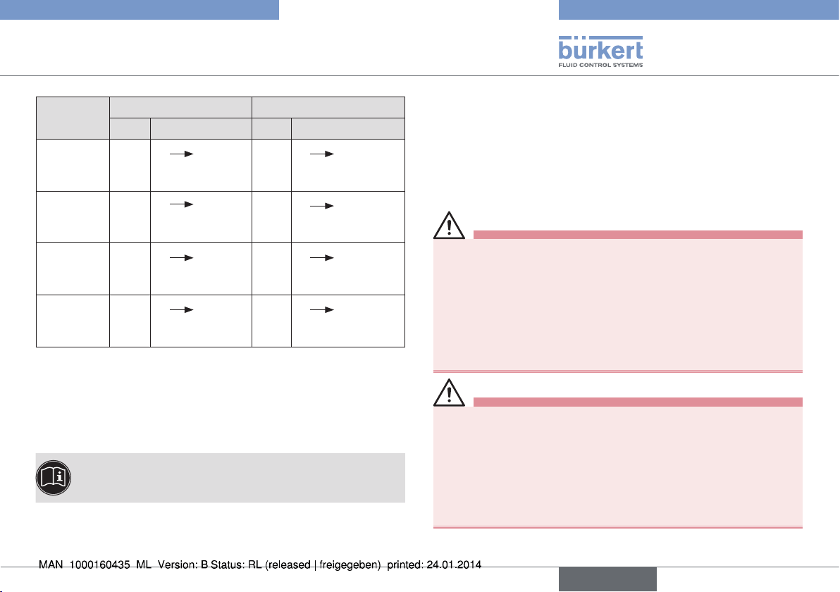
Malfunction Cause and remedial action
End position is
not detected
No or inadequate supply voltage
→ Check the electrical connection and supply
voltage
Wrong size of switch spindles from the adapter
set
→ Replace switch spindles
Wrong spindle lead-through selected for
spindle installation
→ Push the switch spindle through the
matching spindle lead-through
Wrong actuator size selected with the DIP
switches
→ Select the matching actuator size
Cap of the switch spindle moved by force
during assembly
→ Remove the feedback head / control head
→ Pull the cap towards the end of the switch
spindle until you can see one groove
→ Install the feedback head / control head
→ Perform a reference movement for spindle
adjustment
Malfunction Cause and remedial action
Faulty detection
of end position
Wrong actuator size selected with the DIP
switches
→ Select the matching actuator size
More than one actuator size selected with the
DIP switches
→ Select the matching actuator size
Feedback head / control head not mounted in
the correct position
→ Mount the feedback head / control head in
the correct position (see “Fig. 9”)
Incorrect
display of
actuator status
LED
Actuator does
not switch
Color selection switch not correctly selected
→ Select the color assignment correctly (both
up or both down, see section “10.3.1 Basic
settings” “Fig. 29”)
No or inadequate supply voltage
→ Check the electrical connection and supply
voltage
Pressure supply too low
→ Check the control pressure
Faulty hose system
→ Check the pneumatic connections
English
41
Page 42

Type 8685 / 8686
Malfunctions
Malfunction Cause and remedial action
AS-Interface
bus status
LEDs off
No or inadequate supply voltage
→ Check contact of ribbon cable terminal with
AS-Interface line
→ Ensure supply voltage is present on the AS-
Interface line
Tab. 16: Malfunctions
14 SHUTDOWN
14.1 Safety instructions
DANGER!
Risk of injury from high pressure in the equipment/device.
▶ Before working on equipment or device, switch off the pressure
and deaerate/drain lines.
Risk of electric shock.
▶ Before working on equipment or device, switch off the power
supply and secure to prevent reactivation.
▶ Observe applicable accident prevention and safety regulations
for electrical equipment.
WARNING!
Risk of injury from improper removal.
▶ Removal may be carried out by authorized technicians only and
with the appropriate tools.
14.2 Disassembly
Procedure:
→ Turn off the pressure and vent the lines.
→ Switch off the power supply.
1. Pneumatic connection (control head Type 8686 only)
DANGER!
Risk of injury from high pressure in the equipment/device.
▶ Before working on equipment or device, switch off the pressure
and deaerate/drain lines.
→ Loosen pneumatic connection.
→ Release the pneumatic connection to the actuator.
3. Mechanical connections
→ Release the fastening screws.
→ Pull the feedback head / control head up and out.
42
English
Page 43

Type 8685 / 8686
Malfunctions
2. Electrical connection
DANGER!
Risk of electric shock.
▶ Before working on equipment or device, switch off the power
supply and secure to prevent reactivation.
▶ Observe applicable accident prevention and safety regulations
for electrical equipment.
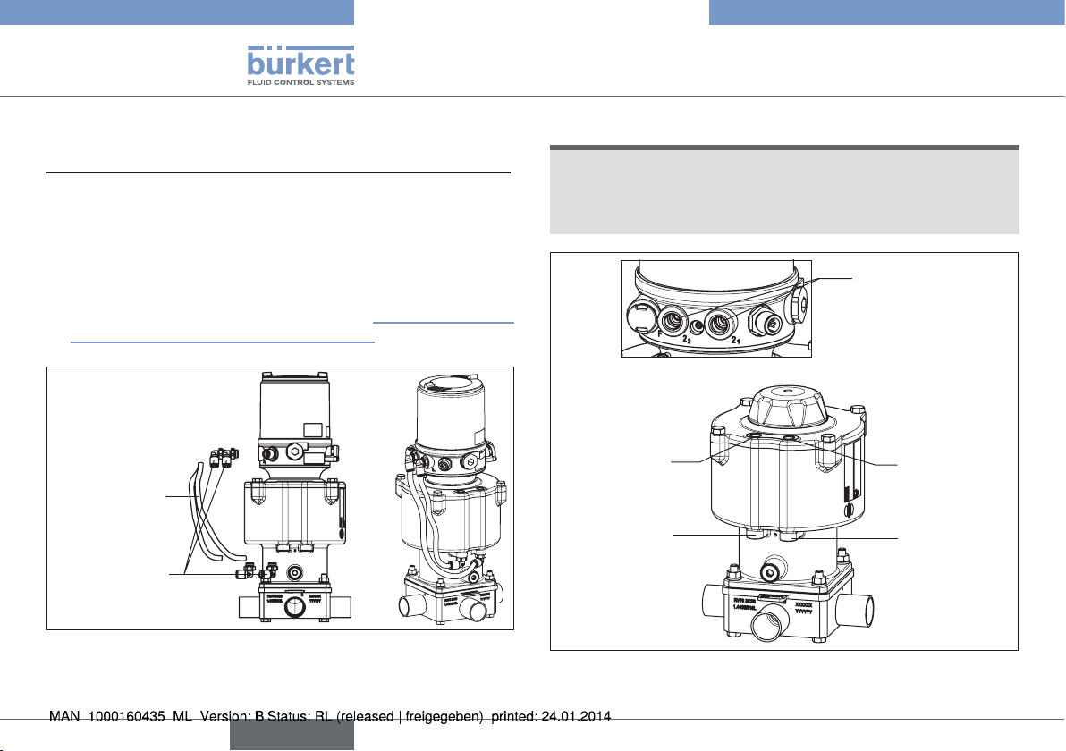
Device with circular plug-in connector:
→ Release the circular plug.
Device with cable gland:
→ Release the cable gland.
→ Loosen the wires from the screw terminals.
Control head
Type 8686
Electrical
connection
Fastening
screw (2x)
Pneumatic
connection
Actuator
Pneumatic connection
with actuator
Feedback head
Type 8685
Fastening screw (2x)
Actuator
Fig. 35: Disassembly
English
43
Page 44

Type 8685 / 8686
Accessories
15 ACCESSORIES
Designation Order no.
Connecting cable M12 x 1, 8-pole 919061
Auxiliary tool for installing the transparent cap 674077
Tab. 17: Accessories
16 TRANSPORT, STORAGE,
PACKAGING
NOTE!
Transport damage.
Inadequately protected equipment may be damaged during
transportation.
▶ During transportation protect the device against moisture and dirt
in shock-resistant packaging.
▶ Prevent the temperature from exceeding or dropping below the
permitted storage temperature.
▶ Protect the electrical interfaces of the coil and the pneumatic
connections from damage by placing protective caps on them.
Incorrect storage may damage the device.
▶ Store the device in a dry and dust-free location.
▶ Storage temperature -20 – 65 °C.
Damage to the environment caused by device components
contaminated with media.
▶ Ensure the device and packaging are disposed of in an environ-
mentally sound manner.
▶ Observe applicable regulations relating to refuse disposal and
the environment.
44
English
Page 45

Typ 8685 / 8686
Inhaltsverzeichnis
1 DIE BEDIENUNGSANLEITUNG .........................................................47
1.1 Darstellungsmittel ....................................................................47
1.2 Begriffsdefinition ......................................................................47
2 BESTIMMUNGSGEMÄSSE VERWENDUNG................................48
2.1 Beschränkungen ......................................................................48
3 GRUNDLEGENDE SICHERHEITSHINWEISE .............................. 48
4 ALLGEMEINE HINWEISE ....................................................................... 50
4.1 Kontaktadresse ........................................................................50
4.2 Gewährleistung ........................................................................50
4.3 Informationen im Internet .......................................................50
5 SYSTEMBESCHREIBUNG .................................................................... 50
5.1 Vorgesehener Einsatzbereich ...............................................50
5.2 Allgemeine Beschreibung .....................................................50
5.3 Aufbau Rückmeldekopf Typ 8685 .......................................51
5.4 Aufbau Steuerkopf Typ 8686 ...............................................51
5.5 Aufbau Adaptionsset für Antrieb Typ 2036 .......................52
6 TECHNISCHE DATEN ............................................................................. 52
6.1 Konformität ................................................................................52
6.2 Normen ......................................................................................52
6.3 Betriebsbedingungen .............................................................52
6.4 Mechanische Daten ................................................................53
6.5 Typschild ..................................................................................53
6.6 Pneumatische Daten ..............................................................53
6.7 Elektrische Daten Rückmeldekopf Typ 8685 ...................54
6.8 Elektrische Daten Steuerkopf Typ 8686 ............................55
7 MONTAGE .....................................................................................................56
7.1 Sicherheitshinweise ................................................................56
7.2 Montage Typ 8685 / 8686 an den Antrieb Typ 2036 ....56
8 PNEUMATISCHE INSTALLATION ...................................................... 61
8.1 Sicherheitshinweise ................................................................. 61
8.2 Pneumatische Installation Rückmeldekopf Typ 8685 .....62
8.3 Pneumatische Installation Steuerkopf Typ 8686 .............62
9 ELEKTRISCHE INSTALLATION ........................................................... 63
9.1 Sicherheitshinweise ................................................................63
9.2 Gerätevariante 24 V DC ........................................................63
9.3 Gerätevariante AS-Interface .................................................69
10 BEDIENUNG UND ANZEIGE ............................................................... 73
10.1 Bedien- und Anzeigeelemente Rückmeldekopf
Typ 8685 ...................................................................................73
10.2 Bedien- und Anzeigeelemente Steuerkopf Typ 8686 ....75
10.3 Bedienung .................................................................................76
11 SICHERHEITSSTELLUNGEN .............................................................. 81
12 WARTUNG .....................................................................................................81
12.1 Sicherheitshinweise ................................................................81
12.2 Service am Zuluftfilter .............................................................82
13 STÖRUNGEN ............................................................................................... 83
deutsch
45
Page 46

14 AUSSERBETRIEBNAHME .....................................................................84
14.1 Sicherheitshinweise ................................................................84
14.2 Demontage ...............................................................................84
15 ZUBEHÖR .....................................................................................................86
16 TRANSPORT, LAGERUNG, VERPACKUNG ..................................86
Typ 8685 / 8686
46
deutsch
Page 47

Typ 8685 / 8686
Die Bedienungsanleitung
1 DIE BEDIENUNGSANLEITUNG
Die Bedienungsanleitung beschreibt den gesamten Lebenszyklus
des Geräts. Bewahren Sie diese Anleitung so auf, dass sie für jeden
Benutzer gut zugänglich ist und jedem neuen Eigentümer des Geräts
wieder zur Verfügung steht.
Die Bedienungsanleitung enthält wichtige Informationen zur
Sicherheit!
Das Nichtbeachten dieser Hinweise kann zu gefährlichen Situationen führen.
▶ Die Bedienungsanleitung muss gelesen und verstanden werden.
1.1 Darstellungsmittel
GEFAHR!
Warnt vor einer unmittelbaren Gefahr.
▶ Bei Nichtbeachtung sind Tod oder schwere Verletzungen die
Folge.
WARNUNG!
Warnt vor einer möglicherweise gefährlichen Situation.
▶ Bei Nichtbeachtung drohen schwere Verletzungen oder Tod.
VORSICHT!
Warnt vor einer möglichen Gefährdung.
▶ Nichtbeachtung kann mittelschwere oder leichte Verletzungen
zur Folge haben.
HINWEIS!
Warnt vor Sachschäden.
▶ Bei Nichtbeachtung kann das Gerät oder die Anlage beschädigt
werden.
bezeichnet wichtige Zusatzinformationen, Tipps und
Empfehlungen.
verweist auf Informationen in dieser Bedienungsanleitung
oder in anderen Dokumentationen.
▶ markiert eine Anweisung zur Gefahrenvermeidung.
→ markiert einen Arbeitsschritt, den Sie ausführen müssen.
1.2 Begriffsdefinition
Der in dieser Anleitung verwendeten Begriff „Gerät“ steht immer für
den Rückmeldekopf Typ 8685 und den Steuerkopf Typ 8686.
deutsch
47
Page 48

Typ 8685 / 8686
Bestimmungsgemäße Verwendung
2 BESTIMMUNGSGEMÄSSE
VERWENDUNG
Bei nicht bestimmungsgemäßer Verwendung des Rückmeldekopfs Typ 8685 und des Steuerkopfs Typ 8686 können
Gefahren für Personen, Anlagen in der Umgebung und die
Umwelt entstehen.
Das Gerät ist für den Anbau an pneumatische Antriebe von Prozessventilen zur Steuerung von Medien konzipiert.
▶ Gerät nicht der direkten Sonneneinstrahlung aussetzen.
▶ Für den Einsatz die in den Vertragsdokumenten und der Bedie-
nungsanleitung spezifizierten zulässigen Daten, Betriebs- und
Einsatzbedingungen beachten. Diese sind im Kapitel „6 Technische Daten“ beschrieben.
▶ Gerät nur in Verbindung mit von Bürkert empfohlenen bzw.
zugelassenen Fremdgeräten und -komponenten einsetzen.
▶ Angesichts der Vielzahl von Einsatz- und Verwendungsfällen,
muss vor dem Einbau geprüft und erforderlichenfalls getestet
werden, ob der Rückmeldekopf bzw. der Steuerkopf für den
konkreten Einsatzfall geeignet ist.
▶ Voraussetzungen für den sicheren und einwandfreien Betrieb
sind sachgemäßer Transport, sachgemäße Lagerung und Installation sowie sorgfältige Bedienung und Instandhaltung.
▶ Gerät nur bestimmungsgemäß verwenden.
2.1 Beschränkungen
Beachten Sie bei der Ausfuhr des Systems/Geräts gegebenenfalls
bestehende Beschränkungen.
3 GRUNDLEGENDE
SICHERHEITSHINWEISE
Diese Sicherheitshinweise berücksichtigen keine
• Zufälligkeiten und Ereignisse, die bei Montage, Betrieb und Wartung
der Geräte auftreten können.
• ortsbezogenen Sicherheitsbestimmungen, für deren Einhaltung, auch
in Bezug auf das Montagepersonal, der Betreiber verantwortlich ist.
Verletzungsgefahr durch hohen Druck in Anlage/Gerät.
▶ Vor Arbeiten an Anlage oder Gerät, den Druck abschalten und
Leitungen entlüften/entleeren.
Gefahr durch Stromschlag.
▶ Vor Eingriffen in das Gerät oder die Anlage, Spannung abschal-
ten und vor Wiedereinschalten sichern.
▶ Die geltenden Unfallverhütungs- und Sicherheitsbestimmungen
für elektrische Geräte beachten.
48
deutsch
Page 49

Typ 8685 / 8686
Grundlegende Sicherheitshinweise
Allgemeine Gefahrensituationen.
Zum Schutz vor Verletzungen ist zu beachten:
• Rückmeldekopf Typ 8685 und Steuerkopf Typ 8686 nicht in
explosionsgefährdeten Bereichen einsetzen.
▶ Dass die Anlage nicht unbeabsichtigt betätigt werden kann.
▶ Installations- und Instandhaltungsarbeiten dürfen nur von auto-
risiertem Fachpersonal mit geeignetem Werkzeug ausgeführt
werden.
▶ Nach einer Unterbrechung der elektrischen oder pneumatischen
Versorgung ist ein definierter oder kontrollierter Wiederanlauf des
Prozesses zu gewährleisten.
▶ Das Gerät darf nur in einwandfreiem Zustand und unter Beach-
tung der Bedienungsanleitung betrieben werden.
▶ Für die Einsatzplanung und den Betrieb des Geräts müssen die
allgemeinen Regeln der Technik eingehalten werden.
Zum Schutz vor Sachschäden am Gerät ist zu beachten:
▶ In den Steuerluftanschluss bei Typ 8686 keine aggressiven oder
brennbaren Medien einspeisen.
▶ In den Steuerluftanschluss bei Typ 8686 keine Flüssigkeiten
einspeisen.
▶ Gehäuse nicht mechanisch belasten (z. B. durch Ablage von
Gegenständen oder als Trittstufe).
▶ Keine Veränderungen an den Gerätegehäusen vornehmen.
HINWEIS!
Elektrostatisch gefährdete Bauelemente / Baugruppen.
Das Gerät enthält elektronische Bauelemente, die gegen elektrostatische Entladung (ESD) empfindlich reagieren. Berührung mit elektrostatisch aufgeladenen Personen oder Gegenständen gefährdet
diese Bauelemente. Im schlimmsten Fall werden sie sofort zerstört
oder fallen nach der Inbetriebnahme aus.
▶ Beachten Sie die Anforderungen nach EN 61340-5-1, um die
Möglichkeit eines Schadens durch schlagartige elektrostatische
Entladung zu minimieren bzw. zu vermeiden.
▶ Achten Sie ebenso darauf, dass Sie elektronische Bauelemente
nicht bei anliegender Versorgungsspannung berühren.
deutsch
49
Page 50

Typ 8685 / 8686
Allgemeine Hinweise
4 ALLGEMEINE HINWEISE
4.1 Kontaktadresse
Deutschland
Bürkert Fluid Control Systems
Sales Center
Christian-Bürkert-Str. 13-17
D-74653 Ingelfingen
Tel. + 49 (0) 7940 - 10 91 111
Fax + 49 (0) 7940 - 10 91 448
E-mail: info@de.buerkert.com
International
Die Kontaktadressen finden Sie auf den letzten Seiten der
gedruckten Bedienungsanleitung.
Außerdem im Internet unter: www.burkert.com
4.2 Gewährleistung
Voraussetzung für die Gewährleistung ist der bestimmungsgemäße
Gebrauch des Rückmeldekopfs und des Steuerkopfs unter Beachtung
der spezifizierten Einsatzbedingungen.
4.3 Informationen im Internet
Bedienungsanleitungen und Datenblätter zum Typ 8685 und Typ 8686
finden Sie im Internet unter:
www.buerkert.de
5 SYSTEMBESCHREIBUNG
5.1 Vorgesehener Einsatzbereich
Der Rückmeldekopf Typ 8685 und der Steuerkopf Typ 8686 sind
für den Anbau an pneumatische Antriebe der Ventile Typ 2036 zur
Steuerung von Medien vorgesehen.
5.2 Allgemeine Beschreibung
Der Rückmeldekopf Typ 8685 und der Steuerkopf Typ 8686 sind
ausschließlich für den integrierten Anbau an einen Antrieb des
Membranventils Typs 2036 in den Baugrößen RV50, RV70, RV110
vorgesehen.
Die Anpassung der Antriebsgröße erfolgt mittels DIP-Schaltern.
Die Erfassung der Ventilstellung wird über einen Permanentmag-
neten auf der Spindelverlängerung vorgenommen. Bei der Hubbewegung wird die Spindelverlängerung an jeweils einem Reedsensor
(untere/obere Endstellung) entlang geführt.
Neben der elektrischen Stellungsrückmeldung wird der Gerätestatus
an dem Rückmeldekopf und Steuerkopf durch farbige LEDs optisch
dargestellt. Beim Steuerkopf wird der Status der integrierten Steuerventile ebenfalls durch LEDs angezeigt.
Bei der Variante mit AS-Interface Kommunikation sind zusätzlich
noch Busstatus LEDs aktiv.
50
deutsch
Page 51

Typ 8685 / 8686
Systembeschreibung
5.3 Aufbau Rückmeldekopf Typ 8685
Ansicht ohne
Klarsichthaube:
Elektrischer Anschluss
Kabelverschraubung M12 x 1,5
oder Rundsteckverbinder M12 x 1
Bild 1: Aufbau Rückmeldekopf Typ 8685
LEDs Status
AS-Interface
LEDs Status Antrieb
AUF/ZU (Endstellung)
Schiebeschalter
Farbauswahl
Endstellung
DIP-Schalter
Auswahl RV50/70/110
Druckbegrenzungsventil
(zum Schutz vor zu
hohem Innendruck im
Fehlerfall)
5.4 Aufbau Steuerkopf Typ 8686
Ansicht ohne Klarsichthaube und Gehäusemantel:
Blindverschraubung
M16 x 1,5
Elektrischer Anschluss
Kabelverschraubung M12 x 1,5
oder Rundsteckverbinder M12 x 1
LED Status Steuerventil
Schiebeschalter
Farbauswahl Endstellung
Schiebeschalter
Steuerventil
(Serviceschalter)
DIP-Schalter
Auswahl RV50/70/110
LEDs Status Antrieb
AUF/ZU (Endstellung)
LEDs Status
AS-Interface
Steuerluftanschluss
(Beschriftung: 1)
Abluftanschluss
(Beschriftung: 3)
Druckbegrenzungsventil
(zum Schutz vor zu
hohem Innendruck im
Fehlerfall)
Bild 2: Aufbau Steuerkopf Typ 8686
deutsch
51
Page 52

Typ 8685 / 8686
Technische Daten
5.5 Aufbau Adaptionsset für Antrieb
Typ 2036
2
9
8
Bild 3: Adaptionset für Typ 2036
Pos Menge Bezeichnung
1 1 Adaptionsgehäuse Robolux
2 6 Je 2 Stk. Schaltspindel RV50, RV70, RV110 kpl.
3 1 O-Ring 52 x 3 EPDM 75
4 1 Formdichtung
5 2 Zylinderschraube M6 x 12 A2 DIN 912
6 2 Zylinderschraube M4 mit Schaft
7 2 O-Ring 3,5 x 1,5 EPDM 70
8 2 Schlauch 280 mm
9 4 Winkelanschuss G1/8 SL6 Legris
Tab. 1: Stückliste Adaptionsset
5
4
1
7
6
3
6 TECHNISCHE DATEN
6.1 Konformität
Der Rückmeldekopf Typ 8685 und der Steuerkopf Typ 8686 sind konform
zu den EG-Richtlinien entsprechend der EG-Konformitätserklärung.
6.2 Normen
Die angewandten Normen, mit denen die Konformität mit den EG-Richtlinien nachgewiesen wird, sind in der EG-Baumusterprüfbescheinigung
und/oder der EG-Konformitätserklärung nachzulesen.
6.3 Betriebsbedingungen
WARNUNG!
Sonneneinstrahlung und Temperaturschwankungen können
Fehlfunktionen oder Undichtheiten bewirken.
▶ Das Gerät bei Einsatz im Außenbereich nicht ungeschützt den
Witterungsverhältnissen aussetzen.
▶ Darauf achten, dass die zulässige Umgebungstemperatur nicht
über- oder unterschritten wird.
Umgebungstemperatur 0 ... +55 °C
Schutzart IP65 / IP67 nach EN 60529 (nur bei korrekt ange
schlossenem Kabel bzw. Stecker und Buchsen und
bei Beachtung des Abluftkonzepts im Kapitel „8.3
Pneumatische Installation Steuerkopf Typ 8686“.
52
deutsch
Page 53

Typ 8685 / 8686
Technische Daten
6.4 Mechanische Daten
Abmessungen siehe Datenblatt
Gehäusematerial PPS, PC, VA
Dichtungsmaterial außen EPDM
innen NBR
Hubbereich Ventilspindel Antriebsgröße RV50 6 mm
Antriebsgröße RV70 9,5 mm
Antriebsgröße RV110 13,5 mm
6.5 Typschild
Beispiel:
Betriebsspannung / Ansteuerung
bzw. AS-Interface Profil
Typ
8686 AS-i S-7.A.E
2x single pilot 3,0
Pmax 7bar
Tamb 0 ... +55°C
Ser.-Nr. 001000
00XXXXXX
D-74653 Ingelfingen
Identnummer
W14UN
CE
Steuerfunktion
- Steuerventil
Max. Betriebsdruck
Umgebungstemperatur
Seriennummer
CE-Zeichen
Bar-Code
6.6 Pneumatische Daten
Steuermedium neutrale Gase, Luft
Qualitätsklassen nach DIN ISO 8573-1
Staubgehalt Klasse 5 max. Teilchengröße 40 µm,
max. Teilchendichte 10 mg/m³
Wassergehalt Klasse 3 max. Drucktaupunkt - 20 °C oder
min. 10 °C unterhalb der
niedrigsten Betriebstemperatur
Ölgehalt Klasse 5 max. 25 mg/m³
Temperaturbereich
Steuermedium -10 ... + 50 °C
Druckbereich
Steuermedium 6 ... 7 bar
(nähere Angaben siehe Bedienungsanleitung Typ 2036 und
Kapitel „8.3 Pneumatische Installation
Steuerkopf Typ 8686“)
Luftleistung Steuerventil 250 l
Anschlüsse Schlauchsteckverbinder Ø 6 mm / 1/4“
/ min (für Be- und Entlüftung)
N
(QNn- Wert nach Definition bei Druckabfall
von 7 auf 6 bar absolut)
Muffenanschluss G1/8
Bild 4: Typschild Beispiel
deutsch
53
Page 54

Typ 8685 / 8686
Technische Daten
6.7 Elektrische Daten
Rückmeldekopf Typ 8685
6.7.1 Elektrische Daten ohne
Busansteuerung 24 V DC
Anschlüsse Kabelverschraubung M12 x 1,5, SW15
(Klemmbereich 3 ... 6,5 mm)
mit Schraubklemmen
(Nennquerschnitt 1,0 mm²,
max. Leitungsquerschnitt 0,25 mm²)
Betriebsspannung 24 V DC ± 10 %
- max. Restwelligkeit 10 %
Ausgang max. 100 mA je Ausgang /
kurzschlussfest
Anzeige max. 20 mA
(2 Endstellungen
= 2 LEDs)
6.7.2 Elektrische Daten mit
Busansteuerung AS-Interface
Anschlüsse Abgesetztes 975 mm AS-Interface
Kabel mit Rundsteckverbinder
(M12 x 1, 4-polig)
Betriebsspannung 29,5 V ... 31,6 V DC
(gemäß Spezifikation)
max. Stromaufnahme 35 mA
54
deutsch
Page 55

Typ 8685 / 8686
Technische Daten
6.8 Elektrische Daten
Steuerkopf Typ 8686
6.8.1 Elektrische Daten ohne
Busansteuerung 24 V DC
Anschlüsse Kabelverschraubung M12 x 1,5, SW15
(Klemmbereich 3 ... 6,5 mm) mit Schraubklemmen
(Nennquerschnitt 1,0 mm²,
max. Leitungsquerschnitt 0,25 mm²)
Rundsteckverbinder (M12 x 1, 8-polig)
Steuerventil
Betriebsspannung 24 V DC ± 10 %
- max. Restwelligkeit 10 %
Leistungsaufnahme 2 x 0,8 W
Ausgang max. 100 mA je Ausgang /
kurzschlussfest
Anzeige max. 20 mA
(2 Endstellungen = 2 LEDs)
Servicefall:
Stromaufnahme 90 mA
(2 Endstellungen + 2 Ventile /
Serviceschalter an)
6.8.2 Elektrische Daten mit
Busansteuerung AS-Interface
Anschlüsse Abgesetztes 975 mm AS-Interface
Kabel mit Rundsteckverbinder (M12 x
1, 4-polig)
Betriebsspannung 29,5 V ... 31,6 V DC
(gemäß Spezifikation)
Ausgänge
Max. Schaltleistung 2 x 0,8 W über AS-Interface
Watchdogfunktion integriert
Max. Stromaufnahme 120 mA
(2 Ventil im Anzug +
2 Endstellungen)
Servicefall:
Stromaufnahme 105 mA
(2 Endstellungen
+ 2 Ventile /
Serviceschalter an)
deutsch
55
Page 56

Typ 8685 / 8686
Montage
7 MONTAGE
7.1 Sicherheitshinweise
GEFAHR!
Verletzungsgefahr durch hohen Druck in Anlage/Gerät.
▶ Vor Arbeiten an Anlage oder Gerät, den Druck abschalten und
Leitungen entlüften/entleeren.
Gefahr durch Stromschlag.
▶ Vor Eingriffen in das Gerät oder die Anlage, Spannung abschal-
ten und vor Wiedereinschalten sichern.
▶ Die geltenden Unfallverhütungs- und Sicherheitsbestimmungen
für elektrische Geräte beachten.
WARNUNG!
Verletzungsgefahr bei unsachgemäßer Montage.
▶ Die Montage darf nur autorisiertes Fachpersonal mit geeigne-
tem Werkzeug durchführen.
Verletzungsgefahr durch ungewolltes Einschalten der Anlage
und unkontrollierten Wiederanlauf.
▶ Anlage vor unbeabsichtigtem Betätigen sichern.
▶ Nach der Montage einen kontrollierten Wiederanlauf
gewährleisten.
7.2 Montage Typ 8685 / 8686 an den
Antrieb Typ 2036
Für die Montage an den Antrieb von Typ 2036 wird ein Adaptionsset
benötigt.
Das Adaptionsset (siehe „Bild 3“ auf Seite 52) beinhaltet ein Adaptionsgehäuse, eine Formdichtung, drei O-Ringe, vier Zylinderschrauben
und drei Schaltspindelpaare. Es gibt für Rückmeldekopf und Steuerkopf
unterschiedliche Adaptionssets. Innerhalb eines Adaptionssets gibt es
aufgrund der unterschiedlichen Arbeitshübe der Antriebsgrößen RV50,
RV70 und RV110 unterschiedliche Spindellängen.
Schaltspindeln Typ 8685
RV110 RV70
RV50
Antriebsgrößenkennzeichnung
Schaltspindeln Typ 8686
RV110 RV70
RV50
Kappe
56
Bild 5: Kennzeichnung Schaltspindel
deutsch
Page 57

Typ 8685 / 8686
Montage
Bezeichnung Bestell-Nr.
Adaptionsset für Typ 8685 684267
Adaptionsset für Typ 8686 684268
Tab. 2: Adapationssets
Vorgehensweise:
Schritt 1: Montage Adaptionsgehäuse auf den Antrieb
→ Klarsichthaube am Antrieb abschrauben.
→ O-Ring 52 x 3 in das Profil auf der Unterseite des Adaptionsge-
häuses setzen.
→ Adaptionsgehäuse unter Beachtung der Codierzapfen auf den
Antrieb aufsetzen.
→ Adaptionsgehäuse mit den zwei Zylinderschrauben M6 x 12 am
Antrieb festschrauben.
Zylinderschrauben M6 x 12
Adaptionsgehäuse
O-Ring 52 x 3
Codierzapfen
Antrieb
Bild 6: Montage Adaptionsgehäuse
HINWEIS!
Die Verwendung einer nicht passenden Schaltspindel führt
zu irreparablen Zerstörung des Rückmeldekopfs bzw. Steuerkopfs und des Antriebs.
▶ Nur die zur Antriebsgröße passenden Schaltspindeln verwen-
den. Die entsprechende Antriebsgrößenkennzeichnung (RV50,
RV70, RV110) für die Schaltspindeln sind auf der Stirnfläche
der PVC- Kappe eingeprägt (siehe „Bild 5“).
→ Die zur Antriebsgröße passende Schaltspindel auswählen (siehe
„Bild 5: Kennzeichnung Schaltspindel“).
→ Die zwei der Antriebsgröße zugehörigen Schaltspindeln am
Gewinde mit Loctite Schraubensicherung M290 benetzen.
HINWEIS!
Fehlfunktion bei Verwendung der falschen
Spindeldurchführung.
▶ Nur die zur Antriebsgröße passende Spindeldurchführung ver-
wenden (siehe „Bild 7“).
Spindeldurchführung
für Antriebsgröße
RV50
Spindeldurchführung
für Antriebsgröße
RV70 und RV110
Bild 7: Spindeldurchführung
deutsch
57
Page 58

Typ 8685 / 8686
Montage
HINWEIS!
Keine oder fehlerhafte Erkennung der Endstellungen.
▶ Position der Kappe auf der Schaltspindel nicht verändern.
▶ Loch ∅ 2,3 zum Befestigen der Schaltspindel verwenden.
→ Schaltspindeln durch die passenden Spindeldurchführungen
schieben. Dabei sind die äußeren Durchführungen für die Antriebsgröße RV70/110 und die innere Durchführung für die Antriebsgröße
RV50 vorgesehen (siehe „Bild 7“).
Kappe
Loch ∅ 2,3 zum
Einschrauben
der
Schaltspindel
Formdichtung
Bild 8: Montage Schaltspindeln und Formdichtung
→ Zwei Schaltspindeln mit geeignetem Werkzeug auf die Antriebs-
spindeln schrauben. Dazu ist an der Spindelseite ein Loch ∅ 2,3
angebracht (Drehmoment: 1,0 Nm ± 0,1 Nm).
→ Formdichtung auf das Adaptionsgehäuse setzen (kleinerer
Durchmesser zeigt nach oben).
Schritt 2: Montage Rückmeldekopf / Steuerkopf auf das
Adaptionsgehäuse
Erfolgt der elektrische Anschluss über Kabelverschraubung,
dann empfehlen wir die Adern an dieser Stelle anzuschließen,
da sonst der Rückmeldekopf / Steuerkopf zum elektrischen
Anschluss nochmals demontiert werden muss.
Elektrische Installation siehe: „9.2 Gerätevariante 24 V DC“
„Geräteanschluss Kabelverschraubung Typ 8685“
„Geräteanschluss Kabelverschraubung Typ 8686“
HINWEIS!
Fehlerhafte Erkennung der Endstellungen.
▶ Bei Antrieben mit Steuerfunktion B (SFB) muss vor dem Aufsetzen
des Rückmeldekopfs / Steuerkopfs auf das Adaptionsgehäuse die
untere Endstellung angefahren werden. Dazu ist der jeweilige Steuerluftanschluss des Antriebs („Bild 9“) mit Druck zu beaufschlagen.
▶ Auf die richtige Position des Rückmeldekopfs / Steuerkopfs zum
Antrieb achten: Blindstopfen oder Überdruckventil müssen auf
der Seite der pneumatischen Anschlüsse des Antriebs liegen
(siehe „Bild 9“).
→ Rückmeldekopf / Steuerkopf auf den Antrieb aufsetzen, dabei
beachten:
- Blindstopfen oder Überdruckventil müssen auf der Seite der
pneumatischen Anschlüsse des Antriebs liegen.
- Schaltspindeln müssen in die Aussparungen auf der Unterseite
des Rückmeldekopfs / Steuerkopfs hineinfinden. Dabei dürfen
die Kappen auf den Schaltspindeln nicht verschoben werden.
58
deutsch
Page 59

Typ 8686
Typ 8685 / 8686
Montage
Aussparung
Schaltspindel
Typ 8685
Blindstopfen
Montagebohrung des
Rückmeldekopfs / Steu-
erkopfs mit Vierkantmutter
des Adaptionsgehäuses
konzentrisch
O-Ring 3,5 x 1,5
Befestigungsschraube M4
Überdruckventil
Formdichtung
Anschluss
SFB
Anschluss
SFA
Typ 2036
Bild 9: Montage Rückmeldekopf / Steuerkopf
→ Rückmeldekopf / Steuerkopf soweit auf das Adaptionsgehäuse
schieben, dass an der Formdichtung kein Spalt mehr sichtbar ist.
Die Montagebohrung des Rückmeldekopfs / Steuerkopfs fluchtet
jetzt auf jeder Seite mit der Vierkantmutter des Adaptionsgehäuses.
Bild 10: Befestigung Rückmeldekopf / Steuerkopf
HINWEIS!
Durch ein zu hohes Drehmoment beim Einschrauben der
Befestigungsschraube oder durch fehlenden O-Ring kann die
Schutzart IP65 / IP67 nicht sichergestellt werden.
Pneumatische
Anschlüsse Antrieb
Die mechanische Kopplung ist beim Rückmeldekopf nach diesen
beiden Montageschritten bereits abgeschlossen. Beim Steuerkopf
muss zusätzlich noch der „Schritt 3: Montage Pneumatische Verbindung - Antrieb montieren“ vorgenommen werden.
▶ Die Befestigungsschraube darf nur mit einem maximalen Dreh-
moment von 0,5 Nm ± 0,1 Nm angezogen werden.
▶ Position des O-Rings prüfen.
→ Mit den zwei Befestigungsschrauben M4 und entsprechenden
O-Ringen den Rückmeldekopf / Steuerkopf auf dem Adaptionsgehäuse befestigen (Drehmoment : 0,5 Nm ± 0,1 Nm).
deutsch
59
Page 60

Typ 8685 / 8686
Montage
Nur Steuerkopf Typ 8686:
Schritt 3: Montage Pneumatische Verbindung - Antrieb
montieren
→ Schlauchsteckverbinder an den Steuerkopf und den Antrieb
schrauben.
→ Beiliegenden Schläuche (2 x 280 mm) entsprechend dem Gerä-
teaufbau ablängen.
→ Mit den im Zubehörsatz mitgelieferten Schläuchen die pneuma-
tische Verbindung zwischen Steuerkopf und Antrieb entsprechend
der Steuerfunktion (SF) mit nachfolgender „Tab. 3: Übersicht pneumatische Verbindungen für Antriebsvarianten“ herstellen.
Schläuche
Schlauchsteck-
verbinder
HINWEIS!
Beschädigung oder Funktionsausfall durch Eindringen von
Verschmutzung und Feuchtigkeit.
▶ Zur Einhaltung der Schutzart IP65 / IP67 an den nicht benötig-
ten Steuerluftanschluss (bei SFA und SFB) eine Abluftleitung in
den trockenen Bereich montieren.
Steuerluftausgänge
Steuerkopf
Antrieb 1
(links)
Steuerluft-
anschluss
2 (P2)
Steuerluft-
anschluss
1 (P1)
Antrieb 2
(rechts)
Steuerluftanschluss
4 (P4)
Steuerluftanschluss
3 (P3)
Bild 11: Montage der pneumatischen Verbindungen
60
Bild 12: Pneumatischer Anschluss
deutsch
Page 61

Typ 8685 / 8686
Pneumatische Installation
Typ 2036 Antrieb 1 Antrieb 2
SF Anschluss SF Anschluss
D11, D55
SFA/SFA
D12
SFA/SFB
D21
SFB/SFA
D22
SFB/SFB
SFA
SFA
SFB
SFB
2
P1
1
P2: Entlüftung
2
P1
1
P2: Entlüftung
2
P2
1
P1: Entlüftung
2
P2
1
P1: Entlüftung
SFA
SFB
SFA
SFB
2
P4: Entlüftung
2
P3: Entlüftung
2
P4: Entlüftung
2
P3: Entlüftung
P3
2
P4
2
P3
2
P4
2
Tab. 3: Übersicht pneumatische Verbindungen für
Antriebsvarianten
SFA, NC: Ventil in Ruhestellung geschlossen (durch Federkraft)
SFB, NO: Ventil in Ruhestellung offen (durch Federkraft)
Belegung der Steueranschlüsse siehe Installations- und
Maßzeichnung, die mit dem Ventil mitgeliefert wird oder in
der Bedienungsanleitung Typ 2036.
8 PNEUMATISCHE
INSTALLATION
Die Abmessungen des Rückmeldekopfs / Steuerkopfs und der verschiedenen Komplettgerätevarianten, bestehend aus Rückmeldekopf / Steuerkopf, Antrieb und Ventil, entnehmen Sie den jeweiligen Datenblättern.
8.1 Sicherheitshinweise
GEFAHR!
Verletzungsgefahr durch hohen Druck in Anlage/Gerät.
▶ Vor Arbeiten an Anlage oder Gerät, den Druck abschalten und
Leitungen entlüften/entleeren.
Gefahr durch Stromschlag.
▶ Vor Eingriffen in das Gerät oder die Anlage, Spannung abschal-
ten und vor Wiedereinschalten sichern.
▶ Die geltenden Unfallverhütungs- und Sicherheitsbestimmungen
für elektrische Geräte beachten.
WARNUNG!
Verletzungsgefahr bei unsachgemäßer Installation.
▶ Die Installation darf nur autorisiertes Fachpersonal mit geeigne-
tem Werkzeug durchführen.
Verletzungsgefahr durch ungewolltes Einschalten der Anlage
und unkontrollierten Wiederanlauf.
▶ Anlage vor unbeabsichtigtem Betätigen sichern.
▶ Nach der Installation einen kontrollierten Wiederanlauf gewährleisten.
deutsch
61
Page 62

Typ 8685 / 8686
Pneumatische Installation
8.2 Pneumatische Installation
Rückmeldekopf Typ 8685
Der Rückmeldekopf benötigt keine Steuerluftversorgung.
Die Beschreibung der pneumatischen Installation des Antriebs
befindet sich in der Bedienungsanleitung des Ventils.
8.3 Pneumatische Installation
Steuerkopf Typ 8686
GEFAHR!
Verletzungsgefahr durch hohen Druck in Anlage/Gerät.
▶ Vor Arbeiten an Anlage oder Gerät, den Druck abschalten und
Leitungen entlüften/entleeren.
Vorgehensweise:
→ Steuermedium an den Steuerluftanschluss (1) anschließen
(6 ... 7 bar; Instrumentenluft, öl-, wasser- und staubfrei).
→ Abluftleitung oder einen Schalldämpfer an den Abluftanschluss
(3) montieren (siehe „Bild 13: Pneumatischer Anschluss Typ
8686“).
Wichtiger Hinweis zur einwandfreien Funktion des Geräts:
▶ Durch die Installation darf sich kein Rückdruck aufbauen.
▶ Für den Anschluss einen Schlauch mit ausreichendem
Querschnitt wählen.
▶ Die Abluftleitung muss so konzipiert sein, dass kein Wasser
oder sonstige Flüssigkeit durch den Abluftanschluss (3) in
das Gerät gelangen kann.
Abluftanschluss
Beschriftung: 3
Steuerluftanschluss
Beschriftung: 1
Bild 13: Pneumatischer Anschluss Typ 8686
Achtung (Abluftkonzept): Für die Einhaltung der Schutzart
IP65 / IP67 muss eine Abluftleitung in den trockenen
Bereich montiert werden.
Den anliegenden Steuerdruck unbedingt mindestens 0,5 ...
1 bar über dem Druck halten, der notwendig ist, den Antrieb
in seine Endstellung zu bringen.
62
deutsch
Page 63

Typ 8685 / 8686
Elektrische Installation
9 ELEKTRISCHE INSTALLATION
9.1 Sicherheitshinweise
GEFAHR!
Gefahr durch Stromschlag.
▶ Vor Eingriffen in das Gerät oder die Anlage, Spannung abschal-
ten und vor Wiedereinschalten sichern.
▶ Die geltenden Unfallverhütungs- und Sicherheitsbestimmungen
für elektrische Geräte beachten.
WARNUNG!
Verletzungsgefahr bei unsachgemäßer Installation.
▶ Die Installation darf nur autorisiertes Fachpersonal mit geeigne-
tem Werkzeug durchführen.
Verletzungsgefahr durch ungewolltes Einschalten der Anlage
und unkontrollierten Wiederanlauf.
▶ Anlage vor unbeabsichtigtem Betätigen sichern.
▶ Nach der Installation einen kontrollierten Wiederanlauf
gewährleisten.
9.2 Gerätevariante 24 V DC
9.2.1 Elektrische Installation
Rückmeldekopf Typ 8685
Geräteanschluss Kabelverschraubung Typ 8685
→ Für den elektrischen Anschluss mit Kabelverschraubung einen
Leitungsquerschnitt von 0,25 mm² verwenden.
Befestigungs-
schrauben
M4 (2x)
Schraubklemmen
Bild 14: Position Schraubklemmen Typ 8685
→ Befestigungsschrauben M4 lösen und den Rückmeldekopf nach
oben abziehen (nur bei bereits montiertem Rückmeldekopf).
→ Kabelverschraubung montieren, falls erforderlich (ca. 1,5 Nm).
→ Kabel durch die Kabelverschraubung führen.
deutsch
63
Page 64

Typ 8685 / 8686
Elektrische Installation
Top1
Bot1
Top2
Bot2
Bild 15: Bezeichnung auf Platine Typ 8685
Bezeichnung
auf Platine
24 V
GND
Top 1
Bot 1
Top 2
Bot 2
Belegung
Betriebsspannung + 24 V DC ± 10 %
Betriebsspannung - GND
Endstellung oben Top Antrieb 1
Endstellung unten Bot Antrieb 1
Endstellung oben Top Antrieb 2
Endstellung unten Bot Antrieb 2
1)
24 V / 0 V (max. 0,1 A)
GND (7)
24 V / 0 V (max. 0,1 A)
GND (7)
24 V / 0 V (max. 0,1 A)
GND (7)
24 V / 0 V (max. 0,1 A)
GND (7)
Tab. 4: Anschluss Kabelverschraubung Typ 8685
→ Adern anklemmen (siehe Anschlussbelegung in „Tab. 4“).
Antrieb 1
(links)
GND24V
Steuerluft-
anschluss
2 (P2)
Steuerluft-
anschluss
1 (P1)
Antrieb 2
(rechts)
Steuerluftanschluss
4 (P4)
Steuerluftanschluss
3 (P3)
Bild 16: Pneumatischer Anschluss
HINWEIS!
Beschädigung oder Funktionsausfall durch Eindringen von
Verschmutzung und Feuchtigkeit.
▶ Zur Sicherstellung der Schutzart IP65 / IP67 die Überwurfmut-
ter der Kabelverschraubung entsprechend der verwendeten
Kabelgröße festziehen (ca. 1,5 Nm).
→ Überwurfmutter der Kabelverschraubung festziehen (ca. 1,5 Nm).
1) Antriebszuordnung siehe „Bild 16“
64
deutsch
Page 65

Typ 8685 / 8686
Elektrische Installation
HINWEIS!
Fehlerhafte Erkennung der Endstellungen.
▶ Bei Antrieben mit Steuerfunktion B (SFB) muss vor dem Aufset-
zen des Rückmeldekopfs auf das Adaptionsgehäuse die untere
Endstellung angefahren werden. Dazu ist der jeweilige Steuerluftanschluss des Antriebs („Bild 9“) mit Druck zu beaufschlagen.
▶ Auf die richtige Position des Rückmeldekopfs zum Antrieb ach-
ten: Blindstopfen oder Überdruckventil müssen auf der Seite der
pneumatischen Anschlüsse des Antriebs liegen (siehe „Bild 9“).
→ Rückmeldekopf auf den Antrieb aufsetzen, dabei beachten:
- Blindstopfen oder Überdruckventil müssen auf der Seite der
pneumatischen Anschlüsse des Antriebs liegen.
- Die Schaltspindeln müssen in die Aussparungen auf der Unterseite des Rückmeldekopf hineinfinden. Dabei dürfen die Kappen
auf den Schaltspindeln nicht verschoben werden.
→ Rückmeldekopf soweit auf das Adaptionsgehäuse schieben, dass
an der Formdichtung kein Spalt mehr sichtbar ist. Die Montagebohrung des Rückmeldekopfs fluchtet jetzt auf jeder Seite mit der
Vierkantmutter des Adaptionsgehäuses.
HINWEIS!
Durch ein zu hohes Drehmoment beim Einschrauben der
Befestigungsschraube oder durch fehlenden O-Ring kann die
Schutzart IP65 / IP67 nicht sichergestellt werden.
▶ Die Befestigungsschraube darf nur mit einem maximalen Dreh-
moment von 0,5 Nm ± 0,1 Nm angezogen werden.
▶ Position des O-Rings prüfen.
→ Mit den zwei Befestigungsschrauben M4 und entsprechenden
O-Ringen den Rückmeldekopf auf dem Adaptionsgehäuse
befestigen (Drehmoment : 0,5 Nm ± 0,1 Nm).
Nach Anlegen der Betriebsspannung ist der Rückmeldekopf in
Betrieb.
→ Bevor das Gerät einsatzfähig ist müssen noch die Grundeinstel-
lungen (siehe Kapitel „10.3.1 Grundeinstellungen“) am Rückmeldekopf vorgenommen werden.
deutsch
65
Page 66

Typ 8685 / 8686
Elektrische Installation
9.2.2 Elektrische Installation Steuerkopf
Typ 8686
Geräteanschluss Rundsteckverbinder Typ 8686
→ Rundsteckverbinder des Steuerkopfs entsprechend der „Tab. 5“
anschließen.
6
7
8
Bild 17: Belegung Rundstecker (M12 x 1, 8-polig)
Nur gerade Kabelbuchse verwenden.
Antrieb 1
(links)
Steuerluft-
anschluss
2 (P2)
Steuerluft-
anschluss
1 (P1)
Bild 18: Pneumatischer Anschluss
5
4
3
1
2
Antrieb 2
(rechts)
Steuerluftanschluss
4 (P4)
Steuerluftanschluss
3 (P3)
Nach Anlegen der Betriebsspannung ist der Steuerkopf in Betrieb.
→ Bevor das Gerät einsatzfähig ist die Grundeinstellungen (siehe
Kapitel „10.3.1 Grundeinstellungen“) am Steuerkopf vornehmen.
Ader-
Pin
farb
weiß
1
braun
2
grün
3
gelb
4
grau
5
rosa
6
blau Betriebsspannung – GND
7
rot Betriebsspannung + 24 V DC ± 10%
8
Belegung
2)
Endstellung unten Bot Antrieb 2
Endstellung oben Top Antrieb 2
Endstellung unten Bot Antrieb 1
Endstellung oben Top Antrieb 1
Ventilansteuerung Y2
Antrieb 2 betätigt
Ventilansteuerung Y1
Antrieb 1 betätigt
Tab. 5: Anschluss Rundsteckverbinder Typ 8686
2) Die angegebenen Farben beziehen sich auf das als Zubehör erhältliche
Anschlusskabel (919061).
3) Antriebszuordnung siehe „Bild 18“.
3)
Äußere Beschaltung
1
2
3
4
24 V / 0 V (max. 0,1 A)
GND (7)
24 V / 0 V (max. 0,1 A)
GND (7)
24 V / 0 V (max. 0,1 A)
GND (7)
24 V / 0 V (max. 0,1 A)
GND (7)
high aktiv, zur Aktivierung
5
mit 24 V verbinden
high aktiv, zur Aktivierung
6
mit 24 V verbinden
7
8
66
deutsch
Page 67

Typ 8685 / 8686
Elektrische Installation
Geräteanschluss Kabelverschraubung Typ 8686
→ Für den elektrischen Anschluss mit Kabelverschraubung einen
Leitungsquerschnitt von 0,25 mm² verwenden.
Befestigungs-
schrauben
M4 (2x)
Kabelhalter
Schraubklemmen
Bild 19: Position Schraubklemmen Typ 8686
→ Befestigungsschrauben M4 lösen und den Steuerkopf nach
oben abziehen (nur bei bereits montiertem Steuerkopf).
→ Kabelverschraubung montieren, falls erforderlich (ca. 1,5 Nm).
24V
GND
Valve1
Valve2
Top1
Bot1
Top2
Bot2
Bild 20: Bezeichnung auf Platine Typ 8686
→ Kabel durch die Kabelverschraubung führen.
→ Adern anklemmen (siehe „Tab. 6“).
Bezeichnung
auf Platine
Bot2
Top2
Bot1
Top1
Valve2
Valve1
GND
24V
Belegung
Endstellung unten -
Bot Antrieb 2
Endstellung oben Top Antrieb 2
Endstellung unten -
Bot Antrieb 1
Endstellung oben Top Antrieb 1
Ventilansteuerung Y2
Antrieb 2 betätigt
Ventilansteuerung Y1
Antrieb 1 betätigt
Betriebsspannung - GND
Betriebsspannung + 24 V DC ± 10 %
Tab. 6: Anschluss Kabelverschraubung Typ 8686
4) Antriebszuordnung siehe „Bild 18“
4)
Äußere Beschaltung
24 V / 0 V (max. 0,1 A)
GND (7)
24 V / 0 V (max. 0,1 A)
GND (7)
24 V / 0 V (max. 0,1 A)
GND (7)
24 V / 0 V (max. 0,1 A)
GND (7)
high aktiv, zur Aktivierung
mit 24 V verbinden
high aktiv, zur Aktivierung
mit 24 V verbinden
deutsch
67
Page 68

Typ 8685 / 8686
Elektrische Installation
HINWEIS!
Funktionsausfall durch beschädigte Adern.
▶ Zum Freihalten der Spindelführungen, alle Adern durch die
Kabelhalter führen.
Beschädigung oder Funktionsausfall durch Eindringen von
Verschmutzung und Feuchtigkeit.
▶ Zur Sicherstellung der Schutzart IP65 / IP67 die Überwurfmut-
ter der Kabelverschraubung entsprechend der verwendeten
Kabelgröße festziehen (ca. 1,5 Nm).
→ Alle Adern durch die Kabelhalter führen.
→ Überwurfmutter der Kabelverschraubung festziehen (ca. 1,5 Nm).
HINWEIS!
Fehlerhafte Erkennung der Endstellungen.
▶ Bei Antrieben mit Steuerfunktion B (SFB) muss vor dem Aufsetzen
des Steuerkopfs auf das Adaptionsgehäuse die untere Endstellung
angefahren werden. Dazu ist der jeweilige Steuerluftanschluss des
Antriebs („Bild 9“) mit Druck zu beaufschlagen.
▶ Auf die richtige Position des Steuerkopfs zum Antrieb achten:
Blindstopfen oder Überdruckventil müssen auf der Seite der
pneumatischen Anschlüsse des Antriebs liegen (siehe „Bild 9“).
→ Steuerkopf auf den Antrieb aufsetzen, dabei beachten:
- Blindstopfen oder Überdruckventil müssen auf der Seite der
pneumatischen Anschlüsse des Antriebs liegen.
- Die Schaltspindeln müssen in die Aussparungen auf der Unterseite des Steuerkopfs hineinfinden. Dabei dürfen die Kappen auf
den Schaltspindeln nicht verschoben werden.
→ Steuerkopf soweit auf das Adaptionsgehäuse schieben, dass an
der Formdichtung kein Spalt mehr sichtbar ist. Die Montagebohrung
des Steuerkopfs fluchtet jetzt auf jeder Seite mit der Vierkantmutter
des Adaptionsgehäuses.
HINWEIS!
Durch ein zu hohes Drehmoment beim Einschrauben der
Befestigungsschraube oder durch fehlenden O-Ring kann die
Schutzart IP65 / IP67 nicht sichergestellt werden.
▶ Die Befestigungsschraube darf nur mit einem maximalen Dreh-
moment von 0,5 Nm ± 0,1 Nm angezogen werden.
▶ Position des O-Rings prüfen.
→ Mit den zwei Befestigungsschrauben M4 und entsprechenden
O-Ringen den Steuerkopf auf dem Adaptionsgehäuse befestigen
(Drehmoment : 0,5 Nm ± 0,1 Nm).
Nach Anlegen der Betriebsspannung ist der Steuerkopf in Betrieb.
→ Bevor das Gerät einsatzfähig ist müssen noch die Grundeinstel-
lungen (siehe Kapitel „10.3.1 Grundeinstellungen“) am Steuerkopf vorgenommen werden.
68
deutsch
Page 69

Typ 8685 / 8686
Elektrische Installation
9.3 Gerätevariante AS-Interface
9.3.1 Elektrische Installation
Rückmeldekopf und Steuerkopf
Der elektrische Anschluss von Rückmeldekopf und Steuerkopf
erfolgt über Multipolkabel (M12 Rundsteckverbinder) und Flachkableklemme. Der Rundstecker kann einfach mit der Flachkabelklemme
(siehe „Bild 21“) verbunden werden.
Schrauben
M12 Steckverbinder
Abgang
Anschlussbild des Rundsteckers M12
Die Ansicht zeigt das Bild von vorn auf die Stifte, die Lötanschlüsse
liegen dahinter.
Pin 4:
NC
Pin 1:
Bus +
Bild 22: Busanschluss
Pin Bezeichnung Belegung
Bus + Busleitung AS-Interface +
1
NC nicht belegt
2
Bus – Busleitung AS-Interface –
3
NC nicht belegt
4
Tab. 7: Pin-Belegung Rundsteckverbinder AS-Interface
Pin 3:
Bus –
Pin 2:
NC
Bild 21: Rückmeldekopf / Steuerkopf mit Multipolkabel und
Flachkabelklemme
deutsch
69
Page 70

Typ 8685 / 8686
Elektrische Installation
Handhabung der Flachkabelklemme
Am Multipolkabel befindet sich eine, mit M12 Steckverbinder Abgang
versehene, Flachkabelklemme für AS-Interface Formkabel. Die Flachkabelklemme realisiert die Kontaktierung des AS-Interface Formkabels
in Form einer Durchdringungstechnik, die eine Installation durch „Einklipsen“ des AS-Interface Formkabels ohne Schneiden und Abisolieren
ermöglicht.
Vorgehensweise:
→ Flachkabelklemme öffnen
(Schrauben lösen und Deckel abheben).
→ Formkabel schlüssig einlegen.
→ Flachkabelklemme wieder schließen.
→ Schrauben festziehen
Gewindeformende Schrauben durch kurzes Zurückdrehen (ca.
3/4 Umdrehung nach links) an der bestehenden Gewindebohrung ansetzen und einschrauben.
9.3.2 AS-Interface Anschaltung
AS-Interface (Aktor-Sensor-Interface) ist ein Feldbussystem, das
hauptsächlich zur Vernetzung von binären Sensoren und Aktoren
(Slaves) mit einer übergeordneten Steuerung (Master) dient.
Busleitung
Ungeschirmte Zweidrahtleitung (AS-Interface Leitung als ASInterface Formkabel), auf der sowohl Informationen (Daten) als auch
Energie (Versorgungsspannung der Aktoren und Sensoren) übertragen werden.
Netztopologie
In breiten Grenzen frei wählbar, d. h. es sind Stern,- Baum- und Liniennetze möglich. Weitere Details beschreibt die AS-Interface Spezifikation (Ausführung A/B-Slave konform zur Spezifikation Version 3.0
9.3.3 Technische Daten für AS-Interface
Platinen
Versorgung: über AS-Interface (29,5 V ... 31,6 V)
Ausgänge Steuerkopf: Ventil Y1 und Ventil Y2
mit jeweils max. 0,8 W,
Leistungsreduzierung nach ca. 100 ms
mit integrierter Watch-Dog-Funktion
Zertifizierung: Rückmeldekopf: Zertifikat Nr. 94701
nach Version 3.0
Steuerkopf: Zertifikat Nr. 94801
nach Version 3.0
9.3.4 Programmierdaten
Programmierdaten Rückmeldekopf Typ 8685
E/A-Konfiguration 0 hex
ID-Code A hex (Bitbelegung siehe unten)
Erweiterter ID-Code 1 7 hex
Erweiterter ID-Code 2 E hex
Profil S-0.A.E
Tab. 8: Programmierdaten Rückmeldekopf Typ 8685
70
deutsch
Page 71

Typ 8685 / 8686
Elektrische Installation
Bitbelegung
Datenbit
Eingänge
D0
D1
D2
D3
Datenbit
Ausgänge
Funktion Belegung
Endstellung oben Top Antrieb 1
Endstellung unten Bot Antrieb 1
Endstellung oben Top Antrieb 2
Endstellung unten Bot Antrieb 2
0 Top nicht erreicht
1 Top erreicht
0 Bot nicht erreicht
1 Bot erreicht
0 Top nicht erreicht
1 Top erreicht
0 Bot nicht erreicht
1 Bot erreicht
Funktion Belegung
5)
5)
D0 - nicht belegt
D1 - nicht belegt
D2 - nicht belegt
D3 - nicht belegt
Tab. 9: Bitbelegung AS-Interface Rückmeldekopf Typ 8685
Parameterbits ohne Funktion.
5) Antriebszuordnung siehe „Bild 23“
Programmierdaten Steuerkopf Typ 8686
E/A-Konfiguration 7 hex
ID-Code A hex (Bitbelegung siehe unten)
Erweiterter ID-Code 1 7 hex
Erweiterter ID-Code 2 E hex
Profil S-7.A.E
Tab. 10: Programmierdaten Steuerkopf Typ 8686
Antrieb 1
(links)
Steuerluft-
anschluss
2 (P2)
Steuerluft-
anschluss
1 (P1)
Antrieb 2
(rechts)
Steuerluftanschluss
4 (P4)
Steuerluftanschluss
3 (P3)
Bild 23: Pneumatischer Anschluss
deutsch
71
Page 72

Typ 8685 / 8686
Elektrische Installation
Bitbelegung
Datenbit
Eingänge
D0
D1
D2
D3
Datenbit
Ausgänge
D0 Steuerventil Y1
D1 Steuerventil Y2
Funktion Belegung
Endstellung oben Top Antrieb 1
Endstellung unten Bot Antrieb 1
Endstellung oben Top Antrieb 2
Endstellung unten Bot Antrieb 2
0 Top nicht erreicht
1 Top erreicht
0 Bot nicht erreicht
1 Bot erreicht
0 Top nicht erreicht
1 Top erreicht
0 Bot nicht erreicht
1 Bot erreicht
Funktion Belegung
0 Steuerventil OFF
1 Steuerventil ON
0 Steuerventil OFF
1 Steuerventil ON
D2 - nicht belegt
D3 - nicht belegt
Tab. 11: Bitbelegung AS-Interface Steuerkopf Typ 8686
Parameterbits ohne Funktion.
6) Antriebszuordnung siehe „Bild 24“
9.3.5 LED Zustandsanzeige AS-Interface
6)
6)
Status LED 1
(grün)
Status LED 2
(rot)
aus aus POWER OFF
kein Datenverkehr (abgelaufener
aus ein
Watch-Dog bei Slaveadresse
ungleich 0)
ein aus OK
blinkt ein Slaveadresse gleich 0
Tab. 12: LED Zustandsanzeige AS-Interface
Antrieb 1
(links)
Steuerluft-
anschluss
2 (P2)
Steuerluft-
anschluss
1 (P1)
Bild 24: Pneumatischer Anschluss
Antrieb 2
(rechts)
Steuerluftanschluss
4 (P4)
Steuerluftanschluss
3 (P3)
72
deutsch
Page 73

Typ 8685 / 8686
Bedienung und Anzeige
10 BEDIENUNG UND ANZEIGE
10.1 Bedien- und Anzeigeelemente
Rückmeldekopf Typ 8685
10.1.1 Gerätevariante 24 V DC
Die nachfolgend aufgeführten Positionen sind für Antrieb 1 und 2
getrennt ausgeführt.
Anzeigeelemente:
• Status Antrieb (Endstellung)
Die Anzeigeelemente sind in Form einer LED ausgeführt.
Bedienelemente:
• DIP-Schalter zur Auswahl der Antriebsgröße RV50, RV70, RV110
• Schiebeschalter zur Farbauswahl der Endstellung
Wird die Klarsichthaube abgeschraubt, sind die Hinweise in
„Schritt 4: Klarsichthaube / Gehäusemantel schließen“ auf
Seite 78 zu beachten.
Schiebeschalter
Farbauswahl Endstellung
Antrieb 1
LEDs
Status Antrieb 1
(Endstellung)
DIP-Schalter
Antrieb 1
Bild 25: Bedien- und Anzeigeelemente Rückmeldekopf 24 V DC
Schiebeschalter
Farbauswahl Endstellung
Antrieb 2
LEDs
Status Antrieb 2
(Endstellung)
DIP-Schalter
Antrieb 2
deutsch
73
Page 74

Typ 8685 / 8686
Bedienung und Anzeige
10.1.2 Gerätevariante AS-Interface
Abgesehen von dem AS-Interface Busstatus sind die nachfolgend
aufgeführten Positionen für Antrieb 1 und 2 getrennt ausgeführt.
Anzeigeelemente:
• AS-Interface Busstatus
• Status Antrieb (Endstellung)
Die Anzeigeelemente sind in Form einer LED ausgeführt.
Bedienelemente:
• DIP-Schalter zur Auswahl der Antriebsgröße RV50, RV70, RV110
• Schiebeschalter zur Farbauswahl der Endstellung
Wird die Klarsichthaube abgeschraubt, sind die Hinweise in
„Schritt 4: Klarsichthaube / Gehäusemantel schließen“ auf
Seite 78 zu beachten.
AS-Interface Busstatus
Schiebeschalter zur
Farbauswahl Endstellung
Antrieb 1
LEDs
Status Antrieb 1
(Endstellung)
DIP-Schalter
Antrieb 1
LEDs
Schiebeschalter zur
Farbauswahl Endstellung
Antrieb 2
LEDs
Status Antrieb 2
(Endstellung)
DIP-Schalter
Antrieb 2
74
Bild 26: Bedien- und Anzeigeelemente Rückmeldekopf
AS-Interface
deutsch
Page 75

Typ 8685 / 8686
Bedienung und Anzeige
10.2 Bedien- und Anzeigeelemente
Steuerkopf Typ 8686
Die nachfolgend aufgeführten Positionen sind für Antrieb 1 und 2
getrennt ausgeführt.
Die Gerätevariante 24 V DC und AS-Interface haben dieselbe
Anzeige- und Bedienplatine.
Die AS-Interface Busstatus LEDs sind bei der Gerätevariante 24 V
DC entsprechend inaktiv.
Anzeigeelemente:
• AS-Interface Busstatus
• Status Antrieb (Endstellung)
• Status Steuerventil
Die Anzeigeelemente sind in Form einer LED ausgeführt.
Bedienelemente:
• DIP-Schalter zur Auswahl der Antriebsgröße RV50, RV70, RV110
• Schiebeschalter zur Farbauswahl der Endstellung
• Schiebeschalter zur Direktansteuerung der Steuerventile
(Serviceschalter)
Wird die Klarsichthaube / der Gehäusemantel abgeschraubt, sind die Hinweise in „Schritt 4: Klarsichthaube /
Gehäusemantel schließen“ auf Seite 78 zu beachten.
LED Status Steuerventil
Antrieb 1
Schiebeschalter
(Serviceschalter)
Steuerventil Antrieb 1
DIP-Schalter
Antrieb 1
LEDs
Status Antrieb 1
(Endstellung)
Schiebeschalter
Farbauswahl Endstellung
Antrieb 1
AS-Interface Busstatus
Bild 27: Bedien- und Anzeigeelemente Steuerkopf
LED Status Steuerventil
Antrieb 2
Schiebeschalter
(Serviceschalter)
Steuerventil Antrieb 2
LEDs
Status Antrieb 2
(Endstellung)
Schiebeschalter
Farbauswahl Endstellung
Antrieb 2
LEDs
DIP-Schalter
Antrieb 2
deutsch
75
Page 76

Typ 8685 / 8686
Bedienung und Anzeige
10.3 Bedienung
10.3.1 Grundeinstellungen
Um die Funktion der Typen 8685 und 8686 zu gewährleisten,
müssen diese Grundeinstellungen vor der Inbetriebnahme im spannungslosen Zustand vorgenommen werden.
GEFAHR!
Gefahr durch Stromschlag.
▶ Vor Eingriffen in das Gerät oder die Anlage, Spannung abschal-
ten und vor Wiedereinschalten sichern.
▶ Die geltenden Unfallverhütungs- und Sicherheitsbestimmungen
für elektrische Geräte beachten.
→ Klarsichthaube abschrauben.
→ Schritte 1 bis 4 durchführen.
Schritt 1: Auswahl der Antriebsgröße
Die Bedienelemente sind jeweils für eine Antriebsseite ausgeführt.
Pro Antriebsseite nur ein DIP-Schalterelement entsprechend der Antriebsgröße (siehe Typschild des Antriebs)
aktiv schalten. Auf beiden Antriebsseiten muss eine einheitliche Antriebsgröße gewählt werden!
Fehleinstellungen der DIP-Schalter führen zu Fehlfunktionen
bzw. keinerlei Funktion der Endstellungsrückmeldung.
→ Durch Schieben eines DIP-Schalterelements in die „ON“
Position werden die Endstellungssensoren der gewählten
Antriebsgröße aktiviert.
Typ 8686
Typ 8685
RV110
RV70
RV50
ACTUATOR
Bild 28: Auswahl Antriebsgröße über DIP-Schalter
Schritt 2: Zuordnung der Endstellung LEDs ändern (Status
Antrieb)
Mit diesen Schiebeschaltern kann die Farbzuordnung der Endstellungen eingestellt werden. Für jede Farbe kann angegeben werden,
ob sie für TOP (obere Endstellung) oder Bot (untere Endstellung)
gelten soll.
Die Schiebeschalter für die Farbauswahl muss innerhalb
der Antriebskammer eindeutig gewählt werden, d. h. beide
Schalter oben oder beide Schalter unten.
Fehleinstellungen dieser Schalter führen zu einer optischen
Fehlinterpretation der Endstellungserkennung, die Endstellungserkennung ist jedoch korrekt.
ON
ON
1 2 3
76
deutsch
Page 77

Typ 8685 / 8686
Bedienung und Anzeige
Typ 8686
Typ 8685
Bild 29: Farbzuordnung Endstellungen über Schiebeschalter
Dabei gilt die Platinenbeschriftung bzw. nachfolgende Tabelle
Schalterstellung für eine
Antriebsseite
beide Schalter oben Endstellung Top gelb /
beide Schalter unten Endstellung Top grün /
Schalter oben/unten - ungültiger Zustand Schalter unten/oben - ungültiger Zustand -
Tab. 13: Farbzuordnung Endstellungen
Werkseitig ist folgende Funktion eingestellt:
Farbe Status Antrieb
grüne LED leuchtet untere Endstellung
gelbe LED leuchtet obere Endstellung
Tab. 14: Zuordnung der Status Antrieb LEDs (Endstellung)
LED Status Antrieb
Endstellung Bot grün
Endstellung Bot gelb
gn ye
Bot
Top
Top
Bot
Schritt 3: Referenzfahrt Spindeljustage
Um die Feinabstimmung der Spindel auf die Antriebsgröße vorzunehmen, müssen beide Spindeln zwingend von der unteren zur oberen
Endstellung gefahren werden.
Vorgehensweise Typ 8685:
Antrieb in Ausführung Steuerfunktion A (SFA) :
→ Unter maximalem Steuerdruck die Spindeln durch Ansteuerung
der Antriebskammern nach oben fahren.
→ Nach Erreichen der Endstellung (vorgewählte LED leuchtet), den
Steuerdruck abschalten. Die Spindel fährt auf die untere Endstellung. LED für die Endstellung Bot leuchtet mit der gewählten
Farbe.
Antrieb in Ausführung Steuerfunktion B (SFB):
→ Unter maximalem Steuerdruck die Spindeln durch Ansteuerung
der Antriebskammern nach unten fahren.
→ Nach Erreichen der Endstellung (vorgewählte LED leuchtet), den
Steuerdruck abschalten. Die Spindel fährt auf die obere Endstellung. Die jeweilige LED für die Endstellung leuchtet mit der
gewählten Farbe.
deutsch
77
Page 78

Typ 8685 / 8686
Bedienung und Anzeige
Vorgehensweise Typ 8686:
→ Unter maximalem Steuerdruck den Serviceschalter auf „On“
schalten. Die Spindel fährt in obere Endstellung.
→ Nach Erreichen der Endstellung (vorgewählte LED Status Antrieb
leuchtet), den Serviceschalter wieder auf „Off“ schalten. Die
Spindel fährt auf die Ausgangsstellung. Die jeweilige LED Status
Antrieb für die Endstellung leuchtet mit der gewählten Farbe.
Serviceschalter
Service
Off
On
Service
On
Off
LED Status Steuerventil
Bild 30: Spindeljustage Typ 8686
Schritt 4: Klarsichthaube / Gehäusemantel schließen
→ Korrekte Position der Dichtung in Klarsichthaube / im Gehäuse-
mantel prüfen (siehe „Bild 31“).
HINWEIS!
Beschädigung oder Funktionsausfall durch Eindringen von
Verschmutzung und Feuchtigkeit.
▶ Zur Einhaltung der Schutzart IP65 / IP67 die Klarsichthaube /
den Gehäusemantel bis auf Anschlag einschrauben.
→ Klarsichthaube / Gehäusemantel schließen (Hilfswerkzeug zur
Deckelmontage: 6740777)).
Klarsichthaube
Dichtung
Klarsichthaube
Typ 8685
Gehäusemantel
Dichtung
Gehäusemantel
Typ 8686
Bild 31: Position Dichtung Klarsichthaube / Gehäusemantel
Das Gerät ist jetzt konfiguriert und betriebsbereit!
7) Das Hilfswerkzeug zur Deckelmontage (674077) ist über Ihre Bürkert-
Vertriebsniederlassung erhältlich.
78
deutsch
Page 79

Typ 8685 / 8686
Bedienung und Anzeige
10.3.2 Ändern der Einstellungen
Vorgehensweise:
→ Durch Herausdrehen der Klarsichthaube werden die Schiebe-
schalter und DIP-Schalter zugänglich.
→ Auswahl der Antriebsgröße mit den DIP-Schaltern vornehmen. Auf
beiden Antriebsseiten muss eine einheitliche Antriebsgröße gewählt
werden (siehe Typschild des Ventils)!
→ Mit Hilfe der „Tab. 13: Farbzuordnung Endstellungen“ bzw. der
Beschriftung auf der Platine den LEDs Status Antrieb (Endstellung)
die gewünschte Farbe zuordnen.
→ Korrekte Position der Dichtung in Klarsichthaube / im Gehäuse-
mantel prüfen (siehe „Bild 31“).
HINWEIS!
Beschädigung oder Funktionsausfall durch Eindringen von
Verschmutzung und Feuchtigkeit.
▶ Zur Einhaltung der Schutzart IP65 / IP67 die Klarsichthaube /
den Gehäusemantel bis auf Anschlag einschrauben.
→ Klarsichthaube / Gehäusemantel schließen (Hilfswerkzeug zur
Deckelmontage: 6740778)).
8) Das Hilfswerkzeug zur Deckelmontage (674077) ist über Ihre Bürkert-
Vertriebsniederlassung erhältlich.
10.3.3 Manuelle Ansteuerung der Steuerventile beim Steuerkopf Typ 8686
Mit den Serviceschaltern können die Steuerventile geschalten
werden. Bei Steuerfunktion A wird die Spindel mit Schalterstellung
„On“ hochgefahren. Bei Steuerfunktion B wird die Spindel mit
Schalterstellung „On“ heruntergefahren.
Schiebeschalter
(Serviceschalter)
Steuerventil Antrieb 1
Service
On
Off
LED Status
Steuerventil Antrieb 1
Bild 32: Serviceschalter und Status LEDs Steuerventil (Typ 8686)
Vorgehensweise:
Die Spannung am Gerät ist zwingend erforderlich!
Schiebeschalter
(Serviceschalter)
Steuerventil Antrieb 2
Service
Off
On
LED Status
Steuerventil Antrieb 2
→ Durch Herausdrehen der Klarsichthaube werden die Service-
schalter zugänglich.
→ Mit den Serviceschaltern das jeweilige Steuerventil schalten.
→ Korrekte Position der Dichtung in Klarsichthaube / im Gehäuse-
mantel prüfen (siehe „Bild 31“).
deutsch
79
Page 80

Typ 8685 / 8686
Bedienung und Anzeige
HINWEIS!
Beschädigung oder Funktionsausfall durch Eindringen von
Verschmutzung und Feuchtigkeit.
▶ Zur Einhaltung der Schutzart IP65 / IP67 die Klarsichthaube /
den Gehäusemantel bis auf Anschlag einschrauben.
→ Klarsichthaube / Gehäusemantel schließen (Hilfswerkzeug zur
Deckelmontage: 6740779)).
Vorgehensweise beim Austausch der Membran bei Typ 2036
Die Spannung am Gerät ist zwingend erforderlich!
→ Durch Herausdrehen der Klarsichthaube werden die Service-
schalter zugänglich.
→ Membranaustausch nach der Vorgehensbeschreibung in der
Bedienungsanleitung Typ 2036 durchführen.
→ Nach dem Membranaustausch muss eine Referenzfahrt Spindel-
justage (siehe „10.3.1 Grundeinstellungen“, Schritt 3 ) vorgenommen werden.
→ Korrekte Position der Dichtung in Klarsichthaube / im Gehäuse-
mantel prüfen (siehe „Bild 33“).
HINWEIS!
Beschädigung oder Funktionsausfall durch Eindringen von
Verschmutzung und Feuchtigkeit.
▶ Zur Einhaltung der Schutzart IP65 / IP67 die Klarsichthaube /
den Gehäusemantel bis auf Anschlag einschrauben.
→ Klarsichthaube / Gehäusemantel schließen (Hilfswerkzeug zur
Deckelmontage: 6740779)).
Gehäusemantel
Dichtung
Gehäusemantel
Typ 8686
Bild 33: Position Dichtung Gehäusemantel
9) Das Hilfswerkzeug zur Deckelmontage (674077) ist über Ihre Bürkert-
Vertriebsniederlassung erhältlich.
80
deutsch
Page 81

Typ 8685 / 8686
Sicherheitsstellungen
11 SICHERHEITSSTELLUNGEN
Sicherheitsstellungen nach Ausfall der elektrischen bzw. pneumatischen Hilfsenergie:
Sicherheitsstellungen nach
Antriebssart Bezeichnung
einfach-
wirkend
up
down
up
down
Tab. 15: Sicherheitsstellungen
Steuer-
funktion A
einfachwirkend
Steuer-
funktion B
Ausfall der Hilfsenergie
elektrisch pneumatisch
down down
up up
12 WARTUNG
12.1 Sicherheitshinweise
GEFAHR!
Verletzungsgefahr durch hohen Druck in Anlage/Gerät.
▶ Vor Arbeiten an Anlage oder Gerät, den Druck abschalten und
Leitungen entlüften/entleeren.
Gefahr durch Stromschlag.
▶ Vor Eingriffen in das Gerät oder die Anlage, Spannung abschal-
ten und vor Wiedereinschalten sichern.
▶ Die geltenden Unfallverhütungs- und Sicherheitsbestimmungen
für elektrische Geräte beachten.
WARNUNG!
Verletzungsgefahr bei unsachgemäßen Wartungsarbeiten.
▶ Die Wartung darf nur autorisiertes Fachpersonal mit geeignetem
Werkzeug durchführen.
Verletzungsgefahr durch ungewolltes Einschalten der Anlage
und unkontrollierten Wiederanlauf.
▶ Anlage vor unbeabsichtigtem Betätigen sichern.
▶ Nach der Wartung einen kontrollierten Wiederanlauf
gewährleisten.
deutsch
81
Page 82

Typ 8685 / 8686
Wartung
12.2 Service am Zuluftfilter
GEFAHR!
Verletzungsgefahr durch hohen Druck in Anlage/Gerät.
▶ Vor Arbeiten an Anlage oder Gerät, den Druck abschalten und
Leitungen entlüften/entleeren.
Zum Schutz der internen Steuerventile und des Antriebs wird die
Steuerluft gefiltert.
Die Durchflussrichtung des Zuluftfilters im eingebauten Zustand ist
von innen nach außen durch das Siebgewebe.
Schnellsteckverbinder
O-Ring
Zuluftfilter
Bild 34: Service am Zuluftfilter
Vorgehensweise:
→ Schnellsteckverbinder durch Eindrücken des Halteelements
entriegeln und Zuluftfilter herausziehen (eventuell unter Zuhilfenahme eines geeigneten Werkzeugs zwischen den Aussparungen im Kopf des Filters).
→ Filter reinigen oder falls nötig Filter auswechseln.
→ Innenliegenden O-Ring prüfen und gegebenenfalls säubern.
→ Zuluftfilter bis zum Anschlag in die Schnellsteckverbindung
stecken.
GEFAHR!
Verletzungsgefahr durch unsachgemäße Montage.
▶ Auf richtige Montage des Zuluftfilters achten.
→ Sicheren Sitz des Zuluftfilters prüfen.
82
deutsch
Page 83

Typ 8685 / 8686
Wartung
13 STÖRUNGEN
Störung Ursache und Beseitigung
Keine
Erkennung der
Endstellung
Keine oder nicht ausreichende
Betriebsspannung
→ Elektrischer Anschluss und Betriebs-
spannung prüfen
Falsche Größe der Schaltspindeln aus dem
Adaptionsset
→ Schaltspindeln tauschen
Falsche Spindeldurchführung bei der Spindelmontage ausgewählt
→ Schaltspindel durch passende Spindel-
durchführung schieben
Falsche Antriebsgröße an den DIP-Schaltern
ausgewählt
→ Passende Antriebsgröße wählen
Kappe der Schaltspindel bei der Montage durch
Krafteinwirkung verschoben
→ Rückmeldekopf / Steuerkopf demontieren
→ Kappe nach in Richtung Schaltspindelende
ziehen, bis eine Nut zu sehen ist
→ Rückmeldekopf / Steuerkopf montieren
→ Referenzfahrt Spindeljustage durchführen
Störung Ursache und Beseitigung
Fehlerhafte
Erkennung der
Endstellung
Falsche Antriebsgröße an DIP-Schaltern
ausgewählt
→ Passende Antriebsgröße wählen
Mehrere Antriebsgrößen an DIP-Schaltern
ausgewählt
→ Passende Antriebsgröße wählen
Rückmeldekopf / Steuerkopf nicht lagerichtig
montiert
→ Rückmeldekopf / Steuerkopf lagerichtig
montieren (siehe „Bild 9“)
Fehlerhafte
Anzeige LED
Status Antrieb
Antrieb schaltet
nicht
Farbauswahlschalter nicht korrekt gewählt
→ Korrekte Auswahl der Farbzuordnung
(beide oben oder beide unten, siehe Kapitel
„10.3.1 Grundeinstellungen“
„Bild 29“)
Keine oder nicht ausreichende
Betriebsspannung
→ Elektrischer Anschluss und Betriebs-
spannung prüfen
Druckversorgung zu gering
→ Steuerdruck prüfen
Fehlerhafte Verschlauchung
→ Pneumatische Verbindungen prüfen
deutsch
83
Page 84

Typ 8685 / 8686
Wartung
Störung Ursache und Beseitigung
AS-Interface
Busstatus LEDs
aus
keine oder nicht ausreichende
Betriebsspannung
→ Kontakt der Flachkabelklemme mit AS-
Interface Leitung prüfen
→ Betriebsspannung auf der AS-Interface
Leitung sicherstellen
Tab. 16: Störungen
14 AUSSERBETRIEBNAHME
14.1 Sicherheitshinweise
GEFAHR!
Verletzungsgefahr durch hohen Druck in Anlage/Gerät.
▶ Vor Arbeiten an Anlage oder Gerät, den Druck abschalten und
Leitungen entlüften/entleeren.
Gefahr durch Stromschlag.
▶ Vor Eingriffen in das Gerät oder die Anlage, Spannung abschal-
ten und vor Wiedereinschalten sichern.
▶ Die geltenden Unfallverhütungs- und Sicherheitsbestimmungen
für elektrische Geräte beachten.
WARNUNG!
Verletzungsgefahr bei unsachgemäßer Demontage.
▶ Die Demontage darf nur autorisiertes Fachpersonal mit geeigne-
tem Werkzeug durchführen!
14.2 Demontage
Vorgehensweise:
→ Druck abschalten und Leitungen entlüften.
→ Spannung abschalten.
1. Pneumatische Verbindung (nur Steuerkopf Typ 8686)
GEFAHR!
Verletzungsgefahr durch hohen Druck in Anlage/Gerät.
▶ Vor Arbeiten an Anlage oder Gerät, den Druck abschalten und
Leitungen entlüften/entleeren.
→ Pneumatischer Anschluss lösen.
→ Pneumatische Verbindung zum Antrieb lösen.
3. Mechanische Verbindungen
→ Befestigungsschrauben lösen.
→ Rückmeldekopf / Steuerkopf nach oben abziehen.
84
deutsch
Page 85

Typ 8685 / 8686
Wartung
2. Elektrische Verbindung
GEFAHR!
Gefahr durch Stromschlag.
▶ Vor Eingriffen in das Gerät oder die Anlage, Spannung abschal-
ten und vor Wiedereinschalten sichern.
▶ Die geltenden Unfallverhütungs- und Sicherheitsbestimmungen
für elektrische Geräte beachten.
Gerät mit Rundsteckverbinder:
→ Rundstecker lösen.
Gerät mit Kabelverschraubung:
→ Kabelverschraubung lösen.
→ Adern aus den Schraubklemmen lösen.
Steuerkopf
Typ 8686
Elektrischer
Anschluss
Befestigungs-
schraube (2x)
Pneumatischer
Anschluss
Antrieb
Pneumatische Ver-
bindung zum Antrieb
Rückmeldekopf
Typ 8685
Befestigungs-
schraube (2x)
Antrieb
Bild 35: Demontage
deutsch
85
Page 86

Typ 8685 / 8686
Transport, Lagerung, Verpackung
15 ZUBEHÖR
Bezeichnung Bestell-Nr.
Anschlusskabel M12 x 1, 8-polig 919061
Hilfswerkzeug zur Deckelmontage 674077
Tab. 17: Zubehör
16 TRANSPORT, LAGERUNG,
VERPACKUNG
HINWEIS!
Transportschäden!
Unzureichend geschützte Geräte können durch den Transport
beschädigt werden.
▶ Gerät vor Nässe und Schmutz geschützt in einer stoßfesten Ver-
packung transportieren.
▶ Eine Über- bzw. Unterschreitung der zulässigen Lagertemperatur
vermeiden.
▶ Elektrische Schnittstellen der Spule und die pneumatischen
Anschlüsse mit Schutzkappen vor Beschädigungen schützen.
Falsche Lagerung kann Schäden am Gerät verursachen.
▶ Gerät trocken und staubfrei lagern!
▶ Lagertemperatur -20 … 65 °C.
Umweltschäden durch von Medien kontaminierte Geräteteile.
▶ Gerät und Verpackung umweltgerecht entsorgen!
▶ Geltende Entsorgungsvorschriften und Umweltbestimmungen
einhalten.
86
deutsch
Page 87

Type 8685 / 8686
Table des matières
1 À PROPOS DE CE MANUEL ................................................................ 89
1.1 Symboles ...................................................................................89
1.2 Définition du terme ..................................................................89
2 UTILISATION CONFORME ................................................................... 90
2.1 Limitations .................................................................................90
3 CONSIGNES DE SÉCURITÉ FONDAMENTALES......................90
4 INDICATIONS GÉNÉRALES ................................................................. 92
4.1 Adresse......................................................................................92
4.2 Garantie légale .........................................................................92
4.3 Informations sur Internet ........................................................92
5 DESCRIPTION DU SYSTÈME .............................................................92
5.1 Utilisation prévue .....................................................................92
5.2 Description générale ..............................................................92
5.3 Montage de la tête de réponse type 8685 .......................93
5.4 Structure de la tête de commande type 8686 .................93
5.5 Structure du kit d'adaptation pour actionneur
type 2036 ..................................................................................94
6 CARACTÉRISTIQUES TECHNIQUES .............................................94
6.1 Conformité ................................................................................94
6.2 Normes ......................................................................................94
6.3 Conditions d'exploitation .......................................................94
6.4 Caractéristiques mécaniques ...............................................95
6.5 Plaque signalétique ...............................................................95
6.6 Caractéristiques pneumatiques ...........................................95
6.7 Caractéristiques électriques tête de réponse
type 8685 ..................................................................................96
6.8 Caractéristiques électriques tête de commande
type 8686 ..................................................................................97
7 MONTAGE .....................................................................................................98
7.1 Consignes de sécurité ...........................................................98
7.2 Montage des types 8685 et 8686 sur l'actionneur
type 2036 ..................................................................................98
8 INSTALLATION PNEUMATIQUE ...................................................... 103
8.1 Consignes de sécurité ..........................................................103
8.2 Installation pneumatique de la tête de réponse
du type 8685 ......................................................................... 104
8.3 Installation pneumatique de la tête de commande
du type 8686 ......................................................................... 104
9 INSTALLATION ÉLECTRIQUE ..........................................................105
9.1 Consignes de sécurité ........................................................105
9.2 Variante d'appareil 24 V DC ..............................................105
9.3 Variante d'appareil interface AS ........................................111
10 COMMANDE ET AFFICHAGE ........................................................... 115
10.1 Éléments de commande et d'affichage de la tête de
réponse de type 8685 ..................................................................... 115
10.2 Éléments de commande et d'affichage de la tête
de commande de type 8686 ............................................. 117
10.3 Commande ............................................................................118
11 POSITIONS DE SÉCURITÉ ............................................................... 123
français
87
Page 88

12 ENTRETIEN ................................................................................................ 123
12.1 Consignes de sécurité ........................................................123
12.2 Service sur le filtre d'amenée d'air .................................... 124
13 PANNES ...................................................................................................... 125
14 MISE HORS-SERVICE ......................................................................... 126
14.1 Consignes de sécurité ........................................................126
14.2 Démontage ............................................................................126
15 ACCESSOIRES ........................................................................................ 128
16 TRANSPORT, STOCKAGE, EMBALLAGE ................................... 128
Type 8685 / 8686
88
français
Page 89

Type 8685 / 8686
À propos de ce manuel
1 À PROPOS DE CE MANUEL
Ce manuel décrit le cycle de vie complet de l’appareil. Conservez ce
manuel de sorte qu’il soit accessible à tout utilisateur et à disposition
de tout nouveau propriétaire.
Ce manuel contient des informations importantes sur la
sécurité.
Le non-respect de ces consignes peut entraîner des situations
dangereuses.
▶ Ce manuel doit être lu et compris.
1.1 Symboles
DANGER !
Met en garde contre un danger imminent.
▶ Le non-respect peut entraîner la mort ou de graves blessures.
AVERTISSEMENT !
Met en garde contre une situation éventuellement
dangereuse.
▶ Risque de blessures graves, voire la mort en cas de non-respect.
ATTENTION !
Met en garde contre un risque possible.
▶ Le non-respect peut entraîner des blessures légères ou de
moyenne gravité.
REMARQUE !
Met en garde contre des dommages matériels.
▶ L'appareil ou l'installation peut être endommagé(e) en cas de
non-respect.
désigne des informations complémentaires importantes, des
conseils et des recommandations.
renvoie à des informations dans ce manuel ou dans d'autres
documentations.
▶ Identifie une instruction visant à éviter un danger.
→ Identifie une opération que vous devez effectuer.
1.2 Définition du terme
Le terme « appareil » utilisé dans ce manuel désigne toujours la tête
de réponse type 8685 et la tête de commande 8686.
français
89
Page 90

Type 8685 / 8686
Utilisation conforme
2 UTILISATION CONFORME
L'utilisation non conforme de la tête de réponse type 8685
et de la tête de commande type 8686 peut présenter des
dangers pour les personnes, les installations proches et
l'environnement.
L'appareil est conçu pour être monté sur les actionneurs pneumatiques des vannes process pour la commande de fluides.
▶ L'appareil ne doit pas être exposé au rayonnement solaire direct.
▶ Lors de l'utilisation, il convient de respecter les données et condi-
tions d'utilisation et d'exploitation admissibles spécifiées dans
ce manuel et dans les documents contractuels. Celles-ci sont
décrites au chapitre « 6 Caractéristiques techniques ».
▶ L'appareil peut être utilisé uniquement en association avec les
appareils et composants étrangers recommandés et homologués par Bürkert.
▶ Etant donné la multitude de cas d'utilisation, il convient de
vérifier et si nécessaire de tester avant montage si la tête de
réponse resp. la tête de commande convient pour le cas d'utilisation concret.
▶ Les conditions pour l'utilisation sûre et parfaite sont un trans-
port, un stockage et une installation dans les règles ainsi qu'une
parfaite utilisation et maintenance.
▶ Veiller à ce que l'utilisation de l'appareil soit toujours conforme.
2.1 Limitations
Lors de l'exportation du système/de l'appareil, veuillez respecter les
limitations éventuelles existantes.
3 CONSIGNES DE SÉCURITÉ
FONDAMENTALES
Ces consignes de sécurité ne tiennent pas compte
• des hasards et des événements pouvant survenir lors du montage,
de l'exploitation et de la maintenance des appareils.
• des prescriptions de sécurité locales que l'exploitant est tenu de faire
respecter par le personnel chargé du montage.
Risque de blessures dû à la présence de haute pression dans
l‘installation/l‘appareil.
▶ Avant de travailler sur l’installation ou l’appareil, il convient de
couper la pression et de purger des conduites/de les vider.
Risque de choc électrique.
▶ Avant de travailler sur l’installation ou l’appareil, couper la tension
et empêcher toute remise sous tension par inadvertance.
▶ Respecter les réglementations en vigueur pour les appareils élec-
triques en matière de prévention des accidents et de sécurité.
90
français
Page 91

Type 8685 / 8686
Consignes de sécurité fondamentales
Situations dangereuses d’ordre général.
Pour prévenir les blessures, respecter ce qui suit :
▶ La tête de réponse type 8685 et la tête de commande 8686 ne
doivent pas être utilisées dans des zones présentant des risques
d’explosion.
▶ L’installation ne peut pas être actionnée par inadvertance.
▶ Les travaux d’installation et de maintenance doivent être effectués
uniquement par des techniciens qualifiés et habilités disposant de
l’outillage approprié.
▶ Après une interruption de l’alimentation électrique ou pneumatique,
un redémarrage défini ou contrôlé du processus doit être garanti.
▶ L’appareil doit être utilisé uniquement en parfait état et en res-
pectant ce manuel.
▶ Les règles générales de la technique s’appliquent pour planifier
l’utilisation et utiliser l’appareil.
Pour prévenir les dommages matériels, respectez ce qui suit :
▶ N’alimentez pas le raccord d’air de pilotage du type 8686 en fluides
agressifs ou inflammables.
▶ N’alimentez pas le raccord d’air de pilotage du type 8686 en
fluides.
▶ Ne soumettez pas le corps à des contraintes mécaniques (par ex.
pour déposer des objets ou en l’utilisant comme marche).
▶ N’apportez pas de modifications à l’extérieur du corps de l’appareil.
REMARQUE !
Eléments/sous-groupes sujets aux risques électrostatiques.
L'appareil contient des éléments électroniques sensibles aux
décharges électrostatiques (ESD). Ces éléments sont affectés
par le contact avec des personnes ou des objets ayant une charge
électrostatique. Au pire, ils sont immédiatement détruits ou tombent
en panne après mise en service.
▶ Respecter les exigences selon EN 61340-5-1 pour minimiser
ou éviter la possibilité d'un dommage causé par une soudaine
décharge électrostatique.
▶ Veillez également à ne pas toucher d'éléments électroniques
lorsqu'ils sont sous tension d'alimentation.
français
91
Page 92

Type 8685 / 8686
Indications générales
4 INDICATIONS GÉNÉRALES
4.1 Adresse
Allemagne
Bürkert Fluid Control Systems
Sales Center
Christian-Bürkert-Str. 13-17
D-74653 Ingelfingen
Tel. + 49 (0) 7940 - 10 91 111
Fax + 49 (0) 7940 - 10 91 448
E-mail : info@de.buerkert.com
International
Les adresses se trouvent aux dernières pages du manuel d’utilisation
imprimé.
Egalement sur internet sous : www.burkert.com
4.2 Garantie légale
La condition pour bénéficier de la garantie légale est l'utilisation
conforme de la tête de réponse et de la tête de commande dans le
respect des conditions d'utilisation spécifiées.
4.3 Informations sur Internet
Vous trouverez le manuel d’utilisation et les fiches techniques
concernant les types 8685 et 8686 sur Internet sous :
www.buerkert.fr
5 DESCRIPTION DU SYSTÈME
5.1 Utilisation prévue
La tête de réponse type 8685 et la tête de commande type 8686
sont prévues pour être montées sur les actionneurs pneumatiques
des vannes de type 2036 pour la commande de fluides.
5.2 Description générale
La tête de réponse type 8685 et la tête de commande type
8686 sont prévues exclusivement pour le montage intégré sur un
actionneur de la vanne à membrane type 2036 de dimensions RV50,
RV70 et RV110.
La taille d'actionneur est adaptée à l'aide d'interrupteurs DIP.
La saisie de la position de la vanne est effectuée par un aimant
permanent sur le prolongement de la tige. Lors du mouvement de
course, le prolongement de la tige est dirigé chaque fois le long d'un
capteur Reed (position finale inférieure/supérieure).
À côté de la réponse de position électrique, l'état de l'appareil est
représenté visuellement sur la tête de réponse et la tête de commande par des LED de couleur. Sur la tête de commande, l'état des
vannes pilote intégrées est également indiqué par des LED.
Sur la variante avec communication par interface AS, des LED d'état
du bus sont également activées.
92
français
Page 93

Type 8685 / 8686
Description du système
5.3 Montage de la tête de réponse
type 8685
Vue sans capot
transparent :
Raccordement électrique
presse-étoupe à vis M12 x 1,5 ou
connecteur rond M12 x 1
Fig. 1 : Montage de la tête de réponse type 8685
Etat des LED
interface AS
Etat des LED
actionneur MARCHE/
ARRÊT (position finale)
Commutateur à coulisse
Sélection de la couleur
Position finale
Interrupteur DIP
sélection RV50/70/110
Limiteur de pression
(pour la protection
contre la pression intérieure trop élevée en cas
de défaut)
5.4 Structure de la tête de
commande type 8686
Vue sans capot transparent
et enveloppe du corps :
Raccord borgne
M16 x 1,5
Raccordement électrique
presse-étoupe à vis M12 x 1,5
ou connecteur rond M12 x 1
Fig. 2 : Structure de la tête de commande type 8686
LED d'état de la vanne pilote
Commutateur à coulisse
Sélection de la couleur
Position finale
Commutateur à coulisse
Vanne pilote
(commutateur de service)
Interrupteur DIP
sélection RV50/70/110
Etat des LED actionneur
MARCHE/ARRÊT
(position finale)
Etat des LED
interface AS
Raccord d’air de pilotage
(Légende : 1)
Raccord d'évacuation
d'air (Légende : 3)
Limiteur de pression
(pour la protection contre
la pression intérieure trop
élevée en cas de défaut)
français
93
Page 94

Type 8685 / 8686
Caractéristiques techniques
5.5 Structure du kit d'adaptation pour
actionneur type 2036
2
9
8
Fig. 3 : Kit d'adaptation pour type 2036
Pos Quantité Désignation
1 1 Corps d'adaptation Robolux
2 6
3 1 Joint torique 52 x 3 EPDM 75
4 1 Joint profilé
5 2 Vis à tête cylindrique M6 x 12 A2 DIN 912
6 2 Vis à tête cylindrique M4 avec tige
7 2 Joint torique 3,5 x 1,5 EPDM 70
8 2 Flexible 280 mm
9 4 Raccord coudé G1/8 SL6 Legris
Chacun 2 pièces tige de commande RV50, RV70,
RV110 complet
Tab. 1 : Liste des pièces du kit d'adaptation
5
4
1
7
6
3
6 CARACTÉRISTIQUES
TECHNIQUES
6.1 Conformité
La tête de réponse type 8685 et la tête de commande type 8686 sont
conformes aux directives CE conformément à la déclaration de conformité CE.
6.2 Normes
Les normes appliquées justifiant la conformité aux directives CE
peuvent être consultées dans le certificat d’essai de modèle type CE
et / ou la déclaration de Conformité CE.
6.3 Conditions d'exploitation
AVERTISSEMENT !
Le rayonnement solaire et les variations de température
peuvent être à l'origine de dysfonctionnements ou de fuites.
▶ Lorsqu'il est utilisé à l'extérieur, n'exposez pas l'appareil aux
intempéries sans aucune protection.
▶ Veillez à ne pas être en dessous ou au-dessus de la tempéra-
ture ambiante admissible.
Température ambiante 0 ... +55 °C
Degré de protection IP65 / IP67 selon EN 60529
(uniquement lorsque le câble, les connecteurs et les douilles
sont correctement raccordés et lorsque le concept d'évacuation
d'air repris au chapitre « 8.3 Installation pneumatique de la tête
de commande du type 8686 » est respecté.
94
français
Page 95

Type 8685 / 8686
Caractéristiques techniques
6.4 Caractéristiques mécaniques
Dimensions voir fiche technique
Matériau du corps PPS, PC, VA
Matériau d'étanchéité extérieur EPDM
intérieur NBR
Course de la tige de vanne Taille d'actionneur RV50 6 mm
Taille d'actionneur RV70 9,5 mm
Taille d'actionneur RV70 13,5 mm
6.5 Plaque signalétique
Exemple :
Tension de service / commande ou
Type
Fig. 4 : Plaque signalétique (exemple)
interface AS profil
8686 AS-i S-7.A.E
2x single pilot 3,0
Pmax 7bar
Tamb 0 ... +55°C
N° de série 001000
00XXXXXX
D-74653 Ingelfingen
Numéro d'identification
W14UN
CE
Fonction de commande - vanne pilote
Pression maxi
Température
ambiante
Numéro de série
label CE
Code barres
6.6 Caractéristiques pneumatiques
Fluide de commande gaz neutres, air
Classes de qualité selon DIN ISO
8573-1
Teneur en poussière Classe 5 Taille maximale des particules 40 µm,
densité maximale des particules
10 mg/m³
Teneur en eau Classe 3 Point de rosée maximal - 20 °C ou
minimal 10 °C sous la
température de service la plus basse
Teneur en huile Classe 5 maxi 25 mg/m³
Plage de température
Fluide de commande -10 ... + 50 °C
Plage de pression
Fluide de commande 6 ... 7 bars
(pour des informations complé-
mentaires, voir le manuel d’utili-
sation type 2036 et
chapitre « 8.3 Installation pneuma-
tique de la tête de commande du
type 8686 »)
Débit d'air de la vanne pilote 250 I
Raccords
/min (pour alimentation en
N
air et échappement)
(QNnselon la définition de la chute
de pression de 7 à 6 bars absolue)
Connecteur de flexible Ø 6 mm / 1/4“
Raccord manchon G1/8
français
95
Page 96

Type 8685 / 8686
Caractéristiques techniques
6.7 Caractéristiques électriques tête
de réponse type 8685
6.7.1 Caractéristiques électriques sans
commande bus 24 V DC
Raccords Presse-étoupe à vis M12 x 1,5, SW15
(bornes 3 ... 6,5 mm)
avec bornes vissées
(section nominale 1,0 mm²,
section de câble max. 0,25 mm²)
Tension de service 24 V DC ± 10 %
- ondulation résiduelle maxi 10 %
Sortie max. 100 mA par sortie /
protégé contre les courts-circuits
Affichage max. 20 mA
(2 positions finales
= 2 LED)
6.7.2 Caractéristiques électriques avec
commande bus interface AS
Raccords Câble préparé 975 mm interface
AS avec connecteur rond
(M12 x 1, 4 pôles)
Tension de service 29,5 V ... 31,6 V DC
(selon spécification)
Courant absorbé maxi 35 mA
96
français
Page 97

Type 8685 / 8686
Caractéristiques techniques
6.8 Caractéristiques électriques
tête de commande type 8686
6.8.1 Caractéristiques électriques sans
commande bus 24 V DC
Raccords Presse-étoupe à vis M12 x 1,5, SW15
(bornes 3 ... 6,5 mm) avec bornes vissées
(section nominale 1,0 mm²,
section de câble max. 0,25 mm²)
Connecteur rond (M12 x 1, 8 pôles)
Vanne pilote
Tension de service 24 V DC ± 10 %
- ondulation résiduelle maxi 10 %
Puissance absorbée 2 x 0,8 W
Sortie max. 100 mA par sortie / protégé
contre les courts-circuits
Affichage max. 20 mA
(2 positions finales = 2 LED)
En service :
absorbé maxi 90 mA
(2 positions finales + 2 vannes /
commutateur de service activé)
6.8.2 Caractéristiques électriques avec
commande bus interface AS
Raccords Câble préparé 975 mm interface
AS avec connecteur rond (M12 x
1, 4 pôles)
Tension de service 29,5 V ... 31,6 V DC
(selon spécification)
Sorties
Puissance de coupure maxi 2 x 0,8 W via interface AS
Fonction chien de garde intégrée
Courant absorbé maxi 120 mA
(2 vannes en actionnement +
2 positions finales)
En service :
absorbé maxi 105 mA
(2 positions finales
+ 2 vannes /
commutateur de service activé)
français
97
Page 98

Type 8685 / 8686
Montage
7 MONTAGE
7.1 Consignes de sécurité
DANGER !
Risque de blessures dû à la présence de haute pression dans
l‘installation/l‘appareil.
▶ Avant de travailler sur l’installation ou l’appareil, il convient de
couper la pression et de purger des conduites/de les vider.
Risque de choc électrique.
▶ Avant de travailler sur l’installation ou l’appareil, couper la tension
et empêcher toute remise sous tension par inadvertance.
▶ Respecter les réglementations en vigueur pour les appareils élec-
triques en matière de prévention des accidents et de sécurité.
AVERTISSEMENT !
Risque de blessures dû à un montage non conforme.
▶ Le montage doit être effectué uniquement par un personnel
qualifié et habilité disposant de l'outillage approprié.
Risque de blessures dû à la mise en marche involontaire de
l'installation et le redémarrage non contrôlé.
▶ Empêchez tout actionnement involontaire de l'installation.
▶ Garantissez un redémarrage contrôlé après le montage.
7.2 Montage des types 8685 et 8686
sur l'actionneur type 2036
Pour le montage sur l'actionneur de type 2036, un kit d'adaptation
est nécessaire.
Le kit d'adaptation (voir « Fig. 3 », page 94) comprend un corps
d'adaptation, un joint profilé, trois joints toriques, quatre vis à tête
cylindrique et trois paires de tiges de commande. Pour la tête de
réponse et la tête de commande, il existe différents kits d'adaptation.
A l'intérieur d'un kit d'adaptation, en raison des diverses courses de
travail des tailles d'actionneur RV50, RV70 et RV110, il existe différentes longueurs de tige.
Tiges de commande
type 8685
RV110 RV70
RV50
Identification des
tailles
d'actionneur
Tiges de commande
type 8686
RV110 RV70
RV50
Bouchon
98
Fig. 5 : Identification de la tige de commande
français
Page 99

Type 8685 / 8686
Montage
Désignation N° de commande
Kit d'adaptation pour type 8685 684267
Kit d'adaptation pour type 8686 684268
Tab. 2 : Kits d'adaptation
Procédure à suivre :
Etape 1 : Montage du corps d'adaptation sur l'actionneur
→ Dévisser le capot transparent sur l'actionneur.
→ Mettre le joint torique 52 x 3 dans le profil sur le côté inférieur du
corps d'adaptation.
→ Placer le corps d'adaptation sur l'actionneur en respectant les
tiges de codage.
→ Visser le corps d'adaptation sur l'actionneur à l'aide des deux vis
à tête cylindrique M6 x 12.
Vis à tête cylindrique M6 x 12
Corps d'adaptation
Joint torique 52 x 3
Tiges de codage
Actionneur
Fig. 6 : Montage du corps d'adaptation
REMARQUE !
L'utilisation d'une tige de commande non adaptée entraîne
des dommages irréparables de la tête de réponse resp. de la
tête de commande et de l'actionneur.
▶ Utiliser uniquement des tiges de commande adaptées à la taille
d'actionneur. L'identification de la taille d'actionneur (RV50,
RV70, RV110) qui convient pour les tiges de commande est
gravée sur l'avant du bouchon en PVC (voir « Fig. 5 »).
→ Sélectionner la tige de commande qui convient pour la taille d'ac-
tionneur (voir « Fig. 5 : Identification de la tige de commande »).
→ Enduire le filetage des deux tiges de commande appartenant à la
taille d'actionneur de Loctite contre le desserrage des vis M290.
REMARQUE !
L'utilisation du passage de tige incorrect entraînera un
dysfonctionnement.
▶ Utiliser uniquement le passage de tige qui convient pour la taille
d'actionneur (voir « Fig. 7 »).
Passage de tige
pour taille d'actionneur
RV50
Passage de tige
pour taille d'actionneur
RV70 et RV110
Fig. 7 : Passage de tige
français
99
Page 100

Type 8685 / 8686
Montage
REMARQUE !
Absence de détection ou détection défectueuse des positions finales.
▶ Ne pas modifier la position du bouchon sur la tige de commande.
▶ Utiliser un trou de ∅ 2,3 pour fixer la tige de commande.
→ Pousser les tiges de commande dans les passages de tige qui
conviennent. Les passages extérieurs sont prévus pour la taille
d'actionneur RV70/110 et le passage intérieur pour la taille
d'actionneur RV50 (voir « Fig. 7 »).
Bouchon
Trou de ∅ 2,3
pour le
vissage de
la tige de
commande
Fig. 8 : Montage des tiges de commande et du joint profilé
Joint profilé
→ Visser les deux tiges de commande avec l'outil adapté sur les tiges
d'actionneur. A cet effet, un trou de ∅ 2,3 est présent sur le côté
de la tige (couple de serrage : 1,0 Nm ± 0,1 Nm).
→ Placer le joint profilé sur le corps d'adaptation (le plus petit dia-
mètre est dirigé vers le haut).
Etape 2 : Montage de la tête de réponse / tête de commande
sur le corps d'adaptation
Si le raccordement électrique s'effectue par presse-étoupe
à vis, nous recommandons de raccorder les fils à cet endroit
car, sinon, la tête de réponse / tête de commande doit être
démontée à nouveau pour le raccordement électrique.
Installation électrique voir : « 9.2 Variante d’appareil 24 V DC »
« Raccordement d’appareils avec presse-étoupe, type 8685 »
« Raccordement d’appareils avec presse-étoupe, type 8686 »
REMARQUE !
Détection défectueuse des positions finales.
▶ Pour les actionneurs avec une fonction B (CFB, NO), avant la
pose de la tête de réponse / tête de commande sur le corps
d'adaptation, la position finale inférieure doit être avancée. Pour
ce faire, le raccord d’air de pilotage de l'actionneur doit être mis
sous pression.
▶ Veillez à la position correcte de la tête de réponse / tête de com-
mande par rapport à l'actionneur : Le faux embout ou la vanne de
surpression doit se trouver du côté des raccordements pneumatiques de l'actionneur (voir « Fig. 9 »).
→ Poser la tête de réponse / tête de commande sur l'actionneur, res-
pecter les points suivants :
- Les faux embouts ou la vanne de surpression doivent se trouver
du côté des raccordements pneumatiques de l'actionneur.
- Les tiges de commande doivent être dans les évidements sur le
côté inférieur de la tête de réponse / tête de commande. Les bouchons ne doivent pas être déplacés sur les tiges de commande.
100
français
 Loading...