

Page 1

Operating Instructions
Type 8685 / 8686
Feedback Head / Control Head Robolux
Page 2

We reserve the right to make technical changes without notice.
Technische Änderungen vorbehalten.
Sous réserve de modifications techniques.
© Bürkert Werke GmbH & Co. KG, 2011 - 2018
Operating Instructions 1810/04_EU-EN_00809600 / Original DE
Page 3

3
Table of contents
1 OPERATING INSTRUCTIONS ................................................................5
1.1 Symbols ....................................................................................... 5
1.2 Definition of term ...................................................................... 5
2 AUTHORIZED USE ......................................................................................6
2.1 Restrictions ................................................................................. 6
3 BASIC SAFETY INSTRUCTIONS ..........................................................6
4 GENERAL INFORMATION ........................................................................8
4.1 Contact address ........................................................................8
4.2 Warranty ...................................................................................... 8
4.3 Information on the Internet ......................................................8
5 SYSTEM DESCRIPTION ............................................................................8
5.1 Intended application area ........................................................ 8
5.2 General description ..................................................................8
5.3 Structure of feedback head Type 8685 ............................... 9
5.4 Structure of control head Type 8686 ...................................9
5.5 Structure of adapter set for actuator Type 2036 .............10
6 TECHNICAL DATA .....................................................................................10
6.1 Conformity .................................................................................10
6.2 Standards ..................................................................................10
6.3 Operating conditions ..............................................................10
6.4 Mechanical data.......................................................................11
6.5 Type label .................................................................................11
6.6 Pneumatic data ........................................................................11
6.7 Electrical data for feedback head Type 8685 ...................12
6.8 Electrical data control head Type 8686 .............................13
7 ASSEMBLY
.................................................................................................... 14
7.1 Safety instructions ...................................................................14
7.2 Assembly of Type 8685 and Type 8686 on the
actuator Type 2036.................................................................14
8 PNEUMATIC INSTALLATION ...............................................................19
8.1 Safety instructions .................................................................... 19
8.2 Pneumatic installation of feedback head Type 8685 ......20
8.3 Pneumatic installation of control head Type 8686 ..........20
9 ELECTRICAL INSTALLATION ............................................................... 21
9.1 Safety instructions ...................................................................21
9.2 Device version 24 V DC ........................................................21
9.3 Device version AS-Interface .................................................27
10 CONTROL AND DISPLAY ...................................................................... 31
10.1 Control and display elements for feedback head
Type 8685 .................................................................................31
10.2 Control and display elements for control head
Type 8686 ......................................................................................... 33
10.3 Control .......................................................................................34
11 SAFETY POSITIONS ................................................................................ 39
12 MAINTENANCE
........................................................................................... 39
12.1 Safety instructions ...................................................................39
12.2 Service at the air intake filter.................................................40
13 MALFUNCTIONS
........................................................................................ 41
English
Type 8685 / 8686
Page 4

4
14 SHUTDOWN
.................................................................................................42
14.1 Safety instructions ...................................................................42
14.2 Disassembly..............................................................................42
15 ACCESSORIES
........................................................................................... 44
16 TRANSPORT, STORAGE, PACKAGING .......................................... 44
English
Type 8685 / 8686
Page 5
5
Operating instructions
1 OPERATING INSTRUCTIONS
The operating instructions describe the entire life cycle of the device.
Keep these instructions in a location which is easily accessible to
every user and make these instructions available to every new owner
of the device.
The operating instructions contain important safety
information.
Failure to observe these instructions may result in hazardous
situations.
▶ The operating instructions must be read and understood.
1.1 Symbols
DANGER!
Warns of an immediate danger.
▶ Failure to observe the warning will result in a fatal or serious
injury.
WARNING!
Warns of a potentially dangerous situation.
▶ Failure to observe the warning may result in serious injuries or
death.
CAUTION!
Warns of a possible danger.
▶ Failure to observe this warning may result in a moderate or
minor injury.
NOTE!
Warns of damage to property.
▶ Failure to observe the warning may result in damage to the
device or the equipment.
Indicates important additional information, tips and
recommendations.
Refers to information in these operating instructions or in
other documentation.
▶ Indicates an instruction to prevent risks.
→ Designates a procedure which you must carry out.
1.2 Definition of term
The term “device” used in these instructions always stands for the
feedback head Type 8685 and control head Type 8686.
English
Type 8685 / 8686
Page 6
6
Authorized use
2 AUTHORIZED USE
Non-intended use of the feedback head Type 8685 and the
control head Type 8686 may be a hazard to people, nearby
equipment and the environment.
The device is designed to be mounted on pneumatic actuators of
process valves for the control of media.
▶ Do not expose the device to direct sunlight.
▶ Use according to the authorized data, service and operating
conditions specified in the contract documents and operating
instructions. These are described in the chapter on “6 Technical
data”.
▶ The device may be used only in conjunction with third-party
devices and components recommended and authorized by
Bürkert.
▶ In view of the large number of options for use, it is essential
prior to installation to study and, if necessary, to test whether
the feedback head or control head is suitable for the specific
application case.
▶ Correct transportation, storage, and installation, as well as care-
ful use and maintenance are essential for reliable and faultless
operation.
▶ Use the device only as intended.
2.1 Restrictions
If exporting the system/device, observe any existing restrictions.
3 BASIC SAFETY INSTRUCTIONS
These safety instructions do not make allowance for any
• contingencies and events which may arise during the assembly,
operation and maintenance of the devices.
• local safety regulations – the operator is responsible for observing
these regulations, also with reference to the installation personnel.
Risk of injury from high pressure in the equipment/device.
▶ Before working on equipment or device, switch off the pressure
and deaerate/drain lines.
Risk of electric shock.
▶ Before working on equipment or device, switch off the power
supply and secure to prevent reactivation.
▶ Observe applicable accident prevention and safety regulations
for electrical equipment.
English
Type 8685 / 8686
Page 7
7
Basic safety instructions
General hazardous situations
To prevent injuries:
▶ The feedback head Type 8685 and control head Type 8686 must
not be used in areas where there is a risk of explosion.
▶ Ensure that the system cannot be activated unintentionally.
▶ Installation and maintenance work may be carried out only by
authorized technicians with the appropriate tools.
▶ After an interruption in the power supply or pneumatic supply,
ensure that the process is restarted in a defined or controlled
manner.
▶ The device may be operated only when in perfect condition and
in consideration of the operating instructions.
▶ The general rules of technology must be observed for applica-
tion planning and operation of the device.
To prevent damage to property of the device, ensure:
▶ Do not feed any aggressive or flammable media into the pilot air
port for Type 8686
▶ Do not feed any liquids into the pilot air port for Type 8686.
▶ Do not physically stress the body (e.g. by placing objects on it or
standing on it).
▶ Do not make any external modifications to the device bodies.
NOTE!
Electrostatic sensitive components/modules.
The device contains electronic components, which react sensitively
to electrostatic discharge (ESD). Contact with electrostatically
charged persons or objects is hazardous to these components. In
the worst case scenario, they will be destroyed immediately or will
fail after start-up.
▶ Observe the requirements in accordance with EN 61340-5-1
to minimize/avoid the possibility of damage caused by a sudden
electrostatic discharge.
▶ Also, ensure that you do not touch electronic components when
the power supply voltage is present.
English
Type 8685 / 8686
Page 8
8
General information
4 GENERAL INFORMATION
4.1 Contact address
Germany
Bürkert Fluid Control Systems
Sales Center
Christian-Bürkert-Str. 13-17
D-74653 Ingelfingen
Tel. + 49 (0) 7940 - 10 91 111
Fax + 49 (0) 7940 - 10 91 448
E-mail: info@burkert.com
International
Contact addresses can be found on the final pages of the printed
operating instructions.
And also on the Internet at: www.burkert.com
4.2 Warranty
The warranty is only valid if the feedback head and control head are used
as intended in accordance with the specified application conditions.
4.3 Information on the Internet
The operating instructions and data sheets for Type 8685 and Type
8686 can be found on the Internet at:
www.burkert.com
5 SYSTEM DESCRIPTION
5.1 Intended application area
The feedback head Type 8685 and the control head Type 8686
are designed to be mounted on pneumatic actuators of valves Type
2036 for the control of media.
5.2 General description
The feedback head Type 8685 and the control head Type 8686 are
designed exclusively for integrated mounting on an actuator of the
diaphragm valve Type 2036 in sizes RV50, RV70, RV110.
The actuator size is adjusted with DIP switches.
The valve position is recorded by a permanent magnet on the
spindle extension. When a stroke movement occurs, the spindle
extension is guided along a reed sensor (lower/upper end position).
In addition to the electrical position feedback, the device status on
the feedback head and control head are represented visually by
colored LEDs. The status of the integrated pilot valve is also indicated by LEDs for the control head.
In the variant with AS-Interface communication, bus status LEDs are
also active.
English
Type 8685 / 8686
Page 9
9
System description
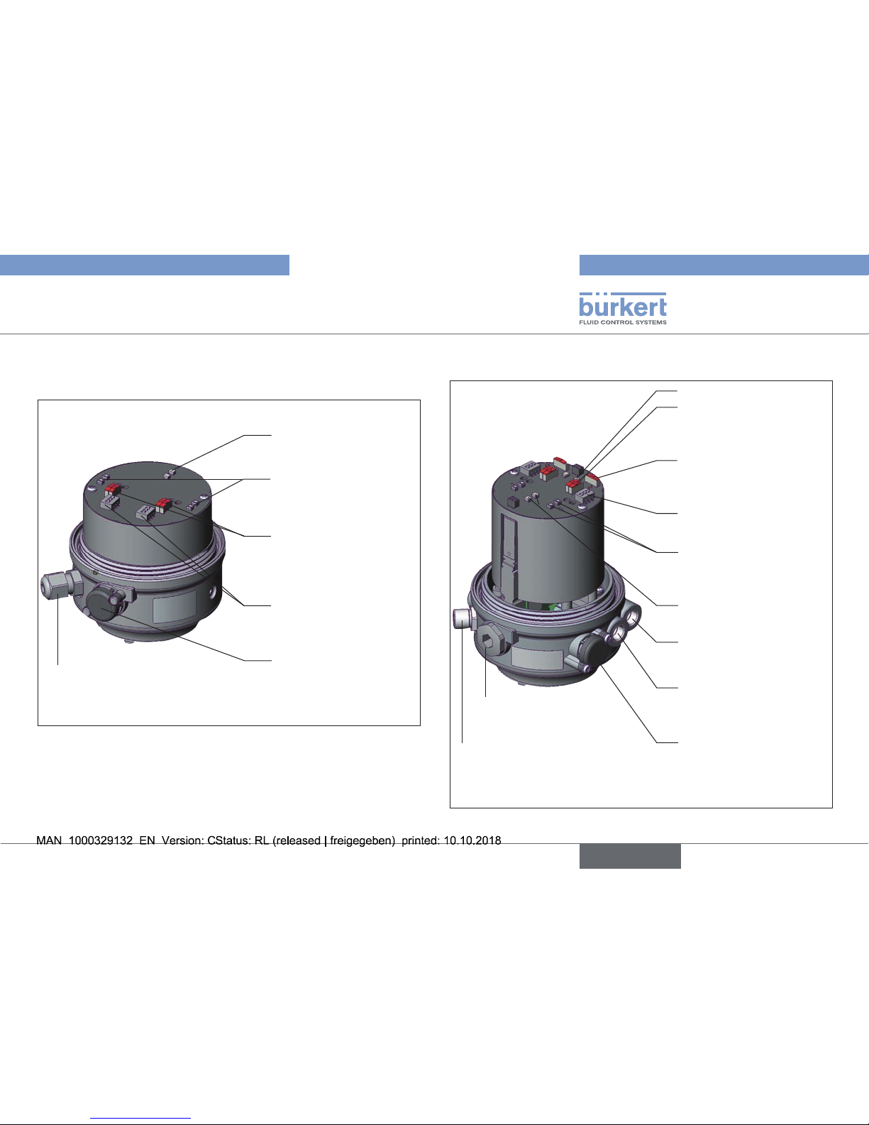
5.3 Structure of feedback head Type
8685
Electrical connection
Cable gland M12 x 1.5 or circular
plug-in connector M12 x 1
Pressure limiting valve
(for protection against
too high internal pressure
in case of error)
AS interface
status LEDs
Drive status OPEN/
CLOSED LEDs
(end position)
DIP switches
Select RV50/70/110
Slide switch
Color selection of
end position
View without
transparent cap:
Fig. 1: Structure of feedback head Type 8685
5.4 Structure of control head Type 8686
Dummy plug
M16 x 1.5
Electrical connection
Cable gland M12 x 1.5
or circular plug-in connector M12 x 1
Pressure limiting valve
(for protection against too
high internal pressure in
case of error)
Exhaust air port
(label: 3)
Pilot air port
(label: 1)
AS-Interface status
LEDs
Actuator status OPEN/
CLOSED LEDs (end
position)
DIP switches
Select RV50/70/110
Slide switch
Color selection of end
position
Slide switch
Pilot valve
(Service switch)
Control valve status LED
View without transparent
cap and body casing:
Fig. 2: Structure of control head Type 8686
English
Type 8685 / 8686
Page 10
10
Technical data
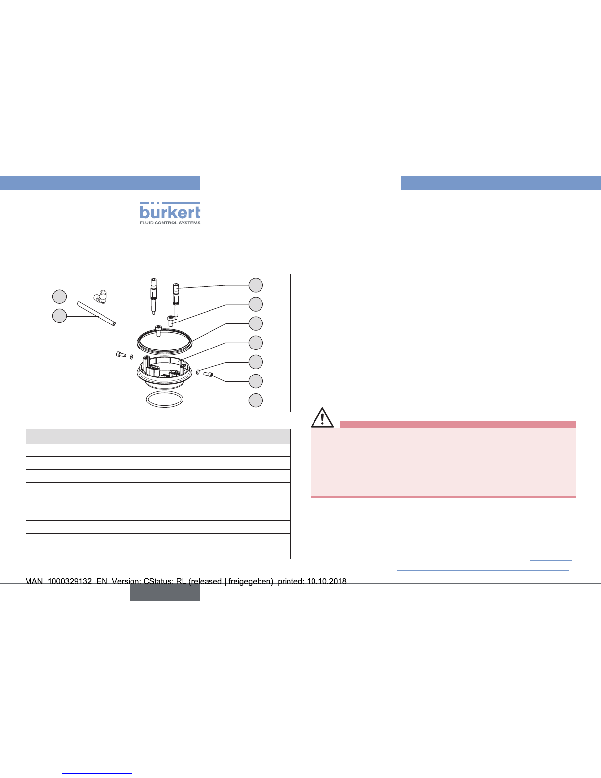
5.5 Structure of adapter set for
actuator Type 2036
2
5
4
1
7
6
3
9
8
Fig. 3: Adapter set for Type 2036
Item Quantity Designation
1 1 Robolux adaptation body
2 6 2 units each Switch spindle RV50, RV70, RV110 cpl.
3 1 O-ring 52 x 3 EPDM 75
4 1 Form seal
5 2 Cylinder head screw M6 x 12 A2 DIN 912
6 2 Cylinder head screw M4 with shaft
7 2 O-ring 3.5 x 1.5 EPDM 70
8 2 Hose 280 mm
9 4 Angular connection G1/8 SL6 Legris
Tab. 1: Parts list for adapter set
6 TECHNICAL DATA
6.1 Conformity
The feedback head Type 8685 and the control head Type 8686 comply
with EU directives in accordance with the EU Declaration of Conformity.
6.2 Standards
The applied standards, which verify conformity with the EU Directives, can be found on the EU Type Examination Certificate and / or
the EU Declaration of Conformity.
6.3 Operating conditions
WARNING!
Solar radiation and temperature fluctuations may cause malfunctions or leaks.
▶ If the device is used outdoors, do not expose it unprotected to
the weather conditions.
▶ Ensure that the permitted ambient temperature does not exceed
the maximum value or drop below the minimum value.
Ambient temperature 0 – +55 °C
Degree of protection IP65 / IP67 according to EN 60529
(only if cables, plugs and sockets have been
connected correctly and in compliance with
the exhaust air concept in chapter “8.3 Pneumatic installation of control head Type 8686”.
English
Type 8685 / 8686
Page 11
11
Technical data
6.4 Mechanical data
Dimensions See data sheet
Body material PPS, PC, VA
Sealing material outside EPDM
inside NBR
Stroke range of valve spindle RV50 actuator size 6 mm
RV70 actuator size 9.5 mm
RV110 actuator size 13.5 mm
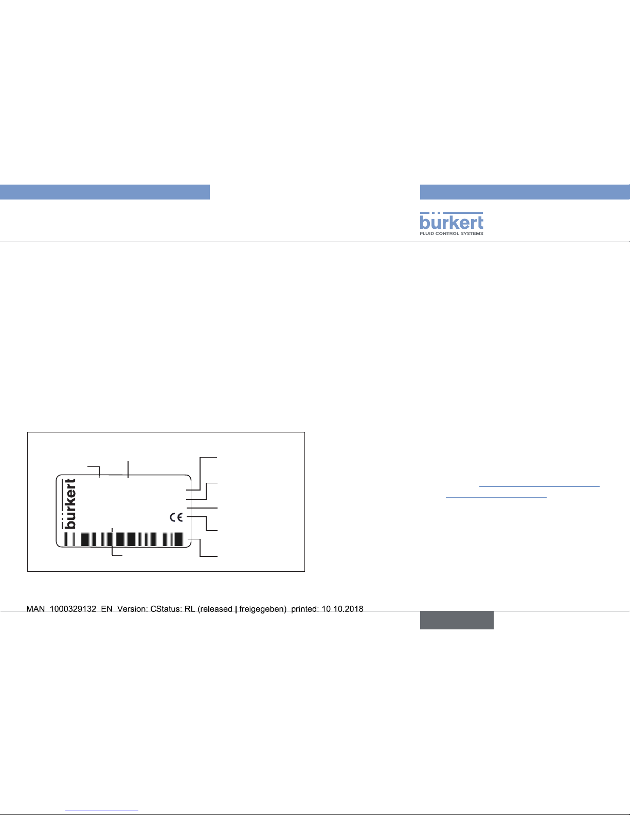
6.5 Type label
Example:
8686 AS-i S-7.A.E
2x single pilot 3.0
Pmax 7bar
Tamb 0 ... +55°C
Ser. No. 001000
00XXXXXX
D-74653 Ingelfingen
W14UN
Identification number
Supply voltage, control or
AS-Interface profile
Max operating
pressure
Type
Control function,
pilot valve
Barcode
Serial number,
CE marking
Ambient
temperature
Fig. 4: Example of type label
6.6 Pneumatic data
Control medium neutral gases, air
Quality classes in accordance with
ISO 8573-1
Dust content Class 7 Max. particle size 40 µm,
max. particle density 10 mg/m³
Water content of Class 3 max. pressure dew point - 20 °C or
min. 10 °C below the lowest
operating temperature
Oil content Class X max. 25 mg/m³
Temperature range
Control medium -10 – + 50 °C
Pressure range
Control medium 6 – 7 bar
(for further details see operating
instructions Type 2036 and
chapter “8.3 Pneumatic installation of
control head Type 8686”)
Air output of pilot valve 250 lN / min (for aeration and deaeration)
(QNn value according to definition for
pressure drop from 7 to 6 bar absolute)
Connections Plug-in hose connector Ø 6 mm / 1/4"
Socket connection G1/8
English
Type 8685 / 8686
Page 12
12
Technical data
6.7 Electrical data for feedback head
Type 8685
6.7.1 Electrical data without bus control
24 V DC
Connections Cable gland M12 x 1.5, wrench size 15
(clamping area 3 – 6.5 mm)
with screw terminals
(nominal cross section 1.0 mm²,
min. cable cross-section 0.25 mm²)
Supply voltage 24 V DC ± 10%,
max. residual ripple 10%
Output max. 100 mA per output /
short circuit-proof
Display max. 20 mA
(2 end positions = 2 LEDs)
6.7.2 Electrical data with AS-Interface bus
control
Connections Remote 975 mm AS-Interface cable
with circular plug-in connector
(M12 x 1, 4-pole)
Supply voltage 29.5 V – 31.6 V DC
(according to specification)
Max. power consumption 35 mA
English
Type 8685 / 8686
Page 13
13
Technical data
6.8 Electrical data
control head Type 8686
6.8.1 Electrical data without bus control
24 V DC
Connections Cable gland M12 x 1.5, wrench size 15
(clamping area 3 – 6.5 mm) with screw terminals
(nominal cross section 1.0 mm²,
min. cable cross-section 0.25 mm²)
Circular plug-in connector (M12 x 1, 8-pole)
Pilot valve
Supply voltage 24 V DC ± 10% ,
max. residual ripple 10%
Power input 2 x 0.8 W
Output max. 100 mA per output / short
circuit-proof
Display max. 20 mA
(2 end positions = 2 LEDs)
Service:
Power consumption 90 mA
(2 end positions + 2 valves /
service switch on)
6.8.2 Electrical data with AS-Interface bus
control
Connections Remote 975 mm AS-Interface cable
with circular plug-in connector
(M12 x 1, 4-pole)
Supply voltage 29.5 V – 31.6 V DC
(according to specification)
Outputs
Max. switching capacity: 2 x 0.8 W via AS-Interface
Watchdog function integrated
Max. power consumption 120 mA
(2 valves when activated +
2 end positions)
Service:
Power consumption 105 mA
(2 end positions
+ 2 valves /
service switch on)
English
Type 8685 / 8686
Page 14
14
Assembly
7 ASSEMBLY
7.1 Safety instructions
DANGER!
Risk of injury from high pressure in the equipment/device.
▶ Before working on equipment or device, switch off the pressure
and deaerate/drain lines.
Risk of electric shock.
▶ Before working on equipment or device, switch off the power
supply and secure to prevent reactivation.
▶ Observe applicable accident prevention and safety regulations
for electrical equipment.
WARNING!
Risk of injury from improper assembly.
▶ Installation may only be carried out by authorized technicians
with the appropriate tools.
Risk of injury from unintentional activation of the system and
uncontrolled restart.
▶ Secure system from unintentional activation.
▶ Following assembly, ensure a controlled restart.
7.2 Assembly of Type 8685 and Type
8686 on the actuator Type 2036
An adapter set is required for assembly on the actuator Type 2036.
The adapter set (see “Fig. 3”, page 10) includes an adaptation body,
a form seal, three O-rings, four cylinder screws and three switch spindle
pairs. There are different adapter sets for feedback head and control
head. Because of the different working height for actuator sizes RV50,
RV70 and RV110, an adapter set contains different spindle lengths.
Switch spindle Type 8685
Switch spindle Type 8686
RV110 RV70
RV50
RV110 RV70
RV50
Actuator size
identification
Cap
Fig. 5: Switch spindle identification
English
Type 8685 / 8686
Page 15

15
Assembly
Designation Order no.
Adapter set for Type 8685 684267
Adapter set for Type 8686 684268
Tab. 2: Adapter sets
Procedure:
Step 1: Assembly of adaptation body on the actuator
→ Unscrew the transparent cap from the actuator.
→ Remove cover foil, if present. This makes the coding holes and M6
threads accessible.
→ Place the 52 x 3 O-ring in the profile on the bottom of the adap-
tation body.
→ Place the adaptation body on the actuator, paying close attention
to the coding pin.
→ Screw the adaptation body tightly onto the actuator with two
cylinder screws M6 x 12.
O-ring 52 x 3
Adaptation body
Coding pin
Cylinder screws M6 x 12
Actuator
Fig. 6: Assembly of adaptation body
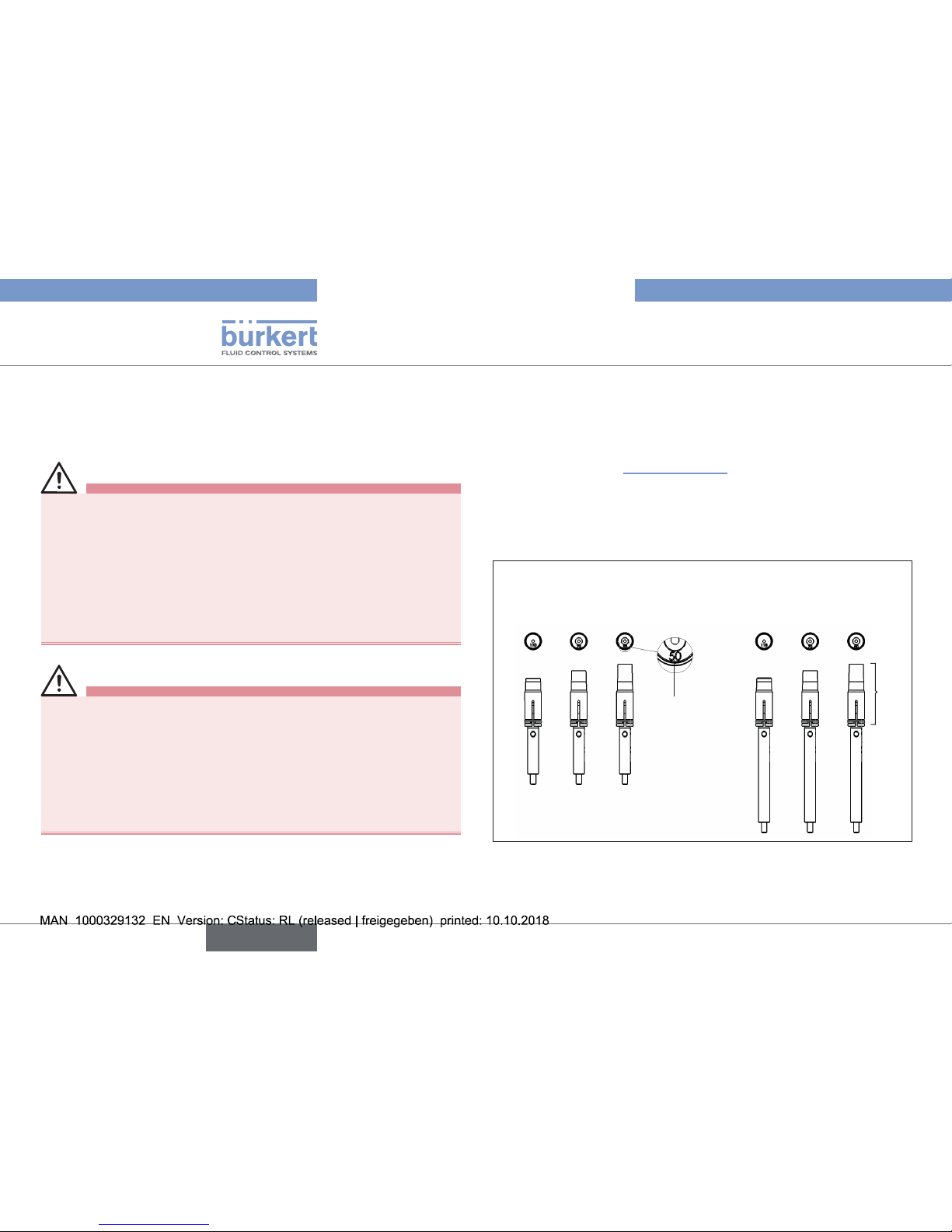
NOTE!
Using a switch spindle that does not fit will result in irreparable destruction of the feedback head and/or control head
and the actuator.
▶ Use only switch spindles that match the actuator size. The cor-
responding actuator size identification (RV50, RV70, RV110)
for switch spindles are embossed on the front of the PVC cap
(see “Fig. 5”).
→ Select the switch spindle that matches the actuator size (see
“Fig. 5: Switch spindle identification”).
→ Wet the thread of two switch spindles that match the actuator
size with Loctite screw locking M290.
NOTE!
Using the wrong spindle lead-through will result in
malfunction.
▶ Use only the spindle lead-through that matches the actuator
size (see “Fig. 7”).
Spindle lead-through
for actuator size
RV50
Spindle lead-through
for actuator sizes
RV70 and RV110
Fig. 7: Spindle lead-through
English
Type 8685 / 8686
Page 16

16
Assembly
NOTE!
No detection or faulty detection of end positions.
▶ Do not change the position of the cap on the switch spindle.
▶ Use the hole ∅ 2.3 for fastening the switch spindle.
→ Push the switch spindles through the matching spindle lead-
throughs. The outside lead-throughs are designed for actuator
size RV70/110, while the inside lead-throughs for actuator size
RV50 (see “Fig. 7”).
→ Attention: Do not bring the screw locking into contact with the
spindle seal.
Hole ∅ 2.3 for
screwing in the
switch spindle
Form seal
Cap
Fig. 8: Assembly of switch spindles and form seal
→ Using a suitable tool, screw the two switch spindles onto the
actuator spindles. There is a hole ∅ 2.3 on the spindle side for
this purpose (torque 1.0 Nm ± 0.1 Nm).
→ Place the form seal on the adaptation body (smaller diameter
points upwards).
Step 2: Assembly of the feedback head / control head on the
adaptation body
If the electrical connection is made with a cable gland, we
recommend connecting the wires at this point, since otherwise
the feedback head / control head will have to be removed again
for the electrical connection.
For electrical installation see: “9.2 Device version 24 V DC”
“Device connection for cable gland Type 8685”
“Device connection for cable gland Type 8686”
NOTE!
Faulty detection of end positions.
▶ For actuators with control function B (CFB, NO), the lower end
position must be approached before the feedback head / control
head is placed on the adaptation body. To do this, pressurize the
appropriate pilot air port of the actuator (“Fig. 9”).
▶ Make certain the feedback head / control head is correctly posi-
tioned relative to the actuator: The dummy plug or pressure-relief
valve must be located on the side of the pneumatic connections
of the actuator (see “Fig. 9”).
→ Place the feedback head / control head on the actuator. As you
do, note:
- The dummy plug or pressure-relief valve must be located on the
side of the pneumatic connections of the actuator.
-
The caps must be in the starting position. If not, move the caps
to the starting position (see “Fig. 5”)
- The switch spindles must lodge inside the recesses on the bottom
of the feedback head / control head. Do not move the caps onto
the switch spindles.
English
Type 8685 / 8686
Page 17

17
Assembly
Form seal
Dummy plug
Pressure-relief
valve
Connection
CFB
Connection
CFA
Type 2036
Type 8686
Type 8685
Pneumatic actuator
connections
Switch spindle
Recess
Fig. 9: Assembly of feedback head / control head
→ Push the feedback head / control head onto the adaptation body
until no gap is visible on the form seal. Now align the mounting hole
of the feedback head / control head on each side with the square
nut of the adaptation body.
Fastening screw M4
Mounting hole of the
feedback head / control
head concentric with
square nut of the adap-
tation body
O-ring 3.5 x 1.5
Fig. 10: Fastening of feedback head / control head
NOTE!
If the torque is too high when screwing in the fastening screw
or if the O-ring is missing, degree of protection IP65 / IP67 is
not ensured.
▶ The fastening screw may only be tightened to a maximum torque
of 0.5 Nm ± 0.1 Nm.
▶ Check the position of the O-ring.
→ Use the two fastening screws M4 and matching O-rings to
fasten the feedback head / control head onto the adaptation
body (torque: 0.5 Nm ± 0.1 Nm).
The mechanical connection is already completed for the feedback
head after these two assembly steps. “Step 3: Assembly of pneumatic connection - install the actuator” must still be performed for
the control head.
English
Type 8685 / 8686
Page 18

18
Assembly
Control head Type 8686 only:
Step 3: Assembly of pneumatic connection - install the actuator
→ Screw the plug-in hose connectors onto the control head and the
actuator.
→ Cut the enclosed hoses (2 x 280 mm) to length as appropriate
for the device layout.
→ Using the hoses supplied in the accessory kit, make the pneumatic
connection between the control head and actuator according to
the control function (CF) with the following “Tab. 3: Overview of
pneumatic connections for actuator variants”.
Plug-in hose
connectors
Hoses
Fig. 11: Assembly of pneumatic connections
NOTE!
Damage or malfunction due to ingress of dirt and moisture.
▶ To comply with degree of protection IP65 / IP67, install an
exhaust air line on the unneeded pilot air port (for CFA, NC and
CFB, NO) in the dry area.
Pilot air port
2 (P2)
Pilot air port
4 (P4)
Pilot air port
3 (P3)
Pilot air port
1 (P1)
Actuator 1
(left)
Actuator 2
(right)
Pilot air outputs for
control head
Fig. 12: Pneumatic connection
English
Type 8685 / 8686
Page 19

19
Pneumatic installation
Type 2036 Actuator 1 Actuator 2
CF Connection CF Connection
D11, D55
CFA/CFA
CFA
2
1
P1
P2: Deaeration
CFA
2
2
P3
P4: Deaeration
D12
CFA/CFB
CFA
2
1
P1
P2: Deaeration
CFB
2
2
P4
P3: Deaeration
D21
CFB/CFA
CFB
2
1
P2
P1: Deaeration
CFA
2
2
P3
P4: Deaeration
D22
CFB/CFB
CFB
2
1
P2
P1: Deaeration
CFB
2
2
P4
P3: Deaeration
Tab. 3: Overview of pneumatic connections for actuator variants
CFA, NC: Valve closed in rest position (by spring force)
CFB, NO: Valve open in rest position (by spring force)
For the assignment of control connections see the installation and dimensional drawing included with delivery of the
valve or in the Type 2036 operating instructions.
8 PNEUMATIC INSTALLATION
The dimensions of the feedback head / control head and the different
complete device models, consisting of control, feedback head / control
head, actuator and valve, can be found in the relevant data sheets.
8.1 Safety instructions
DANGER!
Risk of injury from high pressure in the equipment/device.
▶ Before working on equipment or device, switch off the pressure
and deaerate/drain lines.
Risk of electric shock.
▶ Before working on equipment or device, switch off the power
supply and secure to prevent reactivation.
▶ Observe applicable accident prevention and safety regulations
for electrical equipment.
WARNING!
Risk of injury from improper installation.
▶ Installation may only be carried out by authorized technicians
with the appropriate tools.
Risk of injury from unintentional activation of the system and
uncontrolled restart.
▶ Secure system from unintentional activation.
▶ Following installation, ensure a controlled restart.
English
Type 8685 / 8686
Page 20

20
Pneumatic installation
8.2 Pneumatic installation of
feedback head Type 8685
The feedback head does not require a pilot air supply.
A description of the pneumatic installation of the actuator is
included in the valve operating instructions.
8.3 Pneumatic installation of control
head Type 8686
DANGER!
Risk of injury from high pressure in the equipment/device.
▶ Before working on equipment or device, switch off the pressure
and deaerate/drain lines.
Procedure:
→ Connect the control medium to the pilot air port (1)
(6 – 7 bar; instrument air, free of oil, water and dust).
→ Mount the exhaust air line or a silencer on the exhaust air port (3)
(see “Fig. 13: Pneumatic connection Type 8686”).
Important information for the problem-free functioning of
the device:
▶ The installation must not cause back pressure to build up.
▶ To make the connection, select a hose with sufficient cross
section.
▶ The exhaust air line must be designed in such a way that
no water or other liquid can get into the device through the
exhaust air connection (3).
Pilot air port
Label: 1
Exhaust air port
Label: 3
Fig. 13: Pneumatic connection Type 8686
Caution (exhaust air concept): In compliance with degree
of protection IP65 / IP67, an exhaust air line must be
installed in the dry area.
Always maintain an applied control pressure of at least
0.5 – 1 bar above the pressure which is required to move the
actuator to its end position.
English
Type 8685 / 8686
Page 21

21
Electrical installation
9 ELECTRICAL INSTALLATION
9.1 Safety instructions
DANGER!
Risk of electric shock.
▶ Before working on equipment or device, switch off the power
supply and secure to prevent reactivation.
▶ Observe applicable accident prevention and safety regulations
for electrical equipment.
WARNING!
Risk of injury from improper installation.
▶ Installation may only be carried out by authorized technicians
with the appropriate tools.
Risk of injury from unintentional activation of the system and
uncontrolled restart.
▶ Secure system from unintentional activation.
▶ Following installation, ensure a controlled restart.
9.2 Device version 24 V DC
9.2.1 Electrical installation for feedback
head Type 8685
Device connection for cable gland Type 8685
→ Use a cable cross-section of 0.25 mm² for the electrical
connection.
Fastening
screws
M4 (2x)
Screw terminals
Fig. 14: Position of screw terminals Type 8685
→ Loosen the fastening screws M4 and pull the feedback head up
(only if the feedback head is already installed).
→ Install the cable gland, if necessary (approx. 1,5 Nm).
→ Guide the cables through the cable gland.
English
Type 8685 / 8686
Page 22

22
Electrical installation
GND24V
Top1
Bot1
Top2
Bot2
Fig. 15: Designation on PCB Type 8685
Designation
on PCB
Assignment
1)
24 V
Supply voltage + 24 V DC ±10%
GND
Supply voltage - GND
Top 1
Top end position Top actuator 1
24 V / 0 V (max. 0.1 A)
GND
Bot 1
Bottom end position Bot actuator 1
24 V / 0 V (max. 0.1 A)
GND
Top 2
Top end position Top actuator 2
24 V / 0 V (max. 0.1 A)
GND
Bot 2
Bottom end position Bot actuator 2
24 V / 0 V (max. 0.1 A)
GND
Tab. 4: Connection for cable gland Type 8685
1) Actuator assignment see “Fig. 16”.
Pilot air port
2 (P2)
Pilot air port
4 (P4)
Pilot air port
3 (P3)
Pilot air port
1 (P1)
Actuator 1
(left)
Actuator 2
(right)
Fig. 16: Pneumatic connection
→ Connect the wires (see pin assignment in “Tab. 4”).
NOTE!
Damage or malfunction due to ingress of dirt and moisture.
▶ To ensure degree of protection IP65 / IP67, tighten the union
nut of the cable gland according to the cable size you are using
(approx. 1.5 Nm).
→ Tighten the union nut of the cable gland on the body (approx. 1.5
Nm).
English
Type 8685 / 8686
Page 23

23
Electrical installation
NOTE!
Faulty detection of end positions.
▶ For actuators with control function B (CFB, NO), the lower end
position must be approached before the feedback head is placed
on the adaptation body. To do this, pressurize the appropriate pilot
air port of the actuator (“Fig. 9”).
▶ Make certain the feedback head is correctly positioned relative
to the actuator: The dummy plug or pressure-relief valve must be
located on the side of the pneumatic connections of the actuator
(see “Fig. 9”).
→ Place the feedback head on the actuator. As you do, note:
- The dummy plug or pressure-relief valve must be located on the
side of the pneumatic connections of the actuator.
-
The caps must be in the starting position. If not, move the caps
to the starting position (see “Fig. 5”)
- The switch spindles must lodge inside the recesses on the
bottom of the feedback head. Do not move the caps onto the
switch spindles.
→ Push the feedback head onto the adaptation body until no gap is
visible on the form seal. Now align the mounting hole of the feedback
head on each side with the square nut of the adaptation body.
NOTE!
If the torque is too high when screwing in the fastening screw
or if the O-ring is missing, degree of protection IP65 / IP67 is
not ensured.
▶ The fastening screw may only be tightened to a maximum torque
of 0.5 Nm ± 0.1 Nm.
▶ Check the position of the O-ring.
→ Use the two fastening screws M4 and matching O-rings to
fasten the feedback head onto the adaptation body (torque: 0.5
Nm ± 0.1 Nm).
When the supply voltage is applied, the feedback head is operating.
→ Before the device can be used, the basic settings (see section
“10.3.1 Basic settings”) must still be made on the feedback
head.
English
Type 8685 / 8686
Page 24

24
Electrical installation
9.2.2 Electrical installation of control head
Type 8686
Device connection for circular plug-in connector Type 8686
→ Connect the circular plug-in connector of the control head as
described in “Tab. 5”.
6
1
7
5
4
3
2
8
Fig. 17: Assignment of circular plug (M12 x 1, 8-pole)
Use only straight connecting socket.
Pilot air port
2 (P2)
Pilot air port
4 (P4)
Pilot air port
3 (P3)
Pilot air port
1 (P1)
Actuator 1
(left)
Actuator 2
(right)
Fig. 18: Pneumatic connection
When the supply voltage is applied, the control head is operating.
→ Before the device can be used, the basic settings (see section
“10.3.1 Basic settings”) must still be made on the control head.
Pin
Wire
color
2)
Assignment
3)
External circuit
1
white
Bottom end position Bot actuator 2
24 V / 0 V (max. 0.1 A)
GND (7)
1
2
brown
Top end position Top actuator 2
24 V / 0 V (max. 0.1 A)
GND (7)
2
3
green
Bottom end position Bot actuator 1
24 V / 0 V (max. 0.1 A)
GND (7)
3
4
yellow
Top end position Top actuator 1
24 V / 0 V (max. 0.1 A)
GND (7)
4
5
gray
Valve control Y2
Actuator 2 activated
high active, to activate
connect with 24 V
5
6
pink
Valve control Y1
Actuator 1 activated
high active, to activate
connect with 24 V
6
7
blue Supply voltage – GND
7
8
8
red Supply voltage + 24 V DC ±10%
Tab. 5: Connection for circular plug-in connector Type 8686
2) The indicated colors refer to the connecting cable available as an
accessory (919061).
3) Actuator assignment see “Fig. 18”.
English
Type 8685 / 8686
Page 25

25
Electrical installation
Device connection for cable gland Type 8686
→ Use a cable cross-section of 0.25 mm² for the electrical connection.
Fastening
screws
M4 (2x)
Screw terminals
Cable holder
Fig. 19: Position of screw terminals Type 8686
→ Loosen the fastening screws M4 and pull the control head up
(only if the control head is already installed).
→ Install the cable gland, if necessary (approx. 1,5 Nm).
Valve1
GND
24V
Valve2
Top1
Bot1
Top2
Bot2
Fig. 20: Designation on PCB Type 8686
→ Guide the cables through the cable gland.
→ Connect the wires (see pin assignment in “Tab. 6”).
Designation
on PCB
Assignment
4)
External circuit
Bot2
Bottom end position Bot actuator 2
24 V / 0 V (max. 0.1 A)
GND
Top2
Top end position Top actuator 2
24 V / 0 V (max. 0.1 A)
GND
Bot1
Bottom end position Bot actuator 1
24 V / 0 V (max. 0.1 A)
GND
Top1
Top end position Top actuator 1
24 V / 0 V (max. 0.1 A)
GND
Valve2
Valve control Y2
Actuator 2 activated
high active, to activate
connect with 24 V
Valve1
Valve control Y1
Actuator 1 activated
high active, to activate
connect with 24 V
GND
Supply voltage - GND
24V
Supply voltage + 24 V DC ±10%
Tab. 6: Connection for cable gland Type 8686
4) Actuator assignment see “Fig. 18”.
English
Type 8685 / 8686
Page 26

26
Electrical installation
NOTE!
Malfunction due to damaged wires.
▶ To keep the spindle guides free, guide all wires through the
cable holders.
Damage or malfunction due to ingress of dirt and moisture.
▶ To ensure degree of protection IP65 / IP67, tighten the union
nut of the cable gland according to the cable size you are using
(approx. 1.5 Nm).
→ Guide all wires through the cable holders.
→ Tighten the union nut of the cable gland on the body (approx. 1.5
Nm).
NOTE!
Faulty detection of end positions.
▶ For actuators with control function B (CFB, NO), the lower end
position must be approached before the control head is placed
on the adaptation body. To do this, pressurize the appropriate pilot
air port of the actuator (“Fig. 9”).
▶ Make certain the control head is correctly positioned relative to
the actuator: The dummy plug or pressure-relief valve must be
located on the side of the pneumatic connections of the actuator
(see “Fig. 9”).
→ Place the control head on the actuator. As you do, note:
- The dummy plug or pressure-relief valve must be located on the
side of the pneumatic connections of the actuator.
-
The caps must be in the starting position. If not, move the caps
to the starting position (see “Fig. 5”)
- The switch spindles must lodge inside the recesses on the bottom
of the control head. Do not move the caps onto the switch spindles.
→ Push the control head onto the adaptation body until no gap is
visible on the form seal. Now align the mounting hole of the control
head on each side with the square nut of the adaptation body.
NOTE!
If the torque is too high when screwing in the fastening screw
or if the O-ring is missing, degree of protection IP65 / IP67 is
not ensured.
▶ The fastening screw may only be tightened to a maximum torque
of 0.5 Nm ± 0.1 Nm.
▶ Check the position of the O-ring.
→ Use the two fastening screws M4 and matching O-rings to
fasten the control head onto the adaptation body (torque:
0.5 Nm ± 0.1 Nm).
When the supply voltage is applied, the control head is operating.
→ Before the device can be used, the basic settings (see section
“10.3.1 Basic settings”) must still be made on the control head.
English
Type 8685 / 8686
Page 27

27
Electrical installation
9.3 Device version AS-Interface
9.3.1 Electrical installation feedback head
and control head
The feedback head and control head are electrically connected by a
multi-pole cable (M12 circular plug-in connector) and flat cable terminal. The circular plug can simply be connected with the flat cable
terminal (see “Fig. 21”).
Screws
M12 plug-in connector branch circuit
Fig. 21: Feedback head / control head with multi-pole cable and
flat cable terminal
Wiring diagram of circular plug M12
The view shows the image from the front looking at the pins, the solder
connections are behind them.
Pin 4:
NC
Pin 1:
Bus +
Pin 3:
Bus –
Pin 2:
NC
Fig. 22: Bus connection
Pin Designation Assignment
1
Bus + AS-Interface bus line +
2
NC not used
3
Bus – AS-Interface bus line –
4
NC not used
Tab. 7: Pin assignment of circular plug-in connector for
AS-Interface
English
Type 8685 / 8686
Page 28

28
Electrical installation
Handling the flat cable terminal
The multi-pole cable features a flat cable terminal - with M12 plug-in
connector branch circuit - for AS-Interface cable harness. The flat cable
terminal contacts the AS-Interface flat cable by means of penetration
technology which allows installation by “clipping in” the AS-Interface
flat cable without cutting and without removing insulation.
Procedure:
→ Open the flat cable terminal
(loosen screws and remove cover).
→ Insert flat cable to fit closely.
→ Close flat cable terminal again.
→ Tighten the screws
Loosen the thread-forming screws slightly (approx. 3/4 turn to the
left) and position them on the existing threaded hole and screw in.
9.3.2 AS-Interface connection
AS-Interface (Actuator Sensor Interface) is a field bus system
which is used primarily for networking binary sensors and actuators
(slaves) with a higher-level control (master).
Bus line
Unshielded two-wire line (AS-Interface line as AS-Interface flat
cable) along which both information (data) and energy (power
supply voltage for the actuators and sensors) are transmitted.
Network topology
Freely selectable within wide limits, i.e. star, tree and line networks
are possible. Further details are described in the AS-Interface Specification (A/B slave model conforms to the version 3.0 specification
9.3.3 Technical Data for AS-Interface PCBs
Supply: via AS-Interface (29.5 V – 31.6 V)
Control head outputs: Valve Y1 and valve Y2,
each with max. 0.8 W,
Power reduction after approx. 100 ms
with integrated watchdog function
Certification: Feedback head: Certificate No. 94701
based on version 3.0
Control head: Certificate No. 94801
based on version 3.0
9.3.4 Programming data
Programming data for feedback head Type 8685
I/O configuration 0 hex
ID code
A hex (see below for bit
configuration)
Extended ID code 1 7 hex
Extended ID code 2 E hex
Profile S-0.A.E
Tab. 8: Programming data for feedback head Type 8685
English
Type 8685 / 8686
Page 29

29
Electrical installation
Bit configuration
Data bit
Inputs
Function Assignment
5)
D0
Top end position Top actuator 1
0 Top not reached
1 Top reached
D1
Bottom end position Bot actuator 1
0 Bot not reached
1 Bot reached
D2
Top end position Top actuator 2
0 Top not reached
1 Top reached
D3
Bottom end position Bot actuator 2
0 Bot not reached
1 Bot reached
Data bit
Outputs
Function Assignment
5)
D0 - not used
D1 - not used
D2 - not used
D3 - not used
Tab. 9: Bit configuration of AS-Interface for feedback head Type 8685
Parameter bits have no function.
5) Actuator assignment see “Fig. 23”.
Programming data for control head Type 8686:
I/O configuration 7 hex
ID code A hex (see below for bit configuration)
Extended ID code 1 7 hex
Extended ID code 2 E hex
Profile S-7.A.E
Tab. 10: Programming data for control head Type 8686
Pilot air port
2 (P2)
Pilot air port
4 (P4)
Pilot air port
3 (P3)
Pilot air port
1 (P1)
Actuator 1
(left)
Actuator 2
(right)
Fig. 23: Pneumatic connection
English
Type 8685 / 8686
Page 30

30
Electrical installation
Bit configuration
Data bit
Inputs
Function Assignment
6)
D0
Top end position Top actuator 1
0 Top not reached
1 Top reached
D1
Bottom end position Bot actuator 1
0 Bot not reached
1 Bot reached
D2
Top end position Top actuator 2
0 Top not reached
1 Top reached
D3
Bottom end position Bot actuator 2
0 Bot not reached
1 Bot reached
Data bit
Outputs
Function Assignment
6)
D0 Pilot valve Y1
0 Pilot valve OFF
1 Pilot valve ON
D1 Pilot valve Y2
0 Pilot valve OFF
1 Pilot valve ON
D2 - not used
D3 - not used
Tab. 11: Bit configuration of AS-Interface for control head Type 8686
Parameter bits have no function.
6) Actuator assignment see “Fig. 24”.
9.3.5 LED status display for AS-Interface
Status LED 1
(green)
Status LED 2
(red)
off off POWER OFF
off on
No data traffic (expired Watch
Dog at slave address does not
equal 0)
on off OK
flashing on Slave address equals 0
Tab. 12: LED status display for AS-Interface
Pilot air port
2 (P2)
Pilot air port
4 (P4)
Pilot air port
3 (P3)
Pilot air port
1 (P1)
Actuator 1
(left)
Actuator 2
(right)
Fig. 24: Pneumatic connection
English
Type 8685 / 8686
Page 31

31
Control and display
10 CONTROL AND DISPLAY
10.1 Control and display elements for
feedback head Type 8685
10.1.1 Device version 24 V DC
The items listed below are designed separately for actuator 1 and 2.
Display elements:
• Status of actuator (end position)
The display elements are designed in the form of an LED.
Control elements:
• DIP switch for selecting actuator size RV50, RV70, RV110
• Slide switch for color selection of end position
If the transparent cap is unscrewed, follow the instructions
in “Step 4: Closing the transparent cap / body casing”,
page 36.
DIP switch -
actuator 1
DIP switch actuator 2
Slide switch
Color selection of end position
Actuator 2
Slide switch
Color selection of end position
Actuator 1
LEDs
Status of actuator 2
(end position)
LEDs
Status of actuator 1
(end position)
Fig. 25: Control and display elements for 24 V DC feedback head
English
Type 8685 / 8686
Page 32

32
Control and display
10.1.2 Device version AS-Interface
Other than the AS-Interface bus status, the items listed below are
designed separately for actuator 1 and 2.
Display elements:
• AS-Interface bus status
• Status of actuator (end position)
The display elements are designed in the form of an LED.
Control elements:
• DIP switch for selecting actuator size RV50, RV70, RV110
• Slide switch for color selection of end position
If the transparent cap is unscrewed, follow the instructions
in “Step 4: Closing the transparent cap / body casing”,
page 36.
LEDs
AS Interface bus status
DIP switch -
actuator 1
DIP switch actuator 2
Slide switch for
color selection of end position
Actuator 2
Slide switch for
color selection of end position
Actuator 1
LEDs
Status of actuator 2
(end position)
LEDs
Status of actuator 1
(end position)
Fig. 26: Control and display elements for AS-Interface feedback
head
English
Type 8685 / 8686
Page 33

33
Control and display
10.2 Control and display elements for
control head Type 8686
The items listed below are designed separately for actuator 1 and 2.
Device versions 24 V DC and AS-Interface have the same display
and control PCB.
The AS-Interface bus status LEDs are accordingly inactive for the
24 V DC device version.
Display elements:
• AS-Interface bus status
• Status of actuator (end position)
• Status of pilot valve
The display elements are designed in the form of an LED.
Control elements:
• DIP switch for selecting actuator size RV50, RV70, RV110
• Slide switch for color selection of end position
• Slide switch for direct activation of pilot valves (service switch)
If the transparent cap / the body casing is unscrewed,
follow the instructions in “Step 4: Closing the transparent
cap / body casing”, page 36.
DIP switch -
actuator 1
DIP switch actuator 2
Slide switch
Color selection of end position
Actuator 2
Slide switch
Color selection of end position
Actuator 1
Slide switch
(service switch)
Pilot valve for actuator 2
Slide switch
(service switch)
Pilot valve for actuator 1
LED status of pilot valve
Actuator 2
LED status of pilot valve
Actuator 1
LEDs
AS Interface bus status
LEDs
Status of actuator 2
(end position)
LEDs
Status of actuator 1
(end position)
Fig. 27: Control and display elements - control head
English
Type 8685 / 8686
Page 34

34
Control and display
10.3 Control
10.3.1 Basic settings
To ensure the function of Types 8685 and 8686, these basic settings must be made before start-up in the isolated state.
DANGER!
Risk of electric shock.
▶ Before working on equipment or device, switch off the power
supply and secure to prevent reactivation.
▶ Observe applicable accident prevention and safety regulations
for electrical equipment.
→ Unscrew the transparent cap.
→ Perform steps 1 to 4.
Step 1: Select the actuator size
The control elements are designed for one actuator side only.
Switch only one DIP switch element per actuator size to
active, depending on the actuator size (see actuator type
label). Only one uniform actuator size needs to be selected
on both actuator sides.
Incorrect settings of the DIP switches result in malfunctions
or no function of the end position feedback.
→ Pushing a DIP switch element to the “ON” position causes the
end position sensors of the selected actuator size to be activated.
RV110
RV70
RV50
ACTUATOR
1 2 3
ON
ON
Type 8685
Type 8686
Fig. 28: Selection of actuator size via DIP switch
Step 2: Change the assignment of the end position LEDs
(actuator status)
You can set the color assignment of the end positions with these
slide switches. You can indicate for each color whether it applies to
the Top (upper end position) or Bot (lower end position).
The slide switches for color selection must be unambiguously selected inside the actuator chamber, i.e. both
switches must be up or both must be down.
Incorrect settings of these switches will result in an
incorrect visual interpretation of end position detection, but
the end position detection will still be correct.
English
Type 8685 / 8686
Page 35

35
Control and display
Bot
gn ye
Bot
Top
Top
Typ 8685
Typ 8686
Fig. 29: Color assignment of end positions via slide switch
Refer to the PCB labeling in the table below
Switch position for one
actuator side
Actuator status LED
Both switches up End position Top yellow /
End position Bot green
Both switches down End position Top green /
End position Bot yellow
Switch up/down - Invalid state -
Switch down/up - Invalid state -
Tab. 13: Color assignment of end positions
The following function is set in the factory:
Color Actuator status
Green LED lit Lower end position
Yellow LED lit Upper end position
Tab. 14: Assignment of status of actuator LEDs (end position)
Step 3: Reference movement for spindle adjustment
To make the fine adjustment of the spindle for actuator size, it is essential
to move both spindles from the lower to the top end position.
Procedure for Type 8685:
Actuator with design control function A (CFA, NC):
→ Under maximum control pressure, move the spindles up by acti-
vating the actuator chambers.
→ After the end position is reached (preselected LED is lit), turn off
the control pressure. The spindle moves to the lower end position.
LED for end position Bot is lit with the selected color.
Actuator with design control function B (CFB, NO):
→ Under maximum control pressure, move the spindles down by
activating the actuator chambers.
→ After the end position is reached (preselected LED is lit), turn
off the control pressure. The spindle moves to the upper end
position. The corresponding LED for the end position is lit with
the selected color.
English
Type 8685 / 8686
Page 36

36
Control and display
Procedure for Type 8686:
→ Under maximum control pressure, switch the service switch to “On”.
The spindle moves to the upper end position.
→ After the end position is reached (preselected actuator status LED
is lit), switch the service switch back to “Off”. The spindle moves
to its initial position. The corresponding actuator status LED for the
end position is lit with the selected color.
ON
Service
OFF
Service
ON
OFF
Service switch
Pilot valve status LED
Fig. 30: Spindle adjustment
Step 4: Closing the transparent cap / body casing
→ Check that the seal is correctly positioned in the transparent cap
/ body casing (see “Fig. 31”).
NOTE!
Damage or malfunction due to ingress of dirt and moisture.
▶ To comply with degree of protection IP65 / IP67, screw in the
transparent cap / body casing all the way.
→ Close the transparent cap / body casing (auxiliary tool for
installing the cover: 6740777)).
Seal
body casing
Body casing
Type 8686
Type 8685
Seal
transparent cap
Transparent cap
Fig. 31: Position of the seal in the transparent cap / body casing
The device is now configured and ready for operation.
7) The auxiliary tool for installing the cover (674077) is available through
your Bürkert sales office.
English
Type 8685 / 8686
Page 37

37
Control and display
10.3.2 Changing the settings
Procedure:
→ Unscrewing the transparent cap makes the slide switches and DIP
switches accessible.
→ Select the actuator size with the DIP switches. Only one uniform
actuator size needs to be selected on both actuator sides (see
valve type label).
→ Use the “Tab. 13: Color assignment of end positions” or the labeling
on the PCB to assign the desired color to the actuator status LEDs
(end position).
→ Check that the seal is correctly positioned in the transparent cap
/ body casing (see “Fig. 31”).
NOTE!
Damage or malfunction due to ingress of dirt and moisture.
▶ To comply with degree of protection IP65 / IP67, screw in the
transparent cap / body casing all the way.
→ Close the transparent cap / body casing (auxiliary tool for
installing the cover: 6740778)).
8) The auxiliary tool for installing the cover (674077) is available through
your Bürkert sales office.
10.3.3 Manual activation of pilot valves
with the control head Type 8686
The pilot valves can be switched with the service switches. With
control function A, the spindle moves up with switch position
“On”. With control function A, the spindle moves down with switch
position “On”.
ON
Service
OFF
Service
ON
OFF
Slide switch
(service switch)
Pilot valve for actuator 1
LED status
Pilot valve for actuator 2
Slide switch
(service switch)
Pilot valve for actuator 2
LED status
Pilot valve for actuator 1
Fig. 32: Service switch and status LEDs for pilot valve (Type 8686)
Procedure:
Voltage is absolutely essential on the device!
→ Unscrewing the transparent cap makes the service switches
accessible.
→ Switch the relevant pilot valve with the service switches.
→ Check that the seal is correctly positioned in the transparent cap
/ body casing (see “Fig. 31”).
English
Type 8685 / 8686
Page 38

38
Control and display
NOTE!
Damage or malfunction due to ingress of dirt and moisture.
▶ To comply with degree of protection IP65 / IP67, screw in the
transparent cap / body casing all the way.
→ Close the transparent cap / body casing (auxiliary tool for
installing the cover: 6740779)).
Procedure for replacing the diaphragm for Type 2036
Voltage is absolutely essential on the device!
→ Unscrewing the transparent cap makes the service switches
accessible.
→ Replace the diaphragm as described in the operating instruc-
tions for Type 2036.
→ After the diaphragm is replaced, perform a reference movement for
spindle adjustment (see “10.3.1 Basic settings”, step 3).
→ Check that the seal is correctly positioned in the transparent cap
/ body casing (see “Fig. 33”).
NOTE!
Damage or malfunction due to ingress of dirt and moisture.
▶ To comply with degree of protection IP65 / IP67, screw in the
transparent cap / body casing all the way.
→ Close the transparent cap (auxiliary tool for installing the cover:
6740779)).
Seal
body casing
Body casing
Type 8686
Fig. 33: Position of the seal in the body casing
9) The auxiliary tool for installing the cover (674077) is available through
your Bürkert sales office.
English
Type 8685 / 8686
Page 39

39
Safety positions
11 SAFETY POSITIONS
Safety positions after failure of the electrical or pneumatic auxiliary
power:
Actuator
type
Designation
Safety positions after failure
of the auxiliary power
electrical pneumatic
up
down
single-acting
Control
function A
down down
up
down
single-acting
Control
function B
up up
Tab. 15: Safety positions
12 MAINTENANCE
12.1 Safety instructions
DANGER!
Risk of injury from high pressure in the equipment/device.
▶ Before working on equipment or device, switch off the pressure
and deaerate/drain lines.
Risk of electric shock.
▶ Before working on equipment or device, switch off the power
supply and secure to prevent reactivation.
▶ Observe applicable accident prevention and safety regulations
for electrical equipment.
WARNING!
Risk of injury from improper maintenance.
▶ Maintenance may only be carried out by authorized technicians
with the appropriate tools.
Risk of injury from unintentional activation of the system and
uncontrolled restart.
▶ Secure system from unintentional activation.
▶ Following maintenance, ensure a controlled restart.
English
Type 8685 / 8686
Page 40

40
Maintenance
12.2 Service at the air intake filter
DANGER!
Risk of injury from high pressure in the equipment/device.
▶ Before working on equipment or device, switch off the pressure
and deaerate/drain lines.
To protect the internal pilot valves and the actuator, the control air is
filtered.
The direction of flow of the air intake filter in installed state is from
the inside to the outside through the filter material.
Air intake filter
Quick connector
O-ring
Fig. 34: Service at the air intake filter
Procedure:
→ Unlock the quick connector by pressing the holding element and
pulling out the air intake filter (if necessary, use a suitable tool in
between the recesses in the head of the filter).
→ Clean the filter or, if necessary, replace the filter.
→ Check inner O-ring and, if required, clean.
→ Insert the air intake filter all the way into the quick connector.
DANGER!
Risk of injury due to improper installation.
▶ Ensure that the air intake filter is installed correctly.
→ Check that the air intake filter is secure.
English
Type 8685 / 8686
Page 41

41
Malfunctions
13 MALFUNCTIONS
Malfunction Cause and remedial action
End position is
not detected
No or inadequate supply voltage
→ Check the electrical connection and supply
voltage
Wrong size of switch spindles from the adapter
set
→ Replace switch spindles
Wrong spindle lead-through selected for
spindle installation
→ Push the switch spindle through the
matching spindle lead-through
Wrong actuator size selected with the DIP
switches
→ Select the matching actuator size
Cap of the switch spindle moved by force
during assembly
→ Remove the feedback head / control head
→ Pull the cap towards the end of the switch
spindle until you can see one groove
→ Install the feedback head / control head
→ Perform a reference movement for spindle
adjustment
Malfunction Cause and remedial action
Faulty detection
of end position
Wrong actuator size selected with the DIP
switches
→ Select the matching actuator size
More than one actuator size selected with the
DIP switches
→ Select the matching actuator size
Feedback head / control head not mounted in
the correct position
→ Mount the feedback head / control head in
the correct position (see “Fig. 9”)
Incorrect
display of
actuator status
LED
Color selection switch not correctly selected
→ Select the color assignment correctly (both
up or both down, see section “10.3.1 Basic
settings” “Fig. 29”)
Actuator does
not switch
No or inadequate supply voltage
→ Check the electrical connection and supply
voltage
Pressure supply too low
→ Check the control pressure
Faulty hose system
→ Check the pneumatic connections
English
Type 8685 / 8686
Page 42

42
Malfunctions
Malfunction Cause and remedial action
AS-Interface
bus status
LEDs off
No or inadequate supply voltage
→ Check contact of ribbon cable terminal with
AS-Interface line
→ Ensure supply voltage is present on the AS-
Interface line
Tab. 16: Malfunctions
14 SHUTDOWN
14.1 Safety instructions
DANGER!
Risk of injury from high pressure in the equipment/device.
▶ Before working on equipment or device, switch off the pressure
and deaerate/drain lines.
Risk of electric shock.
▶ Before working on equipment or device, switch off the power
supply and secure to prevent reactivation.
▶ Observe applicable accident prevention and safety regulations
for electrical equipment.
WARNING!
Risk of injury from improper removal.
▶ Removal may be carried out by authorized technicians only and
with the appropriate tools.
14.2 Disassembly
Procedure:
→ Turn off the pressure and vent the lines.
→ Switch off the power supply.
1. Pneumatic connection (control head Type 8686 only)
DANGER!
Risk of injury from high pressure in the equipment/device.
▶ Before working on equipment or device, switch off the pressure
and deaerate/drain lines.
→ Loosen pneumatic connection.
→ Release the pneumatic connection to the actuator.
3. Mechanical connections
→ Release the fastening screws.
→ Pull the feedback head / control head up and out.
English
Type 8685 / 8686
Page 43

43
Malfunctions
2. Electrical connection
DANGER!
Risk of electric shock.
▶ Before working on equipment or device, switch off the power
supply and secure to prevent reactivation.
▶ Observe applicable accident prevention and safety regulations
for electrical equipment.
Device with circular plug-in connector:
→ Release the circular plug.
Device with cable gland:
→ Release the cable gland.
→ Loosen the wires from the screw terminals.
Control head
Type 8686
Electrical
connection
Pneumatic
connection
Fastening
screw (2x)
Pneumatic connection
with actuator
Actuator
Feedback head
Type 8685
Fastening screw (2x)
Actuator
Fig. 35: Disassembly
English
Type 8685 / 8686
Page 44

44
Accessories
16 TRANSPORT, STORAGE,
PACKAGING
NOTE!
Transport damage.
Inadequately protected equipment may be damaged during
transportation.
▶ During transportation protect the device against moisture and dirt
in shock-resistant packaging.
▶ Prevent the temperature from exceeding or dropping below the
permitted storage temperature.
▶ Protect the electrical interfaces of the coil and the pneumatic
connections from damage by placing protective caps on them.
Incorrect storage may damage the device.
▶ Store the device in a dry and dust-free location.
▶ Storage temperature -20 – 65 °C.
Damage to the environment caused by device components
contaminated with media.
▶ Ensure the device and packaging are disposed of in an environ-
mentally sound manner.
▶ Observe applicable regulations relating to refuse disposal and
the environment.
15 ACCESSORIES
Designation Order no.
Connecting cable M12 x 1, 8-pole 919061
Auxiliary tool for installing the transparent cap 674077
Tab. 17: Accessories
English
Type 8685 / 8686
Page 45

Page 46

www.burkert.com
 Loading...