

Page 1
www.burkert.com
We reserve the right to make
technical changes without notice.
Technische Änderungen
vorbehalten.
Sous réserve de modifi cations
techniques.
© 2010 - 2011 Bürkert Werke GmbH
Operating Instructions
1105/02_EU-ml_00806166
/ Original DE
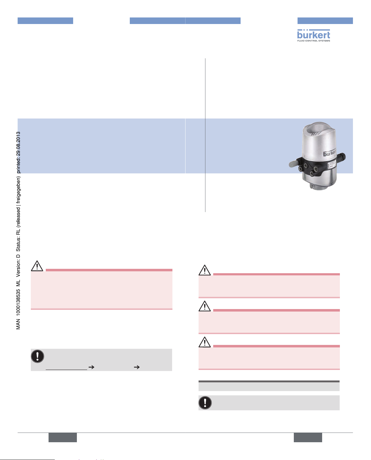
Type 8681
Control Head
Steuerkopf
Tête de commande
Quickstart
2
THE QUICKSTART1.
WARNING!
Important safety information!
Read quickstart carefully and thoroughly. Study in particular the chapters entitled 4. Basic Safety Instructions
and 3. Authorized use .
The operating instructions must be read and understood.•
Quickstart explains, for example, how to install and start-up
the device.
The detailed description of the device can be found in the
operating instructions for Control Head Type 8681.
The operating instructions can be found on the
Internet at:
www.burkert.com Documentation Type 8681
english
3
SYMBOLS2.
The following symbols are used in these instructions.
DANGER!
Warns of an immediate danger!
Failure to observe the warning will result in a fatal or •
serious injury.
WARNING!
Warns of a potentially dangerous situation!
Failure to observe the warning may result in serious •
injuries or death.
CAUTION!
Warns of a possible danger!
Failure to observe this warning may result in a moderate •
or minor injury.
NOTE!
Warns of damage to property!
Important tips and recommendations for safe and
the fl awless functioning of the device.
designates a procedure which you must carry out.
english
Page 2
4
3. AUTHORIZED USE
Non-authorized use of the Control Head Type 8681
may be a hazard to people, nearby equipment and
the environment.
The Control Head has been designed for use as •
actuation of pneumatically operated process valves
and / or for recording the switching states of these.
Use according to the authorized data, operating condi-•
tions and conditions of use specifi ed in the contract
documents and operating instructions.
In view of the large number of options for use it might •
be necessary to test prior to installation whether the
control head is suitable for the concrete use.
If you have any questions, please contact your Bürkert
Service Center.
The device may be used only in conjunction with third-•
party devices and components recommended and
authorized by Burkert.
Any unauthorized reconstructions and changes to the •
control head are prohibited for safety reasons.
Correct transportation, correct storage and installation •
and careful use and maintenance are essential for
reliable and faultless operation.
For connecting the control head, use line installations •
that do not cause any mechanical stresses.
Use the device only as intended.•
english
5
Predictable Misuse3.1.
Do not supply the medium connectors of the system with •
aggressive or fl ammable media.
Do not supply the medium connectors with any liquids.•
Do not physically stress the housing (e.g. by placing objects •
on it or standing on it, or using it as attachment point for
transport work).
Do not make any external modifi cations to the device •
housings. Do not paint the housing parts or screws.
In the explosion-risk area, only wipe the control head with a •
damp or anti-static cloth to avoid electro-static charges!
english
6
4. BASIC SAFETY
INSTRUCTIONS
These safety instructions do not make allowance for any
contingencies and events which may arise during the instal-•
lation, operation and maintenance of the devices.
local safety regulations - the operator is responsible for •
observing these regulations, also with reference to the
installation personnel.
DANGER!
Danger – high pressure!
Before loosening pneumatic lines and valves, turn off •
the pressure and vent the lines.
Danger of explosion in explosive atmosphere (only in
the event of a fault as zone 2)!
Opening the hood or the housing in an explosive atmo-•
sphere is only allowed in the isolated state!
WARNING!
Risk of electric shock!
Before reaching into the system (except for the •
Teach-In procedure in a non-explosive atmosphere)
switch off the power supply and secure it to prevent
english
7
restarting!
Observe applicable accident prevention and safety •
regulations for electrical equipment!
WARNING!
General Hazardous Situations.
To prevent injuries, ensure that:
the system cannot be activated unintentionally.•
installation and maintenance work, as well as operator •
control actions may be carried out by authorized, qualifi ed technicians only and with the appropriate tools.
after an interruption in the power supply or pneu-•
matic supply, ensure that the process is restarted in a
defi ned or controlled manner.
the device may be installed and operated only when in •
perfect condition and in consideration of the operating
instructions.
the general rules of technology apply to application •
planning and operation of the device.
english
Type 8681
Page 3
8
NOTE!
Electrostatic sensitive components / modules!
The device contains electronic components, which react •
sensitively to electrostatic discharge (ESD). Contact
with electrostatically charged persons or objects may
be hazardous to these components. In the worst case
scenario, they will be destroyed immediately or will fail
after start-up.
Observe the requirements in accordance with DIN EN •
61340-5-1 and 5-2 to minimize or avoid the possibility of
damage caused by sudden electrostatic discharge!
Also, ensure that you do not touch electronic components •
when the power supply voltage is present!
Control Head Type 8681 was developed with due
consideration given to accepted safety rules and
is state-of-the-art. Nevertheless, dangerous situations may occur.
Failure to observe this operating manual and its operating instructions as well as unauthorized tampering with
the device release us from any liability and also invalidate
the warranty covering the devices and accessories!
english
9
Explosive Atmosphere4.1.
NOTE!
Operation of the Control Head in Explosive
Atmosphere
The housing may not be opened when devices are •
charged! It should be secured against unintentional
opening using plastic self-cutting screws or seal (or
comparable)!
Layers of dust on the housing may not exceed 5 mm! •
Lint, conductive and non-conductive dust particles are
allowed.
The inside of the housing may not be dirty!
Activating the DIP switches on the circuit board, using •
the service plug and the Teach buttons is not allowed in
explosive atmosphere!
english
10
GENERAL INFORMATION5.
Scope of Supply5.1.
Check immediately upon receipt of the delivery that the contents are not damaged and that the type and scope agree
with the delivery note and packing list.
If there are any discrepancies, please contact us immediately.
Contact address5.2.
Germany:
Bürkert Fluid Control Systems
Sales Center
Christian-Bürkert-Straße 13-17
D-74653 Ingelfi ngen
Tel.: +49 7940 10 91 111
Fax: +49 7940 10 91 448
E-mail: info@de.buerkert.com
International:
The contact addresses can be found on the Internet at:
www.burkert.com
Bürkert Company Locations
english
11
STRUCTURE AND FUNCTION6.
The Control Head Type 8681 has been designed for use
as actuation of pneumatically operated process valves and/
or for recording the switching states of these.
For the recording and feedback of the process valve
switching positions to a higher-level control, the control
head has been equipped with a contactless position measuring system, which works with three discrete, adjustable
feedback signals (Teach-In Function).
Various pneumatic and electrical connection variants are
available.
Positions and status information can be indicated by means
of three signal colors.
Manual Control6.1.
Standardly, the control head provides the following:
a magnetic manual control that is easily accessible from •
the outside on the basis of encoded magnetic fi elds for
Solenoid Valve 1 (Connection 2/A1), as well as
a mechanical manual control accessible when the hood •
is open on each equipped solenoid valve.
english
Type 8681
Page 4
12
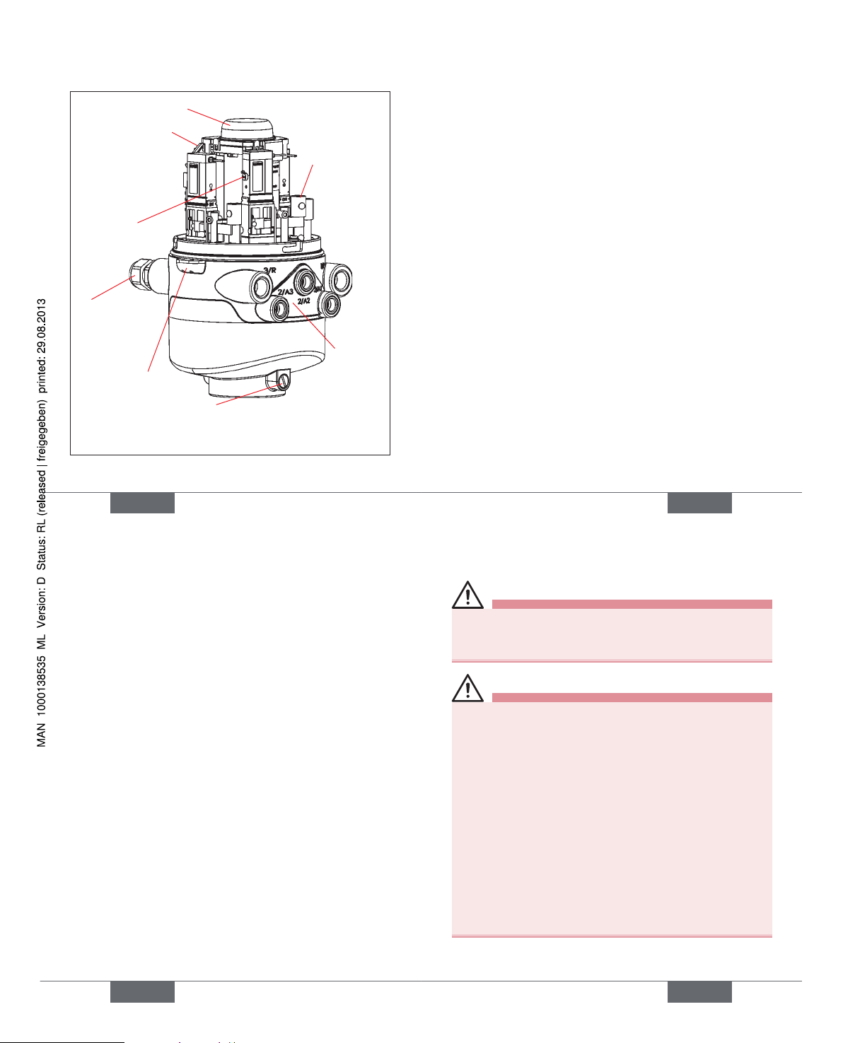
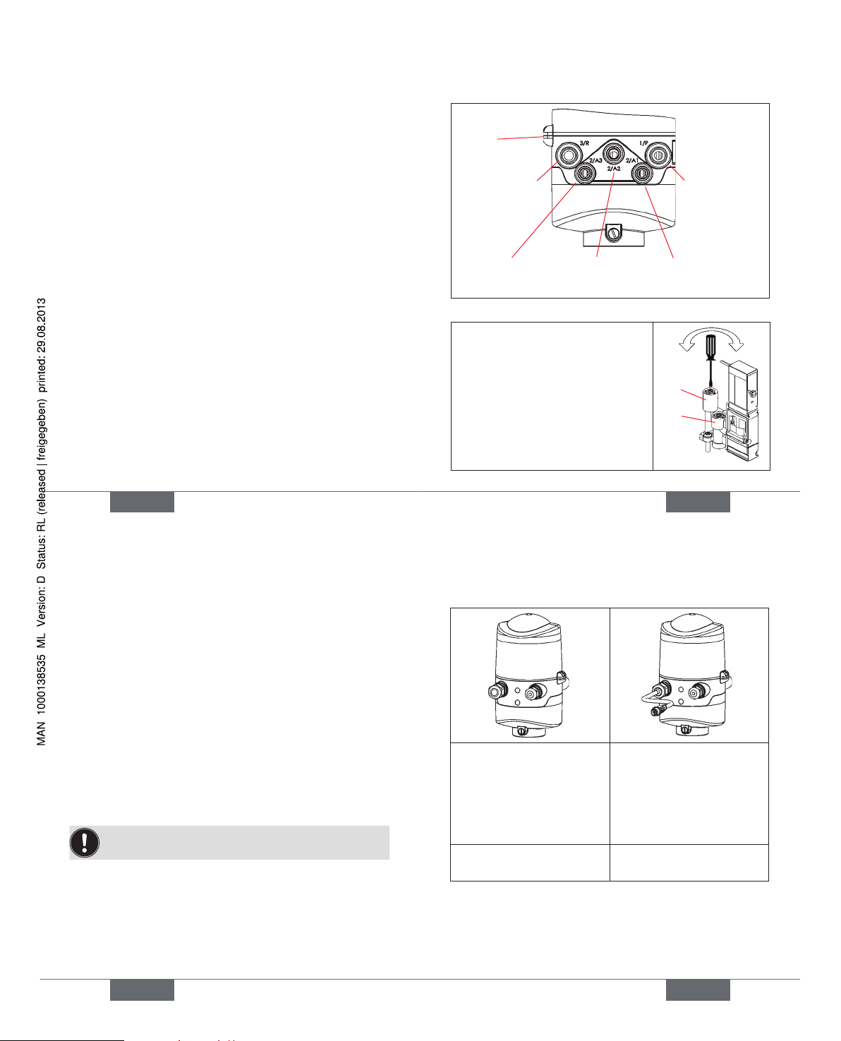
Structure6.2.
Pneumatic
connections
Locking/(shoulder) screws
as protection against pulling
off from the hub fl ange
Electrical
connections
(Cable
glands)
Sealing lug
Electronics module
(24VDC- or AS-iDesign with service
interface, connection
terminals, DIP, TeachIn-buttons)
Position measuring system with LED’s
Flow restriction
screw(s) of
solenoid valves
Mechanical
manual control
at solenoid
valves (red
levers)
english
13
TECHNICAL DATA7.
Operating Conditions7.1.
Ambient temperature: -10 ... +55 °C
Protection class: IP65 / IP67 according to EN 60529 or
IP69K according to IEC 40050-9
Mechanical Data7.2.
Dimensions: see data sheet
Housing material: outside: PA, PP, PPO, VA
inside: ABS, PA, PMMA
Sealing material: outside: CR, EPDM
inside: EPDM, FKM, NBR
Pneumatic Data7.3.
Control medium: Oil-free and dry air, neutral gases,
Quality classes in accordance with
DIN ISO 8573-1 (5 µm fi lter
recommended)
Dust content: max. particle size 40 µm,
(quality class 5) max. particle density 10 mg/m
3
Water content: max. pressure dew point -20 °C or
(quality class 3) min. 10 °C below the lowest
operating temperature
english
14
Oil content: max. 25 mg/m
3
(quality class 5)
Temperature range
of compressed air: -10 to +50 °C
Pressure range: 2.5 to 8 bar
Air rate of solenoid
valve: 110 I
N
/min (for de-/aeration, ventilation)
(110 IN/min - supplied state
200 IN/min - maximum typical fl ow-rate)
(QNn value according to defi nition for
pressure drop from 7 to 6 bar absolute
at +20 °C)
Connections: Intake and exhaust air connection G1/4
Working connections G1/8
Position Measuring System Data7.4.
Stroke range: 0 ... 80 mm (measuring range)
Resolution: 0.1 mm
Total fault:
± 0.5 mm - when using a target as
mentioned in the manual
Electrical Data7.5.
see chapter 9. 24 V DC - Design or 10. AS-I - Design or
11. DeviceNet- Design or 12. 120 V AC - Design .
english
15
ASSEMBLY / INSTALLATION8.
DANGER!
Risk of injury from high pressure in the equipment!
Before loosening pneumatic lines and valves, turn off •
the pressure and vent the lines.
WARNING!
Risk of injury due to electrical shock!
Before reaching into the system (except for the •
Teach-In procedure in a non-explosive atmosphere)
switch off the power supply and secure it to prevent
restarting!
Observe applicable accident prevention and safety •
regulations for electrical equipment!
Risk of injury from improper installation!
Installation may be carried out by authorized techni-•
cians only and with the appropriate tools!
Risk of injury from unintentional activation of the
system and an uncontrolled restart!
Secure system from unintentional activation.•
Following assembly, ensure a controlled restart.•
english
Type 8681
Page 5
16
Assembly8.1.
For the installation of the Control Head Type 8681 to a
process valve, you will require a process valve-specifi c hub
fl ange as an adapter. The hub fl ange must be adapted to
the design of the process valve.
Mount the piston rod with the target on the process
valve spindle. Observe reference dimensions!
Fasten the hub fl ange on the process valve.
During this, observe central alignment and sealing
conditions!
Check the secure fi t of the sealing rings (in the upper
and lower grooves).
Mount the control head on the hub fl ange (seamlessly
360° rotatable).
Secure the control head with the two locking screws
(shoulder screws M5) in the middle grove of the hub
fl ange (see operating instructions).
Pneumatic Installation8.2.
Connect the required working connections 2/A1 to 2/
A3 (each according to model) with the corresponding
connections on the process valve.
Connect the supply line to supply pressure connection
1/P (2.5 to 8 bar).
english
17
A silencer has already been mounted on the Exhaust
Air Connection (3/R) in the supplied state.
1/P
Supply pressure
connection
3/R
Exhaust air
connection
(Silencer)
2/A3: SV 3 2/A2: SV 2 2/A1: SV 1
2/A1 ... A3 - Working connections - Solenoid valves (SV)
Sealing lugs
at the
housing
The fl ow restriction screws
R and P of the solenoid valves
(see operating instructions) are
used for setting the air intake and
exhaust for the working connections (for setting of the control
speed of the process valves).
R
P
open close
english
18
Opening and Closing the 8.3.
Housing
Opening:
Loosen plastic self-cutting screws or seal, if housing
has been secured.
Open the plastic hood by turning counterclockwise (all
the way, approx. 1.5 cm).
Closing:
Put the plastic hood on the lower part such that the
inner lugs are positioned over the fastening grooves
and the external sealing lugs are positioned almost over
each other. Press the hood completely over the seal of
the lower part.
Turn the hood by approx. 1.5 cm clockwise (meaning
until the sealing lugs are positioned over each other).
A seal or a hood safeguard using plastic self-cutting
screws is required in the explosion-risk area!
Electrical Installation8.4.
see chapter
9. 24 V DC - Design , 10. AS-I - Design ,
11. DeviceNet- Design or 12. 120 V AC - Design .
english
19
9. 24 V DC - DESIGN
Connection options9.1.
left: 1 x M16 x 1,5 cable
gland
for power supply and
signals
left: 1 x M16 x 1,5 cable
gland with multi-pole
connection (M12 plug
according to IEC 610762-101, 12-pole) on a cable
of 8 cm length
right: 1 x M16 x 1,5 cable
gland for external initiator
right: 1 x M16 x 1,5 cable
gland for external initiator
english
Type 8681
Page 6
20
Electrical Data9.2.
Power supply: 12 ... 28 V DC, residual ripple 10 %
Power consumption:
(standby current): 30 mA at 24 V DC
Solenoid valves:
Power input per max. 0.8 W
solenoid valve: (0.9 W during activation)
Operating mode: Long-term operation (100 %)
Central display of the
switching states: 42 mA with a power supply of
24 V DC per illuminated display;
Outputs/binary
feedback signals: S1 out - S4 out
Design: Normally open contact, PNP output
short-circuit-proof, with self-clocking
short-circuit protection
Switchable
output current: max. 100 mA per feedback signal
Option: Analog feedback signal:
Signal output: S3 out (binary feedback signal
S3out not available)
Type: Current source (4 to 20 mA)
english
21
Input / proximity switches (external initiator: S4 in):
Power supply:
Voltage present at control head - 10 %
Current carrying
capacity, sensor
power supply: max. 90 mA;
short-circuit protection
Design: DC 2- and 3-conductor, NO or NC
(factory setting NO), PNP output
Valve control inputs (Y1 - Y3):
Signal level - active: U > 10 V, max. 24 V DC + 10 %
Electrical Installation 9.3. (24 VDC)
WARNING!
Risk of injury due to electrical shock!
Before reaching into the system (except for the •
Teach-In procedure in a non-explosive atmosphere)
switch off the power supply and secure it to prevent
restarting!
Observe applicable accident prevention and safety •
regulations for electrical equipment!
Risk of injury from improper installation!
Installation may be carried out by authorized techni-•
cians only and with the appropriate tools!
english
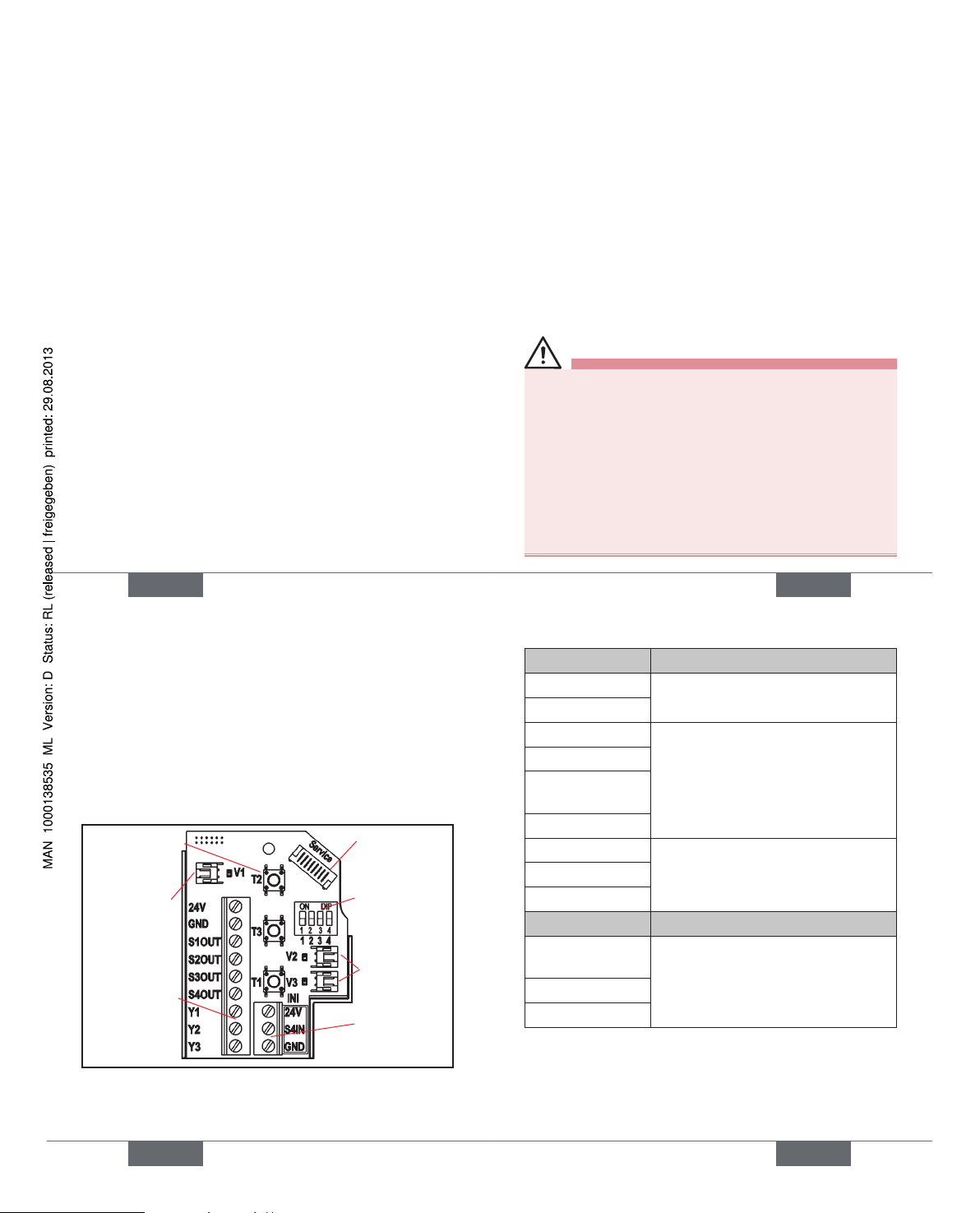
22
Cable glands:
Open the housing.
Assemble connection cables for signals and power
supply as well as for the external initiator.
Insert cables through the respective cable glands into
the interior of the housing.
Secure the wires to the terminal strips according to the
pin assignments depicted in the fi gure.
Solenoid valve
connection
with status
LED for SV1
Terminal strip 1
Service
interface
DIP switches
for color
coding the
LED‘s
Terminal strip 2
(for external
initiator)
Teach-Inbuttons T1-3
SV-connections
with status LED
for SV2, 3
english
23
Terminal strip 1 Confi guration
24 V Power supply 24 V
GND GND
S1 OUT Output position 1
S2 OUT Output position 2
S3 OUT Output position 3
(Option: analog signal)
S4 OUT Output external initiator
Y1 Input solenoid valve 1
Y2 Input solenoid valve 2
Y3 Input solenoid valve 3
Terminal strip 2 Confi guration
24 V Power supply 24 V for external
initiator
S4 IN Input external initiator
GND GND external initiator
Close the housing
.
Ensure IP protection (dummy plugs)!
english
Type 8681
Page 7
24
Cable gland with Multi-pole connection:
Internal cabling work is not required for models with multi-pole
connection. But you will require the correspondingly
assembled cable sets with the following pin assignments:
Pin Description Confi guration
1 24 V Power supply 24 V
2 GND GND
3 S1 OUT Output position 1
4 S2 OUT Output position 2
5 S3 OUT Output position 3
(Option: analog signal)
6 S4 OUT Output external initiator
7 Y1 Input solenoid valve 1
8 Y2 Input solenoid valve 2
9 Y3 Input solenoid valve 3
10-12
not used
An external initiator can be connected using the small 3-pin
terminal strip 2 (see fi gure on page 22 or manual, chapter
„Connection of an external initiator“).
english
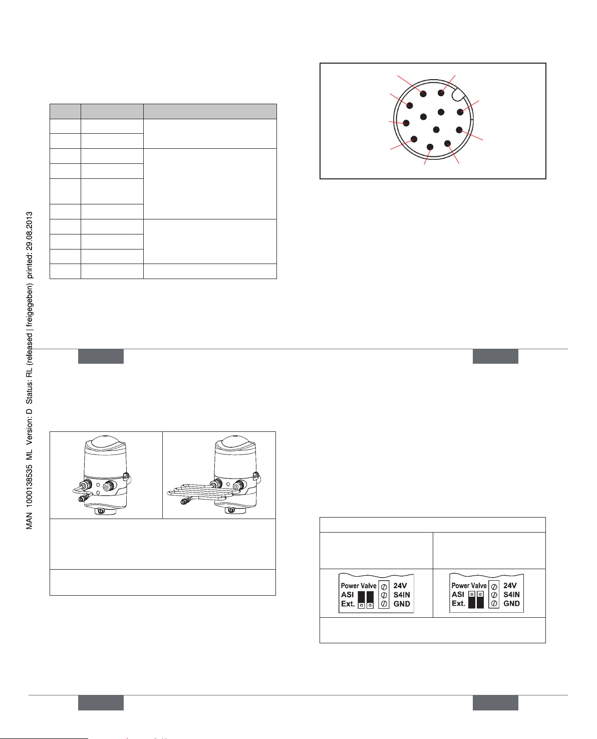
25
Input and output signals to the higher-level control (PLC):
Pin 9 - Y3
Pin 8 - Y2
12
Pin 6 - S4 out
Pin 7 - Y1
Pin 1 - 24 V
Pin 5 - S3 out
Pin 4 - S2 out
11
Pin 3 - S1 out
Pin 2 - GND
10
(12-pole circular plug-in connector M12 x 0.75 - male,
acc. to IEC 61076-2-101 — view onto the plug pins)
english
26
10. AS-I - DESIGN
Connection options10.1.
left connection:
1 x M16 x 1,5 cable gland with Multi-pole connection
(M12 plug according to IEC 61076-2-101, 4-pole) on a
cable of 8 or 80 cm length
right connection:
1 x M16 x 1,5 cable gland for external initiator
Maximum Length of the Bus 10.2.
Line
The bus cable may be a maximum of 100 m long. When
designing the system, consider the length of the round cable
leading directly to the control head (see example calculation
in the operating instructions).
english
27
Number of Connectable 10.3.
Control Heads
In AS interface versions with extended addressing range
(A/B slave), 1 master can communicate with 62 slaves.
In AS interface versions with addressing range 31 slaves a
maximum of 31 control heads can be connected to a bus line
(the address range restriction).
10.4. Electrical Data
Power supply:
Standard: via AS-i
(29,5 ... 31,6 V DC
acc. specifi cation)
Option: externally
(19,2 V DC to 31,6 V DC)
Setting the valve’s power supply using jumpers on the
AS-interface electronics module.
Input / proximity switches (external initiator: S4 in):
Power supply: AS interface voltage present at
control head - 10 %
english
Type 8681
Page 8
28
Current carrying capacity,
sensor power supply: max. 30 mA;
short-circuit protection
Design: DC 2- and 3-conductor, NO or
NC (factory setting NO), PNP
output
Inputs (from master
perspective): 3 binary feedback signals and
external initiator
Outputs (from master
perspective): 0 to 3 solenoid valves
Switching capacity: max. 0.8 W via AS interface
Pull-in current: 30 mA or 0.9 W / 200 ms
Operating mode: Long-term operation (100 %)
Central display of the switching states:
Power consumption: max. 33 mA or 1 W per illumi nated display (at 30.5 V AS interface voltage)
Power supply via AS interface bus:
Power consumption
from AS interface: max. 200 mA (incl. external
initiator with 30 mA)
Integrated short-circuit protection
english
29
External Power Supply:
Ext. power supply: 19.2 V DC to 31.6 V DC
Max. power consumption
from external power supply: 110 mA at 24 V DC
Integrated short-circuit protection
Electrical Installation (AS-i)10.5.
WARNING!
Risk of injury due to electrical shock!
Before reaching into the system (except for the •
Teach-In procedure in a non-explosive atmosphere)
switch off the power supply and secure it to prevent
restarting!
Observe applicable accident prevention and safety •
regulations for electrical equipment!
Risk of injury from improper installation!
Installation may be carried out by authorized techni-•
cians only and with the appropriate tools!
Internal cabling work is not required for any of the AS Interface
designs with multi-pole connection. However, you will require
the correspondingly assembled cable sets with the following
pin assignments.
english
30
Pin 2
Pin 3
Pin 1
Pin 4
Likewise, the jumpers on the electronics module must be set
correspondingly (power supply via AS-i or externally) - see
page 27 .
Power supply
Pin
(via AS-i)
Confi guration
(externally)
Confi guration Color
1 AS-i+ AS-i+ brown
2 not used GND white
3 AS-i- AS-i- blue
4 not used 24 V+ black
An external initiator can be connected using the small
3-pin terminal strip 2 - see manual, chapter „Connection of
an external initiator“.
english
31
11. DEVICENET- DESIGN
Connection11.1.
left connection:
1 x M16 x 1,5 cable gland with Multi-pole connection
(M12 plug according to IEC 61076-2-101, 5-pole) on a
cable of 80 cm length
right connection:
1 x M16 x 1,5 cable gland for external initiator
DeviceNet Specifi cation11.2.
EDS fi le 8681.EDS
Icons 8681.ICO
Baud rate Factory setting: 125 kBit/s
Address Factory setting: 63
english
Type 8681
Page 9
32
Process data 2 static input assemblies
(Input: from the control head to the
DeviceNet Master/Scanner)
1 static output assembly
Inputs 3 discrete feedback signals of the posi-
tion measuring system (pos. S1 - S3)
1 discrete feedback signal of the
external initiators (S4)
1 analog position signal in mm
Supply via DeviceNet string
(11 to 25 V DC)
Switch level high signal 5 V
Switch level low signal 1,5 V
Outputs 3 solenoid valves
Power consumption
from the bus: max. 5 W, (3 valves with each 0,8 W)
Length of the Bus line11.3.
The maximum total line length (sum of trunk lines and drop
lines) of a network depends on the baud rate.
The maximum total line length (according to DeviceNet
specifi cation) is for:
english
33
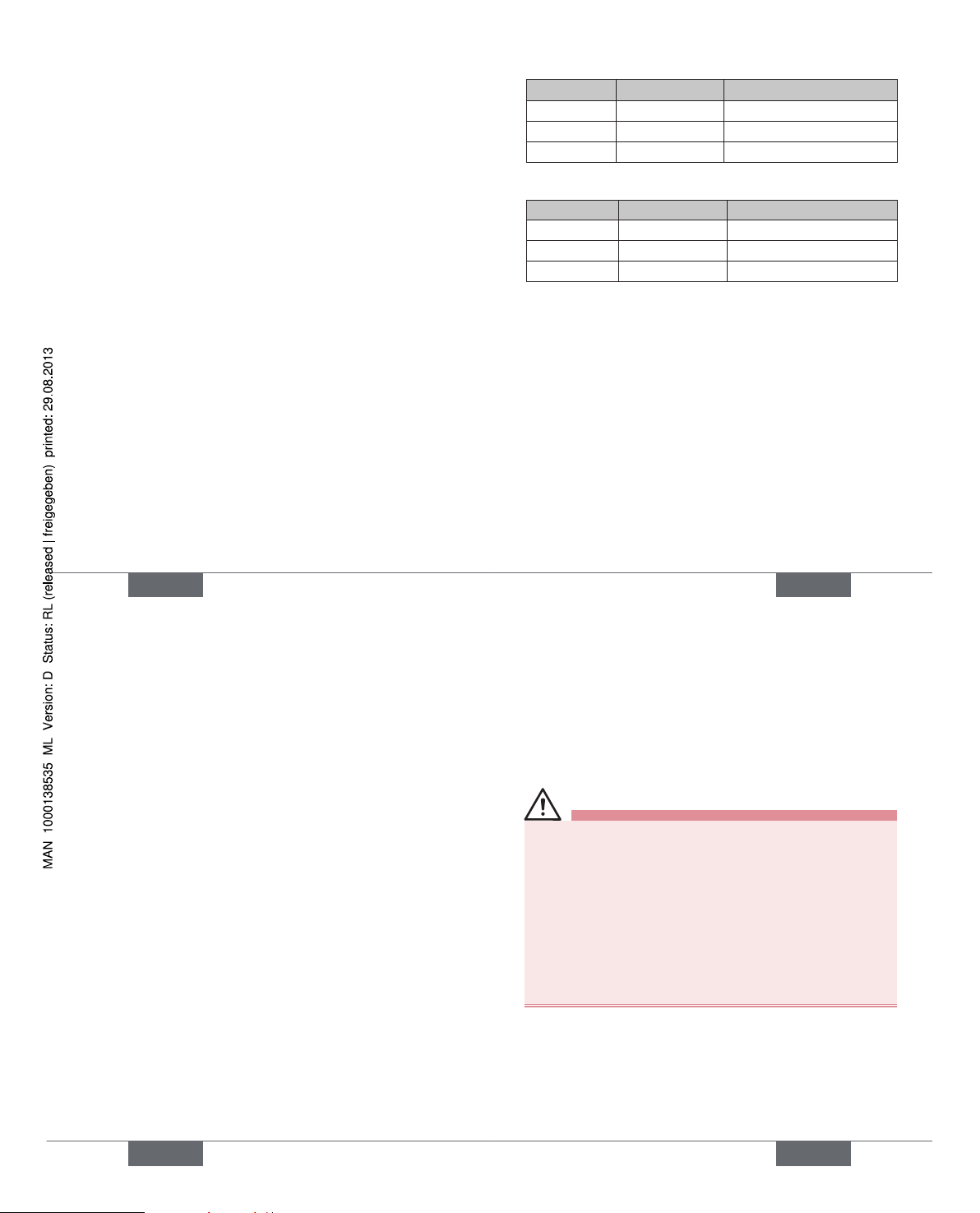
Baud rate Thick Cable Thin Cable
125 500 m 100 m
250 250 m 100 m
500 100 m 100 m
The maximum drop line length is for:
Baud rate Drop Line Sum (in Network)
125 6 m 156 m
250 6 m 78 m
500 6 m 39 m
Electrical Data11.4.
Electrical power supply: 11 to 25 V DC (according to
specifi cation)
Max. power consumption: 200 mA at 24 V DC
Input / proximity switches (external initiator: S4 in):
Power supply: via DeviceNet power
supply - 10 %
Current carrying capacity
sensor power supply: max. 30 mA
Short-circuit protection
Design: DC 2- and 3-conductor,
NO contact, PNP output
english
34
Input current 1 signal: I
Sensor
> 6.5 mA, limited
internally to 10 mA
Input voltage 1 signal: U
Sensor
> 10 V
Input current 0 signal: I
Sensor
< 4 mA
Input voltage 0 signal: U
sensor
< 5 V
Inputs (from master perspective) / binary or analog
feedback signals:
The recovery of the 3 valve positions reported back binarily
or of the analog position signalis described in the manual,
chapter “Position Mesuring System”.
Outputs (from master perspective) / solenoid valves:
max. switching capacity 1.0 W
typ. continuous output 0.8 W
Output reduction integrated via DeviceNet
interface electronics
pull-in current 120 mA typ. / 200 ms
(3 valves)
Holding current 100 mA typ. at 24 V DC
(3 valves)
Operating mode Long-term operation
(100 % operation)
Valve types 6524
Central display of the switching states:
Power consumption from
DeviceNet at 24 V DC 42 mA with 24 V DC power
english
35
supply per illuminated display
shown; Color switching see
in the manual, chapter “LED -
Color Assignments”
Electrical Installation (DVN)11.5.
WARNING!
Risk of injury due to electrical shock!
Before reaching into the system (except for the •
Teach-In procedure in a non-explosive atmosphere)
switch off the power supply and secure it to prevent
restarting!
Observe applicable accident prevention and safety •
regulations for electrical equipment!
Risk of injury from improper installation!
Installation may be carried out by authorized techni-•
cians only and with the appropriate tools!
No internal cabling work is required for any of the DeviceNet designs.
However, you will require the correspondingly assembled
cable sets with the pin assignments described below:
english
Type 8681
Page 10
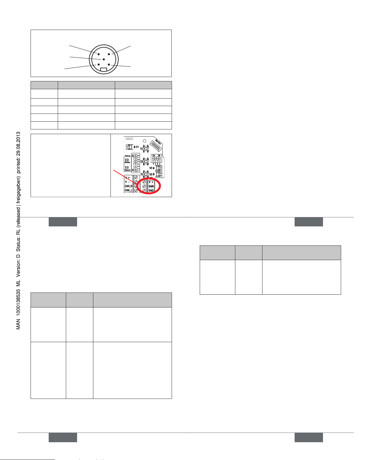
36
Pin 4: CAN_H
Pin 5: CAN_L
Pin 1: Drain
Pin 3: V–
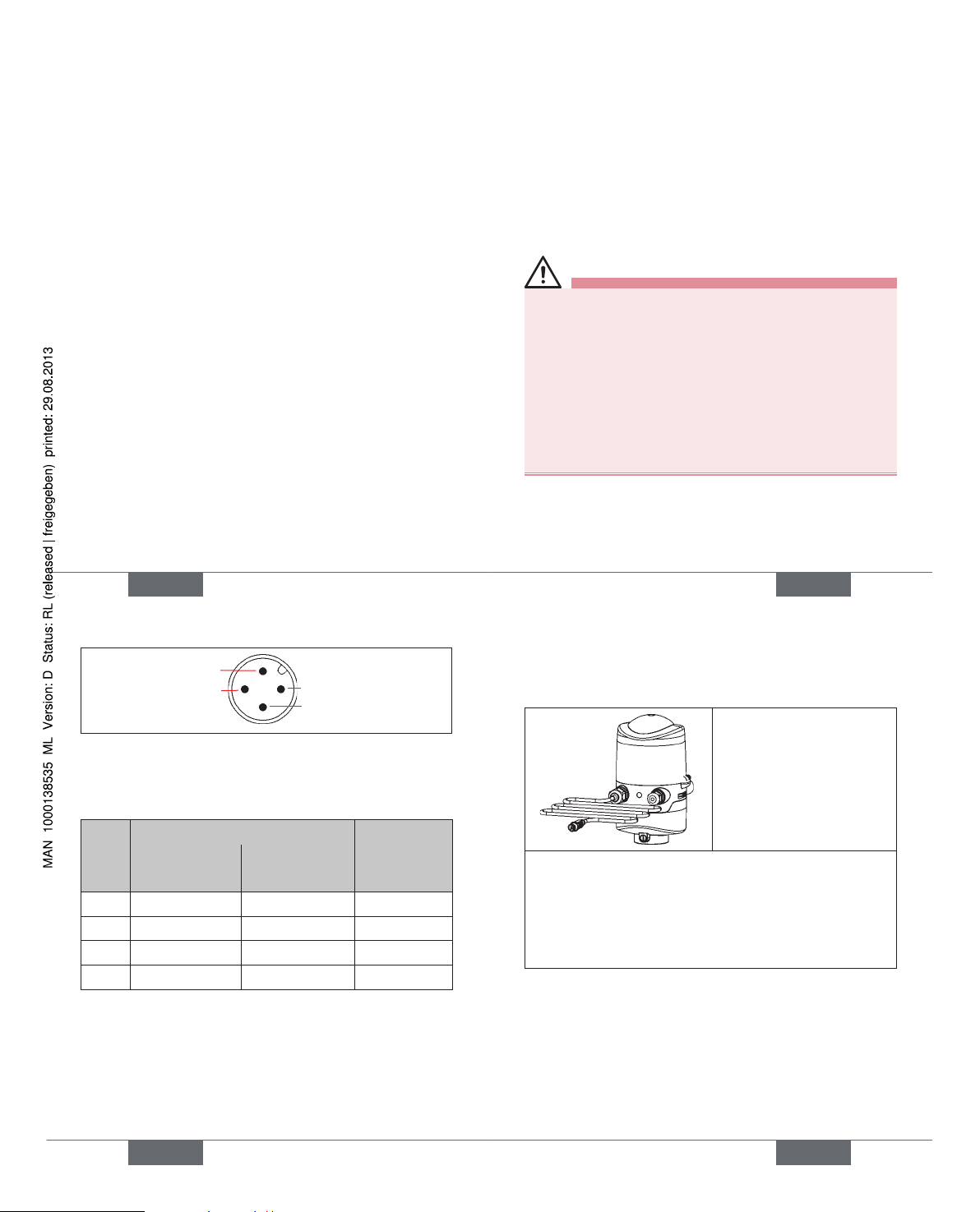
Pin 2: V+
View of plug from the front onto the pins:
Pin Signal Color
1 Drain
(shield)
2 V+ red
3 V- black
4 CAN_H white
5 CAN_L blue
An external initiator can be
connected using the small
3-pin terminal strip - see
manual, chapter „Connection
of an external initiator“.
english
37
Network Topology11.6.
When installing a DeviceNet system, ensure that the terminating circuit of the data lines is correct. The circuit prevents
the occurrence of interference caused by signals refl ected
onto the data lines.
The trunk line must be terminated at both ends with
resistors of 120
Ω and 1/4 W power loss (see the manual,
chapter „Network Topology of a DeviceNet System“).
Confi guring the Baud rate 11.7.
and DVN address
8 DIP switches are available for confi guration:
DIP switches 1 to 6 for DeviceNet address•
(factory setting: 63, i.e. DIP 1 - 6: on)
DIP switches 7 to 8 for Baud rate•
(factory setting: 125, i.e. DIP 7 + 8: off)
Further confi guring - see manual, chapter „Confi guring the
DeviceNet address / baud rate“
english
38
Confi guration of Process Data11.8.
To transmit process data via an I/O connection, 2 static
input and 1 static output assembly can be selected, see
manual, chapter “Confi guration of Process Data”
„Address“ in the table describes the data attribute of the
assemblies for read access (class, instance, attributes).
InputAssemblies
Address Format of the Data attribute
value 0: OFF / value 1: ON
S1…S4
(factory
setting)
4, 1, 3 Byte 0:
Bit 0: position S1
Bit 1: position S2
Bit 2: position S3
Bit 3: position S4
S1…S4 +
POS
(with POS:
current
position)
4, 2, 3 Byte 0:
Bit 0: position S1
Bit 1: position S2
Bit 2: position S3
Bit 3: position S4
Bit 4…7: not used
Byte 1:
POS in mm
„Address“ in the table describes the data attribute of the
assemblies for read access (class, instance, attributes).
english
39
OutputAssembly
Address Format of the Data attribute
value 0: OFF / value 1: ON
Solenoid
valve
SV 1 ... 3
4, 21, 3 Byte 0:
Bit 0: SV1
Bit 1: SV2
Bit 2: SV3
Bit 3…7: not used
Confi guration of the Safety 11.9.
Position of Solenoid Valves if
Bus Error
If the bus fails, the solenoid valve is switched to a programmable safety position (factory setting: the solenoid valve
is in the power-off-state) - for details see manual, chapter
„Confi guration of the device“.
The bus status LED „Network“ on the electronic module
specifi es the kind of error by color and blinking pattern - for
details see manual, chapter „Display of the Status LEDs in
the event of a bus error“).
english
Type 8681
Page 11
40
120 V AC - DESIGN12.
Connection 12.1.
left connection:
1 x M16 x 1,5 cable gland for
power supply and signals
right connection:
1 x M16 x 1,5 cable gland for
external initiator
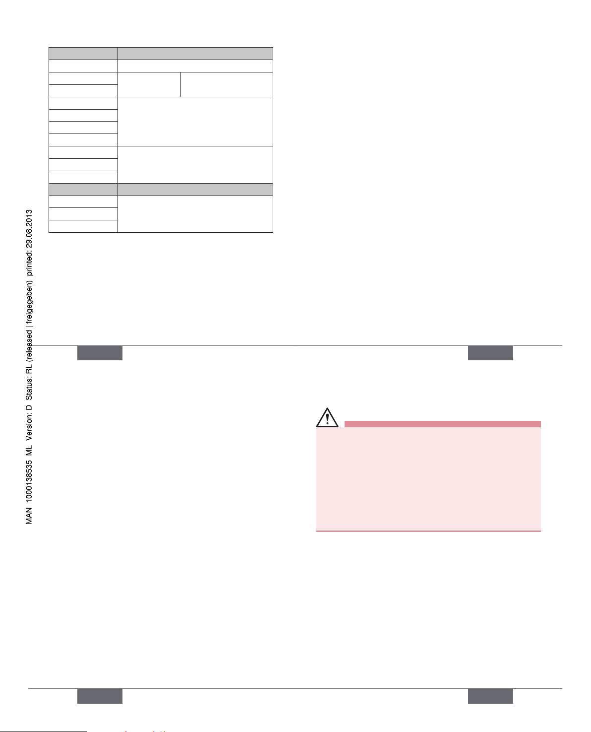
Electrical Data12.2.
Central power supply: 110 ... 130 V AC, 50/60 Hz
Power consumption
(stnd-by current): 10 mA at 120 V AC
Solenoid valves:
power consumption
per solenoid valve: max. 1,4 VA
(1,7 VA during activation)
power consumption
per solenoid valve: 12 mA at 120 V AC
Operation mode: Long-term operation (100 %)
english
41
Central display of the switching states:
13 mA with a power supply of
120 V AC per illuminated display
Outputs/binary
feedback signals: S1out - S3out
Design: NO contact, L switching,
short-circuit protection via auto matically resetting fuse
switchable output
current: max. 50 mA per feedback signal
Output voltage
- active: (operating voltage - 2 V)
- inactive: max. 1 V in unloaded state
Feedback signal output: S4 out is directly connected to
S4 in
Input / proximity switches (external initiator: S4 in):
Power supply: voltage present at control head
U
Nominal
= 120 V AC, 50/60 Hz
Current carrying capacity,
sensor power supply: max. 0.7 A
Short-circuit protection
Design: DC 2- and 3-conductor,
NO contact, L-switching
input current 1-Signal: I
Sensor
< 2 mA
english
42
Valve control inputs (Y1 - Y3):
Signal level - active: U > 60 V AC
Signal level - inactive: U < 20 V AC
Impedance: > 40 kOhm
Electrical Installation12.3.
WARNING!
Risk of injury due to electrical shock (120 V AC)!
When setting the position measuring system •
(Teach-In), do not contact any live components!
Before reaching into the system (except for the •
Teach-In procedure in a non-explosive atmosphere)
switch off the power supply and secure it to prevent
restarting
Observe applicable accident prevention and safety •
regulations for electrical equipment!
Risk of injury from improper installation!
the • PE connection must be connected!
Installation may be carried out by authorized techni-•
cians only and with the appropriate tools!
english
43
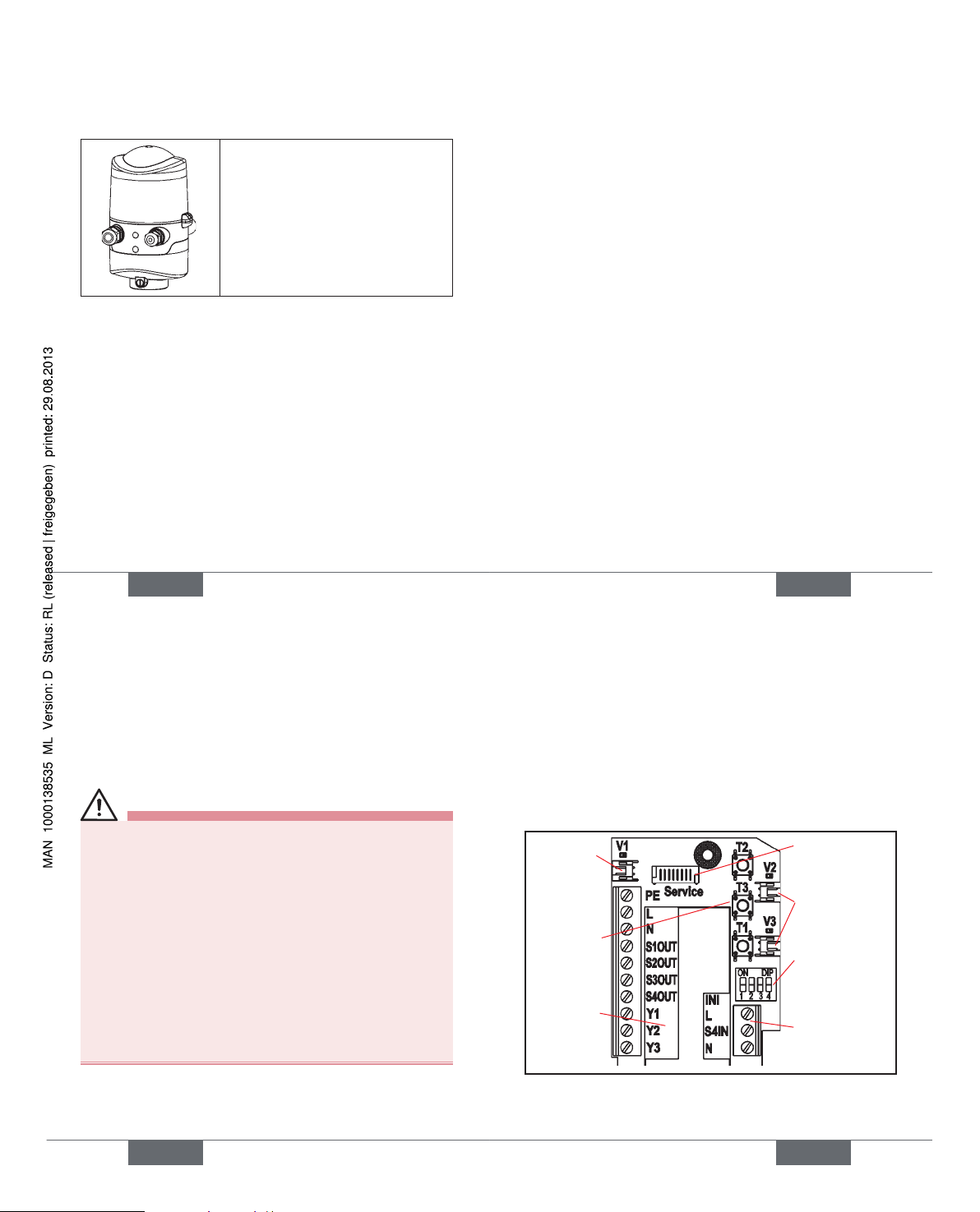
Cable gland:
Open the housing.
Assemble connection cables for signals and power
supply as well as for the external initiator.
Insert cables through the respective cable glands into
the interior of the housing.
Connect the wires to the connection terminals
according to the pin assignment described in the
fi gure. Fix them.
connection
for valve 1
with status
LED
terminal
strip 1
service
interface
DIP-switches
for color
coding the
LED‘s
terminal strip 2
(external
initiator)
Teach-In-
buttons
T1-3
connections for
valve 2, 3 with
status LED
english
Type 8681
Page 12
44
Terminal strip 1 Confi guration
PE Protection Earth - protective conductor
L
Power supply
120 V AC
live conductor
N neutral conductor
S1 OUT Ouput position 1
S2 OUT Ouput position 2
S3 OUT Ouput position 3
S4 OUT Ouput external initiator
Y1 Input solenoid valve 1
Y2 Input solenoid valve 2
Y3 Input solenoid valve 3
Terminal strip 2 Confi guration (external initiator)
L Power supply - live conductor
S4 IN Input external initiator
N Power supply - neutral conductor
Close the housing.
Ensure IP protection (dummy plugs).
An external initiator can be connected using the small
3-pin terminal strip 2 - see manual, chapter „Connection of
an external initiator“.
english
45
POSITION MEASURING 13.
SYSTEM
The recordable stroke range is between 0 and 80 mm.
Three Teach-In buttons have been provided for comparison
with the actual stroke range.
Teach-In13.1.
Open the housing.
Supply electrical power.
Position the process valve at the lower switching
position.
Depress the lower Teach-In button (T1) for approx. 1.5
seconds (the LED corresponding to this position will
fl ash quickly three times during the teaching phase).
Once this position has been stored, the corresponding
LED will remain continuously lit until the position of the
piston is changed.
Afterwards, position the process valve at the upper
switching position to be recorded.
Depress the upper Teach-In button (T2) for approx. 1.5
seconds (the LED corresponding to this position will
fl ash quickly three times during the teaching phase).
Once this position has been stored, the corresponding
LED will remain continuously lit until the position of the
piston is changed.
english
46
The process valve can now be moved into a third,
defi ned position.
Depress the middle Teach-In button (T3) for approx.
1.5 seconds (the LED corresponding to this position
will fl ash quickly three times during the teaching
phase).
Once this position has been stored, the corresponding
LED will fl ash continuously until the position of the
piston is changed.
If necessary, return control head and system to normal
state (switching position, power supply).
Close the housing.
Teach-Reset13.2.
Depress the Teach-In button ( T1+T2) for ca. 2.5 sec.
(optical feedback: Blinking in the fault color)
Autotune13.3.
Autotune functions and Autotune sequences - see operating instructions.
LED - Color Assignments13.4.
S1 - green, continuously lit,
S2 - yellow, continuously lit,
S3 - green, continuously fl ashing (250 ms/250 ms)
(Delivered state of the DIP switches: 0000)
english
47
START-UP14.
WARNING!
Risk of injury from improper operation!
Improper operation may cause injury and damage to the
device and its environment.
Before starting-up must be ensured that the contents •
of the manual operator is known and understood.
The safety instructions and the intended use must be •
followed.
Only adequately trained personnel should take the •
plant / the device in operation.
Assembly of the control head type 8681.
Pneumatic and electrical installation.
S etting the position measuring system (Teach-In).
After assembly, installation and setting of the position measuring system according to the operating instructions the
control head is ready for operation.
english
Type 8681
Page 13

48
PACKAGING, TRANSPORT, 15.
STORAGE, DISPOSAL
NOTE!
Transport / storage damage!
Inadequately protected equipment may be damaged
during transport or storage.
Protect the device during transportation / storage •
against moisture and dirt in shock-resistant packaging.
Avoid the effects of heat and cold which could result •
in temperatures above or below the permitted storage
temperature.
Storage temperature: -20 ... +65 °C.•
NOTE!
Damage to the environment caused by device components contaminated with media.
Observe the relevant disposal and environmental pro-•
tection regulations.
Dispose of the device and packaging in an environmen-
tally friendly manner.
Observe national waste disposal regulations .
english
Type 8681
Page 14

www.burkert.com
We reserve the right to make
technical changes without notice.
Technische Änderungen
vorbehalten.
Sous réserve de modifi cations
techniques.
© 2010 - 2011 Bürkert Werke GmbH
Operating Instructions
1105/02_EU-ml_00806166
/ Original DE
Typ 8681
Steuerkopf
Quickstart
Deutsch
50
DER QUICKSTART1.
WARNUNG!
Wichtige Informationen zur Sicherheit!
Lesen Sie den Quickstart sorgfältig durch. Beachten Sie
vor allem die Kapitel Grundlegende Sicherheitshinweise
und Bestimmungsgemäße Verwendung.
Der Quickstart muss gelesen und verstanden werden.•
Der Quickstart erläutert beispielhaft die Montage und Inbetriebnahme des Gerätes.
Die ausführliche Beschreibung des Gerätes fi nden Sie in
der Bedienungsanleitung für den Typ 8681.
Die Bedienungsanleitung fi nden Sie im Internet:
www.buerkert.de Dokumentation Typ 8681
deutsch
51
DARSTELLUNGSMITTEL2.
In dieser Anleitung werden folgende Darstellungsmittel
verwendet.
GEFAHR!
Warnt vor einer unmittelbaren Gefahr!
Bei Nichtbeachtung sind Tod oder schwere Verletzun-•
gen die Folge.
WARNUNG!
Warnt vor einer möglicherweise gefährlichen Situation!
Bei Nichtbeachtung können schwere Verletzungen oder •
Tod die Folge sein.
VORSICHT!
Warnt vor einer möglichen Gefährdung!
Nichtbeachtung kann mittelschwere oder leichte Verlet-•
zungen zur Folge haben.
HINWEIS!
Warnt vor Sachschäden!
Wichtige Tipps und Empfehlungen.
markiert einen Arbeitsschritt den Sie ausführen müssen.
deutsch
Page 15

52
BESTIMMUNGSGEMÄSSE 3.
VERWENDUNG
Bei nicht bestimmungsgemäßem Einsatz des
Steuerkopfes Typ 8681 können Gefahren für Personen, Anlagen in der Umgebung und die Umwelt
entstehen.
Der Steuerkopf ist konzipiert für den Einsatz als An-•
steuerung pneumatisch betätigter Prozessventile und /
oder für die Erfassung von deren Schaltzuständen.
Für den Einsatz sind die in den Vertragsdokumenten •
und der Bedienungsanleitung spezifi zierten zulässigen Daten, Betriebs- und Einsatzbedingungen zu
beachten.
Angesichts der Vielzahl von Einsatz- und Verwen-•
dungsfällen muss vor dem Einbau geprüft und erforderlichenfalls getestet werden, ob der Steuerkopf für
den konkreten Einsatzfall geeignet ist:
Wenden Sie sich bei Unklarheiten an Ihr Bürkert Service Center.
Das Gerät nur in Verbindung mit von Bürkert empfoh-•
lenen bzw. zugelassenen Fremdgeräten und -komponenten einsetzen.
Eigenmächtige Umbauten und Veränderungen am •
Steuerkopf sind aus Sicherheitsgründen verboten.
Voraussetzungen für den sicheren und einwandfreien •
Betrieb sind sachgemäßer Transport, sachgemäße
deutsch
53
Lagerung und Installation sowie sorgfältige Bedienung
und Instandhaltung.
Verwenden Sie für den Anschluss des Steuerkopfes •
Leitungsinstallationen, die keine unzulässigen mechanischen Belastungen verursachen.
Setzen Sie das Gerät nur bestimmungsgemäß ein.•
Vorhersehbarer Fehlgebrauch3.1.
Speisen Sie in die Medienanschlüsse des Systems keine •
aggressiven oder brennbaren Medien ein.
Speisen Sie in die Medienanschlüsse keine Flüssigkeiten •
ein.
Belasten Sie das Gehäuse nicht mechanisch (z.B. durch •
Ablage von Gegenständen, als Trittstufe oder als Befestigungspunkt bei Transportarbeiten).
Nehmen Sie keine äußerlichen Veränderungen an den •
Gerätegehäusen vor. Gehäuseteile und Schrauben nicht
lackieren.
Im Ex-Bereich den Steuerkopf zur Vermeidung elektrosta-•
tischer Aufl adungen nur mit einem feuchten oder antistatischen Tuch abwischen!
deutsch
54
GRUNDLEGENDE 4.
SICHERHEITSHINWEISE
Diese Sicherheitshinweise berücksichtigen keine
Zufälligkeiten und Ereignisse, die bei Montage, Betrieb •
und Wartung der Geräte auftreten können.
ortsbezogenen Sicherheitsbestimmungen, für deren •
Einhaltung, auch in Bezug auf das Montagepersonal, der
Betreiber verantwortlich ist.
GEFAHR!
Gefahr durch hohen Druck!
Vor dem Lösen von Leitungen oder Ventilen den Druck •
abschalten und Leitungen entlüften.
Explosionsgefahr in Ex-Atmosphäre (nur im Störfall,
da Zone 2)!
Das Öffnen der Haube bzw. des Gehäuses unter •
Ex-Atmosphäre ist nur im spannungslosen Zustand
zulässig!
WARNUNG!
Gefahr durch elektrische Spannung!
Vor Eingriffen ins System (außer Teach-In-Vorgang in •
Nicht-Ex-Atmosphäre) die Spannung abschalten, vor
deutsch
55
Wiedereinschalten sichern!
Die geltenden Unfallverhütungs- und Sicherheitsbe-•
stimmungen für elektrische Geräte beachten!
WARNUNG!
Allgemeine Gefahrensituationen.
Zum Schutz vor Verletzungen ist zu beachten:
Dass die Anlage nicht unbeabsichtigt betätigt werden •
kann.
Installations- und Instandhaltungsarbeiten sowie •
Bedienhandlungen dürfen nur von autorisiertem,
qualifi zier tem Fachpersonal mit geeignetem Werkzeug
ausgeführt werden.
Nach einer Unterbrechung der elektrischen oder pneu-•
matischen Versorgung ist ein defi nierter oder kontrollierter Wiederanlauf des Prozesses zu gewährleisten.
Das Gerät darf nur in einwandfreiem Zustand und unter •
Beachtung der Bedienungsanleitung eingebaut und
betrieben werden.
Für die Einsatzplanung und den Betrieb des Gerätes •
müssen die allgemeinen Regeln der Technik eingehalten werden
deutsch
Typ 8681
Page 16

56
HINWEIS!
Elektrostatisch gefährdete Bauelemente /
Baugruppen!
Das Gerät enthält elektronische Bauelemente, die gegen •
elektrostatische Entladung (ESD) empfi ndlich reagieren.
Berührung mit elektrostatisch aufgeladenen Personen
oder Gegenständen können diese Bauelemente
gefährden. Im schlimmsten Fall werden sie sofort zerstört
oder fallen nach der Inbetriebnahme aus.
Beachten Sie die Anforderungen nach DIN EN •
61340-5-1 und 5-2, um die Möglichkeit eines Schadens
durch schlagartige elektrostatische Entladung zu minimieren bzw. zu vermeiden!
Achten Sie ebenso darauf, dass Sie elektronische Bau-•
elemente nicht bei anliegender Versorgungsspannung
berühren!
Der Steuerkopf Typ 8681 wurde unter Einbeziehung der anerkannten sicherheitstechnischen
Regeln entwickelt und entspricht dem Stand der
Technik. Trotzdem können Gefahren entstehen.
Bei Nichtbeachtung dieser Bedienungsanleitung und ihrer
Hinweise sowie bei unzulässigen Eingriffen in das Gerät
entfällt jegliche Haftung unsererseits, ebenso erlischt die
Gewährleistung auf Geräte und Zubehörteile!
deutsch
57
Ex-Atmosphäre4.1.
HINWEIS!
Betrieb des Steuerkopfes in Ex-Atmosphäre
Das Gehäuse darf bei Geräten unter Spannung nicht •
geöffnet werden! Es ist mit Kunststoffschneidschrauben
oder Verplombung (oder Vergleichbarem) gegen unbeabsichtigtes Öffnen zu sichern!
Staubschichten auf dem Gehäuse dürfen 5 mm nicht •
überschreiten! Es sind Flusen, leitfähige und nichtleitfähige Stäube zulässig.
Das Innere des Gehäuses darf nicht verschmutzt sein!
Das Betätigen der DIP-Schalter auf der Platine, die •
Nutzung des Service-Steckers und der Teach-Tasten
ist unter Ex-Atmosphäre nicht zulässig!
deutsch
58
ALLGEMEINE HINWEISE5.
Lieferumfang5.1.
Überzeugen Sie sich unmittelbar nach Erhalt der Sendung,
dass der Inhalt nicht beschädigt ist und in Art und Umfang mit
dem Lieferschein bzw. der Packliste übereinstimmt.
Bei Unstimmigkeiten wenden Sie sich bitte umgehend an
uns.
Kontaktadressen5.2.
Deutschland
Bürkert Fluid Control Systems
Sales Center
Christian-Bürkert-Str. 13-17
D-74653 Ingelfi ngen
Tel. + 49 (0) 7940 - 10 91 111
Fax + 49 (0) 7940 - 10 91 448
E-mail: info@de.buerkert.com
International
Die Kontaktadressen fi nden Sie im Internet unter:
www.burkert.com
Bürkert Company Locations
deutsch
59
AUFBAU UND FUNKTION6.
Der Steuerkopf Typ 8681 ist konzipiert für den Einsatz als
Ansteuerung pneumatisch betätigter Prozessventile und /
oder für die Erfassung von deren Schaltzuständen.
Zur Erfassung der Prozessventilschaltstellungen und deren
Rückmeldung an eine übergeordnete Steuerung ist der
Steuerkopf mit einem berührungslosen Wegmesssystem
ausgestattet, welches mit 3 einstellbaren diskreten Rückmeldesignalen arbeitet (Teach-In-Funktion).
Es sind verschiedene pneumatische und elektrische
Anschlussvarianten verfügbar.
Positionen und Statusinformationen können mittels 3 Signalfarben angezeigt werden.
Handbetätigung6.1.
Der Steuerkopf stellt standardmäßig zur Verfügung:
eine leicht von außen zugängliche • magnetische Handbetätigung auf Basis codierter Magnetfelder für das
Magnetventil 1 (Anschluss 2/A1) sowie
eine bei geöffneter Haube zugängliche • mechanische
Handbetätigung an jedem bestückten Magnetventil.
deutsch
Typ 8681
Page 17

60
Aufbau6.2.
Pneumatische
Anschlüsse
Sicherungsschraube (Ansatzschraube)
gegen das Abziehen vom Aufnahmefl ansch
Elektrische
Anschlüsse
(Kabelverschraubungen)
Verplombungsnase
Elektronikmodul
(24VDC- oder
AS-i-Ausführung mit
Serviceschnittstelle,
Klemmleisten, DIP,
Teach-In-Tasten)
Wegmesssystem mit LED‘s
Drosselschrauben der
Magnetventile
mechanische
Handbetätigung
am MV (roter
Hebel)
deutsch
61
TECHNISCHE DATEN7.
Betriebsbedingungen7.1.
Umgebungstemperatur: -10 ... +55 °C
Schutzart: IP65 / IP67 nach EN 60529 bzw.
IP69K nach IEC 40050-9
Mechanische Daten7.2.
Maße: siehe Datenblatt
Gehäusematerial: außen: PA, PC, PPO, VA
innen: ABS, PA, PMMA
Dichtungsmaterial: außen: CR, EPDM
innen: EPDM, FKM, NBR
Pneumatische Daten7.3.
Steuermedium: ölfreie und trockene Luft, neutrale Gase
Qualitätsklassen nach DIN ISO 8573-1
(Filter 5 µm empfohlen)
Staubgehalt max. Teilchengröße 40 µm,
(Qualitätskl. 5) max. Teilchendichte 10 mg/m
3
Wassergehalt max. Drucktaupunkt -20 °C oder
(Qualitätskl. 3) min. 10 °C unterhalb der niedrigsten
Betriebstemperatur
deutsch
62
Ölgehalt (Qualitätskl. 5) max. 25 mg/m
3
Temperaturbereich der Druckluft: -10 ... +50 °C
Druckbereich: 2,5 ... 8 bar
Luftleistung
Magnetventil: 110 I
N
/min (für Be-, Ent-, Anlüftung)
(110 IN/min - Lieferzustand
200 I
N
/min - max. typischer Durchfl uss)
(QNn-Wert nach Defi nition bei Druckabfall von 7 auf 6 bar absolut
bei +20 °C)
Anschlüsse: Zu- und Abluftanschluss G1/4
Arbeitsanschlüsse G1/8
Daten Wegmesssystem7.4.
Hubbereich: 0 ... 80 mm
Aufl ösung: 0,1 mm
Gesamtfehler: ± 0,5 mm (bei Verwendung eines
geeigneten Targets)
Elektrische Daten7.5.
siehe Kapitel 9. 24 V DC - Ausführung ,
10. AS-I - Ausführung ,
11. DeviceNet - Ausführung und
12. 120 V AC - Ausführung .
deutsch
63
MONTAGE / INSTALLATION8.
GEFAHR!
Verletzungsgefahr durch hohen Druck in der Anlage!
Vor dem Lösen von Leitungen oder Ventilen den Druck •
abschalten und Leitungen entlüften.
WARNUNG!
Verletzungsgefahr durch Stromschlag!
Vor Eingriffen ins System (außer Teach-In-Vorgang in •
Nicht-Ex-Atmosphäre) die Spannung abschalten, vor
Wiedereinschalten sichern!
Die geltenden Unfallverhütungs- und Sicherheitsbe-•
stimmungen für elektrische Geräte beachten!
Verletzungsgefahr bei unsachgemäßer Montage!
Die Montage darf nur autorisiertes Fachpersonal mit •
geeignetem Werkzeug durchführen!
Verletzungsgefahr durch ungewolltes Einschalten
der Anlage und unkontrollierten Wiederanlauf!
Anlage vor unbeabsichtigtem Betätigen sichern.•
Nach der Montage einen kontrollierten Wiederanlauf •
gewährleisten.
deutsch
Typ 8681
Page 18

64
Montage8.1.
Zur Montage des Steuerkopfes Typ 8681 an ein Prozessventil benötigen Sie einen prozessventilspezifi schen Aufnahmefl ansch als Adapter. Der Aufnahmefl ansch muss der
Bauform des Prozessventiles angepasst sein.
Die Kolbenstange mit Target auf die Prozessventil-
spindel montieren. Referenzmaße beachten!
Aufnahmefl ansch auf dem Prozessventil befestigen.
Dabei die Zentrierung und die Abdichtungsbedingungen beachten!
Sitz der beiden Dichtungsringe (in oberster und
unterster Nut) prüfen.
Steuerkopf auf den Aufnahmefl ansch montieren (stu-
fenlos 360° drehbar).
Steuerkopf mit den zwei Sicherungsschrauben (Ansatz-
schrauben M5) in der mittleren Nut des Aufnahmefl ansches sichern (siehe Bedienungsanleitung).
Pneumatische Installation8.2.
Die benötigten Arbeitsanschlüsse 2/A1 bis 2/A3 (je
nach Variante) mit den zugehörigen Anschlüssen des
Prozessventils verbinden.
Versorgungsleitung mit dem Versorgungsdruckan-
schluss 1/P (2,5 … 8 bar) verbinden.
deutsch
65
Am Abluftanschluss (3/R) ist im Lieferzustand bereits
ein Schalldämpfer montiert.
1/P
Versorgungsdruckanschluss
3/R
Abluftanschluss
(Schalldämpfer)
2/A3: MV 3 2/A2: MV 2 2/A1: MV 1
2/A1 ... A3 - Arbeitsanschlüsse Magnetventile (MV)
Verplombungsnasen
am Gehäuse
Die Drosselschrauben der
Magnetventile R und P
(siehe Bedienungsanleitung)
dienen der Einstellung der Luftzufuhr und -abfuhr der Arbeitsanschlüsse (für die Einstellung
der Stellgeschwindigkeit der
Prozessventile).
R
P
auf zu
deutsch
66
Öffnen/Schließen des 8.3.
Gehäuses
Öffnen:
Kunststoffschneidschrauben oder Verplombung lösen,
falls Gehäuse gesichert.
Kunststoffhaube durch Drehen gegen den Uhrzei-
gersinn (bis Anschlag, ca. 1,5 cm) öffnen.
Schließen:
Kunststoffhaube so auf das Unterteil aufsetzen, dass
die inneren „Nasen“ über den Befestigungsnuten liegen
und die äußeren Verplombungsnasen fast übereinander
liegen. Haube vollständig über die Dichtung des Unterteiles drücken.
Drehen der Haube um ca. 1,5 cm im Uhrzeigersinn
(bzw. bis Verplombungsnasen übereinander liegen).
Im Ex-Bereich wird eine Verplombung bzw. eine
Sicherung der Haube mit Kunststoffschneidschrauben gefordert!
Elektrische Installation8.4.
siehe Kapitel 9. 24 V DC - Ausführung ,
10. AS-I - Ausführung ,
11. DeviceNet - Ausführung und
12. 120 V AC - Ausführung .
deutsch
67
9. 24 V DC - AUSFÜHRUNG
Anschlussmöglichkeiten9.1.
links: 1 x M16 x 1,5 Kabelverschraubung
für Spannungsversorgung
und Signale
links: 1 x M16 x 1,5
Kabelverschraubung mit
Multipolanschluss (M12Stecker nach IEC 610762-101, 12-polig) an Kabel
von 8 cm
rechts: 1 x M16 x 1,5
Kabelverschraubung für
externen Initiator
rechts: 1 x M16 x 1,5
Kabelverschraubung für
externen Initiator
deutsch
Typ 8681
Page 19

68
Elektrische Daten9.2.
Spannungsversorgung: 12 ... 28 V DC, Restwelligkeit 10 %
Stromaufnahme
(Ruhestrom): 30 mA bei 24 V DC
Magnetventile: Leistungsaufnahme je Magnetventil:
max. 0,8 W
(0,9 W beim Einschalten)
Betriebsart: Dauerbetrieb (100 % ED)
Zentrale Anzeige der Schaltzustände:
42 mA bei Spannungsversorgung
24 V DC je dargestellter Leucht anzeige
Ausgänge/binäre
Rückmeldesignale: S1 out - S4 out
Bauart: Schließer (normally open),
PNP-Ausgang; kurzschlussfest,
schaltbarer
Ausgangsstrom: max. 100 mA je Rückmeldesignal
Option: analoges Rückmeldesignal:
Signalausgang: S3 out (binäres Rückmeldesignal
S3out entfällt hierbei)
Typ: Stromquelle (4 ...20 mA)
deutsch
69
Eingang/Näherungsschalter (externer Initiator: S4 in):
Spannungs- angelegte Spannung am
versorgung: Steuerkopf - 10 %
Strombelastbarkeit
Sensorversorgung: max. 90 mA; Kurzschlussschutz
Bauart: DC 2- und 3-Draht, NO od. NC;
PNP-Ausgang
Eingänge Ventilansteuerung (Y1 - Y3):
Signalpegel - aktiv: U > 10 V, max. 24 V DC + 10 %
Elektrische Installation (24 V DC)9.3.
WARNUNG!
Verletzungsgefahr durch Stromschlag!
Vor Eingriffen ins System (außer Teach-In-Vorgang in •
Nicht-Ex-Atmosphäre) die Spannung abschalten, vor
Wiedereinschalten sichern!
Die geltenden Unfallverhütungs- und Sicherheitsbe-•
stimmungen für elektrische Geräte beachten!
Verletzungsgefahr bei unsachgemäßer Installation!
Die Installation darf nur autorisiertes Fachpersonal mit •
geeignetem Werkzeug durchführen!
deutsch
70
Kabelverschraubung:
Das Gehäuse öffnen.
Anschlusskabel für Signale und Spannungsversorgung
sowie gegebenenfalls für den externen Initiator
konfektionieren.
Kabel durch die entsprechenden Kabelverschrau-
bungen in das Gehäuseinnere einführen.
Adern entsprechend der im Bild beschriebenen
Anschlussbelegungen an den Klemmleisten fi xieren.
Anschluss
mit Status-LED
für MV1
Klemmleiste 1
ServiceSchnittstelle
DIP-Schalter
zur Farbcodierung
der LED‘s
Klemmleiste 2
(externer
Initiator)
Teach-In-
Tasten T1-3
Anschlüsse mit
Status-LED
für MV2, 3
deutsch
71
Klemmleiste 1 Belegung
24 V Spannungsversorgung 24 V
GND GND
S1 OUT Ausgang Position 1
S2 OUT Ausgang Position 2
S3 OUT Ausgang Position 3
(Option: Analogsignal)
S4 OUT Ausgang externer Initiator
Y1 Eingang Magnetventil 1
Y2 Eingang Magnetventil 2
Y3 Eingang Magnetventil 3
Klemmleiste 2 Belegung
24 V Spannungsversorgung 24 V für
externen Initiator
S4 IN Eingang externer Initiator
GND GND externer Initiator
Gehäuse schließen.
Sicherstellung des IP-Schutzes (Blindstopfen)
deutsch
Typ 8681
Page 20

72
Kabelverschraubung mit Multipolanschluss:
Bei Varianten mit Multipolanschluss sind keine internen
Verkabelungsarbeiten notwendig. Sie benötigen allerdings
entsprechend konfektionierte bzw. montierte Kabelsätze mit
folgender Pin-Belegung:
Pin Bezeichnung Belegung
1 24 V Spannungsversorgung 24 V
2 GND GND
3 S1 OUT Ausgang Position 1
4 S2 OUT Ausgang Position 2
5 S3 OUT Ausgang Position 3
(Option: Analogsignal)
6 S4 OUT Ausgang externer Initiator S4
7 Y1 Eingang Magnetventil 1
8 Y2 Eingang Magnetventil 2
9 Y3 Eingang Magnetventil 3
10-12
nicht belegt
Ein externer Initiator kann über die 3-fach-Klemmleiste 2
angeschlossen werden (siehe Bild Seite 70 bzw. siehe
Bedienungsanleitung, Kapitel „Anschluss eines Externen
Initiators“).
deutsch
73
Ein- und Ausgangssignale zur übergeordneten Steuerung
(SPS):
Pin 9 - Y3
Pin 8 - Y2
12
Pin 6 - S4 out
Pin 7 - Y1
Pin 1 - 24 V
Pin 5 - S3 out
Pin 4 - S2 out
11
Pin 3 - S1 out
Pin 2 - GND
10
(12-poliger Rundsteckverbinder M12 x 0,75 - male
nach IEC 61076-2-101 — Blick auf Steckerstifte)
deutsch
74
10. AS-I - AUSFÜHRUNG
Anschlussmöglichkeiten10.1.
linker Anschluss:
1 x M16 x 1,5 Kabelverschraubung mit Multipolan-
schluss (M12-Stecker nach IEC 61076-2-101, 4-polig)
an Kabel von 8 cm oder 80 cm Länge
rechter Anschluss:
1 x M16 x 1,5 Kabelverschraubung für externen Initiator
Anzahl anschließbarer 10.2.
Steuerköpfe
Bei der AS-Interface-Version mit erweitertem Adressbereich
(A/B-Slave) kann 1 Master mit 62 Slaves kommu nizieren.
Bei der AS-Interface-Version mit Adressbereich 31 Slaves
können maximal 31 Steuerköpfe an eine Busleitung angeschlossen werden (Restriktion Adress bereich).
deutsch
75
Länge der Busleitung10.3.
Das Buskabel darf maximal 100 m lang sein. Bei der Anlagenauslegung muss die Länge des unmittelbar zum Steuerkopf führenden Rundkabels berücksichtigt werden (siehe
Beispielrechnung in Bedienungsanleitung).
10.4. Elektrische Daten
Spannungsversorgung:
Einstellung der Spannungsversorgung der Ventile über
Jumper auf dem AS-Interface-Elektronikmodul.
Standard: über AS-i
(29,5 ... 31,6 V DC
gemäß Spezifi kation)
Option: extern
(19,2 V DC bis 31,6 V DC)
Eingang/Näherungsschalter (externer Initiator: S4 in):
Spannungs- angelegte AS-i-Spannung am
versorgung: Steuerkopf - 10 %
Strombelastbarkeit
Sensorversorgung: max. 30 mA; Kurzschlussschutz
deutsch
Typ 8681
Page 21

76
Bauart: DC 2- und 3-Draht, NO od. NC;
PNP-Ausgang
Eingänge: 3 binäre Rückmeldesignale und
(aus Mastersicht) 1 x externer Initiator
Ausgänge: 0 bis 3 Magnetventile
(aus Mastersicht)
max. Schaltleistung: 0,8 W über AS-i, je MV
Anzugsstrom: 30 mA bzw. 0,9 W / 200 ms
Betriebsart: Dauerbetrieb (100 % ED)
Zentrale Anzeige der Schaltzustände:
Stromaufnahme max. 33 mA bzw. 1 W je darge-
stellter Leuchtanzeige (bei
30,5 V AS-i-Spannung)
Spannungsversorgung über AS-Interface - Bus:
max. Stromaufnahme
aus AS-i: 200 mA
(inkl. externer Initiator mit 30 mA)
integrierter Kurzschlussschutz
Externe Spannungsversorgung:
Externe Spannungs versorgung: 19,2 V DC bis 31,6 V DC
max. Stromaufnahme aus externer Spannungs-
versorgung: 110 mA bei 24 V DC
integrierter Kurzschlussschutz
deutsch
77
Elektrische Installation (AS-i)10.5.
WARNUNG!
Verletzungsgefahr durch Stromschlag!
Vor Eingriffen ins System (außer Teach-In-Vorgang in •
Nicht-Ex-Atmosphäre) die Spannung abschalten, vor
Wiedereinschalten sichern!
Die geltenden Unfallverhütungs- und Sicherheitsbe-•
stimmungen für elektrische Geräte beachten!
Verletzungsgefahr bei unsachgemäßer Installation!
Die Installation darf nur autorisiertes Fachpersonal mit •
geeignetem Werkzeug durchführen!
Bei Varianten mit Multipolanschluss sind keine internen
Verkabelungsarbeiten notwendig. Sie benötigen allerdings
entsprechend konfektionierte bzw. montierte Kabelsätze mit
folgenden Pin-Belegungen .
Pin 2
Pin 3
Pin 1
Pin 4
Ebenso müssen die Jumper auf dem Elektronikmodul entsprechend gesetzt werden (Spannungsversorgung über AS-i-Bus
oder extern) - siehe Seite 75 .
deutsch
78
Spannungsversorgung
Pin
(über AS-i)
Belegung
(extern)
Belegung Farbe
1 AS-i+
AS-i+ braun
2 n.b. GND weiß
3 AS-i- AS-i- blau
4 n.b. 24 V+ schwarz
Ein externer Initiator kann über die 3-fach-Klemmleiste „INI“
angeschlossen werden - siehe Bedienungsanleitung, Kapitel
„Anschluss eines Externen Initiators“.
deutsch
79
DEVICENET - AUSFÜHRUNG11.
Anschlussmöglichkeit11.1.
linker Anschluss:
1 x M16 x 1,5 Kabelverschraubung mit Multipolan-
schluss (M12-Stecker nach IEC 61076-2-101, 5-polig)
an Kabel von 80 cm Länge
rechter Anschluss:
1 x M16 x 1,5 Kabelverschraubung für externen Initiator
Spezifi zierung DeviceNet11.2.
EDS-Datei 8681.EDS
Icons 8681.ICO
Baudrate Werkseinstellung 125 kBit/s
Adresse Werkseinstellung: 63
deutsch
Typ 8681
Page 22

80
Prozessdaten 2 statische Input-Assemblies
(Input: vom Steuerkopf zum
DeviceNet-Master/Scanner)
1 statisches Output-Assembly
Eingänge 3 diskrete Rückmeldesignale des Weg
messsystems (Positionen S1 - S3)
1 diskretes Rückmeldesignal des
externen Initiators (S4)
1 analoges Wegsignal in mm
Versorgung über DeviceNet-Strang
(11 ... 25 V DC)
Schaltpegel High-Signal 5 V
Schaltpegel Low-Signal 1,5 V
Ausgänge 3 Magnetventile
Leistungsaufnahme
aus dem Bus: max. 5 W, (3 Ventile mit je 0,8 W)
Länge der Busleitung11.3.
Die maximale Gesamtleitungslänge (Summe von Hauptund Stichleitungen) eines Netzwerks ist abhängig von der
Baudrate.
Die maximale Gesamtleitungslänge (nach DeviceNetSpezifi kation) beträgt für:
deutsch
81
Baudrate Dickes Kabel Dünnes Kabel
125 500 m 100 m
250 250 m 100 m
500 100 m 100 m
Die maximale Stichleitungslänge (Drop Line) beträgt für:
Baudrate Stichleitung Summe (im Netzwerk)
125 6 m 156 m
250 6 m 78 m
500 6 m 39 m
Elektrische Daten11.4.
Spannungsversorgung: 11 … 25 V DC (gemäß
Spezifi kation)
max. Stromaufnahme: 200 mA bei 24 V DC
Eingang / Näherungsschalter (externer Initiator: S4 in):
Spannungsversorgung: über DeviceNet-Spannungs-
versorgung - 10 %
Strombelastbarkeit
Sensorversorgung: max. 30 mA
Kurzschlussschutz
deutsch
82
Bauart: DC 2- und 3-Draht,
Schließer (NO),
PNP-Ausgang
Eingangsstrom 1-Signal: I
Sensor
> 6,5 mA, intern
auf 10 mA begrenzt
Eingangsspannung 1-Signal: U
Sensor
> 10 V
Eingangsstrom 0-Signal: I
Sensor
< 4 mA
Eingangsspannung 0-Signal: U
Sensor
< 5 V
Eingänge (aus Mastersicht) / binäre bzw. analoge
Rückmeldesignale:
Die Gewinnung der 3 binär zurückgemeldeten Ventilpositionen bzw. des analogen Wegsignals ist in der Bedienungsanleitung im Kapitel „Wegmesssystem“ beschrieben.
Ausgänge (aus Mastersicht) / Magnetventile:
max. Schaltleistung 1,0 W
typ. Dauerleistung 0,8 W
Leistungsabsenkung über DeviceNet Elektronik integriert
Anzugsstrom 120 mA typ. / 200 ms
(3 Ventile)
Haltestrom 100 mA typ. bei 24 V DC
(3 Ventile)
Betriebsart Dauerbetrieb (100 % ED)
Ventiltypen 6524
deutsch
83
Zentrale Anzeige der Schaltzustände:
Stromaufnahme aus
DeviceNet bei 24 V DC ca. 42 mA bzw. 1 W je
dargestellter Leuchtanzeige
Elektrische Installation (DVN)11.5.
WARNUNG!
Verletzungsgefahr durch Stromschlag!
Vor Eingriffen ins System (außer Teach-In-Vorgang in •
Nicht-Ex-Atmosphäre) die Spannung abschalten, vor
Wiedereinschalten sichern!
Die geltenden Unfallverhütungs- und Sicherheitsbe-•
stimmungen für elektrische Geräte beachten!
Verletzungsgefahr bei unsachgemäßer Installation!
Die Installation darf nur autorisiertes Fachpersonal mit •
geeignetem Werkzeug durchführen!
Bei Varianten mit Multipolanschluss sind keine internen
Verkabelungsarbeiten notwendig. Sie benötigen allerdings
entsprechend konfektionierte bzw. montierte Kabelsätze mit
der folgenden Pin-Belegung:
deutsch
Typ 8681
Page 23

84
Pin 4: CAN_H
Pin 5: CAN_L
Pin 1: Drain
Pin 3: V–
Pin 2: V+
Steckeransicht von vorn auf die Stifte:
Pin Belegung Farbe
1 Drain
(Schirm)
2 V+ rot
3 V- schwarz
4 CAN_H weiß
5 CAN_L blau
Ein externer Initiator kann
über die 3-fach-Klemmleiste
angeschlossen werden - siehe
Bedienungsanleitung, Kap.
„Anschluss eines Externen
Initiators“.
deutsch
85
Netztopologie11.6.
Bei der Installation eines DeviceNet-Systems ist auf die korrekte Abschlussbeschaltung der Datenleitungen zu achten.
Die Beschaltung verhindert die Entstehung von Störungen
durch Signalrefl exionen auf den Datenleitungen.
Die Hauptleitung ist dazu an beiden Enden mit Widerständen von je 120
und 1/4 W Verlustleistung abzu-
schließen (siehe Bedienungsanleitung, Kap. „Netztopologie
eines DeviceNet-Systems“).
Konfi guration von Baudrate 11.7.
und DVN-Adresse
Zur Konfi gurierung sind 8 DIP-Schalter vorhanden:
DIP-Schalter 1 bis 6 für die DeviceNet-Adresse•
(Werkseinstellung: 63, d. h. DIP 1 - 6: on/ein)
DIP-Schalter 7 bis 8 für die Baudrate•
(Werkseinstellung: 125, d. h. DIP 7 + 8: aus)
Weitere Einstellungen - siehe Bedienungsanleitung, Kap.
„Konfi gurieren der DeviceNet-Adresse / Baudrate“
deutsch
86
Konfi guration der Prozess-11.8.
daten
Zur Übertragung von Prozessdaten über eine I/O-Verbin dung stehen 2 statische Input- und 1 statisches OutputAssembly zur Auswahl - Details siehe Bedienungsanleitung, Kapitel „Konfi guration der Prozessdaten“.
„Adresse“ in der Tabelle beschreibt das Datenattribut der
Assemblies für Lesezugriff (Class, Instance, Attribute).
InputAssemblies
Adresse Format des Datenattributs
Wert 0: OFF / Wert 1: ON
S1…S4
(Werkseinstellung)
4, 1, 3 Byte 0:
Bit 0: Position S1
Bit 1: Position S2
Bit 2: Position S3
Bit 3: Position S4
S1…S4 +
POS
(mit POS:
Ist-Position
(Actual
Position))
4, 2, 3 Byte 0:
Bit 0: Position S1
Bit 1: Position S2
Bit 2: Position S3
Bit 3: Position S4
Bit 4…7: nicht benutzt
Byte 1:
POS in mm
deutsch
87
„Adresse“ in der Tabelle beschreibt das Datenattribut der
Assemblies für Lesezugriff (Class, Instance, Attribute).
OutputAssembly
Adresse Format des Datenattributs
Wert 0: OFF / Wert 1: ON
Magnetventil
1 ... 3
4, 21, 3 Byte 0:
Bit 0: MV1
Bit 1: MV2
Bit 2: MV3
Bit 3…7: nicht benutzt
Sicherheitsstellung der 11.9.
Magnetventile bei Busfehler
Bei Busausfall wird das Magnetventil in eine programmierbare Sicherheitsstellung geschaltet (Default: Magnetventil stromlos) - Details siehe Bedienungsanleitung,
Kapitel „Konfi guration des Gerätes“.
Die Bus-Status-LED „Network“ auf dem Elektronikmodul
gibt durch Farbe und Blinkmuster genauere Hinweise auf
die Art des Fehlers - Details siehe Bedienungsanleitung,
Kapitel „Anzeige der Status-LEDs bei Busfehler“).
deutsch
Typ 8681
Page 24

88
120 V AC - AUSFÜHRUNG12.
Anschlussmöglichkeit12.1.
linker Anschluss:
1 x M16 x 1,5 Kabelverschraubung
für Spannungsversorgung und
Signale
rechter Anschluss:
1 x M16 x 1,5 Kabelverschraubung
für externen Initiator
Elektrische Daten12.2.
Zentrale Spannungsversorgung: 110 ... 130 V AC, 50/60 Hz
Stromaufnahme
(Ruhestrom): 10 mA bei 120 V AC
Magnetventile:
Leistungsaufnahme
je Magnetventil: max. 1,4 VA
(1,7 VA beim Einschalten)
Stromaufnahme
je Magnetventil: 12 mA bei 120 V AC
Betriebsart: Dauerbetrieb (100 % ED)
deutsch
89
Zentrale Anzeige der Schaltzustände:
13 mA bei Spannungsver-
sorgung 120 V AC je dargestellter Leuchtanzeige
Ausgänge/binäre
Rückmeldesignale: S1out - S3out
Bauart: Schließer (NO), L-schaltend,
Kurzschlussschutz durch
selbstrückstellende Sicherung
schaltbarer
Ausgangsstrom: max. 50 mA je Rückmeldesignal
Ausgangsspannung
- aktiv: (Betriebsspannung - 2 V)
Ausgangsspannung
- inaktiv: max. 1 V im unbelasteten
Zustand
Ausgang Rückmeldesignal: S4 out ist direkt mit S4in
verbunden
Eingang / Näherungsschalter (externer Initiator: S4 in):
Spannungsversorg.: angelegte Spannung am Steuer-
kopf U
Nenn
= 120 VAC, 50/60 Hz
Strombelastbarkeit
Sensorversorgung: max. 0,7 A
Kurzschlussschutz
deutsch
90
Bauart: DC 2- und 3-Draht,
Schließer (NO), L-schaltend
Eingangsstrom 1-Signal: I
Sensor
< 2 mA
Eingänge Ventilansteuerung (Y1 - Y3):
Signalpegel - aktiv: U > 60 V AC
Signalpegel - inaktiv: U < 20 V AC
Impedanz: > 40 kOhm
Elektrische Installation12.3.
WARNUNG!
Verletzungsgefahr durch Stromschlag (120 V AC)!
Beim Einstellen des Wegmesssystems (Teach-in) •
keine spannungsführenden Bauteile berühren!
Vor Eingriffen ins System (außer Teach-In-Vorgang in •
Nicht-Ex-Atmosphäre) die Spannung abschalten, vor
Wiedereinschalten sichern!
Die geltenden Unfallverhütungs- und Sicherheitsbe-•
stimmungen für elektrische Geräte beachten!
Verletzungsgefahr bei unsachgemäßer Installation!
Der • PE-Anschluss muss angeschlossen sein!
Die Installation darf nur autorisiertes Fachpersonal mit •
geeignetem Werkzeug durchführen!
deutsch
91
Kabelverschraubung:
Das Gehäuse öffnen.
Anschlusskabel für Signale und Spannungsversorgung
sowie gegebenenfalls für den externen Initiator
konfektionieren.
Kabel durch die entsprechenden Kabelverschrau-
bungen in das Gehäuseinnere einführen.
Adern entsprechend der im Bild beschriebenen
Anschlussbelegungen an den Klemmleisten fi xieren.
Anschluss
mit Status-
LED für
MV1
Klemm-
leiste 1
ServiceSchnittstelle
DIP-Schalter
zur Farbcodierung
der LED‘s
Klemmleiste 2
(externer
Initiator)
Teach-In-
Tasten T1-3
Anschlüsse mit
Status-LED für
MV2, 3
deutsch
Typ 8681
Page 25

92
Klemmleiste 1 Belegung
PE Schutzleiter Protection Earth
L
Spannungsversorgung 120 V AC
Leiter
N Nullleiter
S1 OUT Ausgang Position 1
S2 OUT Ausgang Position 2
S3 OUT Ausgang Position 3
S4 OUT Ausgang externer Initiator
Y1 Eingang Magnetventil 1
Y2 Eingang Magnetventil 2
Y3 Eingang Magnetventil 3
Klemmleiste 2 Belegung (externer Initiator)
L Spannungsversorgung - Leiter
S4 IN Eingang externer Initiator
N Spannungsversorgung - Nullleiter
Gehäuse schließen.
Sicherstellung des IP-Schutzes (Blindstopfen)
Ein externer Initiator kann über die Klemmleiste 2 angeschlossen werden - siehe Bedienungsanleitung, Kapitel
„Anschluss eines Externen Initiators“.
deutsch
93
WEGMESSSYSTEM13.
Der erfassbare Hubbereich beträgt 0 ... 80 mm.
Für den Abgleich auf den realen Hubbereich sind 3 Teach-
In-Tasten vorgesehen.
Teach-In13.1.
Das Gehäuse öffnen.
Spannungsversorgung herstellen
Prozessventil in die untere Schaltposition fahren.
Untere Teach-In-Taste (T1) ca. 1,5 s gedrückt halten
(entsprechende LED blinkt 3 mal kurz auf).
Ist diese Position abgespeichert, leuchtet die entsprechende LED dauerhaft, bis die Position des Hubkolbens verändert wird.
Danach Prozessventil in die obere zu erfassende
Schaltposition fahren.
Obere Teach-In-Taste (T2) ca. 1,5 s gedrückt halten
(entsprechende LED blinkt 3 mal kurz auf).
Ist diese Position abgespeichert, leuchtet die entsprechende LED dauerhaft, bis die Position des Hubkolbens verändert wird.
Das Prozessventil kann in eine dritte defi nierte Position
gefahren werden.
deutsch
94
Mittlere Teach-In-Taste (T3) ca. 1,5 s gedrückt halten
(entsprechende LED blinkt 3 mal kurz auf).
Ist diese Position abgespeichert, blinkt die entsprechende LED dauerhaft, bis die Position des Hubkolbens verändert wird.
Steuerkopf und Anlage gegebenenfalls zurück
in den Normalzustand bringen (Schaltstellung,
Spannungsversorgung).
Gehäuse schließen.
Teach-Reset13.2.
Teach-In-Tasten (T1 + T2) ca. 2,5 s gedrückt halten
(optische Rückmeldung: Blinken in Fehlerfarbe)
Autotune13.3.
Autotune-Funktionen und Autotune-Ablauf - siehe
Bedienungsanleitung
LED - Farbzuordnungen13.4.
S1 - grün, dauerhaft leuchtend,
S2 - gelb, dauerhaft leuchtend,
S3 - grün, dauerhaft blinkend (250 ms/250 ms)
(Auslieferungszustand DIP-Schalter: 0000)
deutsch
95
INBETRIEBNAHME14.
WARNUNG!
Verletzungsgefahr bei unsachgemäßem Betrieb!
Nicht sachgemäßer Betrieb kann zu Verletzungen, sowie
Schäden am Gerät und seiner Umgebung führen.
Vor der Inbetriebnahme muss gewährleistet sein, dass •
der Inhalt der Bedienungsanleitung dem Bedienungspersonal bekannt ist und vollständig verstanden wurde.
Die Sicherheitshinweise und die bestimmungsgemäße •
Verwendung müssen beachtet werden.
Nur ausreichend geschultes Personal darf die Anlage/•
das Gerät in Betrieb nehmen.
Montage des Steuerkopfs 8681.
Pneumatische und elektrische Installation.
Einstellen des Wegmesssystems (Teach-In).
Nach Montage, Installation und Einstellen des Wegmesssystems gemäß Bedienungsanleitung ist der Steuerkopf
betriebsbereit.
deutsch
Typ 8681
Page 26

96
VERPACKUNG, TRANSPORT, 15.
LAGERUNG, ENTSORGUNG
HINWEIS!
Lagerungs- / Transportschäden!
Unzureichend geschützte Geräte können durch
Transport oder Lagerung beschädigt werden.
Gerät vor Nässe und Schmutz geschützt in einer stoß-•
festen Verpackung transportieren/lagern.
Eine Über- bzw. Unterschreitung der zulässigen Lager-•
temperatur vermeiden.
Lagertemperatur. -20 … +65 °C. •
HINWEIS!
Umweltschäden durch von Medien kontaminierte
Geräteteile.
Geltende Entsorgungsvorschriften und Umweltbestim-•
mungen einhalten.
Entsorgen Sie das Gerät und die Verpackung
umweltgerecht.
Beachten Sie die nationalen Abfallbeseitigungs-
vorschriften.
deutsch
Typ 8681
Page 27

www.burkert.com
We reserve the right to make
technical changes without notice.
Technische Änderungen
vorbehalten.
Sous réserve de modifi cations
techniques.
© 2010 - 2011 Bürkert Werke GmbH
Operating Instructions
1105/02_EU-ml_00806166
/ Original DE
Type 8681
Tête de commande
Quickstart
Français
98
QUICKSTART1.
AVERTISSEMENT !
Important safety information!
Lisez Quickstart attentivement. Tenez compte en particulier les chapitres 4. Consignes de sécurité fondamen-
tales et 3. Utilisation conforme .
Les instructions de service doivent être lues et •
comprises.
Quickstart explique, par des exemples, le montage et la
mise en service de l‘appareil.
Vous trouverez la description détaillée dans le instructions
de service du type 8681 «Tête de commande»
Vous trouverez le instructions de service sur Internet
sous :
www.buerkert.fr Fiches Technique Type 8681
français
99
SYMBOLS2.
Les symboles suivant sont utilisés dans les instructions.
DANGER !
Met en garde contre un danger imminent !
Le non-respect peut entraîner la mort ou de graves •
blessures.
AVERTISSEMENT !
Met en garde contre une situation éventuellement
dangereuse !
Risque de blessures graves, voire la mort en cas de •
non-respect.
ATTENTION !
Met en garde contre un risque possible !
Le non-respect peut entraîner des blessures légères ou •
de moyenne gravité.
REMARQUE !
Met en garde contre des dommages matériels !
Conseils et recommandations importants.
identifi e une opération que vous devez effectuer.
français
Page 28

100
3. UTILISATION CONFORME
L’utilisation non conforme de la tête de commande
type 8681 peut présenter des dangers pour les personnes, les installations proches et l’environnement.
La tête de commande est conçue pour être utilisée •
comme commande des vannes de process pneumatiques et/ou pour la détection de leurs états de
commutation.
Lors de l’utilisation, il convient de respecter les •
données et conditions d’utilisation et d’exploitation
admissibles spécifi ées dans les instructions de service
et dans les documents contractuels.
Etant donné les nombreux cas d’utilisation, il convient •
de vérifi er et si nécessaire de tester avant montage si
la tête de commande convient pour le cas d’utilisation
concret : en cas de doute, veuillez vous adresser à
votre centre de SAV Bürkert.
L’appareil peut être utilisé uniquement en association •
avec les appareils et composants étrangers recommandés et homologués par Bürkert.
Pour des raisons de sécurité, toute transformation ou •
modifi cation arbitraire effectuée sur la tête de commande est interdite.
Les conditions pour l’utilisation sûre et parfaite sont •
un transport, un stockage et une installation dans les
règles ainsi qu’une parfaite utilisation et maintenance.
français
101
Raccordez la tête de commande en utilisant des •
conduites n’entraînant pas de charges mécaniques
non admissibles.
Veillez à ce que l’utilisation de l’appareil soit toujours •
conforme.
Mauvaise utilisation prévisible3.1.
N’alimentez pas les raccords du système en fluides •
agressifs ou infl ammables.
N’alimentez pas les raccords de fl uides en liquides.•
Ne soumettez pas le boîtier à des contraintes mécaniques •
(par ex. pour déposer des objets, en l’utilisant comme
marche ou comme point de fi xation pour le transport).
N’apportez pas de modifi cations à l’extérieur du boîtier de •
l’appareil. Ne laquez pas les pièces du boîtier et les vis.
Pour éviter les charges électrostatiques, essuyez la tête de •
commande dans la zone présentant des risques d’explosion
uniquement avec un chiffon humide ou antistatique !
français
102
4.
CONSIGNES DE SÉCURITÉ
FONDAMENTALES
Ces consignes de sécurité ne tiennent pas compte
des hasards et des événements pouvant survenir lors •
du montage, de l’exploitation et de la maintenance des
appareils.
des prescriptions de sécurité locales que l’exploitant •
est tenu de faire respecter par le personnel chargé du
montage.
DANGER !
Danger dû à la haute pression !
Avant de desserrer les conduites pneumatiques et les •
vannes, coupez la pression et assurez l’échappement
de l’air des conduites.
Risque d’explosion en atmosphère explosible (uniquement en cas d’incident car zone 2) !
L’ouverture du capot, resp. du boîtier en atmosphère •
explosible est autorisée uniquement hors tension !
AVERTISSEMENT !
Danger présenté par la tension électrique !
Avant d’intervenir dans le système (sauf pour l’appren-•
tissage (Teach-In) en atmosphère non explosible),
français
103
coupez la tension et empêchez toute remise sous
tension par inadvertance !
Veuillez respecter les réglementations en vigueur pour •
les appareils électriques en matière de prévention des
accidents ainsi qu’en matière de sécurité !
AVERTISSEMENT !
Situations dangereuses d’ordre général.
Pour prévenir les blessures, respectez ce qui suit :
L’installation ne peut pas être actionnée par •
inadvertance.
Les travaux d’installation et de maintenance ainsi que •
les manœuvres doivent être effectués uniquement
par des techniciens qualifi és et habilités disposant de
l’outillage approprié.
Après une interruption de l’alimentation électrique ou •
pneumatique, un redémarrage défi ni ou contrôlé du
processus doit être garanti.
L’appareil doit être monté et utilisé uniquement en par-•
fait état et en respectant les instructions de service.
Les règles générales de la technique sont d’applica-•
tion pour planifi er l’utilisation et utiliser l’appareil.
français
Type 8681
Page 29

104
REMARQUE !
Eléments/sous-groupes sujets aux risques
électrostatiques !
L’appareil contient des éléments électroniques sensibles •
aux décharges électrostatiques (ESD). Ces éléments
sont affectés par le contact avec des personnes ou des
objets ayant une charge électrostatique. Au pire, ils sont
immédiatement détruits ou tombent en panne après mise
en service.
Respectez les exigences selon EN 61340-5-1 et 5-2 •
pour minimiser ou éviter la possibilité d’un dommage
causé par une soudaine décharge électrostatique !
Veillez également à ne pas toucher d’éléments électro-•
niques lorsqu’ils sont sous tension !
La tête de commande type 8681 a été développée
dans le respect des règles reconnues en matière
de sécurité et correspond à l’état actuel de la
technique. Néanmoins, des risques peuvent se
présenter.
Le non-respect de ces instructions de service avec ses
consignes ainsi que les interventions non autorisées sur
l’appareil excluent toute responsabilité de notre part et
entraînent la nullité de la garantie légale concernant les
appareils et les accessoires !
français
105
Atmosphère explosible4.1.
REMARQUE !
Utilisation de la tête de commande en atmosphère
explosible
Le boîtier des appareils sous tension ne doit pas être •
ouvert ! Il doit être protégé contre toute ouverture involontaire par des vis autotaraudeuses pour plastique ou
un plombage (ou équivalent) !
La couche de poussières sur le boîtier ne doit pas •
dépasser une épaisseur de 5 mm ! Des peluches et
des poussières conductibles et non conductibles sont
autorisées.
L‘intérieur du boîtier ne doit pas être encrassé !
L’actionnement des interrupteurs DIP sur la platine, •
l’utilisation du connecteur de service et des touches
d’apprentissage ne sont pas autorisés en atmosphère
explosible !
français
106
INDICATIONS GÉNÉRALES5.
Fourniture5.1.
Dès réception de l’envoi, assurez-vous que le contenu n’est
pas endommagé et correspond au bon de livraison ou à la liste
de colisage pour ce qui concerne le type et la quantité.
En cas de différences, veuillez nous contacter immédiate ment.
Les adresses :5.2.
Allemagne :
Bürkert Fluid Control Systems
Sales Center
Christian-Bürkert-Straße 13-17
D-74653 Ingelfi ngen
Tél.: +49 7940 10 91 111
Fax: +49 7940 10 91 448
E-mail: info@de.buerkert.com
International :
Les adresses se trouvent sur Internet sous :
www.burkert.com
Bürkert Company Locations
français
107
DESCRIPTION DU SYSTÈME6.
La tête de commande type 8681 est conçue pour être
utilisée comme commande des vannes de process
pneumatiques et/ou pour la détection de leurs états de
commutation.
La tête de commande est dotée d’un système de mesure
de déplacement sans contact fonctionnant avec trois
signaux de retour discrets réglables permettant de détecter
les positions de commutation des vannes de process et
de les transmettre à une commande principale (fonction
Teach-In).
Il existe différentes variantes de raccordements pneumatiques et électriques.
Les positions et les informations d’état peuvent être affi chées au moyen de 3 couleurs.
Commande manuelle6.1.
En standard, la tête de commande met à disposition les
éléments suivants :
une commande manuelle magnétique facilement acces-•
sible de l’extérieur à base de champs magnétiques
codés pour l’électrovanne 1 (raccord 2A/1) ainsi
qu’une commande manuelle mécanique sur chaque élec-•
trovanne équipée, accessible lorsque le capot est ouvert.
français
Type 8681
Page 30

108
Structure6.2.
Raccordement pneumatique
Vis de fi xation pour
sécurisation contre le retrait de la
bride support
les connexions
électriques
(passecâbles)
Bec de plombage
Module électronique
(version 24 V DC ou
AS-i avec interface de
service, bornes de
raccordement, interrupteur DIP et
touches Teach-In
Système de mesure de déplacement avec LED tricolores
Vis-pointeau(x)
pour P et R
(2 par électrovanne)
Commande
manuelle mécanique de l’él.vanne (levier
rouge)
français
109
CARACTÉRISTIQUES 7.
TECHNIQUES
Conditions d’exploitation7.1.
Température ambiante : -10 ... +55 °C
Type de protection : IP65/IP67 selon EN 60529
IP69K selon CEI 40050-9
Caractéristiques mécaniques7.2.
Dimensions: voir la fi che technique
Matériau du boîtier : extérieur : PA, PC, PPO, VA,
intérieur : ABS, PA, PMMA
Matériau d’étanchéité : extérieur : CR, EPDM
intérieur : EPDM, FKM, NBR
Caractéristiques 7.3.
pneumatiques
Fluide de commande : air propre et sec, gaz neutres
Classes de qualité selon DIN
ISO 8573-1
(fi ltre 5 µm recommandé)
français
110
Teneur en poussières : taille maximale des particules
(Classe de qualité 5) 40 µm, densité maximale des
particules 10 mg/m
3
Teneur en eau : point de rosée maximal -20 °C
(Classe de qualité 3) ou minimal 10 °C sous la tempe rature de service la plus basse
Teneur en huile : maxi 25 mg/m
3
(Classe de qualité 5)
Plage de température
de l‘air comprimé : -10 - +50 °C
Plage de pression : 2,5 ... 8 bar
Débit d’air de
l’électrovanne : 110 I
N
/mn (pour alimentation et échappement, soulèvement)
(110 IN/mn - à la livraison
200 IN/mn - débit type maximal)
(valeur QNnselon la défi nition pour chute de
pression de 7 à 6 bar absolue à +20 °C)
Raccords : raccords d’alimentation et
d’évacuation d’air : G1/4
raccords d‘alimentation : G1/8
français
111
Caractéristiques du système 7.4.
de mesure de déplacement
Course (plage
de mesure) : 0 ... 80 mm
Résolution : 0,1 mm
Erreur totale : ± 0,5 mm - en cas d’utilisation d’une
cible appropriée
Caractéristiques électriques7.5.
Voir les chapitres
9. Version 24 V DC ,
10. Version AS-I ,
11. Version DeviceNet et
12. Version 120 V AC .
français
Type 8681
Page 31

112
MONTAGE/INSTALLATION8.
DANGER !
Danger dû à la haute pression !
Avant de desserrer les conduites pneumatiques et les •
vannes, coupez la pression et assurez l’échappement
de l’air des conduites.
AVERTISSEMENT !
Risque de choc électrique !
Avant d’intervenir dans le système (sauf pour l’appren-•
tissage (Teach-In) en atmosphère non explosible),
coupez la tension et empêchez toute remise sous
tension par inadvertance !
Veuillez respecter les réglementations en vigueur pour •
les appareils électriques en matière de prévention des
accidents ainsi qu’en matière de sécurité !
Risque de blessures dû à un montage non conforme !
Le montage doit être effectué uniquement par un person-•
nel qualifi é et habilité disposant de l’outillage approprié !
Risque de blessures dû à la mise en marche involontaire de l’installation et le redémarrage non contrôlé !
Empêchez tout actionnement involontaire de l’installation.•
Garantissez un redémarrage contrôlé après le montage.•
français
113
Montage8.1.
Le montage de la tête de commande type 8681 sur une
vanne de process nécessite une bride support spécifi que à
la vanne de process en tant qu’adaptateur.
La bride support
doit être adaptée à la construction de la vanne de process
.
Monter la tige de piston avec cible sur la broche de la
vanne de process. Respecter les cotes de référence !
Fixer la bride support sur la vanne de process.
Ce faisant, respecter le centrage et les conditions
d‘étanchéité !
Contrôler la bonne assise des deux joints d’étanchéité
(dans les rainures supérieure et inférieure).
Monter la tête de commande sur la bride support
(orientable en continu à 360°).
Bloquer la tête de commande avec les deux vis de
fi xation (vis à embase M5) dans la rainure centrale de la
bride support (voir instructions de service).
Installation pneumatique8.2.
Relier les raccords d’alimentation nécessaires 2/A1 à
2/A3 (selon la variante) aux raccords correspondants
de la vanne de process.
Relier la conduite d’alimentation au raccord de pression
d’alimentation 1/P (2,5 … 8 bars)
français
114
A l’état de livraison, le raccord d’évacuation d’air (3/R)
est déjà muni d’un silencieux.
1/P
Raccord
de pression
d‘alimentation
3/R
Raccord d‘éva-
cuation d‘air
(Silencieux)
2/A3: EV 3 2/A2: EV 2 2/A1: EV 1
2/A1 ... A3 - raccords d‘alimentation - électrovanne (EV)
Bec de
plombage
Les vis-pointeaux R et P des
électrovannes (voir les instructions de service) servent à régler
l‘alimentation en air et l‘évacuation
d‘air des raccords d‘alimentation
(pour ajustage de la vitesse de
réglage de la vanne process).
R
P
ouvrir fermer
français
115
Ouverture et fermeture du 8.3.
boîtier
Ouverture :
Desserrer les vis autotaraudeuses pour plastique ou
retirer le plombage, si le boîtier est fi xé.
Ouvrir le capot en plastique en tournant dans le sens
contraire des aiguilles d’une montre (jusqu’en butée,
env. 1,5 cm).
Fermeture :
Placer le capot en plastique sur la partie inférieure de
sorte que les « becs » intérieurs se trouvent au-dessus
des rainures de fi xation et que les becs de plombage
extérieurs soient presque superposés. Enfoncer complètement le capot sur le joint de la partie inférieure.
Tourner le capot d’environ 1,5 cm dans le sens des
aiguilles d’une montre (ou jusqu’à ce que les becs de
plombage soient superposés).
Dans des zones présentant des risques d’explosion,
il est recommandé de plomber ou de fi xer le capot
avec des vis autotaraudeuses pour plastique !
Electrical Installation8.4.
Voir les chapitres 9. Version 24 V DC , 10. Version AS-I ,
11. Version DeviceNet et 12. Version 120 V AC
français
Type 8681
Page 32

116
VERSION 9. 24 V DC
Possibilités de raccordement9.1.
à gauche : 1 x M16 x 1,5
passe-câbles
(pour l‘alimentation en
tension et les signaux)
à gauche : 1 x M16 x 1,5
passe-câbles avec raccord
multipolaire (connecteur
M12 selon CEI 610762-101, 12 pôles) au câble
de 8 cm de long
à droite : 1 x M16 x 1,5
passe-câbles pour fi n de
course externe
à droite : 1 x M16 x 1,5
passe-câbles pour fi n de
course externe
français
117
Caractéristiques électriques9.2.
Alimentation en tension :
12 ... 28 V DC, ondulation
résiduelle 10 %
Courant absorbé
(courant de repos): 30 mA pour 24 V DC
Électrovannes :
Puissance absorbée
par électrovanne : 0,8 W maxi (0,9 W à l‘activation)
Mode de fonc tionnement : Fonctionnement continu (100 %)
Affi chage centralisé des états de commutation :
42 mA pour une alimentation en tension de
24 V DC par voyant lumineux représenté
Sorties/signaux de
retour binaires : S1 out - S4 out
Construction : Contact de fermeture (NO), sortie PNP
résistant aux courts-circuits,
à protection contre les courts-circuits
cadencée
courant de
sortie
commutable : 100 mA maxi par signal de retour
français
118
Option : signal de retour analogique :
Sortie de signal : S3 out (le signal de retour binaire
S3out est ici supprimé)
Type : Source de courant (4 ...20 mA)
Entrée/détecteur de proximité
(fi n de course externe : S4 in) :
Alimentation en
tension : Tension appliquée à la tête de
commande - 10 %
Capacité de courant de l‘alimentation des capteurs :
90 mA maxi,
Protection contre les courts-circuits
Construction : DC 2 et 3 fi ls, normalement ouvert
ou normalement fermé
(par défaut : NO), sortie PNP
Entrées commande de vannes (Y1 - Y3) :
Niveau de
signal - activé : U > 10 V, 24 V DC maxi + 10 %
français
119
Installation électrique (24VDC)9.3.
AVERTISSEMENT !
Risque de choc électrique !
Avant d’intervenir dans le système (sauf pour l’appren-•
tissage (Teach-In) en atmosphère non explosible),
coupez la tension et empêchez toute remise sous
tension par inadvertance !
Veuillez respecter les réglementations en vigueur pour •
les appareils électriques en matière de prévention des
accidents ainsi qu’en matière de sécurité !
Risque de blessures dû à un montage non conforme !
Le montage doit être effectué uniquement par un •
personnel qualifi é et habilité disposant de l’outillage
approprié !
Raccordement : Passe-câbles
Ouvrir le boîtier.
Confectionner les câbles de raccordement pour les
signaux et l’alimentation en tension ainsi que, éventuellement, pour le fi n de course externe conformément aux
règles de la technique.
Introduire les câbles à l’intérieur du boîtier en passant
par les passe-câbles correspondants.
français
Type 8681
Page 33

120
Fixer les fi ls aux bornes de raccordement conformément
aux affectations de raccordement décrites dans la fi gure :
Raccordement
d’électrovanne
avec LED d’état
pour vanne EV1
Borne plate 1
Interface
service
Interrupteur
DIP pour
codage couleur
des LED
Borne plate 2
(fi n de course
externe)
Touches
Teach-In T1-3
Raccordement
d’EV avec LED
d’état pour EV2, 3
Fermer le boîtier.
Assurer de la protection IP (bouchons borgnes)!
français
121
Borne plate 1 Affectation
24 V Alimentation en tension 24 V
GND GND
S1 OUT Sortie position 1
S2 OUT Sortie position 2
S3 OUT Sortie position 3
(option : signal analogique)
S4 OUT Sortie fi n de course externe
Y1 Entrée électrovanne 1
Y2 Entrée électrovanne 2
Y3 Entrée électrovanne 3
Borne plate 2
Affectation (fi n de course externe)
24 V Alimentation en tension 24 V pour fi n
de course externe
S4 IN Entrée fi n de course externe
GND GND fi n de course externe
français
122
Passe-câbles avec raccord multipolaire:
Les variantes avec raccord multipolaire ne nécessitent
pas de travaux de câblage internes. Vous avez cependant
besoin des jeux de câbles confectionnés resp. montés
avec l’affectation des broches suivante :
Broche Désignation Affectation
1 24 V Alimentation en tension 24 V
2 GND GND
3 S1 OUT Sortie position S1
4 S2 OUT Sortie position S2
5 S3 OUT Sortie position S3 (option :
signal analogique)
6 S4 OUT
Sortie fi n de course externe S4
7 Y1 Entrée électrovanne 1
8 Y2 Entrée électrovanne 2
9 Y3 Entrée électrovanne 3
10-12
non affecté
Un fi n de course externe peut être raccordé au moyen de
la petite borne plate triple (voir fi gure à la page 120 ).
français
123
Signaux d’entrée et de sortie vers la commande principale
(API) :
Broche 9 - Y3
Broche 8 - Y2
12
Broche 6 - S4 out
Broche 7 - Y1
Broche 1 - 24 V
Broche 5 - S3 out
Broche 4 - S2 out
11
Broche 3 - S1 out
Broche 2 - GND
10
(connecteur rond M12 x 0,75 à 12 pôles - mâle
selon CEI 61076-2-101 — vue sur les broches)
français
Type 8681
Page 34

124
10. VERSION AS-I
Possibilités de raccordement10.1.
à gauche :
1 x M16 x 1,5 passe-câbles avec raccord multipolaire
(connecteur M12 selon CEI 61076-2-101, 4 pôles au
câble de 8 ou de 80 cm de long
à droite :
1 x M16 x 1,5 passe-câbles pour fi n de course externe
Nombre de têtes de commande 10.2.
pouvant être raccordées
Dans la version AS Interface avec plage d’adresses étendue
(esclave A/B), 1 maître peut communiquer avec 62 esclaves.
Dans la version AS Interface avec plage d’adresses 31
esclaves il est possible de raccorder au maximum 31 têtes de
commande à un câble bus (restriction plage d’adresses).
français
125
Longueur maximale du câble 10.3.
bus
La longueur maximale du câble bus est de 100 m. Lors du
dimensionnement de l’installation, il convient de tenir compte
de la longueur du câble rond menant directement à la tête
de commande (voir l’exemple de calcul en l’instructions de
service).
10.4. Caractéristiques électriques
Alimentation en tension :
Standard: via l‘AS-i
(29,5 ... 31,6 V DC
selon spécifi cation)
Option: externe
(19,2 V DC ... 31,6 V DC)
Réglage de l’alimentation en tension des vannes par des
cavaliers sur le module électronique AS Interface
Entrée/détecteur de proximité (fi n de course externe: S4 in):
Alimentation en
tension : tension AS Interface appliquée à la
français
126
tête de commande - 10 %
Capacité de courant de l‘alimentation des capteurs :
30 mA maxi,
Protection contre les courts-circuits
Construction : DC 2 et 3 fi ls,
normalement ouvert ou
normalement fermé (
par défaut :
NO),
sortie PNP
Entrée : 3 signaux de retour binaires et
(du point de vue maître)
1 fi n de course externe
Sorties : 0 à 3 électrovannes
(du point de vue maître)
Puissance de
coupure maxi : 0,8 W via AS-interface
Courant de dé marrage :
30 mA resp. 0,9 W/200 ms
Mode de fonc tionnement Fonctionnement continu (100 %)
Affi chage centralisé des états de commutation :
Courant absorbé : 33 mA maxi resp. 1 W par voyant
lumineux représenté (pour une
tension AS-i de 30,5 V)
Alimentation en tension via le bus AS Interface :
Courant absorbé
maxi de AS-i : 200 mA (y compris fi n de course
externe avec 30 mA)
français
127
Protection contre les courts-circuits intégrée
Alimentation en tension externe :
Alimentation en
tension externe : 19,2 V DC à 31,6 V DC
Courant absorbé maxi de l‘alimentation en tension
externe : 110 mA à 24 V DC
Protection contre les courts-circuits intégrée
Installation électrique (AS-i)10.5.
AVERTISSEMENT !
Risque de choc électrique !
Avant d’intervenir dans le système (sauf pour l’appren-•
tissage (Teach-In) en atmosphère non explosible),
coupez la tension et empêchez toute remise sous
tension par inadvertance !
Veuillez respecter les réglementations en vigueur pour •
les appareils électriques en matière de prévention des
accidents ainsi qu’en matière de sécurité !
Risque de blessures dû à un montage non conforme !
Le montage doit être effectué uniquement par un •
personnel qualifi é et habilité disposant de l’outillage
approprié !
français
Type 8681
Page 35

128
Les versions d’AS Interface avec raccord multipolaire sur le
câble ne nécessitent pas de travaux de câblage internes. Vous
avez cependant besoin des jeux de câbles confectionnés
resp. montés avec les affectations des broches suivantes.
Broche 2
Broche 3
Broche 1
Broche 4
De même, le cavalier peut être réglé sur le module électronique AS conforme l'alimentation en tension des vannes
(via l'AS-i ou externe) - voir fi gure à la page 125 .
alimentation en tension
Broche
(via AS-i)
Affectation
(externe)
Affectation
Couleur
du fi l
1 AS-i+ AS-i+ brun
2 non affecté GND blanc
3 AS-i- AS-i- bleu
4 non affecté 24 V+ noir
Un fi n de course externe peut être raccordé au moyen de
la petite borne plate triple (voir fi gure à la page 120 ).
français
129
VERSION 11. DEVICENET
Possibilité de raccordement11.1.
à gauche :
1 x M16 x 1,5 passe-câbles
avec raccord multipolaire
(connecteur M12 selon CEI
61076-2-101, 5 pôles) au
câble de 80 cm de long
à droite :
1 x M16 x 1,5 passe-câbles
pour fi n de course externe
Spécifi cation DeviceNet11.2.
Fichier EDS 8681.EDS
Icônes 8681.ICO
Vitesse de
transmission réglage usine : 125 kBit/s
Adresse réglage usine : 63
Données process 2 ensembles d’entrées statiques
(Entrée : de la tête de commande
vers le maître/scanner DeviceNet)
1 ensemble de sorties statiques
français
130
Entrées 3 signaux de retour discrets du système de
mesure de déplacement (positions S1 - S3)
1 signal de retour discret du fi n de course
externe (S4)
1 signal de déplacement analogique en mm
Alimentation par le faisceau DeviceNet (11
... 25 V DC)
Niveau de commutation signal High 5 V
Niveau de commutation signal Low 1,5 V
Sorties 3 électrovannes
Puissance absorbée
du bus puissance maxi 5 W, si toutes les vannes
sont activées (3 x type 6524 avec 0,8 W
chaque)
Longueur totale de câble11.3.
La longueur maximale totale des lignes (somme des lignes
principales et des lignes de branchement) d’un réseau
dépend de la vitesse de transmission.
La longueur maximale totale des lignes (selon la spécifi cation DeviceNet) est :
français
131
Vitesse de
transmission
Gros câble
(Thick Cable)
Câble fi n
(Thin Cable)
125 500 m 100 m
250 250 m 100 m
500 100 m 100 m
La longueur maximale totale les lignes de branche-
ment (Drop Line) est :
Vitesse de
transmission
Lignes de
branchement
La somme
(du réseau)
125 6 m 156 m
250 6 m 78 m
500 6 m 39 m
Caractéristiques électriques11.4.
Alimentation en tension : 11 ... 25 V DC (selon
spécifi cation)
Courant absorbé maxi : 200 mA à 24 V DC
Entrée/détecteur de proximité (fi n de course
externe : S4 in) :
Alimentation en tension : par alimentation en tension
DeviceNet - 10 %
français
Type 8681
Page 36

132
Capacité de courant de l’alimentation
des capteurs : 30 mA maxi
Protection contre les courts-circuits
Construction : DC 2 et 3 fi ls, contact de
fermeture (NO), sortie PNP
Courant d’entrée signal 1 : I
capteur
> 6,5 mA, limité en
interne à 10 mA
Tension d’entrée signal 1 : U
capteur
> 10 V
Courant d’entrée signal 0 : I
capteur
< 4 mA
Tension d’entrée signal 0 : U
capteur
< 5 V
Entrées (du point de vue maître) / signaux de retour
binaires resp. analogiques :
L’obtention des 3 positions de vanne signalées en binaire
resp. du signal de déplacement analogique est décrite au
chapitre «Système de mesure de déplacement» .
Sorties (du point de vue maître) / électrovannes :
Puissance de coupure maxi : 1,0 W
Puissance continue typ. : 0,8 W
Réduction de la puissance : intégrée dans l’électro nique de l’AS interface
Courant de démarrage : 120 mA typ. / 200 ms
(3 vannes)
Courant d’arrêt : 100 mA typ. à 24 V DC (3 vannes)
Mode de fonctionnement : Fonctionnement continu (100 %)
Types de vanne : 6524
français
133
Affi chage centralisé des états de commutation :
Courant absorbé depuis DeviceNet
avec 24 V DC : 42 mA avec alimentation en tension
24 V DC par voyant lumineux
représenté
Installation électrique (DVN)11.5.
AVERTISSEMENT !
Risque de choc électrique !
Avant d’intervenir dans le système (sauf pour l’appren-•
tissage (Teach-In) en atmosphère non explosible),
coupez la tension et empêchez toute remise sous
tension par inadvertance !
Veuillez respecter les réglementations en vigueur pour •
les appareils électriques en matière de prévention des
accidents ainsi qu’en matière de sécurité !
Risque de blessures dû à un montage non conforme !•
Le montage doit être effectué uniquement par un •
personnel qualifi é et habilité disposant de l’outillage
approprié !
Les variantes avec raccord multipolaire ne nécessitent
pas de travaux de câblage internes. Vous avez cependant
besoin des jeux de câbles confectionnés resp. montés
avec l’affectation des broches suivante :
français
134
Broche 4: CAN_H
Broche 5: CAN_L
Broche 1: Drain
(blindage)
Broche 3: V–
Broche 2: V+
Vue du connecteur de devant sur les fi ches :
Broche Signal Coleur
1 Drain
(blindage)
2 V+ rouge
3 V- noire
4 CAN_H blanche
5 CAN_L bleue
Un fi n de course externe peut
être raccordé au moyen de la
petite borne plate triple (voir
Instructions de Service, chapitre «Raccordement d’un fi n
de course externe»).
français
135
Topologie réseau11.6.
Lors de l’installation d’un système DeviceNet, il convient de
veiller à ce que le câblage de terminaison des lignes de transmission des données soit correctement effectué. Le câblage
empêche les perturbations par réfl exions de signaux sur les
lignes de transmission des données.
Pour ce faire, la ligne principale doit être terminée aux deux
extrémités par des résistances de 120 chacune et d’une
puissance dissipée de 1/4 W (voir Instructions de Service,
chapitre «Topologie réseau d’un système DeviceNet»).
Confi guration de l’adresse 11.7.
DeviceNet / de la vitesse de
transmission
8 interrupteurs DIP sont disponibles pour effectuer la
confi guration :
Interrupteurs DIP 1 à 6 pour l’adresse DeviceNet•
(réglage usine : 63, soit DIP 1 - 6: ON)
Interrupteurs DIP 7 à 8 pour la vitesse de •
transmission
(réglage usine : 125, soit DIP 7 + 8: OFF)
D’autres paramètres - voir Instructions de Service, chapitre
«Confi guration de l’adresse DeviceNet / de la vitesse de
transmission».
français
Type 8681
Page 37

136
Confi guration des données 11.8.
de process
2 ensembles d’entrées statiques et 1 ensemble de sorties
statiques sont disponibles pour la transmission des données
de process par l’intermédiaire d’une liaison E/S - voir Instructions de Service, chapitre «Confi guration des données
de process».
«Adresse» dans le tableau c’est l’adresse attribut de
données des ensembles pour l’accès en lecture:
Class, Instance, Attribute.
Nom Adresse Format de l’attribut de données
Valeur 0 : OFF / Valeur 1 : ON
S1…S4
(réglage
usine)
4, 1, 3 Octet 0 :
Bit 0 : position S1
Bit 1 : position S2
Bit 2 : position S3
Bit 3 : position S4
S1…S4
+ POS
(avec
POS :
position
effective)
4, 2, 3 Octet 0 :
Bit 0 : position S1
Bit 1 : position S2
Bit 2 : position S3
Bit 3 : position S4
Bits 4…7 : non utilisés
Octet 1 : POS in mm
français
137
«Adresse» dans le tableau c’est l’adresse attribut de
données des ensembles pour l’accès en lecture:
Class, Instance, Attribute.
Nom Adresse Format de l’attribut de données
Valeur 0 : OFF / Valeur 1 : ON
Electrovannes
(EV)
1 ... 3
4, 21, 3 Octet 0 :
Bit 0 : EV1
Bit 1 : EV2
Bit 2 : EV3
Bits 3…7 : non utilisés
Position de sécurité des 11.9.
électrovannes en cas de
défaut bus
En cas de panne du bus, l’électrovanne passe dans une
position de sécurité programmable (par défaut : électrovanne sans courant) - données de confi guration, voir Instructions de Service, chapitre «Confi guration de l’appareil».
La LED d’état du bus «Network» (réseau) sur le module
électronique donne les informations détaillées à travers
la couleur et des séquence de clignotement sur le type
d’erreur - voir Instructions de Service, chapitre «Affi chage
des LED d’état en cas de défaut bus».
français
138
VERSION 120 V AC 12.
Possibilité de raccordement12.1.
à gauche :
1 x M16 x 1,5 passe-câbles
(pour l‘alimentation en tension et
les signaux)
à droite :
1 x M16 x 1,5
passe-câbles pour fi n de course
externe
Caractéristiques électriques12.2.
Alimentation en tension
centralisée : 110 ... 130 V AC, 50/60 Hz
Courant absorbé
(courant de repos): 10 mA pour 120 V AC
Electrovannes:
Puissance absorbée
par électrovanne : 1,4 W maxi (1,7 VA à l’activation)
Courant absorbé
par électrovanne : 12 mA pour 120 V AC
Mode de fonc tionnement : Fonctionnement continu (100 %)
français
139
Affi chage centralisé des états de
commutation : 13 mA pour une alimentation en
tension de 120 V AC par voyant
lumineux représenté
Sorties/signaux de
retour binaires : S1out - S3out
Construction : contact de fermeture (NO),
commutation à gauche, à protection
contre les courts-circuits par fusible
à réarmement automatique
courant de sortie
commutable : 50 mA maxi par signal de retour
Tension de sortie
- activée : (tension de service - 2 V)
- désactivée : 1 V maxi à l’état non sollicité
Sortie signal de
retour : S4 out est relié directement à S4in
Entrée / détecteur de proximité (fi n de course
externe : S4 in) :
Alimentation en
tension : tension appliquée à la tête de com mande U
Nom
= 120 V AC, 50/60 Hz
Capacité de courant de l’alimentation
des capteurs : 0,7 A maxi
Protection contre les courts-circuits
français
Type 8681
Page 38

140
Construction : DC 2 et 3 fi ls, contact de fermeture
(NO), commutation à gauche
Courant d’entrée
signal 1 : I
capteur
< 2 mA
Entrées commande de vannes (Y1 - Y3) :
Niveau de signal - activé : U > 60 V AC
Niveau de signal - désactivé : U < 20 V AC
Impédance : > 40 kOhm
Installation électrique (120 V)12.3.
AVERTISSEMENT !
Risque de choc électrique (120 V AC) !
Ne touchez pas aux composants sous tension•
pendant le réglage du système de mesure de déplacement (Teach-In) !
Avant d’intervenir dans le système (sauf pour l’appren-•
tissage (Teach-In) en atmosphère non explosible),
coupez la tension et empêchez toute remise sous
tension par inadvertance !
Veuillez respecter les réglementations en vigueur pour •
les appareils électriques en matière de prévention des
accidents ainsi qu’en matière de sécurité !
français
141
AVERTISSEMENT !
Risque de blessures dû à un montage non
conforme !
La terre de • protection PE doit être raccordée !
Le montage doit être effectué uniquement par un •
personnel qualifi é et habilité disposant de l’outillage
approprié !
Raccordement : Passe-câbles
Ouvrir le boîtier.
Confectionner les câbles de raccordement pour les
signaux et l’alimentation en tension ainsi que, éventuellement, pour le fi n de course externe conformément aux
règles de la technique.
Introduire les câbles à l’intérieur du boîtier en passant
par les passe-câbles correspondants.
Fixer les fi ls aux bornes de raccordement conformément
aux affectations de raccordement décrites dans la fi gure
(regardez à la page 142 ).
français
142
Raccordement
d’él.-vanne
avec LED
d’état pour
vanne 1
Borne
plate 1
Interface de
service
Interrupteur
DIP pour
codage coleur
des LED
Borne plate 2
(fi n de course
externe)
Touches
Teach-In
T1-3
Raccordements
d’él.-vannes avec
LED d’état pour
vannes 2+3
Borne plate 1 Affectation
PE Conducteur de protection (Protect. Earth)
L
Alimentation en
tension 120 V AC
Conducteur
N Conducteur neutre
S1 OUT Sortie position 1
S2 OUT Sortie position 2
S3 OUT Sortie position 3
S4 OUT Sortie fi n de course externe
français
143
Y1 Entrée électrovanne (EV) 1
Y2 Entrée électrovanne (EV) 2
Y3 Entrée électrovanne (EV) 3
Borne plate 2 Affectation (fi n de course externe)
L Alimentation en tension - conducteur
S4 IN Entrée fi n de course externe
N Alimentation en tension - conducteur
neutre
Fermer le boîtier.
Assurer de la protection IP ( bouchons borgnes)!
Un fi n de course externe peut être raccordé au moyen
de la petite borne plate triple (voir In-structions de Service,
chapitre «Raccordement d’un fi n de course externe»).
français
Type 8681
Page 39

144
SYSTÈME DE MESURE DE 13.
DÉPLACEMENT
La course détectable est de 0 ... 80 mm. Trois touches
Teach-In permettent d’effectuer la compensation sur la
course réelle.
Teach-In13.1.
Ouvrir le boîtier.
Etablir l’alimentation en tension.
Déplacer la vanne de process dans la position de com-
mutation inférieure à mesurer.
Maintenir la touche Teach-In inférieure (T1) enfoncée
pendant environ 1,5 s (la LED correspondant à cette
position clignote 3 fois brièvement pendant l‘apprentissage). Dès que cette position est enregistrée, la LED
correspondante est allumée en permanence jusqu‘à ce
que la position du piston soit modifi ée.
Ensuite, amener la vanne de process dans la position
de commutation supérieure à mesurer.
Maintenir la touche Teach-In supérieure (T2) enfoncée
pendant environ 1,5 s (la LED correspondant à cette
position clignote 3 fois brièvement pendant l‘apprentissage). Dès que cette position est enregistrée, la LED
correspondante est allumée en permanence jusqu‘à ce
que la position du piston soit modifi ée.
français
145
La vanne de process peut être amenée dans une troi-
sième position défi nie.
Maintenir la touche Teach-In centrale (T3) enfoncée
pendant environ 1,5 s (la LED correspondant à cette
position clignote 3 fois brièvement pendant l‘apprentissage). Dès que cette position est enregistrée, la LED
correspondante clignote en permanence jusqu‘à ce
que la position du piston soit modifi ée.
Le cas échéant, ramener la tête de commande et
l’installation à l’état normal (position de commutation,
alimentation en tension).
Fermer le boîtier.
Teach-Reset13.2.
Maintenir les touches Teach-In (T1+T2) enfoncée
pendant environ 1,5 s (message de retour visuel :
clignotement dans la couleur de défaut)
Autotune13.3.
Les fonctions autotune et déroulement de autotune - voir
les instructions de service.
français
146
Affectation des couleurs des 13.4.
LED
S1 - vert, illumination permanent,
S2 - jaune, illumination permanent,
S3 - vert, clignotement permanent (250 ms/250 ms)
(Etat de livraison des interrupteurs DIP : 0000)
français
147
MISE EN SERVICE14.
AVERTISSEMENT !
Risque de blessures dû à un montage non conforme !
Une utilisation non conforme peut entraîner des blessures et endommager l’appareil et son environnement.
Avant la mise en service, il faut s’assurer que le •
contenu des instructions de service est connu et parfaitement compris par les opérateurs.
Respectez les consignes de sécurité et l’utilisation •
conforme.
L’appareil/l’installation doit être mis(e) en service uni-•
quement par un personnel suffi samment formé.
Montage de la tête de commande type 8681.
Installation pneumatique et électrique.
Réglage du système de mesure de déplacement
(Teach-In).
Après le montage, l‘installation et le réglage du système de
mesure selon les instructions de service la tête de commande est prête à l‘usage.
français
Type 8681
Page 40
148
EMBALLAGE, TRANSPORT, 15.
STOCKAGE, ELIMINATION
REMARQUE !
Dommages dus au transport et stockage!
Les appareils insuffi samment protégés peuvent être
endommagés pendant le transport ou stockage.
Transportez / stockez l’appareil à l’abri de l’humidité •
et des impuretés et dans un emballage résistant aux
chocs.
Evitez les effets de la chaleur et du froid pouvant •
entraîner le dépassement vers le haut ou le bas de la
température de stockage admissible.
Température de stockage : -20 ... +65 °C.•
REMARQUE !
Dommages à l’environnement causés par des pièces
d’appareil contaminées par des fl uides.
Respectez les prescriptions en matière d’élimination des •
déchets et de protection de l’environnement en vigueur.
Eliminez l’appareil et l’emballage dans le respect de
l’environnement.
Respectez les prescriptions nationales en matière d’éli-
mination des déchets.
français
Type 8681
 Loading...