

Burkert 8644 AirLINE Operating Instructions Manual
Operating Instructions
Bedienungsanleitung
Instructions de service
Type 8644 AirLINE
with Point I/O System (Rockwell)
mit Point I/O System (Rockwell)
avec Point I/O System (Rockwell)
We reserve the right to make technical changes without notice.
T echnische Änderungen vorbehalten.
Sous resérve de modification techniques.
© 2002 Bürkert Werke GmbH & Co. KG
Operating Instructions 0605/06_EU-EN_00804718
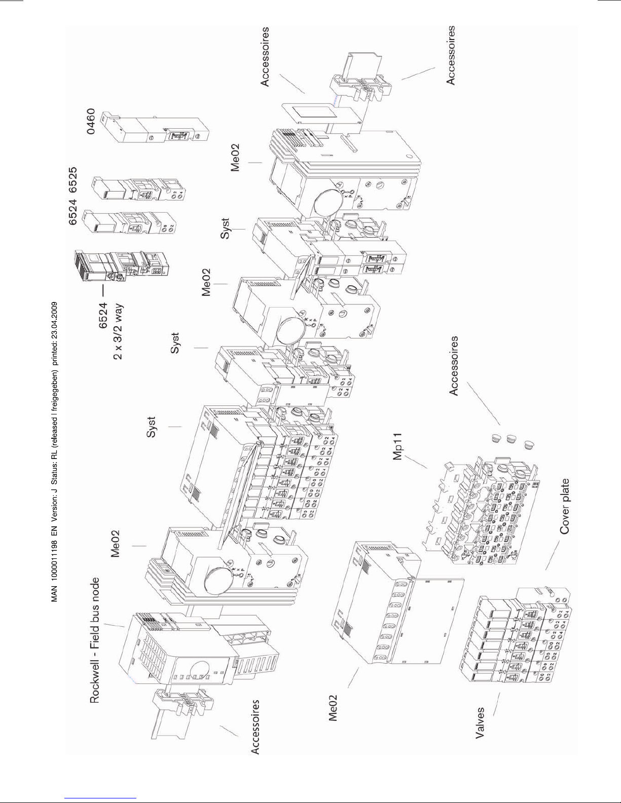
Add-on dimension 11 mm
6527
6526
Accessories
0461
Me03
6525
6524
Syst
Syst
Me03
Syst
Syst
Me03
Rockwell-Field bus node
Me03
Mp12
Valves
Accessories
Cover
Cover plate
Add-on dimension 16,5 mm

C
ONTENTS
List of contents
Type 8644 AirLINE -Rockwell
GENERAL NOTES .................................................................................................................................................................................................................................3
Symbols
General safety notes
Scope of delivery
Warranty conditions
Approvals
Assembly note
Information of the Internet
..................................................................................................................................................................................................................................................... 4
................................................................................................................................................................................................................ 4
........................................................................................................................................................................................................................... 6
.................................................................................................................................................................................................................... 6
................................................................................................................................................................................................................................................. 6
.................................................................................................................................................................................................................................. 6
................................................................................................................................................................................................... 6
INSTALLATION/COMMISSINONING ....................................................................................................................................................................... 7
Installation instructions
Illustration of the Valve block
Removing the valve block from the top-hat rail
Installation of the AirLINE system
Fluidic installation
Labelling of the connections
........................................................................................................................................................................................................... 8
........................................................................................................................................................................................... 8
....................................................................................................................................... 9
........................................................................................................................................................................ 10
...................................................................................................................................................................................................................... 11
........................................................................................................................................................................................ 12
deutsch
Elektrical installation
.............................................................................................................................................................................................................. 13
Fluidic commissioning
Electrical commissioning
MAINTENANCE AND TROUBLESHOOTING ........................................................................................................................................ 15
Troubleshooting
............................................................................................................................................................................................................................ 16
......................................................................................................................................................................................................... 13
................................................................................................................................................................................................. 13
8644/Rockwell - 1
C
ONTENTS
SYSTEM DESCRIPTION ......................................................................................................................................................................................................... 17
Bürkert-AirLINE modulare elektrical / pneumatic automation system
Valve block (variable configuration)
Valve units
Connector modules
Basic electrical module
Basic pneumatic module
Valves
Limitations for use in Zone 2
deutsch
ANNEX ................................................................................................................................................................................................................................................................. A1
.......................................................................................................................................................................................................................................... 23
................................................................................................................................................................................................................. 26
...................................................................................................................................................................................................... 40
.................................................................................................................................................................................................. 51
....................................................................................................................................................................................................................................................... 53
........................................................................................................................................................................................ 55
EC Declaration of Conformity
Certificate of Conformity
................................................................................................................................................................................................. A3
................................................................................................................................................................... 22
................................................................................................................................................................................... A2
................................................................... 19
2 - 8644/Rockwell
General Notes
GENERAL NOTES
SYMBOLS
GENERAL SAFETY NOTES
..........................................................................................................................................................................................................................................................
.............................................................................................................................................................................................
Protection from damage by electrostatic charging
Safety notes for the valve
SCOPE OF DELIVERY
WARRANTY CONDITIONS
APPROVALS
..............................................................................................................................................................................................................................................
ASSEMBLY NOTE
INFORMATION ON THE INTERNET
................................................................................................................................................................................................................ 5
................................................................................................................................................................................................................
.................................................................................................................................................................................................
..............................................................................................................................................................................................................................
.....................................................................................................................................................................
.......................................................................................................................................... 4
4
4
6
6
6
6
6
8644/Rockwell - 3
GENERAL NOTES
SYMBOLS
The following symbols are used in these operating instructions:
marks a work step that you must carry out
ATTENTION!
marks notes on whose non-observance your health or the functioning of the device will
be endangered
NOTE
marks important additional information, tips and recommendations
GENERAL SAFETY NOTES
Please observe the notes in these operating instructions together with the conditions of use and permitted
data that are specified in the data sheet, in order that the device will function perfectly and remain operable for a long time:
• Keep to standard engineering rules in planning the use of and operating the device!
• Installation and maintenance work are only allowed by specialist personnel using suitable tools!
• Observe the current regulations on accident prevention and safety for electrical devices during
operation, maintenance and repair of the device!
• Always switch off the power supply before intervening in the system!
• Note that in systems under pressure, piping and valves may not be loosened!
• T ake suitab le precautions to prev ent inadvertent operation or damage by unauthorized action!
• After interruption of the electrical or pneumatic supply , mak e sure the process is restarted in a welldefined, controlled manner!
• On non-observance of these notes and unauthorized interference with the device, we will refuse all
liability and the warranty on device and accessories will become void!
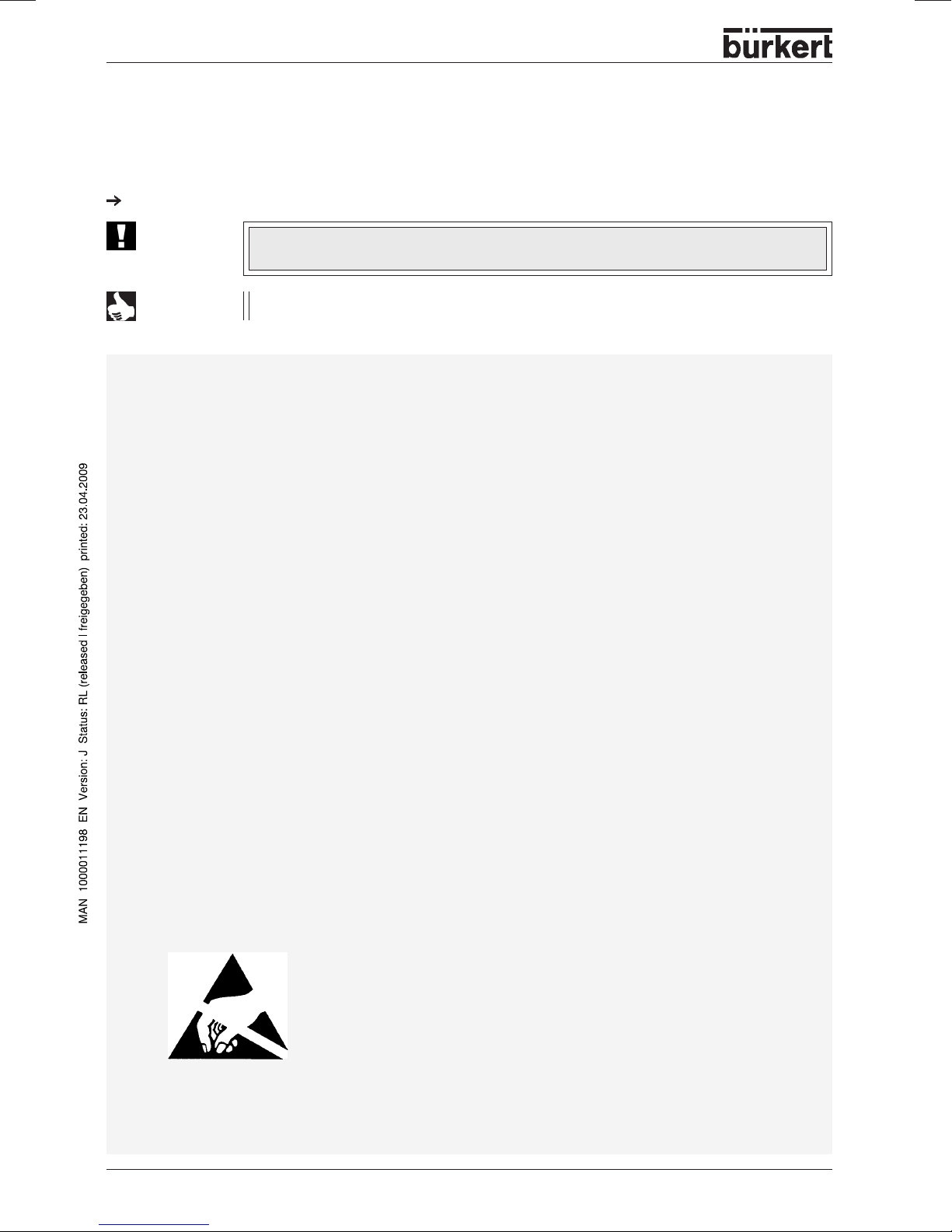
Protection from damage by electrostatic charging
The unit contains electronic components that are very sensitive to
electrostatic discharge (EDS). Contact to electrostatically charged
persons or objects will endanger these components. In the worst case,
they will be immediately destroyed or will fail after commissioning.
Observe the requirements of EN 100 015 - 1 in order to minimize the
possibility of, or avoid, damage from instantaneous electrostatic
discharge. Also take care not to touch components that are under
A TTENTION
EXERCISE CAUTION ON
HANDLING !
ELECTROST ATICALL Y
SENSITIVE COMPONENTS /
MODULES
4 - 8644/Rockwell
supply voltage.
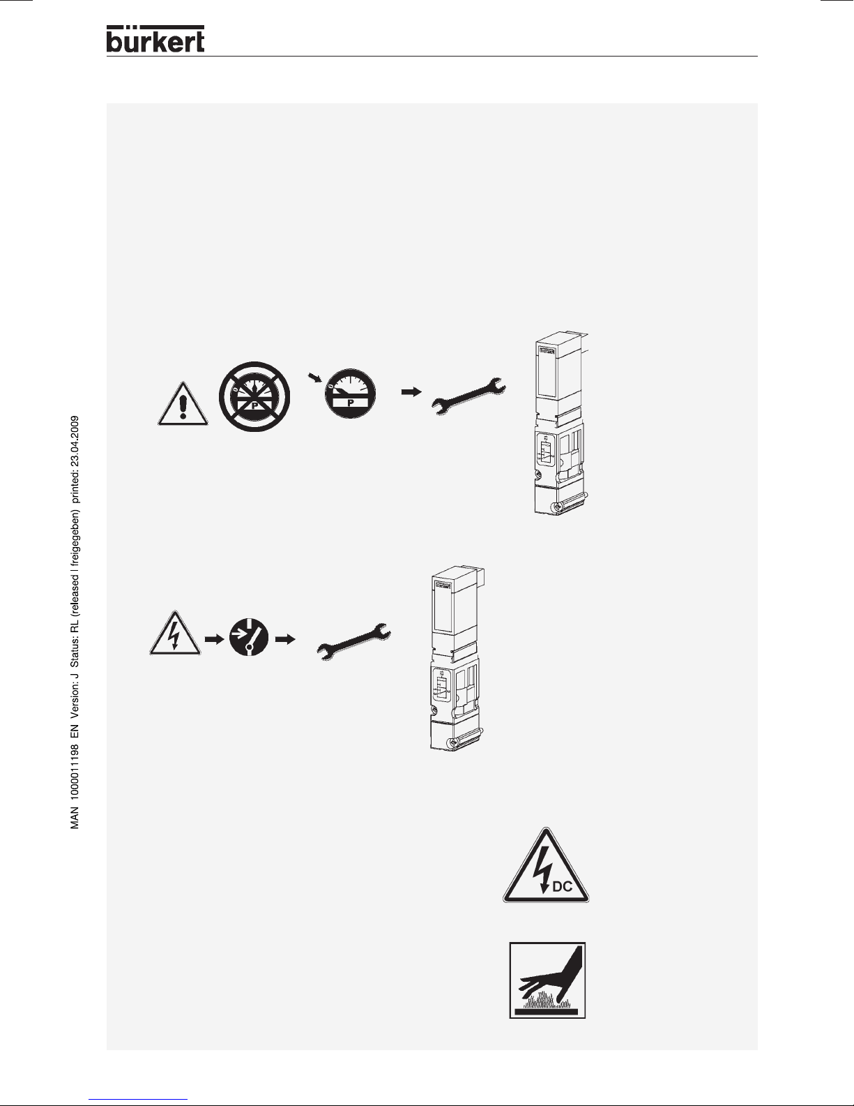
Safety notes for the valve
ATTENTION!
• Keep to standard engineering rules in planning the use of and operating the device!
• T ake suitab le precautions to prevent inadv ertent operation or damage by unauthorized action!
• Note that in systems under pressure, piping and valves may not be loosened!
0 bar, psi, kPa
GENERAL NOTES
• Always switch off the power supply before intervening in the system!
• To avoid pressure drop on s witching, make the v olume of the pressure supply as large as
possible!
• The device shall only be operated on direct current !
•
Risk of injury!
In continuous operation, the coil can become very hot!
8644/Rockwell - 5
GENERAL NOTES
SCOPE OF DELIVERY
Immediately after receipt of the goods, make sure the contents are undamaged and agree with the scope of
delivery stated on the packing slip.
In case of irregularities, contact our customer service department at once:
Bürkert Fluid Control Systems
Service Department
Chr.-Bürkert-Str. 13-17
D-76453 Ingelfingen
T el.: (07940) 10-111
Fax: (07940) 10-448
E-mail: inf o@de.buerkert.com
Or to your Bürkert Sales Center
WARRANTY CONDITIONS
This document contains no warranty statements. In this connection we refer to our general sales and
business conditions. A prerequisite for validity of the warranty is use of the device as intended with
observance of the specified conditions of use.
ATTENTION!
The warranty covers only faultless condition of the automation system and the
attached valves supplied. No liability will be accepted for consequential damage of any
kind that may arise from failure or malfunctioning of the device.
APPROVALS
The approval marks on Bürkert rating plates refer to the Bürkert products. In order that the complete v alv e
island is approved, a gateway with a design inspection certificate must be used. In this case, a valv e
island may be extended with appro v ed units having design inspection certificates up to 64 valv es.
More detailed information on the approvals of the valv es is to be f ound in the chapter V alv es.
ASSEMBLY NOTE
If the configuration of the valve b loc k also pro vides of Type 0461 (5/2- way pulsed v alv e , 5/3- w ay valve), a
profile rail EN 50022-35x15 must be used.
INFORMATION ON THE INTERNET
Operating instructions and data sheets for type 8644 may be found on the Internet under:
www.buerkert.com Germany Produkte Downloads Betriebsanleitungen Typ 8644 Roc kwell
Furthermore , a complete documentation is availab le on CD . The complete Operating instructions may be
ordered under the following indentification number: 804 718
NOTE
6 - 8644/Rockwell
T echnical data, configur ation files and a detailed description of bus terminals and electrical
function terminals by the Rockwell company are available on the Internet web site:
www.ab.com Manuals On-Line I/O 1734 Point I/O
Bürkert has no influence upon the update status of the latter home page or on changes in
technical data or presentation on the pages linked thereto .

INSTALLA TION / COMMISSIONING
Installation / Commissioning
Installation instructions..................................................................................................................... 8
Illustration of the Valve block............................................................................................................. 8
Removing the valve block from the top-hat rail..................................................................................9
Installation of the AirLINE system.................................................................................................... 10
Fluidic installation............................................................................................................................. 11
Labelling of the connections............................................................................................................. 12
Electrical installation ........................................................................................................................ 13
Fluidic commissioning...................................................................................................................... 13
Electrical commissioning ................................................................................................................. 13
8644/Rockwell - 7
INSTALLA TION / COMMISSIONING
Installation instructions
The valve b loc k of the AirLINE-system Type 8644 is combined with the P oint I/O System from the Roc kw ell
company. Please observe the respectiv e installation notes.
ATTENTION!
Before starting installation work, switch off the voltage in the vicinity and secure it
against being switched on again.
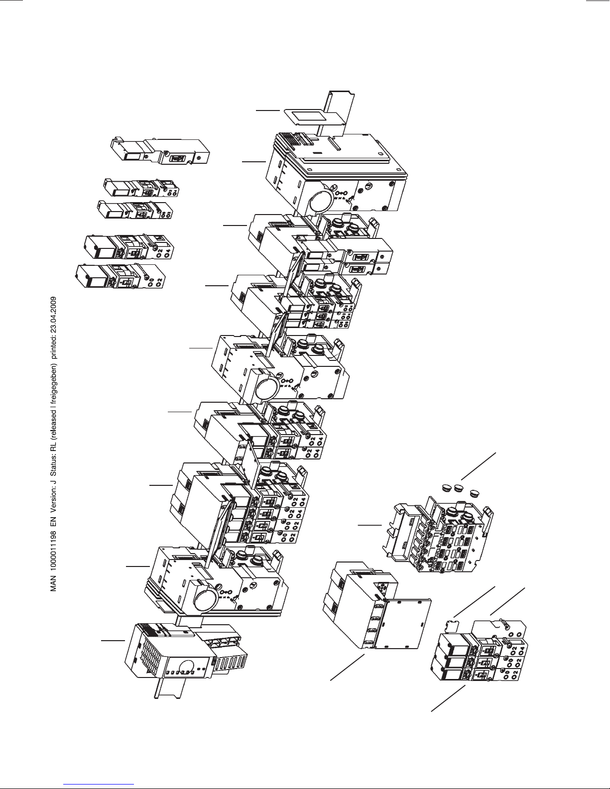
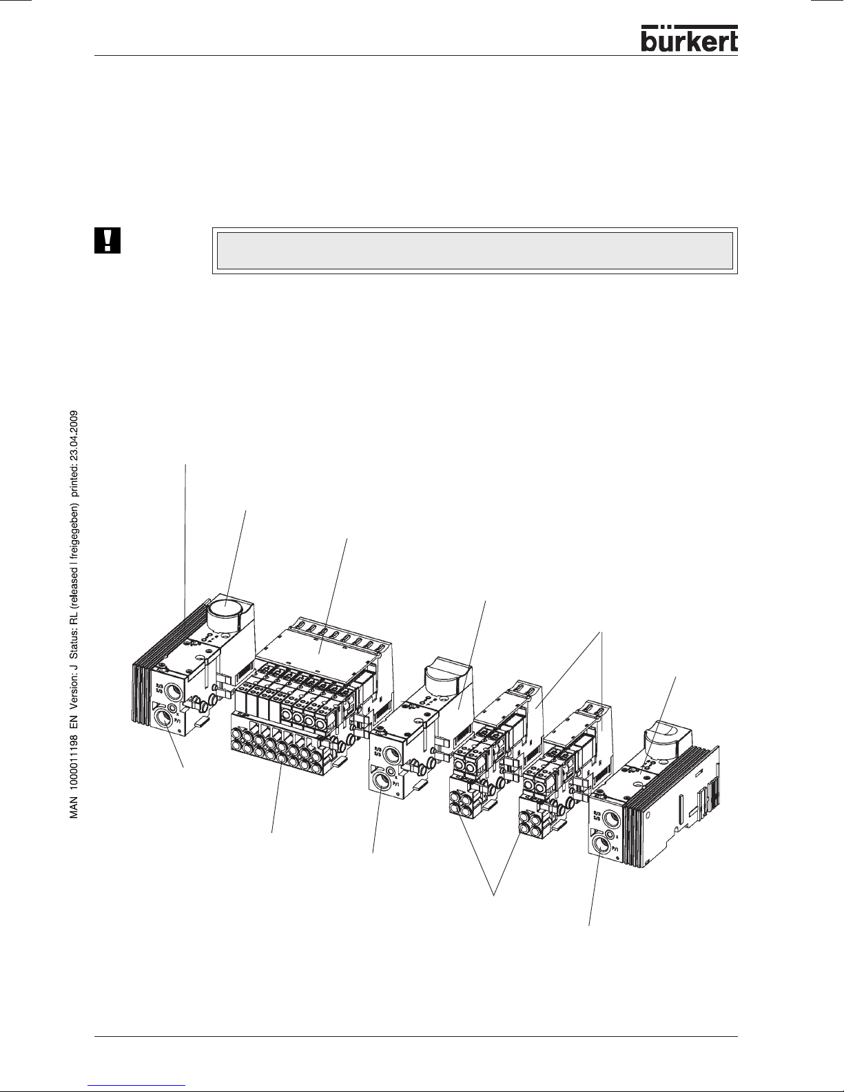
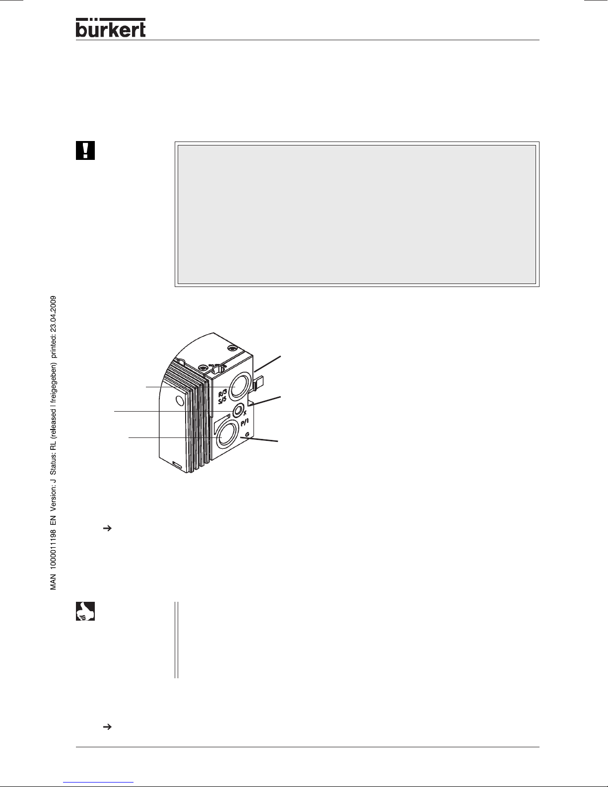
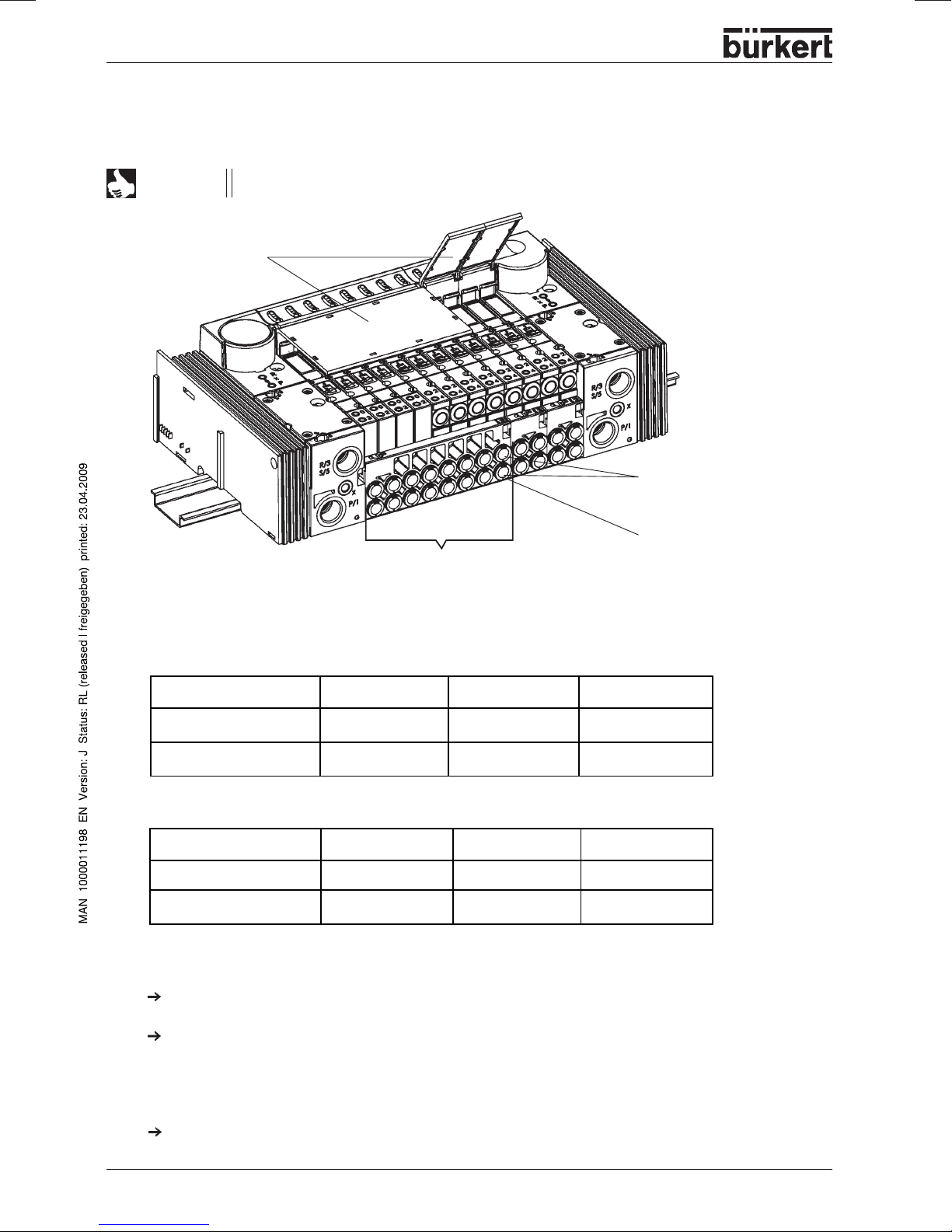
Illustration of the Valve block
Connector
module left
Manometer for indication of operating
pressure at the station
8-fold valve unit
Intermediate supply
2-fold valve units
Supply and exhaust
ports
Service ports
Illustration of the modules
of the Bürkert AirLINE system
Connection
module right
Supply and exhaust ports
Service ports
Supply and exhaust
ports
8 - 8644/Rockwell
INSTALLA TION / COMMISSIONING
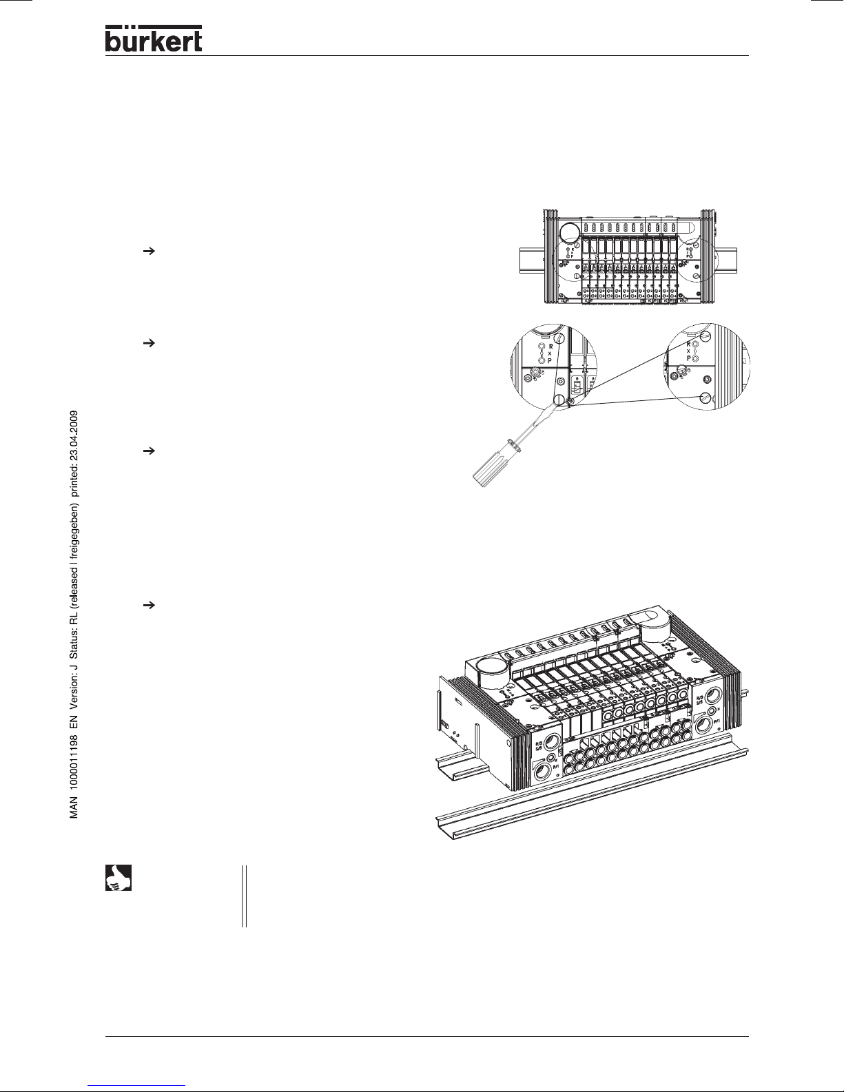
Removing the valve block from the top-hat rail
The valve block is firmly screwed to a standard rail. Additional electrical modules / terminals can be
mounted on this.
If present, release the adjacent modules /
terminals!
Unlock the Vavle bloc k from the standard rail b y
turning the fixing screws anticlockwise as far as
they will go.
Lift the Valve block vertically from the rail.
Disconnect the modules / terminals from the
standard rail following the manuf acturer’s
instructions.
NOTE
The interface of the left-hand connection module contains elements that can be
damaged if force is used.
Never place the valve block on its side, and ensure that you use an approved
installation position!
8644/Rockwell - 9
INSTALLA TION / COMMISSIONING
Installation of the AirLINE system (e.g. in a control cabinet)
ATTENTION!
During work in the control cabinet, observe the relevant safety regulations!
Before mounting, check whether the mounting rail is properly anchored in the control
cabinet or in the system.
Observe the sequence of installation specified in the configuration file(s).
Observe the notes for the connected system!
According to the manufacturer’ s instructions (Chapter 2: Installing the Mounting Base /Wiring Base
Assembly, Installing I/O Modules), snap all electrical modules / terminals onto the standard rail to the
left of the valve block.
Slide the valve block onto the standard rail along the interface of the previous module.
NOTE
Screw the valve block to the rail by tightening the fixing screws clockwise.
Mount all other modules / terminals on the rail.
ATTENTION!
Alternative for large valve blocks:
- Remove the preceding module
- Snap the valve block onto the standard rail
- Slide the block to its final position
- Snap on the preceding module again
The v alv e block is not securely fastened to the standard rail until the fixing screws have
been firmly tightened. Throughout the installation, you m ust ensure that it cannot fall.
10 - 8644/Rockwell
Fluidic installation
Safety notes
INSTALLA TION / COMMISSIONING
ATTENTION!
The pneumatic connections shall not be pressurized during installation!
Make the connections with as large a volume as possible.
Close off unused, open ports with screw caps!
The ports for the pilot valve e xhaust (x) shall not be closed off!
Check allocation according to instructions of ports 1 and 3 or 5: these shall under no
circumstances be swapped!
Pneumatic connections - supply units
Exhaust air
W
(R/S) 3/5
X
W
Standard model: Venting of the pilot valves
Auxiliary air control model: P-port for the pilot valves
(P) 1
W
Pressure supply port
Procedure
Plug (D10) or screw (G 1/4, NPT 1/4) the connections, depending on the version, into the respective
service ports.
Notes on plug connections
NOTE
For the plug connections the hoses must fulfil the following requirements:
• Minimum hardness of 40 Shore D (to DIN 53505 or ISO 868);
• Outside diameter to DIN 73378 (max. permissible deviation ± 0.1 mm from nominal
dimension);
• Free from burrs , cut off at right angles and undamaged over outer circumference;
• The hoses shall be pushed into the plug connectors as far as they will go .
Disassembly of the plug connections
T o release the hoses , depress the pressure ring and pull out the hose.
8644/Rockwell - 11
INSTALLA TION / COMMISSIONING
Pneumatic connections - valve units
NOTE
Labelling area
Variants
With 3/2-way valv es, the upper ports remain free!
Service ports with 5/2way valves
Service ports with 3/2way valves
8-fold valve unit or
4 / 2-fold valve units
5/2-way valves
Variant 1 Variant 2 Variant 3
Service port above (2)
Service part below (4)
M 5 M 7 D 6, D4, D1/4
M 5 M 7 D 6, D4, D1/4
3/2-way valves
Variant 1 Variant 2 Variant 3
Service port above (0)
Service port below (2)
internally closed off internally closed off internally closed off
M 5 M 7 D 6, D4, D1/4
Assembly
Plug (D6, D4, D1/4) or screw (M 5, M7) the connections, depending on the version, into the respective
service ports.
With threaded versions, connecting nipples may be used.
Labelling of the connections
Write the valve port data on the provided Labels
12 - 8644/Rockwell
INSTALLA TION / COMMISSIONING
Elektrical installation
All the necessary steps for this should be taken from the Rockwell Operating Instructions Chapter 2 „Wiring
the Adapter“.
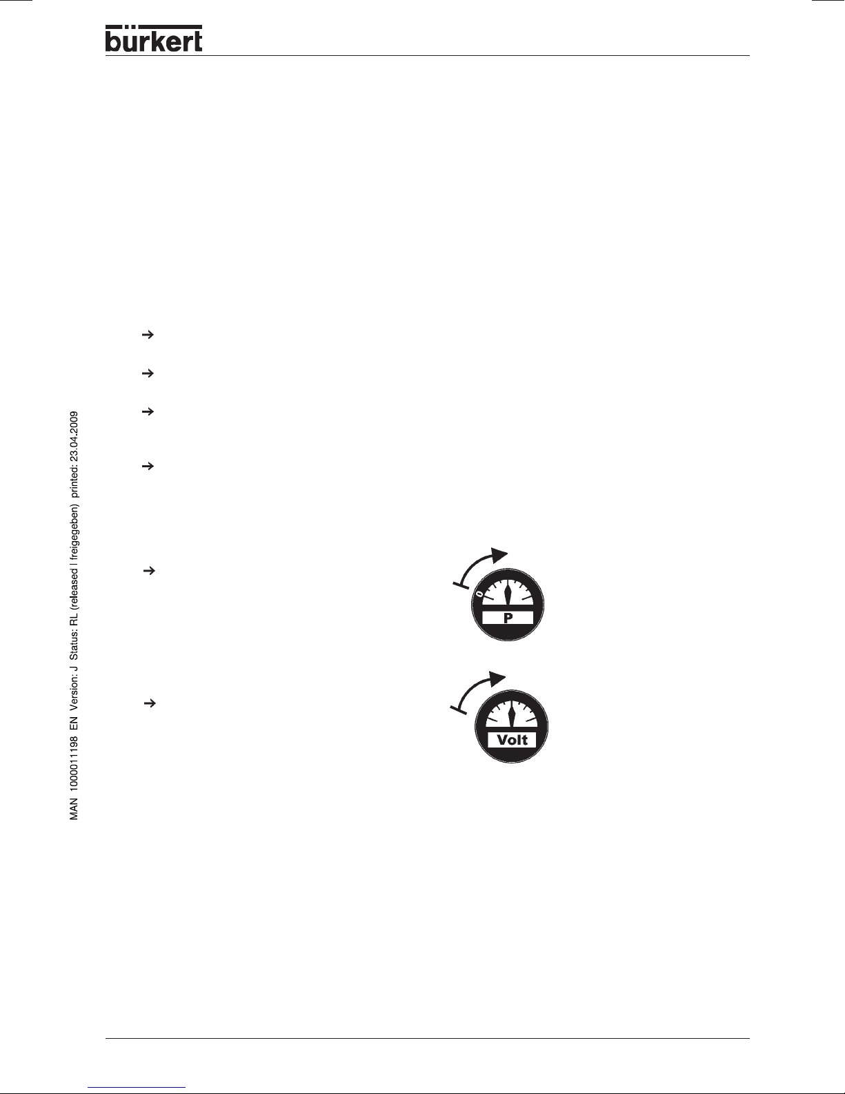
Fluidic commissioning
Measures to be taken before fluidic initialization
Check the connections, voltage and operating pressure!
Make sure that the max. operating data (see rating plate) are not exceeded!
Check allocation according to instructions of ports 1 and 3 or 5: these shall under no circumstances be
swapped!
For electrical operation, unlock the manual override!
Fluidic commissioning
Switch on the pressure supply .
Only then switch on the voltage!
bar
Electrical commissioning
All the necessary steps for this should be taken from the Rockwell Operating Instructions Chapter 3 „How
to Configure Point I/O Modules“.
8644/Rockwell - 13
INSTALLA TION / COMMISSIONING
Special features of commissioning
On delivery , all v alve islands possess a comparable configur ation with regard to module addressing.
The first addressable module after the field bus node has the address 62,
all following modules the address 63.
Reason:
If a passive DeviceNet node (1734-PDN) is used, then automatic addressing can only be performed via the
modules directly. Since it is difficult to remov e the modules o wing to the pneumatic design, the first module
was assigned a different address (62).
NOTE
If an active DeviceNet node is used, automatic addressing must be performed.
With the active Profibus node (1734-APB), this is performed automatically on power-up.
14 - 8644/Rockwell

MAINTENANCE AND TROUBLESHOOTING
Maintenance
and
troubleshooting
TROUBLESHOOTING
.................................................................................................................................................................................................................. 16
8644/Rockwell - 15
MAINTENANCE AND TROUBLESHOOTING
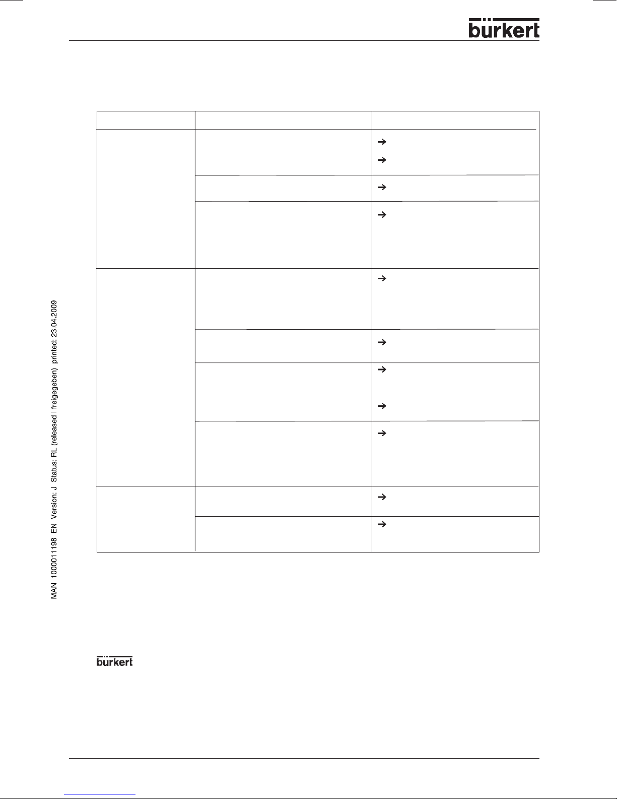
TROUBLESHOOTING
Fault
Valves do not switch:
Valves switch with
delay or blow out at the
vent connections:
Possible cause
Operating voltage not present or insufficient;
Manual override knob not in neutral position;
Pressure supply insufficient or not present.
Pressure supply insufficient or not present;
Valves not in basic position (no power) during
pressure build-up;
Venting of exhaust aire channels insufficient
because silencers are too small or
contaminated (backpressure);
Remedy
Check the electrical connection.
Provide operating voltage acc. to
nameplate.
Turn knob to zero position.
Execute pressure supply with as large a
volume as possible (also for upstream
devices such as pressure controllers,
maintenance units, shut-off valves, etc.).
Minimum operating pressure
Execute pressure supply with as large a
volume as possible (also for upstream
devices such as pressure controllers,
maintenance units, shut-off valves, etc.).
Minimum operating pressure
Pressurize the valve block
valve switch!
Use matching, large-sized silencers or
expansion vessels.
Clean the contaminated silencers.
≥≥
≥
≥≥
before
2,5 bar
≥≥
≥
2,5 bar
≥≥
the
Leaky valve blocks:
Service address:
Service-Department
Chr.-Bürkert-Str. 13-17
D-76453 Ingelfingen
Tel.: (07940) 10-111
Fax: (07940) 10-448
E-mail: info@de.buerkert.com
Fluid Control Systems
Contamination or foreign bodies in pilot or
main valve.
O-rings missing or pinched between the
modules;
missing or wrongly positioned profile seals
between the valve and the basic pneumatic
module.
Change the valve
Determine the point of leakage or missing
seals.
Insert missing seals or replace damaged
seals.
or your Bürkert distribution center (see list of addresses on the last few pages)
16 - 8644/Rockwell
 Loading...