

Page 1
Operating Instructions
Bedienungsanleitung
Instructions de service
Type 8644 AirLINE
with Inline (Phoenix Contact)
mit Inline (Phoenix Contact)
avec Inline (Phoenix Contact)
Page 2

We reserve the right to make technical changes without notice.
T echnische Änderungen vorbehalten.
Sous resérve de modification techniques.
© 2002 Bürkert Werke GmbH & Co. KG
Operating Instructions 0511/11_EU-EN_00804636
Page 3
0460
6525
Accessories
Accessories
Me02
6524
Syst
Me02
Syst
Accessories
Syst
Mp11
Me02
Me02
Accessories
Me02
Cover
Valves
Add-on dimension 11 mm
Cover plate
Page 4
6527
6526
Accessories
Accessories
0461
Me03
6525
6524
Syst
Syst
Me03
Me02
Me03
Syst
Syst
Mp12
Accessories
Cover
Cover plate
Accessories
Me03
Valves
Add-on dimension 16,5 mm
Page 5
C
ONTENTS
List of contents
Type 8644 AirLINE -Phoenix
GENERAL NOTES .................................................................................................................................................................................................................................3
Symbols
Intended use
General safety notes
Scope of delivery
Warranty conditions
Approvals
Assembly note
Information of the Internet
..................................................................................................................................................................................................................................................... 4
......................................................................................................................................................................................................................................... 4
................................................................................................................................................................................................................ 4
........................................................................................................................................................................................................................... 6
.................................................................................................................................................................................................................... 6
................................................................................................................................................................................................................................................. 6
.................................................................................................................................................................................................................................. 6
................................................................................................................................................................................................... 6
INSTALLATION/COMMISSINONING ....................................................................................................................................................................... 7
Installation instructions
Illustration of the Valve block
Removing the valve block from the top-hat rail
Installation of the AirLINE system
........................................................................................................................................................................................................... 8
........................................................................................................................................................................................... 8
....................................................................................................................................... 9
........................................................................................................................................................................ 10
deutsch
Fluidic installation
Labelling of the connections
Elektrical installation
Fluidic commissioning
Electrical commissioning
...................................................................................................................................................................................................................... 11
........................................................................................................................................................................................ 12
.............................................................................................................................................................................................................. 13
......................................................................................................................................................................................................... 13
................................................................................................................................................................................................. 13
MAINTENANCE AND TROUBLESHOOTING ........................................................................................................................................ 15
Troubleshooting
............................................................................................................................................................................................................................ 16
8644/phoenix - 1
Page 6

C
ONTENTS
SYSTEM DESCRIPTION ......................................................................................................................................................................................................... 18
Bürkert-AirLINE modulare elektrical / pneumatic automation system
Valve block
Field bus node Profibus DP
Field bus node Profibus DPV1
Connector modules
Electronic pressure measurement module (PMM)
Basic electronic modules
Basic pneumatic module
Valves
......................................................................................................................................................................................................................................... 22
......................................................................................................................................................................................... 26
................................................................................................................................................................................. 42
................................................................................................................................................................................................................. 90
...................................................................................................................... 104
............................................................................................................................................................................................. 111
............................................................................................................................................................................................... 119
.................................................................................................................................................................................................................................................... 121
................................................................... 19
deutsch
ANNEX ................................................................................................................................................................................................................................................................. A1
EC Declaration of Conformity
Certificate of Conformity
................................................................................................................................................................................... A2
................................................................................................................................................................................................. A3
2 - 8644/phoenix
Page 7

General Notes
GENERAL NOTES
SYMBOLS
INTENDED USE
GENERAL SAFETY NOTES
..........................................................................................................................................................................................................................................................
....................................................................................................................................................................................................................................
.............................................................................................................................................................................................
Protection from damage by electrostatic charging
Safety notes for the valve
SCOPE OF DELIVERY
WARRANTY CONDITIONS
APPROVALS
..............................................................................................................................................................................................................................................
ASSEMBLY NOTE
................................................................................................................................................................................................................ 5
................................................................................................................................................................................................................
.................................................................................................................................................................................................
..............................................................................................................................................................................................................................
.......................................................................................................................................... 5
4
4
4
6
6
6
6
INFORMATION ON THE INTERNET
.....................................................................................................................................................................
8644/phoenix - 3
6
Page 8
GENERAL NOTES
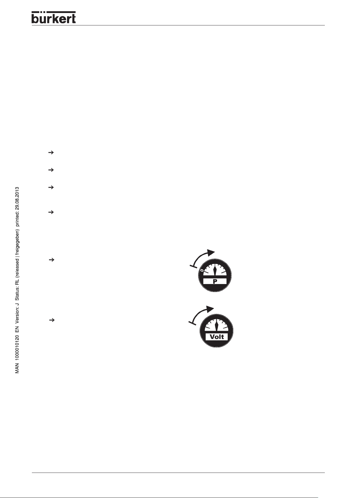
SYMBOLS
The following symbols are used in these operating instructions:
marks a work step that you must carry out
ATTENTION!
NOTE
marks notes on whose non-observance your health or the functioning of the device will be
endangered.
marks important additional information, tips and recommendations
INTENDED USE
The device is used exclusively as an electrical/pneumatic automation system in conjunction with Phoenix
electronics modules. It is designed for use in the switching cabinet or control box. The de vice must only be
operated using the values indicated in the "Technical data f or the ov erall system" and "Technical data for
the valve block" sections and on the type plates.
Read the instructions for use carefully. In particular, follow the chapter "Gener al safety inf ormation". The
operating manual describes the entire life cycle of the device. Retain the operating instructions so that they
are accessible for the respectiv e user.
The safety features of the device may not be circumvented under any circumstances. It is imperative to
comply with all accident prevention stipulations . The components mounted on commissioning must not be
disassembled without express, written working instructions.
The system must only be installed and maintained by trained specialist personnel.
Unauthorized rebuilding or changes within the system are not allowed for saf ety reasons. When e xchanging
parts due to failure or normal wear, use only original replacement parts.
Attention must be paid to the working instructions in the individual sections. The saf ety inf ormation must be
complied with at all times. Should working instructions, their sequence, safety information or the safety
label not be complied with, the claim for liability shall lapse.
GENERAL SAFETY NOTES
• Keep to standard engineering rules in planning the use of and operating the device!
• Installation and maintenance work are only allowed by specialist personnel using suitable tools!
• Observe the current regulations on accident prevention and safety for electrical devices during
operation, maintenance and repair of the device!
• Always switch off the power supply before intervening in the system!
• Note that in systems under pressure, piping and valves may not be loosened!
• T ake suitab le precautions to prevent inadv ertent operation or damage by unauthorized action!
• After interruption of the electrical or pneumatic supply , make sure the process is restarted in a welldefined, controlled manner!
• On non-observance of these notes and unauthorized interference with the device, we will refuse all
liability and the warranty on device and accessories will become void!
4 - 8644/phoenix
Page 9
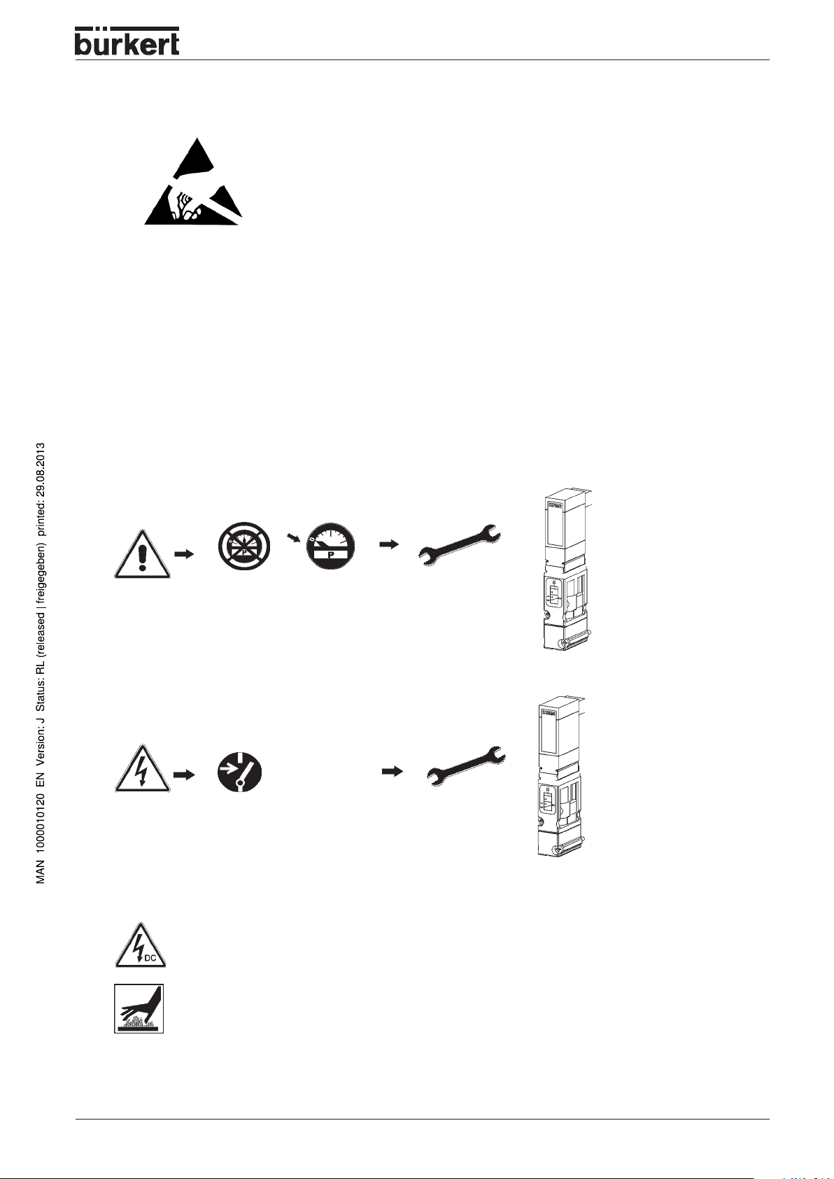
Protection from damage by electrostatic charging
The unit contains electronic components that are very sensitive to
electrostatic discharge (EDS). Contact to electrostatically charged
persons or objects will endanger these components. In the worst case,
they will be immediately destroyed or will fail after commissioning.
GENERAL NOTES
A TTENTION
EXERCISE CAUTION ON
HANDLING !
ELECTROST ATICALLY
SENSITIVE COMPONENTS /
MODULES!
Observe the requirements of EN 100 015 - 1 in order to minimize the
possibility of, or avoid, damage from instantaneous electrostatic
discharge. Also take care not to touch components that are under
supply voltage.
Safety notes for the valve
• Keep to standard engineering rules in planning the use of and operating the device!
• T ak e suitable precautions to prev ent inadvertent operation or damage by unauthorized action!
• Note that in systems under pressure, piping and valves may not be loosened!
0 bar, psi, kPa
• Always switch off the power supply before intervening in the system !
• To avoid pressure drop on switching, make the v olume of the pressure supply as large as possible!
• The device shall only be operated on direct current!
• Risk of injury!
In continuous operation, the coil can become very hot!
8644/phoenix - 5
Page 10
GENERAL NOTES
SCOPE OF DELIVERY
Immediately after receipt of the goods, make sure the contents are undamaged and agree with the scope of
delivery stated on the packing slip.
In case of any discrepancies, please contact our Call Center
Bürkert Fluid Control Systems
Call-Center
Chr.-Bürkert-Str . 13-17
D-76453 Ingelfingen
T el.: (07940) 10-111
Fax: (07940) 10-448
E-mail: inf o@de.bue rkert.com
or your local Bürkert Sales Center immediately .
WARRANTY CONDITIONS
This document contains no warranty statements. In this connection we refer to our general sales and
business conditions. A prerequisite for validity of the warranty is use of the device as intended with
observance of the specified conditions of use.
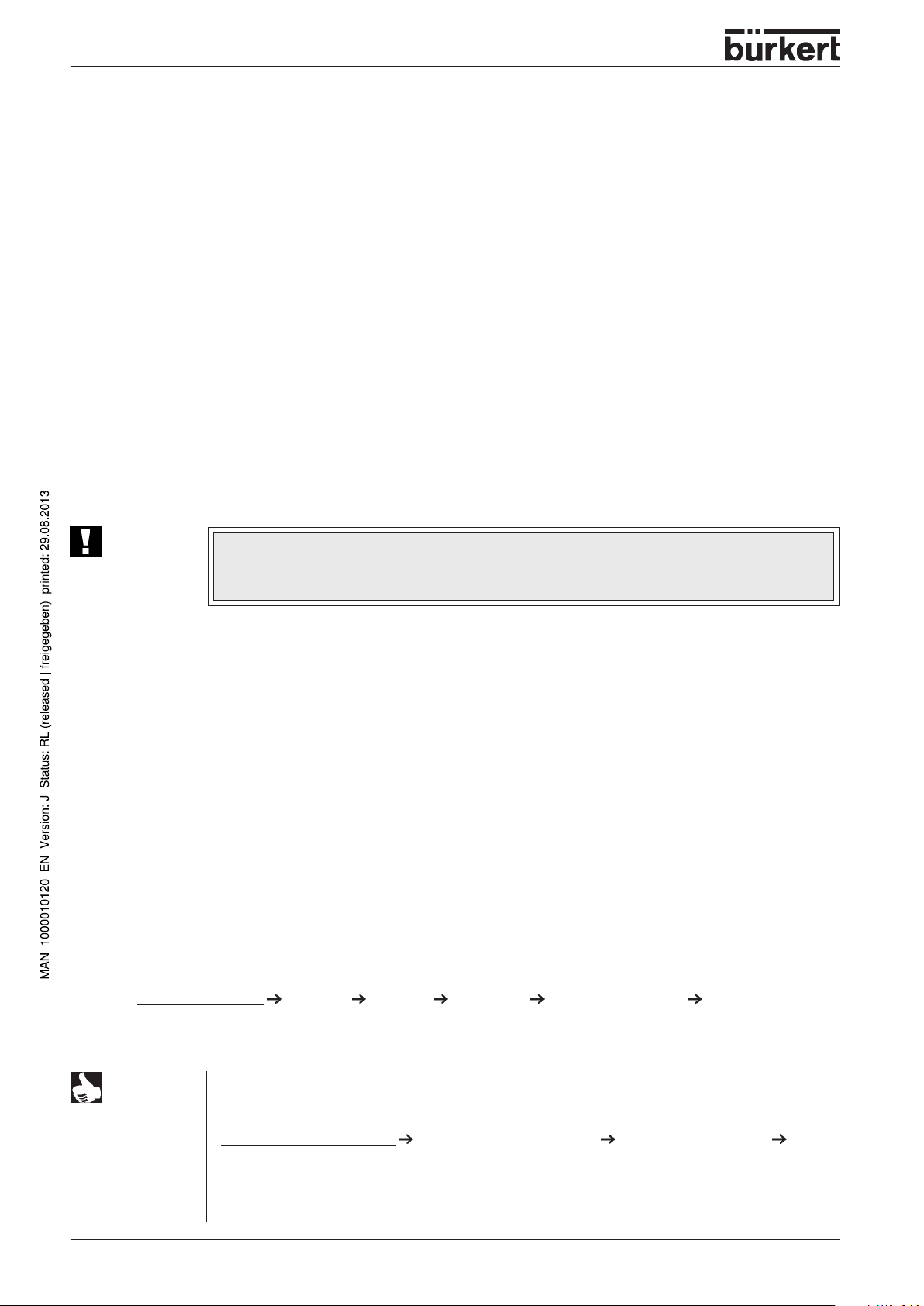
ATTENTION!
The warranty covers only faultless condition of the automation system and the attached
valves supplied. No liability will be accepted for consequential damage of any kind that
may arise from failure or malfunctioning of the device.
APPROVALS
The approval marks on Bürkert rating plates refer to the Bürkert products. In order that the complete v alv e
island is approved, a gateway with a design inspection certificate must be used. In this case, a valv e
island may be extended with appro v ed units ha ving design inspection certificates up to 64 valves .
More detailed information on the approvals of the v alves is to be found in the chapter Valves.
ASSEMBLY NOTE
If the configuration of the valve block also provides of Type 0461 (5/2- way pulsed valv e , 5/3- way valve), a
profile rail EN 50022-35x15 must be used.
INFORMATION ON THE INTERNET
Operating instructions and data sheets for type 8644 may be found on the Internet under:
www.buerkert.com Germany Produkte Downloads Betriebsanleitungen Typ 8644 Phoenix
Furthermore, a complete documentation is available on CD . The complete Operating instructions ma y be
ordered under the following indentification number: 804 636
HINWEIS
6 - 8644/phoenix
T echnical data, configur ation files and a detailed description of bus terminals and electrical
function terminals by the Phoenix Contact company are available on the Internet web site:
www.phoenixcontact.com Download & Documetation Interbus & A utomation
Documentation
Then enter in the search window e.g. "IL" as joker or the exact product designation.
Bürkert has no influence upon the update status of the latter home page or on changes in
technical data or presentation on the pages linked thereto.
Page 11

INSTALLATION / COMMISSIONING
Installation / Commissioning
Installation instructions..................................................................................................................... 8
Illustration of the Valve block............................................................................................................. 8
Removing the valve block from the top-hat rail..................................................................................9
Installation of the AirLINE system.................................................................................................... 10
Fluidic installation............................................................................................................................. 11
Labelling of the connections............................................................................................................. 12
Electrical installation ........................................................................................................................ 13
Fluidic commissioning...................................................................................................................... 13
Electrical commissioning ................................................................................................................. 13
8644/phoenix - 7
Page 12
INSTALLATION / COMMISSIONING
Installation instructions
The AirLINE system Type 8644 may be combined with the electrical automation systems of various
manufacturers. You should follow the respective installation instructions .
ATTENTION!
Before starting installation work, switch off the voltage in the vicinity and secure it
against being switched on again.
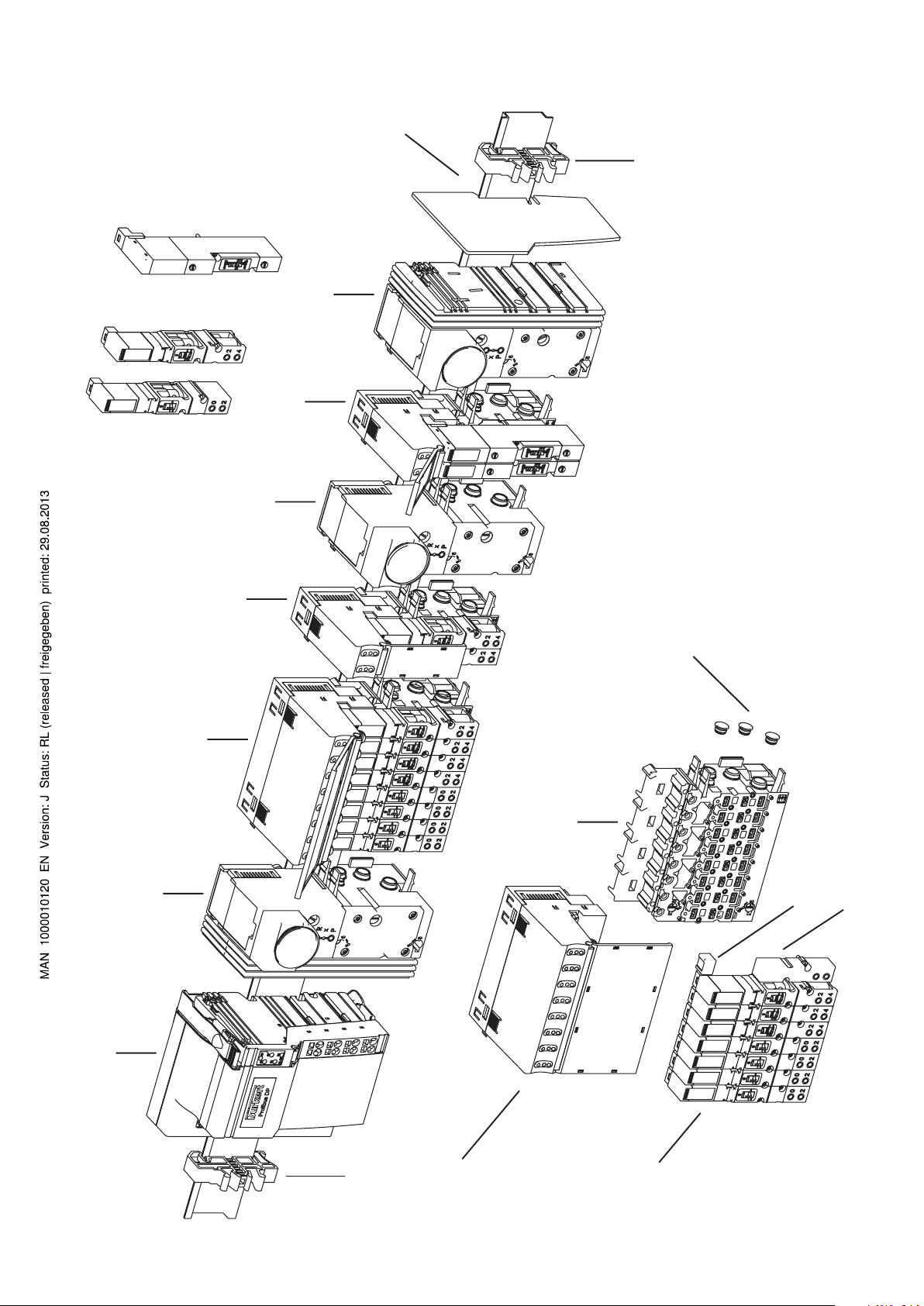
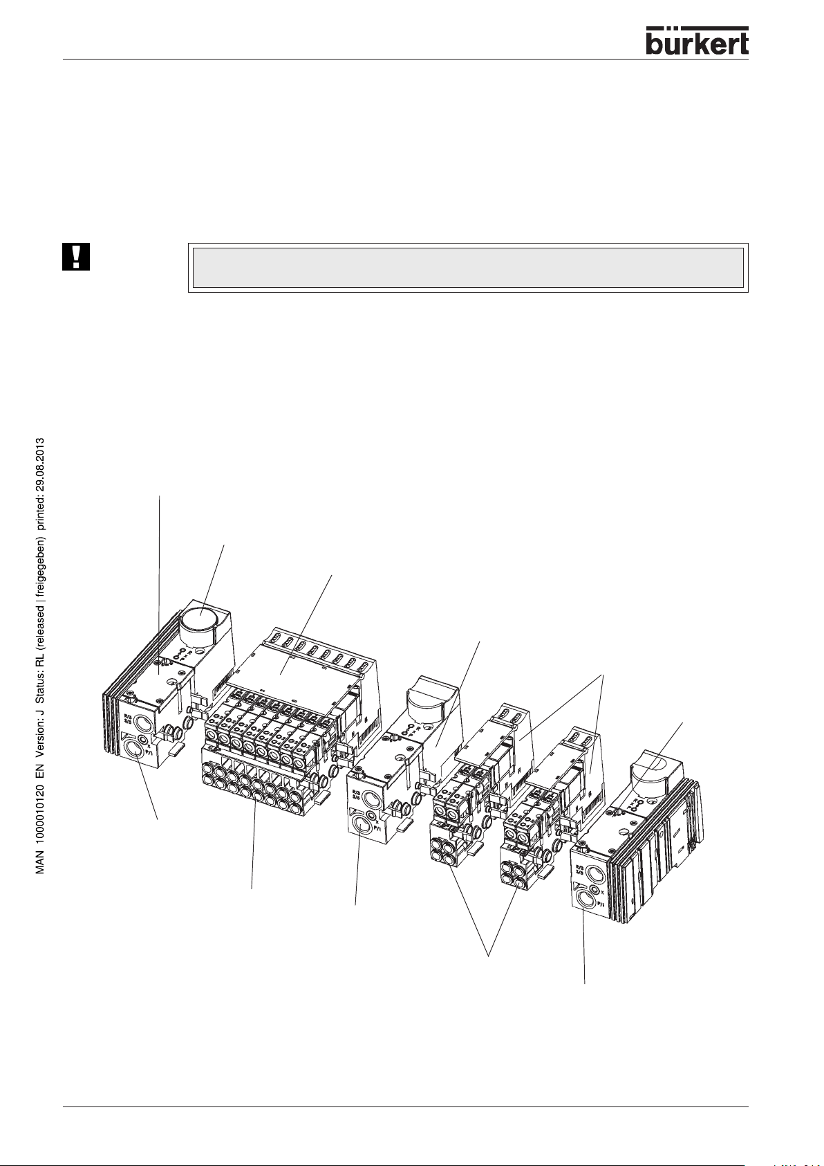
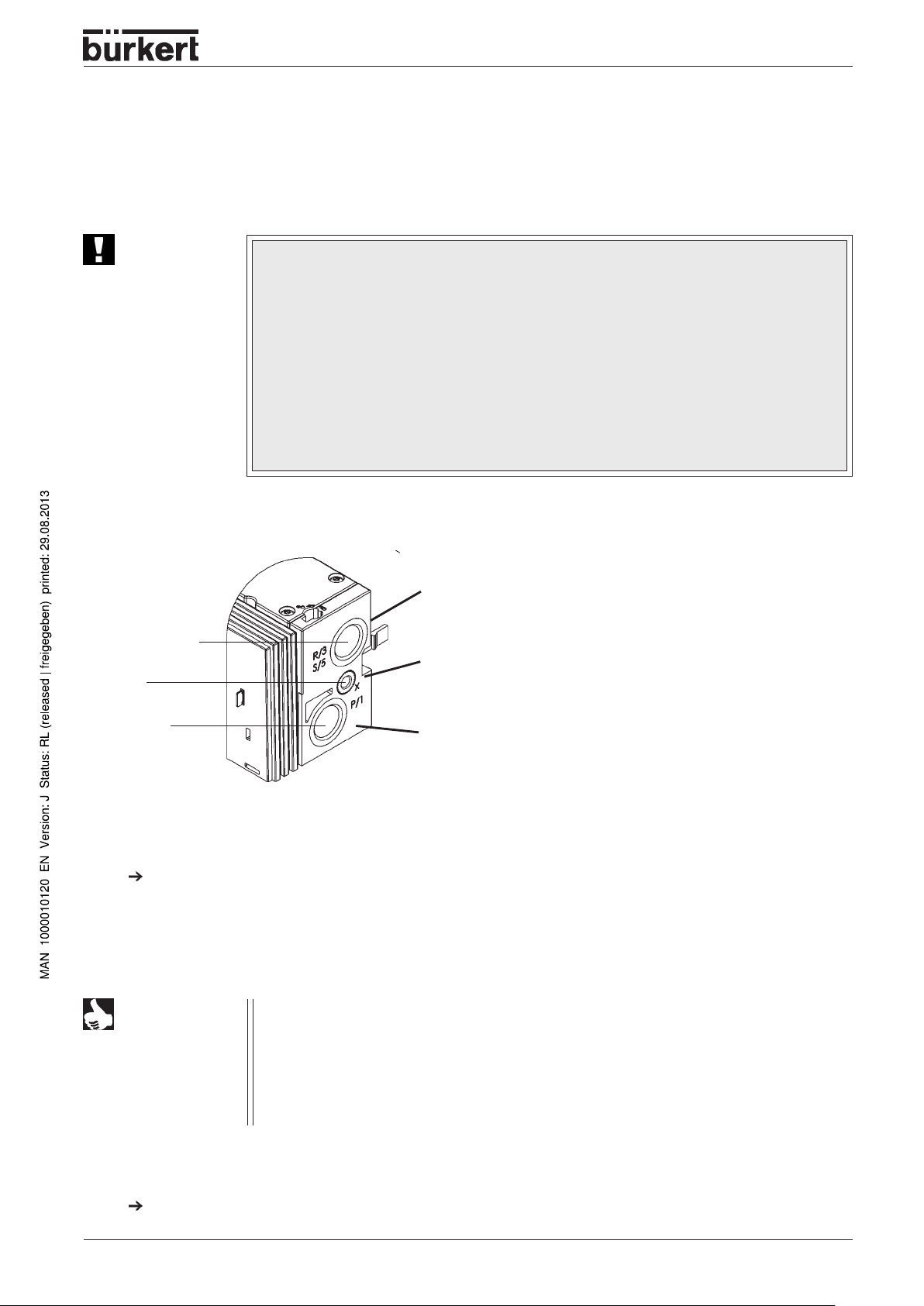
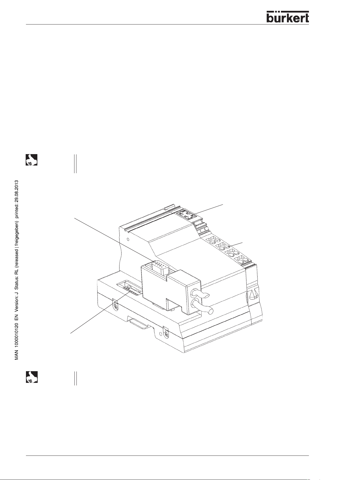
Illustration of the Valve block
Connector
module left
Manometer for indication of operating
pressure at the station
8-fold valve unit
Intermediate supply
Supply and exhaust
ports
Service ports
Illustration of the modules
of the Bürkert AirLINE system
2-fold valve units
Connection
module right
Supply and exhaust ports
Service ports
Supply and exhaust
ports
8 - 8644/phoenix
Page 13
INSTALLATION / COMMISSIONING
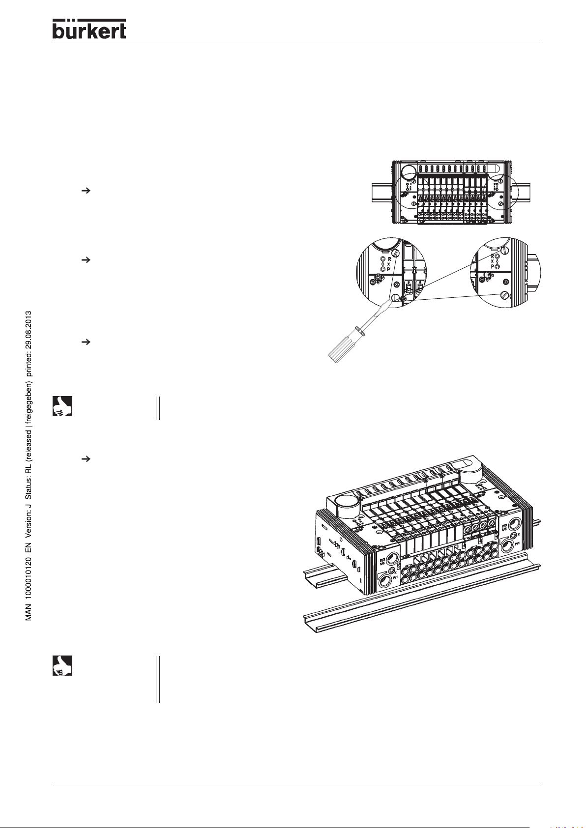
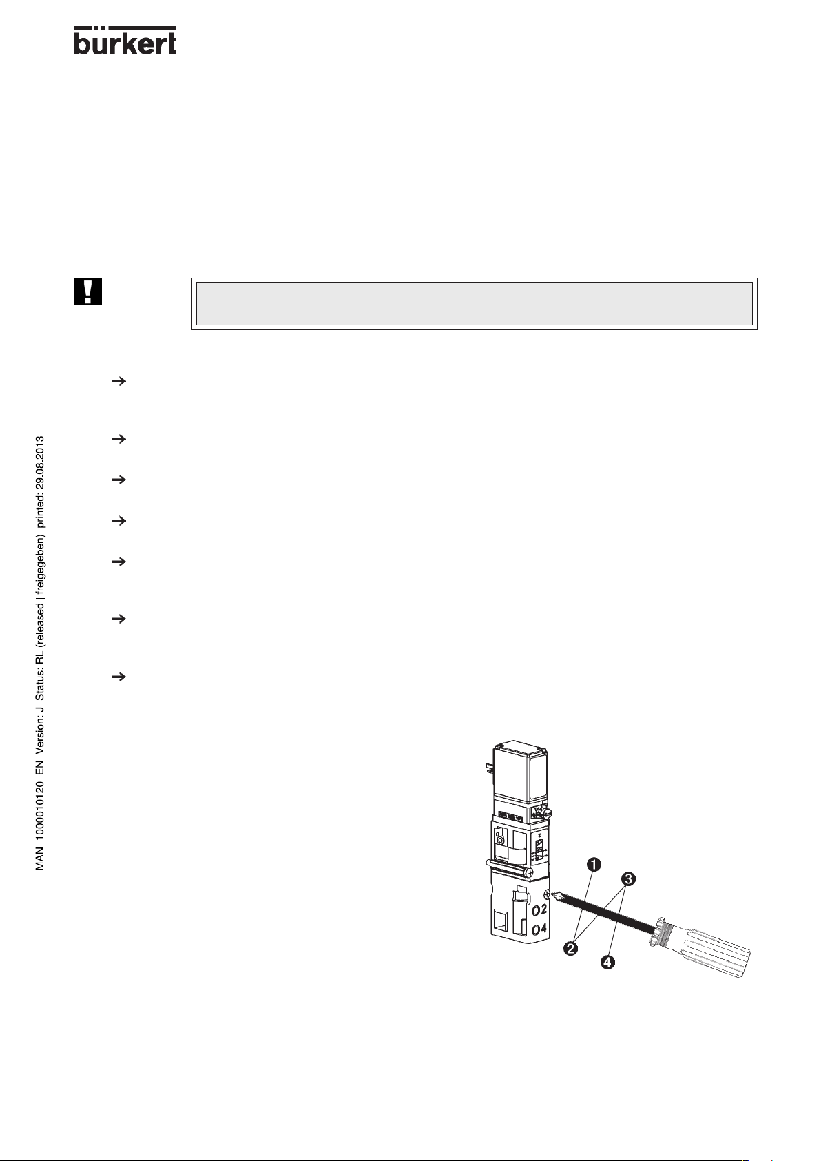
Removing the valve block from the top-hat rail
The valve block is firmly screwed to a standard rail. Additional electrical modules / terminals can be
mounted on this.
If present, release the adjacent modules /
terminals!
Unlock the Vavle block from the standard rail by
turning the fixing screws anticlockwise as far as
they will go.
Lift the Valve block vertically from the rail.
NOTE
Disconnect the modules / terminals from the
standard rail following the manuf acturer’s
instructions.
There must be sufficient clearance > 6 mm between Valve block and previous module.
NOTE
The interface of the left-hand connection module contains elements that can be
damaged if force is used.
Never place the valve block on its side, and ensure that you use an approved
installation position!
8644/phoenix - 9
Page 14
INSTALLATION / COMMISSIONING
Installation of the AirLINE system (e.g. in a control cabinet)
ATTENTION!
During work in the control cabinet, observe the relevant safety regulations!
Before mounting, check whether the mounting rail is properly anchored in the control
cabinet or in the system.
Observe the sequence of installation specified in the configuration file(s).
Observe the notes for the connected system!
Observing manufacturer’s instructions, snap all electrical modules / terminals to the left of the valve
block onto the standard rail.
Slide the valve block onto the rail along the interface of the preceding module.
NOTE
Screw the valve block to the rail by tightening the fixing screws clockwise.
Mount all other modules / terminals on the rail.
ATTENTION!
Alternative for large valve blocks:
- Remove the preceding module
- Snap the valve block onto the standard rail
- Slide the block to its final position
- Snap on the preceding module again
The v alve block is not securely fastened to the standard rail until the fixing screws have
been firmly tightened. Throughout the installation, you m ust ensure that it cannot fall.
10 - 8644/phoenix
Page 15
Fluidic installation
Safety notes
INSTALLATION / COMMISSIONING
ATTENTION!
The pneumatic connections shall not be pressurized during installation!
Make the connections with as large a volume as possible.
Close off unused, open ports with screw caps!
The ports for the pilot valve e xhaust (x) shall not be closed off!
Check allocation according to instructions of ports 1 and 3 or 5: these shall under no
circumstances be swapped!
Pneumatic connections - supply units
Exhaust air
W
(R/S) 3/5
X
W
Standard model: V enting of the pilot valves
Auxiliary air control model: P-port for the pilot valves
(P) 1
W
Pressure supply port
Procedure
Plug (D10) or screw (G 1/4, NPT 1/4) the connections, depending on the version, into the respective
service ports.
Notes on plug connections
NOTE
For the plug connections the hoses must fulfil the following requirements:
• Minimum hardness of 40 Shore D (to DIN 53505 or ISO 868);
• Outside diameter to DIN 73378 (max. permissible deviation ± 0.1 mm from nominal
dimension);
• Free from burrs, cut off at right angles and undamaged ov er outer circumference;
• The hoses shall be pushed into the plug connectors as far as they will go .
Disassembly of the plug connections
T o release the hoses , depress the pressure ring and pull out the hose.
8644/phoenix - 11
Page 16
INSTALLATION / COMMISSIONING
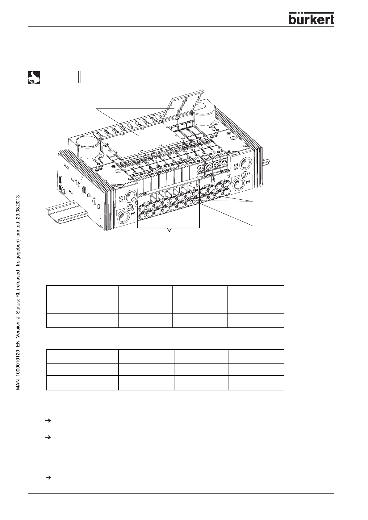
Pneumatic connections - valve units
NOTE
With 3/2-way valv es, the upper ports remain free!
Labelling area
Service ports with 5/2way valves
Service ports with 3/2way valves
8-fold valve unit or
4 / 2-fold valve units
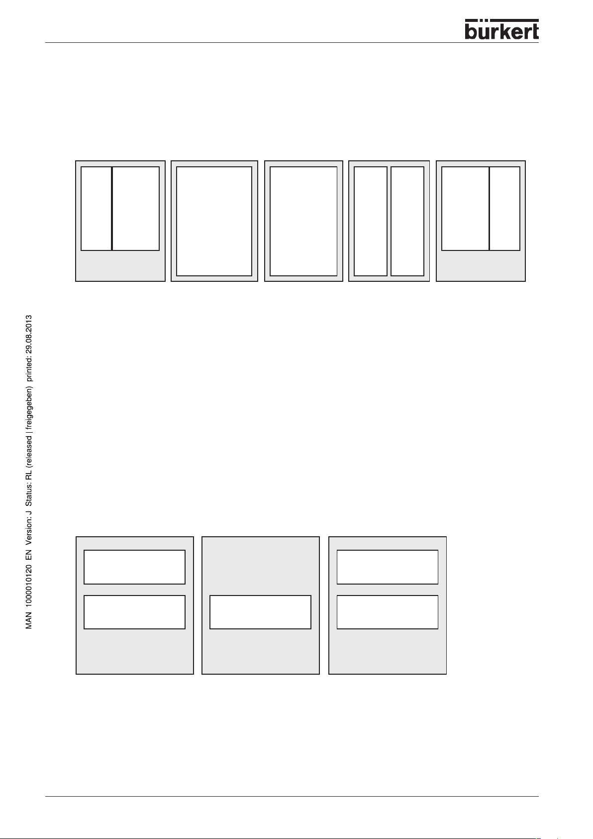
Variants
5/2-way valves
Variant 1 Variant 2 Variant 3
Service port above (2)
Service part below (4)
M 5 M 7 D 6, D4, D1/4
M 5 M 7 D 6, D4, D1/4
3/2-way valves
Variant 1 Variant 2 Variant 3
Service port above (0)
Service port below (2)
internally closed off internally closed off internally closed off
M 5 M 7 D 6, D4, D1/4
Assembly
Plug (D6, D4, D1/4) or screw (M 5, M7) the connections, depending on the version, into the respective
service ports.
With threaded versions, connecting nipples may be used.
Labelling of the connections
Write the valve port data on the provided Labels.
12 - 8644/phoenix
Page 17
INSTALLATION / COMMISSIONING
Elektrical installation
You can find information regarding the electrical installation:
- in the Phoenix Contact handbook
- or in the
System Description
Interbus - Inline IB IL SYS PRO UM
chapter, P aragraph
Field Bus Nodes Profibus DP
Fluidic commissioning
Measures to be taken before fluidic initialization
Check the connections, voltage and operating pressure!
Make sure that the max. operating data (see rating plate) are not exceeded!
Check allocation according to instructions of ports 1 and 3 or 5: these shall under no circumstances be
swapped!
For electrical operation, unlock the manual override!
Fluidic commissioning
Switch on the pressure supply .
Only then switch on the voltage!
Electrical commissioning
bar
You can find information regarding the electrical initialization:
- in the Phoenix Contact handbook
- or in the
System Description
Interbus - Inline IB IL SYS PRO UM
chapter, P aragraph
Field Bus Nodes Profibus DP
8644/phoenix - 13
Page 18

INSTALLATION / COMMISSIONING
14 - 8644/phoenix
Page 19

MAINTENANCE AND TROUBLESHOOTING
Maintenance
and
troubleshooting
TROUBLESHOOTING
.................................................................................................................................................................................................................. 16
8644/phoenix - 15
Page 20
MAINTENANCE AND TROUBLESHOOTING
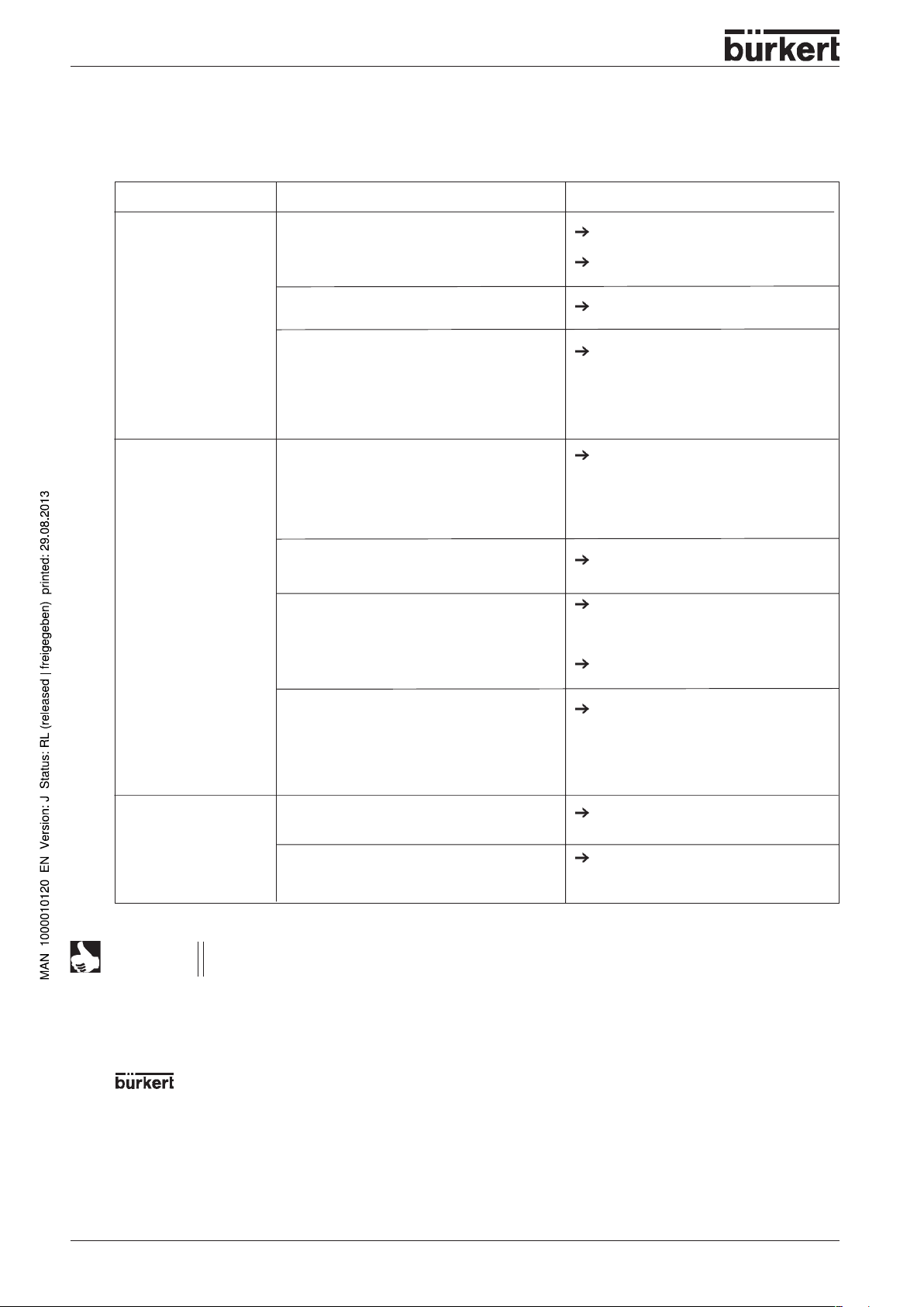
TROUBLESHOOTING
Fault
Valves do not switch:
Valves switch with
delay or blow out at the
vent connections:
Possible cause
Operating voltage not present or insufficient;
Manual override knob not in neutral position;
Pressure supply insufficient or not present.
Pressure supply insufficient or not present;
Valves not in basic position (no power) during
pressure build-up;
Venting of exhaust aire channels insufficient
because silencers are too small or
contaminated (backpressure);
Remedy
Check the electrical connection.
Provide operating voltage acc. to
nameplate.
Turn knob to zero position.
Execute pressure supply with as large a
volume as possible (also for upstream
devices such as pressure controllers,
maintenance units, shut-off valves, etc.).
Minimum operating pressure
Execute pressure supply with as large a
volume as possible (also for upstream
devices such as pressure controllers,
maintenance units, shut-off valves, etc.).
Minimum operating pressure
Pressurize the valve block
valve switch!
Use matching, large-sized silencers or
expansion vessels.
≥≥
≥
≥≥
before
2,5 bar
≥≥
≥
2,5 bar
≥≥
the
Leaky valve blocks:
NOTES
The further error descriptions, see User´s Manual
chapter
System Descriptions,
Service address:
Service-Department
Chr.-Bürkert-Str. 13-17
D-76453 Ingelfingen
Tel.: (07940) 10-111
Fax: (07940) 10-448
E-mail: info@de.buerkert.com
Fluid Control Systems
Contamination or foreign bodies in pilot or
main valve.
O-rings missing or pinched between the
modules;
missing or wrongly positioned profile seals
between the valve and the basic pneumatic
module.
section
Field Bus Nodes Profibus DP
Clean the contaminated silencers.
Change the valve
Determine the point of leakage or missing
seals.
Insert missing seals or replace damaged
seals.
Interbus - Inline IB IL SYS PRO UM
.
or the
or your Bürkert distribution center (see list of addresses on the last few pages)
16 - 8644/phoenix
Page 21

SYSTEM DESCRIPTION
System description
BÜRKERT AIRLINE MODULAR ELECTRICAL / PNEUMATIC
AUTOMATION SYSTEM.................................................................................................... 19
Features ........................................................................................................................................... 19
Advantage ........................................................................................................................................ 19
Design of the system ....................................................................................................................... 20
VALVE BLOCK
Connector modules / feeders........................................................................................................... 22
Valve units
Technical data for the valve block.................................................................................................... 24
Technical data for the complete system ..........................................................................................25
............................................................................................................................................................................................................................................................ 23
.......................................................................................................................................................................................................................................
22
FIELD BUS NODE PROFIBUS DP...................................................................................26
Description of the Profibus DP field bus node ................................................................................. 26
Technical data of the field bus module Profibus DP bus node......................................................... 31
Installation and electrical commissioning of the field bus node Profibus DP
Electrical installation of the field bus node Profibus DP................................................................... 35
Configuration of the Profibus DP bus node...................................................................................... 37
Diagnosis and error elimination at the Profibus DB bus nodev ....................................................... 40
.................................................................. 33
FIELD BUS NODE PROFIBUS DPV1 .............................................................................. 42
New functions .................................................................................................................................. 42
Overview of firmware functionalities................................................................................................ 43
Description of field bus node............................................................................................................ 44
PCP via process data (PCP in DPV0) ............................................................................................ 54
Parameterization .............................................................................................................................. 62
Failsafe values ................................................................................................................................. 65
Watchdog ......................................................................................................................................... 68
Acknowledgement of peripheral errors ............................................................................................70
Behaviour in PLC stop (new) ........................................................................................................... 71
8644/phoenix - 17
Page 22
SYSTEM DESCRIPTION
Diagnosis (new) ............................................................................................................................... 72
Parameter telegram f ormat............................................................................................................... 76
Switching round bytes for IB IL24 DI16 / IB IL24 DO16 .................................................................. 78
Switching round bytes for IB IL24 DI32 / IB IL24 DO32 .................................................................. 78
Data Exchange and Global Command Operate .............................................................................. 79
DPV1 field bus node object directory .............................................................................................. 80
Error codes during DPV1 communication ....................................................................................... 82
Error codes during PCP communication ......................................................................................... 83
Error description .............................................................................................................................. 85
CONNECTOR MODULES ................................................................................................. 90
Connector Module, pneumatic - left Type ME02 .............................................................................. 92
Connector Module, pneumatic - left Type ME03 .............................................................................. 94
Connector Module, pneumatic - middle Type ME02......................................................................... 96
Connector Module, pneumatic - middle Type ME03......................................................................... 98
Connector Module, pneumatic - right T ype ME02 .......................................................................... 100
Connector Module, pneumatic - right Type ME03
........................................................................................................................................... 102
ELECTRONIC PRESSURE MEASUREMENT MODULE (DMM) .................................. 104
BASIC ELECTRONIC MODULES .................................................................................. 111
Basic electronic module ME02 / 2-fold monostable ....................................................................... 112
Basic electronic module ME02 / 8-fold monostable ....................................................................... 113
Basic electronic module ME02 / 2-fold bistable
Basic electronic module ME03 / 2-fold monostable ....................................................................... 115
Basic electronic module ME03 / 4-fold monostable ....................................................................... 116
................................................................................................................................................ 114
Basic electronic module ME03 / 3-fold 10 mm monostable ........................................................... 117
Basic electronic module ME03 / 2-fold bistable
................................................................................................................................................ 118
BASIC PNEUMATIC MODULE .......................................................................................119
Basic pneumatic module with integral pressure shut-off ............................................................... 120
VALVES...........................................................................................................................121
18 - 8644/phoenix
Page 23

SYSTEM DESCRIPTION
MODULAR ELECTIRCAL / PENUMATIC AUTOMATION SYSTEM TYPE
8644 AirLINE
AirLINE Type 8644 is an electrical and pneumatic automation system which has been developed for use in
control cabinets or boxes. In a through system, all electronic and pneumatic components are standardized
so that if simple rules are complied with, electrical and electronic modules of differing functionality may be
combined in a very simple manner. All components are connected via a snap-on mechanism. This includes
the necessary electrical connections. In this way, for example, valv es and po wer outputs may be combined
with only one field bus connection. A number of electrical modules (terminals) may be combined very
simply with valves mounted on special pneumatic modules (valve units).
Features
Characteristics of AirLINE are:
• Simple handling
• Functional block construction of switched box or cabinet.
• Automatic build-up of potential groups, current, data and safety circuits.
• Combination of valve units and terminals in differing cluster size (2-fold, 4-fols, ...) for space and price
optimized station construction.
Advantages
This principle brings the following advantages:
• Flow-optimized valve structure
Pressure range from vacuum to 10 bar
Flow rates of approx. 300l/min or 700 l/min with a valve width of 10 mm and/or 16 mm.
• Integration of non-return valves into the pneumatic base module (optional).
• High service life through rocker technology with oiled and non-oiled air .
• Simple combination of different functions, configuration and e xtension through high lev el of modularity .
• Numerous valve functions: 3/2, 5/2 (monostable, bistable) and 5/3 way functions.
• Mechanical Manual-Emergency operation.
• Different pressure levels possible in a single chain.
• Integration of pressure gauges for display of the operational pressure.
• Central compressed air supply via connection modules possible on both sides, as well as intermediate
supply.
8644/phoenix - 19
Page 24
SYSTEM DESCRIPTION
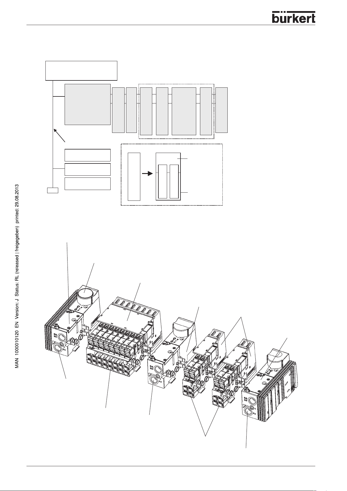
Design of the system
Central control
(e.G. SPC)
Field bus node 1
(e.G. Profibus DP))
Valve block
DO DI AI
2x 4x 2x 2x
Field bus
Field bus node 2
Field bus node …
Field bus node n
2x
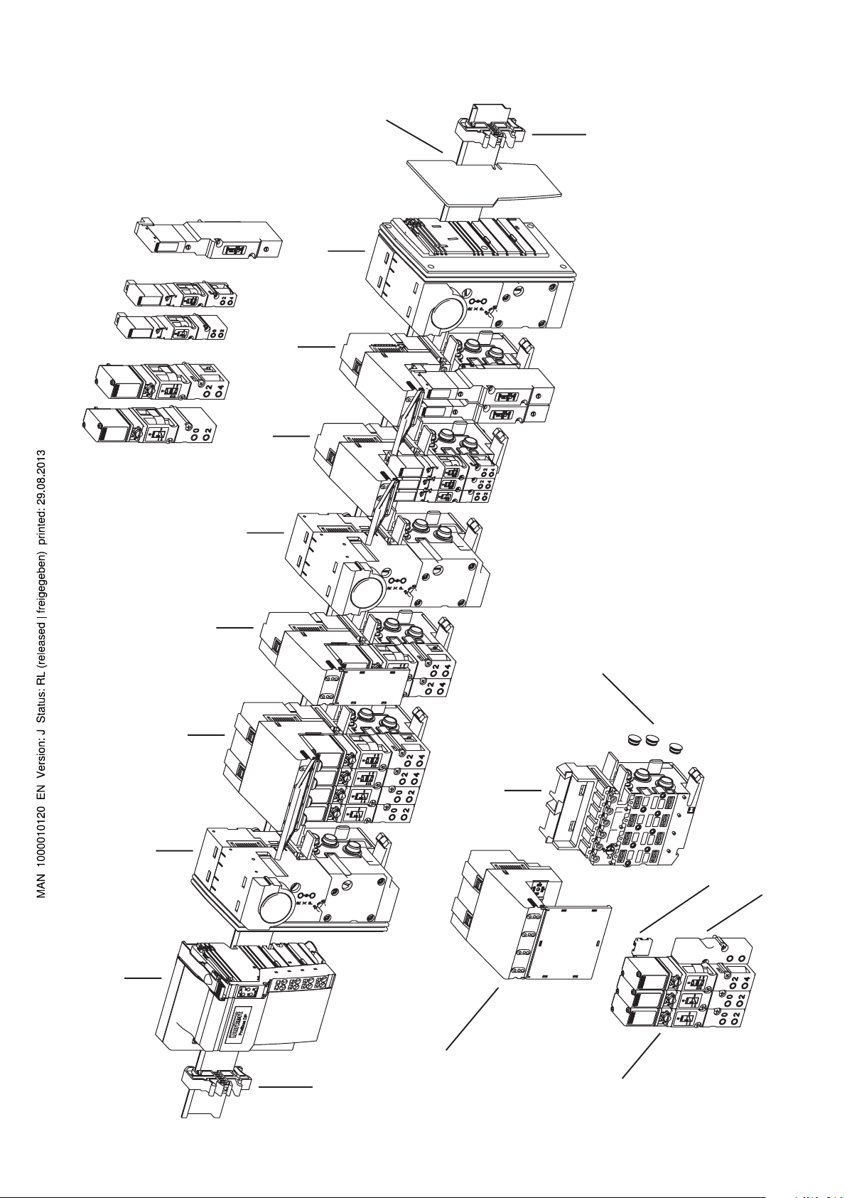
llustration of the valve block
Connector module left
Manometer for indication of
operating pressure at the station
8-fold valve unit
Connection module
Valve plate
Valve plate
Valve
Valve plate
8x
Electronic base
module
Valve
Pneumatic base
module
Connection module
Schematic representation of
the Bürkert AirLine system
Supply and exhaust
ports
Service ports
Illustration of the modules of
the Bürkert AirLine system
Intermediate supply
2-fold valve unit
Connector module
right
Supply and exhaust ports
Service ports
Supply and exhaust
ports
20 - 8644/phoenix
Page 25
SYSTEM DESCRIPTION
System description
In its minimal configuration, the system consists of field bus nodes and the Valve block.
The closing plate protects both the system and persons from improper contact.
T erminals can be arranged bef ore and after the valve b lock
Procedure for changing the electrical function module:
ACHTUNG!
Do not introduce foreign parts into the basic module (24V supply bus)-
-> Risk of short circuit
Switch off the electricity and compressed air supplies to the AirLINE
system
Unscrew fixing screws of the valves with a screwdriver
Pull valve off valve plug
Keep dirt awa y from flange seal and O-ring (3/2 valve)
Loosen the functional module at the rear latching mechanism and pull
away upwards from the distributor module (backplane bus) without tilting it.
Set the new functional module vertically on the distributor module (backplane bus) and press downwards until it can be heard to latch in.
Place valve with clean inserted flange seals/O-rings onto the valve position
and tighten the screws according to the adjacent assembly drawing.
20 Ncm
20 Ncm
30 Ncm
30 Ncm
8644/phoenix - 21
Page 26
SYSTEM DESCRIPTION
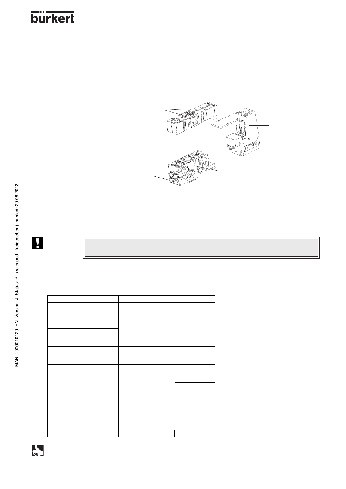
VALVE BLOCK
The valve block is composed of the following modules:
•
Connector modules/supply units
•
V alve units
(service ports , miscellaneous vales)
(collective ports for supply, exhaust and auxiliary control air)
interface
Electrical
Connector
module left
Example of a valve block, schematic
Viewed from the outside, the pneumatic automation system represents a closed electrical unit. Owing to
the modular construction, the number of internal bus participants and the current consumption of the valve
block may v ary. The valv e bloc k and each electrical module/terminal provide a standardized electrical
interface to the outside.
left
Supply units
8-fold valve
units
Intermediate
supply
2-fold valve units
2-fold valve units
Connector
module right
Supply unit
Connector modules / feeders
Feeders in the form of pneumatic connector modules form the fluidic interface between the supply line and
the internal supply structure. The fluid is passed on via the f eeder from one valve unit to the next. In order
that the supply pressure remains almost constant over the entire path, additional feeders may be
necessary . It is recommend to insert a feeder after 24 (ME02) or 16 (ME03) valve positions. The use of
intermediate feeders also enables segments to be built up when the pneumatic channels are closed
between individual valve units.
right
interface
Electrical
Electr . connector
module
Pneumatic
supply module
Connector
module left
22 - 8644/phoenix
Electrical
1:1 shunting
Pneumatic
supply module
Intermediate
supply
Electr. connector module
Pneumatic
supply module
Connector
module right
Schematic
representation of supply
Page 27
VALVE UNITS
Construction
V alve units are of modular construction and consist of:
• Basic electronic modules
• Basic pneumatic modules
• Valves
Valves
SYSTEM DESCRIPTION
Basic electronic
module
Service ports
(outputs)
Modular construction of the valve units
Basic pneumatic module
The digital outputs, on which the valves sit, are switched on the basic electronic module. Depending ont he
function, these switch the internal P channel to the service ports (outputs) of the pneumatic module .
ATTENTION!
Plugged-on valves may only be changed if the pressure in the AirLINE is relieved. If a
pressure shut-off is used, the valves may also be exchanged under pressure.
Variants
The modular construction of the valve units permits of serveral variants.
Types: pneumatic / electronic
Add-on dimens ion
Valve types
No. of valve positions on
basic electronic module
No. of valve positions on
basic pneumatic module
Connection t yp e
(on basic pneumatic module)
Non-return valve (optional)
Pressure shut-off (otional)
MP11/ ME02 MP12 / ME03
11 mm 16,5 mm
6524
6525
0460
2fold
---8fold
2fold
8fold
D6
D4
D1/4"
M5
M7
Without non-return valve
Non-return valve in R channel
Non-return valve in R+S channel
With pressure shut-off*** not available
6526
6527
0461
2fold
3fold*
4fold
2fold
3fold*
4fold
D8
G1/8"
NPT 1/8"
D4
D1/4
D6**
M5**
M7**
*
Width of basic electron/pneumatic module
= 33 mm, with 3 plug-on positions for 10
mm valves 6524 / 6525
**
Special version 3-fold, 10 mm valves
***
Available only for certain valve types and
with functional limitation.
See also the technical data of the valve
block and the description of the basic
pneumatic module.
NOTE
You can obtain information about the correct assembly of modules, valves and accessories
via our Configurator . If y ou hav e any questions, please consult our Distribution Center .
8644/phoenix - 23
Page 28
SYSTEM DESCRIPTION
Technical data of the valve block
(using electronic modules and valve types 6524, 6525, 6526, 6527, 0460, 0461)
Mounting dimension
V alve operation
Flow
Pressure range
(with pressure shut-off) 5 - 7 bar - - -
Po wer
Current
power reduction)
(before / after 43/26 mA 38/ - mA 42/33 mA / 96/48 mA 38/ - mA
Valve places (max.)
Electrical module
Pneumatic module
Protection Class in
(in terminal model)
Ambient temperature
Storage temperature
Nominal operating
11 mm 16.5mm
C/D (3/2-way) L/N (5/3-way) C/D (3/2-way) L/N (5/3-way)
T ype 6524 T ype 0460 Type 6526 T ype 0461
H (5/2-way) H (5/2-pulsed) H (5/2-way) H (5/2-pulsed)
T ype 6525 T ype 0460 Type 6527 T ype 0461
300 l/min 200 l/min 700 l/min 500 l/min
2,5 - 7 bar 2,5 - 7 bar 2 - 10 bar 2,5 - 7 bar
1 Watt 2 x 1 W att 1 Watt / 2 Watt 2 x 1 Watt
64 32 32 24
2; 8 2 bistable 2; 4; 3* 2 bistable
2; 8 2 bistable 2; 4; 3* 2 bistable
IP 20 IP 20 IP 20 IP 20
0 to +55°C 0 to +50°C 0 to +55°C 0 to +50°C
-20 to +60°C -20 to +60°C -20 to +60°C -20 to +60°C
Continuous operation (100 % ED)
mode
Operating voltage
Protection Class
T otal current
24 V / DC; -15 +20 % tolerance**; residual ripple at field bus interf ace 5 %
3 according to VDE 0580
Dependent on the connection technology , the expansion stage and the control
Interface (Profibus)
Profibus Copper conductor (RS-485), connected via Profibus
connector; Po wer supply potentialseparated; screen
electrically connected to the functional earth
Recommended cable lengths see Profibus system data
Local bus
No. of connectable AirLINE terminals
Limited by software max. 64
Limited by power supply unit max. logic current consumption of connected local bus
ATTENTION!
module: I
Observe current consumption of the modules!
On project planning of an AirLINE station, observe the current consumption of the logic of
each participant! This is given in each module-specific data sheet. It may differ from
module to module. Hence the number of possible participants that can be connected
depends on the specific construction of the station.
≤ 2 A DC
max
*3 x 10 mm valves for add-on dimension 16.5 mm
** in the case of the EEx n version, maximum +10 %
24 - 8644/phoenix
Page 29
Technical data for the complete system
Voltage supply:
Rated voltage 24 V/DC
Tolerance - 15% / + 20%
V alve types 0460, 0461 - 10% / + 10%
Current carrying capacity:
Contacts max. 8 A
Valv e block max. 2.5 A
(via connector module left)
Maximum current consumption:
Logic current I_Log = I_Log_FBKN + Σ I_Modul
SYSTEM DESCRIPTION
I_Log Current consumption logic range
I_Log_FBKN proportional current in field bus nodes max. 1.25 A/DC
(0.75 A/DC for logic supply; 0.5 A/DC for analog voltage supply)
I_Module proportional current logic range of the elec. base module max. 15 mA
I_V alve Valv e current - before and after po wer reduction
Valve type
6524
6525
6526
6527
0460
0461
before power reduction after power reduction
43 mA 26 mA
43 mA 26 mA
96 mA 48 mA
96 mA 48 mA
38 mA 38 mA
Valve current
Temperature:
Storage temperature - 20 to + 60 °C
NOTE
Field bus nodes Profibus DP (standard) 0 to + 55 °C
V alve type 6524, 6525, 6526, 6527 0 to + 55 °C
V alv e type 0460, 0461 0 to + 50 °C
The admissible ambient temperature is depent on the modules used. During
assembly, the crucial factor is the most critical module.
8644/phoenix - 25
Page 30
SYSTEM DESCRIPTION
FIELD BUS NODE PROFIBUS DP
Description of the field bus node Profibus DP / technical data
The bus terminal couples an AirLINE station to the Profibus and provides the supply voltages for the
connected participants.
Features:
- Profibus connection using copper technology
- Data rate: all defined transmission rates up to 12 MBd
- Error diagnosis through LEDs on the bus terminals
- Galvanic isolation of the field bus
NOTE
9-pole SUB-D Profibus connector
Profibus DP / DPV1 field bus node
The field bus node has expanded functions in DPV1 mode from serial number 37344
onwards.
Display / LEDs
Supply terminal
DIP switch for
addressing
NOTE
The cover plate is included with the bus terminal. Use this plate to terminate the AirLINE station. The cover
plate has no electrical function. It protects the station from ESD pulses and the user from touching
dangerous voltages.
26 - 8644/phoenix
The Profibus plug is not included in the delivery . Please order the plug according to the
ordering data in the data sheet.
Page 31

SYSTEM DESCRIPTION
Special features with DIP switch 8
As is not the case for the PROFIBUS bus terminal up to serial number 37343 (GSD file: BUER00F0.gsd,
device entry: „Typ8644“), for new devices from serial number 37344 onw ards DIP switch 8 will no longer be
used for setting the stop behaviour , b ut for diff erentiating between DPV0 and DPV1 mode.
For new devices, stop behaviour is set via the parameter telegram:
DIP switch 8 - Position OFF (default setting)
The device is exchange-compatible with the predecessor up to serial number 37343 and provides the
following new functions:
• acyclical communication with e.g. RS232 modules, including in the process data channel
• various diagnosis formats
• acknowledgement of peripheral errors from the application program
• adaptation of the high-byte/low byte format to the control format on 16 and 32-channel input and output
modules.
These functions are, howe ver , only availab le on new devices from serial number 37344 onw ards.
When scheduling projects for the device, use the „BUER00F0.gsd“ GSD or the device entry „8644-
DPV1(DIP8=OFF) ME02“ in the S7 hardware configurator.
DIP switch 8 - Position ON
The device provides all new functions in the ON position.
Stop behaviour, which w as set via DIP s witch 8 in the old de vice , is now adjusted via parameterization.
When scheduling projects for the device, use the „BUER06BA.gsd“ GSD or the device entry „8644-
DPV1(DIP8=ON) ME02“ in the S7 hardware configurator.
8644/phoenix - 27
Page 32

SYSTEM DESCRIPTION
POWER LOSS
Formula for calculation of the power loss of the electronics
PEL = P
PEL = 2,6 W + (1,1 x
Bus
+ P
Peri
W
A
ab
Σ Σ
ΙΙ
Σ
Ι
) + (0,7 x
ΙΙ
Σ Σ
Ln
n=0 m=0
W
A
Σ Σ
Σ
Σ Σ
ΙΙ
Ι
ΙΙ
Lm
)
Where
P
EL
P
BUS
P
PERI
I
LN
T otal po wer loss in the terminal
Pow er loss for bus operation without peripheral loading (constant)
Pow er loss with periphery connected
Current consumption of participant n from logic supply
n Index designating the number of participants connected (n = 1 to a)
a Number of participants connected (supply with logic voltage)
Σ I
a
n=0
I
LM
Ln
Sum of all current consumed by participants from the 7.5 V logic supply (max. 2 A)
Current consumption of participant m from analog supply
m Index designating the n umber of nalog participants connected (m = 1 to b)
b Number of analog participants connected (supply with analog voltage)
b
Σ I
m=0
Lm
Sum of all current consumed by participants from the 24 V analog supply (max. 0.5 A)
Derating
Substituting the maximum currents of 2 A (logic) and 0.5 A (for analog terminals) in the formula for
calculation of the power loss with periphery connected, we obtain:
P
= 2.2 W + 0.35 W = 2.55 W
PERI
This 2.55 W corresponds to 100 % network loading capacity in the derating curves.
ATTENTION!
Make sure that at an ambient temperature above 40 °C, the nominal loading capacity
given by the derating curves is not exceeded. As can be seen from the formula, the total
loading with attached periphery (P
) is the relevant quantity. If for e xample no current is
PERI
consumed by the analog supply, the fraction of the current from the logic supply may be
greater.
28 - 8644/phoenix
Page 33

SYSTEM DESCRIPTION
Derating of the logic power supply and the power supply of the analog terminals
•
At a current loading of the peripheral supply at the bus terminal of max. 8 A
P [%] Loading capacity of the logic and analog power supplies in %
T u [°C] Ambient temperature in °C
•
At a current loading of the peripheral supply at the bus terminal of max. 4 A
P [%] Loading capacity of the logic and analog power supplies in %
T u [°C] Ambient temperature in °C
8644/phoenix - 29
Page 34

SYSTEM DESCRIPTION
Example:
Current loading of periphery supply: 8A
Ambient temperature: 55 °C
1. Nominal loading capacity of the logic and analog supply: 50 % (from graph)
I
= 1 A, I
LLogik
P
= 1.1 W + 0.175 W
PERI
P
= 1.275 W (equals 50 % of 2.55 W)
PERI
2. P ossible logic current when analog supply is not loaded:
P
= 1.1 W/A x I
PERI
P
/ 1.1 W/A = I
PERI
I
= 1.275 W / 1.1 W/A
LLogik
LAnalog
= 0.25 A
LLogik
LLogik
+ 0 W
I
= 1.159 A
LLogik
Protective features
Overvoltage Protective diodes at input (destroyed on continuous
(segment supply /main supply) overloading)
Loading peaks up to 1500 W are short-circuited by the input
diode.
False polarity Parallel polarity protection diodes; in case of error, the
(segment supply /main supply) high current through the diodes causes the upstream fuse
toblow.
Common potentials
Main and segment supply lie electrically at the same potential. Their common mass is led from the bus
terminal via the potential shunter as reference mass GND to the participants.
Analog supply and 7.5 V logic supply are gener ated from the main supply. Their common mass LGND lies
electrically at the same potential as GND and is led from the bus terminal via the potential shunter as
reference mass LGND to the participants.
30 - 8644/phoenix
Page 35

SYSTEM DESCRIPTION
Technical data of the field bus module Profibus DP bus node
Connection technique T ension spring terminals
Recommended cable lengths max. 30 m;
cable routing over free areas not permissible
Forwarding Via potential shunting
Behaviour on voltage drop and The voltages forwarded from the bus
interruption terminal to the potential shunters (main and segment
voltage) follow the appliedsupply voltages without delay.
Rated voltage 24 V DC
Tolerance - 15 % / + 20 % (to EN 61131-2)
Ripple ± 5 %
Permissible range 19.2 V to 30 V
Current loading Max. 8 A
Min. current consumption at rated voltage 0.10 A DC
main power supply (at open circuit, i.e. incoming remote bus attached, no local
bus participants connected, bus inactive)
Max. current consumption at rated voltage 1.25 A DC
main power supply consisting of: 0.75 A DC for logic supply
0.5 A DC for analog voltage supply
Protective features
Overvoltage yes
False polarity yes
ATTENTION!
Protect 24 V section externally!
This 24 V section must be protected e xternally with a fuse. The power supply unit must be
capable of supplying 4 times the rated current, so that in case of a fault, blowing of the
fuse is assured.
Minimize heat generation!
For supplying the main voltage and for supplying or tapping the segment voltage, use both
adjacent contacts.
Observe current carrying capacity!
The maximum cumulative current through the potential shunter is 8 A.
8644/phoenix - 31
Page 36

SYSTEM DESCRIPTION
T ec hnical data of the field bus Profibus DP node
Housing dimensions (width x height x depth) 48,8 mm x 120 mm x 71,5 mm
Weight 210 g (without plug)
Permissible temper ature (storage/transport) -20 °C to +60 °C
Permissible air humidity 75% mean, 85% occasionally
ATTENTION!
Permissible air pressure (operation) 80 kPa to 106 kP a (up to 2000 m üNN)
Permissible air pressure (storage/transport) 70 kPa to 106 kPa (up to 3000 m üNN)
Protection type IP 20 to IEC 60529
Protection class Class 3 to VDE 0106, IEC 60536
In the range of 0 to +55 °C, suitable precautions must be taken against elevated humidity
(> 85%).
Slight condensation of short duration on the outside of the housing is permissible, e.g.
when the terminal is brought from a vehicle into a closed room.
32 - 8644/phoenix
Page 37

SYSTEM DESCRIPTION
Installation and electrical commissioning of the field bus node
Profibus DP
The Profibus bus node
Address setting
9-pole SUB-D Profibus connector
Display / LEDs
Supply terminals
(for configuration, see
following page)
Configuration of the 9-pole SUB-D connector
As a general rule, a 9-pole SUB-D connector with pins is used in the PROFIBUS. In the profibus DP field
bus coupler , the matching part (sock et) is always present. In the first and last plugs of a segment, a
closing resistor of 220 ohm and two terminating resistors of 390 ohm must be present. The A line (RxD/
TxD-P) is always earthed via one terminating resistor, the B line (RxD/TxD-P) is alwa ys connected to +5V
via the other one. These resistors must be pro vided in the plug (e.g. Phoenix Contact SUNCON-PLUSPROFIB, Art. no. 27 44 34 8).
Pin No. Designation (socket in device, plug on
cable)
1n. c. 2n. c. 3 RxD / TxD-P Receive / send data P (+) (conducto r B)
4 CNTR-P Control signal for repeater (+), direction control
5 DGND* Reference potential of 5 V
6 VP* Supply voltage + 5 V for closing resistors
7n. c. 8 RxD/TxD-N Receive / send data N (-) (conductor A)
9n. c. -
Meaning
* Removal of potential separation
Separate potentials
The interface supply for the Profib us has a separate potential from that of the power supplies . When using
an L WL converter, the voltage shut-off to the 5 V logic supply to the b us terminal can be cancelled via DIP
switches 9 an 10. This makes the higher current required f or operating the LWL converter available at the
interface.
8644/phoenix - 33
Page 38

SYSTEM DESCRIPTION
T erminal configuration of the power supply terminal
T erminals
1.1
1.2
1.3
1.4
Configuration of the terminal points
Left Right Colour Abbrev. Meaning
1.1 2.1 black U
1.2 2.2 red U
1.3 2.3 blue GND Reference potential
1.4 2.4 --- FE Functional earth
ATTENTION!
S
M
Main, bus, logic and interface supply (+24V DC)
Segment supply (+24V DC)
Earth (ground) the bus terminal!
Earth the bus terminal via one of the FE connections of connector 1.3 or 2.4. For this
purpose, connect the relevant contact to an earthing terminal.
2.1
2.2
2.3
2.4
24 V segment power supply / 24 V main power supply
The reference potential of the segment power supply must be the same as that of the main po wer supply.
Hence no separate potential structure is possible on the periphery side.
The main power supply and the segment power supply are equipped with elements for protection against
false polarity and transient overvoltage.
24 V segment power supply
You can supply or generate the segment voltage at the bus terminal or one of the supply terminals. There
are several options for providing the segment voltage at the bus terminal:
You can supply the segment voltage at the terminal points 1.1/2.1 and 1.3/2.3 (GND) of the power
supply connector separately .
You can bridge the connections 1.1/2.1 and 1.2/2.2 to assure supply of the segment circuit from the
main circuit.
With a switch between terminal points 1.1/2.1 and 1.2/2.2, you can build up a switched segment circuit
(e.g. also an EMERGENCY OFF circuit).
34 - 8644/phoenix
Page 39

Electrical installation of the field bus node Profibus DP
SYSTEM DESCRIPTION
ATTENTION!
Electrical wiring shall not be connected under voltage!
Connection of the electrical inputs and outputs (terminals)
Open the plug contact with a screwdriver .
Insert the cable.
Pull out the screwdriver .
The cable is connected.
8644/phoenix - 35
Page 40

SYSTEM DESCRIPTION
DIP switches
Display / LEDs
Addressing
The PROFIBUS address and the behaviour of the PROFIBUS terminal can be adjusted by using the 10 x
DIP switch.
The relevance of DIP switches for the PROFIBUS bus terminal from serial number 37344 onwards can be
ascertained in the following table.
Configuration of the 10-fold DIP switch
DIP switch Meaning
1 ... 7 PROFIBUS address in binary display ( 0 to 127 in decimal display)
Switch 1 establishes the least significant bit (LSB) (2
Switch 7 establishes the highest significant bit (HSB) (2
0
)
6
)
8 Inline station operating mode:
ON: New mode with DPV1 support, security values and parameterization;
OFF: Compatible mode ( to PROFIBUS bus ter m ina l up to serial number 37343)
9 ... 10 When an LWL plug connector is used, both switches are set to ON to allow for the
increased current requirements of the LWL connector. The interface power supply is
then no longer isolated in potential.
NOTE
You will find a detailed illustration of individual functions under
field bus node PPROFIBUS-
DPV1 / Description of field bus node.
Diagnosis LEDs directly on the station
Abb-rev Colour Meaning Explanation
UM green Main supply
US green Segment supply
Supply voltage in main circuit for field bus nodes, logic supply and
interrfaces present.
Supply voltage present in segment circuit.
BF red Bus Fault
FS red Failure Select
FN red Failure Number
36 - 8644/phoenix
No data exchange with master.
Select function of LED FN:
FS lights: FNshow the error type.
FS does not light: FN show the error number.
The number of flashes indicates the error tyoe of error number,
depending on whether FS lights or not.
Page 41

Configuration of the Profibus DP bus node
Modules from the GSD file
SYSTEM DESCRIPTION
NOTE
Attachment modules are "passive" and are not configured.
"V alve discs" summarized analogously with electrical digital modules.
8644/phoenix - 37
Page 42

SYSTEM DESCRIPTION
Addressing in the process diagram 1
unused bits
unused bits
Addressing in the process diagram 2
unused bits
unused bits
38 - 8644/phoenix
Page 43

Addressing in the process diagram 3
SYSTEM DESCRIPTION
Diagnosis of the Profibus connection
Standard
Byte
Byte
Byte
Byte
Byte
Status 1
Status 2
Status 3
Master Address
Manufacturer
Device-related
Byte
Byte
Byte
Byte
Identifier
Byte
Byte
Manufacturer
Identifier
Byte
Byte
Byte
Byte
Header byte:
Diagnosis type: 0x00
Software version
Error type:
1 - Par ameter
2 - Config. Profibus
3 - Config. Interbus
4 - Interbus
Error number
Module number before error
Module number after error
ID code
Linear code
Byte
Reserve
8644/phoenix - 39
Page 44

SYSTEM DESCRIPTION
DIAGNOSIS AND ERROR ELIMINATION AT THE PROFIBUS DP BUS NODE
Diagnosis LEDs directly at the station
Display / LEDs
Abb-rev Colour Meaning Explanation
UM green Main supply
US green Segment supply
BF red Bus Fault
FS red Failure Select
FN red Failure Number
Supply voltage in main circuit for field bus nodes, logic supply and
interrfaces present.
Supply voltage present in segment circuit.
No data exchange with master.
Select function of LED FN:
FS lights: FNshow the error type.
FS does not light: FN show the error number.
The number of flashes indicates the error tyoe of error number,
depending on whether FS lights or not.
Determining the cause of error
The error type and number may be determined from the LEDs FS and FN, which are to be found above the
supply terminal of the field bus nodes. If diode FS lights, the number of flashes of FN shows the error
type. If diode FS is off , the n umber of flashes of FN shows the error n umber.
Error type and number are simultaneously notified via the PROFIBUS to the control system.
Example:
LED FS lights and LED FN simultaneously flashes three times. Then LED FS e xtinguishes and LED
FN flashes four times (error type 3, number 4). The cause of error is the use of an INTERB US Loop-1
module which is not permissible.
40 - 8644/phoenix
Page 45

Error codes during DPV1 communication
SYSTEM DESCRIPTION
ATTENTION!
If there is an error present during DPV1 or PD-PCP communication in relation to an E/A module, this is
displayed via 0x44 on byte 2 of the data block.
DPV1 error:
Error codes during DPV1 communication are errors in relation to DPV1/PCP.
During DPV1 communication you will find the error code on byte 3, during communication
in the process data channel, error code 1 is located on byte 2 of the response.
Pa y attention to the individual displa ys in your w orking environment at all times.
Function_Num = 0xDE (Error Read) or 0xDF (Error Write)
Error_Decode = 0x80 (DPV1 communication)
Error codes during DPV1 communication
Error_Code_1 Error_Code_2 Comment
0xA0 0 Object from the field bus modul e canno t be read.
0xA1 0 Object from the field bus modul e canno t be writt en.
0xB0 0 wrong index from th e field bus modul e
0xB1 0 The PB-PDU leng th is t oo sma ll.
0xB2 0 wrong slot
0xB5 0 Module is busy.
0xB7 0 Error while writing on index 47 or 48
0xD1 0 no PCP connec tion
0xD2 0 Module has no P CP
0xD3 0 Timeout from modul e
0xD4 0 wrong servi ce
0xD5 0 VC1 sequence not corre ct
0xD6 0 VC1 length incorrect
0xF.. Error while wr itin g modul e param eter
0xF1 0 An incorrect module num ber was used.
0xF2 0 The parameter block is incomplet e.
0xF3 0 The data length of the paramet er block is too smal l.
0xF4 0 The data length of the paramet er block is too big .
0xF5 0 The intern al block for configuration, se cur ity value and
PCP is too small .
0xF6 0 Header byte from the m odule p aramet er block is not
correct.
0xF7 0 PCP initialisation for a mod ule that has no PCP
functionality.
0xF8 0 too many data blocks for the module
8644/phoenix - 41
Page 46

SYSTEM DESCRIPTION
FIELD BUS NODE PROFIBUS DPV1
New functions
As part of the expansion of field bus node Profibus DPV1 (article no . 00148837) ne w functions hav e been
added and suggestions taken into account:
• DPV1 for category 1and category 2 masters
• acyclical communication with e. g. RS232 modules, including in the process data channel
• Parameterization of E/A modules
• Failsaf e v alues
• various diagnosis formats
• acknowledgement of peripheral errors from the application program
• adaptation of the high-byte/low-byte format to the control format on 16 and 32-channel input and output
modules
Special features of the DIP 8 switches
Position OFF
The device is exchange-compatible with the predecessor up to serial number 37343 and provides the
following new functions:
• acyclical communication with e.g. RS232 modules, including in the process data channel
• various diagnosis formats
• acknowledgement of peripheral errors from the application program
• adaptation of the high-byte/low-byte format to the control format on 16 and 32-channel input and
output modules
These functions are, howe ver , only av ailable on new devices from serial number 37344 onw ards.
When scheduling projects for the device, use the „BUER00F0.gsd“ GSD or the device entry „8644-
DPV1(DIP8=OFF) ME02“) in the S7 hardware configurator .
Position ON
The device provides all new functions in the ON position.
Stop behaviour, which was set via DIP switch 8 in the old device, is no w adjusted via the
parameterization.
When scheduling projects for the device, use the „BUER06BA.gsd“ GSD or the device entry „8644-
DPV1(DIP8=ON) ME02“) in the S7 hardware configurator .
(default setting)
DIP switch assignment
DIP switch settings on PROFIBUS bus terminal from serial number 37344 onwards
DIP swi t ch Releva nc e
1 to 7 PROFIBUS address in binar y displ ay ( 0 to 127 in decim al disp lay)
Switch 1 establishes the least sig nifica nt bit (LSB ) ( 2
Switch 7 establishes the highes t signi ficant bit (HS B) (2
8 Inline stati on operating m ode;
ON: New mode with DPV1support, secur ity values and parame ter izat ion;
OFF: Compatible mode (to PROFIBUS bus terminal up to ser ial num ber 373 43)
9 and 10 When using an LWL connector, both switches are on ON in order take account of t he
increased current re quirem ent of th e LWL connector. There is then no voltage shut-off
to the interface power supply.
42 - 8644/phoenix
0
)
6
)
Page 47

Overview of firmware functionalities
SYSTEM DESCRIPTION
PROFIBUS PROFIBUS
up to serial
number 37343
Device entry Model 8644 8644-DP
PROFIBUS bus terminal
from serial number 37344 onwards
DPV0 mode DPV1 mode
8644-DPV1
(DIP8=OFF)
ME02
(DIP8=ON)
ME02
GSD file BUER00F0.gsd BUV100F0.gsd BUER06BA.gsd
PROFIBUS bus terminal exchangeability old
XX--
and new version
DPV0 suppor t
(cyclical c ommunic atio n)
Maximum 184
bytes Process
data
Maximum 184
bytes Process
data
Maximum 184
bytes Pr o ce s s
data
Operation of PCP modules -- X X
DPV1-Read and DPV1-Wr it e suppo rt
-- -- X
(acyclical communication),
Category 1 and c ategory 2 masters
Communication with PCP modul es via
-- X X
„norma l“ proc ess data ( DPV0 )
Parameterization of lar ge number of E/ A' s via
-- -- X
dialogues in the proje ct pla nning too l
Security values set via th e proj ect pl anning
-- -- X
tool
Bytes switched round on IB IL24 DI16 and
-- X X
IB IL24 DO16 to adapt to the co ntrol format
Bytes switched round on IB IL24 DI32 and IB
IL24 DO32
Bus stop acknowledgement, eithe r
-- New from Firm-
ware B onwards
-- X X
automatically or vi a applic ation pr ogram
Peripheral error acknowledgement, either
-- X X
automatically or vi a applic ation pr ogram
Diagnosis in the PROFIBUS bus termina l X X X
Diagnosis in the ident ificat ion for mat -- -- X
Diagnosis as status P DU -- -- X
Stop behaviour can be adjusted v ia DIP
X----
switch
Stop behaviour can be adjusted v ia
-- X
1)
parameter telegram
Invoke ID transfer
(e.g. for IB IL POS 200)
Dynamic configuration
-- New from Firm-
ware B onwards
-- -- New from
(Reservation of E /A´s in t he PLC,
e.g. for easy expansion)
New from Firmware B onwards
1)
X
New from Firmware B onwards
Firmware B
onwards
Station ID can be a llocat ed f reely (2 bytes )
for improved identification in the networ k
Failsafe values set via project planning tool --
1)
see illustration Adjus ting the st op behaviour on new devices from ser ial number 3 744 onwards
-- -- New from Firm-
ware B onwards
--
X
8644/phoenix - 43
Page 48

SYSTEM DESCRIPTION
PROFIBUS PROFIBUS
up to serial
number 37343
Device entry Model 8644 8644-DP
GSD file BUER00F0.gsd BUV100F0.gsd BUER06BA.gsd
Failsafe values al so wihou t conne ction to PLC --
Improved diagnosis of E/A's dur i ng start-up --
Configuration con be saved
(additional verificatio n based o n the las t valid
configuration)
Adjusting the stop behaviour via the parameter telegram
--
PROFIBUS bus terminal
from serial number 37344 onwards
DPV0 mode DPV1 mod e
8644-DPV1
(DIP8=OFF)
ME02
--
--
--
(DIP8=ON)
ME02
New from
Firmware B
New from
Firmware B
New from
Firmware B
44 - 8644/phoenix
Page 49

SYSTEM DESCRIPTION
Description of field bus node
DPV1 is the expansion of the cyclical data exchange according to IEC61158 to acyclical services.
Complex devices can be oper ated easily with this e xpansion. Acyclical data are particularly suitable for
data which do not have to be transmitted on a regular basis or are of variable length, as is the case for
example with an RS232 interface.
The following differences can be found:
1 . Acyclical communication via the category 1 master (C1 master)
The C1 master carries out the parameterization during slave start-up and is master in the cyclical data
traffic. If it necessary to use an RS232 interface acyclically from the C1 master or to read a parameter
optionally from the device, corresponding write and read accesses are defined. Since the C1 master is
already connected to the slave in the cyclical data traffic, no explicit connection is established, but
direct communication can be made with the slave via read and write.
2 . Acyclical communication via the category 2 master (C2 master)
The C2 master can be realized in various forms, for example in the form of a display device or control
terminal. In the display device, data is fetched by the sla ve only on request, for example (if a certain
parameter is to be read), while accesses are acyclical in the control terminal. Accordingly, write and read
accesses are provided for the C2 master. Since the C2 master does not communicate in the cyclical
traffic, it must establish and cut the connection explicitly.
3 . Acyclical communication in cyclical data exchange (C1 master)
DPV1 is still relatively new. In contrast, the service life of controls and facilities is very long, so that
expansions and retrofits can take place. Often, controls are not yet DPV1 compatible, but should be
able to operate comple x participants. This problem is solved by using the acyclical services within the
process data too. That is to say, a control which has no command of DPV1 can control more complex
interfaces such as RS232 or HART (via IB IL AI 2/HART) straight away.
Examples
Example module IB IL RS232
Configuration of 8644-DPV1 ME02 (Profibus – DPV1-field bus node) – IB IL 24 DI 8 – IB IL 24 DO 8
station – IB IL RS232 - IB IL AI 2/SF – IB IL AO 1/SF
Screenshots created using STEP7, V5.2, Service Pac k 1
Object directories:
Index Data type A L Relevance Object name Rights
5FC1h Var of Unsigned 8 1 1 Module launch indicator SART-IND rd/we
5FE0h String Var of Octet String 1 58 V24 data V24 data rd/we
5FFFh Arry of unsigned 8 20 1 Configuration of the terminal INIT-TABLE rd/we
A Number of elements
L Length of one element in bytes
rd Read access allowed
wr Write access allowed
8644/phoenix - 45
Page 50

SYSTEM DESCRIPTION
Due to its pre-allocation with defaults and its arry configuration, 5FFF, where the details of the protocol are
deposited, is a significant example:
Object
Access
Data type
Index
Sub-index
Length
(bytes)
INIT-TABLE
Read-Write
Arry of Unsigned 8 20 x1Byte
5FFF h
00 h
01 h
02 h
03 h
04 h
05 h
06 h
07 h
08 h
09 h
0A h
0B h
0C h
0D h
0E h
0F h
:
14 h
14 h Sub-index 00 h
01 h Sub-index 01 h ... 14 h
Describe all elements
Protocol
Baud-Rate
Data width
reserved
reserved
Error pattern
First delimiter
Second delimiter
3964R priority
Output type
DTR control
Circulation switch
XON pattern
XOFF pattern
reserved
:
reserved
Data
Configuration of terminal IB IL RS 232
A default is already allocated to the individual elements:
Element Relevance Standard settings Data type
dec. hex. Code Relevance
1 1 Protocol 00 h Transpar ent Unsigned 8
2 2 Baud rate 07 h 9600 Baud Unsigned 8
3 3 Data width 02 h 8 data bit, straight
Parity, 1 stop bit
4 4 reserved 00 h - Unsigned 8
5 5 reserved 00 h - Unsigned 8
6 6 Error pattern 24 h ($) Unsigned 8
7 7 First delimiter 0D h Carriage Return
(CR)
8 8 Second delimiter 0A h Line Feed (LF) Unsigned 8
9 9 3964R pr iority 00 h low Unsigned 8
10 A Output type 00 h RS 232 Unsigned 8
11 B DTR control 00 h automatic Unsigned 8
12 C Circulation
switch
13 D XON pattern 11 h - Unsigned 8
14 E XO FF patter n 13 h - Unsigned 8
15 ... 20 F ... 14 reserved 00 h - Unsigned 8
00 h no circulation Uns igned 8
Unsigned 8
Unsigned 8
Table: Elements of
the object
INNITABLE
46 - 8644/phoenix
Page 51

SYSTEM DESCRIPTION
The communication protocol for the parameter data in local bus is ref erred to in the f ollowing as PCP.
The objects on the DPV1 field bus node:
Slot Index Service Comment
1 ... 63 2 Write Module p aram eter
0 3 Write Control byte (diagnosis forma t, manual per ipheral er ro r
acknowledgement ... )
0 4 Write Acknowledgement (loc al bus event)
1: Local bus stop acknowledgement
2: Periphera l field s acknowledgem ent
0 5 Re ad Overvi ew of PCP mo dules and sta tus
1 ... 63 47 Read/Wr ite PCP data to prof ile profi dr ive
1 ... 63 48 Read/Wr ite PCP data
The intention of these objects is to show how access to an intelligent slave can be obtained via voarious
masters.
DPV1 in the C1 and C2 master
NOTE
One of the simpelst solutions for e xchanging data is DPV1 in the C1 master . The connection establishment
(Initiate) is omitted, since there is already a connection between master and slave in the cyclical data
traffic. Data exchange can be commenced directly.
With C2 communication, the data fields are identical to those of C1 communication. The SAPs (Service
Access Points) are 51 f or C1 communication, f or C2 communication 48 and 50 (49 f or the connection
establishment). Connection establishment (Initiate) or connection termination (Abort) via SAP 49 and 50
between master and slave should be regarded as an additional eff ort. Use DPV1 de vices so that the
routines for connection administration are easy to realize.
Only one active DPV1 is ev er permitted. Overall you hav e the opportunity to connect up to eight PCP
capable terminals / modules to the DPV1 field bus node.
The process
Note that the PCP data of the I/O modules are mainly addressed via 16 bit long object indices.
Unfortunately DPV1 only provides fields for 8 bit long indices. Therefore, dra wing on the PROFIDrive profile
a sequence of 2 (4) steps has arisen:
Not all controls / configuration tools support DPV1, or only support it with limitations.
Check this context before programming the application. If DPV1 is not sufficiently
supported, you have the opportunity to use the functions via the cyclical process data
channel.
Read (Write/Polling - Read/P olling)
1. a) Dispatching the request as write (read) to slot x.
b) Polling the ans wer onto the write (read)
2. a) Dispatching a read to slot x
b) Polling the ans wer onto the read
Write (Write/Polling - Read/P olling)
1. a) Dispatching the request as write (write) to slot x.
b) Polling the ans wer onto the write
2. a) Dispatching a read to slot x
b) Polling the ans wer onto the read
8644/phoenix - 47
Page 52

SYSTEM DESCRIPTION
Depending on the programming and runtime environment, polling for the answer to a read and write is done
by this environment. The write/read combination is therefore sufficient.
Take care to ensure that you always obtain the answ er with a read when communicating with the 16 bit long
object indices of the E/A modules. Otherwise, the DRV1 error code 80 B5 00 ("the module is busy") will
show on the next communication. In this case, this means that the answer from the last communication
still needs to be picked up . This will be waited for .
Communication is made for accesses to E/A modules via the DPV1 index 48, the object and sub index of
the E/A module is transferred integrally as part of the data field.
When communicating with objects which are deposited on the DPV1 field bus node itself, reading and
writing can be done with a sequence of 1 (2) steps, since the indices are only 8 bits long.
Read (Read/Polling)
1. a) Dispateching a read on slot x
b) Polling the ans wer onto the read
Write (Write/Polling - Read/P olling)
1. a) Dispatching a write on slot x
b) Polling the ans wer onto the write
Indices 2 to 5 are used for accesses to objects from the DPV1 field bus node.
Format of write and read accesses (request and response)
The format for all accesses (request and response, read and write) in DPV1 is:
<DPV1 Header> <Data (PCP/DPV1)>
The DPV1 header here always has the format: <DPV1-Dienst> <Slot> <DPV1-Index> <DPV1-Length>
In the event of an eroneous response the format
• in the event of an E/A module error
<DPV1-Service> <Slot> <DPV1-Index> <DPV1-Length> <Error-Data (PCP/DPV1)>
• in the event of a DPV1 error
<DPV1-Service> <Error-Decode> <Error-Code 1> <Error-Code 2>
The <Data (PCP/DPV1)> are optional according to service and are configured as summarized in the
following table.
48 - 8644/phoenix
Page 53

Configuration of the data depending on the service:
Access Service Data
Write objects (DPV1 - bus
node)
Request Object data
Response None
SYSTEM DESCRIPTION
Read objects (DPV1 - bus
node)
Write objects (E/A module) W rite Request (Write) Write-PCP / Index High / Index Low / Sub-
Read objects (E/A module) Write Request (Read) Read-PCP / Index High / Index Low / Sub-
Write objects with Invoke ID Write Request (Write) Invoke-ID / Write-PCP / reserved /reser ved /
Read objects with Invoke ID Write Request (Read)
Request None
Response Object data
index / Length PCP-Data / x Bytes Object data
Write Response (Write) None
Read Request (Write) None
Read Response (Write) PCP acknowledgement
index
Write Response (Read) None
Read Request (Read) None
Read Request (Read) PCP acknowledgement
reserved / reserved / Index High / Index Low /
reserved / Sub-index / reserved / Length PCP-
Data / x Byte PCP-Object data
Write Response (Write) None
Write Request (Write) None
Read-Response (Write) Invoke-ID (mirrored) / Wr ite-PCP / reser ved /
reserved
Write Response (Read) None
Read Request (Read) None
Read Response (Read) Invoke-ID (mirrored) / Read-PCP / reserved /
reserved / reserved / Length PCP - Data / x
Byte PCP - Object data
For all data accesses, a distinction must be made between accesses to modules in the local bus and data
on the DPV1 field bus node according to the following table:
Data type Access to
Local bus
Access to DPV1
bus node
Slot Index
module
Module parameter X 1... 63 2
Control byte (byte 4 of the DPV1 bus node) X 0 3
Local bus stop acknowledgement X 0 4
Peripheral fields acknowledgement X 0 4
Overview of PCP modules and s tatus X 0 5
PCP data X 1 ... 63 48
Reserved 47
8644/phoenix - 49
Page 54

SYSTEM DESCRIPTION
When accessing the DPV1 field bus node, use the know DPV1 format, carry out write and read accesses in
1 (2) steps. As with PROFIdrive, the data block <Data> is expanded by additional parameters for accesses
to the local bus, the sequence now consists of 2 (4) steps.
The parameters have the following relevances:
<DPV1-Service> in request differentiation between DPV1 read (0x5E) and DPV1 write
(0x5F); in response differentiation between 0xDE (Read-Error) and 0xDF
(Write-Error)
<Slot> The slot for the module in the station to be addressed. The DPV1 b us node is
addressed with Slot=0, the first E/A module with Slot=1, the second with
Slot=2 etc.
<DPV1-Index> Index 48 should be used for accesses to the communication objects of the
local bus Index 2-5 should be used for the other services. Index 47 is
reserved for future purposes and should therefore not be occupied (see also
table
Objects on the DPV1 field bus node
<DPV1-Length> For write accesses, the length of the subsequent data is indicated here, for
write accesses, the length of the expected data. In the event of a response,
the actual length of the DPV1 data is found here.
<Error-Data (PCP/DPV1)> error codes from the PCP access of the local bus
).
<Error-Decode> 0x80 identifies errors in DPV1
<Error-Code 1> and error codes from the DPV1 access
NOTE
When accessing PCP, ensure that the first byte of the PCP data block indicates whether the
PCP object should be read or written, PCP Read (=0x01) and PCP Write (=0x02).
Examples
The following e xamples provide y ou with a quick introduction. The y show how objects are can be read and
written on the DPV1 field bus node and the E/A modules.
Example 1
Reading the attached local PCP participants and their status (slot 0, index 1 on the DPV1 field bus node)
Read Request (Master Slave)
Data Configuration of the data
5E 00 05 20 Read/Slot/Index/max. Length
Read Response (Slave Master)
Data Configuration of the data
5E 00 05 03 03 01 00 Read/Slot/Index/Actual length/3 Byte Obj ect data
Example 2
Reading the object 5FFF, sub-index 2 of an IL RS232 on Slot 3
Write Request (Master Slave)
Data Configuration of the data
5F 03 30 04 01 5f ff 02 Write/Slot/Index/Length/Rea d-PCP/Ind ex High/Index Low/Sub-index
50 - 8644/phoenix
Page 55

SYSTEM DESCRIPTION
Write Response (Slave Master)
Data Configuration of the data
5F 03 30 04 Write/Slot /Index/Length
Read Request (Master Slave)
Data Configuration of the data
5E 03 30 28 Read/Slot/Index/max. Length
Read Response (Slave Master)
Data Configuration of the data
5E 03 30 04 81 00 01 07 Read/Slot/Index/Actual leng th/4 Byte Obj ect data
From this e xample you can see ho w the write / read sequence typical for the PR OFIdrive profile deliv ers
the queried value on reading it. In this case, the write-response contains no data. It merely indicates that
the write request was received on profibus terminal 8640 DPV1 ME02. The read delivers the data first.
Example 3
Manual acknowledgement of peripheral errors (writing on the DPV1 field bus node, Slot 0, Index 4)
Write Request (Master Slave)
Data Configuration of the data
5F 00 04 01 02 Wr ite/Slot /Index/Length/Data
Write Response (Slave Master)
Data Configuration of the data
5F 00 04 01 Write/Slot /Index/Length
Here, the data block is only important in the request. The response indicates that the command was
received.
Example 4
Writing on object 5FFF, sub-index 0 of an RS232 on Slot 4
Write Request (Master Slave)
Data Configuration of the data
5F 03 30 19 02 5F FF 00 14
00 06 02 00 00 24 0D 0A 00
00 00 00 11 13 00 00 00 00
00 00
Write Response (Slave Master)
Data Configuration of the data
Write/Slot/In dex/Length Data overall/Write- PCP/I ndex High/Index
Low/Sub-index/Length PCP-Data/20 By te Obj ect dat a
5F 04 30 19 Write/Slot /Index/Length
Read Request (Master Slave)
Data Configuration of the data
5E 04 30 28 Read/Slot/Index/max. Length
8644/phoenix - 51
Page 56

SYSTEM DESCRIPTION
Read Response (Slave Master)
Data Configuration of the data
5E 04 30 02 82 00 Read/Slot/In dex/Actual leng th/2 By te Data (PCP acknowledgement)
Example 5
Error: Non-existent object read on an E/A module with PCP functionality (access to 5C00, sub-index 0 on a
IL RS232, Slot 3)
Write Request (Master Slave)
Data Configuration of the data
5F 03 30 04 01 5C 00 00 Wr ite/Slot /Index/Length/Read-PCP/ Index High/Index Low/Sub-index
Write Response (Slave Master)
Data Configuration of the data
5F 03 30 04 Write/Slot /Index/Length
Read Request (Master Slave)
Data Configuration of the data
5E 03 30 28 Read/Slot/Index/max. Length
Read Response (Slave Master)
Data Configuration of the data
5E 03 30 06 81 44 06 07 00 00 Read/Slot/Index/Actual length/6 B yte Obje ct data
You can see that the write response merely indicates that the command has been received, as is
customary with PROFIDrive. Processing on the local b us is only launched subsequently. In the process it
becomes clear that no processing is possible, since the object does not exist. This is signalled by means of
error code 6-7 in the object data. 0x44 is already initiating a basic error.
Since the run on DPV1 ran without problems, the error is not displayed as an error by DPV1, but as an
error in the subordinate local bus.
Example 6
Error: Object read on an E/A module without PCP functionality (access to 5FF0, Sub-index 0 to a DO8,
Slot 2)
Write Request (Master Slave)
Data Configuration of the data
5F 02 30 04 01 5f ff 00 Write/Slot/Index/Length/Rea d-PCP/Ind ex High/Index Low/Sub-index
Write Response (Slave Master)
Data Configuration of the data
5F 02 30 04 01 5f ff 00 Write/Slot/Index/Length/Rea d-PCP/Ind ex High/Index Low/Sub-index
Read Request (Master Slave)
Data Configuration of the data
5E 02 30 28 Read/Slot/Index/max. Length
Read Response (Slave Master)
Data Configuration of the data
DE 80 D4 00 Read-Error/ Error-Decode/Error-Code 1/Error-Code 2
52 - 8644/phoenix
Page 57

SYSTEM DESCRIPTION
In this case write response is already indicating with 0xDF that the service cannot be run. The service
cannot be passed on th the E/A module, ensuring that the error code is immediately present. In all eror
cases, the DPV1 error codes on the one hand (see section
other the general DPV1 error codes (EN50170, PROFIBUS guideline 2.082) are of assistance.
In the example, 0x80 means that error refers to DPV1. D2 00 („module has non PCP“- see section
codes during DPV1 communication
should already have been cancelled after the write. Ho we v er , if y ou try to read the result on Slot 2, you will
receive D4 00 („wrong service“ – see section
command is currently not expected, there are no read data available on the slot.
In example 6 you will recognize the other , possib le error case:
Function code 0xDE (Error Read), respectively function code 0xDF (Error Write) in connection with error
code 0x80. In these cases, errors on at the DPV1 level are implied. Use the table in the section
codes during DPV1 communication
) indicates that the modle has no PCP. At this point the procedure
Error codes during DPV1 communication
as a reference with regard to the individual error codes.
Error during DPV1 communication
). That is , this
), and on the
Error
Error
8644/phoenix - 53
Page 58

SYSTEM DESCRIPTION
PCP via process data (PCP in DPV0)
Communication via process data is a very widerspread method for accessing communication objects in E/
A modules and on the DPV1 field bus node. The standard for process data tr affic is currently the Profib us
DP. DPV1 is a protocol expansion which is not yet available on all controls.
With the opportunity to access communication objects acyclically via cyclical process data, the DPV1 field
bus node can be used in every environment. Communication objects are therefore also readable from Standard C1 master that merely support the cyclical process data traffic.
Transmission in process data
Transmission in process data takes place via a virtual C1 module (VC1 module). This is a C1 module
because it, as is customary with E/A-Module modules, is selected in the hardware configurator and set in
the configuration/parameter telegram. This C1 module is only a virtual participant, since the process data
are used to transmit communication data (PCP). There are not tied to any specific module . During active
process data exchange it is possible to allocate the VC1 module sequentially e xchange communication
data.
The process data width taken up by the VC1 module in the process data channel, can be chosen from 4 to
16 words in steps of 2 words each. Y ou can theref ore use the communication objects ev en when resources
are scare. When enough resources are free , you work with a data width of up to 16 words.
Elements of the VC1 module
Telegram construction f or Request
Byte 1 Service
Byte 2 Module number
Byte 3 Index high
Byte 4 Index low
Byte 5 Sub-index
Byte 6 ... n Data block, if required
Telegram construction f or Response
Byte 1: Service
Byte 2: Status
Byte 3 ... m Data block, if required
Service byte
A central function is held by the service byte. Since several transmissions may be necessary, depending
on the data width of the VC1 module , the service byte differentiates between fragments .
• Start fragment
• Continuation fragment
• Conclusion fragment
• Cancel / Error fragment
54 - 8644/phoenix
Page 59

• Start fragment
Bit 7 0= Request
1= Response
Bit 6:5 Identification 00: Start fragment
Bit 4 0: not fragmented
1: fragmented
Bit 3:0 service 0: no action
1: Read_PCP
2 : Write_PCP
3: Read
4 : Write
5 : Read PDU length (data width of the VC1 channel)
• Continuation fragment
Bit 7 0 = Request
1 = Response
Bit 6:5 Identification 01: Continuation fragment
Bit 4:0 Count 1 – 0x1F continuation number; after 0x1F comes 0
SYSTEM DESCRIPTION
• Conclusion fragment
Bit 7 0 = Request
1 = Response
Bit 6:5 Identification 10: Last fragment
Bit 4:0 reserve
• Cancel / Error fragment
Bit 7 0 = Request
1 = Response
Bit 6:5 Identification 11: Cancel / Error fragment
Bit 4:0 number of valid bytes follow
(concerning error display)
Data block
The construction of the data block corresponds to that during DPV1 accesses.
Byte 1: Number of data bytes
Byte 2 up to number of data bytes +1: Data
• Start fragment
Byte 1: Service
Byte 2: Module number
Byte 3: Index high
Byte 4: Index low
Byte 5: Sub-index
Byte 6: Length
Byte 7: Data block, if required
…
Byte n: Data block, if required
8644/phoenix - 55
Page 60

SYSTEM DESCRIPTION
Byte 1 -
• Continuation fragment
Byte 1: Service
Byte 2: Data block, if required
…
Byte n: Data block, if required
Service in the start fr agment:
Bit 7 Request/Response
0=Request
1=Response
Bit 6:5 fragment type
00= Start fragment
Bit 4 fragmentation
0= not fragmented
1= fragmented
Bit 3:0 Service
Hex V alue: 0x00: no action
0x01: Read-PCP
0x02: Write-PCP
0x03: Read
0x04: Write
0x05: Read PDU length
0x06-0x0F: Reserved
Byte 1 -
• Conclusion fragment
Byte 1: Service
Byte 2: Data block, if required
…
Byte n: Data block, if required
Byte 1 -
Service in the continuation fragment:
Bit 7 Request/Response
0 = Request
1 = Response
Bit 6:5 fragment type
01= continuation fragment
Bit 4:0 counter
=1–0x1F Fragment n umber;
if more fragments are required, 0 can be continued with after 1F
Service in the conclusion fragment:
Bit 7 Request/Response
0 = Request
1 = Response
Bit 6:5 fragment type
10= Last fragment
Bit 4:0 reserved
56 - 8644/phoenix
Page 61

• Cancel / Error fragment
SYSTEM DESCRIPTION
Byte 1 -
When a service has been completed, acknowledge with the service 00 (clear). The other bytes in the VC1
are then „don’t cares“. The DPV1 thus receiv es the signal that the result has been receiv ed by the master .
The VC1 module can then receive the ne xt service.
Service in the Cancel / Error fragment:
Bit 7 Request/Response
0 = Request
1 = Response
Bit 6:5 fragment type
11= Cancel / Error fragment
Bit 4:0 Reserved
Examples
The same examples as for the DPV1 services are used, in order to clarifiy the correlations.
Example 1
Reading the attached local PCP participants and their status
(slot 0, index 1 on the DPV1 field bus node)
Read Request (Master Slave)
Data (4 words VC1) Configuration of the data
03 00 00 05 00 | 00 00 00 Read /Slot / Index high / Index low / Sub-index | 3 Byte unused
Read Response (Slave Master)
Data (4 words VC1) Configuration of the data
83 00 03 03 01 00 | 00 00 Read-Response / Sta tus / Actu al length / 3 Byte Object da ta | 2 Byte
unused
Clear Request (Master Slave)
Data (4 words VC1) Configuration of the data
00 xx xx xx xx xx xx xx Clear
Clear Response (Slave Master)
Data (4 words VC1) Configuration of the data
00 00 00 00 00 00 00 00 Cl ear Response
Example 2
Reading the object 5FFF, sub-index 2 of a IL RS232 on slot 3
Read Request (Master Slave)
Data (4 words VC1) Configuration of the data
01 03 5F FF 02 | 00 00 00 Read-P CP / Slot / Index high / Index low / Sub-index | 3 Byte unused
8644/phoenix - 57
Page 62

SYSTEM DESCRIPTION
Read Response (Slave Master)
Data (4 words VC1) Configuration of the data
81 00 01 07 | 00 00 00 00 Read-Response / Sta tus / Act ual lengt h / 1 Byte O bject d ata | 4 Byt e
unused
Clear Request (Master Slave)
Data (4 words VC1) Configuration of the data
00 xx xx xx xx xx xx xx Clear
Clear Response (Slave Master)
Data (4 words VC1) Configuration of the data
00 00 00 00 00 00 00 00 Cl ear Response
Example 3
Manual acknowledgement of peripheral errors (writing on the DPV1 field bus node, slot 0, index 4)
Write Request (Master Slave)
Data (4 words VC1) Configuration of the data
04 00 00 04 00 01 02 | 00 Write / Slot / In dex high / Index low / Sub-index / Length / Value | 1
Byte unused
Write Response (Slave Master)
Data (4 words VC1) Configuration of the data
84 00 | 00 00 00 00 00 00 Write-Response / Status | 6 Byte unused
Clear Request (Master Slave)
Data (4 words VC1) Configuration of the data
00 xx xx xx xx xx xx xx Clear
Clear Response (Slave Master)
Data (4 words VC1) Configuration of the data
00 00 00 00 00 00 00 00 Cl ear Response
Example 4
Writing (fragmented) on object 5FFF, Sub-index 0 of an RS232 on slot 4
Write Request (Master Slave)
Data (4 words VC1) Configuration of the data
12 04 5F FF 00 14 00 06 Write-PCP / Slot / Index high / Index low / Sub-index / Length / 2
Write Response (Slave Master)
Data (4 words VC1) Configuration of the data
12 00 | 00 00 00 00 00 00 Write-Response / Status | 6 Byte unused
58 - 8644/phoenix
Byte Data
Page 63

Write Request (Master Slave)
Data (4 words VC1) Configuration of the data
21 02 00 00 24 0D 0A 00 Write / 7 Byte Data
Write Response (Slave Master)
Data (4 words VC1) Configuration of the data
21 00 | 00 00 00 00 00 00 Write-Response / Status | 6 Byte unused
Write Request (Master Slave)
Data (4 words VC1) Configuration of the data
22 00 00 00 11 13 00 00 Write / 7 By te Data
Write Response (Slave Master)
Data (4 words VC1) Configuration of the data
22 00 | 00 00 00 00 00 00 Write-Response / Status | 6 Byte unused
Write Request (Master Slave)
SYSTEM DESCRIPTION
Data (4 words VC1) Configuration of the data
40 00 00 00 00 | 00 00 00 Write / 4 Byte Daten | 3 Byte unused
Write Response (Slave Master)
Data (4 words VC1) Configuration of the data
82 00 | 00 00 00 00 00 00 Write-Response / Status | 6 Byte unused
Clear Request (Master Slave)
Data (4 words VC1) Configuration of the data
00 xx xx xx xx xx xx xx Clear
Clear Response (Slave Master)
Data (4 words VC1) Configuration of the data
00 00 00 00 00 00 00 00 Cl ear Response
Here, the write response with service 0x82 is the acknowledgement of the write request with 0x12 in the
start fragment.
Example 5
Error: Non-existent object read on an E/A module with PCP functionality (access to 5C00, sub-index 0 on a
IL RS232, slot 3)
Read Request (Master Slave)
Data (4 words VC1) Configuration of the data
01 03 5C 00 00 | 00 00 00 Read-P CP / Slot / Index high / In dex low / Sub-index | 3 Byte unused
Read Response (Slave Master)
Data (4 words VC1) Configuration of the data
81 44 06 07 00 00 | 00 00 Read-Response / 5 Byte Error Code | 4 Byte unused
8644/phoenix - 59
Page 64

SYSTEM DESCRIPTION
Clear Request (Master Slave)
Data Configuration of the data
5E 03 30 28 Read/Slot/Index/max. Length
Clear Response (Slave Master)
Data (4 words VC1) Configuration of the data
00 00 00 00 00 00 00 00 Cl ear Response
An error is signalled in the read response of the start fragment with 0x44. 06 and 07 in this case are the
error codes which, in accordance with PCP description, show that the addressed index does not exist.
Example 6
Error: Non-existent object read on an E/A module without PCP functionality (access to 5FF0, sub-index 0 to
a DO8, slot 2)
Read Request (Master Slave)
Data (4 words VC1) Configuration of the data
01 02 5F F0 00 | 00 00 00 Read-PCP / Slot / Index high / Index low / Sub-index | 3 Byte unused
Read Response (Slave Master)
Data (4 words VC1) Configuration of the data
81 D2 00 | 00 00 00 00 00 Read-Respon se / 2 By te Error Code | 5 B yte unused
Clear Request (Master Slave)
Data (4 words VC1) Configuration of the data
00 xx xx xx xx xx xx xx Clear
Clear Response (Slave Master)
Data (4 words VC1) Configuration of the data
00 00 00 00 00 00 00 00 Cl ear Response
An error is displayed in the read response via 0xD2. Basically, it can be said that an error has occurred if
the MSB is set in the second byte or 0x44 appears int he second byte (see also example 5).
Example 7
Fragmented read on IL RS232, slot 3, object 5FFF, sub-index 0 (additional e xample)
Read Request (Master Slave)
Data (4 words VC1) Configuration of the data
01 03 5F FF 00 | 00 00 00 Read-P CP / Slot / Index high / Index low / Sub-index | 3 Byte unused
Read Response (Slave Master)
Data (4 words VC1) Configuration of the data
91 00 14 00 07 02 00 00 Read-Response / Status / Actual lengt h / 5 Byt e Object d ata
60 - 8644/phoenix
Page 65

Read Request (Master Slave)
Data (4 words VC1) Configuration of the data
91 xx xx xx xx xx xx xx Read / 7 Byte u nused
Read Response (Slave Master)
Data (4 words VC1) Configuration of the data
A1 24 0D 0A 00 00 00 00 Read-Response / 7 Byte Object data
Read Request (Master Slave)
Data (4 words VC1) Configuration of the data
A1 xx xx xx xx xx x x xx Read / 7 Byte u nused
Read Response (Slave Master)
Data (4 words VC1) Configuration of the data
A2 11 13 00 00 00 00 00 Read-Response / 7 Byte Ob ject data
Read Request (Master Slave)
SYSTEM DESCRIPTION
Data (4 words VC1) Configuration of the data
A2 xx xx xx xx xx x x xx Read / 7 Byte u nused
Read Response (Slave Master)
Data (4 words VC1) Configuration of the data
C0 00 00 00 00 00 00 00 Read-Respon se / 7 Byte Object da ta
Read Request (Master Slave)
Data (4 words VC1) Configuration of the data
C0 xx xx xx xx xx xx xx Read / 7 Byte u nused
Clear Request (Master Slave)
Data (4 words VC1) Configuration of the data
00 xx xx xx xx xx xx xx Clear
Clear Response (Slave Master)
Data (4 words VC1) Configuration of the data
00 00 00 00 00 00 00 00 Cl ear Response
NOTE
Acknowledge every service after completion (including after a cancellation in the event of an
error) with 0 (on byte 0).
On Read the master indicates to the slave via the acknowledgement that the master has
received the last data package and the slave can send the next data package.
On Write the slave indicates to the master via the ac knowledgement that the sla v e has
received the last data package and the master can send the next data package.
8644/phoenix - 61
Page 66

SYSTEM DESCRIPTION
Parameterization
In this case, parameterization is the setting of options on an E/A module as well as the pre-setting of
failsafe values. In the case of an analogue input module, for example, the measuring range setting is: 0 ...
20 mA or 4 ... 20 mA. In the case of an analogue output module, a security value of x V or Hold can be set.
The DPV1 field bus module offers further settings opportunities, in addition to the ability to parametrize E/A
modules.
Parameterization possibilities and limits
The parameterization of E/A modules is extremely comprehensive. It ranges from the setting of the
measuring range and filter depths on analouge inputs, through the selection of temperature sensors to
security values on digital and analouge outputs.
Modules, such as counter and absolute value sensor terminals, provide a variety of settings possibilities
which can be adapted highly individually to the application. To this end, parameterization from the
application via function blocks is provided f or.
Typical parameterization is effected via the C1 on start-up of the sla v e. Alternatively, parameterization is
also possible via acyclical services. This procedure can be of interest, for example , in operation when presetting new safety values.
NOTE
Only undertake parameterization via parameter telegram during start-up .
General format of the parameter telegram
Byte 1 ... 7 Norm DP
Byte 8 ... 10 Norm DPV1
Byte 11 DPV1 field bus node parameter byte
E/A module
Byte 1 Parameter byte Security value / Configuration value / PCP
From Byte 2 Configuration block
Security value
PCP
Generally it is sufficient to import the GSD and update the device directory . Most HW configuration tools
provide a dialouge when a parametrizable module is selected, allowing you to select all adjustable
parameters easily . The parameter telegram is composed in the backround.
62 - 8644/phoenix
Page 67

SYSTEM DESCRIPTION
Illustration:
Selection as
dialogue on
AI2/SF
With some tools it is also possible to indicate the hex coding of the parameters directly. In this case you
can work with the detailed description of the parameter telegram as well as the GSD file.
Illustration:
Selection in
hex format on
AI2/SF
8644/phoenix - 63
Page 68

SYSTEM DESCRIPTION
The DPV1 field bus node also provides the opportunity to set a number of parameters:
Illustration:
Parameters on
the DPV1 field
bus node
64 - 8644/phoenix
Page 69

SYSTEM DESCRIPTION
Failsafe values
Failsaf e v alues are output values which become v alid as output data in the e v ent of disrupted
communication (watchdog comes into effect) or of a PLC stop. Depending on the application, different
values may be appropriate: You hav e a choice between:
• holding the last value
• issuing a zero
• adopting value from the data field
Illustration:
Setting the
output behaviour of a
module
If you choose "Adopt value from data field", the freely selectable substitute values is adopted within the
data range, for digital output you have a choice between 0 and 1. For an analogue module between FIXME:
–32512 and 32512 (bipolar) or 0 and 32512 (unipolar). These v alues are converted into a current or voltage
value according to the module and the data range being used.
8644/phoenix - 65
Page 70

SYSTEM DESCRIPTION
Illustration: of
substitute values
for an 8-channel,
digital output
module
ATTENTION!
66 - 8644/phoenix
Illustration:
Selection of
substitute values
for a 2-channel,
analogue output
module
The description of the module format in the GSD is not restricted by expanding security
and parameter values. I.e. independent parameters are added to the previous configuration
data.
Page 71

SYSTEM DESCRIPTION
Entry into effect of the failsafe values
Failsaf e v alues become va lid
• there is no connection to the PLC (watchdog).
One example of this is a severed or unattached cable. If the watchdog period has lapsed without any
telegrams being received, then the substitute values is issued when the watchdog is activated.
• the control is on Stop.
No process data are being exchanged. As soon as the control indicates that it is on stop, the substitute
values is used. V arious controls show their status at intervals via a broadcast.
• no process data circulation takes place following a power-up, yet the parameter telegram has already
been received.
There is the possibility that the PLC is already on RUN, but the participant is only now being s witched
on. In this ev ent the station receiv es a parameter and configuration telegr am. Ho we v er , it is not
guaranteed that the status of the control (RUN/ST OP) is already kno w or that valid data telegrams will
follow directly. Therefore , the security values which hav e already been transmitted in the parameter telegram are issued.
Depending on the parameter and working environment it cannot be guaranteed that the configuration
telegram will be transmitted immediately after the parameter telegram. Theref ore make sure that the
planned configuration is identical to the attached configuration. Y ou thus ensure that the security values
from the parameter telegram can be issued safely with the aid of the configuration even before
verification.
When the security values are being transmitted, the BF LED flashes. This shows that the output data
are under the control of the local slave.
8644/phoenix - 67
Page 72

SYSTEM DESCRIPTION
Watchdog
The watchdog checks the receipt of telegrams within a pre-set, maximum time. If no valid telegram is
received during this time, the security settings on the slav e become active . These concern the output
modules in particular. A failsafe value is issued as a substitute value.
This also means that communication with the master has ceased (e.g. cable disruption). When the
communication between master and slav e has been restored, the slav e must start up normally (with
parameterization and configuration telegram). This ensures the re-alignment of the local configur ation and
the configuration deposited on the PLC.
There are the options to activate/de-activate the watchdog and, when the watchdog is activated, to
parameterise the time. In doing so the values can be set between 0 (no monitoring) and 650 s in steps of at
least 10 ms. A series of configuration tools tak es o ver the setting for the user, since selecting the
monitoring time can also become more complex (e. g. due to cycle times that depend on the network as
whole).
In STEP7 the watchdog monitoring is activated / de-activated in the HW config. under DP slave properties:
The duration of the watchdog is set as follows:
Network settings / DP master system properties / Properties / Network settings / bus par ameters
68 - 8644/phoenix
Illustration:
Activating the
watchdog
Page 73

SYSTEM DESCRIPTION
Illustration:
Setting the
watchdog time
In this case you establish the watchdog time for all participants in the network. Basically, however, this
setting is transmitted in the parameter telegram individually f or each participant, making it possible to set
the watchdog time individually with other configuration tools.
8644/phoenix - 69
Page 74

SYSTEM DESCRIPTION
Acknowledgement of peripheral errors
Peripheral errors are errors that are triggered by their o wn E/A modules under particular error
circumstances. The y can be acknowledgement-binding or non-acknowledgement-binding errors .
A non-acknowledgement-binding error can be, f or e xample, the short circuit of an output at an IB IL 24
DO16. Non-acknowledgement-binding errors are revoked automatically when the cause of the error has
been eliminated.
An acknowledgement-binding error is generated, for example, when the electronic back-up at an IB IL 24
SEG-ELF is triggered. The error must be acknowledged. Y ou can make the ac knowledgement on the DPV1
field bus node either automatically or manually. The corresponding setting is eff ected on parameterization of
the DPV1 field bus node:
Illustration:
for the acknowledgement
of peripheral
errors
Manual confirmation may be effected via DPV1 (C1 and C2 master) or standard DP. In doing so (Slot 0),
Index 0004, sub-index 00 are written onto the DPV1 field bus node.
Acknowledgement: Bit 1 (= 0x02)
Length of data: 1 Byte.
70 - 8644/phoenix
Page 75

SYSTEM DESCRIPTION
Illustration:
Manual acknowledgement
of peripheral
errors in
standard DP
(PDPCP
module)
The following telegram (service access points and data content) for an acknowledgement is sent via DPV1
(with C1 and C2 masters):
Master So urce SAP Dest. SAP Data conten t Comment
C1-Master 51 51 5F 00 04 01 02
C2-Master 50 48 5F 00 04 01 02 Pay attention to Initiate
Behaviour in PLC stop (new)
IN PLC stop in the new mode (DIP switch 8 = ON), cycles are resumed in the local bus.
The parameterised security values are issued on the output modules. The value 0 is tr ansmitted to a non-
parameterised module. The BF LED flashes during transmission; this indicates that the output data are
defined by the security values.
The local bus remains in operation. DPV1 commands can be transmitted and processed via the C2 masterThe station is available f or longer .
8644/phoenix - 71
Page 76

SYSTEM DESCRIPTION
Diagnosis (new)
The diagnosis format can be set as a parameter on the DPV1 field bus node. You have the choice between
display as a status PDU and identification-related diagnosis.
In addition it is possible to choose the diagnosis of the DP version. This wa y, operations which were
performed on the previous diagnosis can be used again.
Illustration:
Selecting the
diagnosis
format
Status PDU block
Byte no. Value Description
Byte 1 0x09 DPV1 Status PDU header
Byte 2 0x81 DPV1 Status PDU Type Status PDU
Byte 3 Participan t number DPV1 Status PDU slot
Byte 4 0 - 2 DPV1 St atu s PDU specif ier
Byte 5 0 - 5 DPV1 Status PDU User: Error type (see error description)
Byte 6 0 - 12 DPV1 Status PDU User: Error number (see error description)
Byte 7 0 - 255 DPV1 Status PDU Use r : ID-Code (Interbus)
Byte 8 0 - 255 DPV1 Status PDU Use r : Length code (Int erbus)
Byte 9 0x49 DPV1 Status PDU User : Software version
72 - 8644/phoenix
Page 77

Specifier
0 : no change
1 : Error present
2 : Error no longer present
Error type
0 : no error
1 : Profibus – parameter error (Set_Prm)
2 : Profibus – configuration error (Chk_Cfg)
3 : Configuration error Interbus
4 : Interbus error inside the station
5 : Module error
Error number
SYSTEM DESCRIPTION
0 to 11 : depends on error type (see
A peripheral error on module 2 (IB IL 24 DO 8) is displayed in status PDU format as follows:
error description section
Illustration: P eripheral error on
module 2 in status PDU format
)
8644/phoenix - 73
Page 78

SYSTEM DESCRIPTION
ID-related (module) diagnosis
Byte no. Value Description
Byte 1 0x49 Header
Byte 2 0-255 Module 1 to 8
Byte 3 0-255 Module 9 to 16
Byte 4 0-255 Module 17 to 24
Byte 5 0-255 Module 25 to 32
Byte 6 0-255 Module 33 to 40
Byte 7 0-255 Module 41 to 48
Byte 8 0-255 Module 49 to 56
Byte 9 0-255 Module 57 to 64
Byte 2 ... 9 : One bit is reserved for each module. If the bit is set, the module is experiencing an error.
Byte 0 Bit 0 : Module 1
Byte 0 Bit 1 : Module 2
:
Byte 0 Bit 7 : Module 8
Byte 1 Bit 0 : Module 9
:
Error report for the ID-related diagnosis format:
74 - 8644/phoenix
Illustration: P eripheral
error on module 2 in IDrelated diagnosis
format
Page 79

SYSTEM DESCRIPTION
With the diagnosis recognised by the DPV1 field bus node up to serial number 37343, the error is displayed
as follows:
Illustration: P eripheral error
on module 2 in
manufacturer-specific
format recognised by the
DPV1 field bus node
8644/phoenix - 75
Page 80

SYSTEM DESCRIPTION
Parameter telegram format
This section describes the composition of parameters for DPV1 field bus node and E/A module. If you wish
to parameterise via acyclical services, or if there is no interface available for easy parameter selection, you
must be familiar with the composition of the parameters.
For the DPV1 field bus node:
Byte 1 - 7 Nor m DP
Byte 8 - 10 No r m DPV1
Byte 11 Control byte
Bit 0 = 0 no stop in event of error
= 1 stop in event of error
Bit 1 = 0 automatic error acknowledgement
= 1 acknowledgement via acy clical chann el re qui red
Bit 3:2 = 00 Status P DU
= 01 ID-related ( modu le) diag nosis
= 10 old diagnosi s
Bit 4 = 0 do not switch DI16 or DO16 data
= 1 switch DI16 or DO16 data
Bit 5 = 0 DXCH only when Global Control OPERATE
= 1 DXCH without Global Contr ol OP ERATE
Bit 7:6 = 0 Reserve
For modules:
Byte 1 Bit 7:6 = 00 ID start block for participants
Bit 5:4 Configuration
= 00 no configuration ( e.g. for DO module;
the configuration value block is omitted)
= 01 configuration permanent
(configuration value block is analysed)
= 10 configuration br ief ly
(configuration value block is analysed)
Bit 3:2 security value
= 00 no secur ity value (e.g. for DI module; since
the securit y value block is omitted)
= 01 zero issued (safety value block is not
analysed)
= 10 value retained (secur ity value block is not
analysed)
= 11 adopt value from the data f ield
(security value block is analy sed)
76 - 8644/phoenix
Bit 1:1 PCP
= 0 no PCP block
= 1 PCP block
Bit 0:0 reserve
Page 81

Byte 2 Bit 7:6 = 01 ID for config uration block
Bit 5:0 Length (bytes) of the data block
SYSTEM DESCRIPTION
Byte 3 to
n Data bytes
Byte 3 + (n-1)
Byte ?* Bit 7:6 = 10 ID for secur ity value block
Bit 5:0 Length (bytes) of the data block
Byte ?-? ? Data bytes
Byte ? Bit 7:6 = 11 ID for PCP block
Bit 5:0 Length (bytes) of the data block
(incl. Index/sub-index)
Byte ?+1 Index High-Byte
Byte ?+2 Index Low-Byte
Byte ?+3 Sub-index
Byte ?-? ? Data bytes
*
"?" is a placeholder for those bytes which could not be named as a package in the run-up. The
bytes are counted consecutively, so therefore the naming is oriented among other things to the
number of data bytes and the presence of individual blocks.
Data for configuration, security value and PCP are determined with the aid of the module-specific data
sheets.
Parameterise the configuration data (measuring range , sensor type ...) on device start-up.
You can only re-parameterise via acyclical services in the data exchange mode.
8644/phoenix - 77
Page 82

SYSTEM DESCRIPTION
Switching round bytes in IB IL24 DI16 / IB IL24 DO16 terminals
In order to adapt the 16-channel digital modules to the data format of the control there is the opportunity to
switch the byte position for channel 1-8 and 9-16. By default, channels 9-16 (slot 3.x and 4.x) are on byte n
and channels 1-8 (slot 1.x and 2.x) are on byte n+1.
The format is switched with bit 4 in the control byte (parameter teleg ram, byte 11, see
section
). Channels 1-8 (slot 1.x and 2.x) are then on byte n and channels 9-16 (slot 3.x and 4.x) on byte
n+1.
Default (Bit 4=0)
Byte 0 1
Bit 7 654321 07654321 0
Slot 4 3 2 1
Ter minal point 2.4 1.4 2.1 1.1 2.4 1.4 2.1 1.1 2.4 1.4 2.1 1.1 2.4 1.4 2.1 1.1
Switched (Bit 4=1)
Byte 1 0
Parameter teleg ram
Bit 765432107 654321 0
Slot 4 3 2 1
Terminal point 2.4 1.4 2.1 1.1 2.4 1.4 2.1 1.1 2.4 1.4 2.1 1.1 2.4 1.4 2.1 1.1
Switching round bytes on IB IL24 DI32 / IB IL24 DO32 terminals
In order to adapt the 32-channel digital modules to the data format of the control there are opportunities to
switch the byte position of channel groups 1-8, 9-16, 17-24 and 25-32. By default, channel 1-8 (slot 1.x) are
on byte n+3 and channels 9-16 (slot 2.x) on byte n+2, channels 17-24 (slot 3.x) on byte n+1 and channels
25-32 (slot 4.x) on byte n.
If bit 6 is set in the control byte (parameter telegram, b yte 11, see
format. Channels 1-8 (slot 1.x) are then on byte n and channels 9-16 (slot 2.x) on byte n+1, channels 17-24
(slot 3.x) on byte n+2 and channels 25-32 (plug 4.x) on byte n+3.
Default (Bit 6=0)
Byte 0 1 2 3
Bit 7 6 ... 1 0 7 6 ... 1 0 7 6 ... 1 0 7 6 ... 1 0
Slot 4 3 2 1
Terminal
point
8.4 7.4 ... 8.-17.1 6.4 5.4 ... 6.1 5.1 4.4 3.4 ... 4.1 3.1 2.4 1.4 ... 2.1 1.1
Parameter teleg ram section
), switch the
Switched (Bit 6=1)
Byte 0 1 2 3
Bit 7 6 ... 1 0 7 6 ... 1 0 7 6 ... 1 0 7 6 ... 1 0
Slot 1 2 3 4
Terminal
point
78 - 8644/phoenix
2.4 1.4 ... 2.1 1.1 4.4 3.4 ... 4.1 3.1 6.4 5.4 ... 6.1 5.1 8.4 7.4 ... 8.1 7.1
Page 83

SYSTEM DESCRIPTION
Data Exchange and Global Command Operate
In the profibus, broadcast messages indicate the status of the PLC.
CPU313C-2 DP for e xample is a CPU that displa ys its status to other participants in the network via
broadcasts of this type. The DPV1 field b us node decides on the basis of these reports whether process
data values or security values should be issued.
The DPV1 field bus node initially starts with the security values after the parameter telegram has been
received. If it receives a broadcast, the security values are either retained or converted to process data
operation, according to the status of the PLC.
If no broadcast is sent, the option of
have the device wait for the broadcast from the control can be set in the parameter telegram. In this event,
the process data exchange is recorded following parameterization and configuration on receipt of the first
data telegram.
Control stop example:
The control stop is displayed via a broadcast from the CPU313C-2 DP. The security values are cut in
immediately. If the PLC does not displa y the control stop or if the data e xchange without
option
is not activated, the security values are triggered when the watchdog time lapses. The pre vious
process data remain valid until that point.
Analysis of the broadcast is adjustable for the DPV1 field bus node in bit 5 of the control byte (parameter
telegram, byte 11, see
Parameter teleg ram
data exchange without broadcast operate
section).
is relevant. The option not to
broadcast operate
8644/phoenix - 79
Page 84

SYSTEM DESCRIPTION
DPV1 field bus node object directory
The following objects are available on the DPV1 field bus node:
Slot Index Service Comment
1 ... 63 2 Write Module parame ter
0 3 W r ite Co ntrol byte (diagnos is for mat, manual per i pheral e rror
acknowledgement ...)
0 4 W r ite Acknowledgement (local bus event)
1: Local bus stop acknowledgement
2: Peripheral fie lds acknowledgem ent
0 5 Rea d Overv iew of PCP modu les and statu s
1 ... 63 47 Read/Write PCP data to prof ile prof idr ive
1 ... 63 48 Read/Write PCP data
Index 2: Module parameter
According to the format of the parameter telegram (see
security and configuration values via slots 1-63 for e v ery E/A module. The DPV1 field b us node monitors
the connection to the master. This mak es inde x 2 a parameter deposited on the DPV1 field b us node with
reference to E/A modules.
Parameter teleg ram
section) you can pre-set
Index 3: Control byte
The parameter telegram provides a user-specific byte for the DPV1 field bus node with which, for example,
the diagnosis format can be selected. Ho wev er , in addition to transmission in the parameter teleg ram (byte
11, see
you can re-parameterise during operation.
Bit 0 = 0 no stop in event of error (local bus)
Bit 1 = 0 automatic error acknowledgement (e.g. in event of peripheral errors)
Bit 3:2 = 00 Status PDU format
Bit 4 = 0 DI16 and DO16 Format Byte 0 / Byte 1
Bit 5 = 0 Data exchange with Broadcast Operate
Bit 7:6 reserved
Parameter telegram
= 1 stop in event of error (local bus)
= 1 manual acknowledgement necessary
= 01 ID-related diagnosis
= 10 manufacturer-specific diagnosis (DPV1-FELDBUSKNO TEN)
= 1 DI16 and DO16 Format Byte 1 / Byte 0
= 1 Data exchange without Broadcast Operate
section), it is also possible to pre-set the byte under inde x 3. This means that
Index 4: Acknowledgement (local bus event)
With index 3 (bit 0 and 1) it is possible to adjust the different behaviour in the local bus.
By default, the occurring peripheral errors are acknowledged automatically and the local bus, if possible,
kept permanently on Run.
Howev er , depending on the application it may be ask ed that an automatic acknowledgement is not
permitted and particular measures must be taken. You can then react manually to bus e v ents via index 4.
This applies for a module error in the form of an ackno wledgement-binding peripheral error, b ut also after
the elimination of a serious error where data communication was no longer possible.
80 - 8644/phoenix
Page 85

Bit 0 Acknowledgement, local bus stop
Bit 1 Acknowledgement, peripheral error
Bit 7:2 reserved
Index 5: Overview of PCP modules and status
3 bytes are read for every PCP module attached:
Byte 1 Position in the station (slot)
Byte 2 PCP connection status
0x00 PCP connection OK
0x01 No PCP connection
0x02 Module has no PCP
0x03 Timeout from module
0x04 Request running
Byte 3 PCP service status
0x00 Idle (no action)
0x01 Read
0x02 Write
SYSTEM DESCRIPTION
Index 47: PCP data to PROFIdrive format
Index 47 is a parameter on the DPV1 field bus node via which the connection between master and E/A
module can be produced on the basis of the PROFIDrive format during DPV1/PCP communication. This
means that the slot number (1-63) is needed. P arameters, such as the axis f or e xample, are not analysed.
Index 48: PCP data
The connection between master and E/A module during DPV1/PCP communication is created via Index 48.
The reference to the E/A device is made via the slot number (1-63).
8644/phoenix - 81
Page 86

SYSTEM DESCRIPTION
Error codes during DPV1 communication
ATTENTION!
If there is an error present during DPV1or PD-PCP communication in relation to an E/A module, this is
displayed via 0x44 on byte 2 of the data block.
DPV1 error:
Error codes during DPV1 communication are errors in relation to DPV1/PCP. During DPV1
communication you will find the error code on byte 3, during communication in the process
data channel, error code 1 is located on byte 2 of the response. P a y attention to the individual displays in your working environment at all times.
Function_Num = 0xDE (Error Read) or 0xDF (Error Write)
Error_Decode = 0x80 (DPV1 communication)
Error codes during DPV1 communication
Error_Code_1 Error_Code_2 Comment
0xA0 0 Object f rom the fie ld bus module ca nno t be read.
0xA1 0 Object f rom the fie ld bus module ca nno t be wr itt en.
0xB0 0 W rong index from t he field bus mod ule.
0xB1 0 The PB-PDU length is too small.
0xB2 0 wrong slot
0xB5 0 Module is busy.
0xB7 0 E rror while wr itin g on index 47 or 48.
0xD1 0 No PCP connecti on.
0xD2 0 Module has no P CP.
0xD3 0 Timeout from modul e.
0xD4 0 wrong servi ce
0xD5 0 VC1 sequence not corre ct
0xD6 0 VC1 Length incorrect
0xF.. Error while wr itin g modul e param eter.
0xF1 0 An incorrect module num ber was us ed.
0xF2 0 The parameter block is incomplet e.
0xF3 0 The data length of the paramet er block is too smal l.
0xF4 0 The data length of the paramet er block is too big .
0xF5 0 The intern al block for configuration, se cur ity value and
PCP is too small .
0xF6 0 Header byte from the m odule p aramet er block is not
0xF7 0 PCP initialisation for a mod ule that has no PCP
0xF8 0 To o many data blocks for the module.
82 - 8644/phoenix
correct.
functionality.
Page 87

Error codes during PCP communication
State conflict
Coding 05h / 01h
Relevance A start or stop command was sent twice.
Cause Error only occurs dur ing th e start or stop service :
Since star t or s top has alre ady been carr ied out, the service cannot be carried out
again.
Resolution No action necessary.
Hardware fault
Coding 06h / 02h
Relevance Access to the object failed due to a hardware fault.
Cause e.g. no peripheral voltage
SYSTEM DESCRIPTION
Resolution Remedy the fault.
Object Access Denied
Coding 06h / 03h
Relevance The object has rest r icte d ac cess ri ghts.
Cause The o bject m ay only be able to be read but is not wr it able, or it is password protect ed.
Resolution Check the access r ights in the ob ject d escr ipti on.
Object Attribute Inconsistent
Coding 06h / 05h
Relevance A service paramet er was given with an im per m issible value.
Cause e.g. an incorrect length indicatio n or an imper m issi ble sub-index
Resolution Check the paramet ers on the basis of the o bject d escr ipti on and r e-set t he service with
the corrected values.
Error messages in communication
Object Access Unsupported
Coding 06h / 06h
Relevance The service used c annot be applied to this object .
Cause e.g. a program sequence can be started or stopped, but not read.
Resolution Check which services are permitted for this obj ect in t he objec t des cri ption.
8644/phoenix - 83
Page 88

SYSTEM DESCRIPTION
Object Non Existent
Coding 06h / 07h
Relevance The object does not exist.
Cause The " Index" parameter prob ably has an inco rrect value.
Resolution Check the index of the basi s of th e objec t descr ip tion and r e-set the se r v ice.
Other error messages
Application Error
Coding 08h / 00h
Relevance Device-specific error mes sage; no error in com municat ion.
Cause Resolution Check in your device description.
Firmware-Error
Coding 09h / XXh
Relevance You will find the d escr i ption of this err or mes sages in the general I NTERBUS
documentation „ Fir mware services and error messages ". All error codes o f err or
category 09h are li sted t here i n "Err or codes concerning user error" under code 09h /
xxh.
Cause Resolution Check in your device description.
NOTE
Coding 09h / XXh
Relevance You will find the d escr ipti on of thi s erro r mess ages in the gene ral INTERBUS
Cause -
Specific error codes can be deposited, depending on the E/A terminal. These are listed in the
respective data sheet / manual.
Firmware-Error
documentation „ Fir mware services and error messages ". All error codes o f error
category 09h are li sted t here i n "Err or codes concerning user error" under code 09h /
xxh.
Resolution Check in your device descr ipt ion.
84 - 8644/phoenix
Page 89

Error description
Parameter error on the PROFIBUS (SET_PRM-Telegram)
Ty pe No. Cause of error Resolut ion
SYSTEM DESCRIPTION
1 1 An i ncor rec t ter m inal numb er is being
used.
2 A parameter block is incomplete. The number of t er m inals a nd pa rameter
3 The data length of the parameter block is
too small.
4 The data length of the parameter block is
too big.
5 The internal block for configuration,
security value and P CP is too small .
6 Header byte of the mo dule param eter is
not correct.
7 PCP initialisati on of a te r min al that h as no
PCP functionality.
8 Too many data blocks for the termina l. The number of ter m inals a nd parame ter
9 Incomplet e data block in a de-ac tivated
terminal.
Check whether the term inal is
parameterizable.
blocks does not match.
Check the number of parameters.
Check the number of parameters.
Check the configuration of the p aramete rs
for the terminals.
Check the first byte of the module
parameters.
Check the planning.
blocks does not match.
Check the number of parameters.
Parameter error on the PROFIBUS (CHK_CFG-Telegram)
Ty pe No. Cause of error Resolut ion
2 1 Fewer AirLine terminals were configured
than are present in the st atio n.
2 More AirLin e ter m inals were conf igure d
than are present in the st atio n.
3 The first byte of the special ID format of
the AirLine ter minal cont ains e rror s.
4 Too few bytes from the special ID format
for the last AirLine ter mina l conf igured .
5 The sum of configured process data for
inputs and outputs on the s tation i s greater
than 184 bytes (DIP8=OFF) or 176 bytes
(DIP8=ON).
6 The ID code of the configuration does no t
match that of the Air Line ter m ina l.
Add the termina ls in th e confi guration .
Delete the superfl uous terminals from your
configuration or add the m issi ng ter mi nals
to the station.
Ascerta in the pr ecise l ocatio n of the e rro r
with the aid of the device- specific diagno sis
in your control.
Check the ID format.
Bring together ser veral Ai rLine ter m inals i n
the configuration so that t he p rocess dat a
become compres sed (fewer empty bit s).
Ascerta in the pr ecise l ocatio n of the e rro r
with the aid of the device- specific diagno sis
in your control. Check the configuration in
the hardware configurator.
8644/phoenix - 85
Page 90

SYSTEM DESCRIPTION
Parameter error on the PROFIBUS (CHK_CFG-Telegram)
Ty pe No. Cause of error Resolut ion
2 7 The length code of the con figu red Ai rLine
terminal does n ot m atch the le ngth code of
the terminal in t he stat ion .
8 The number of manufacturer-specific data
from the special ID for mat of t he Air Line
terminal conta ins err ors. The number is 2,
3 or a multiple of 2.
9 Too few output process data for the AirLine
terminal were con fig ured in side t he ID
format.
10 Too few input process data for the AirLin e
terminal were con fig ured in side t he ID
format.
11 More than 244 bytes a re requi red for
configuration of the PROFIBUS.
12 An internal list is too sh ort.
13 Too few output bytes configured for de-
activated terminals.
14 Too few input bytes configured for de-
activated terminals.
Ascerta in the pr ecise l ocatio n of the e rro r
with the aid of the device- specific diagno sis
in your control.
Check the configuration in the h ardware
configurator.
Ascerta in the pr ecise l ocatio n of the e rro r
with the aid of the device- specific diagno sis
in your control.
Ascerta in the pr ecise l ocatio n of the e rro r
with the aid of the device- specific diagno sis
in your control.
Ascerta in the pr ecise l ocatio n of the e rro r
with the aid of the device- specific diagno sis
in your control.
Ascerta in the pr ecise l ocatio n of the e rro r
with the aid of the device- specific diagno sis
in your control.
Ascerta in the pr ecise l ocatio n of the e rro r
with the aid of the device- specific diagno sis
in your control.
86 - 8644/phoenix
Page 91

Configuration errors in the station
Ty pe No. Cause of error Resolut ion
SYSTEM DESCRIPTION
3 1 The AirLine terminal is not cl eared for
operation in the bus coupler.
2 The length code of the AirLine termi nal
corresponds to a leng th of 0 byte.
3 The length code of the AirLine ter minal
corresponds to a leng th of mo re than 32
bytes.
4 The station contains a loop 1 module. Loop 1 modules are not cleared for
5 The sum of process data in the loca l bus is
greater than 250 bytes.
Ascerta in the pr ecise l ocatio n of the e rro r
with the aid of the device- specific diagno sis
in your control.
Remove the terminal from t he stat ion.
Ascerta in the pr ecise l ocatio n of the e rro r
with the aid of the device- specific diagno sis
in your control.
Inspect the ter minal a nd remove it from
your configuration if ne cess ar y.
Ascerta in the pr ecise l ocatio n of the e rro r
with the aid of the device- specific diagno sis
in your control.
Remove the terminal from t he stat ion.
operation at the bus coupler.
Ascerta in the pr ecise l ocatio n of the e rro r
with the aid of the device- specific diagno sis
in your control.
Remove the module from the station an d
replace it with a loop 2 m odu le.
Check the number of process da ta and
reduce the number of te r min als in t he
station.
6 Mor e than 64 AirLine t er mi nals an d loop 2
modules are plugged in.
7 The sum of process data for the inputs and
outputs on the PROFIBUS is great er than
176 bytes.
(184 bytes in DPV0 mode)
8 More th an eight P CP slaves are plugged
in.
Check whether more than 64 Air Line
terminals and loop 2 mo dules a re pres ent
in the station. If yes, reduce the number.
Remove the terminals from the s tation.
Reduce the number of PCP terminals in
the station.
8644/phoenix - 87
Page 92

SYSTEM DESCRIPTION
Local bus errors in the station
Ty pe No. Cause of error Resolut ion
4 1 An error has occurred in t he loca l bus
signal (Data In).
2 An error has occurred in the loca l bus
signal (Data Out).
3 An error in the data transfer between
AirLine ter minal s h as occ urr ed.
The error could not be loca ted.
4 The AirLine terminal is not ready. Ascerta in the pr ecis e locatio n of the e rro r
5 The replacement AirLine termin als doe s
not match in length or ID code.
Ascerta in the pr ecise l ocatio n of the e rro r
locally on the basis of th e LEDs or with t he
aid of the device-specific diag nosis in your
control.
Check the connection between the
displayed participant s.
Ascerta in the pr ecise l ocatio n of the e rro r
locally on the basis of th e LEDs or with t he
aid of the device-specific diag nosis in your
control.
Check the connection between the
displayed participant s.
Check the configuration of the st atio n.
with the aid of the device- specific diagno sis
in your control.
Check the electrical connecti on.
Remove the terminal from t he stat ion.
Ascerta in the pr ecise l ocatio n of the e rro r
with the aid of the device- specific diagno sis
in your control.
6 An additional AirLine ter min al has be en
added.
Terminal errors
Ty pe No. Cause of error Resolut ion
5 1 A fault has occurred in your peripheral
switching (e.g. short circuit of act uat or
overload).
2 Terminal not r eady. Ascerta in the pr ecise l ocatio n of the e rror
Check the configuration of the st atio n.
If the configuration is c orrect , switch off the
power supply briefly so t hat t he new
configuration is adopt ed.
On the basis of the PROFIBUS addres s
and the par ticipa nt number it is pos sible to
ascert ain the s tation and Air Line te r min al
on which the periphe ral fault has occur red .
The location of the err or can be recogn ised
by the flashing LED on the AirL ine terminal
or with the aid of the device-specifi c diagnosis in your control. On the basis of the
terminal datas heet, c heck which fault may
trigger this err or m essage.
Remedy the fault in your peripherals.
with the aid of the device- specific diagno sis
in your control.
Check the electrical connecti on.
88 - 8644/phoenix
Page 93

Parameter errors on the local bus
Ty pe No. Cause of error
6 1 General pa rameter er rors (Initia te)
Error during memory access
Ty pe No. Cause of error
7 1 No memory present
2 Test sum error
3 Read error
4 Write error
5 Initialisation
6 S tored configu ration not identical t o actual
configuration.
SYSTEM DESCRIPTION
8644/phoenix - 89
Page 94

SYSTEM DESCRIPTION
CONNECTOR MODULES
Structure of the connector module
3
1
4
12
2
11
6
(7)
(8)
5
11
8 + 9
7
Structure of the connector module
10
No. Designation Description
1 pneumatic supply Type MP11 / MP12 (left, middle, right)
2 electrical connector T ype ME02 / ME 03 (left, right)
module Interface to electrical part of automation system
(field bus nodes; electrical modules/terminals)
3 Cover V ersion with manometer or electronic pressure measurement
module
(10)
(9)
4 Shunting (socket left, plug right)
5 Cover plate
6 Interlock hooks Mechanical fixing for basic pneumatic modules MP11 / MP 12
7 X Port for pilot e xhaust air/auxiliary control air
8 (R) 3 Exhaust air port
9 (S) 5 Exhaust air port
1 0 (P) 1 Pressure supply port
11 Screws Fixing screws for rail mounting
12 Clamping pieces Fixing clamping pieces for rail mounting
90 - 8644/phoenix
Electrical interface to data shunting within the
Bürkert AirLINE System Type 8644
Page 95

SYSTEM DESCRIPTION
Variants
The supply units have been designed in various variants to take account of differing requirements.
For simple commissioning and diagnosis, supply units are av ailable with a manometer . You can obtain the
fluidic connections with straight or conical screw connections as well as with fast coupling systems. For
special functions the fluidic connections may be used for different purposes, e.g. the exhaust air
connection may be used for the pilot v alv e as a connection f or the auxiliary control air, whereb y diff erent
pressures may be applied for supply and for control of the valve.
The supply units differ in e. g.
• Manometer, electronic pressure measurement module
• Connection type
• Auxiliary control air yes / no
MP11 MP12
G 1/4" G 3/8"
D10 NPT 3/8"
NPT 1/4"
8644/phoenix - 91
Page 96

SYSTEM DESCRIPTION
Connector modules, pneumatic - left, type ME02
Variants
Supply port (P) 1 Connection X Exhaust port (R/S) 3/5
G ¼ M5 G ¼
D 10 D 4 D 10
NPT ¼ M5 NPT ¼
Connection X
Operating mode Configuration of X
Standard Exhaust air from pilot valve
Auxiliary control air Connection for auxiliary control air
Operation with auxiliary control air is optional
Drawing showing variants
End supply unit left
Electrical interface Bürkert/
Phoenix in the valve block
(AirLINE)
ManometerCover
pressure measurement
module
92 - 8644/phoenix
Pneumatic connections
G 1/4
M 5
G 1/4
D 10
D 4
D 10
NPT 1/4
M 5
NPT 1/4
Page 97

SYSTEM DESCRIPTION
Technical data
Housing dimensions (width x height x depth) 61 mm x 71 mm x 120 mm
(incl. snap-on hooks)
Weight without Electronic pressue module 220 g
with Electronic pressure module 247 g
Permissible temperature (storage/transport) -20 °C to +60 °C
Permissible air humidity 75% mean, 85% occasionally
ATTENTION!
Permissible air pressure (operation) 80 kPa to 106 kPa (up to 2000 m üNN)
Permissible air pressure (storage/tr ansport) 70 kPa to 106 kP a (up to 3000 m üNN)
Protection type IP 20 to IEC 60529
Protection class Class 3 to VDE 106, IEC 60536
In the range of 0 to +55 °C, suitable precautions must be taken against elevated humidity
(> 85%).
Slight condensation of short duration on the outside of the housing is permissible, e.g.
when the terminal is brought from a vehicle into a closed room.
Performance characteristics seen from the overall system
Cover / Manometer Electronic pressure measurement module
logical no process diagramm, hence no adequate electrical module
address required
mechanical 47 mm installation dimension 47 mm installation dimension
electrical no current consumption 66 mA
fluidic lefd-hand limitation of valve block, lefd-hand limitation of valve block,
left-hand supply left-hand supply
8644/phoenix - 93
Page 98

SYSTEM DESCRIPTION
Conector modules, pneumatic - left, type ME03
Variants
Supply port (P) 1 Connection X Exhaust por t (R/S ) 3/5
without manometer
G 3/8 G 1/8 G 3/8
NPT 3/8 NPT 1/8 NP T 3/8
with manometer
G 3/8 G 1/8 G 3/8
NPT 3/8 NPT1/8 NPT 3/8
Connection X
Operating mode Configuration of X
Standard Exhaust air from pilot valve
Auxiliary control air Conne ction for auxiliary contro l air
Operation with auxiliary control air is optional
Drawing showing variants
End supply unit left
Electrical interface Bürkert/
Phoenix in the valve block
(AirLINE)
ManometerCover
94 - 8644/phoenix
Pneumatic connections
G 3/8
G 1/8
G 3/8
NPT 3/8
NPT 1/8
NPT 3/8
Page 99

SYSTEM DESCRIPTION
Technical data
Housing dimensions (width x height x depth) 74 mm x 93 mm x 142 mm (incl. snap-on hooks)
Weight 400 g
Permissible temperature (storage/transport) -20 °C to +60 °C
Permissible air humidity 75% mean, 85% occasionally
ATTENTION!
Permissible air pressure (operation) 80 kPa to 106 kPa (up to 2000 m üNN)
Permissible air pressure (storage/transport) 70 kPa to 106 kP a (up to 3000 m üNN)
Protection type IP 20 to IEC 60529
Protection class Class 3 to VDE 106, IEC 60536
In the range of 0 to +55 °C, suitable precautions must be taken against elevated humidity
(> 85%).
Slight condensation of short duration on the outside of the housing is permissible, e.g.
when the terminal is brought from a vehicle into a closed room.
Performance characteristics seen from the overall system
The left connection module is electrically passive.
- logical No process diagram, hence no address required
- mechanical 56 mm installation dimension
- electrical No current consumption
- fluidic Left-hand limitation of valve block, left-hand supply
8644/phoenix - 95
Page 100

SYSTEM DESCRIPTION
Connector modules, pneumatic - middle, type ME02
Variants
Supply port (P) 1 Connection X Exhaust port (R/S) 3/5
without manometer
G ¼ M5 G ¼
D 10 D 4 D 10
NPT ¼ M5 NPT ¼
with manometer
G ¼ M5 G ¼
D 10 D 4 D 10
NPT ¼ M5 NPT ¼
Connection X
Operating mode Configuration of X
Standard Exhaust air from pilot valve
Auxiliary control air Connection for auxiliary control air
Operation with auxiliary control air is optional
Drawing showing variants
Intermediate supply
Cover
Manometer
96 - 8644/phoenix
G 1/4
M 5
G 1/4
Pneumatic connections
D 10
NPT 1/4
D 4
D 10
NPT 1/4
M 5
 Loading...