

Page 1

Type 8644
AirLINE
Quickstart
English Deutsch Français
Page 2
We reserve the right to make technical changes without notice.
Technische Änderungen vorbehalten.
Sous réserve de modifications techniques.
© 2011 - 2012 Bürkert Werke GmbH
Operating Instructions 1207/01_EU-ML_00809514 / Original DE
Page 3

Type 8644
Contents
1. QUICKSTART .....................................................................................................4
1.1. Definition of the term "Device" ...................................................... 4
1.2. Symbols
2. INTENDED USE ................................................................................................5
2.1. Restrictions
3. GENERAL SAFETY INFORMATION ........................................................5
4. GENERAL INFORMATION ...........................................................................6
4.1. Contact address ............................................................................... 6
4.2. Warranty
4.3. Informations in the Internet ............................................................. 6
5. TECHNICAL DATA ...........................................................................................7
5.1. Conformity
5.2. Standards
5.3. General Technical Data .................................................................. 7
.............................................................................................. 4
........................................................................................ 5
............................................................................................. 6
.........................................................................................7
........................................................................................... 7
6. ASSEMBLY
6.1. Safety instructions ...........................................................................8
6.2. Assembly
6.3. Removing the valve block from the standard rail ....................12
7. INSTALLATION
7.1. Fluid Installation ..............................................................................13
7.2. Fluid deinstallation .........................................................................15
7.3. Electrical Installation ......................................................................15
8. START-UP
8.1. Safety instructions .........................................................................16
8.2. Fluid start-up ...................................................................................16
8.3. Electrical start-up ...........................................................................16
9. MAINTENANCE
10. TRANSPORT, STORAGE, DISPOSAL ..............................................16
..........................................................................................................8
............................................................................................9
...............................................................................................13
.........................................................................................................16
.............................................................................................. 16
english
3
Page 4

Type 8644
Quickstart
1. QUICKSTART
The operating instructions describe the entire life cycle of the device.
Keep these instructions in a location which is easily accessible to
every user and make these instructions available to every new owner
of the device.
Important Safety Information!
Read Quickstart carefully and thoroughly. Study in particular the
chapters entitled “General safety information” and “Intended use”.
Quickstart must be read and understood.
•
The Quickstart explains, for example, how to install and start-up the
device.
A detailed description of the device can be found in the operating
instructions for Type 8644.
The operating instructions can be found on the enclosed CD
and on the Internet at:
www.burkert.com
1.1. Definition of the term "Device"
In these instructions, the term "device" always refers to the system
AirLINE type 8644.
1.2. Symbols
The following symbols are used in these instructions.
DANGER!
Warns of an immediate danger!
• Failure to observe the warning may result in a fatal or serious
injury.
WARNING!
Warns of a potentially dangerous situation!
• Failure to observe the warning may result in serious injuries or death.
CAUTION!
Warns of a possible danger!
• Failure to observe this warning may result in a moderately severe
or minor injury.
NOTE!
Warns of damage to property!
Important tips and recommendations.
Refers to information in these operating instructions or in
other documentation.
→ designates a procedure which you must carry out.
4
english
Page 5

Type 8644
Intended use
2. INTENDED USE
Non-intended use of the AirLINE Type 8644 may be a hazard
to people, nearby equipment and the environment.
• The device is designed for use in an environment where there is a
risk of explosion (only Type 8644 Siemens and Wago). Pneumatically operated devices may be used for control.
• Do not supply the medium connectors of the system with
aggressive or flammable media.
• Do not use the device outdoors unprotected.
• Do not physically stress the housing (e.g. by placing objects on
it or standing on it).
• Use according to the authorized data, service and operating conditions specified in the contract documents and operating instructions. These are described in the chapter entitled “Technical data”.
The device may be used only in conjunction with third-party devices
•
and components recommended and authorized by Bürkert.
• Correct transportation, storage, and installation, as well as careful use and maintenance are essential for reliable and faultless
operation.
Use the device only as intended.
•
2.1. Restrictions
If exporting the system/device, observe any existing restrictions.
3. GENERAL SAFETY INFORMATION
This safety information does not cover:
• Haphazard situations that can arise during installation, operation and
maintenance of the use.
• Locally applicable safety regulations which the operator and installation personnel are obligated to follow.
General Hazardous Situations.
To prevent injuries:
• Ensure that the system cannot be activated unintentionally.
• Note that pipes and valves must not become detached in systems
which are under pressure.
• Before reaching into the system, always switch off the power
supply.
Design the pressure supply with the largest possible volume to
•
prevent a pressure drop when the system is switched on.
• Installation and maintenance work may be carried out only by
authorized technicians with the appropriate tools.
• After an interruption in the power supply or pneumatic supply,
ensure that the process is restarted in a defined or controlled
manner.
The device may be operated only when in perfect condition and
•
in consideration of the operating instructions.
• The general rules of technology must be observed for application
planning and operation of the device.
english
5
Page 6

Type 8644
General information
Risk of burns/risk of fire if used continuously through hot
device surface!
• Keep the device away from highly flammable substances and media
and do not touch with bare hands.
The Type 8644 AirLINE was developed with due consideration
given to accepted safety rules and is state-of-the-art. Nevertheless, dangerous situations may occur.
NOTE!
Electrostatic sensitive components/modules!
The device contains electronic components, which react sensitively
to electrostatic discharge (ESD). Contact with electrostatically
charged persons or objects is hazardous to these components. In
the worst case scenario, they will be destroyed immediately or will
fail after start-up.
• Observe the requirements in accordance with EN 61340-5-1
and 5-2 to minimize/avoid the possibility of damage caused by a
sudden electrostatic discharge!
• Also, ensure that you do not touch electronic components when
the power supply voltage is present!
4. GENERAL INFORMATION
4.1. Contact address
Germany
Bürkert Fluid Control Systems
Sales Center
Christian-Bürkert-Str. 13-17
D-74653 Ingelfingen
Tel. + 49 (0) 7940 - 10 91 111
Fax + 49 (0) 7940 - 10 91 448
E-mail: info@de.buerkert.com
International
Contact addresses are found on the final pages of this operating
manual.
And also on the Internet under: www.burkert.com
4.2. Warranty
The warranty is only valid if the AirLINE Type 8644 is used as intended
in accordance with the specified application conditions.
4.3. Informations in the Internet
The operating manual and the data sheets on Type 8644 can be found
on the Internet under: www.burkert.com
6
english
Page 7

Type 8644
Technical data
5. TECHNICAL DATA
5.1. Conformity
The system AirLINE type 8644 conforms with the EC Directives
according to the EC Declaration of Conformity.
5.2. Standards
The applied standards, which verify conformity with the EC Directives, can be found on the EC-Type Examination Certificate and / or
the EC Declaration of Conformity.
5.3. General Technical Data
Technical Data Pilot valve type 0460,
6524, 6525
Pressure range Vac. up to 10 bar Vac. up to 10 bar
Operating
voltage
Voltage tolerance +20 % / -15 %
Ambient
temperature
24 V DC 24 V DC
(when using
Type 0460: ± 10 %)
0 ... +55 °C
(when using Type 0460 and 0461: 0 ... +50 °C)
Pilot valve type 0461,
6526, 6527
+20 % / -15 %
(when using
Type 0461: ± 10 %)
5.3.1. Rating plate
Type
Operating principle
Orifice
6525 H 4,0
PN 2,5 - 7 bar
24 V DC 1W
450000Y
MADE IN GERMANY
W14UN
Identification number
Voltage (±10 %), capacity
Pressure range
Fig. 1: Location and description of the rating plate
english
7
Page 8

Type 8644
Assembly
5.3.2. Fluid connection
Type 6524
X*
3/R
2/A
1/P
Fig. 2: Fluid connection. Types 6524 and 6525
Type 6525
X*
5/R
4/A
1/P
2/B
3/S
Design the pressure supply
with the largest possible
volume!
X* - pilot control exhaust air
5.3.3. Fluid and electrical connection
Type 6524
(2 x 2/3-way valve)
- Pin coil 12
controlled via bit “n+1”
+ Pin
- Pin coil 14
controlled via bit
“n”
12
14
X*
5/R
4/A
1/P
2/B
3/S
Observe pin
assignment!
Hand lever
assignment
X* - pilot control
exhaust air
Bit “n+1”
6. ASSEMBLY
6.1. Safety instructions
DANGER!
Risk of injury from high pressure in the equipment!
• Before loosening lines or valves, turn off the pressure and vent
the lines.
Risk of injury due to electrical shock!
• Before reaching into the device or the equipment, switch off the
power supply and secure to prevent reactivation!
• Observe applicable accident prevention and safety regulations
for electrical equipment!
WARNING!
Risk of injury from improper assembly!
• Installation may only be carried out by authorized technicians with
the appropriate tools!
Risk of injury from unintentional activation of the system and
uncontrolled restart!
• Secure system from unintentional activation.
• Following assembly, ensure a controlled restart.
Bit “n”
Fig. 3: Fluid and electrical connection. Type 6524
8
english
Page 9

Type 8644
Assembly
CAUTION!
Escape of medium and malfunction!
If the seals are not seated correctly, leaks and malfunctions may occur
due to pressure losses.
• Ensure that the seals are seated correctly in the area of the electronics and pneumatics.
Short-circuit, malfunction!
The electrical connection requires exact contacting.
• Do not bend contacts.
• If connections are damaged or bent, replace the affected
components.
Do not switch on the system unless the components are in perfect
•
condition.
NOTE!
Operate the system with direct current only!
To prevent damage to the system, use only direct current for the
system power supply.
Prevent a pressure drop!
To prevent a pressure drop, design the system pressure supply with
the largest possible volume.
6.2. Assembly
DANGER!
Danger of explosion!
If systems in the explosion-protected area are installed in a control
cabinet, the following requirements must be met:
• The control cabinet must be authorized for use in the explosionprotected area.
• The control cabinet must be large enough to allow the resulting lost
heat to be dissipated in a suitable manner to the outside.
• The internal temperature of the control cabinet must not exceed
the max. permitted ambient temperature for the device.
Risk of electric shock!
• Before reaching into the device or the equipment, switch off the
power supply and secure to prevent reactivation!
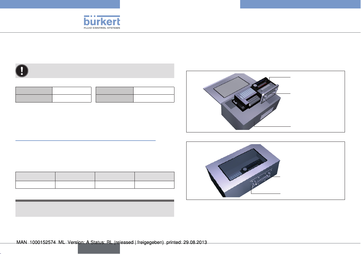
6.2.1. Installation on standard rail
Converter
Module
Field bus
Module
Converter
Terminator
Fig. 4: Installation of a valve block into a control cabinet
english
9
Page 10
Type 8644
Assembly
→ Fasten the standard rail firmly in the control cabinet.
→ Establish a short, wide PE connection between the standard rail
and the control cabinet.
The valve terminal must be freely accessible from above.
Ensure good heat dissipation!
Recommended distance when installing in a control cabinet:
A
B
30 mm
30 mm
C
D
6.2.2. Installation of AirLINE Quick
To install AirLINE Quick, a notch must be first of all provided on the
base or the wall of the control cabinet, e.g. through lasing or punching.
For the dimensions of the relevant flange image, refer to chapter
“Tab. 1: Dimensions of the flange images for AirLINE Quick”.
The distances to the left, right, front and top depend on the selected
valve terminal configuration.
Recommended distance in the control cabinet to the valve
terminal:
left right front top
30 mm 60 mm 30 mm 50 mm
HINWEIS!
The opening on the control cabinet must be burr-free to
prevent damage to the seal of the AirLINE Quick adapter.
30 mm
60 mm
→ Position the valve terminal in the control cabinet on the prepared
opening.
→ From outside attach the stability plate to prevent distortion and
secure with screws M 5 x 10 from the enclosed fastening set.
Valve terminal
Type 8644
AirLINE Quick
adapter
Control cabinet
Fig. 5: Placing the valve terminal in the control cabinet
Screws M 5 x 10
Stability plate
Fig. 6: Attaching the stability plate
→ Without damaging the seal of the AirLINE Quick adapter, insert it
into the groove of the flange opening.
10
english
Page 11

Type 8644
Assembly
6.2.3. Dimensions of the flange images for AirLINE Quick
Inside wall control cabinet
N4
N3
N2
t>=1.5
>=8
N1
Ø 5.3 ± 0.2
R 6.5
only at O= 6 and O = 10
M
G
Space requirements reinforcing frame outside
Fig. 7: Dimensions of the flange images for AirLINE Quick – for dimensions see “Tab. 1”, page 12
english
59 ± 0.3
73 ± 0.3
(96)
11
Page 12
Type 8644
Assembly
Version
8-fold 12-fold 16-fold 16-fold 20-fold
Feature
M
N1
N2
N3
N4
O (Number of
bores)
G
– – –
155 ±0.4 199 ±0.4 243 ±0.4 276 ±0.4 287 ±0.4
54 ±0.3 68 ±0.3 123 ±0.4 140 ±0.4 145 ±0.4
158 ±0.4 202 ±0.4 246 ±0.4 279 ±0.4 290 ±0.4
– – – – –
– – – – –
8 8 10 10 10
192 236 280 313 324
1) 2)
20-fold 24-fold 24-fold 32-fold
Feature
M
N1
N2
N3
N4
O (Number of
bores)
G
Tab. 1: Dimensions of the flange images for AirLINE Quick
1) with intermediate feed
2) on request
3) with intermediate feed on request
3)
320 ±0.4 331 ±0.4 364 ±0.4 452 ±0.4
65 ±0.3 66 ±0.3 73 ±0.3 65 ±0.3
193 ±0.4 200 ±0.4 219 ±0.4 195 ±0.4
323 ±0.4 334 ±0.4 367 ±0.4 325 ±0.4
– – –
12 12 12 16
357 368 401 489
–
1) 3)
455 ±0.4
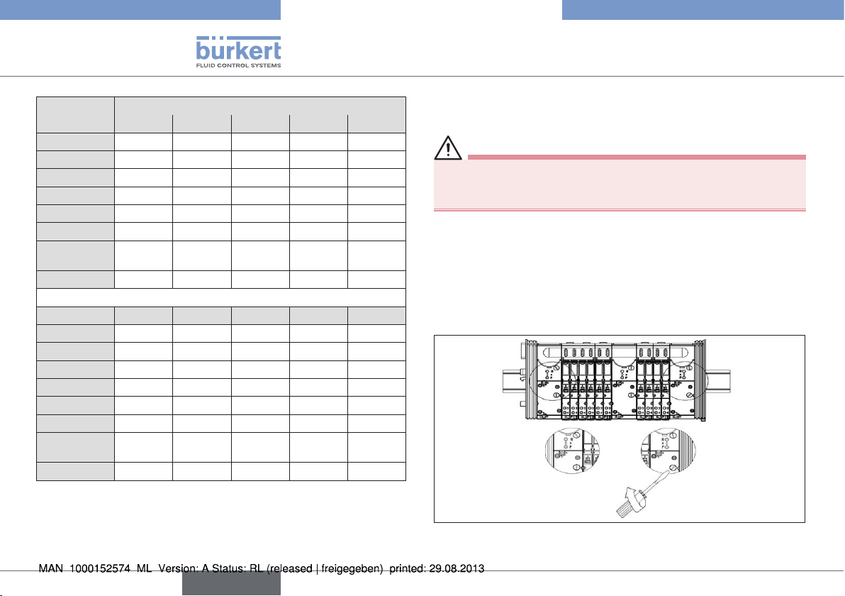
6.3. Removing the valve block from the
standard rail
DANGER!
Risk of electric shock!
• Before reaching into the device or the equipment, switch off the
power supply and secure to prevent reactivation.
The valve block is bolted securely onto the standard rail. Additional
electrical modules / terminals can be aligned in rows on the sides of
the valve block.
Procedure:
→ Detach the adjacent modules/terminals (if fitted).
→ Release the attachment of the valve block on the standard rail. To
do this, turn the fastening screws all the way counter-clockwise.
Fig. 8: Releasing the attachment of the valve block on the standard rail
→ Lift the valve block vertically off the standard rail.
12
english
Page 13

Type 8644
Installation
There must be adequate space between valve block and predecessor module > 6 mm.
→ Detach the modules/terminals from the standard rail according to
the manufacturer’s description.
NOTE!
The interface of the left connection module contains elements
which may break off if force is used.
• Never place the valve block on its side and observe the permitted
installation position.
Fig. 9: Detaching the modules/terminals from the standard rail
NOTE!
•
When screwing the valve block back onto the standard rail,
observe a max. torque of 2 Nm!
7. INSTALLATION
7.1. Fluid Installation
DANGER!
Risk of injury from high pressure in the equipment!
• Before loosening lines or valves, turn off the pressure and vent
the lines.
• Design the connections with the largest possible volume.
• Close the open connections not required with lock screws.
• The connections for the pilot control exhaust air (x) must not be
sealed.
Check correct assignment of the connections 1 and 3 or 5. They
•
may by no means be interchanged.
7.1.1. Pneumatic connections - feed
Exhaust air
X channel:
Standard version:
Deaeration of the control valves
Control assist air version:
P connection for control valves
Pressure supply connection
Fig. 10: Pneumatic Connections
Procedure:
→ Depending on the version, plug the connections in the corre-
sponding working connections or screw them in.
english
13
Page 14

Type 8644
Installation
NOTE!
For the plug-in connections the hose pipes must meet the following
requirements:
•
Minimum hardness of 40 Shore D (in accordance with DIN
53505 or ISO 868);
• Outer diameter in accordance with DIN 73378 (max. permitted
deviation ± 0.1 mm of the nominal dimension);
• Burr-free, cut off at right angles and undamaged on the outer
diameter;
The hose pipes must be pressed all the way into the plug-in
connections.
7.1.2. Removing the plug-in connections
→ To detach the pipes, press in the thrust ring and pull out the hose
pipe.
7.1.3. Pneumatic connections –
AirlINE standard
Inscription areas
Working connections
for 5/2-way valves
Working connections
for 3/2-way valves
Fig. 11: Pneumatic connections - valve discs
Procedure:
→ Depending on the version, plug the connections in the corre-
sponding working connections or screw them in.
→ Connection nipples can be used for threaded versions.
Inscription of the connections:
→ Label the inscription areas with the data of the valve
connections.
7.1.4. Pneumatic connections –
AirLINE Quick
Fig. 12: Pneumatic connections – AirLINE Quick
Procedure:
→ Depending on the version, plug the connections in the corre-
sponding working connections.
14
english
Page 15

Type 8644
Installation
7.1.5. Fluid connection AirLINE Quick
Example of
connection adapter
Air discharge connection R/S
Supply connection P
Fig. 13: Fluid connection AirLINE Quickk
Procedure:
→ Screw connection adapter G1/4" or NPT 1/4" to connections P
and R/S.
NOTE!
Risk of leakage if screw connection is too tight!
• When fitting the fluid connection adapters to the connections
P, R/S, observe the max. torque of 12 Nm. In doing so, counter
with a suitable tool to prevent the connections from turning!
7.2. Fluid deinstallation
NOTE!
Irreversible damage to the seal in the thread of the screw
connection!
When loosening the connection adapters, use a suitable tool to
•
prevent the corresponding supply or air discharge connection
from turning.
7.3. Electrical Installation
DANGER!
Risk of injury due to electrical shock!
• Before reaching into the device or the equipment, switch off the
power supply and secure to prevent reactivation!
The electrical installation of the AirLINE system corresponds to the
installation of the decentralized peripheral device (depending on the
relevant cooperation partner Siemens, Wago, Phoenix or Rockwell).
Refer to the manuals provided by the cooperation partners for a more
detailed description.
english
15
Page 16

Type 8644
Start-Up
8. START-UP
8.1. Safety instructions
WARNING!
Risk of injury from improper operation!
Improper operation may result in injuries as well as damage to the
device and the area around it.
• Before start-up, ensure that the operating personnel are familiar
with and completely understand the contents of the operating
instructions.
Observe the safety instructions and intended use.
•
• Only adequately trained personnel may start up the equipment/
the device.
8.2. Fluid start-up
NOTE!
•
Switch on the supply pressure.
• Only then switch on the power supply!
Procedures before fluid start-up:
→ Check connections, voltage and operating pressure.
→ Ensure that max. operating data are not exceeded.
→ Check correct assignment of the connections 1 and 3 or 5. They
may by no means be interchanged.
→ Release manual actuation during electrical operation.
8.3. Electrical start-up
The start-up of the AirLINE system corresponds to the installation of the
decentralized peripheral device (depending on the relevant cooperation
partner Siemens, Wago, Phoenix or Rockwell).
Refer to the manuals provided by the cooperation partners for a more
detailed description.
9. MAINTENANCE
See“7.2. Fluid deinstallation”, page 15.
10. TRANSPORT, STORAGE, DISPOSAL
NOTE!
Transport damages!
Inadequately protected equipment may be damaged during transport.
• During transportation protect the device against wet and dirt in
shock-resistant packaging.
• Avoid exceeding or dropping below the permitted storage
temperature.
Incorrect storage may damage the device!
• Store the device in a dry and dust-free location!
• Storage temperature: -20 ... +60 °C.
Damage to the environment caused by device components
contaminated with media!
• Ensure the device and packaging are disposed of in an environmentally sound manner.
• Observe applicable regulations relating to refuse disposal and
the environment.
• Observe the national waste disposal regulations.
16
english
Page 17

Typ 8644
Inhaltsverzeichnis
1. DER QUICKSTART ....................................................................................... 18
1.1. Begriffsdefinition Gerät .................................................................18
1.2. Darstellungsmittel
2. BESTIMMUNGSGEMÄSSE VERWENDUNG ...................................19
2.1. Beschränkungen
3. GRUNDLEGENDE SICHERHEITSHINWEISE ................................. 19
4. ALLGEMEINE HINWEISE .......................................................................... 20
4.1. Kontaktadresse
4.2. Gewährleistung...............................................................................20
4.3. Informationen im Internet ..............................................................20
5. TECHNISCHE DATEN ................................................................................ 21
5.1. Konformität
5.2. Normen
5.3. Allgemeine technische Daten ......................................................21
.............................................................................................21
...........................................................................18
............................................................................19
...............................................................................20
.......................................................................................21
6. MONTAGE
6.1. Sicherheitshinweise
6.2. Montage
6.3. Entfernen des Ventilblocks von der Normschiene ..................26
7. INSTALLATION
7.1. Fluidische Installation ....................................................................27
7.2. Fluidische Deinstallation ...............................................................29
7.3. Elektrische Installation ...................................................................29
8. INBETRIEBNAHME
8.1. Sicherheitshinweise
8.2. Fluidische Inbetriebnahme ...........................................................30
8.3. Elektrische Inbetriebnahme ..........................................................30
9. WARTUNG
10. TRANSPORT, LAGERUNG, VERPACKUNG ..................................30
........................................................................................................ 22
.......................................................................22
...........................................................................................23
...............................................................................................27
......................................................................................30
.......................................................................30
........................................................................................................30
deutsch
17
Page 18

Typ 8644
Der Quickstart
1. DER QUICKSTART
Der Quickstart beschreibt den gesamten Lebenszyklus des Geräts.
Bewahren Sie diese Anleitung so auf, dass sie für jeden Benutzer gut
zugänglich ist und jedem neuen Eigentümer des Geräts wieder zur
Verfügung steht.
Wichtige Informationen zur Sicherheit!
Lesen Sie den Quickstart sorgfältig durch. Beachten Sie vor allem
die Kapitel „Grundlegende Sicherheitshinweise“ und „Bestimmungsgemäße Verwendung“.
Der Quickstart muss gelesen und verstanden werden.
•
Der Quickstart erläutert beispielhaft die Montage und Inbetriebnahme
des Geräts. Die ausführliche Beschreibung des Geräts finden Sie in
der Bedienungsanleitung für den Typ 8644.
Die Bedienungsanleitung finden Sie auf der beigelegten CD
oder im Internet unter: www.buerkert.de
1.1. Begriffsdefinition Gerät
Der in dieser Anleitung verwendeten Begriff „Gerät“ steht immer für
das System AirLINE Typ 8644.
1.2. Darstellungsmittel
In dieser Anleitung werden folgende Darstellungsmittel verwendet.
GEFAHR!
Warnt vor einer unmittelbaren Gefahr!
• Bei Nichtbeachtung sind Tod oder schwere Verletzungen die
Folge.
WARNUNG!
Warnt vor einer möglicherweise gefährlichen Situation!
• Bei Nichtbeachtung können schwere Verletzungen oder Tod die
Folge sein.
VORSICHT!
Warnt vor einer möglichen Gefährdung!
• Nichtbeachtung kann mittelschwere oder leichte Verletzungen zur
Folge haben.
HINWEIS!
Warnt vor Sachschäden!
Wichtige Tipps und Empfehlungen.
Verweist auf Informationen in dieser Bedienungsanleitung
oder in anderen Dokumentationen.
18
→ markiert einen Arbeitsschritt den Sie ausführen müssen.
deutsch
Page 19

Typ 8644
Bestimmungsgemäße Verwendung
2. BESTIMMUNGSGEMÄSSE
VERWENDUNG
Bei nicht bestimmungsgemäßem Einsatz der AirLINE Typ 8644
können Gefahren für Personen, Anlagen in der Umgebung und
die Umwelt entstehen.
• Das Gerät ist für den Einsatz in explosionsgefährdeten Umgebungen konzipiert. Es darf zur Steuerung pneumatisch betriebener
Geräte eingesetzt werden.
• In die Medienanschlüsse des Systems keine aggressiven oder
brennbaren Medien einspeisen.
• Das Gerät nicht ungeschützt im Außenbereich einsetzen.
• Das Gehäuse nicht mechanisch belasten (z. B. durch Ablage von
Gegenständen oder als Trittstufe).
• Für den Einsatz die in den Vertragsdokumenten und der Bedienungsanleitung spezifizierten zulässigen Daten, Betriebs- und
Einsatzbedingungen beachten. Diese sind im Kapitel „Technische
beschrieben.
Daten“
• Das Gerät nur in Verbindung mit von Bürkert empfohlenen bzw.
zugelassenen Fremdgeräten und -komponenten einsetzen.
• Voraussetzungen für den sicheren und einwandfreien Betrieb sind
sachgemäßer Transport, sachgemäße Lagerung und Installation
sowie sorgfältige Bedienung und Instandhaltung.
• Setzen Sie das Gerät nur bestimmungsgemäß ein.
2.1. Beschränkungen
Beachten Sie bei der Ausfuhr des Systems/Geräts gegebenenfalls
bestehende Beschränkungen.
3. GRUNDLEGENDE
SICHERHEITSHINWEISE
Diese Sicherheitshinweise berücksichtigen keine
• Zufälligkeiten und Ereignisse, die bei Montage, Betrieb und Wartung
der Geräte auftreten können.
• ortsbezogenen Sicherheitsbestimmungen, für deren Einhaltung, auch
in Bezug auf das Montagepersonal, der Betreiber verantwortlich ist.
Allgemeine Gefahrensituationen.
Zum Schutz vor Verletzungen ist zu beachten:
• Dass die Anlage nicht unbeabsichtigt betätigt werden kann.
• In Systemen, die unter Druck stehen, dürfen Leitungen und Ventile
nicht gelöst werden.
• Vor Eingriffen in das System in jedem Fall die Spannung abschalten.
• Druckversorgung möglichst großvolumig ausführen, um Druckabfall
beim Schalten zu vermeiden.
• Installations- und Instandhaltungsarbeiten dürfen nur von autorisiertem Fachpersonal mit geeignetem Werkzeug ausgeführt werden.
• Das Gerät darf nur in einwandfreiem Zustand und unter Beachtung
der Bedienungsanleitung betrieben werden.
• Nach einer Unterbrechung der elektrischen oder pneumatischen
Versorgung ist ein definierter oder kontrollierter Wiederanlauf des
Prozesses zu gewährleisten.
• Für die Einsatzplanung und den Betrieb des Geräts müssen die
allgemeinen Regeln der Technik eingehalten werden.
deutsch
19
Page 20

Typ 8644
Allgemeine Hinweise
Verbrennungsgefahr/Brandgefahr bei Dauerbetrieb durch
heiße Geräteoberfläche!
• Das Gerät von leicht brennbaren Stoffen und Medien fernhalten
und nicht mit bloßen Händen berühren.
Typ 8644 AirLINE wurde unter Einbeziehung der anerkannten
sicherheitstechnischen Regeln entwickelt und entspricht
dem Stand der Technik. Trotzdem können Gefahren entstehen.
HINWEIS!
Elektrostatisch gefährdete Bauelemente / Baugruppen!
Das Gerät enthält elektronische Bauelemente, die gegen elektrostatische Entladung (ESD) empfindlich reagieren. Berührung mit
elektrostatisch aufgeladenen Personen oder Gegenständen gefährdet
diese Bauelemente. Im schlimmsten Fall werden sie sofort zerstört
oder fallen nach der Inbetriebnahme aus.
• Beachten Sie die Anforderungen nach EN 61340-5-1 und 5-2,
um die Möglichkeit eines Schadens durch schlagartige elektrostatische Entladung zu minimieren bzw. zu vermeiden!
• Achten Sie ebenso darauf, dass Sie elektronische Bauelemente
nicht bei anliegender Versorgungsspannung berühren!
4. ALLGEMEINE HINWEISE
4.1. Kontaktadresse
Deutschland
Bürkert Fluid Control Systems
Sales Center
Christian-Bürkert-Str. 13-17
D-74653 Ingelfingen
Tel. + 49 (0) 7940 - 10 91 111
Fax + 49 (0) 7940 - 10 91 448
E-mail: info@de.buerkert.com
International
Die Kontaktadressen finden Sie auf den letzten Seiten der
gedruckten Bedienungsanleitung oder im Internet: www.burkert.com
4.2. Gewährleistung
Voraussetzung für die Gewährleistung ist der bestimmungsgemäße
Gebrauch der AirLINE Typ 8644 unter Beachtung der spezifizierten
Einsatzbedingungen.
4.3. Informationen im Internet
Bedienungsanleitungen und Datenblätter zum Typ 8644 finden Sie im
Internet unter: www.buerkert.de
20
deutsch
Page 21

Typ 8644
Technische Daten
5. TECHNISCHE DATEN
5.1. Konformität
Das AirLINE System Typ 8644 ist konform zu den EG-Richtlinien
entsprechend der Konformitätserklärung.
5.2. Normen
Die angewandten Normen, mit denen die Konformität mit den EGRichtlinien nachgewiesen wird, sind in der Baumusterprüfbescheinigung und/oder der EG-Konformitätserklärung nachzulesen.
5.3. Allgemeine technische Daten
Technische
Daten
Druckbereich Vak. bis 10 bar Vak. bis 10 bar
Betriebs-
spannung
Spannungs-
toleranz
Umgebungstemperatur
Pilotventil Typ 0460,
6524, 6525
24 V DC 24 V DC
+20 % / –15 %
(bei Verwendung des
Typs 0460: ± 10 %)
0 ... +55 °C
(bei Verwendung des Typs 0460 und 0461:
0 ... +50 °C)
Pilotventil Typ 0461,
6526, 6527
+20 % / –15 %
(bei Verwendung des
Typs 0461: ± 10 %)
5.3.1. Typschild
Typ
Wirkungsweise
Nennweite
6525 H 4,0
PN 2,5 - 7 bar
24 V DC 1W
450000Y
MADE IN GERMANY
Identnummer
Spannung (± 10 %), Leistung
Druckbereich
Bild 1: Lage und Beschreibung des Typschildes
W14UN
deutsch
21
Page 22

Typ 8644
Montage
5.3.2. Fluidischer Anschluss
Typ 6524
X*
3/R
2/A
1/P
Bild 2: Fluidischer Anschluss. Typen 6524 und 6525
Typ 6525
X*
5/R
4/A
1/P
2/B
3/S
Druckversorgung möglichst
großvolumig ausführen!
X* - Vorsteuerabluft
5.3.3. Fluidischer und elektrischer
Anschluss
Typ 6524
(2 x 2/3-Wege Ventil)
– Pol Spule 12
angesteuert über Bit „n+1“
+ Pol
– Pol Spule 14
angesteuert über Bit „n“
Handhebel-
12
zuordnung
14
X* - Vorsteuerabluft
X*
5/R
4/A
1/P
2/B
3/S
Bit „n+1“
Pinbelegung
beachten!
Bit „n“
6. MONTAGE
6.1. Sicherheitshinweise
GEFAHR!
Verletzungsgefahr durch hohen Druck in der Anlage!
• Vor dem Lösen von Leitungen oder Ventilen den Druck abschalten und Leitungen entlüften.
Verletzungsgefahr durch Stromschlag!
• Vor Eingriffen in das Gerät oder die Anlage die Spannung abschalten und vor Wiedereinschalten sichern!
• Die geltenden Unfallverhütungs- und Sicherheitsbestimmungen für
elektrische Geräte beachten!
WARNUNG!
Verletzungsgefahr bei unsachgemäßer Montage!
• Die Montage darf nur autorisiertes Fachpersonal mit geeignetem
Werkzeug durchführen!
Verletzungsgefahr durch ungewolltes Einschalten der Anlage
und unkontrollierten Wiederanlauf!
• Anlage vor unbeabsichtigtem Betätigen sichern.
• Nach der Montage einen kontrollierten Wiederanlauf
gewährleisten.
Bild 3: Fluidischer und elektrischer Anschluss. Typ 6524
22
deutsch
Page 23

Typ 8644
Montage
VORSICHT!
Mediumsaustritt und Fehlfunktion!
Bei mangelhaftem Sitz der Dichtungen können Undichtigkeiten und
Funktionsbeeinträchtigungen durch Druckverluste auftreten.
• Auf korrekten Sitz der Dichtungen im Bereich der Elektronik und
Pneumatik achten.
Kurzschluss, Funktionsausfall!
Der elektrische Anschluss erfordert exakte Kontaktierung.
• Kontakte nicht verbiegen.
• Bei beschädigten oder verbogenen Anschlüssen die betroffenen
Komponenten austauschen.
• Das System nur bei einwandfreiem Zustand der Komponenten
einschalten.
HINWEIS!
System nur mit Gleichstrom betreiben!
Um Schäden am System zu vermeiden für die Stromversorgung des
Systems ausschließlich Gleichstrom einsetzen.
Druckabfall vermeiden!
Um einen Druckabfall zu vermeiden die Druckversorgung des
Systems möglichst großvolumig ausführen.
6.2. Montage
GEFAHR!
Explosionsgefahr!
Bei Systemen im explosionsgeschützten Bereich, die in einem
Schaltschrank eingesetzt sind, muss folgendes sichergestellt sein:
• Der Schaltschrank muss für den Einsatz im explosionsgeschützten Bereich zugelassen sein.
• Der Schaltschrank muss so groß dimensioniert werden, dass die
entstehende Verlustwärme in geeigneter Weise nach außen abgeführt werden kann.
• Die Innentemperatur des Schaltschranks darf die maximal zulässige Umgebungstemperatur für das Gerät nicht überschreiten.
Gefahr durch elektrische Spannung!
• Vor Eingriffen in das Gerät oder die Anlage Spannung abschalten
und vor Wiedereinschalten sichern!
6.2.1. Montage auf der Normschiene
Umsetzer
Modul
Feldbus
Modul
Umsetzer
Abschluss
Bild 4: Einbau des Ventilblocks in einen Schaltschrank
deutsch
23
Page 24

Typ 8644
Montage
→ Die Normschiene fest im Schaltschrank montieren.
→ Eine kurze, breite PE-Verbindung zwischen Normschiene und
Schaltschrank herstellen.
Die Ventilinsel muss nach oben frei zugänglich sein.
Für gute Wärmeabfuhr sorgen!
Abstandsempfehlung beim Einbau in den Schaltschrank:
A
B
30 mm
30 mm
C
D
6.2.2. Montage AirLINE Quick
Zur Montage von AirLINE Quick muss zuerst ein Ausbruch am Schaltschrankboden bzw. der Schaltschrankwand vorgesehen werden. Dies
kann z. B. durch Lasern oder Stanzen erfolgen.
Die Abmessungen des entsprechenden Flanschbildes siehe Kapitel
„6.2.3. Abmessungen der Flanschbilder für AirLINE Quick“.
Die Abstände nach links, rechts, vorne und oben sind abhängig von
der gewählten Ventilinselkonfiguration.
Empfehlung Abstand im Schaltschrank zur Ventilinsel:
links rechts vorne oben
30 mm 60 mm 30 mm 50 mm
HINWEIS!
Der Ausbruch am Schaltschrank muss gratfrei sein, damit die
Dichtung des AirLINE Quick Adapters nicht beschädigt wird.
30 mm
60 mm
→ Die Ventilinsel im Schaltschrank auf den vorbereiteten Ausbruch
platzieren.
→ Von außen das Stabilisierungsblech zur Vermeidung von Verwer-
fungen anbringen und mit Schrauben M 5 x 10 des beiliegenden
Befestigungssatzes befestigen.
Ventilinsel
Typ 8644
AirLINE Quick
Adapter
Schaltschrank
Bild 5: Platzieren der Ventilinsel im Schaltschrank
Schrauben M 5 x 10
Stabilisierungsblech
Bild 6: Befestigung des Stabilisierungsblechs
→ Dichtung des AirLINE Quick Adapters beschädigungsfrei in die
Nut der Flanschöffnung einlegen.
24
deutsch
Page 25

Typ 8644
Montage
6.2.3. Abmessungen der Flanschbilder für AirLINE Quick
Schaltschrank-Innenwand
N4
N3
N2
t>=1,5
>=8
N1
Ø 5,3 ± 0,2
R 6,5
Platzbedarf Versteifungsrahmen Außenseite
Bild 7: Flanschbilder AirLINE Quick – Maße siehe Tab. 1 auf Seite 26
nur bei O= 6 und O = 10
M
G
deutsch
59 ± 0,3
73 ± 0,3
(96)
25
Page 26

Typ 8644
Montage
Ausführung
8-fach 12-fach 16-fach 16-fach 20-fach
Besonderheit
M
N1
N2
N3
N4
O (Anzahl
Bohrungen)
G
– – –
155 ±0,4 199 ±0,4 243 ±0,4 276 ±0,4 287 ±0,4
54 ±0,3 68 ±0,3 123 ±0,4 140 ±0,4 145 ±0,4
158 ±0,4 202 ±0,4 246 ±0,4 279 ±0,4 290 ±0,4
– – – – –
– – – – –
8 8 10 10 10
192 236 280 313 324
20-fach 24-fach 24-fach 32-fach
Besonderheit
M
N1
N2
N3
N4
O (Anzahl
Bohrungen)
G
Tab. 1: Abmessungen Flanschbilder AirLINE Quick
1) mit Zwischeneinspeisung
2) auf Anfrage
3) mit Zwischeneinspeisung auf Anfrage
3)
320 ±0,4 331 ±0,4 364 ±0,4 452 ±0,4
65 ±0,3 66 ±0,3 73 ±0,3 65 ±0,3
193 ±0,4 200 ±0,4 219 ±0,4 195 ±0,4
323 ±0,4 334 ±0,4 367 ±0,4 325 ±0,4
– – –
12 12 12 16
357 368 401 489
–
1) 3)
1) 2)
455 ±0,4
6.3. Entfernen des Ventilblocks von der
Normschiene
GEFAHR!
Gefahr durch elektrische Spannung!
• Vor Eingriffen in das Gerät oder die Anlage Spannung abschalten
und vor Wiedereinschalten sichern.
Der Ventilblock ist fest auf der Normschiene verschraubt. An seinen
Seiten können weitere elektrische Module/Klemmen angereiht sein.
Vorgehensweise:
→ Die benachbarten Module/Klemmen (falls vorhanden) lösen.
→ Befestigung des Ventilblocks an der Normschiene entriegeln.
Hierzu die Befestigungsschrauben gegen den Uhrzeigersinn bis
zum Anschlag drehen.
Bild 8: Entriegeln der Befestigung des Ventilblocks an der Normschiene
→ Ventilblock senkrecht von der Normschiene abheben.
26
deutsch
Page 27

Typ 8644
Installation
Es muss genügend Platz zwischen Ventilblock und Vorgängermodul sein > 6 mm.
→ Module/Klemmen entsprechend der Herstellerbeschreibung von
der Normschiene lösen.
HINWEIS!
Die Schnittstelle des linken Anschlussmoduls beinhaltet
Elemente, die bei Gewalteinwirkung abbrechen können.
• Ventilblock nie auf die Seite stellen und zulässige Einbaulage
beachten.
Bild 9: Lösen der Modulen/Klemmen von der Normschiene
HINWEIS!
•
Beim Wiederverschrauben des Ventilblocks auf der Normschiene ein max. Drehmoment von 2 Nm beachten!
7. INSTALLATION
7.1. Fluidische Installation
GEFAHR!
Verletzungsgefahr durch hohen Druck in der Anlage!
• Vor dem Lösen von Leitungen oder Ventilen den Druck abschalten
und Leitungen entlüften.
• Die Anschlüsse möglichst großvolumig ausführen.
• Nicht benötigte offene Anschlüsse mit Verschlussschrauben
schließen.
Anschlüsse für Vorsteuerabluft (x) dürfen nicht verschlossen werden.
•
• Die vorschriftsmäßige Belegung der Anschlüsse 1 und 3 bzw. 5
überprüfen. Diese dürfen auf keinen Fall vertauscht werden.
7.1.1. Pneumatische Anschlüsse –
Einspeisung
Abluft R/3, S/5
X-Kanal
Standardausführung:
Entlüftung der Steuerventile
Steuerhilfsluftausführung:
P-Anschluss für Steuerventile
Druckversorgungsanschluss P/1
Bild 10: Pneumatische Anschlüsse
Vorgehensweise:
→ Die Anschlüsse je nach Ausführung an den entsprechenden
Arbeitsanschlüssen einstecken oder einschrauben.
deutsch
27
Page 28

Typ 8644
Installation
HINWEIS!
Für die Steckanschlüsse müssen die Schlauchleitungen folgende
Anforderungen erfüllen:
• Mindesthärte von 40 Shore D (nach DIN 53505 bzw. ISO 868),
• Außendurchmesser entsprechend DIN 73378 (max. zul. Abweichung ± 0,1 mm vom Nennmaß),
• gratfrei, rechtwinklig abgeschnitten und am Außendurchmesser
unbeschädigt.
Die Schlauchleitungen sind bis zum Anschlag in die Steckanschlüsse
einzudrücken.
7.1.2. Demontage der Steckanschlüsse
→ Zum Lösen der Leitungen den Druckring eindrücken und die
Schlauchleitung herausziehen.
7.1.3. Pneumatische Anschlüsse –
AirLINE Standard
Beschriftungsfelder
Arbeitsanschlüsse bei
5/2-Wege-Ventilen
Arbeitsanschlüsse bei
3/2-Wege-Ventilen
Bild 11: Pneumatische Anschlüsse – Ventilscheiben
Vorgehensweise:
→ Die Anschlüsse je nach Ausführung an entsprechenden Arbeits-
anschlüssen einstecken oder einschrauben.
→ Bei Gewindeausführung können Anschlussnippel verwendet
werden.
Beschriftung der Anschlüsse:
→ Beschriftungsfelder mit Daten der Ventilanschlüsse beschriften.
7.1.4. Pneumatische Anschlüsse –
AirLINE Quick
Bild 12: Pneumatische Anschlüsse – AirLINE Quick
Vorgehensweise:
→ Anschlüsse an entsprechenden Arbeitsanschlüssen einstecken.
28
deutsch
Page 29

Typ 8644
Installation
7.1.5. Fluidischer Anschluss AirLINE Quick
Beispiel für
Anschlussadapter
Entlüftungsanschluss R/S
Versorgungsanschluss P
Bild 13: Fluidischer Anschluss AirLINE Quick
Vorgehensweise:
→ Anschlussadapter G1/4 bzw. NPT 1/4 an Anschlüsse P und R/S
schrauben.
HINWEIS!
Gefahr der Leckage bei zu starker Verschraubung!
• Bei Montage der fluidischen Anschlussadapter an die
Anschlüsse P, R/S das max. Drehmoment von 12 Nm beachten.
Hierbei durch Gegenhalten mit einem geeigneten Werkzeug das
Verdrehen der Anschlüsse verhindern!
7.2. Fluidische Deinstallation
HINWEIS!
Irreversible Beschädigung der Dichtung im Gewinde der
Verschraubung!
Beim Lösen der Anschlussadapter das Verdrehen des entspre-
•
chenden Versorgungs- oder Entlüftungsanschlusses mit geeignetem Werkzeug verhindern.
7.3. Elektrische Installation
GEFAHR!
Verletzungsgefahr durch Stromschlag!
• Vor Eingriffen in das Gerät oder die Anlage Spannung abschalten
und vor Wiedereinschalten sichern!
Die elektrische Installation des AirLINE Systems entspricht der
Installation des dezentralen Peripheriegeräts (abhängig vom jeweiligen
Kooperationspartner Siemens, Wago, Phoenix oder Rockwell).
Alle hier notwendigen Schritte sind den jeweiligen Handbüchern der
Kooperationspartner zu entnehmen.
deutsch
29
Page 30

Typ 8644
Inbetriebnahme
8. INBETRIEBNAHME
8.1. Sicherheitshinweise
WARNUNG!
Verletzungsgefahr bei unsachgemäßem Betrieb!
Nicht sachgemäßer Betrieb kann zu Verletzungen sowie Schäden
am Gerät und seiner Umgebung führen.
• Vor der Inbetriebnahme muss gewährleistet sein, dass der Inhalt
der Bedienungsanleitung dem Bedienungspersonal bekannt ist
und vollständig verstanden wurde.
• Die Sicherheitshinweise und die bestimmungsgemäße Verwendung müssen beachtet werden.
• Nur ausreichend geschultes Personal darf die Anlage/das Gerät
in Betrieb nehmen.
8.2. Fluidische Inbetriebnahme
HINWEIS!
•
Schalten Sie den Versorgungsdruck ein.
• Schalten Sie erst danach die Spannung ein!
Maßnahmen vor der fluidischen Inbetriebnahme:
→ Anschlüsse, Spannung und Betriebsdruck überprüfen.
→ Beachten, dass max. Betriebsdaten nicht überschritten werden.
→ Die vorschriftsmäßige Belegung der Anschlüsse 1 und 3 bzw. 5
überprüfen. Diese dürfen auf keinen Fall vertauscht werden.
→ Bei elektrischem Betrieb die Handbetätigung entriegeln.
8.3. Elektrische Inbetriebnahme
Die Inbetriebnahme des AirLINE Systems entspricht der Installation
des dezentralen Peripheriegeräts (abhängig vom jeweiligen Kooperationspartner Siemens, Wago, Phoenix oder Rockwell).
Alle hier notwendigen Schritte sind den jeweiligen Handbüchern der
Kooperationspartner zu entnehmen.
9. WARTUNG
Siehe„7.2. Fluidische Deinstallation“ auf Seite 29.
10. TRANSPORT, LAGERUNG,
VERPACKUNG
HINWEIS!
Transportschäden!
Unzureichend geschützte Geräte können durch den Transport
beschädigt werden.
• Gerät vor Nässe und Schmutz geschützt in einer stoßfesten
Verpackung transportieren.
• Eine Über- bzw. Unterschreitung der zulässigen Lagertemperatur
vermeiden.
Falsche Lagerung kann Schäden am Gerät verursachen!
• Gerät trocken und staubfrei lagern!
• Lagertemperatur: -20 ... +60 °C.
Umweltschäden durch von Medien kontaminierte Geräteteile!
• Gerät und Verpackung umweltgerecht entsorgen!
• Geltende Entsorgungsvorschriften und Umweltbestimmungen
einhalten.
•
Die nationalen Abfallbeseitigungsvorschriften beachten.
30
deutsch
Page 31

Type 8644
Sommaire
1. QUICKSTART ..................................................................................................32
1.1. Définition du terme appareil .........................................................32
1.2. Symboles..........................................................................................32
2. UTILISATION CONFORME.......................................................................33
2.1. Restrictions
3. CONSIGNES DE SÉCURITÉ GÉNÉRALES .....................................33
4. INDICATIONS GÉNÉRALES .................................................................... 34
4.1. Adresse
4.2. Garantie légale ................................................................................34
4.3. Information sur Internet .................................................................34
5. CARACTÉRISTIQUES TECHNIQUES ................................................35
5.1. Conformité
5.2. Normes
5.3. Caractéristiques techniques générales ....................................35
......................................................................................33
............................................................................................34
.......................................................................................35
.............................................................................................35
6. MONTAGE
6.1. Consignes de sécurité ..................................................................36
6.2. Montage
6.3. Retrait du bloc de vannes du rail normalisé .............................40
7. INSTALLATION
7.1. Installation fluidique .......................................................................41
7.2. Désinstallation fluidique ................................................................44
7.3. Installation électrique .....................................................................44
8. MISE EN SERVICE ....................................................................................... 44
8.1. Consignes de sécurité ..................................................................44
8.2. Mise en service fluidique ..............................................................44
8.3. Mise en service électrique ...........................................................45
9. ENTRETIEN
10. TRANSPORT, STOCKAGE, ÉLIMINATION ..................................... 45
........................................................................................................ 36
...........................................................................................37
...............................................................................................41
...................................................................................................... 45
français
31
Page 32

Type 8644
Quickstart
1. QUICKSTART
Quickstart décrit le cycle de vie complet de l’appareil. Conservez-le
de sorte qu’il soit accessible à tout utilisateur et à disposition de tout
nouveau propriétaire.
Informations importantes pour la sécurité !
Lisez attentivement Quickstart. Tenez compte en particulier des chapitres « Consignes de sécurité générales » et « Utilisation conforme ».
Les instructions de service Quickstart doivent être lues et
•
comprises.
Quickstart explique par des exemples le montage et la mise en service
de l’appareil.
Vous trouverez la description détaillée de l’appareil dans le manuel
d’utilisation du type 8644.
Vous trouverez les instructions de service sur le cédérom joint
ou sur internet sous :
www.buerkert.fr
1.1. Définition du terme appareil
Le terme « appareil » utilisé dans ces instructions désigne toujours le
système AirLINE type 8644.
1.2. Symboles
Les moyens de représentation suivants sont utilisés dans les présentes
instructions de service.
DANGER !
Met en garde contre un danger imminent !
• Le non-respect peut entraîner la mort ou de graves blessures.
AVERTISSEMENT !
Met en garde contre une situation éventuellement dangereuse !
• Risque de blessures graves, voire la mort en cas de non-respect.
ATTENTION !
Met en garde contre un risque possible !
• Le non-respect peut entraîner des blessures légères ou de
moyenne gravité.
REMARQUE !
Met en garde contre des dommages matériels !
Conseils et recommandations importants.
Renvoie à des informations dans ces instructions de service
ou dans d’autres documentations.
32
→ identifie une opération que vous devez effectuer.
français
Page 33

Type 8644
Utilisation conforme
2. UTILISATION CONFORME
L’utilisation non conforme de l’AirLINE du type 8644 peut présenter des dangers pour les personnes, les installations proches
et l’environnement.
• L’appareil est conçu pour un emploi dans les environnements présentant des risques d’explosion. Il peut être utilisé pour commander
des appareils à entraînement pneumatique.
• Ne pas alimenter les raccords du système en fluides agressifs
ou inflammables.
• N’utilisez pas l’appareil à l’extérieur sans protection.
• Ne pas soumettre le corps à des contraintes mécaniques (par ex.
pour déposer des objets ou en l’utilisant comme marche).
• Lors de l’utilisation, il convient de respecter les données et conditions d’utilisation et d’exploitation admissibles spécifiées dans
les instructions de service et dans les documents contractuels.
Celles-ci sont décrites au chapitre « Caractéristiques techniques ».
L’appareil peut être utilisé uniquement en association avec les
•
appareils et composants étrangers recommandés et homologués
par Bürkert.
• Les conditions pour l’utilisation sûre et parfaite sont un transport,
un stockage et une installation dans les règles ainsi qu’une parfaite
utilisation et maintenance.
• Veillez à ce que l’utilisation de l’appareil soit toujours conforme.
2.1. Restrictions
Lors de l’exportation du système / de l’appareil, veuillez respecter les
restrictions éventuelles existantes.
3. CONSIGNES DE SÉCURITÉ
GÉNÉRALES
Les présentes consignes de sécurité ne tiennent pas compte :
• Des circonstances fortuites et des événements qui peuvent survenir
lors du montage, du fonctionnement et de la maintenance.
• Des prescriptions de sécurité applicables au niveau local, dont le
respect relève de la responsabilité de l’exploitant, y compris pour le
personnel de montage.
Situations dangereuses d’ordre général.
Pour prévenir les blessures, respectez ce qui suit :
• L’installation ne peut pas être actionnée par inadvertance.
• Notez que, dans les systèmes sous pression, il est interdit de
desserrer les conduites et les vannes.
• Avant d’intervenir dans le système, coupez en tous les cas la tension.
• Dimensionnez la pression d’alimentation le plus généreusement
possible, afin d’éviter les chutes de pression lors de la commutation.
• Les travaux d’installation et de maintenance doivent être effectués
uniquement par des techniciens qualifiés et habilités disposant de
l’outillage approprié.
• Après une interruption de l’alimentation électrique ou pneumatique,
un redémarrage défini ou contrôlé du processus doit être garanti.
• L’appareil doit être utilisé uniquement en parfait état et en respectant les instructions de service.
• Les règles générales de la technique sont d’application pour
planifier l’utilisation et utiliser l’appareil.
français
33
Page 34

Type 8644
Indications générales
isque de brûlures/d’incendie en fonctionnement continu dû à
des surfaces d’appareils brûlantes !
• Tenez les substances et les fluides facilement inflammables à l’écart
de l’appareil et ne touchez pas ce dernier à mains nues.
L’AirLINE du type 8644 a été développé dans le respect des
règles reconnues en matière de sécurité et correspond à l’état
actuel de la technique. Néanmoins, des risques peuvent se
présenter.
REMARQUE !
Eléments/sous-groupes sujets aux risques électrostatiques !
L’appareil contient des éléments électroniques sensibles aux
décharges électrostatiques (ESD). Ces éléments sont affectés
par le contact avec des personnes ou des objets ayant une charge
électrostatique. Au pire, ils sont immédiatement détruits ou tombent
en panne après mise en service.
• Respectez les exigences selon EN 61340-5-1 et 5-2 pour minimiser ou éviter la possibilité d’un dommage causé par une soudaine
décharge électrostatique !
• Veillez également à ne pas toucher d’éléments électroniques
lorsqu’ils sont sous tension d’alimentation !
4. INDICATIONS GÉNÉRALES
4.1. Adresse
Allemagne
Bürkert Fluid Control Systems
Sales Center
Christian-Bürkert-Str. 13-17
D-74653 Ingelfingen
Tel. + 49 (0) 7940 - 10 91 111
Fax + 49 (0) 7940 - 10 91 448
E-mail : info@de.buerkert.com
International
Les adresses se trouvent aux dernières pages des présentes instructions de service.
Également sur Internet sous : www.burkert.com
4.2. Garantie légale
La condition pour bénéficier de la garantie légale est l’utilisation
conforme de l’appareil type 8644 AirLINE dans le respect des conditions d’utilisation spécifiées.
4.3. Information sur Internet
Les manuels d’utilisation et les fiches techniques concernant le type
8644 peuvent être consultés sur Internet sous : www.buerkert.fr
34
français
Page 35

Type 8644
Caractéristiques techniques
5. CARACTÉRISTIQUES TECHNIQUES
5.1. Conformité
Le systéme AirLINE type 8644 est conforme aux directives CE
comme stipulé dans la déclaration de conformité CE.
5.2. Normes
Les normes appliquées justifiant la conformité aux directives CE
peuvent être consultées dans le certificat d’essai de modèle type CE
et / ou la déclaration de Conformité CE.
5.3. Caractéristiques techniques
générales
Caractéristiques
techniques
Plage de pression Vide jusqu'à 10 bar Vide jusqu'à 10 bar
Tension de
service
Tolérance de
tension
Température
ambiante
Vanne pilote types
0460, 6524, 6525
24 V DC 24 V DC
+20 % / -15 %
(lors utilisation du
type 0460 : ± 10 %)
0 ... +55 °C
(lors utilisation des types 0460 et 0461 :
0 ... +50 °C)
Vanne pilote types
0461, 6526, 6527
+20 % / -15 %
(lors utilisation du
type 0461 : ± 10 %)
5.3.1. Plaque signalétique
Type
Fonctionnement
Diamètre nominal
6525 H 4,0
PN 2,5 - 7 bar
24 V DC 1W
450000Y
MADE IN GERMANY
W14UN
Numéro d’identification
Tension (±10 %), puissance
Plage de pression
Fig. 1 : Emplacement et description de la plaque signalétique
français
35
Page 36

Type 8644
montage
5.3.2. Raccord fluidique
Type 6524
X*
3/R
2/A
1/P
Fig. 2 : Raccord fluidique. Types 6524 et 6525
Type 6525
X*
5/R
4/A
1/P
2/B
3/S
Dimensionnez la pression
d’alimentation le plus
généreusement possible !
X* - Air d’échappement de
commande pilote
5.3.3. Raccord fluide et électrique
Type 6524
(Vanne 2 x 3/2 voies)
- Pôle bobine 12
commandé par Bit «n + 1»
+ Pôle
- Pôle bobine 14
commandé par Bit «n»
Respecter l’affectation
des broches !
Affectation du
12
14
levier à main
X*- Air d’échappement
X*
5/R
4/A
1/P
2/B
3/S
Bit «n+1»
de commande pilote
Bit «n»
6. MONTAGE
6.1. Consignes de sécurité
DANGER !
Risque de blessures dû à la présence de haute pression dans
l’installation !
• Avant de desserrer les conduites et les vannes, coupez la pression et purgez l’air des conduites.
Risque de choc électrique !
• Avant d’intervenir dans l’appareil ou l’installation, coupez la tension et empêchez toute remise sous tension par inadvertance !
• Veuillez respecter les réglementations en vigueur pour les appareils électriques en matière de prévention des accidents ainsi
qu’en matière de sécurité !
AVERTISSEMENT !
Risque de blessures dû à un montage non conforme !
• Le montage doit être effectué uniquement par un personnel qualifié
et habilité disposant de l’outillage approprié !
Risque de blessures dû à la mise en marche involontaire de
l’installation et le redémarrage non contrôlé !
• Empêchez tout actionnement involontaire de l’installation.
• Garantissez un redémarrage contrôlé après le montage.
Fig. 3 : Raccord fluide et électrique. Type 6524
36
français
Page 37

Type 8644
montage
ATTENTION !
Sortie de fluide et dysfonctionnement !
Des joints mal positionnés peuvent provoquer des fuites et entraver
le bon fonctionnement suite à des pertes de pression.
• Veillez au bon positionnement des joints dans la zone électronique
et pneumatique.
Court-circuit, panne !
Le raccordement électrique nécessite un contact parfait.
• Ne pliez pas les contacts.
• Remplacez les composants présentant des raccords endommagés
ou pliés.
• Ne mettez le système en service que si les composants sont en
parfait état.
REMARQUE !
Utilisez le système uniquement en courant continu !
Alimentez le système uniquement en courant continu pour ne pas
l’endommager.
Evitez les chutes de pression !
Pour éviter les chutes de pression, dimensionnez la pression d’ali-
mentation du système le plus généreusement possible.
6.2. Montage
DANGER !
Risque d’explosion !
Pour les systèmes utilisés dans une armoire électrique dans une zone
protégée contre les explosions, il faut s’assurer que :
• L’armoire électrique est homologuée pour utilisation dans une zone
protégée contre les explosions.
• Le dimensionnement de l’armoire électrique doit permettre, de
façon appropriée, l’évacuation vers l’extérieur de la chaleur dissipée générée.
• La température à l’intérieur de l’armoire électrique ne doit pas
dépasser la température ambiante maximale admissible de
l’appareil.
Danger présenté par la tension électrique !
• Avant d’intervenir dans l’appareil ou l’installation, coupez la tension
et empêchez toute remise sous tension par inadvertance !
6.2.1. Montage sur le rail normalisé
Convertisseur
Module
Module
Convertisseur
Bus de terrain
Terminaison
français
Fig. 4 : Montage du bloc de vannes dans une armoire électrique
37
Page 38

Type 8644
montage
→ Monter le rail normalisé dans l’armoire électrique.
→ Créer une liaison PE courte et large entre le rail normalisé et
l’armoire électrique.
Le groupe de vannes doit être accessible par le haut.
Assurez-vous d’une bonne dissipation de chaleur !
Conseil de distance lors du montage dans l’armoire électrique :
A
B
30 mm
30 mm
C
D
6.2.2. Montage AirLINE Quick
Pour le montage de l’AirLINE Quick, un percement doit être d’abord
prévu sur le fond ou la paroi de l’armoire électrique. Cela peut se faire
par laser ou poinçonnage.
Les dimensions des réseaux de brides correspondants, voir chapitre
« 6.2.3. Dimensions des réseaux de brides pour AirLINE Quick ».
Les distances par rapport à la gauche, la droite, l’avant et le haut
dépendent du groupe de vannes sélectionné et de la configuration
de celui-ci.
Distance recommandée par rapport au groupe de vannes dans
l’armoire électrique :
gauche droite avant haut
30 mm 60 mm 30 mm 50 mm
REMARQUE !
Le perçage du fond de l’armoire électrique doit être ébavuré afin
que le joint de l’adaptateur AirLINE Quick ne soit pas endommagé.
30 mm
60 mm
→ Insérer le joint de l’adaptateur AirLINE Quick dans la rainure de
l’ouverture de la bride sans l’endommager.
→ Placer le groupe de vannes dans l’armoire électrique sur la sortie
préparée.
→ Pour éviter les gondolements, installer la tôle de stabilisation de
l’extérieur et la fixer avec les vis M 5 x 10 du jeu de fixation fourni.
Groupe de vannes
Type 8644
Adaptateur
AirLINE Quick
Armoire électrique
Fig. 5 : Placer le groupe de vannes dans l’armoire électrique
Vis M 5 x 10
Tôle de stabilisation
Fig. 6 : Fixation de la tôle de stabilisation
38
français
Page 39

Type 8644
montage
6.2.3. Dimensions des réseaux de brides pour AirLINE Quick
Paroi intérieure de l‘armoire électrique
N4
N3
N2
t>=1.5
>=8
N1
Ø 5.3 ± 0.2
R 6.5
uniquement pour O= 6 et O = 10
M
G
Encombrement cadre de raidissement côté externe
Fig. 7 : Dimensions des réseaux de brides pour AirLINE Quick – dimensions voir « Tab. 1 », page 40
français
59 ± 0.3
73 ± 0.3
(96)
39
Page 40

Type 8644
montage
Version
12 fois 16 fois 16 fois 20 fois
– – –
– – – – –
– – – – –
8 8 10 10 10
Particularité
M
N1
N2
N3
N4
O (Nombre
des alésages)
G
octuple
155 ±0.4 199 ±0.4 243 ±0.4 276 ±0.4 287 ±0.4
54 ±0.3 68 ±0.3 123 ±0.4 140 ±0.4 145 ±0.4
158 ±0.4 202 ±0.4 246 ±0.4 279 ±0.4 290 ±0.4
192 236 280 313 324
20 fois 24 fois 24 fois 32 fois
Particularité
M
N1
N2
N3
N4
O (Nombre
des alésages)
G
Tab. 1 : Dimensions des brides pour AirLINE Quick
1) avec alimentation intermédiaire
2) sur demande
3) avec alimentation intermédiaire sur demande
3)
320 ±0.4 331 ±0.4 364 ±0.4 452 ±0.4
65 ±0.3 66 ±0.3 73 ±0.3 65 ±0.3
193 ±0.4 200 ±0.4 219 ±0.4 195 ±0.4
323 ±0.4 334 ±0.4 367 ±0.4 325 ±0.4
– – –
12 12 12 16
357 368 401 489
–
1) 3)
1) 2)
455 ±0.4
6.3. Retrait du bloc de vannes du rail
normalisé
DANGER !
Danger présenté par la tension électrique !
• Avant d’intervenir dans l’appareil ou l’installation, coupez la tension et empêchez toute remise sous tension par inadvertance.
Le bloc de vannes est vissé sur le rail normalisé. D’autres modules /
bornes électriques peuvent être ajoutés à ses côtés.
Procédure à suivre :
→ Dévisser les modules / bornes voisins (si présents).
→ Déverrouiller la fixation du bloc de vannes du rail normalisé. Pour
ce faire, tourner les vis de fixation dans le sens contraire des
aiguilles d’une montre jusqu’en butée.
Fig. 8 : Déverrouillage de la fixation du bloc de vannes sur le rail normalisé
40
français
Page 41

Type 8644
Installation
→ Soulever le bloc de vannes verticalement du rail normalisé.
Il faut y avoir suffisamment d’espace entre le bloc de vannes et
le module précédent > 6 mm.
→ Dévisser le module / borne du rail normalisé selon la description
du fabricant.
REMARQUE !
L’interface du module de raccordement gauche comprend
des éléments susceptibles de casser sous l’effet de la force.
• Ne jamais placer le bloc de vannes sur le côté et respecter
l’emplacement de montage autorisé.
Fig. 9 : Dévisser les modules / bornes du rail normalisé
REMARQUE !
•
Respecter le couple de serrage maximal de 2 Nm lorsque vous
revissez le bloc de vannes sur le rail normalisé !
7. INSTALLATION
7.1. Installation fluidique
DANGER !
Risque de blessures dû à la présence de haute pression dans
l’installation !
• Avant de desserrer les conduites et les vannes, coupez la pression
et purgez l’air des conduites.
• Dimensionner les raccords le plus généreusement possible.
• Fermer les raccords ouverts non utilisés avec les vis de fermeture.
• Les raccords destinés à l’air d’échappement de commande pilote
(x) ne doivent pas être obturés.
• Contrôler l’affectation dans les règles des raccords 1 et 3 ou 5.
Ceux-ci ne doivent en aucun cas être inversés.
7.1.1. Raccordements pneumatiques
- Alimentation
Echappement
Canal X :
Version standard :
échappement d’air des vannes pilotes
Version air auxiliaire de commande :
raccord P pour vannes pilotes
Raccord de pression d’alimentation
Fig. 10 : Raccordements pneumatiques
français
41
Page 42

Type 8644
Installation
Procédure à suivre :
→ Ficher ou visser les raccords selon leur modèle dans les rac-
cords de travail correspondants.
REMARQUE !
En ce qui concerne les raccords enfichables, les tuyaux flexibles
doivent satisfaire aux exigences suivantes :
• Dureté minimale de 40 Shore D (selon norme DIN 53505 ou
ISO 868) ;
• Diamètre extérieur conformément à DIN 73378 (tolérance maximale admise de ± 0,1 mm par rapport à la cote nominale) ;
• Sans ébarbures, coupe franche et droite, exempt de dommages
sur le diamètre externe ;
Les tuyaux flexibles doivent être enfoncés dans les raccords enfichables jusqu’en butée.
7.1.2. Démontage des raccords enfichables
→ Pour le démontage des conduites presser la bague de pression
et retirer le flexible.
7.1.3. Raccordements pneumatiques AirLINE standard
Champs d’inscription
Raccords de travail pour
les vannes à 5/2 voies
Raccords de travail pour
les vannes à 3/2 voies
Fig. 11 : Raccordements pneumatiques - Disques de vanne
Procédure à suivre :
→ Ficher ou visser les raccords selon leur modèle dans les raccords
de travail correspondants.
→ Pour les versions filetées, des raccords de connexion peuvent
être utilisés.
Inscription sur les raccords :
→ Ecrire les champs d’inscription avec les dates des raccords de
vannes.
42
français
Page 43

Type 8644
Installation
7.1.4. Raccordements pneumatiques -
AirLINE Quick
Fig. 12 : Raccordements pneumatiques – AirLINE Quick
Procédure à suivre :
→ Ficher les raccords dans les raccords de travail correspondants.
7.1.5. Raccord fluidique AirLINE Quick
Exemple pour adaptateur de raccordement
Raccord de purge d’air R/S
Raccord d’alimentation P
Fig. 13 : Raccord fluidique AirLINE Quick
Procédure à suivre :
→ Visser l’adaptateur de raccordement G1/4 et NPT 1/4 aux
raccords P et R/S.
REMARQUE !
Risque de fuite en cas de vissage trop fort !
• Respecter le couple de serrage maximal de 12 Nm lors du montage des adaptateurs de raccordement fluidiques aux raccords
P, R/S. Ce faisant, empêcher la rotation des raccords en les
retenant avec un outil approprié !
français
43
Page 44

Type 8644
Mise en service
7.2. Désinstallation fluidique
REMARQUE !
Dommages irréversibles du joint dans le filetage du raccord
vissé !
• Empêcher la rotation des raccords d’alimentation et de purge
d’air en les retenant avec un outil approprié lors du desserrage
de l’adaptateur de raccordement.
7.3. Installation électrique
DANGER !
Risque de choc électrique !
• Avant d’intervenir dans l’appareil ou l’installation, coupez la tension
et empêchez toute remise sous tension par inadvertance !
L’installation électrique du système AirLINE correspond à l’installation
des appareils périphériques décentralisés (en fonction des partenaires
Siemens, Wago, Phoenix ou Rockwell).
Toutes les étapes nécessaires se trouvent décrites dans les manuels
correspondants de nos partenaires.
8. MISE EN SERVICE
8.1. Consignes de sécurité
AVERTISSEMENT !
Risque de blessures dû à une exploitation non conforme !
Une utilisation non conforme peut entraîner des blessures et endommager l’appareil et son environnement.
• Avant la mise en service, il faut s’assurer que le contenu des
instructions de service est connu et parfaitement compris par les
opérateurs.
Respectez les consignes de sécurité et l’utilisation conforme.
•
• L’appareil/l’installation doit être mis(e) en service uniquement par
un personnel suffisamment formé.
8.2. Mise en service fluidique
REMARQUE !
•
Enclenchez la pression d’alimentation.
• N’enclenchez la tension qu’après !
Mesures à prendre avant la mise en service fluidique :
→ Contrôler les raccords, la tension et la pression de service.
→ Faites attention à ce que les données d’exploitation maxi. ne soient
pas dépassées.
→ Contrôler l’affectation dans les règles des raccords 1 et 3 ou 5.
Ceux-ci ne doivent en aucun cas être inversés.
→ Déverrouillez la commande manuelle en fonctionnement électrique.
44
français
Page 45

Type 8644
Transport, Stockage, Élimination
8.3. Mise en service électrique
La mise en service du système AirLINE correspond à l’installation des
appareils périphériques décentralisés (en fonction des partenaires
Siemens, Wago, Phoenix ou Rockwell).
Toutes les étapes nécessaires se trouvent décrites dans les manuels
correspondants de nos partenaires.
9. ENTRETIEN
Voir « 7.2. Désinstallation fluidique », page 44.
10. TRANSPORT, STOCKAGE,
ÉLIMINATION
REMARQUE !
Dommages dus au transport !
Les appareils insuffisamment protégés peuvent être endommagés
pendant le transport.
• Transportez l’appareil à l’abri de l’humidité et des impuretés et
dans un emballage résistant aux chocs.
• Évitez le dépassement vers le haut ou le bas de la température
de stockage admissible.
Un mauvais stockage peut endommager l’appareil !
• Stockez l’appareil au sec et à l’abri des poussières !
• Température de stockage : -20 ... +60 °C.
Dommages à l’environnement causés par des pièces d’appareil contaminées par des fluides !
• Eliminez l’appareil et l’emballage dans le respect de l’environnement !
• Respectez les prescriptions en matière d’élimination des déchets
et de protection de l’environnement en vigueur.
• Respectez les prescriptions nationales en matière d’élimination
des déchets.
français
45
Page 46

Page 47

www.burkert.com
 Loading...