

Page 1
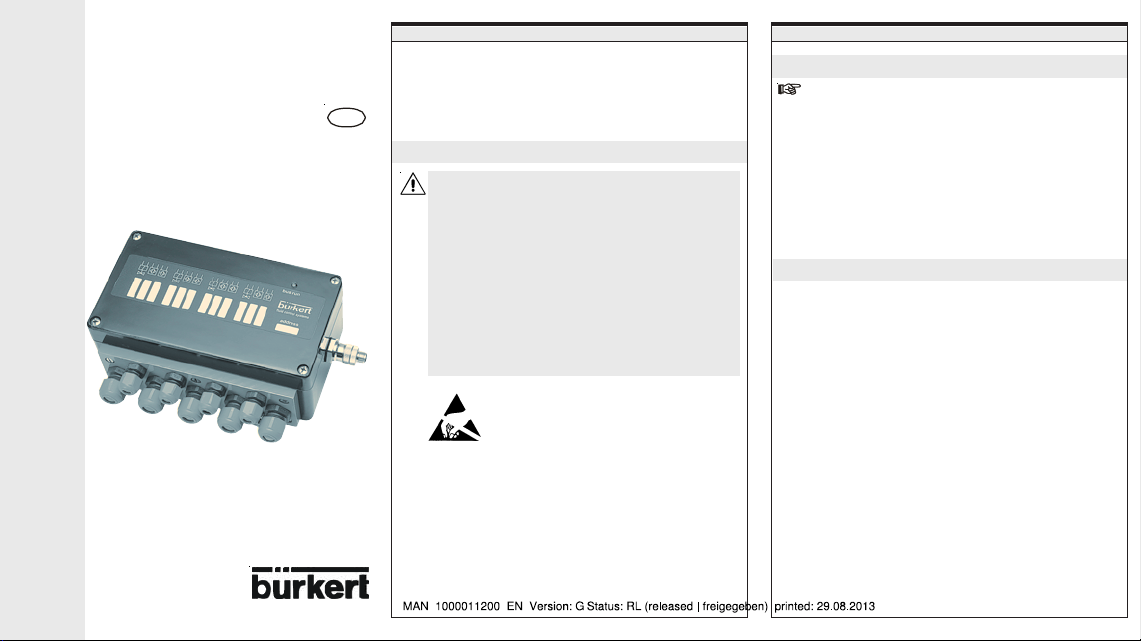
I/O-Box with PROFIBUS
a
d
d
l
e
e
r
g
m
m
n
b
t
n
n
n
c
t
PA Connection
Quickstart
Installation and Operation
GB
Fluid Control Systems
GENERAL INSTRUCTIONS
To ensure that the device functions correctly, and will have a long
service life, please comply with the information in these Operating
Instructions, as well as the application conditions and additional data
given in the data sheet. For more detailed information regarding the
commissioning of a PROFIBUS PA branch, we recommend the
"PROFIBUS PA Commissioning Handbook" of the PNO.
Safety Instructions
• When planning the application of the device, and during its
operation, observe the general technical rules!
• Work on the device should only be carried out by
specialist staff using suitable tools!
• Observe the valid accident prevention and safety
regulations for electrical equipment during the operation,
maintenance and repair of the equipment!
• Always switch off the voltage supply before working on
the system!
• Only use lines fitted with an earth line, and connect the
earth!
• Take suitable measures to prevent unintentional operation
or impermissible impairment!
ATTENTION!
CAUTION ON HANDLING!
COMPONENTS/MODULES LIABLE TO
ELECTROSTATIC DAMAGE!
The device contains electronic components that are sensitive to
electrostatic charging (ESD). These components are
endangered by contact with statically charged persons or
objects. In the worst case they are immediately destroyed or fail
after putting into operation.
Observe the requirements of EN 100 015-1 in order to minimize
or avoid the risk of damage by instantaneous electrostatic
discharge. Make sure also that you do not touch electronic
components when they are under supply voltage.
GENERAL INSTRUCTIONS TECHNIC
Use for the intended purpose
Please observe the notes in these operating instructions
together with the conditions of use and permitted data that are
specified on the rating plate in order that the device will
function perfectly and remain operable for a long time.
On nonobser-vance of these notes and unauthorized
interference with the device, we will refuse all liability and the
warranty on device and accessories will become void!
The device serves exclusively to drive process valves of
types 6520 and 6521 NAMUR. Any different use or use going
beyond this is considered improper use. Bürkert is not liable
for damage resulting from such use. The risk is carried solely
by the user.
General description
• For installation and operation in potentially explosive environments,
observe the relevant national regulations. (in Germany: VDE 0165)
• The device serves exclusively to drive process valves of types
6520 and 6521 NAMUR
- Driving of four type 6520/6521valves (PTB n° Ex-97.D.2089x)
- Connection of two sensors per valve (see table)
• The line resistance to the sensors and valves shall be not more than
20 Ohm for a max. cable length of 30 m.
• Use only shielded cable for connecting the sensors and valves.
Note also that the screening must be connected, e.g. at the front
panel of the housing.
The values of the capacity and inductance are specified in the
conformity certificate. Please observe the instructions of the
Conformity Certificate PTB Nr. EX-97.D.2089X for the supply of the
valve. More information regarding the operation and installation of
the type 6115 (6520) valve can be found in the operating
instructions for these valves.
• The Design Inspection Certificates are to be found in the
Instructions
on the CD.
Operating
Page 2
Technical data
Field bus interface according to IEC 1158-2
Communication device following the FISCO model
Electrical data
Permitted operating voltage 9 - 24 V
Permitted operating voltage,
intrinsically safe: referring to power
supply device with
– trapezoidal characteristic curve
– linear characteristic curve
Operating current 16.5 mA ± 6 %
Maximum current in case of a fault < 22.5 mA
max. permissible power of the
power supply with intrinsically safe
bus supply
Operating conditions
Permissible temperature range -25 to 60 °C
Climatic test
Insulation class 3
Protection class of housing
Explosion protection to
Conditions of the EMC law fulfilled
Resistance to interference EN 50052-2
Transmitted interference EN 50081-2
We reserve the right to make technical changes without notice!
9 - 15 V
9 - 17,5 V
2 W
DIN IEC Part 2 - 38
exposure 10 cycles à 24 h
IP 65
(when using corresponding screwed fittings)
EN 50020 and EN 50014
II 2 (1) G EEx ia IIC T6
INSTALLATION AND COMMISSIONING
Installation and Commissioning
Preferred fitting position: Attachment screws pointing
downwards!
If EMV screwed fittings are used, position the screens
according to manufacturer's instructions!
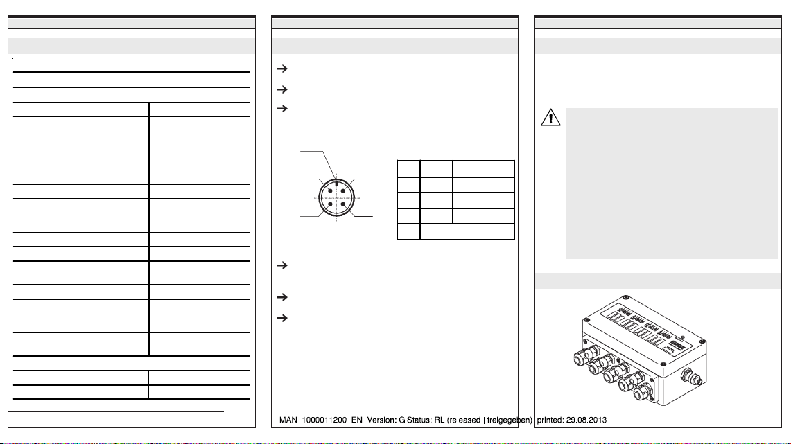
On using a Weidmüller plugged connector for PROFIBUS PA,
the following configuration applies:
Positioning dimensions
B
S
On the front panel threads to M20 and M16 are provided; on
the side a thread to M16.
The terminals may only be removed when not under voltage!
The front panel is designed for a maximum of 5 changes.
The fixing screws of the front panel may be tightened with a
maximum of 1.5 Nm.
View onto pin base and pins:
Pin Colour PROFIBUS PA
n.c.
AbluePA-
S black screen
A
BbrownPA+
n.c. not connected
INSTALLATION AND COMMISSIONING
Measures to be taken before installation
Check the connections, voltage and operating pressure!
Ensure that the max. operating data (see name plate) is not
exceeded!
This device complies with the European Community EMC
guideline No. 89/336/EWG.
Observe the installation instructions in order to fulfil the
regulations of this guideline. Connect the screw terminal
TE (technical earth) to the earth potential using a cable that
is as short as possible, or take suitable measures to
prevent undesired electro-magnetic interference affecting
the device.
Connecting cable for TE (technical earth):
- minimal diameter: 2.5 mm²
- maximum length: 30 cm
Electrical connection
Fig.: I/O-Box Type 8642 NAMUR with PROFIBUS PA circuit
Page 3

INSTALLATION AND COMMISSIONING
Terminal connections
Terminals A (exit) and
E (entry):
Connection for the
PROFIBUS-PA field
bus: any polarity can
be used between
terminal 1 and 2.
Max. permissible
torque for the bus
connections
(Weidmüller): 5 Nm.
INSTALLATION AND COMMISSIONING
Terminal connections
Bürkert piezo-valves type 6520 may be connected to the terminals
for actuators. Observe polarity. More detailed instructions for
connection and operation of the valves are to be found in the PTB
Test Certificate and in the Operating Manual for the valves.
Connection of the sensors to
the terminals:
Pola rit y - +
Terminals 152 151
Terminals 142 141
Terminals 252 251
Terminals 242 241
Terminals 352 351
Terminals 342 341
Terminals 452 451
Terminals 442 441
Two sensors are always allocated to a valve. The sensors report the
end position of a connected process valve. The inputs can also
report other process parameters independent of the valves (e.g.
scraper end positions).
Connection of the actuators
to the terminals:
Pola rit y + -
Terminals 148 147
Terminals 248 247
Terminals 348 347
Terminals 448 447
INSTALLATION AND COMMISSIONING
Setting the station addresses
DIP switch 1 to 7: Bit 1 to Bit 7
The DIP switches are only read in when the unit is switched
on.
In the PROFIBUS PA, each station is given an adress. These
addresses are set up using the DIP switches 1 to 7. The
permissible address range lies between 3 and 124.
Settings:
2021222324252
DIP-1 DIP-2 DIP-3 DIP-4 DIP-5 DIP-6 DIP-7 Address
ON ON OFF O FF OFF OFF OFF 3
OFF OFF ON ON ON ON ON 124
ON OFF ON ON ON ON ON 125
OFFONONONONONON126*
*Delivery state: Address 126
If switch 8 is in the ON position, the internal address is used!
This adress can be set up via the field bus.
6
:
LED display
The LED flashes when the device is engaged in cyclic data
communication. The LED lights briefly on connecting the device. If
the device detectes an internal error, the LED remains lit.
Page 4

BRANCHES
Contact addresses / Kontaktadressen
Germany / Deutschland / Allemange
Bürkert Fluid Control System
Sales Centre
Chr.-Bürkert-Str. 13-17
D-74653 Ingelfingen
Tel. + 49 (0) 7940 - 10 91 111
Fax + 49 (0) 7940 - 10 91 448
E-mail: info@de.buerkert.com
International
Contact addresses can be found on the internet at:
Die Kontaktadressen finden Sie im Internet unter:
Les adresses se trouvent sur internet sous :
www.burkert.com Bürkert / Company / Locations
Chr.-Bürkert-Straße 13-17 Berlin Ph: (0 30) 67 97 17 - 0
74653 Ingelfingen Dortmund Ph: (0 23 73) 96 81 - 0
Ph: (0 79 40) 10-111 Frankfurt Ph: (0 61 03) 94 14 - 0
Fax (0 79 40) 10-448 Hannover Ph: (05 11) 9 02 76 - 0
www.buerkert.com München Ph: (0 89) 82 92 28 - 0
info@de.buerkert.com Stuttgart Ph: (07 11) 4 51 10 - 0
BÜRKERT INTERNATIONAL
A Ph. (01) 894 13 33 F ax (01) 894 13 00
AUS Ph. (02) 1300 888 868 Fax (02) 1300 888 076
B Ph. (03) 325 89 00 F ax (03) 325 61 61
BRA Ph. (011) 51 82 00 11 F ax (011) 51 82 88 99
CDN Ph. (905) 847 55 66 Fax (905) 847 90 06
CH Ph. (041) 785 66 66 Fax (041) 785 66 33
CN Ph. (21) 58 68 21 19 Fax (21) 58 68 21 20
CZ Ph. (543) 25 25 05 Fax (543) 25 25 06
DK Ph. (44) 50 75 00 Fax (44) 50 75 75
E Ph. (93) 477 79 80 Fax (93) 477 79 81
EST Ph. (372)644 06 98 Fax (372)631 3 7 5 9
F Ph. (0388) 58 91 11 Fax (0388) 57 20 08
HKG Ph. 24 80 12 02 Fax 24 18 19 45
I Ph. (02) 95 90 71 Fa x (02) 95 90 72 51
IND Ph. (044)52 30 34 56 Fax (044)52 30 32 32
J Ph. (03) 53 05 36 10 Fax (03) 53 05 36 11
KOR Ph. (02) 34 62 55 92 Fax (02) 34 62 55 94
N Ph. (63) 84 44 10 Fax (63) 84 44 55
NL Ph. (0346) 58 10 10 Fax (0346) 56 37 17
NZ Ph. (09) 622 28 40 Fa x (09) 622 28 47
P Ph. (21)212 84 90 Fax (21)212 84 91
PL Ph. (022) 840 60 10 Fax (022) 840 60 11
RC Ph. (02) 26 53 78 68 Fax (02) 26 53 79 68
RP Ph. (02) 776 43 8 4 Fax (02)776 43 82
S Ph. (040) 664 51 00 Fax (040) 664 51 01
SA Ph. (011)574 60 00 Fax (011) 454 14 77
SF Ph. (09) 54 97 06 00 Fa x (09) 503 12 75
SIN Ph. 68 44 22 33 Fax 68 44 35 32
TR Ph. (0232) 459 53 95 Fax (0232) 459 76 94
TT Ph. (04)643 50 08 Fax (04)643 70 10
UK P h. (01453) 73 13 53 Fa x (01453) 73 13 43
USA Ph. (949) 223 31 00 Fax (949) 223 31 98
Operating Instructions 0510/04_EU-EN_00804398
CONFIGURATION CONFIGURATION
Memory allocation for the effective data traffic
Basis: handbook for your PLC
• In order to be able to carry out the correct settings of the
configuration program, copy the unit-specific file (buer6521.GSD)
from Bürkert into the directory that contains the configuration
software. For reading in and editing the configuration, please read
the documentation for your PLC or process control system.
• Further informations regarding memory allocation can be found in
the handbook.
Block parameters of the transducers Block p
Parameter Description
SELF_CALIB_CMD Initiat ion of a device-specific calibration
SENSOR_WIRE
_CHECK
procedure, manufacturer specific 0default.
------xy
y = 0 active undamped
y = 1 active damped
x = 0 sensor 1 indicates "valve open"
x = 1 sensor 1 indicates "valve
closed"
Enables the lead breakage and short circuit
detection.
List of valid values:
0 Lead breakage and short circuit
detection enable
1 Lead breakage detection enable,
short circuit detection disable
2 Lead breakage detection disable,
short circuit detection enable
3 Lead breakage and short circuit
detection disable
Page 5

CONFIGURA
READBACK_D: This parameter indicates the position of the valve
TION
and the sensors.
Bit76543210
not initialised
0 0
closed
0 1
open
1 0
moving
1 1
State sensor 1
Short circuit sensor 1
Lead break sensor 1
State sensor 2
Short circuit sensor 2
Lead break sensor 2
1 = activ
0 = inactiv
SP_D: Setpoint
Bit 0 in the value indicates the valve position. The status
transferred must be a "good" status, e.g. 0x80
SENSORSION
Manufacturer Pepperl+Fuchs
Sensor type: single, proximity
Id. no. Description
32571 NCB1.5-6.5M25-NO
38181 NCB1.5-6.5M25-NO-V1
32570 NCB1.5-8GM25-NO
39848 NCB1.5-8GM25-NO 1OM
39847 NCB1.5-8GM25-NO 5M
33876 NCB1.5-8GM25-NO-V1
27419 NCB2-12GM35-NO
39850 NCB2-12GM35-NO 1OM
39849 NCB2-12GM35-NO 5M
33877 NCB2-12GM35-NO-V1
29627 NCB2-F1-NO
27426 NCB5-18GM4O-NO
39854 NCB5-18GM4O-NO 1OM
39853 NCB5-18GM4O-NO 5M
33879 NCB5-18GM4O-NO-V1
27422 NC N4-12GM35-NO
39852 NCN4-12GM35-NO 1OM
39851 NCN4-12GM35-NO 5M
33878 NCN4-12GM 35-NO-V1
27427 NC N8-18GM4O-NO
39855 NCN8-18GM4O-NO 5M
33880 NCN8-18GM 4O-NO-V1
11498 NJ 0.8-4.5-N
11497 NJ 0.8-5GM-N
40165 NJ 0.8-5GM-N 5M
35986 NJ 0.8-5GM-N 10M
1828 NJ 1.5-6.5-N
35706 NJ 1.5-6.5-N 15M
2497 NJ 1.5-6.5-N 5M
1830 NJ 1.5-8GM-N
35270 NJ 1.5-8GM-N 10M
5129 NJ 1.5-8GM-N 5M
SENSORS SENSORS
Manufacturer Pepperl+Fuchs
Sensor type: single, proximity
Id. no. Descr iption
17547 NJ 1.5-8GM-N-V1
5000 NJ 2-11-SN
31194 NJ 2-11-SN
31195 NJ 2-11-SN-G
43566 NJ 2-11-SN-G 1 0M
36164 NJ 2-11-SN-G 10M
43565 NJ 2-11-SN-G 5M
14622 NJ 2-12GM-N
23801 NJ 2-12GM-N 1 0M
35578 NJ 2-12GM-N 21M
14623 NJ 2-12GM-N 5M
18306 NJ 2-12GM-N-V1
7893 NJ 2-12GK-N
36906 NJ 2-12GK-N 5M
17905 NJ 2-V3-N
15658 NJ 2-V3-N-V5
28408 NJ 3-18GK-S1N
7830 NJ 5-11-N
9329 NJ 5-11-N 15 M KA.
1539 NJ 5-11-N 5M KA.
7831 NJ 5-11-N-G
28419 NJ 5-11-N-G 10M KA.
1653 NJ 5-11-N-G 5M KA.
35273 NJ 5-11-N-G 6M
14848 NJ 5-30GK-S1N
31606 NJ 5-30GK-S1N 10M
36241 NJ 5-30GK-S1N 5M
5200 NJ 6-22-SN
35784 NJ 6-22-SN 10M
5204 NJ 6-22-SN-G
37686 NJ 6-22-SN-G 10M
35964 NJ 6-22-SN-G 3M
Page 6

SENSORS SENSORS SENSORS
Andere Hersteller
Manufacturer Pepperl+Fuchs
Sensor type: double, proximity
Id. no. Description
85169 NCN3-F24L-N4
85168 NCN3-F24R-N4
38142 NCN3-F25F-N4-V1
37852 NCN3-F25-N4-014
41943 NCN3-F25-N4-075
38139 NCN3-F25-N4-V1
47571 NCN3-F31-N4-K
48105 NCN3-F31-N4-K-K
NCN3-F31-N4-K-V1
NCN3-F31-N4-K-V1
NCN3-F31-N4-K-V16
NCN3-F31-N4-K-V16
NCN3-F31-N4-V16- K
NCN3-F31-N4-V16- V1
43736 NCN3-F31-N4-V16-V16
48258 NCN3-F31-N4-V18
Manufacturer Pepperl+Fuchs
Sensor type: single, slit
Id. no. Description
37316 SC2-N0
35372 SC3.5-N0
47942 SC3.5-N0
35376 SC3.5-N0 BLUE
35373 SC3.5-N0 YELLOW
35375 SC3.5-N0 GREEN
35374 SC3.5-N0 WHITE
8698 SJ 2-N
36195 SJ 2-N 5M KA
22146 SJ 2-SN
31192 SJ 2-SN
32583 SJ 2-SN
36643 SJ 2-SN XM KA
35400 SJ 3.5-G-N
1657 SJ 3.5-N
1654 SJ 3.5-N BLUE
Other manufacturers
Manufacturer: Turck
Description Sensor type
BIM-AKT-Y1X single, proximity
Si 3.5-K10-Y1 singl e, slit
Manufacturer: Ifm
Description Sensor type
NN5022 double, inductive
proximity switch
 Loading...