

Page 1
Type 8635
SIDE Control Positioner
Operating Instructions
Page 2

We reserve the right to make technical changes without notice.
Technische Änderungen vorbehalten.
Sous réserve de modifications techniques.
© 2003 – 2011 Bürkert Werke GmbH
Op e ra ti ng I n st ru ct io ns 1111/06 _E U- EN _00 8 04 60 8 / Or ig in al DE
Page 3

C
ONTENTS
Operating Instructions for
SIDE Control Positioner Type 8635
(S/HART, PROFIBUS PA,
HART-Hand Terminal)
GENERAL NOTES
Symbols....................................................................................................................................................................................................................................................... 10
General safety notes
................................................................................................................................................................................................................. 10
Protection from damage by electrostatic charging ...................................................................................................................... 11
Device-related notes ................................................................................................................................................................................................................ 11
Scope of delivery ........................................................................................................................................................................................................................... 11
Warranty conditions ................................................................................................................................................................................................................... 12
Master code
SYSTEM DESCRIPTION
Construction of SIDE Control
Illustration............................................................................................................................................................................................................................................14
Features
(S/HART)
..........................................................................................................................................................................................................
(S/HART)
(S/HART)
............................................................................................................................................................................................................................................... 15
.................................................................................................................................................... 14
12
Functional diagram of the SIDE Control
valve with single-acting diaphragm actuator.......................................................................................................................................... 16
Operation as a positioner
Characteristics of the positioner software ................................................................................................................................................18
Schematic illustration of position control
Operation as a process controller
Characteristics of the process controller software (option)...............................................................................................20
Schematic illustration of process control
(S/HART)
(S/HART, option)
(S/HART)
................................................................................................................................................................
.................................................................................................................................................... 19
................................................................................................................................................... 22
in connection with a control
................................................................................................................
17
20
8635 - 1
Page 4

C
ONTENTS
Interfaces
Technical data of the SIDE Control
Technical data
Factory settings
SYSTEM DESCRIPTION
Construction of Side Control PA
(S/HART)
(S/HART)
(S/HART)
.................................................................................................................................................................................................................. 23
(S/HART)
................................................................................................................................................................................................
...........................................................................................................................................................................................
..................................................................................................................................
(PROFIBUS PA)
(PROFIBUS PA)
...................................................................................................................... 28
Illustration............................................................................................................................................................................................................................................ 28
Design features
Options
................................................................................................................................................................................................................................................... 29
Functional diagram of SIDE Control
.......................................................................................................................................................................................................................... 29
(PROFIBUS PA)
in connection with a control
valve with single-acting diaphragm actuator.......................................................................................................................................... 30
Operating as a positioner
(PROFIBUS PA)
........................................................................................................................................... 31
24
24
26
Characteristics of the positioner software................................................................................................................................................32
Schematic illustration of position control
Interfaces
Technical data of SIDE Control
Technical data
Factory settings
(PROFIBUS PA)
(PROFIBUS PA)
(PROFIBUS PA)
.............................................................................................................................................................................................
(PROFIBUS PA)
........................................................................................................................................................................... 35
.................................................................................................................................................... 33
.........................................................................................................................
......................................................................................................................................................................
INSTALLATION
Attachment and assembly................................................................................................................................................................................................ 38
Complete system with Bürkert continuous valve from series 27xx........................................................................ 38
Attachment to a continuous valve with linear actuator acc. to NAMUR
Attachment to a continuous valve with part-turn actuator
.................................................................................................... 42
Fluidic connection ........................................................................................................................................................................................................................ 44
........................................................... 39
34
35
36
Electrical connection
Electrical connection
2 - 8635
(S/HART)
..............................................................................................................................................................................
(PROFIBUS PA)
.........................................................................................................................................................
45
46
Page 5

C
ONTENTS
INDUCTIVE PROXIMITY SWITCHES
(S/HART, PROFIBUS PA, OPTION)
Description of the inductive proximity switches............................................................................................................................... 48
Configuration of the adjusting wheels
(option)
.................................................................................................................................
Settings......................................................................................................................................................................................................................................................... 49
Setting with one inductive proximity switch ............................................................................................................................................ 49
Setting with two inductive proximity switches
..................................................................................................................................... 49
Definition of the end positions with part-turn actuators ........................................................................................................ 49
OPERATING AND CONTROLLER FUNCTIONS
Operating and display elements............................................................................................................................................................................. 52
Operating levels
.............................................................................................................................................................................................................................. 52
48
Commissioning and set-up as a positioner
............................................................................................................................................ 53
Procedure for specifying the basic settings ........................................................................................................................................... 53
Main menu for settings on commissioning
Description of the procedure
...................................................................................................................................................................................... 55
............................................................................................................................................... 55
Configuring the supplementary functions ................................................................................................................................................. 59
Keys in the configuration level.................................................................................................................................................................................. 59
Configuration menu
Supplementary functions
................................................................................................................................................................................................................ 59
................................................................................................................................................................................................ 62
Operating the process ............................................................................................................................................................................................................ 85
Changing between operating modes ............................................................................................................................................................... 85
Operating mode AUTOMATIC
Meaning of the keys in the operating mode AUTOMATIC .................................................................................................... 86
Displays in the operating mode AUTOMATIC
(S/HART)
..................................................................................................................................................
...................................................................................................................................... 86
86
Operating mode AUTOMATIC
(PROFIBUS PA)
.............................................................................................................................
87
Meaning of the keys in the operating mode AUTOMATIC .................................................................................................. 87
Displays in the operating mode AUTOMATIC
...................................................................................................................................... 87
Operating mode MANUAL............................................................................................................................................................................................... 88
Meaning of the keys in the operating mode MANUAL ............................................................................................................. 88
Displays in the operating mode MANUAL
................................................................................................................................................ 88
8635 - 3
Page 6

C
ONTENTS
OPERATING THE PROCESS CONTROLLER
(S/HART)
Factory settings of the process controller.................................................................................................................................................. 90
Setting up a process control system
Self-parametrization for controllers -
Supplementary function
Basic settings of the function
P.Q’LIN
P.CO TUNE
- starting the routine for linearization of the process characteristic .......................................... 99
Displays during call-up and execution of the routine ..................................................................................................................99
- self-optimization of the process controller (process tune)................................................100
Operation......................................................................................................................................................................................................................................... 101
P.CONTRL
P.CONTRL
................................................................................................................................................................. 90
X.TUNE
.................................................................................................................................................................
...................................................................................................................................
.................................................................................................................................................
Operating the process ........................................................................................................................................................................................................ 104
91
91
92
Changing between operating modes ........................................................................................................................................................... 104
Operating mode AUTOMATIC ................................................................................................................................................................................ 105
Meaning of the keys in operating mode AUTOMATIC ........................................................................................................... 105
Displays in operating mode AUTOMATIC
............................................................................................................................................. 105
Manual changing of the process setpoint ............................................................................................................................................. 106
Operating mode MANUAL........................................................................................................................................................................................... 107
Meaning of the keys in operating mode MANUAL .................................................................................................................... 107
Displays in operating mode MANUAL
CONFIGURATION FOR BUS COMMUNICATION
........................................................................................................................................................ 107
(PROFIBUS PA)
GSD file.................................................................................................................................................................................................................................................... 110
Setting the device address.......................................................................................................................................................................................... 113
Cyclic parameters ............................................................................................................................................................................................................... 113
Configuration parameters
4 - 8635
........................................................................................................................................................................................... 114
Page 7

C
ONTENTS
OPERATING VIA THE HART HAND TERMINAL
(HART)
General ..................................................................................................................................................................................................................................................... 120
System description
Illustration of the system ............................................................................................................................................................................................. 121
Menu description and key assignment
Data entry
....................................................................................................................................................................................................................................... 122
.................................................................................................................................................................................................................. 121
..................................................................................................................................................... 121
Commissioning............................................................................................................................................................................................................................. 123
Preparation.................................................................................................................................................................................................................................... 123
AUTOTUNE
procedure (required on first commissioning) ............................................................................................ 123
Operating the positioners via the HART hand terminal................................................................................................... 125
Configuration .............................................................................................................................................................................................................................. 125
Display of the process variables
Changing the process variables
...................................................................................................................................................................... 125
........................................................................................................................................................................ 126
Operating the process controller via the HART hand terminal.............................................................................127
Configuration .............................................................................................................................................................................................................................. 127
Display of the process variables
Changing the process variables
...................................................................................................................................................................... 130
........................................................................................................................................................................ 130
Memory organization ........................................................................................................................................................................................................... 132
MAINTENANCE AND ERROR ELIMINATION ON THE POSITIONER
Maintenance ...................................................................................................................................................................................................................................... 134
Error messages and malfunctions .................................................................................................................................................................... 134
Error messages on the LC display
Other malfunctions
............................................................................................................................................................................................................. 135
................................................................................................................................................................ 134
MAINTENANCE AND ERROR ELIMINATION ON THE PROCESS
CONTROLLER
(S/HART)
Maintenance ...................................................................................................................................................................................................................................... 138
Error messages and malfunctions .................................................................................................................................................................... 138
Error messages on the LC display
Other malfunctions
............................................................................................................................................................................................................. 139
................................................................................................................................................................ 138
8635 - 5
Page 8

C
ONTENTS
Appendix
GENERAL RULES
Selection criteria for continuous valves.................................................................................................................................................... 142
Characteristics of PID controllers....................................................................................................................................................................... 144
P fraction
I fraction
D fraction
Superposition of P, I and D fractions
Realized PID controller
.......................................................................................................................................................................................................................................... 144
............................................................................................................................................................................................................................................ 145
......................................................................................................................................................................................................................................... 146
............................................................................................................................................................ 147
................................................................................................................................................................................................. 148
Setting rules for PID controllers ............................................................................................................................................................................ 149
Setting rules after Ziegler and Nichols (oscillation method)
Setting rules after Chien, Hrones and Reswick (output step method)
........................................................................................... 149
............................................................. 150
OPERATING STRUCTURE
Operating structure of the SIDE Control
Operating structure of the SIDE Control
Operating structure of the HART hand terminal
(S/HART)
................................................................................................................ 154
(PROFIBUS PA)
(HART)
........................................................................................... 159
............................................................................................... 160
TABLE FOR POSITIONER............................................................................................................................................................................ 165
TABLES FOR PROCESS CONTROLLER
MASTER CODE (
6 - 8635
S/HART)
............................................................................................................................................................................. 169
(S/HART)
......................................................................... 167
Page 9
C
ONTENTS
APPROVALS
Declaration of Conformity for Positioner Type 8635 SIDE Control S/HART .................................... 174
EC Design Inspection Certificate for Positioner Type 8635 SIDE Control S/HART .............175
APPROVALS
Declaration of Conformity for Positioner Type 8635 SIDE Control PA ....................................................... 180
EC Design Inspection Certificate for Positioner Type 8635 SIDE Control PA ............................... 181
1st Supplement ....................................................................................................................................................................................................................... 184
APPROVALS
EC Design Inspection Certificate (ATEX) for slot initiators Types SJ ... and SC .................... 186
(S/HART)
(PROFIBUS PA)
(S/HART, PROFIBUS PA)
Inductive proximity switch NAMUR
.............................................................................................................................................................. 189
8635 - 7
Page 10

C
ONTENTS
8 - 8635
Page 11

GENERAL NOTES
GENERAL NOTES
Symbols......................................................................................................................................................................................................................................................... 10
General safety notes
Protection from damage by electrostatic charging ........................................................................................................................ 11
Device-related notes .................................................................................................................................................................................................................. 11
Scope of delivery
Warranty conditions
Master code
(S/HART)
................................................................................................................................................................................................................... 10
............................................................................................................................................................................................................................. 11
..................................................................................................................................................................................................................... 12
............................................................................................................................................................................................................
12
8635 - 9
Page 12
GENERAL NOTES
Symbols
The following symbols are used in these operating instructions:
marks a work step that you must carry out.
ATTENTION!
NOTE
(S/HART)
(PROFIBUS PA)
(HART)
marks notes on whose non-observance your health or the functioning of the device
will be endangered.
marks important additional information, tips and recommendations.
indicate chapters or sections of the text which are valid only for certain versions of the
SIDE Control.
General safety notes
Please observe the notes in these operating instructions together with the conditions of use and permitted
data that are specified in the data sheets of the electropneumatic positioner, in order that the device will
function perfectly and remain operable for a long time:
• This device left the manufacturer's factory in a faultless condition with regard to technical safety and
was tested. Proper transport, storage and installation are the prerequisites for continued correct
functioning.
• Keep to standard engineering rules in planning the use of and operating the device!
• Installation and intervention for maintenance work are only allowed by qualified personnel using suitable
tools!
• Observe the current regulations on accident prevention and safety for electrical devices during
operation and maintenance of the device!
• Take suitable precautions to prevent inadvertent operation or damage by unauthorized action!
• On non-observance of these notes and unauthorized interference with the device, we will refuse all
liability and the warranty on device and accessories will become void!
10 - 8635
Page 13
GENERAL NOTES
Protection from damage by electrostatic charging
This device contains electronic components that are sensitive to
electrostatic discharge (ESD). Contact to electrostatically charged persons
or objects will endanger these components. In the worst case, they will be
immediately destroyed or will fail after commissioning.
ATTENTION
EXERCISE CAUTION ON HANDLING!
ELECTROSTATICALLY SENSITIVE
COMPONENTS / MODULES
Device-related notes
• For installation and operation in potentially hazardous (explosive) locations, observe the regulations.
These are to be found in EN 60079-14 (IEC 60079-14).
• On electrical connection of the inherently safe circuits, observe the data in the relevant certificate of
conformity.
• Take suitable precautions to prevent electrostatic charging of plastic parts of the housing
(see EN 100015-1 / IEC 61340-5-1).
• No components shall be connected to the inputs and outputs of the boards whose electrical data lie
outside the limits determined for inherently safe operation and stated on the data sheet for the
positioner.
• In potentially explosive locations, only inherently safe devices (of EN 50020 / IEC 60079-11) shall
be connected to the serial interface.
• The plastic covering shall be removed only by the manufacturer!
• Interventions in the device with the housing open shall not be carried out in very humid or aggressive
atmospheres. Take precautions to prevent inadvertent mechanical damage to the boards or their
components. Limit the duration of opening of the housing to that which is absolutely necessary.
Observe the requirements of EN 100015-1 (IEC 61340-5-1) in order to
minimize the possibility of, or avoid, damage from instantaneous
electrostatic discharge. Also take care not to touch components that are
under supply voltage.
Scope of delivery
Immediately after receipt of a shipment, make sure that the contents are undamaged and match the
scope of delivery stated on the packing slip. In general this consists of:
• SIDE Control
• Operating Instructions for the SIDE Control
Add-on kits for linear and part-turn actuators may be obtained as accessories.
If there are discrepancies, please contact immediately our customer service:
Bürkert Fluid Control System
Bürkert Fluid Control Systems / Service Department
Sales Center
Chr.-Bürkert-Str. 13-17
Christian-Bürkert-Str. 13-17
D-76453 Ingelfingen
D-74653 Ingelfingen
Tel. + 49 (0) 7940 - 10 91 111
Tel.: (+49 7940) 10-111 Fax: (+49 7940) 10-448
Fax + 49 (0) 7940 - 10 91 448
E-Mail: info@de.buerkert.com
E-mail: info@de.buerkert.com
8635 - 11
Page 14
GENERAL NOTES
Warranty conditions
Warranty
The warranty is only valid if the device is used as intended in accordance with the specified application conditions.
This document contains no SURPLVHRIJXDUDQWHH . 3OHDVH refer to our general WHUPVRIsales andGHOLYHU\.
The warranty is only valid if the device is used as authorized in accordance with the
specified application conditions.
ATTENTION!
Master code
Operation of the SIDE Control
of this, there exists an unchangeable master code with which you can execute all operative actions on
the device. This 4-digit master code is to be found in the Appendix of these operating instructions in the
Chapter
The warranty covers only faultless condition of the SIDE Control. No liability will be
accepted for consequential damage of any kind that may arise from failure or
malfunctioning of the device.
(S/HART)
Master code (S/HART)
(S/HART)
.
can be blocked with a freely selectable user code. Independent
If required, cut out this code and keep it separate from these operating instructions.
12 - 8635
Page 15

SYSTEM DESCRIPTION (S/HART)
SYSTEM DESCRIPTION
(S/HART)
Construction of SIDE Control
Illustration.............................................................................................................................................................................................................................................. 14
Features
Functional diagram of the SIDE Control
valve with single-acting diaphragm actuator ............................................................................................................................................ 16
.................................................................................................................................................................................................................................................. 15
Operation as a positioner
Characteristics of the positioner software ................................................................................................................................................... 18
Schematic illustration of position control
Operation as a process controller
Characteristics of the process controller software (option) .................................................................................................. 20
Schematic illustration of process control
Interfaces
(S/HART)
.................................................................................................................................................................................................................. 23
Technical data of the SIDE Control
(S/HART)
(S/HART)
(S/HART, option)
...................................................................................................................................................... 14
(S/HART)
...................................................................................................................................................................
....................................................................................................................................................... 19
..................................................................................................................................................... 22
(S/HART)
in connection with a control
................................................................................................................
...................................................................................................................................
17
20
24
Technical data
Factory settings
(S/HART)
(S/HART)
..................................................................................................................................................................................................
..............................................................................................................................................................................................
8635 - 13
24
26
Page 16
SYSTEM DESCRIPTION (S/HART)
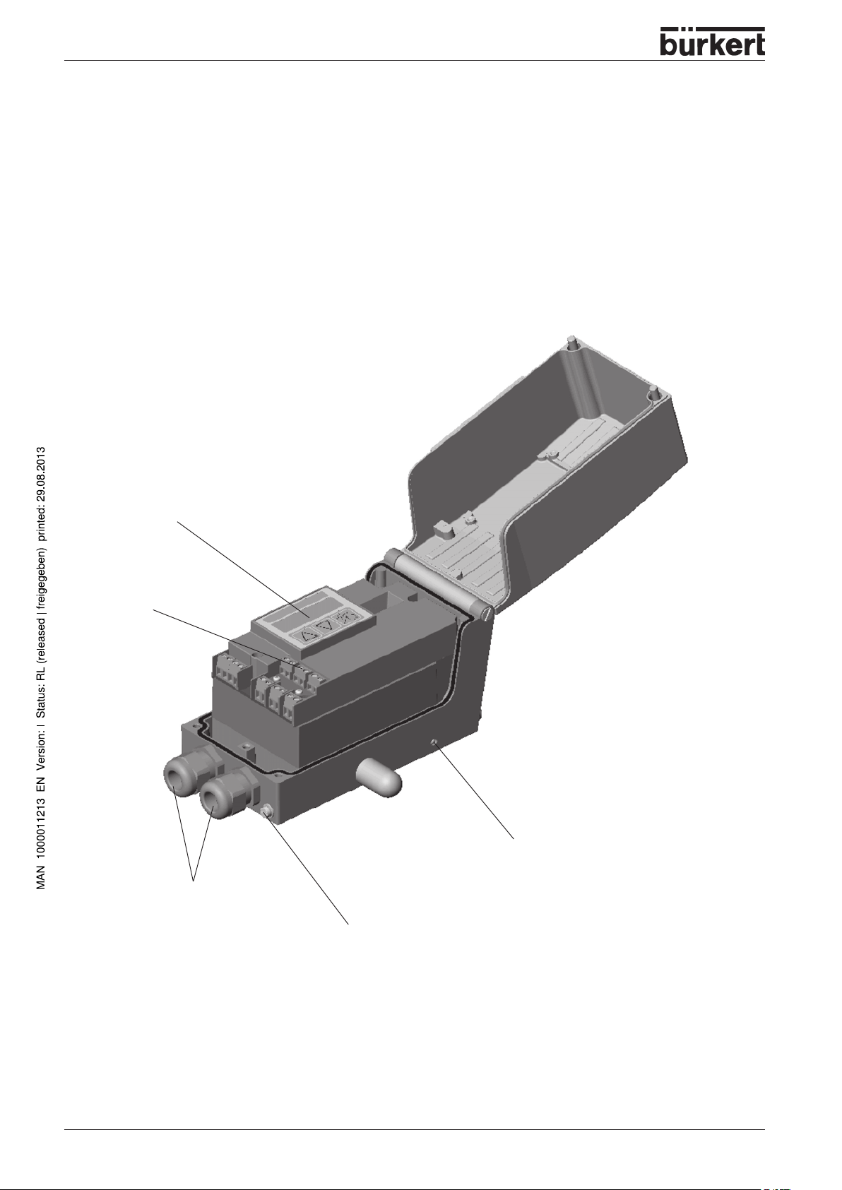
Construction of SIDE Control
The SIDE Control
single-acting linear or part-turn actuators.
The SIDE Control
communication to the HART protocol.
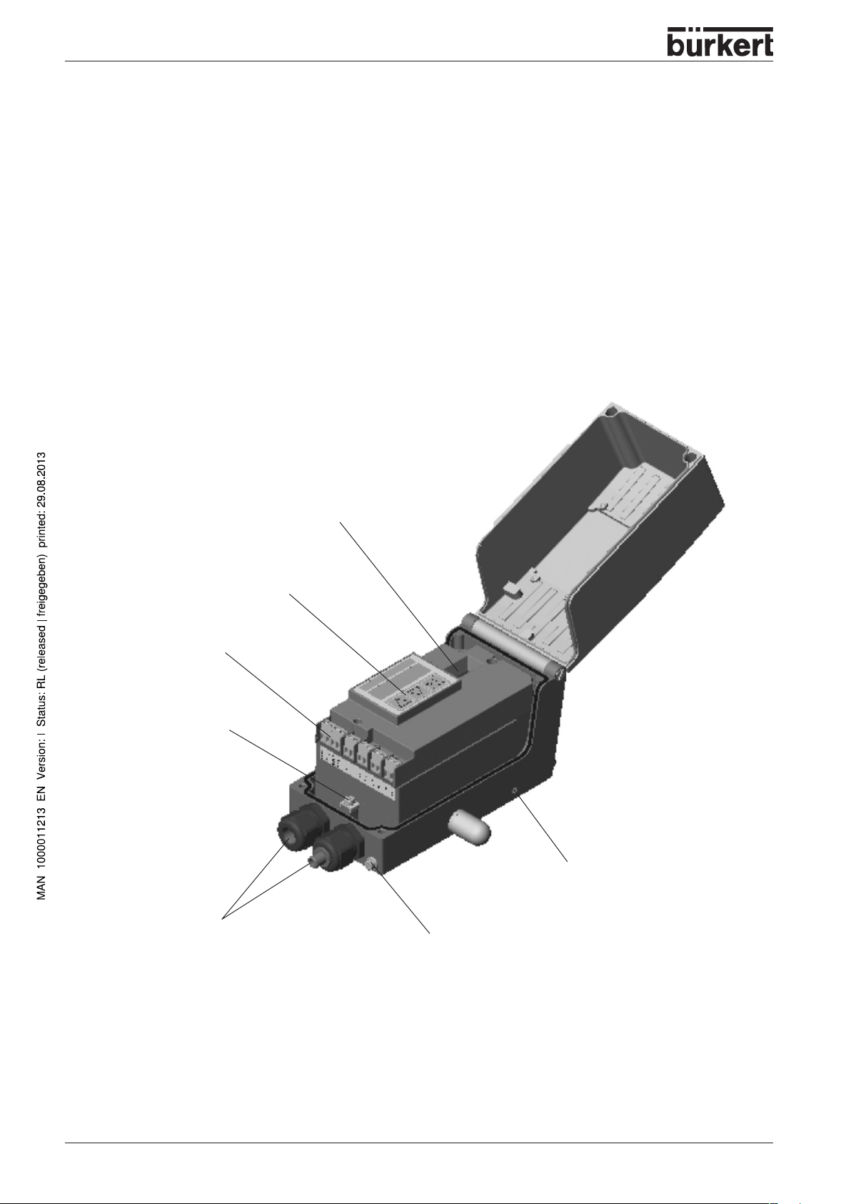
Illustration
Display with 3 operating keys
(S/HART)
(S/HART)
is a digital positioner for pneumatically operated continuous valves with
can be operated via a keypad with display. An optional extra is
(S/HART)
Screw terminals
Bushings M20x1.5
Throttle screw
Earthing (grounding) screw
14 - 8635
Page 17

SYSTEM DESCRIPTION (S/HART)
Features
•
Position sensor
Very high resolution conductive plastic potentiometer
• Microprocessor controlled electronics
for signal processing, control and driving the piezoelectric positioning system; setpoint entry and
power supply are via a 4 ... 20 mA standard signal.
•
Operating elements
The device can be set (configuration and parametrization) locally via three inside keys. An inside, 8digit, 16-segment LC display is provided, which can also show the setpoint or actual value.
Positioning system
•
A piezoelectric positioning system serves to drive the valve actuator.
•
Position repeater
via 2 inductive proximity switches (initiators)
•
Electrical interfaces
Cable bushing (M20x1.5) with screw terminals
Pneumatic interfaces
•
G1/4’’ interior thread
(option)
•
Housing
Aluminium housing (hard anodized and plastic-coated) with swing-up cover and captive screws.
•
Attachment
to linear actuators to NAMUR recommendation (DIN IEC 534 T6) or to part-turn actuators to
VDI/VDE 3845.
Option: integral attachment to Bürkert continuous valves
8635 - 15
Page 18
SYSTEM DESCRIPTION (S/HART)
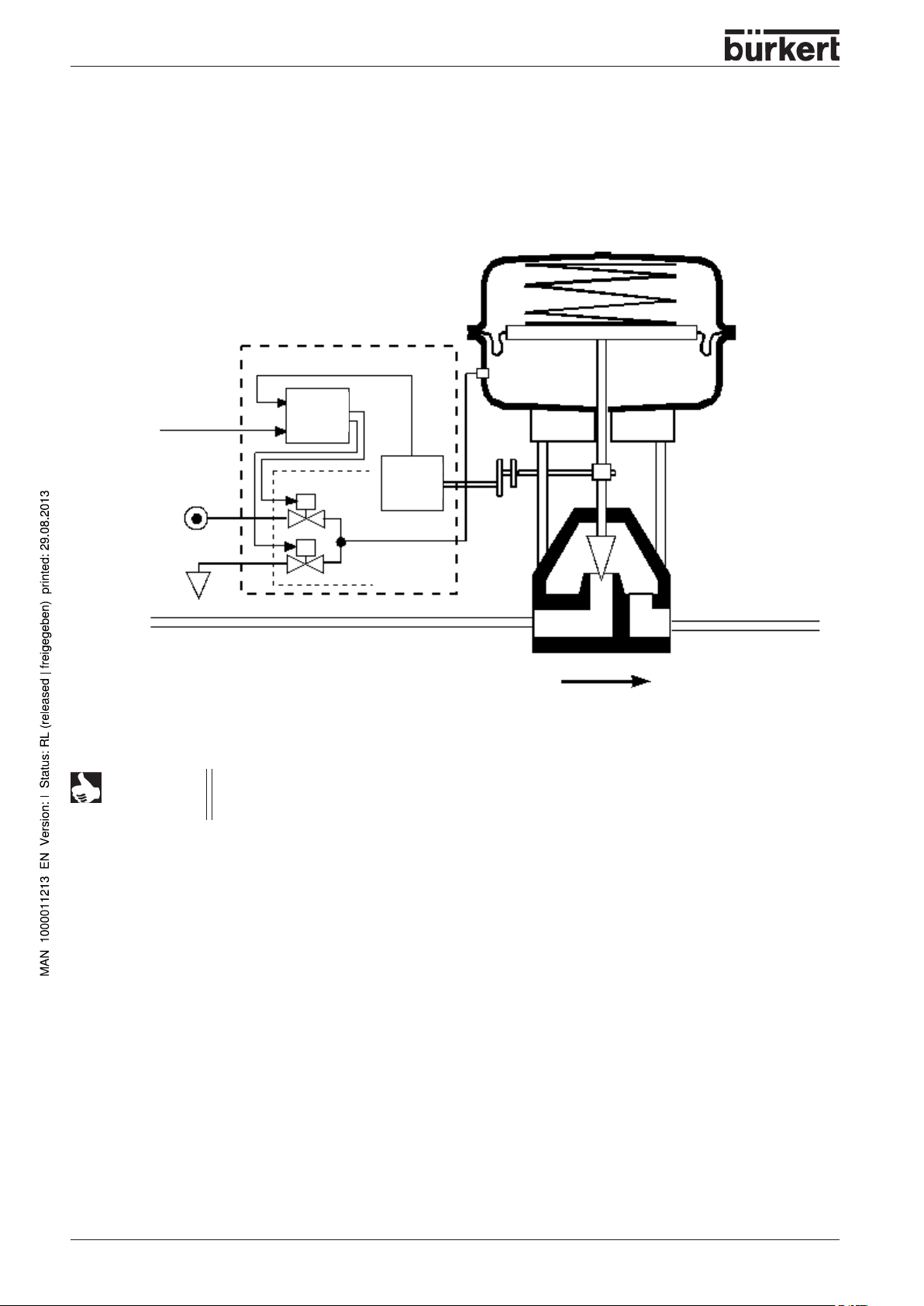
Functional diagram of the SIDE Control
(S/HART)
connected to a
control valve with single-acting diaphragm actuator
SIDE Control
(S/HART)
Actual position
External
position
setpoint
Pressure
supply
Positioner
Positioning system
pressurize
exhaust
Position
sensor
Lever
mechanism
Pneumatic actuator
(single-acting)
Valve (actuator)
NOTE
Exhaust air
In the case of integral attachment of the SIDE Control
(S/HART)
to a Bürkert
continuous valve, the position sensor is situated outside the SIDE Control
on the actuator and is connected to the latter with a cable.
(S/HART)
16 - 8635
Page 19
SYSTEM DESCRIPTION (S/HART)
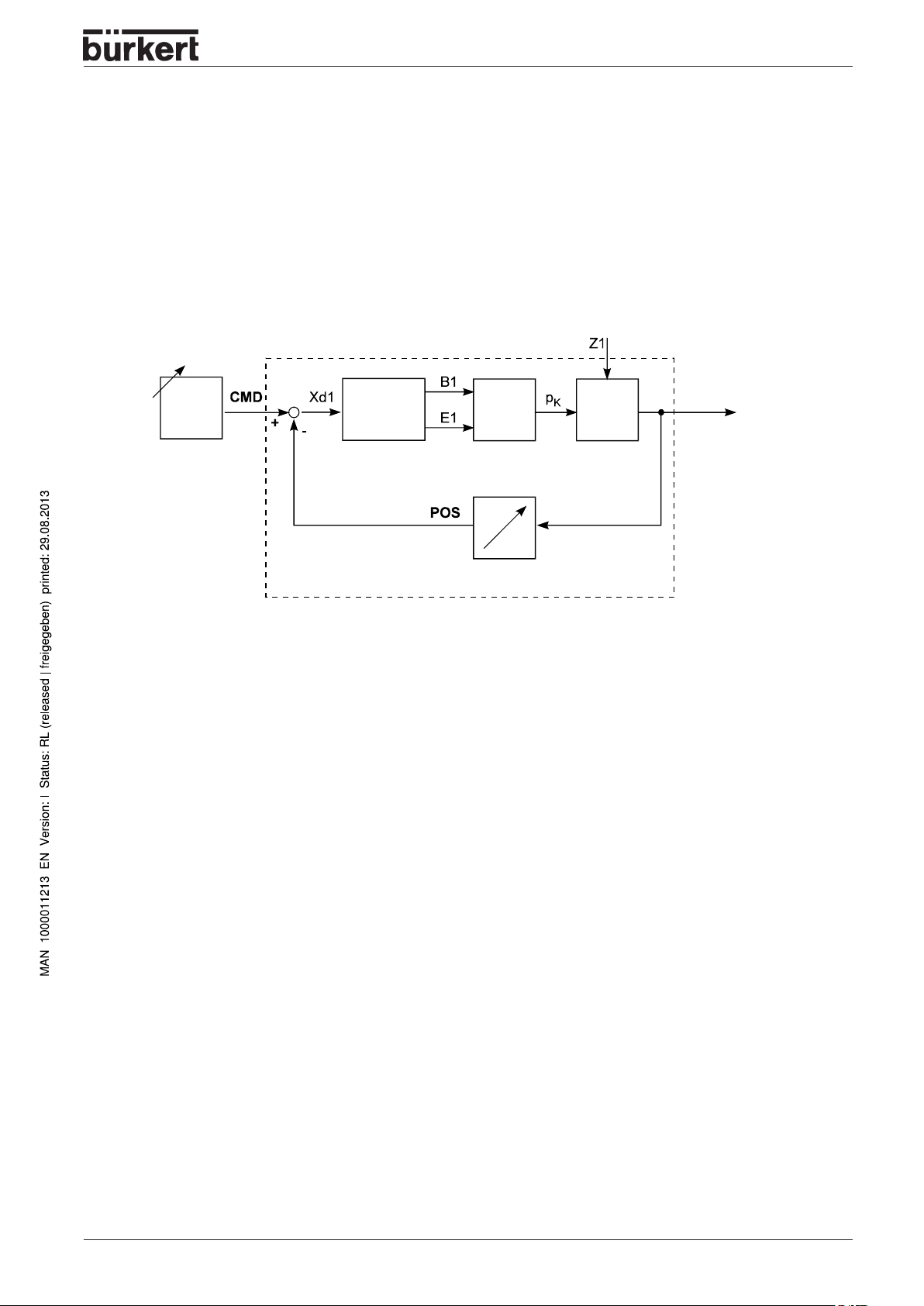
Operation as a positioner
The SIDE Control
measures the actual position (POS) of the actuator. The controller compares this actual value of the
position with the setpoint (CMD), which is presented as a standard signal. If a control difference (Xd1)
exists, a pulse-width modulated voltage signal is sent to the positioning system as the correcting variable. If the difference is positive, the pressurizing piezoelectric valve is driven via output B1; if it is negative,
the exhausting piezoelectric valve is driven via output E1. In this way, the position of the actuator is
altered until the control difference is 0. Z1 represents a disturbance.
Position
setpoint
(S/HART
controls the position of the pneumatic actuator, whereby the position sensor
Position control loop
(S/HART)
Positioner
Positioning system
(piezoelectric valves)
Position sensor
Valve opening
Continuous
valve
8635 - 17
Page 20
SYSTEM DESCRIPTION (S/HART)
Characteristics of the positioner software
Supplementary function Effect
Positioner with supplementary functions
AUTOT UNE
Tight-closing function
Stroke limitation
Limitation of correcting speed
Signal range splitting
Correction charakteristic for
adaptation to the operating curve
Insensitivity range
Direction of action of the controller
setpoint
Direction of action of the actuator Reserve of direction of action of the actuator.
Automatic adaptation of positioner to the control valve
in use.
Valve closes tight outside the control range. A value is
specified (in %) from which the actuator is completely
exhausted (at 0%) or pressurized (at 100%).
Mech. valve piston movement only within a defined
stroke range.
Actuator takes a preset time to move from OPEN to
CLOSED or from CLOSED to OPEN.
Splitting of the standard signal range over 2 or more
SIDE Controls.
Linearization of the process curve can be carried out.
The positioner responds only above a control difference
to be specified.
Reserve of direction of action of the setpoint.
Safety position Valve moves to a defined safety position
Code protection Blocking of the keypad or menu
Factory reset Reset to factory settings
Repeater (option)
Analog feedback of position Feedback of the values POS and CMD
Binary outputs
Hierarchic operating concept for simple operation with the following levels
Process operation
Configuration
Communication via HART protocol (option)
Feedback of various controller conditions (e.g. sensor
breakage or controller in safety position).
In this level, you switch between Automatic and Manual
operation.
In this level, you specify on commissioning certain
basic functions and configure supplementary functions
as required.
HART Hand Terminal Operation of the SIDE Control via a HART Hand Terminal
18 - 8635
Page 21
SYSTEM DESCRIPTION (S/HART)
D
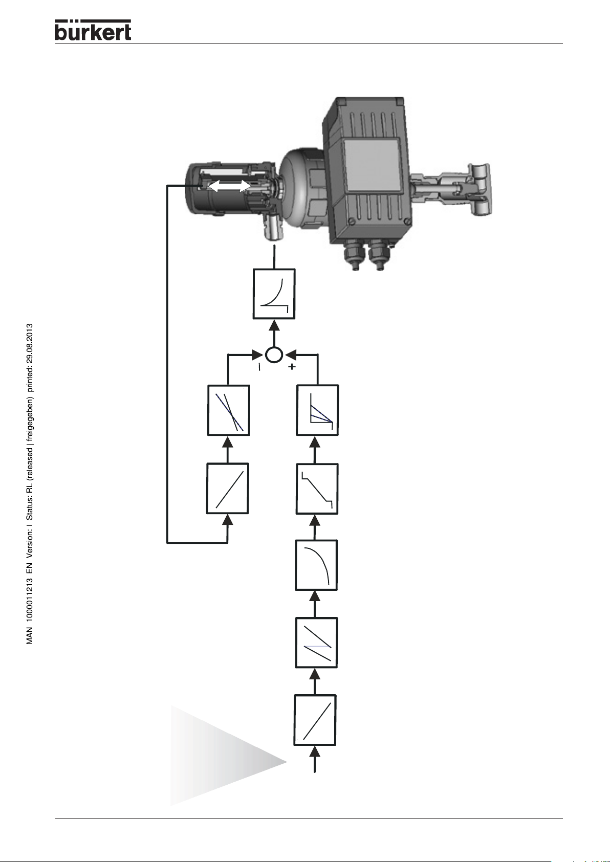
POS
POS
CM
INP
X.CONTRL
DBDx
CMD
X.LIMIT
DIR.ACT
X.TIME
Schematic illustration of position control
DIR.CMD SPLTRNG CHARACT CUTOFF
4 … 20 mA
INP
8635 - 19
Page 22
SYSTEM DESCRIPTION (S/HART)
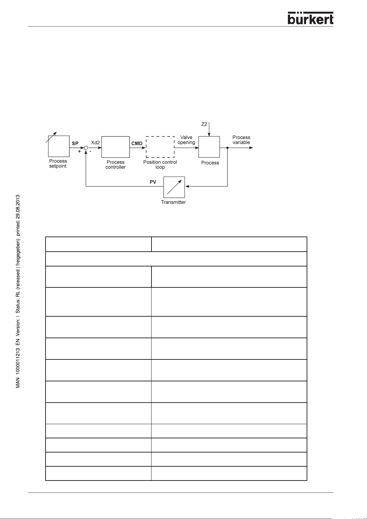
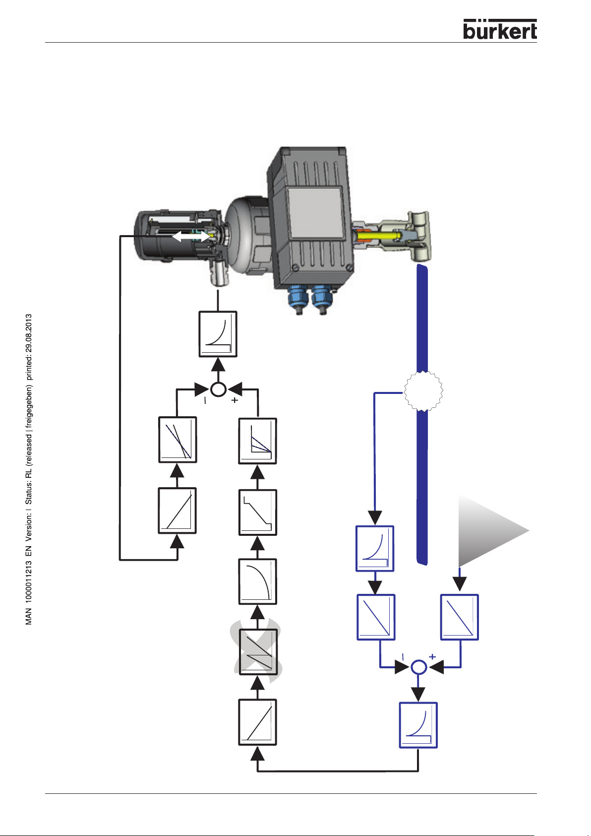
Operation as a process controller
If the SIDE Control
becomes a lower-ranking auxiliary control loop. The overall result is a cascade control system.
The process controller (as a main control loop) is implemented in the SIDE Control
controller. In this case the process setpoint (SP) is preset and compared with the actual value (PV) of
the process variable to be controlled, which is supplied by a sensor. Formation of the correcting variable
is done according to the description of the positioner. Z2 represents a disturbance acting on the
process.
Characteristic of the process controller software
(S/HART)
is operated as a process controller, the abovementioned position control
(S/HART, option)
(S/HART
(option)
as a PID
Supplementary function Effect
Positioner with supplementary functions
AUTOT UNE
Tight-closing function
Stroke limitation
Limitation of correction speed
Correction characteristic for
adaptation to the operating curve
Insensitivity range
Direction of action of the controller
setpoint
Automatic adaptation of positioner to the control valve
in use.
Valve closes tight outside the control range. A value is
specified (in %) from which the actuator is completely
exhausted (at 0 %) or pressurized (at 100 %) .
Mech. valve piston movement only within a defined
stroke range.
Actuator takes a preset time to move from OPEN to
CLOSED or from CLOSED to OPEN.
Linearization of the process curve can be carried out.
The positioner responds only above a control difference
to be specified.
Reverse of direction of action of the setpoint.
Direction of action of the actuator Reverse of direction of action of the actuator.
Safety position Valve moves to a defined safety position
Code protection Blocking of the keypad or menu
Factory reset Reset to factory settings
20 - 8635
Page 23
SYSTEM DESCRIPTION (S/HART)
Supplementary function Effect
Connectable process controller with the following characteristics (option)
Control structure PID
Parameters which can be set
Scalable inputs
Selection of setpoint specification
Hierarchic operating concept for simple operation with the following levels
Process operation
Configuration
Proportional action factor, reset time, rate time and
operating point
Position of decimal points, lower and upper scale
values of process value and setpoint
Setpoint specified either via standard signal input or via
keys
In this level, you switch between Automatic and Manual
operation.
In this level, you specify on commissioning certain
basic functions and configure supplementary functions
as required.
8635 - 21
Page 24
SYSTEM DESCRIPTION (S/HART)
POS
CMD
PV
SP
POS
X.LIMIT
DIR.ACT
X.CONTRL
DBDx
CMD
X.TIME
CUTOFF
CHARACT
P.CO FILT
P.CO SCAL
PV
Q
4 … 20 mA
SP
P.CO SCAL
22 - 8635
Schematic illustration of process control
SPLTRNGDIR.CMD
PV
SP
P.CONTRL
DBDp
PARA
INP
TUNE
Page 25
SYSTEM DESCRIPTION (S/HART)
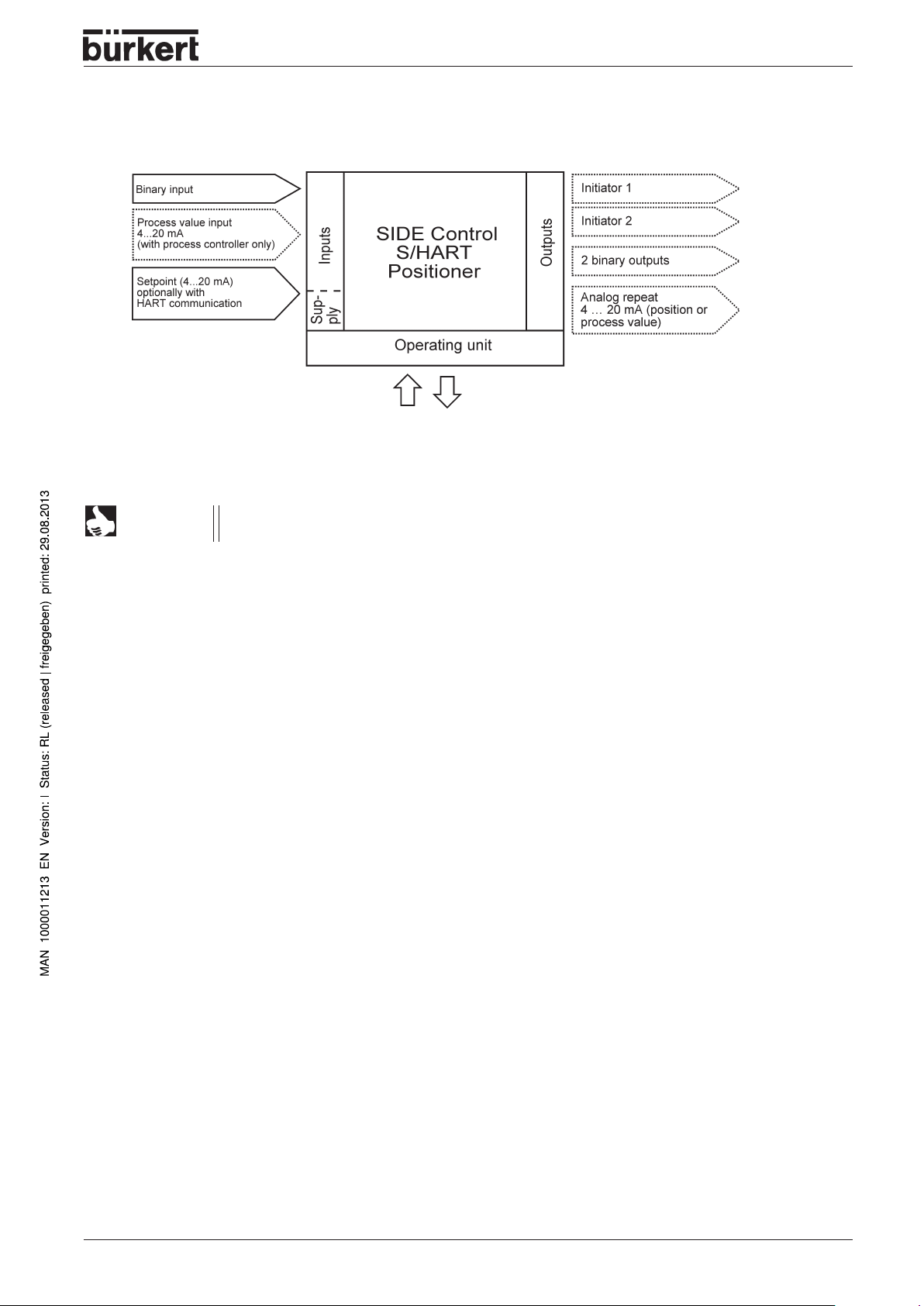
Interfaces
Note: Optional inputs and outputs are enclosed by dotted lines.
NOTE
(S/HART)
The SIDE Control
the 4 ... 20 mA signal.
(S/HART)
is a 2-conductor device, i.e. the voltage supply is provided via
8635 - 23
Page 26
SYSTEM DESCRIPTION (S/HART)
Technical data of the SIDE Control
Technical data
OPERATING CONDITIONS
Permissible ambient temperature -25 ... +65 °C (with non-Ex devices or T4/T5)
System of protection IP 65 to EN 60529
CONFORMITY TO THE FOLLOWING STANDARDS
CE Symbol Conformity wrt. EMC Guideline 89/336/EEC
Low Voltage Guidline 73/23/EEC
Explosion protection (optional) EEX ia IIC T4/T5/T6
MECHANICAL DATA
Housing dimensions, outside (WxHxD) 174 x 88 x 93 mm
Housing material Aluminium
Seal material NBR / Neoprene
Other exterior parts stainless steel (V4A)
Mass approx. 1.5 kg
(S/HART)
-25 ... +60 °C (with T6)
(only with correctly connected cable)
hard anodized and plastic-coated
(S/HART)
ELECTRICAL DATA
Connections 2 M20x1.5 bushings
with screw terminals 0.14 ... 1.5 mm
Power supply via setpoint input 4-20 mA
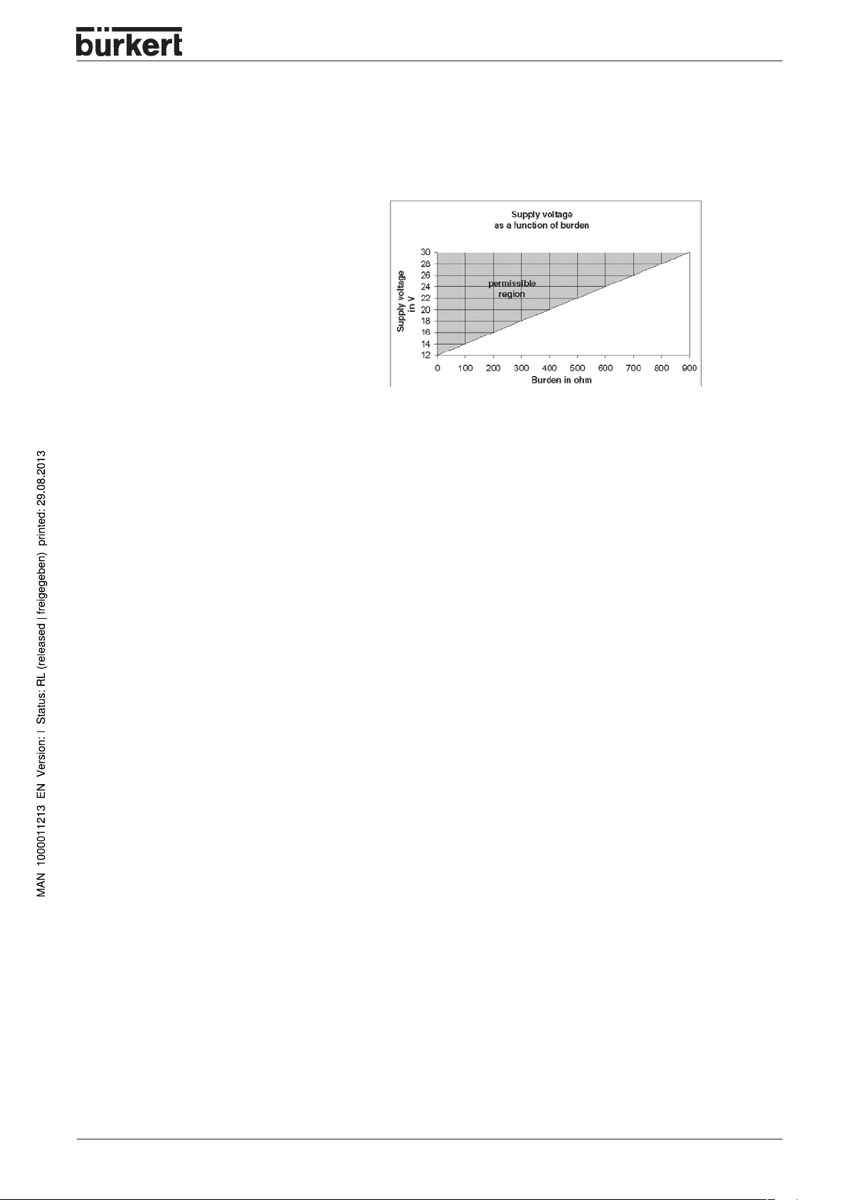
Burden voltage < 12 V DC
Burden resistance 590 Ω at 20 mA and 11.8 V DC
Process value input (option) 4-20 mA
Burden voltage 200 mV at 20 mA
Burden resistance 10 Ω
Binary input mechanical make/break contact
Inductive proximity switch (optional) to DIN EN 60947-5-6 (NAMUR)
Structural shape SJ3.5-G-N
Manufacturer Pepperl+Fuchs
Output signal for
switching amplifier to DIN EN 50227 (NAMUR)
Rated voltage U
Current (sensor uncoated) ≥ 2.1 mA
Current (sensor coated) ≤ 1.2 mA
0
8 V
2
24 - 8635
Page 27
SYSTEM DESCRIPTION (S/HART)
Analog repeat (optional) 4 ... 20 mA (electrically isolated)
Supply voltage U
Burden U
Binary outputs (optional) to EN 50 227 (electrically isolated)
Supply voltage 5 ... 11 V DC
Current in switching status OPEN < 1.2 mA
Current in switch. status CLOSE > 2.1 mA
Sense of action NO (normally open) or NC (normally closed)
max. permissible values see Declaration of Conformity
= 12 ... 30 V DC
supply
≥ 12 V + RB • 20 mA
supply
(may be parametrized)
PNEUMATIC DATA
Control medium Quality classes to DIN ISO 8573-1
Dust content Class 5:
max. 40 µm particle size
max. 10 mg/m³ particle density
Water content Class 3:
max. pressure dew point
- 20 °C or at least 10 degrees below lowest
operating temperature
Oil content Class 3: max. 1 mg/m³
Temperatur range of - 25 ... + 65 °C (with non-Ex devices or T4/T5)
compressed air - 25 ... + 60 °C (with T6)
Pressure range 1.4 ... 6.0 bar
Supply pressure
variation max. ± 10 % during operation
Air flow capacity of control valve
at 1.4 bar pressure drop
over valve ca. 55 L
/min STP for pressurizing and exhausting
N
at 6 bar pressure drop
over valve ca. 170 L
/min STP for pressurizing and exhausting
N
Self-consumption of air
in balanced state 0.0 LN/min STP
Throttle screw adjustment ratio ca.10:1
Connections G1/4'' internal thread
8635 - 25
Page 28
SYSTEM DESCRIPTION (S/HART)
Factory settings
Function Factory setting
CHARACT CHA LIN
CUTOFF CUT
DIR.CMD DIR.CRISE
DIR.ACT DIR.ARISE
SPLTRNG SR
X.LIMIT LIM
X.TIME
T.OPN
T.CLS
After execution of
OUTPUT
OUT ANL:
OUT POS OUT 4
OUT BIN:
OUT DEV DEV 5.0 NORM OPN
SAFEPOS
BIN-IN B.IN SPOS / NORM OPN
(S/HART)
= 0 %;
= 0 (%); SR = 100 (%)
= 0 %,
Values determined by
Values determined by
SETFACT
'
20 A
0
CUT
LIM
:1 s
= 100 %
= 100 %
AUTOTUNE
AUTOTUNE
Function Factory setting
X.CONTRL
X.CO DBND
X.CO PARA
KX
KX
After execution of
P.CONTRL
P.CO DBND
P.CO PARA
KP
TN
TV
X0
P.CO SETP SETP INT
P.CO FILT
P.CO SCAL PV
P.CO TUNE D’ACT
CODE CODE 0000
1 %
Values determined by
Values determined by
SETFACT
1 %
1.00
999.9
0.0
0
0
000.0
:1
, PV
AUTOTUNE
AUTOTUNE
100.0
NOTE
The functions and factory settings shown in grey are optionally valid with
analog repeat
(OUTPUT)
or with process controller
(P.CONTRL)
.
26 - 8635
Page 29

SYSTEM DESCRIPTION (PROFIBUS PA)
SYSTEM DESCRIPTION
(PROFIBUS PA)
Construction of SIDE Control
Illustration ............................................................................................................................................................................................................................................. 28
Features
Options
Functional diagram of the SIDE Control
control valve with single-acting diaphragm actuator ..................................................................................................................... 30
................................................................................................................................................................................................................................................. 29
.................................................................................................................................................................................................................................................... 29
Operation as a positioner
Characteristics of the positioner software ................................................................................................................................................. 32
Schematic illustration of position control
Interfaces
(PROFIBUS PA)
Technical data of the SIDE Control
Technical data
Factory settings
(PROFIBUS PA)
(PROFIBUS PA)
(PROFIBUS PA)
(PROFIBUS PA)
(PROFIBUS PA)
...................................................................................................................................................... 33
.............................................................................................................................................................................................
(PROFIBUS PA)
............................................................................................................................................................................. 35
........................................................................................................................................................................
............................................................................................................................... 28
in connection with a
............................................................................................................................................. 31
.............................................................................................................
34
35
36
8635 - 27
Page 30
SYSTEM DESCRIPTION (PROFIBUS PA)
Construction of SIDE Control
The SIDE Control
with single-acting linear or part-turn actuators.
The SIDE Control
(e.g. process control system). The momentary valve position is reported via the bus.
For detailled information on commissioning a PROFIBUS PA branch, we recommend the
Commissioning Guidelines
(PROFIBUS PA)
(PROFIBUS PA)
by the PROFIBUS Users Organization (PUO).
is a digital positioner for pneumatically operated continuous valves
can be controlled via PROFIBUS PA from a central automation system
(PROFIBUS PA)
Illustration
DIP switch
(device address)
PROFIBUS
Display with 3 operating keys
Screw terminal
Clamping screw
(for attaching the
bus screen)
Bushings
M20 x 1.5
Throttle screw
Earthing
(grounding) screw
28 - 8635
Page 31

SYSTEM DESCRIPTION (PROFIBUS PA)
Features
•
Position sensor
Very high resolution conductive plastic potentiometer
• Microprocessor controlled electronics
for signal processing, control and driving the piezoelectric positioning system
•
Operating elements
The device can be set (configuration and parametrization) locally via three inside keys. An inside, 8digit, 16-segment LC display is provided, which can also show the set point or actual value.
Positioning system
•
A piezoelectric positioning system serves to drive the valve actuator.
•
Electrical interfaces
M20 bushings with screw terminals
•
Pneumatic interfaces
G1/4’’ interior thread
•
Housing
Aluminium housing (hard anodized and plastic-coated) with swing-up cover and captive screws.
Attachment
•
to linear actuators to NAMUR recommendation (DIN 534 T6) or to part-turn actuators to VDI/VDE 3845)
Options
• Position feedback via 2 inductive proximity switches (initiators).
• Integral attachment to Bürkert continuous valves.
8635 - 29
Page 32

SYSTEM DESCRIPTION (PROFIBUS PA)
Functional diagram of the SIDE Control
(PROFIBUS PA)
connected to a control valve with single-acting diaphragm
actuator
SIDE Control
(PROFIBUS PA)
Actual position
External position
setpoint via
PROFIBUS PA
Pressure
supply
Exhaust
air
Positioner
Positioning system
pressurize
exhaust
Position
sensor
Lever
mechanism
Pneumatic
actuator
(single-acting)
Valve
(actuator)
NOTE
In the case of Integral attachment of the SIDE Control
(PROFIBUS PA)
to a Bürkert
continuous valve, the position sensor is situated outside the SIDE Control
BUS PA)
on the actuator and is connected to the latter with a cable.
(PROFI-
30 - 8635
Page 33

S
YSTEM DESCRIPTION
(PROFIBUS PA)
Operation as a positioner
The SIDE Control
sensor measures the actual position (POS) of the actuator. The controller compares this actual value of
the position with the setpoint (CMD), which may be set via the PROFIBUS PA. If a control difference
(Xd1) exists, a pulse-width modulated voltage signal is sent to the positioning system as the correcting
variable. If the difference is positive, the pressurizing piezoelectric valve is driven via output B1; if it is
negative, the exhausting piezoelectric valve is driven via output E1. In this way, the position of the
actuator is altered until the control difference is 0. Z1 represents a disturbance.
Position
setpoint
(PROFIBUS PA)
Positioner Positioning system
(PROFIBUS PA)
controls the position of the pneumatic actuator, whereby the position
Valve opening
Continuous
(piezoelectric valves)
valve
Position control loop
Position sensor
8635 - 31
Page 34

SYSTEM DESCRIPTION (PROFIBUS PA)
Characteristics of the positioner software
Supplementary function Effect
Positioner with supplementary functions
AUTOT UNE
Tight-closing function
Stroke limitation
Limitation of correction speed
Correction characteristic for
adaptation to the operating curve
(via PROFIBUS PA)
Insensitivity range
Direction of action of the controller
setpoint
Direction of action of the actuator Reverse of direction of action of the actuator
Automatic adaptation of positioner to the control valve
in use.
Valve closes tight outside the control range. A value is
specified (in %) from which the actuator is clompletely
exhausted (at 0 %) or pressurized (at 100 %).
Mech. valve piston movement only within a defined
stroke range.
Actuator takes a preset time to move from OPEN to
CLOSED or from CLOSED to OPEN.
Linearization of the process curve can be carried out.
The positioner responds only above a control difference
to be specified.
Reverse of direction of action of the setpoint
Safety position Valve moves to a defined safety position
Factory reset Reset to factory settings
Communication via PROFIBUS PA protocol
32 - 8635
Page 35

POS
SYSTEM DESCRIPTION (PROFIBUS PA)
CMD
POS
X.LIMIT
DIR.ACT
X.CONTRL
DBDx
CMD
X.TIME
CHARACT CUTOFF
Setpoint
setting via
Schematic illustration of position control
CMD
PROFIBUS PA
DIR.CMD
8635 - 33
Page 36

SYSTEM DESCRIPTION (PROFIBUS PA)
Interfaces
Note: Optional inputs and outputs are enclosed by dotted lines
NOTE
(PROFIBUS PA)
The SIDE Control
provided via the PROFIBUS PA signal.
(PROFIBUS PA)
is a 2-conductor device, i.e. the voltage supply is
34 - 8635
Page 37

SYSTEM DESCRIPTION (PROFIBUS PA)
Technical data of the SIDE Control
Technical data
OPERATING CONDITIONS
Permissible ambient - 25 ... + 65 °C (with non-Ex devices or T4/T5)
temperature - 25 ... + 60 °C (with T6)
System of protection IP 65 to EN 60529
CONFORMITY TO THE FOLLOWING STANDARDS
CE symbol Conformity wrt. EMC Guideline 89/336/EEC
Low Voltage Guidline 73/23/EEC
Explosion protection (optional) EEX ia IIC T4/T5/T6
MECHANICAL DATA
Housing dimensions, outside (W x H x D) 174 x 88 x 93 mm
Housing material Aluminium
Seal material NBR / Neoprene
Other exterior parts stainless steel (V4A)
Mass approx. 1.5 kg
(PROFIBUS PA)
(only with correctly connected cable)
hard anodized and plastic-coated
(PROFIBUS PA)
ELECTRICAL DATA
Connections 2 M20 x 1.5
bushings with screw terminals 0.14 ... 1.5 mm
Power supply via PROFIBUS PA signal
to Ex segment coupler 9 ... 15 V DC (Ex)
to segment coupler 9 ... 24 V DC (NonEx)
Operating current from bus 12 mA ± 7 % without FDE
Fault current protection 5 mA ± 10 % FDE
Binary input mechanical make/break contact
Inductive proximity switch (optional) to DIN EN 60947-5-6 (NAMUR)
Structural shape SJ3,5-G-N
Manufacturer Pepperl+Fuchs
Output signal for
switching amplifier to DIN EN 50227 (NAMUR)
Rated voltage U
Current (sensor uncoated) ≥ 2.1 mA
Current (sensor coated) ≤ 1.2 mA
0
8 V
2
8635 - 35
Page 38

SYSTEM DESCRIPTION (PROFIBUS PA)
PNEUMATIC DATA
Control medium Quality classes to DIN ISO 8573-1
Dust content Class 5:
max. 40 µm particle size
max. 10 mg/m³ particle density
Water content Class 3:
max. pressure dew point
- 20 °C or at least 10 degrees below lowest
operating temperature
Oil content Class 3: max. 1 mg/m³
Temperature range of - 25 ... + 65 °C (with non-Ex devices or T4/T5)
compressed air - 25 ... + 60 °C (with T6)
Pressure range 1.4 ... 6.0 bar
Supply pressure
variation ± 10 % during operation
Air flow capacity of control valve
at 1.4 bar pressure drop
over valve ca. 55 l
at 6 bar pressure drop
over valve ca. 170 l
Self-consumption of air in
balanced state 0.0 lN/min
Throttle screw adjustment ratio ca. 10:1
Connections G1/4'' internal thread
/min STP for pressurizing and exhausting
N
/min STP for pressurizing and exhausting
N
Factory settings
Function Factory setting
CUTOFF CUT
(PROFIBUS PA)
= 0 %;
DIR.CMD DIR.CRISE
DIR.ACT DIR.ARISE
X.LIMIT LIM
= 0 %,
X.TIME
T.OPN
T.CLS
After execution of
Values determined by
Values determined by
SETFACT
:1 s
CUT
LIM
= 100 %
= 100 %
AUTOTUNE
AUTOTUNE
Function Factory setting
SAFEPOS
0
BIN-IN B.IN SPOS / NORM OPN
X.CONTRL
X.CO DBND
1 %
X.CO PARA
KX
KX
After execution of
Values determined by
Values determined by
SETFACT
:1
AUTOTUNE
AUTOTUNE
36 - 8635
Page 39

INSTALLATION
INSTALLATION
Attachment and assembly ............................................................................................................................................................................................... 38
Complete system with Bürkert continuous valve from series 27xx ............................................................................ 38
Attachment to a continuous valve with linear actuator acc. to NAMUR
Attachment to a continuous valve with part-turn actuator
...................................................................................................... 42
................................................................ 39
Fluidic connection......................................................................................................................................................................................................................... 44
Electrical connection
Electrical connection
(S/HART)
...............................................................................................................................................................................
(PROFIBUS PA)
..........................................................................................................................................................
45
46
8635 - 37
Page 40

INSTALLATION
Attachment and assembly
The SIDE Control may be attached to different continuous valves. The valves which may be used are
continuous valves with a linear activator to NAMUR recommendation (DIN IEC 534 T6) and such with a
part-turn actuator to VDI/VDE 3845. Furthermore, the SIDE Control is available completely
preassembled on a Bürkert continuous valve from series 27xx.
Complete system with Bürkert continuous valve from series 27xx
The SIDE Control is available in combination with Bürkert continuous valves from the series 27xx as a
completely preassembled and tested system.
ATTENTION!
38 - 8635
The connecting line from the SIDE Control to the external positioning sensor shall
not be lengthened. Only the positioning sensor supplied shall be connected to the
SIDE Control.
If manipulations are carried out, the EX approval will become void!
Page 41

INSTALLATION
Attachment to a continuous valve with linear actuator acc. to NAMUR
Transmission of the valve position to the position sensor built into the SIDE Control is via a lever (to
NAMUR).
Add-on kit to linear activator (Id no. 787 215)
(obtainable from Bürkert as an accessory)
Serial
no.
1 1 NAMUR attachment bracket IEC 534
2 1 U-piece
3 2 Clamping piece
4 1 Driving pin
5 1 Conical roller
6a 1 NAMUR lever for stroke range 3 - 35 mm
6b 1 NAMUR lever for stroke range 35 - 130 mm
7 2 U-bolt
8 4 Hex screw DIN 933 M8 x 20
9 2 Hex screw DIN 933 M8 x 16
10 6 Lock washer DIN 127 A8
11 6 Washer DIN 125 B 8.4
12 2 Washer DIN 125 B 6.4
Quantity
Designation
13 1 Spring VD-115E 0.70 x 11.3 x 32.7 x 3.5
14 1 Spring washer DIN 137 A6
15 1 Retaining washer DIN 6799 - 3,2
16 3 Lock washer DIN 127 A6
17 3 Hex screw DIN 933 M6 x 25
18 1 Hex nut DIN 934 M6
19 1 Square nut DIN 557 M6
21 4 Hex nut DIN 934 M8
22 1 Guide bushing 6.2 x 9.9 x 15 x 3.5
8635 - 39
Page 42

INSTALLATION
Assembly
Mount U-piece (2) using clamping pieces (3), hex screws (17) and lock washers (16) on actuator
spindle.
Select the short lever (Table
to linear actuator,
Assemble the lever (if not preassembled).
The distance of the driving pin from the axle should be
equal to the actuator stroke. This results in a swing angle of
the lever of 60°. This assures that the position sensor works
with good resolution. The scale printed on the lever is irrelevant.
Serial no. 6b), depending on the actuator stroke.
Add-on kit to linear actuator,
Serial no. 6a) or long lever (Table
Add-on kit
Swing angle of
lever (60°)
Separation = stroke of actuator
Push the lever onto the axle of the SIDE Control and screw it tight.
Fix attachment bracket (1) with hex screws (9), lock washers (10) and washers (11) to the rear side
of the SIDE Control.
NOTE
Which M8 thread on the SIDE Control is
chosen depends on the size of the actuator
To determine the correct position, hold the
SIDE Control with bracket against the
actuator. The conical roller (5) on the lever
of the position sensor must be able to move
freely in U-piece (2) on the actuator over
the entire stroke. At 50% stroke, the lever
position should be roughly horizontal (see
under
Alignment of the lever mechanism
).
40 - 8635
Page 43

INSTALLATION
Actuator with cast frame
Fix the SIDE Control with bracket by means of one or more hex screws (8), washers (11) and lock
washers (10) to the cast frame.
Actuator with post yoke
Fix the SIDE Control with bracket with U-bolts (7),
washers (11), lock washers (10) and hex nuts (21) to the post yoke.
Alignment of the lever mechanism
The lever mechanism can only be aligned properly when the device has been connected electrically
and pneumatically.
In the manual mode, move the actuator to half stroke (corresponding to scale on actuator).
Move the device vertically until the lever is horizontal.
Fix the device finally to the actuator.
8635 - 41
Page 44

INSTALLATION
Attachment to a continuous valve with part-turn actuator
The axle of the position sensor built into the SIDE Control is coupled directly to the axle of the part-turn
actuator.
Add-on kit to part-turn activator (Id no. 651 741)
Serial
no.
1 1 Adapter
2 2 Setscrew DIN 913 M4 x 4
3 4 Cap screw DIN 933 M6 x 12
4 4 Lock washer B6
Quan-
tity
Designation
(obtainable from Bürkert as an
accessory)
Other accessories required
Attachment bracket with fixing screws (acc. to VDI/VDE 3845) - available from the manufacturer of the
part-turn actuator.
Assembly
Determine the orientation of attachment of the
SIDE Control (parallel to the actuator or rotated
by 90°).
Determine the basic position and direction of
rotation of the actuator.
Push adapter (1) onto the axle of the SIDE
Control and fix it with 2 setscrews (2). One of
the setscrews should press onto the flat on the
axle (
to prevent slip!
the axle of the SIDE Control can move only in
one of the ranges shown below in the drawings
observe the flat on the axle!
Swing angle 90°
Flat on shaft!
). It must be assured that
.
Swing angle 90°
Flat on shaft!
42 - 8635
Page 45

INSTALLATION
Place the SIDE Control on the bracket and fix it with 4 cap screws (3) and lock washers (4).
Place the SIDE Control with the bracket on the part-turn actuator and fix it.
NOTE
If after starting the function
alignment of the axle of the SIDE Control to the axle of the actuator is incorrect.
In this case, check the alignment as described above.
X.TUNE
the message
X.ERR 5
appears in the LC display, the
Then repeat the function
X.TUNE.
8635 - 43
Page 46

INSTALLATION
Fluidic connection
The locations of the fluidic connections are shown in the following drawing:
Exhaust
connection
3
Connect supply pressure to connection 1.
Connect the service connection 2 to the chamber of the single-acting actuator.
If possible, connect a silencer or the like to connection 3. If the connection is left open, there is a risk
of water splashes entering the SIDE Control.
Supply
pressure
connection
1
Service
connection
2
44 - 8635
Page 47

INSTALLATION
Switch (make contact
or break contact)
11
12
81
82
13
14
41
42
51
52 31
32
86
85
83
84
Electrical connection
To make electrical connections, open the cover of the SIDE Control
screws.
Terminal
designation
Allocation External connection
(S/HART)
(S/HART)
by unscrewing the 2
11 + Setpoint + 4 ... 20 mA signal
12 - Setpoint - GND
13 + Process value + (option) 4 ... 20 mA signal
14 - Process value - (option) GND
31 Actual value output + (option)
32 Actual value output - (option)
41 + Initiator 1+ (option)
42 - Initiator 1- (option)
51+ Initiator 2+ (option)
52 - Initiator 2- (option)
81 Binary input +
82 Binary input -
83 Binary output 1+ (option)
84 Binary output 1- (option)
85 Binary output 2+ (option)
Switching amplifier
to EN 50227
Switching amplifier
to EN 50227
86 Binary output 2- (option)
ATTENTION!
During the electrical connection of the inherently safe circuits, always observe the
data in the attached Certificate of Conformity!
HINWEIS
Connection of a potential equalization conductor (PE) to the electronics is unnecessary.
1) Burden resistance RB: see Chapter
Technical Data
8635 - 45
Page 48

INSTALLATION
Electrical connection
To make electrical connections, open the cover of the SIDE Control
unscrewing the 2 screws.
Configuration of the terminals
Bus (+)
Bus (-)
Bus (+)
Bus (-)
81
82
N.C.
N.C.
41 (+)
42 (-)
51 (+)
52 (-)
(PROFIBUS PA)
(PROFIBUS PA)
by
Terminal
designation
BUS (+) PROFIBUS-PA (IN) to IEC 1158-2 (either polarity between input terminals)
BUS (-) PROFIBUS-PA (IN)
BUS (+) PROFIBUS-PA (OUT) to IEC 1158-2 (either polarity between output terminals)
BUS (-) PROFIBUS-PA (OUT)
81 Binary input connected via switch (make contact)
82 Binary input
N.C. not connected
N.C. not connected
41 + Initiator 1 + (option)
42 - Initiator 1 - (option)
51 + Initiator 2 + (option)
52 - Initiator 2 - (option)
Allocation External connection
to terminal 82
Switching amplifier
to EN 50227
Switching amplifier
to EN 50227
Use screened cable for connecting the bus and the binary input in order to assure reliability and EC
conformity. The cable screens can be attached using the clamping screw (on the post between the M20
bushings). The cable screens must be attached at both ends. On the outside of the housing there is a
further screw for further connection to a suitable earthing (grounding) point.
ATTENTION!
46 - 8635
During the electrical connection of the inherently safe circuits, always observe the
data in the attached Certificate of Conformity!
Page 49

INDUCTIVE PROXIMITY SWITCHES (S/HART, PROFIBUS PA, OPTION)
INDUCTIVE
PROXIMITY SWITCHES
(S/HART, PROFIBUS PA,
OPTION)
Description of the inductive proximity switches................................................................................................................................. 48
Configuration of the adjusting wheels
Settings........................................................................................................................................................................................................................................................... 49
Setting with one inductive proximity switch ................................................................................................................................................49
Setting with two inductive proximity switches
Definition of the end positions with part-turn actuators .......................................................................................................... 49
(option)
...................................................................................................................................
......................................................................................................................................... 49
48
8635 - 47
Page 50

INDUCTIVE PROXIMITY SWITCHES (S/HART, PROFIBUS PA, OPTION)
Description of the inductive proximity switches
Any actuator position can be registered with an inductive proximity switch. Depending on the version of the
device, one or two inductive proximity switches are installed. The output signals can be processed with
switching amplifiers to „NAMUR“ to EN 50227 or VDE 0660 T 212.
As soon as the control flags installed in the SIDE Control enter the fork-shaped inductive proximity switch,
the current changes.
Proximity switch operated: current ≤1.2 mA
Proximity switch not operated: current ≥ 2.1 mA
The control flags are designed such that the signal is then maintained until the end position is reached.
inductive
proximity switch
control flag
adjusting
wheel
7
1
e
l
c
r
S
e
g
m
e
i
c
f
o
t
n
Configuration of the adjusting wheels
NOTE
Even when the device is equipped with only one proximity switch, both adjusting wheels are
installed. In this case only SR1 is active.
°
0
(option)
48 - 8635
SR1
SR2
Page 51

Settings
INDUCTIVE PROXIMITY SWITCHES (S/HART, PROFIBUS PA, OPTION)
NOTE
First put the device into operation, as described in the chapter
Functions
is displayed correctly.
. The function
AUTOTUNE
must have been executed, so that the actuator stroke
Operation and Control
Setting with one inductive proximity switch
The upper end position is to be set (Position 1 with part-turn actuators)
Move the actuator in the manual mode to the position in which initiation is to take place. Turn adjusting
wheel SR1 to the right until the current jumps from ≥ 2.1 mA to ≤ 1.2 mA.
The lower end position is to be set (Position 2 with part-turn actuators)
Move the actuator in the manual mode to the position in which initiation is to take place. Turn adjusting
wheel SR1 to the left until the current jumps from ≥ 2.1 mA to ≤ 1.2 mA.
Setting with two inductive proximity switches
The upper end position is to be set (Position 1 with part-turn actuators)
Move the actuator in the manual mode to the position in which initiation is to take place. Turn adjusting
wheel SR2 to the right until the current jumps from ≥ 2.1 mA to ≤ 1.2 mA.
On turning the adjusting wheel, take care that the other adjusting wheel is not turned.
The lower end position is to be set (Position 2 with part-turn actuators)
Move the actuator in the manual mode to the position in which initiation is to take place. Turn adjusting
wheel SR2 to the left until the current jumps from ≥ 2.1 mA to ≤ 1.2 mA.
On turning the adjusting wheel, take care that the other adjusting wheel is not turned.
Definition of the end positions with part-turn actuators
SIDE Control
Position 1
Part-turn actuator
Position 2
8635 - 49
Page 52

INDUCTIVE PROXIMITY SWITCHES (S/HART, PROFIBUS PA, OPTION)
50 - 8635
Page 53

OPERATING AND CONTROLLER FUNCTIONS
OPERATING AND
CONTROLLER FUNCTION
Operating and display elements............................................................................................................................................................................. 52
Operating levels
............................................................................................................................................................................................................................... 52
Commissioning and set-up as a positioner............................................................................................................................................ 53
Procedure for specifying the basic settings.............................................................................................................................................. 53
Main menu for settings on commissioning
Description of the procedure
....................................................................................................................................................................................... 55
................................................................................................................................................. 55
Configuring the supplementary functions ................................................................................................................................................. 59
Keys in the configuration level................................................................................................................................................................................... 59
Configuration menu
Supplementary functions
................................................................................................................................................................................................................. 59
................................................................................................................................................................................................. 62
Operating the process ........................................................................................................................................................................................................... 85
Changing between operating modes ................................................................................................................................................................ 85
Operating mode AUTOMATIC
Meaning of the keys in the operating mode AUTOMATIC.................................................................................................... 86
(S/HART)
..................................................................................................................................................
86
Displays in the operating mode AUTOMATIC
Operating mode AUTOMATIC
Meaning of the keys in the operating mode AUTOMATIC ..................................................................................................... 87
Displays in the operating mode AUTOMATIC
(PROFIBUS PA)
...................................................................................................................................... 86
.............................................................................................................................
........................................................................................................................................ 87
87
Operating mode MANUAL............................................................................................................................................................................................... 88
Meaning of the keys in the operating mode MANUAL ................................................................................................................ 88
Displays in the operating mode MANUAL
.................................................................................................................................................. 88
8635 - 51
Page 54

OPERATING AND CONTROLLER FUNCTIONS
Operating and display elements
The SIDE Control is equipped with a 3-key operating and display element with an LC display. The
functions of the keys are described in the following sections.
MANUAL / AUTOMATIC key
LED
(without function)
Arrow key up Arrow key down
Operating levels
Operation of the SIDE Control is done via two operating levels:
• Process operating level
After the device is switched on, the process operating level is active. In this level, you can switch
between the operating modes
In the
AUTOMATIC
process controller
mode, position or process control run (process control only with the option
). In the
• Configuration level
In the configuration level, you can specify the first commissioning of the basic functions and
configure supplementary functions if needed.
AUTOMATIC
MANUAL
and
mode, the valve can be manually opened and closed.
MANUAL
.
52 - 8635
Process operating level
MANUAL AUTO-
MATIC
5 sec
Configuration level
Basic
functions
End
Supplementary
functions
Page 55

OPERATING AND CONTROLLER FUNCTIONS
Commissioning and set-up as a positioner
➔ Before commissioning, execute the fluidic and electrical installations.
Procedure for specifying the basic settings
➔ On first commissioning of the SIDE Control, make the following basic settings:
• Enter the control function of the actuator used.
• Start the automatic adaptation of the controller to the current operating conditions
(
AUTOTUNE
Configuration of the keys
).
MANUAL/AUTOMATIC Switch between main and sub-menu
key items, e.g.
Arrow keys Switch between equal-ranking menu
items, e.g.
ADDFUNCT - CHARACT
ADDFUNCT - X.TUNE
Factory settings of the controller
Function Factory setting
CHARACT CHA LIN
CUTOFF CUT
DIR.CMD DIR.CRISE
DIR.ACT DIR.ARISE
SPLTRNG SR
X.LIMIT LIM
X.TIME
T.OPN
T.CLS
After execution of
OUTPUT
OUT ANL:
OUT POS OUT 4'20 A
OUT BIN :
OUT DEV DEV 5.0 NORM OPN
SAFEPOS 0
BIN-IN B.IN SPOS / NORM OPN
= 0 %;
= 0 (%);
= 0 %,
Values determined by
Values determined by
SETFACT
CUT
SR
LIM
:1 s
= 100 %
= 100 (%)
= 100 %
AUTOTUNE
AUTOTUNE
(S/HART)
Function Factory setting
X.CONTRL
P.CONTRL
CODE CODE 0000
X.CO DBND 1 %
X.CO PARA
KX
KX
After execution of
P.CO DBND 1 %
P.CO PARA
KP 1.00
TN 999.9
TV 0.0
X0 0
P.CO SETP SETP INT
P.CO FILT 0
P.CO SCAL PV 000.0, PV 100.0
P.CO TUNE D’ACT
Values determined by
Values determined by
SETFACT
:1
AUTOTUNE
AUTOTUNE
NOTE
The functions and factory settings shown in grey are optionally valid with analog
repeat
(OUTPUT)
or with process controller
(P.CONTRL).
8635 - 53
Page 56

OPERATING AND CONTROLLER FUNCTIONS
Factory settings of the controller
Function Factory setting
CUTOFF CUT
DIR.CMD DIR.CRISE
DIR.ACT DIR.ARISE
X.LIMIT LIM
X.TIME
T.OPN
T.CLS
After execution of
= 0 %;
= 0 %,
Values determined by
Values determined by
SETFACT
CUT
LIM
:1 s
= 100 %
= 100 %
AUTOTUNE
AUTOTUNE
(PROFIBUS PA)
Function Factory setting
SAFEPOS 0
BIN-IN B.IN SPOS / NORM OPN
X.CONTRL
X.CO DBND 1 %
X.CO PARA
KX
KX
After execution of
Values determined by
Values determined by
SETFACT
:1
AUTOTUNE
AUTOTUNE
54 - 8635
Page 57

OPERATING AND CONTROLLER FUNCTIONS
Main menu for settings on commissioning
Operating mode
AUTOMATIC
MANUAL
or
5 s
EEPROM
Description of procedure
ADDFUNCT
X.TUNE
5 s
X.TUNE END
END
ADDFUNCT
see section
➔ Jump over this menu item on first commissioning.
Configuring the supplementary functions.
X.TUNE
-
AUTOTUNE
for positioners
Start the automatic adaptation of the positioner to the current operating
conditions
The following functions are initiated automatically:
• Adaptation of the sensor signal to the (physical) stroke of the valve used.
• Determination of parameters for driving the integral piezoelectric positioning system
• Setting of the controller parameters of the positioner.
Optimization is done according to the criteria: as short a correcting time as possible and freedom
from overshoot.
(X.TUNE)
8635 - 55
Page 58

OPERATING AND CONTROLLER FUNCTIONS
Proceed as follows:
➔ Switch on the voltage supply.
➔ Depress the MANUAL/AUTOMATIC key
➔ Press the ARROW key
➔ Depress the MANUAL/AUTOMATIC key for 5 seconds - start of
➔ After completion of
conditions.
➔ Press the ARROW key - scroll to menu item
➔Press briefly the MANUAL/AUTOMATIC key - jump to mode
AUTOTUNE,
- scroll to menu item
press briefly the MANUAL/AUTOMATIC key - store operating
for 5 seconds - switch to configuration level.
X.TUNE.
END
AUTOMATIC orMANUAL
Display message Description
TUNE 5
Countdown from 5 to 0 to start
TUNE 4 AUTOTUNE
:
TUNE 0
¦
X.T INIT
¦
X.T A1-P
¦
X.T TOPN
¦
X.T TCLS
:
X.TUNE END
Display of the
at the moment (progress is indicated by a rotating
bar to the left of the display)
Flashing display
AUTOTUNE
→→
→ end of
→→
phase in progress
AUTOTUNE
X.TUNE.
X.ERR
X Message on occurrence of an error
NOTE
ATTENTION!
(to right of display: error number, see chapter
Maintenance and Error Elimination on the Controller
On commissioning the SIDE Control, execution of
The positioner determines the optimum settings for the valve used and the current
operating conditions (supply pressure).
If the supplementary function
execution of
X.CO.DBND
actuator (see section
The function
since otherwise pressure variations in the valve may cause faulty adaptation of the
controller. The supply pressure (pneumatic auxiliary energy) should be set to the
value that will exist in later operation!
During execution of the
its momentary position. For this reason, never execute
is running!
X.TUNE
occurs additionally as a function of the frictional behaviour of the
, automatic determination of the positioner dead band
X.CONTRL).
X.TUNE
should be executed with the valve unpressurized or shut off,
X.CONTRL
AUTOTUNE
is present in the main menu during
function, the valve moves autonomously from
X.TUNE
)
is
absolutely
AUTOTUNE
necessary.
when a process
56 - 8635
Page 59

OPERATING AND CONTROLLER FUNCTIONS
MANUAL
Access to the manual
TUNE
FUNCTIONS
TUNE
functions can be obtained by the selecting of
X.TUNE
in the main menu
and briefly pressing the MANUAL/AUTOMATIC key or aborting the countdown by releasing the MANUAL/AUTOMATIC key.
AUTOTUNE MANUAL TUNE
release
X.TUNE
5 s
Countdown
TUNE 5
TUNE 4
TUNE 3
TUNE 2
TUNE 1
TUNE-END
TUNE-POS
POS MIN
A.LIM YES
A.LIM NO
EEPROM
POS-MAX POS-MIN
move to max.
position
POS MAX
move to min.
EEPROM
position
TUNE-PWM
YB XXX
YE XXX
TUNE 0
change min.PWM-T.V. for
pressurizing valve
Display of opening time (s)
X.T XXX
TUNE END
TUNE-AIR
T.OPN XX
T.CLS XX
Display of closing time (s)
The following parameters, which are determined automatically during
change min. PWM-T.V. for
exhausting valve
X.TUNE
, may be preset or
changed afterwards manually.
TUNE-END
TUNE-POS
The
AUTOTUNE
- Return to main menu
- Preset end positions
function determines the end positions of the control armature automatically on the
basis of the physical stops. Certain armatures (e.g. continuously turning butterfly valves) possess no
physical end stop, so that the end positions must be manually preset by means of
immediately following
AUTOTUNE
takes over the manual end position settings and continues with
TUNE-POS
. An
setting the positioning system and optimization of the positioner.
NOTE
If a manual preset of the end positions with
before
execution of
AUTOTUNE
.
TUNE-POS
is necessary, it must be done
8635 - 57
Page 60

OPERATING AND CONTROLLER FUNCTIONS
TUNE-PWM -
Readjustment of minimum PWM pulse-duty factor for driving the piezoelectric
valves integrated in the SIDE Control
The
AUTOTUNE
valves integrated in the SIDE Control. These values may deviate from the optimum because of
unfavourable frictional behaviour of the actuator. With
lowest possible speed results for both directions of movement.
NOTE
TUNE-AIR -
The required maximum air flow capacity of the internal positioning system depends on the volume of the
actuator. Ideal control behaviour of the positioner is obtained with an air flow capacity that leads to an
opening or closing time of the armature of 1 ... 2 s. For this reason, the SIDE Control is equipped with a
throttle screw to vary the maximum air flow capacity of the internal positioning system. The position of
the throttle screw is to be seen in the chapter
adjustment of this throttle screw is made by means of
determined by cyclic opening and closing of the valve and displayed.
NOTE
function determines automatically the required PWM-PDF for driving the piezoelectric
The function
TUNE-PWM
TUNE-PWM
must be executed
, you can reajust it such that the
after
AUTOTUNE
!
Adaptation of the opening and closing times of the process valve
The function
TUNE-AIR
System Description / Structure of the SIDE Control
TUNE-AIR
must be executed
, whereby the corresponding times are
after
AUTOTUNE
!
. The
ATTENTION!
To avoid cause faulty adaptation of the controller, be sure to execute X.TUNE at the
supply pressure (= pneumatic auxiliary energy) that will exist in later operation.
The function
pressure to exclude disturbances from forces resulting from flow.
END
- Quitting the main menu
➔ To quit the main menu, select the menu item
On the right of the display, the software version is shown (END XX). After pressing the MANUAL/
AUTOMATIC key, the message EEPROM appears on the display for ca. 3 ... 5 s while the changes
are being stored. Afterwards, the device is back in the mode in which it was before switching over to
the main menu (MANUAL or AUTOMATIC).
X.TUNE
should be executed preferably without operating medium
END
with the arrow keys .
58 - 8635
Page 61

OPERATING AND CONTROLLER FUNCTIONS
Configuring the supplementary functions
NOTE
The operating concept for the SIDE Control is based on a strict separation between the
basic and supplementary functions. In the delivered state, only the basic functions
ADDFUNCT, X.TUNE and END
For more demanding control applications, you can select and specify supplementary
functions in the configuration level.
are activated. These suffice for normal operation.
Keys in the configuration level
Press key in menu in a selected and confirmed menu item
Scroll up Increment (increase) numeric
(select) value
Scroll down Decrement (decrease) numeric
(select) value
Press key in menu in menu
ADDFUNCT
Confirm selected menu Confirm selected menu item of supplementary
item menu to add it to the main menu. The menu
item is marked with an asterisk (*) in the
supplementary menu.
Confirm values set The menu item appears in the main menu and
can be selected and edited there.
Confirm the menu item selected and marked
with an asterisk in the supplementary menu
for deletion from the main menu.
Configuration menu
Switching between the process operating level and the configuration level
Process operating level
MANUAL AUTO-
MATIC
5 sec
Configuration level
Basic
functions
END
Supplementary
menu
8635 - 59
Page 62

OPERATING AND CONTROLLER FUNCTIONS
➔➔
➔
➔➔
The configuration menu consists of a main and a supplementary menu. The main menu contains initially
the basic functions which are absolutely necessary for first commissioning. The supplementary menu
comprises supplementary functions which may be selected. It may be reached via the menu item
ADDFUNCT
main menu. If needed, the main menu may be extended by functions from the supplementary menu,
which can then also be specified.
Addition of supplementary functions to the main menu
5 s
To activate the configuration menu, press (in the process operating level) the
MANUAL / AUTOMATIC key for 5 seconds.
of the main menu. Specification of device functions and parameters is possible within the
➔ Select in the main menu the item
➔ By pressing the MANUAL / AUTOMATIC key, you enter the supplementary menu.
➔ With the arrow keys, select the desired supplementary function.
➔ By pressing the MANUAL / AUTOMATIC key, you confirm addition of the supplementary function to
the main menu. The function is automatically marked with an asterisk (*).
➔ All marked functions are added to the main menu after confirmation of
➔ In the main menu, enter the parameters for the supplementary functions.
ADDFUNCT
.
ENDFUNCT
.
Deletion of supplementary functions from the main menu
NOTE
➔ Select in the main menu the item
➔ By pressing the MANUAL / AUTOMATIC key, you enter the supplementary menu.
➔ With the arrow keys, select a supplementary function marked with (*).
By deletion of a function from the main menu, the settings previously made under this
function will become invalid.
ADDFUNCT
.
➔ By pressing the MANUAL / AUTOMATIC key, you confirm deletion of the supplementary function
(the asterisk (*) marking is deleted).
➔ After confirmation of
menu.
ENDFUNCT
, the supplementary function is deactivated and deleted from the main
Setting of numeric values
Numeric values are set in the menu items provided by pressing the keys (increment value) or
(decrement value) one or more times. In the case of 4-digit numbers, only the flashing digit can be set
with the arrow keys. By pressing the MANUAL / AUTOMATIC key, you can switch to the next digit.
60 - 8635
Page 63

OPERATING AND CONTROLLER FUNCTIONS
Principle of adding supplementary functions to the main menu
Supplementary
Confirm selected
menu item
Return to
augmented main menu
functions
CHARACT
*
CUTOFF
DIR.CMD
DIR.ACT
SPLTRNG
X.LIMIT
X.TIME
*X.CONTRL
P.CONTRL
S/H
CODE
SAFEPOS
SIG-ERR
BIN-IN
OUTPUT
CAL USER
SETFACT
ENDFUNCT
S/H
S/H
S/H
S/H
S/H
S/H
Select menu item
ADDFUNCT
Main menu
ADDFUNCT
X.TUNE
END
Augmented
main menu
CUTOFF
X.CONTRL
ADDFUNCT
X.TUNE
END
Confirm selected supplementary
function and add to main menu
8635 - 61
Page 64

OPERATING AND CONTROLLER FUNCTIONS
Supplementary functions
ADDFUNCT
CHARACT
S/H
Select the transfer characteristic between input
signal and stroke (correction characteristic)
CUTOFF
DIR.CMD
DIR.ACT
SPLTRNG
X.LIMIT
X.TIME
X.CONTRL
P.CONTRL
CODE
SAFEPOS
SIG-ERR
Tight-closing function for positioner or for
active process controller (
S/HART only
Sense of action between input signal and setpoint
position
Allocation of state of pressurization of actuator
chamber (Port 2
S/H
Splitting of signal range; input signal in % for which
) to actual position
1
the valve runs through the entire stroke range.
Limitation of mechanical stroke range
Limitation of correcting speed
Parametrization of positioner
S/H
(Parametrization of PID process controller)
In version as positioner: no function!
S/H
Code protection for settings
Enter safe position
S/H
Configure error recognition, signal level
)
NOTE
BIN-IN
OUTPUT
Activation of binary input
S/H
[Configuration of the outputs (only with supplementary
board for analog repeat or binary outputs)]
S/H
CAL USER
SETFACT
Calibration
Reset for factory settings
ENDFUNCT
The supplementary functions marked with
of the SIDE Control.
S/H
are available only in the S/HART version
62 - 8635
Page 65

OPERATING AND CONTROLLER FUNCTIONS
CHARACT
Selection of the transfer characteristic between input signal (position setpoint)
and stroke (correction curve)
Customized characteristic (Characteristic)
(S/HART)
Factory setting:
With this supplementary function, you can select a transfer characteristic with respect to setpoint
(position setpoint CMD) and valve stroke (POS) to correct the flow or operating characteristic.
CHARACT
CHA LIN
CHA LIN
CHA 1/25
CHA1/33
CHA1/50
CHA 25/1
CHA 33/1
CHA 50/1
CHA FREE 0 XXX
Linear characteristic
Equipercentile characteristic 1:25
Equipercentile characteristic 1:33
Equipercentile characteristic 1:50
Inverse equipercentile characteristic 25:1
Inverse equipercentile characteristic 33:1
Inverse equipercentile characteristic 50:1
User-defined characteristic, freely
programmable via fixed poinds
100 XXX
The flow characteristic kv = f(s) describes the flow through a valve, expressed by the kv value, as a
function of the stroke s of the actuator spindle. It is determined by the shape of the valve seat and the
seat seal. In general, two types of flow characteristic are realized: the linear and the equipercentile.
With linear characteristics, equal changes in stroke ds are allocated to equal changes in kv value dk
(dkV = n
With an equipercentile characteristic, a change in stroke ds corresponds to an equipercentile change in
kv value
(dkV/kV = n
The operating characteristic Q = f(s) represents the relationship between the volumetric flow Q passing
through a valve installed in a system and the stroke s. This characteristic contains the properties of the
piping, pumps and consumers. It hence has a different shape from the flow characteristic.
* ds).
lin
equiper
* ds).
95 XXX
v
8635 - 63
Page 66

OPERATING AND CONTROLLER FUNCTIONS
Normalized valve stroke [%] (POS)
For positioning applications of controllers,
special requirements are usually made on the
shape of the characteristic, e.g. linearity. For this
reason it is sometimes necessary to correct its
shape in a suitable manner. For this purpose, a
transfer member is provided in the SIDE Control
S/HART which realizes different characteristics.
These are used to correct the operation
characteristic.
The equipercentile characteristics 1:25, 1:33,
25:1, 33:1 and 50:1 and a linear characteristic
may be set. Furthermore, it is possible to freely
program a characteristic via fixed points or have
Normalized position
setpoint [%]
(CMD)
it calibrated automatically.
Entering the freely programmable characteristic
The characteristic is defined via 21 fixed points distributed evenly over the 0...100 % range of the
position setpoint. They are separated by 5 %. Each fixed point may be allocated to a freely selectable
stroke (setting range 0...100 %). The difference between two adjacent values of stroke may not exceed
20 %.
To enter the point on the characteristic (values of the function), first select the menu item CHA FREE.
After pressing the MANUAL/AUTOMATIC key, the first fixed point is displayed (0 %). Next to it is the
value of the function (initially 0 %).
With the arrow keys, set a value of the function between 0 and 100 %. After confirmation by pressing
the MANUAL/AUTOMATIC key, the next fixed point is displayed, etc. Finally, press the MANUAL/
AUTOMATIC key to confirm the value of the function belonging to the last fixed point (100 %). The
display returns to the menu item CHARACT.
64 - 8635
Page 67

Example of a programmed characteristic
Valve stroke [%]
(POS)
OPERATING AND CONTROLLER FUNCTIONS
Entering the fixed points:
Valve stroke [%]
(enter with arrow keys)
Position setpoint [%]
(fixed point)
NOTE
The fixed points that were entered should be noted in the table in the Appendix.
Standard
signal [%]
(CMD)
Return
to
CHARACT
8635 - 65
Page 68

OPERATING AND CONTROLLER FUNCTIONS
CUTOFF
Tight-closing function for positioners
Factory setting:
CUT
= 0 %;
CUT
= 100 %
This function causes the valve to close tight outside the control range. Enter here the limits in % for the
position setpoint (CMD) or for the process setpoint (SP) with activated PID controller (
S/HART only
),
outside which the actuator is to be completely pressurized or exhausted, respectively. Opening or
resumption of control occurs with a hysteresis of 1 %.
When the process valve is in the tight-closing region, a flashing MIN or MAX symbol appears on the
display.
CUTOFF
CUT XX
Tight-closing threshold exhaust (0 = inactive);
setting range: 0 ... 25 %
Tight-closing threshold pressurize (100 = inactive);
setting range: 75 ... 100 %
Valve stroke [%]
(POS)
CUT XXX
XXX
Setting range: 75 ... 100 %
66 - 8635
Position setpoint [%]
(CMD)
Setting range: 0 ... 25 %
Page 69

OPERATING AND CONTROLLER FUNCTIONS
DIR.CMD
Sense of action (direction) of the positioner setpoint
Factory setting:
DIR.CRISE
With this supplementary function, you can set the sense of action between the input signal (INP) and
the position setpoint (CMD) of the actuator.
Direct sense of action
DIR.CMD
Position
setpoint
(CMD)
DIR.CRISE
DIR.CFALL
RISE
(e.g. 4 mA or 0 V
20 mA or 5/10 V
➔➔
➔ 0 %,
➔➔
➔➔
➔ 100%)
➔➔
Inverse sense of action
(e.g. 4 mA or 0 V
20 mA or 5/10 V
➔➔
➔ 100%,
➔➔
➔➔
➔ 0%)
➔➔
FALL
Input signal
(INP)
8635 - 67
Page 70

OPERATING AND CONTROLLER FUNCTIONS
DIR.ACT
Sense of action (direction) of the actuator
Factory setting:
DIR.ARISE
With this supplementary function, you can set the sense of action between the state of pressurization of
the actuator and the actual position (POS).
Direct sense of action
DIR.ACT
DIR.ARISE
DIR.AFALL
(vented
➔➔
➔ 0 %; pressurized
➔➔
Inverse sense of action
(vented
➔➔
➔ 100 %; pressurized
➔➔
➔➔
➔ 100 %)
➔➔
➔➔
➔ 0 %)
➔➔
DIR.ACT
Actual
position
(POS)
RISE
pressurizedvented
FALL
State of
pressurization
68 - 8635
Page 71

SPLTRNG
OPERATING AND CONTROLLER FUNCTIONS
Splitting of signal range (Split range)
(S/HART)
Max. and min. values of the input signal in % for which the valve runs through the entire stroke range.
Factory setting:
NOTE
With this supplementary function you can limit the position setpoint range of the SIDE Control
SR
= 0 (%);
SR
= 100 (%)
This function is active only in operation as a positioner
(S/HART)
by specifying a minimum and a maximum value. In this way it is possible to split the standard signal
range (4..20 mA) over several SIDE Control S/HARTs (with or without overlap). In this way, several
valves may be used
alternately
or, with overlapping setpoint ranges,
simultaneously
as servo
components.
SPLTRNG
SR XX
XX
Entering the minimum value of the input signal in % (0
... 75 (%) of the standard signal range)
Entering the maximum value of the input signal in %
SR XXX
XXX
(25 ... 100 (%) of the standard signal range)
Splitting a standard signal range into two setpoint ranges
Valve stroke [%]
(POS)
Setpoint [mA]
(INP)
Setpoint range
SIDE Control
S/HART 1
Setpoint range
SIDE Control
S/HART 2
8635 - 69
Page 72

OPERATING AND CONTROLLER FUNCTIONS
X.LIMIT
Limitation of the mechanical stroke range
Factory setting:
LIM
= 0%,
LIM
= 100%
This supplementary function limits the (physical) stroke to preset % values (minimum and maximum).
The range of the limited stroke is thereby set to 100 %. If the limited stroke range is left during operation,
negative or positive POS values or POS values greater than 100 % are displayed.
X-LIMIT
LIM XX
XX
Entering the start value of the stroke range in %,
0..50% of the overall stroke
Entering the end value of the stroke range in %,
LIM XXX
50..100% of the overall stroke
The minimum separation between
LIM
and
LIM
is 50 %.
Limited
stroke [%]
(POS)
physical
stroke [%]
(POS)
Control range in
Correcting range in manual mode
unlimited
stroke
limited
stroke
automatic mode
Setpoint [mA]
(INP)
70 - 8635
Page 73

X.TIME
Limitation of the correcting speed
Factory setting: 1 s
OPERATING AND CONTROLLER FUNCTIONS
NOTE
If the correcting speed is to be limited, values can be entered for
minimum values determined by
X-TIME
On execution of the function
automatically for
can be run.
T.OPN
X.TUNE
T.OPN XX
T.CLS XX
XX
XX
X.TUNE
and
T.CLS
and 60 s.
, the minimum opening and closing times are entered
for the entire stroke. In this way, the maximum speed
T.OPN
Opening time for the entire stroke (in seconds)
Closing time for the entire stroke (in seconds)
Effect of limitation of the opening speed after a step in the setpoint
and
T.CLS
that lie between the
Valve stroke [%]
(POS, CMD)
NOTE
Setpoint
Actual
value
t
T.OPN
If
AUTOTUNE
the main menu and the corresponding value set to 1 s.
determines correction times < 1s,
X.TIME
will be copied automatically into
8635 - 71
Page 74

OPERATING AND CONTROLLER FUNCTIONS
X.CONTRL
Parametrization of the positioner
X.CONTRL
X.CO DBND
X.CO PARA
DBND XX.X
KX XXXX
XXXX
KX XXXX
XXXX
X.CO END
Insensitivity range (dead band) of the positioner
Entry of the dead band in %, referred to the scaled stroke range; i.e.
function
X.LIMIT
). This function assures that the positioner cuts in only above a certain control
LIM
minus
difference. The function reduces wear on the piezoelectric valves in the SIDE Control and the
pneumatic actuator.
LIM
(see
NOTE
If the supplementary function
X.TUNE (AUTOTUNE
band
X.CO.DBND
actuator. The value determined in this way is a standard value and can be reajusted
manually.
Position
setpoint
(CMD)
Position
actual value
(POS)
Parameters of the positioner
KX XXXX
KX XXXX
Amplification factor of positioner (to close the valve)
Amplification factor of positioner (to open the valve)
Control
difference
Xd1
X.CONTRL
is present in the main menu during execution of
of the positioner), automatic determination of the positioner dead
occurs additionally as a function of the frictional behaviour of the
Xd1'
to controller
Xd1
Dead
band
Xd1'
72 - 8635
End
of parametrization of positioner. Jump back to
X.CONTRL
Page 75

CODE
OPERATING AND CONTROLLER FUNCTIONS
Code protection for the settings
Factory setting:
CODE
CODEXXXX
CODE 0000
CODE KEY
CODEMENU
CODEXXXX
If the code protection is activated, entry of the code will be demanded on every
protected operative manipulation:
(S/HART)
Locking of all manipulations that would
change the operating mode of the device.
(The messages on the display can be
switched over.)
Locking of entry into the configuration level.
Entry of the 4-digit code.
Changing the flashing digit
Confirming the digit and switch to next digit
8635 - 73
Page 76

OPERATING AND CONTROLLER FUNCTIONS
SAFEPOS
Entering the safety positioning
Factory setting: 0 %
SAFEPOS
*
When the safety position is 0 % or 100 %, the actuator will be
activated in the supplementary function
NOTE
The safety position set is only moved to when a corresponding signal is present at the
binary input (for configuration see
configuration see
SPOS XXX
Enter safety position
(0 ... 100 %)
*
SIG-ERR
SIG-ERR
).
or
BIN-IN
BIN-IN
fully
vented or pressurized as soon as the safety position is
.
), or on occurrence of a signal error (for
This function is executed only in the AUTOMATIC mode.
With the fast pressurize / fast vent variant, two valves are driven in each case to obtain faster
pressurizing and venting.
74 - 8635
Page 77

SIG-ERR
OPERATING AND CONTROLLER FUNCTIONS
Configuration of error recognition signal level
Activate signal error
recognition
SIG-ERR
NOTE
Error recognition
Error recognition can be selected only with 4 ... 20 mA signal of the process value.
Error is recognized with an input signal ≤ 3.5 mA (±0.5 % of end value, hysteresis 0.5 %
of end value).
With signal error recognition activated: PV FAULT
With the process controller deactivated,
ERR P.INP
ERR END
P.INP ON
P.INP OFF SPOS OFF
NOT.AVAIL
(S/HART)
Activate move to safety
position
Configure error
recognition of
SPOS ON
signal error of process controller value.
appears in the selection menu.
process value
signal
Move to safety
position if signal
in error
Safety position
SPOS ON
If
Activated menu item
On error recognition the actuator moves to the position set under
Deactivated menu item
SPOS ON
is set, the following configurations may occur:
SAFEPOS
SAFEPOS.
SAFEPOS
On error recognition the actuator moves to the end position which it would assume in the zero-voltage
state.
8635 - 75
Page 78

OPERATING AND CONTROLLER FUNCTIONS
BIN-IN
Activating the binary input
Select the function of
the binary input Type of binary input
BIN-IN
B.IN SPOS
Safety
position
B.IN M/A
Operating mode
changeover
NORM OPN
NORM CLS
NORM OPN
Type of binary input:
normally closed
mechanical break contact operated
binary input activated
normally open
mechanical make contact operated
binary input activated
NORM CLS
Safety position
B.IN SPOS
Moving to a safety position.
Activated menu item
The actuator moves to the position set under
Deactivated menu item
SAFEPOS
SAFEPOS
SAFEPOS
.
The actuator moves to the end position which it would assume in the zero-voltage state.
→
→
Operating mode changeover
B.IN M/A
Changeover of operating mode between MANUAL and AUTOMATIC.
76 - 8635
Page 79

OUTPUT (Option)
OPERATING AND CONTROLLER FUNCTIONS
Configuratin of the outputs
OUT ANL -
Standard signal for the analog position output
(S/HART)
Configure the analog output
Configure binary output 1
Configure binary output 2
End of configuration of the outputs
OUT ANL
NOTE
Selection of the
desired output
Selection of the desired
standard signal
ANL POS
Actual position
ANL CMD
Position setpoint
ANL PV
Actual value of process variable
ANL 4’20A
Current 4 ... 20 mA
ANL SP
Setpoint of process variable
The signal types shown in grey can be selected only if the process controller
is activated.
8635 - 77
Page 80

OPERATING AND CONTROLLER FUNCTIONS
OUT BIN1
OUT BIN1
- Configuration of binary output 1
Permissible actuating singal*
BIN1DEV.X
DEV.X xxx
➀
Limit position
BIN1LIM.X
LIM.X xxx
BIN1SPOS
NORM OPN
NORM CLS
NORM OPN
NORM CLS
NORM OPN
NORM CLS
BIN1SIG.P
BIN1RMOT
NORM OPN
NORM CLS
NORM OPN
NORM CLS
78 - 8635
Page 81

OPERATING AND CONTROLLER FUNCTIONS
NOTE
➀➀
➀ BIN1 DEV.X
➀➀
Selection: alarm output for too great an actuating signal from the positioner
*
The permissible actuating signal
➁➁
BIN1 LIM.X
➁
➁➁
Selection: binary position output
LIM.X XXX
OUT BIN1 NORM OPN NORM CLS
POS > LIM <1.2 mA >2.1 mA
POS < LIM >2.1 mA <1.2 mA
➂➂
➂ BIN1 SPOS
➂➂
Selection: actuator in safety position
NORM CLS (NC)
output, in switched state
NORM OPN (NO)
output, in switched state
- limit position
"Normally Closed"-
"Normally Open"-
low
(<1.2 mA)
high
(>2.1 mA)
DEV.X XXX
shall not be smaller than dead band.
➃➃
➃ BIN1 SIG.P
➃➃
Selection: error message in process value signal
➄➄
➄ BIN1 RMOT
➄➄
Selection: operating mode
Automatic
and
External Setpoint
activated
8635 - 79
Page 82

OPERATING AND CONTROLLER FUNCTIONS
OUT BIN2
OUT BIN2
- Configuring binary output 2
BIN2DEV.X
➀
BIN2LIM.X
BIN2SPOS
Permissible actuating signal *
DEV.X xxx
Limit position
LIM.X xxx
NORM OPN
NORM CLS
NORM OPN
NORM CLS
NORM OPN
NORM CLS
BIN2SIG.P
BIN2RMOT
NORM OPN
NORM CLS
NORM OPN
NORM CLS
80 - 8635
Page 83

OPERATING AND CONTROLLER FUNCTIONS
NOTE
➀➀
➀
BIN2 DEV.X
➀➀
Selection: alarm output for too great an actuating signal from the positioner
*
The permissible actuating signal
➁➁
➁ BIN2 LIM.X
➁➁
Selection: binary position output
LIM.X XXX
OUT BIN2 NORM OPN NORM CLS
POS > LIM <1.2 mA >2.1 mA
POS < LIM >2.1 mA <1.2 mA
➂➂
➂ BIN2 SPOS
➂➂
Selection: actuator in safety position
NORM CLS (NC)
output, in switched state
NORM OPN (NO)
output, in switched state
- limit position
"Normally Closed"-
low
(<1.2 mA)
"Normally Open"-
high
(>2.1 mA)
DEV.X XXX
shall not be smaller than dead band.
➃➃
➃
BIN2 SIG.P
➃➃
Selection: error message in process value signal
➄➄
➄ BIN2 RMOT
➄➄
Selection: operating mode
Automatic
and
External Setpoint
activated
8635 - 81
Page 84

OPERATING AND CONTROLLER FUNCTIONS
CAL.USER
Calibration of the actual value display and the inputs for the position setpoint,
process setpoint and process value
➀
CALUSER
CAL POS
➁
CAL INP
CAL SP
(S/HART)
POS MIN
POS MAX
INP 4MA
INP 20MA SP 20MA
SP 4MA
NOTE
➂
CAL PV
PV 4MA
PV 20MA
➃
CAL FACT
End of calibration
➄
CAL END
The signal types shown in grey can only be selected if the process controller is activated.
The signal enclosed by a dotted line can only be selected if the process controller is
deactivated.
.......
82 - 8635
Page 85

OPERATING AND CONTROLLER FUNCTIONS
➀➀
➀
➀➀
CAL.POS
Calibration of the position display (0 - 100 %)
Storage of the minimum position:
Move to minimum position of the valve via arrow keys and confirm by pressing the MANUAL /
AUTOMATIC key.
Storage of the maximum position:
Move to the maximum position of the valve via arrow keys and confirm this value by pressing the MANU-
AL / AUTOMATIC key.
➁➁
➁
➁➁
CAL INP
Calibration of the position setpoint (4 ... 20 mA)
CAL SP
Calibration of the process setpoint (4 ... 20 mA)
This menu item does not appear with internal setpoint!
Storage of the minimum input signal (4 mA):
Apply the minimum value of the standard signal to the input and confirm it by pressing the MANUAL /
AUTOMATIC key.
Storage of the maximum input signal (20 mA):
Apply the maximum value of the standard signal to the input and confirm it by pressing the MANUAL /
AUTOMATIC key.
➂➂
➂
➂➂
CAL PV
Calibration of the process setpoint (4 ... 20 mA)
This menu item does not appear on selection of frequency setpoint!
Storage of the minimum input signal (4 mA):
Apply the minimum value of the process value signal to the input and confirm the value by pressing the
MANUAL/AUTOMATIC key.
Storage of the maximum input signal (20 mA):
Apply the maximum value of the process value signal to the input and confirm the value by pressing the
MANUAL/AUTOMATIC key.
Select Pt-100:
Alter the value displayed using the arrow keys until the display on the SIDE Control S/HART agrees with
that on the reference measuring instrument. Then confirm the value by pressing the MANUAL/
AUTOMATIC key.
➃➃
➃
➃➃
CAL FACT
Reset of the settings under
CAL.USER
to the factory settings:
Hold down the MANUAL / AUTOMATIC key until the countdown has finished.
8635 - 83
Page 86

OPERATING AND CONTROLLER FUNCTIONS
SETFACT
Resetting to the factory settings
With this function, all the settings made by the user can be reset to the status on delivery.
All EEPROM parameters with the exception of the calibration values are reset to the default values.
Then a hardware reset is executed.
To initiate the function, hold down the
SETFACT
5 s
MANUAL/AUTOMATIC key for ca. 5 s
until the countdown has finished.
84 - 8635
Page 87

OPERATING AND CONTROLLER FUNCTIONS
Operating the process
Each time after switching on the voltage supply, the SIDE Control is automatically in the process
operating level. To change to the process operating level from the configuration level, confirm the menu
item
END
by pressing the MANUAL/AUTOMATIC key.
In the process operating level, the normal controlled operation is executed and monitored (in the
AUTOMATIC
Changing between the operating modes:
mode), and the valve opened or closed by hand (
MANUAL
mode).
Operate the MANUAL/AUTOMATIC key to switch between the
modes.
Both in the
level by pressing the MANUAL/AUTOMATIC key for longer than 5 seconds.On switching
5 sec
Operating mode Display
AUTOMATIC
HAND
back to the process operating level, the operating mode is resumed that was set before
switching over.
MANUAL
An apostrophe (') runs continuously
from left to right.
-
and the
AUTOMATIC
MANUAL
modes, you can change to the configuration
and
AUTOMATIC
8635 - 85
Page 88

OPERATING AND CONTROLLER FUNCTIONS
Operating mode AUTOMATIC
In the
AUTOMATIC
mode, the normal controlled operation is executed and monitored.
(S/HART)
Meaning of the keys in the operating mode AUTOMATIC
or
or
> 3 s
switch over the display
change the setpoint value:
with supplementary function
configured and display SPset
Displays in the operating mode AUTOMATIC
With reference to the controller, the following displays are possible:
• Actual position of valve actuator
• Position setpoint of valve actuator (perhaps rescaled by an
activated split-range function or correction characteristic)
P.CONTRL / P.CO SETP / SETP INT
POS__XXX
CMD__XXX
(0 ... 100 %)
(0 ... 100 %)
• Input signal for position setpoint
INP__XXX
By pressing the arrow keys, you can switch between these 3 display options.
POS__XXX
CMD__XXX
INP__XXX
AUTOMATIC
mode
or
Switch
display
Release key
Configuration
Menu item
END
(> 5 Sek.)
No operating
action
(4 ... 20 mA)
NOTE
86 - 8635
MANUAL
mode
If the device is in the safety position (for the relevant configuration, see menu item
the message
If the menu item
flashing
MIN
or
SAFE XXX
CUTOFF
MAX
symbol appears on the display.
appears on the display.
is activated and the process valve is in the tight-closing range, a
BIN-IN
),
Page 89

OPERATING AND CONTROLLER FUNCTIONS
Operating mode AUTOMATIC
In the AUTOMATIC mode, the normal controlled operation is executed and monitored. The setpoint is
specified via the PROFIBUS PA signal.
(PROFIBUS PA)
Meaning of the keys in the operating mode AUTOMATIC
or
Switch over the display
Displays in the operating mode AUTOMATIC
With respect to the controller, the following displays are possible:
• Actual position of valve actuator
• Setpoint position of valve actuator after or
correction characteristic:
By pressing the arrow keys, you can switch between these 2 display options.
POS__XXX
CMD__XXX
(0 ... 100 %)
(0 ... 100 %)
POS__XXX
CMD__XXX
NOTE
AUTOMATIC
mode
or
Switch over
display
Release key
MANUAL
mode
If the device in the safety position (for the relevant configuration, see menu item
the message
SAFE XXX
appears on the display.
No operating
action.
BIN-IN
),
8635 - 87
Page 90

OPERATING AND CONTROLLER FUNCTIONS
Operating mode MANUAL
In the
MANUAL
Meaning of the keys in the operating mode MANUAL
mode, the valve can be opened and closed by hand.
Press the key in the MANUAL mode:
actuator pressurized (SFA*: valve opens, SFB*: valve closes)
Press the
key in the MANUAL mode:
actuator vented (SFA*: valve closes, SFB*: valve opens)
+
Hold down the
fast pressurization of actuator (SFA*: valve opens, SFB*: valve closes)
Hold down the
+
fast venting of actuator (SFA*: valve closes, SFB*: valve opens)
key and simultaneously press the key:
key and simultaneously press the key:
*SFA: actuator closes by spring force
*SFB: actuator opens by spring force
Displays in the operating mode MANUAL
The last display set in the AUTOMATIC mode is shown.
By selecting
POS_XXX
, the actual value of the valve actuator can be checked.
AUTOMATIC mode
MANUAL mode
Valve closes
at normal
speed
release (> 5 s)
Valve closes
fast
No
Release key Release key
operating
action
Menu item
END
Configuration
Valve opens
at normal
speed
release
Valve opens
fast
88 - 8635
Page 91

OPERATING THE PROCESS CONTROLLER (S/HART)
OPERATING THE
PROCESS CONTROLLER
(S/HART)
Factory settings of the process controller ..................................................................................................................................................... 90
Setting up a process control system..................................................................................................................................................................... 90
Self-parametrization for controllers -
Supplementary function
Basic settings of the function
P.Q’LIN
P.CO TUNE
Operating the process ............................................................................................................................................................................................................ 104
Operating mode AUTOMATIC..................................................................................................................................................................................... 105
- starting the routine for linearization of the process characteristic ............................................. 99
Displays during call-up and execution of the routine ......................................................................................................................... 99
- self-optimization of the process controller (process tune) ................................................... 100
Operation ............................................................................................................................................................................................................................................... 101
Changing between operating modes ................................................................................................................................................................. 104
Meaning of the keys in operating mode AUTOMATIC.................................................................................................................. 105
P.CONTRL
P.CONTRL
X.TUNE
......................................................................................................................................................................
........................................................................................................................................
.........................................................................................................................................................
91
91
92
Displays in operating mode AUTOMATIC
Manual changing of the process setpoint.................................................................................................................................................. 106
Operating mode MANUAL................................................................................................................................................................................................ 107
Meaning of the keys in operating mode MANUAL ............................................................................................................................ 107
Displays in operating mode MANUAL
.................................................................................................................................................... 105
............................................................................................................................................................... 107
8635 - 89
Page 92

OPERATING THE PROCESS CONTROLLER (S/HART)
Factory settings of the process controller
Function Factory setting
P.CONTRL
P.CO DBND 1 %
P.CO PARA
KP 1.00
TN 999.9
TV 0.0
X0 0
P.CO SETP SETP INT
P.CO FILT
P.CO SCAL PV 000.0, PV 100.0
P.CO TUNE D’ACT
0
Setting up a process control system
In order to be able to operate the SIDE Control
following steps:
➔ In all cases, first execute the self-parametrization for positioners
(X.TUNE)
➔ Add the supplementary function
menu.
The function
➔ Call up the basic settings for the process controller under
Linearization of the process characteristic:
If you are dealing with a flow control system, the process characteristic can be linearized
automatically:
➔ Initiate the function
.
P.Q’LIN
is also added to the main menu with the function
P.Q’LIN
(S/HART)
P.CONTRL
.
as a process controller, you must execute the
to the main menu via the configuration
P.CONTRL
P.CONTRL
.
.
ATTENTION!
90 - 8635
Self-optimization of the process controller
➔ Activate the function
of the process controller.
In all cases, keep to the following sequence: X.TUNE ➔ P.Q’LIN ➔ P.CO TUNE
P.CO TUNE
and initiate the self-optimization of the PID parameters
Page 93

OPERATING THE PROCESS CONTROLLER (S/HART)
Self-parametrization for positioners -
The description of self-parametrization for positioners is to be found in the chapter
Controller Functions / Commissioning and set-up as a positioner / Main menu for settings on
commissioning /
Supplementary function
(see also the section
Functions
ADDFUNCT
X.TUNE.
P.CONTRL
Operating and Controller Functions - Configuring the Supplementary
)
CHARACT
CUTOFF
DIR.CMD
X.TUNE
Operating and
DIR.ACT
SPLTRNG
X.LIMIT
X.TIME
X.CONTRL
P.CONTRL
CODE
SAFEPOS
SIG-ERR
BIN-IN
OUTPUT
Parametrization of the PID process
controller
CAL USER
SETFACT
ENDFUNCT
8635 - 91
Page 94

OPERATING THE PROCESS CONTROLLER (S/HART)
Basic settings of the function
P.CONTRL
Parametrization of the process controller
Insensitivity range (dead band) of the
PID process controller
Parameters of the PID process controller
Type of setpoint setting
Filtering of the process value input
Scaling of the process controller
Process tune of the process controller
Storage of the new parameters
End of the parametrization of the process controller
92 - 8635
Page 95

OPERATING THE PROCESS CONTROLLER (S/HART)
P.CO - DBND
Insensitivity range (dead band) of the process controller
Factory setting: 1% (relative to the range width of the process value scaled by
SCAL PV
und PV )
This function assures that the process controller cuts in only above a certain control difference. The
function reduces wear on the piezoelectric valves in the SIDE Control
(S/HART)
and the pneumatic
actuator.
P.CO DBND
DBND XX.X
Entering the dead band in %
Insensitivity range with process control
Xd2'
Process setpoint
(SP)
Control
difference
to controller
Xd2 Xd2
Process
value
(PV)
Dead band
Xd2'
8635 - 93
Page 96

OPERATING THE PROCESS CONTROLLER (S/HART)
P.CO - PARA
Parameters of the PID process controller
P.CO PARA
NOTE
KP XX.XX
TN XXX.X
TV XXX.X
XO XXX
The parameters that were entered should be noted in the table in Appendix
process controller.
For definition of the parameters of a PID controller, see Appendix
For self-parametrization of the PID parameters, see step .
Amplification factor of the process controller
0 ... 99.99 (factory setting 1.00)
Reset time
0.5 s ... 999.9 s (factory setting 999.9 s)
Rate time
0 s ... 999.9 s (factory setting 0 s)
Operating point
0.0 ... 100 % (factory setting 0 %)
General Rules.
Tables for
P.CO - SETP
Type of setpoint setting (internal / external)
SETP INT
P.CO SETP
SETP EXT
Setpoint setting internally via the keys on the SIDE
Control
Setpoint setting externally via the standard signal
input.
(S/HART).
94 - 8635
Page 97

P.CO - FILT
Filtering of the process value input
Factory setting: 0
Filter has low-pass behaviour (PT1).
Range: 0 ... 9
OPERATING THE PROCESS CONTROLLER (S/HART)
P.CO FILT
Setting in 10 steps
Setting Corresponds to limiting
0 10 minimum filter effect
15
22
31
40.5
50.2
60.1
70.07
80.05
9 0.03 maximum filter effect
FILT XX
frequency (Hz)
FILT XX
Setting in 10 steps: 0 ... 9
Effect
8635 - 95
Page 98

OPERATING THE PROCESS CONTROLLER (S/HART)
P.CO SCAL
Scaling the process controller
Position of the decimal point for process value
and setpoint (setting range: 0 ... 3)
Lower scaling value for process value; the value
is assigned to 4 mA.
Upper scaling value for process value; the value
is assigned to 20 mA.
Lower scaling value for process setpoint; the
value is assigned to 4 mA.
(*)
(*)
(**)
Upper scaling value for process setpoint; the
value is assigned to 20 mA.
(*)
This setting specifies the reference range for the deadband of the process controller and for the
analog repeat of the process value (option).
(**)
This setting is active only when
P.CO SETP / SETP EXT
has been selected.
(**)
96 - 8635
Page 99

OPERATING THE PROCESS CONTROLLER (S/HART)
Example of scaling for the 4 ... 20 mA input
Process value from transmitter: 4 ... 20 mA corresponds to 0 ... 10 l/min
Process setpoint of SPS: 4 ... 20 mA corresponds to 0 ... 8 l/min
NOTE
Scaling value
[l/min]
Process
value
Example for entering scaling values
Variant 1 Variant 2 Variant 3
Process
setpoint
PV 0 0 0
PV 1.0 10.0 100.0
SP 0 0 0
SP 0.8 8.0 80.0
Input signal
[mA]
On entering small scaling values, decimal places are automatically added to increase the
precision of display, such that the maximum possible digit range is given between the lower
and upper scaling values in each case. The amplification factor
KP
of the process controller
refers to the scaling values set.
With
P.CO SETP / SETP INT
SP
und SP is not possible. The setpoint may be entered directly corresponding to the
scaled process variable
(setpoint entry via the arrow keys), scaling of the setpoint via
(PV , PV )
.
8635 - 97
Page 100

OPERATING THE PROCESS CONTROLLER (S/HART)
P.CO TUNE
Activating self-optimization of the process controller (process tune)
NOTE
Activate
process tune
Process tune is started in the operating mode
Select controlled
member
AUTOMATIC
Controlled member
unknown
Flow rate control
Temperature control
Pressure control
Filling level control
.
98 - 8635
 Loading...