

Page 1
Type 8631
Documentation
english
Installation information - setting stroke limit
Montageinformation - Hubbegrenzung einstellen
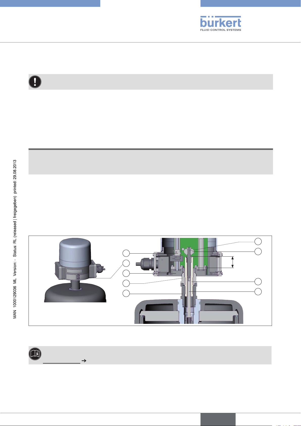
Setting stroke limit - for actuator sizes 175 and 225 mm
in combination with electrical feedback indicator type 8631
Follow the instructions in the relevant operating instructions for the devices.
Procedure:
Loosen grub screw Pos. 1 and remove control head Pos. 2.
→
Using a flat-blade screwdriver, screw Pos. 3 and 4 out of the lower part Pos. 8. →
Loosen lock nut Pos. 6. →
Note!
If the gap between the spindle and lock nut is too large, the device may be destroyed when the diaphragm is changed!
The gap between the flat surfaces of the spindle and the lock nut may be maximum 24 mm. •
Limit the maximum stroke by screwing in the spindle Pos. 5 using a wrench size 8 Allen key.
→
After setting the stroke, tighten the lock nut Pos. 6 and fasten the spindle Pos. 5. →
Screw in upper part of the switch spindle Pos. 3 and 4. →
Put on control head Pos. 2 and fasten in required position using grub screw Pos. 1 and set both limit switches →
(e.g. Pos. 9).
9
1
2
6
7
3
4
24
5
8
Setting stroke limitFig. 1:
The operating instructions and data sheets for the particular device can be found on the Internet at:
www.burkert.com
Supplement 1001/00_EU-ML_00805804 / Original DE
Page 2

Type 8631
Dokumentation
deutsch
Montageinformation - Hubbegrenzung einstellen
Hubbegrenzung einstellen -
für Antriebsgrößen 175 und 225 mm
in Kombination mit elektrischem Rückmelder Typ 8631
Beachten Sie die Hinweise in der jeweiligen Bedienungsanleitung der Geräte.
Vorgehensweise:
Madenschraube Pos. 1 lösen und Steuerkopf Pos. 2 entfernen.
→
Mit Hilfe eines Schlitzschraubendrehers Pos. 3 und 4 aus dem Unterteil Pos. 8 schrauben. →
Kontermutter Pos. 6 lösen. →
HiNweis!
Ein zu großer Abstand zwischen Spindel und Kontermutter kann bei Membranwechsel zur Zerstörung
des Gerätes führen!
Der Abstand zwischen den Planflächen der Spindel und der Kontermutter darf maximal 24 mm betragen. •
Den Maximalhub durch Einschrauben der Spindel Pos. 5 mit Hilfe eines Innensechskantschlüssels SW 8
→
begrenzen.
Nach Einstellung des Hubes die Kontermutter Pos. 6 anziehen und somit die Spindel Pos. 5 fixieren.
→
Oberteil der Schaltspindel Pos. 3 und 4 einschrauben. →
Steuerkopf Pos. 2 aufsetzen und mit Madenschraube Pos. 1 in gewünschter Position fixieren und die beiden →
Endschalter (z. B. Pos. 9) einstellen.
3
9
1
2
6
7
24
4
5
8
Hubbegrenzung einstellenBild 1:
Bedienungsanleitungen und Datenblätter zum jeweiligen Gerät finden Sie im Internet unter:
www.buerkert.de
Supplement 1001/00_EU-ML_00805804 / Original DE
Page 3

Type 8631
Fiches Techniques
français
Informations pour le montage - Régler la limitation de course
Régler la limitation de course -
pour les tailles d‘actionneur de 175 et 225 mm
en association avec un indicateur électrique de position
type 8631
Veuillez observer les remarques des instructions de service respectives des appareils.
Procédure à suivre :
Desserrer la vis sans tête pos. 1 et retirer la tête de commande pos. 2.
→
A l‘aide d‘un tournevis à empreinte cruciforme, dévisser les pos. 3 et 4 de la partie inférieure pos. 8. →
Desserrer le contre-écrou pos. 6. →
RemaRque !
Une distance trop importante entre la broche et le contre-écrou peut entraîner la destruction de
l'appareil lors du remplacement de la membrane !
La distance entre les surfaces planes de la broche et le contre-écrou doit être de 24 mm au maximum. •
Limiter la course maximale par vissage de la broche pos. 5 à l‘aide d‘une clé à six pans creux de 8.
→
Après réglage de la course, serrer le contre-écrou pos. 6 et fixer ainsi la broche pos. 5. →
Visser la partie supérieure de la broche de commande pos. 3 et 4. →
Mettre la tête de commande pos. 2 en place, la fixer dans la position souhaitée avec la vis sans tête pos. 1 et →
régler les deux fins de course (par ex. pos. 9).
9
1
2
6
7
24
3
4
5
8
Régler la limitation de courseFig. 1 :
Vous trouverez les instructions de service et les fiches techniques concernant l'appareil respectif sur Internet
sous :
www.buerkert.fr
Supplement 1001/00_EU-ML_00805804 / Original DE
 Loading...