

Page 1
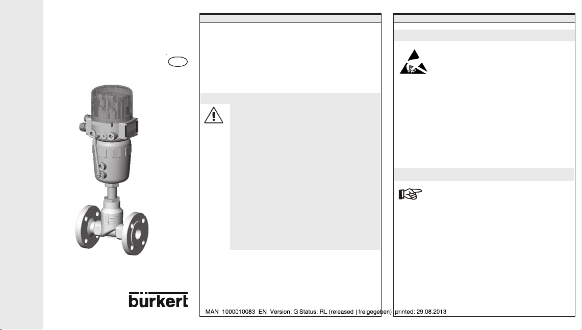
Control valve with
g
e
u
s
c
e
n
o
e
u
r
n
TOP
Control
Quickstart
Installation and Operation
Continuous
GB
Fluid Control Systems
GENERAL INFORMATION
Described in these instructions by way of example, is the
commissioning of a single-acting control valve without field
bus communication.
You will find the detailed description of the device in the
operating instructions for the TOP
8630 also in the operating instructions for the process valves
on the supplied CD.
Control
Continuous Type
Safety instructions
• Comply with the generally recognised rules of
practice for the application planning and
operation of the device!
• Installation and maintenance work is only to be
carried out by suitably trained tradesmen using
appropriate tools and equipment!
• Comply with the applicable accident prevention
and safety regulations for electrical equipment
during operation and maintenance work on the
device!
• Always switch off the voltage supply prior to any
interventions to the system!
• Remember that pipelines and valves in systems
which are under pressure must not be opened!
• Take appropriate steps to rule out inadvertent
actuation or unacceptable maltreatment!
• Guarantee a defined and controlled system
restart following an interruption to the electrical or
pneumatic supply!
GENERAL INFORMATION TECHNIC
Safety instructions
ATTENTION EXERCISE CAUTION WHEN
The device contains electronic components which react
sensitively to an electrostatic discharge (ESD). Contact with
electrostatically charged persons or objects will damage these
components. In the worst case they are immediately destroyed
or will fail after commissioning.
Comply with the requirements according to EN 100 015 – 1 in
order to minimise or eliminate the possibility of damage
through an abrupt electrostatic discharge. Take care also not
to touch electronic components when the supply voltage is
applied.
HANDLING!
ELECTROSTATICALLY ENDANGERED
COMPONENTS / ASSEMBLIES
Use for the intended purpose
Comply with the directions in these instructions, also the
operating conditions and permissible data according to
Datasheet Type 8630, to ensure that the device functions correctly and
remains serviceable throughout its life. In the event of noncompliance with these instructions, also of impermissible
interventions to the device, we waive all liability and the guarantee for
the device and all accessory parts is cancelled! The device is
intended exclusively for use as a positioning and process control
system. Any different use or use going beyond this is considered
improper use
use. The risk is carried solely by the user.
. Bürkert is not liable for damage resulting from such
Page 2

Technical data / possible extensions
Operating conditions
Ambient temperature 0 ... +50°C
Degree of protection IP 65 according to EN 60529
Electrical data
Voltage supply 24 V DC ± 10 %
Safety class 3 according to VDE 0580
Pneumatic data
Control medium Quality classes
- Dust content max. particle size 40 µm
- Water content max. pressure dew point -20°C
- Oil content max. 25mg/m
Temperature range
of compressed air
Pressure range 3 ... 7 bar
Fluctuation of supply
pressure
to DIN ISO 8573-1
max. particle density 10 mg/m
3
-10 ... +50°C
max. ± 10 % during operation
Possible extensions
• Analogue position check-back signal
• Inductive proximity switch
• Binary input / output
• Bus communication
• Software additional functions
We reserve the right to make technical changes without notice.
CONSTRUCTION AND FUNCTIONS
Overview
TOP
Control
Continuous
Actuator
FLUID CONNECTION ELECTRICAL CONNECTION
Control air connection
The fixing screw (connection between Top
and process valve) may only
be tightened with a
maximum torque of 1.2 Nm.
Control
Valve
According to the operating conditions, different process valves
from the Bürkert programme can be combined with the
TOP
Control
3
straight seat control valves, diaphragm or ball valves.
Functions
Position controller
Process controller (option)
Continuous. Suitable alternatives are slanted and
The position of the drive (stroke) is controlled
corresponding to the position set-point. The position setpoint can be predetermined by an external standard
signal.
The TOP
Control
The stroke of the valve is calculated from the process setpoint and the process actual value via the control
parameters (PID controller). The process set-point can be
predetermined by an external signal.
Continuous is combined in a control loop.
Connector 1
Supply pressure
3 ... 7 bar
Installing the valve
• Installation attitude optional; preferably as above.
• Take note of the flow direction; generally applicable for control
valves: Free-stream under seat!
• Make sure pipelines are free of all dirt and contamination!
• Make sure the pipelines are aligned before connecting the valve
housing.
• In the case of welded housings, be sure to remove the drive
before welding in the housing.
Connector 3:
Exhaust air silencer
Connector 2.2:
For double-acting drives
Connector 2.1: (mounted ex-works)
a) Action power-off closed (NC):
Actuator:
Actuator:
Bottom connector
Top connector
b) Action power-off open (NO):
Page 3

ELECTRICAL CONNECTION
Connections
2 possibilities
• Multipole connection
• Heavy-gauge threaded union
Signal values
• Supply voltage: 24 V D C
• Set-point (process/position controller): 0 ... 20 mA; 4 ... 20 mA
• Actual value (process controller only): 4 ... 20 mA;
* Process actual value (option process controller)
Only the possibility of signal value 4…20 mA is represented in
these instructions.
For connecting other kinds of signal: see
for TOP Control Continuous.
0 ... 5 V; 0 ... 10 V
frequency; PT100
Operating instructions
ELECTRICAL CONNECTION
Multipole connection
Connector
plug M16
(Set-point)
Pin A
Ground (-)
Pin B
0 ... 20 mA
4 ... 20 mA
0 ... 5 V
0 ... 10 V
C
L
B
4 ... 20 mA internally supplied
(jumper in place)
PIN 1 24 V input transmitter
PIN 2 output transmitter
PIN 3 GND
PIN 4 jumper to GND
Jumper
E
D
F
G
M
H
A
J
K
24
1
Connector plug M8
(Process actual value)*
Connector
plug M12
(Supply)
Pin 1
+ 24 V
Pin 3
Ground (-)
1
2
3
3
4 ... 20 mA externally supplied
(jumper not in place)
PIN 1 not assigned
PIN 2 process actual +
PIN 3 not assigned
PIN 4 process actual -
ELECTRICAL CONNECTION
Heavy-gauge threaded union
Terminal
1 Set-point + 0/4 ... 20 mA; 0 ... 5/10 V
2 Set-point - GND
5 Operating voltage + 24 V D C
6 Operating voltage - GND
4
Process actual value *
4 ... 20 mA internally supplied
(jumper 1 in place)
Terminal
7 24 V input transmitter
8 Output transmitter
9 Jumper to GND
10 GND
4 ... 20 mA externally supplied
(jumper 1 not in place)
Terminal
7 not assigned
8 Process actual +
9 Process actual 10 not assigned
Page 4

BRANCHES
n
p
i
g
a
Contact addresses / Kontaktadressen
Germany / Deutschland / Allemange
Bürkert Fluid Control System
Sales Centre
Chr.-Bürkert-Str. 13-17
D-74653 Ingelfingen
Tel. + 49 (0) 7940 - 10 91 111
Fax + 49 (0) 7940 - 10 91 448
E-mail: info@de.buerkert.com
International
Contact addresses can be found on the internet at:
Die Kontaktadressen finden Sie im Internet unter:
Les adresses se trouvent sur internet sous :
www.burkert.com Bürkert / Company / Locations
Chr.-Bürkert-Straße 13-17 Berlin Ph: (0 30) 67 97 17 - 0
74653 Ingelfingen Dortmund Ph: (0 23 73) 96 81 - 0
Ph: (0 79 40) 10-111 Frankfurt Ph: (0 61 03) 94 14 - 0
Fax (0 79 40) 10-448 Hannover Ph: (0 5 11) 9 02 76 - 0
www.buerkert.com München Ph: (0 89) 82 92 28 - 0
info@de.buerkert.com Stuttgart Ph: (07 11) 4 51 10 - 0
BÜRKERT INTERNATIONAL
A Ph. +43 (0)1-894 13 33 Fax +43 (0)1-894 13 00
AUS Ph. +61 1300 888 868 F ax +61 1300 888 076
B Ph. +32 (0)3-325 89 00 Fax +32 (0)3-325 61 61
BRA Ph. +55 (0)11-5182 0011 Fax +55 (0)11-5182 8899
CDN Ph. +1 905-847 55 66 Fax +1 905-847 90 06
CH Ph. +41 (0)41-785 66 66 Fax +41 (0)41-785 66 33
CN Ph. +86 21-5868 21 19 Fax +86 21-5868 21 20
CZ Ph. +420 543-25 25 05 Fax +420 543-25 25 06
DK Ph. +45 44-50 75 00 Fax +44-50 75 75
ES Ph. +34 93-477 79 80 Fax +34 93-477 79 81
EE Ph. +372 6440 698 Fax +372 6313 759
FI Ph. +358 (0)207 412 550 Fa x +358 (0)207 412 555
FR Ph. +33 (0)388-58 91 11 Fax +33(0)388-57 20 08
HKG Ph. +852 248 012 02 Fa x +852 241 819 45
IT Ph. +39 02-959 071 Fax +39 02-959 07 251
IND Ph. +91 (0)44-4230 3456 Fa x +91 (0)44-4230 3232
J Ph. +81 (0)3-5827-0066 Fax +81 (0)3-5827-0067
KOR Ph. +82 (0)2-3462 5592 Fa x +82 (0)2-3462 5594
NO Ph. +47 63-84 44 10 F ax +47 63-84 44 55
NL Ph. +31 (0)346-58 10 10 Fax +31 (0)346-56 37 17
NZ Ph. +64 (0)9-622 28 40 F ax +64 (0)9-622 28 47
P Ph. +351 212 898 275 Fa x +351 212 898 276
PL Ph. +48 (0)22-840 60 10 Fax +48 (0)22-840 60 11
RC Ph. +886 (0)2-2653 78 68 Fa x +886 (0)2-2653 7968
RP Ph. +63 (0)2-776 43 84 Fax +63 (0)2-776 43 82
SE Ph. +46 (0)40-664 51 00 Fax +46 (0)40-664 51 01
SA Ph. +27 (0)11-574 60 00 Fax +27 (0)11-454 14 77
SIN Ph. +65 6844 2233 F ax +65 6844 3532
TR Ph. +90 (0)232-459 53 95 F ax +90 (0)232-459 76 94
TT Ph. +60 (0)4-643 5008 Fax +60 (0)4-643 7010
UK Ph. +44 (0)1453-73 13 53 Fa x +44 (0)1453-73 13 43
USA Ph. +1 949-223 31 00 Fax +1 949-223 31 98
Operating Instructions 0606/07_EU-EN_00804460
OPERATING
SETTINGS ON COMMISSIONING SETTIN
Display and keyboard Menu structure
MANUAL/AUTOMAIC key
Arrow keyupArrow key
Arrow key
up
• Scrolling within a level
• Changing parameters
Arrow key
down
• Scrolling within a level
• Changing parameters
MANUAL/AUTOMATIC key
• Level 1: Changing over between manual and automatic mode
• Level 2: Confirming a parameter
• Level 3: Selecting a menu point
(see also
Menu structure
LED (yellow)
• Indication of operating mode
• AUTOMATIC LED flashes
• MANUAL LED off
LED (yellow)
down
in the MANUAL/A/TOMATIC key
)
(RETURN)
Page 5

Indications in AUTOMATIC mode (level 1)
Display / Indication
Position controller Process controller
POS:
Actual position valve
CMD:
Set positio n valve
INP:
Input signal for set
position
Te mp :
Device internal
temperature
PV:
Process actual value
SP:
Process set-point
POS:
Actual position of
valve
CMD:
Set position of valve
Te mp :
Device internal
temperatur e
Inverted comma moves from left to right.
Changing to configuration mode (Level 2)
Keep key pressed for 5 seconds.
SETTINGS ON COMMISSIONING
Setting the type of action of the servo drive
Select the function
Select
FUNCSNGL
FUNCDOUB
The type of action is shown on the rating plate.
ACT FUNC
ACT FUNC
with the key.
for a drive with spring return. Select
for a double-acting drive.
FUNCSNGL
FUNCDOUB
single-acting
double-acting
Input of the type of signal for external set-point
preselection
Set the function
INPUT
INPUT
with the key.
INP 4’20A
INP 0’20A
INP 0’10V
INP 0’5V
Current 4 ... 20 mA
Current 0 ... 20 mA
Voltage 0...10 V
Voltage 0 ... 5 V
SETTINGS ON COMMISSIONING SETTINGS ON COMMISSIONING
Starting the
You start
parametrizing of the TOP
function
Select the function
X.ERR X
AUTOTUNE
AUTOTUNE
X.TUNE.
X.TUNE
- Indication on the occurrence of an error
No parametrizing of the process controller takes place through the
AUTOTUNE
function.
function
, the program for the automatic
Control
Continuous by calling the
X.TUNE
with the key.
- Countdown from 5 to 0
TUNE X
TUNE END
- Indication of the currently
runing
AUTOTUNE
phase.
End of the
phase.
AUTOTUNE
Activating the process control (option) - Level 3
Select
ADDFUNC
key and access the 3rd level.
Select
key and obtain the function *
Select
with the key, confirm the selection with the
P.CONTRL
with the key, confirm the selection with the
P.CONTRL
..
END
with the key, confirm the selection with the key.
Page 6

SETTINGS ON COMMISSIONING SETTINGS ON COMMISSIONING SETTINGS ON COMMISSIONING
Setting up the process control (option) - Level 2
The function
be parametrized there as follows:
Select
P.CONTRL
P.CONTRL.
has been shifted to the 2nd level and can
with the key.
P. CO DB ND
P. CO PA R A
P. CO SE T P
P. CO IN P
P. CO FI LT
P.CO PARA
Input of the PID
controller
parameters
Kp, Tn, Tv u. X0
(operating point)
P.CO INP
Type of signal of
the process
actual value
preselection
P. CO SC A L
P. C O TU N E
P. CO EN D
COUNT:
Each individual place:
increment,
decrement.
Confirm total
value, also each
individual place:
MANUAL or AUTOMATIC mode
In the 1st level you can change over between the MANUAL and the
AUTOMATIC mode by pressing the .
Opeerating
mode
AUTO MATIC f las hes
MANUAL off
Functions
Yellow LED Display
Inverted comma moves from left
to right (for further indic ations see
Indications in AUTOMATC-mode)
The last indication set in
AUMTOMATIC mode is displayed.
MANUAL mode AUTOMATIC mode
Opening the valve The valve regulates
Closing the valve
Hold the up key pressed and
simultaneously pres s the down key:
Opening in rapi d speed
Hold the down key pressed and
simultaneously pres s the up key:
Closing in rapid speed
according to the
set-point
preselection.
Changing the internal set-point
(process controller only)
In AUTOMATIC mode:
Press the key or key for 3 seconds.
Set the process set-point with the key or key.
Confirm the entry with the key and return to the operating mode.
These and all other software functions are
described in detail in the operating instructions for
the TOP
Control
the supplied CD).
Continuous Type 8630 (on
Exiting the CONFIGURATION MODE
Select the function
Confirm the selection with the key.
Changeover to the operating mode takes place.
END
with the key.
 Loading...