

Page 1

Multi-Function Machine
SERVICE MANUAL
MODEL: MFC6800/DCP1000
MFC9180/MFC9160
Page 2

© Copyright Brother 2001
All rights reserved.
No part of this publication may be reproduced in any
form or by any means without permission in writing
from the publisher.
Specifications are subject to change without notice.
Page 3

PREFACE
This publication is a Service Manual covering the specifications, construction, theory of operation,
and maintenance of the Brother multi-function machine. It includes information required for field
troubleshooting and repair--disassembly, reassembly, and lubrication--so that service personnel
will be able to understand machine function, to rapidly repair the machine and order any necessary
spare parts.
To perform appropriate maintenance so that the machine is always in best condition for the
customer, the service personnel must adequately understand and apply this manual.
This manual is made up of six chapters and appendices.
CHAPTER 1 GENERAL DESCRIPTION
CHAPTER 2 INSTALLATION
CHAPTER 3 THEORY OF OPERATION
CHAPTER 4 DISASSEMBLY/REASSEMBLY AND LUBRICATION
CHAPTER 5 MAINTENANCE MODE
CHAPTER 6 ERROR INDICATION AND TROUBLESHOOTING
Appendix 1. EEPROM Customizing Codes
Appendix 2. Firmware Switches (WSW)
Appendix 3. Circuit Diagrams
This manual describes the models and their versions to be destined for major countries. The specifications
and functions are subject to change depending upon each destination.
Page 4

SAFETY INFORMATION
Laser Safety (110-120V Model only)
This printer is certified as a Class 1 laser product under the US Department of Health and Human
Services (DHHS) Radiation Performance Standard according to the Radiation Control for Health
and Safety Act of 1968. This means that the printer does not produce hazardous laser radiation.
Since radiation emitted inside the printer is completely confined within the protective housings and
external covers, the laser beam cannot escape from the machine during any phase of user
operation.
CDRH Regulations (110-120V Model only)
The Center for Device and Radiological Health (CDRH) of the US Food and Drug Administration
implemented regulations for laser products on August 2, 1976. These regulations apply to laser
products manufactured from August 1, 1976. Compliance is mandatory for products marketed in
the United States. The label shown below indicates compliance with the CDRH regulations and
must be attached to laser products marketed in the United States.
The label for Chinese products
MANUFACTURED: JUNE 2001 C
BROTHER CORP. (ASIA) LTD.
BROTHER BUJI NAN LING FACTORY
Gold Garden Industry, Nan Ling Village, Buji,
Rong Gang, Shenzhen, China.
This product complies with FDA radiation
performance standards, 21 CFR Subchapter J.
Page 5

CHAPTER
GENERAL DESCRIPTION
1
Page 6

CHAPTER 1 GENERAL DESCRIPTION
CONTENTS
1.1 OUTLINE..........................................................................................................................1-1
1.1.1 External Appearance and Weight ........................................................................1-1
1.1.2 Components ......................................................................................................... 1-1
1.2 SPECIFICATIONS............................................................................................................1-2
Page 7
1.1 OUTLINE
m
m
1.1.1 External Appearance and Weight
The figure below shows the machine appearance and approximate dimensions.
(H) 354 mm
13.9"
(D) 458 m
18.0"
Weight: Machine proper Approx. 11 kg
Machine (incl. drum unit & toner cartridge) Approx. 12 kg
In package Approx. 16 kg
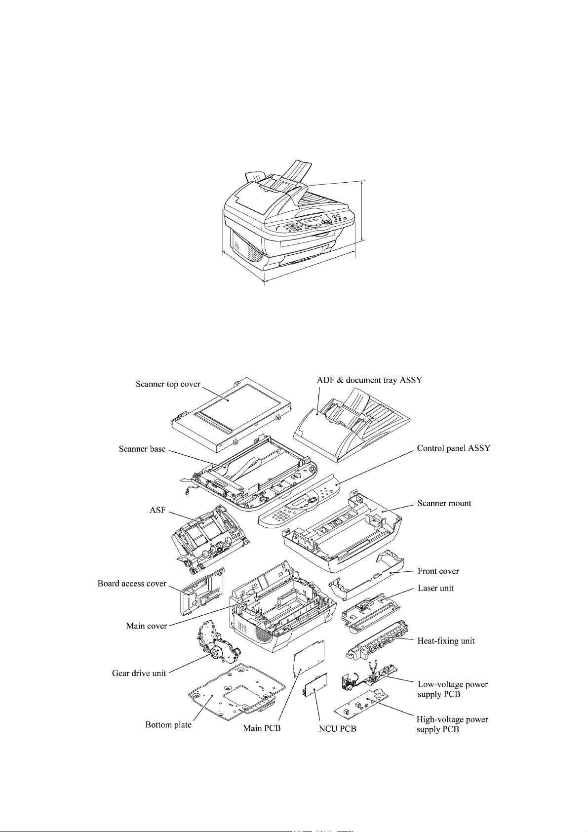
1.1.2 Components
The machine consists of the following major components:
(W) 459 m
18.1"
1-1
Page 8

1.2 SPECIFICATIONS
g
)
)
)
)
p
)
)
p
g
R
p
p
A
)
ght
p
)
)
)
)
)
y
(
)
(
)
g
g
g
g
g
r
g
y
p
)
p
App
App
p
p
g
g
ging
g
y
g
p
)
)
g (
)
)
X
X
A
y
p
)
App
y
)
)
y
)
)
g
)
p
)
)
p
)
)
A
(
)
p
)
y
y
y
p
(
)
(
)
A
)
p
(
)
(
)
(
)
A
AN/A
A
AN/A
Model Name MFC 6800 DCP 1000
GENERAL
ine Laser (YL4
Print En
Modem Speed (bps
Transmission S
ITU-T Grou
Codin
ut/Output Widt h 5.8"-8.5"/3.5"- 8.5" 5.8"-8.5"/3.5" -8.5"
In
In
ut/Output Length 5"-14"/5"-14" 5"-14"/5"-14"
DF (pages
LCD Size 16 characters x 2 lines 16 characters x 2 lines
LCD Backli
Backu
Memory Capacity (physical
Optional Memor
Dimensions w/ Carton
Dimensions w/o Carton
ht w/ Carton 16 k
Wei
Weight w/o Carton 11 k
Colo
Operatin
Humidit
Power Source 120 VAC 50/60Hz 120 VAC 50/60Hz
Power Consum
On/Off Switch Yes Yes
Warm U
TELEPHONE
Handset No One-Touch Dial No -
eed Dial 100 -
S
eaker Phone No -
S
Chain Dialin
Caller ID Yes Call Waitin
Distinctive Rin
Call Mana
Hold/Mute Ke
Power Failure Dialin
eaker (Volume
S
Rin
Volume
Handset Volume - PBX Feature No Transfer Method No -
FA
Internet FA
Eas
Receive/Fax Detect Yes Fax/Tel Switch - Enhanced Remote Activate Yes Scan S
Memor
Memor
Broadcastin
Manual Broadcasting
Out-of-Pa
Out-of-Pa
uto Reduction Yes ECM
Grou
Memor
Memor
Color FAX
Color FAX
LIST/REPORT
ctivity Report/Journal Report Yes (up to 200
Transmission Verification Re
INTERFACE
External TAD Interface Yes No
Host Interface
Host Interface
Host Interface
LAN Interface No No
cceptable Media Card Slot
nalog Video Port
eed (sec.
Method MH/MR/ MM
Clock Yes (1 hour
WxDxH
WxDxH
Environment Temperature 10 - 32.5 degrees Centigrade 10 - 32.5 degrees Centigrade
tion (Sleep/Standby/Peak
Time
Caller I D No -
eNo-
eed (sec./page, A4:Standard
Transmission (Brother#1 Chart
Transmission (ITU-T Chart
er Reception (Brother #1 Chart
er Reception (ITU-T Chart
Error Correction Mode
Dial Yes (up to 6
Securit
Backu
Document Send/Receive
Memory Send/Recei ve
ort Yes -
Serial
IEEE1284
USB
500 pages (MMR/Standard Resolution
400 pages (MMR/Standard Resolution
500 pages (MMR/Standard Resolution
400 pages (MMR/Standard Resolution
YL4-FB(MFC) YL4-DCP
14,400 (Fax
6 (Brother#1,MMR
G3 -
Up to 30 Up to 30
No No
8 Mbytes (RAM
No No
596 x 566 x 452 mm 596 x 566 x 452 mm
459 x 458 x 354 mm 459 x 458 x 354 mm
Gray 1495 Gray 1495
20 - 80% 20 - 80%
15W/ 75W/ 940W or less 15W/ 75W/ 940W or less
rox. 13 sec.
Yes -
Yes -
No -
No Yes (3 steps + OFF
Yes (3 steps + OFF
N/
rox. 3 -
Yes (150 locations
Yes -
Yes -
No -
No No
No -
No -
No No
Yes Yes
Yes Yes
N/
N/
Laser (YL4
-
-
-
Yes (1 hour
8 Mbytes (RAM
16 k
11 k
rox. 13 sec.
-
-
-
-
-
-
-
-
-
-
(1/2)
1-2
Page 9

Model Name MFC 6800 DCP 1000
g
)
)
)
p
(ppm)
p
)
A
)
p
)
guag
p
AN/A
p
r
r
g
(
)
(
)
AN/A
r
/
/
p
)
py (
)
py (
)
y)
y)
)
(dpi)
py
)
App
App
(
)
App
App
r
r
)
)
)
)
y
(
)
)
/
pp
r
r
R
x
y)
A
p
A
y)
A
y)
pp
r
r
r
R
x
p
pag
g
g
g
PRINTER
Color/Mono Mono Mono
En
ine Type Laser (YL4
Resoluti on (dpi
S
eed
Pa
er Capacity (sheets
dditional Paper Capacity (sheets
Out
ut Paper Capacity (sheets
Standard Print Lan
Emulation No No
Resident Fonts No No
Fonts Disk Based Yes Yes
er Handling Size LTR, LGL, A4, B5, A5, EXE LTR, LGL, A4, B5, A5, EXE
Pa
Manual Feed Slot N/
Other Paper TypeOHP, Envelo
Sheet Weight (Paper Tray)
Printer Drive
COPY
Color/Mono Mono Mono
S
eed (cpm
Mult i Co
Mult i Co
Reduction/Enlargement (%
Resoluti on
First Co
SCANNER
Color/Mono Colo
Resoluti on(Optical : dpi
Resoluti on(Int. : dpi
Gra
Color Depth
TWAIN Compliant&Operating System Win95/98/98SE/Me, WinNT4.0WS
PCI Scanner (Parallel/Serial)
BUNDLED SOFTWARE
For Windows
Su
Printer Drive
TWAIN Yes Yes
Viewe
PC Fa
Remote Setu
PC Diagnostics Yes
Others
For iMac/G3/G4
Su
TWAIN MacOS 8.6-9.1 MacOS 8.6-9.1
Printer Drive
TWAIN Yes Yes
Viewe
PC Fa
Remote Setu
PC Diagnostics
Others - -
ACCESSORY
Life / Yield Starter: 2,200
Toner : TN-250 Re
Drum : DR-250 20,000 pa
Stack
Sort
Out Time (From Ready Mode/ADF
Scale 256 256
ort OS version
ort OS version Printer Drive
e Windows GDI Windows GDI
Manual Slot
Win95/98/98SE/Me/2000Professional
From Ready Mode/FB
Win95/9 8/98SE/Me, WinNT4.0WS/2000Professional Win95/98/98SE/Me, W inNT4.0W S/2000Professi onal
Pop Up Menu Yes Yes
OC
uto E-mail Printing(Win 95/98(SE)/Me onl
Pop Up Menu
OC
YL4-FB(MFC) YL4-DCP
600 x 600 600 x 600
up to 10 up to 10
200 200
No No
50 50
es, Organize
2
/m
64-158
NT4.0WS MacOS 8.5.1-9.1 NT4.0WS MacOS 8.5.1-9.1
25 -- 400 in 1% increments 25 -- 400 in 1% increments
600x300 (Max. 600x2,400
2000Profess ional, MacOS 8.6-9.1 2000Professional, MacOS 8.6-9.1
Yes(TX:FAX Share onl
ular:2,200 pages @5% coverageRe
8,000 pages @5% cvrg: 1 page/job 8,000 pages @5% cvrg: 1 page/job
16 - 42 lb
N/
Up to 10 Up to 10
Yes Yes
Yes (ADF onl
300 x 300 300 x 300
rox. 13 sec.
rox. 12 sec.
9,600x9,600 9,600x9,600
24 bit
8 bits x 3
Parallel/USB Parallel/USB
Yes Yes
Yes Yes
Yes Yes
Yes No
MacOS 8.5.1-9.1 MacOS 8.5.1-9.1
Yes Yes
Yes Yes
No No
Yes Yes
Yes No
No No
No No
es @5% coverage Stater: 2,200 pages @5% coverage
es @5% cvrg: 20 pages/job 20,000 pages @5% cvrg: 20 pages/job
Win95/98/98SE/Me/2000Professional
Win95/98/98SE/Me, WinNT4.0WS/
uto E-mail Printing(Win 95/98(SE)/Me onl
Laser (YL4
OHP, Envelopes, Organize
64-158 g/m2 (16 - 42 lb)
Yes (ADF onl
rox. 13 sec.
rox. 12 sec.
600x300 (Max. 600x2,400
ular:2,200 pages @5% coverage
Colo
24 bit (8 bits x 3
N/
No
(2/2)
1-3
Page 10
g
)
)
)
)
p
)
App
)
p
g
R
p
p
p
)Up
)
g
p
)
)
)
)
)
y
AN/A
)
(
)
g
g
g
g
g
r
p
y
p
)
p
App
App
p
p
g
A
g
A
ging
(
y)
g
y
A
g
A
p
)
g
)
A
X
X
A
y
(
)
)
y
pag
y
)
)
g
g
p
pag
)
p
)
)
A
(
)
p
)
y
y
y
p
)
(
)
(
)
A
)
p
(
)
(
)
(
)
A
AN/A
A
AN/A
Model Name
GENERAL
ine Laser (YL4
Print En
Modem Speed(bps
Transmissi on S
ITU-T Grou
Codin
ut/Output Widt h 5.8"-8.5"/3.5"-8.5" 5.8"-8.5"/3.5"-8.5"
In
In
ut/Output Length 5"-14"/5"-14" 5"-14"/5"-14"
ADF(pages)
LCD size 16 characters x 2 lines 16 characters x 2 lines
LCD Backli
Backu
Memory Capacity (physical
Optional Memor
Dimensions w/ Carton (WxDxH
Dimensions w/o Carton
Wei
ht w/ Carton 16 k
Weight w/o Carton 11 k
Colo
erating Environment Temperature 10 - 32.5 degrees Centigrade 10 - 32.5 degrees Centigrade
O
Humidit
Power Source 22 0-240 VAC 50/60 Hz 220-240 VAC 50/60Hz
Power Consum
On/Of f Swi tch Yes Yes
Warm U
TELEPHONE N/A
Handset No One-Touch Dial No S
eed Dial 100 -
S
eaker Phone No Chain Dialin
Caller ID N/
Call Waitin
Distinctive Rin
Call Mana
Hold/Mute ke
Power Failure Dialin
S
eaker Volume Yes (3 steps + OFF
Rin
Volume Yes (3 steps + OFF
Handset Volume N/
PBX Feature Yes Transfer Method Flash -
FA
Internet FA
Eas
Receive/Fax Detect Yes Fax/Tel Switch Yes Enhanced Remote Activate Yes Quick Scan
Memor
Memor
Broadcastin
Manual Broadcastin
Out-of-Pa
Out-of-Pa
uto Reduction Yes -
Error Correcti on Mode
ECM
Grou
Memor
Memor
Color FAX
Color FAX
LIST/REPORT
ctivity Report/Journal Report Yes (up to 200
Transmissi on Verifi cation Re
INTERFACE
External TAD Interface Yes No
Host Interface
Host Interface
Host Interface
LAN Interface No No
cceptable Media Card Slot
nalog Video Port
eed(sec.
Method MH/ MR/MM
ht Yes Yes
Clock Yes (9 hours
WxDxH
tion (Sleep/Standby/Peak
Time
Caller ID N/
Yes
eNo-
Memory transmission
Transmission (ITU-T #1 Chart) 400
Transmission (Brother#1 Chart
er Reception (ITU-T #1 Chart) 400
er Reception (Brother#1 Chart
Dial Yes (up to 6
Securit
Backu
Document Send/Receive
Memory Send/Receive
ort Yes -
Serial
IEEE1284
USB
Yes as defaul t. Approx.2.8 sec/page (A4 standar d
YL4-FB(w/ Modem) YL4-FB(w/o Modem)
MFC-9180 MFC-9160
14,400 (Fax
rox. 6 (brother #1chart,MMR
15W/ 75W/ 940W or less 15W/ 75W / 940W or less
500 pages (MMR/Standard Resolution
500 pages (MMR/Standard Resolution
G3 -
U
to 30 (75 g/m
8 Mbytes (RAM
596 x 566 x 452 mm 596 x 566 x 452 mm
459 x 458 x 354 mm 459 x 458 x 354 mm
Gray 1495 Gray 1495
20 - 80 % 20 - 80 %
rox. 12 sec.
UK.DEN onl
es (MMR/Standard Resolution) -
Yes ( 150 locations) -
Yes (50 locations ) -
es (MMR/Standard Resolution
Yes ( Max. 4 days
No / No No / No -
2
N/
Yes -
N/
N/
N/
Yes -
Yes -
No No
Yes Yes
Yes Yes
N/
N/
Laser (YL4
-
-
-
to 30 (75 g/m
Yes (1 hour
8 Mbytes (RAM
16 k
11 k
rox. 12 sec.
-
-
-
-
-
-
-
-
N/A
-
-
-
-
-
-
-
-
2
(1/2)
1-4
Page 11

g
)
)
)
p
(ppm)
(
)
)
A
)
p
)
guag
(
)
)
)
p
AN/A
p
r
r
g
(
g
(
)
AN/A
r
p
)
py (
)
py (
)
(
g
)
(dpi)
py
)
App
App
(
)
App
App
(Op
)
(
)
y
(
)
)
(
)
pp
r
r
p Up
R
x
p
pp
r
r
p Up
R
x
p
A
A
g
pag
Model Name
PRINTER
YL4-FB(w/ Modem) YL4-FB(w/o Modem)
MFC-9180 MFC-9160
Color/Mo no Mono Mono
En
ine Type Laser (YL4
Resolution (dpi
S
eed
Paper Capacity (sheets)
dditional Paper Capacity (sheets
Out
ut Paper Capacity (sheets
Standard Print Lan
Emulation Yes
Resident Fonts
e Windows GDI Windows GDI
Yes ( Bitmap font: LetterGothic16.66, OCR-A,
OCR-B, Scalable font: 49 fonts
600 x 600 600 x 600
200
up to 10 up to 10
2
75 g/m
No No
50 50
PCL5e
Yes ( Bitmap font: LetterGothic16.66, OCR-A,
Laser (YL4
200 (75 g/m
2
Yes (PCL5e
OCR-B, Scalable font: 49 fonts )
Fonts Disk Based Yes Yes
er Handling Size LTR, LGL, A4, A5, EXE, A6, ISO B5, ISO B6 LTR, LGL, A4, A5, EXE, A6, ISO B5, ISO B6
Pa
Manual Feed Slot N/
Other Paper TypeOHP, Envelo
Sheet Weight (Paper Tray)
Manual Slot
Printer Drive
Win95/98(SE)/Me/NT4.0WS/2000 professional Win95/98(SE)/Me/NT4.0WS/2000 professional
64-158
es, Organize
2
/m
16 - 42 lb) 64-158
OHP, Envelopes, Organize
/m2 (16 - 42 lb)
N/
COPY
Color/Mo no Mono Mono
eed (cpm
S
Multi Co
Multi Co
Reduction/Enlar
Stack
Sort
ement (%
Resolution
Out Time (From Ready Mode/ADF
First Co
From Ready Mode/FB
Up to 10 Up to 10
Yes Yes
Yes (on ADF only ) Yes
25 to 400 in 1% increments 25 to 400 in 1% increments
on ADF only )
300 x 300 (print) 300 x 300 (print)
rox. 13 sec.
rox. 12 sec.
rox. 13 sec.
rox. 12 sec.
SCANNER
Color/Mono Color/Mono Color/Mono
Resolution
Resolution
Gra
Color Depth
TWAIN Compliant&Operating System Win95/98(SE)/Me/NT4.0WS/ 2000Professional Win95/ 98(SE)/Me/NT4.0WS/2000Professional
PCI Scanner (Parallel/Serial)
BUNDLED SOFTWARE
For Windows
Su
Printer Drive
TWAIN Yes Yes
Viewe
Po
OC
PC Fa
Remote Setu
PC Diagnostics
tical: dpi
Int.: dpi
Scale 256 256
600 x 2,400 600 x 2,400
9,600 x 9,600 9,600 x 9,600
24 bits
8 bits x 3
24 bits (8 bits x 3
MacOS 8.6-9.1 MacOS 8.6-9.1
Parallel/USB Parallel/USB
For Windows
ort OS version
Win95/9 8/98SE/Me, WinNT4. 0WS/2000Profrs sional Wi n95/98/ 98SE/Me, WinNT4.0W S/2000Profrssional
Yes Yes
Yes Yes
Menu Yes Yes
Yes Yes
Yes No
Yes No
Yes Yes
Others No No
For iMac/G3/G4
ort OS version Print MacOS8.5.1-9.1 MacOS8.5.1-9.1
Su
Others MacOS8.6-9.1 MacOS8.6-9.1
Printer Drive
TWAIN Yes Yes
Viewe
Po
Menu No No
OC
PC Fa
Remote Setu
PC Diagnostics
Yes Yes
No No
No No
Yes No
No No
No No
Others No No
ACCESSORY
Life / Yield Starter: N/
Toner:TN-8000 Regular:2,200 pages @5% coverageRe
Starter: N/
ular:2,200 pages @5% coverage
Drum:DR-8000 20,000 pages @5% cvrg: Continuous printi ng 20,000 pages @5% cvrg: Continuous printing
es @5% cvrg: 1 page/job 8,000 pages @5% cvrg: 1 page/job
8,000
(2/2)
1-5
Page 12

CHAPTER
INSTALLATION
2
Page 13

CHAPTER 2 INSTALLATION
CONTENTS
2.1 INSTALLING THE UPDATE DATA TO THE FACSIMILE MACHINE.............................2-1
2.2 SETTING ID CODES TO FACSIMILE MACHINES.........................................................2-3
Page 14
2.1 INSTALLING THE UPDATE DATA TO THE
r
FACSIMILE MACHINE
If the program version is updated or the main PCB is replaced, then install the update program
onto the flash ROM of the main PCB.
The program installation requires a PC/AT-compatible computer (which is capable of running MSDOS or its compatible OS).
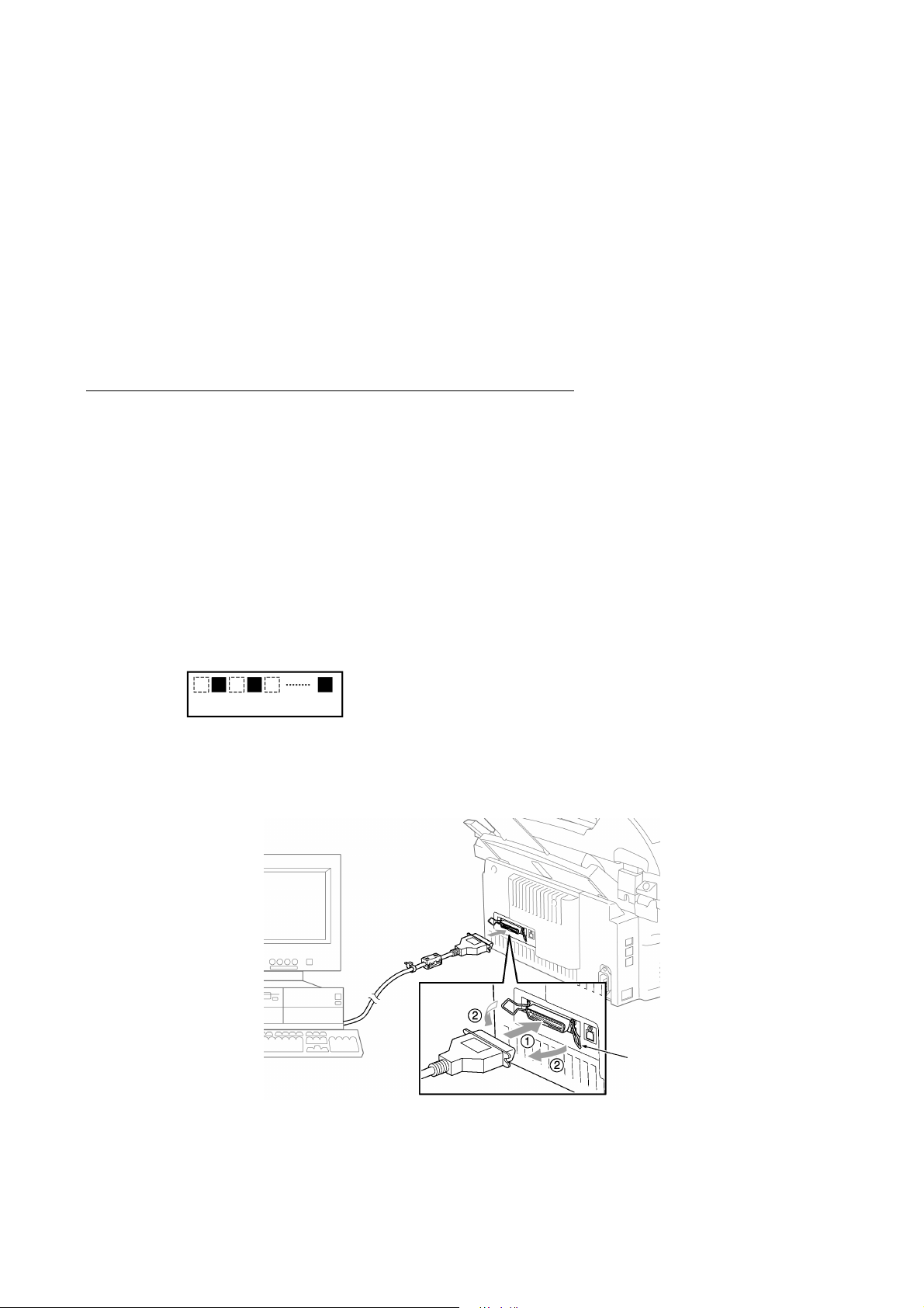
Connecting the facsimile machine to your computer
(1) Make sure that your computer is turned off.
(2) Make sure that the machine's power cord is unplugged from a wall socket. (If the machine has
a power ON/OFF switch, make sure that the switch is turned off.)
(3) Connect the parallel interface cable to the parallel port on the back of the machine and secure
it with the lock wires.
(4) Connect the other end of the interface cable to the printer port of your computer and secure it
with the two screws.
(5) While pressing the 5 key on the machine's control panel, plug the machine's power cord into a
wall socket (or turn on the power ON/OFF switch if the machine has the switch).
(6) Check to see that the following pattern displays on the LCD. If it does not display, go back to
step (2) above.
← 1st row: Blank-and-black patterns
← 2nd row: Blank
(7) Turn on your computer.
Parallel interface
cable
Host compute
Lock wires
2-1
Page 15

Installing the update data onto the flash ROM of the facsimile machine
NOTE: The following is an installation procedure example on a PC that is running Windows 95/98.
(1) Copy the update data and transfer utility onto the desired directory of the hard disk.
e.g., C:\UPDATE
(2) Click the Start button, point to Programs, and then click MS-DOS Prompt to open an MS-DOS
window.
(3) Type the drive letter where the update data and transfer utility are located. In the above
example, type C:\ from the command line and press the ENTER key.
Then type CD UPDATE and press the ENTER key.
(4) Check that your computer is connected with the facsimile machine correctly.
(5) To start the transfer utility transmitting the update data to the flash ROM of the facsimile
machine, type the following:
ICEN filename /b
Then press the ENTER key.
During downloading, the machine beeps intermittently.
Upon completion of the downloading, the machine beeps continuously.
NOTE: If the facsimile machine cannot return to the standby state after completion of downloading,
turn the power off and on.
2-2
Page 16

2.2 SETTING ID CODES TO FACSIMILE MACHINES
Function
Brother facsimile machines are assigned unique ID codes (character strings) at the factory. If you
replace the main PCB of the machine, the machine will lose its assigned ID code so that it will not
be identified by the connected PC*.
You need to assign a unique ID code (character string) to the machine according to the procedure
given here. For models covered by this manual, set serial numbers given to individual machines as
ID codes.
(*ID codes are essential when more than one machine is connected to a single PC via USB.)
Connecting each of facsimile machines to your PC
(1) Make sure that your PC is turned off.
(2) Make sure that the machine's power cord is unplugged from a wall socket or other power
source.
(3) Connect the interface cable to the parallel interface port on the back of the facsimile machine
and secure it with the lock wires.
(4) Connect the other end of the interface cable to the printer port of your PC and secure it with
the two screws.
(5) Plug the machine's power cord into a wall socket or other power source.
(6) Turn on your PC.
Operating Procedure
(1) On your PC, run the ID setting utility. Follow the instructions shown on the PC's screen and
enter the 9-digit serial number (e.g., G01012345) printed on the nameplate labeled to the back
of the facsimile machine as an ID code. Then press the Enter key.
The ID setting utility will transmit the ID code data from your PC to the facsimile machine
and then it will terminate.
The facsimile machine will automatically return to the standby mode.
(2) To check whether the entered character string (ID code) is correct, make the machine enter the
maintenance mode (refer to CHAPTER 5, Section 5.1) and then press the 1 key twice
(Subsection 5.3.5).
The facsimile machine will print out a Configuration List. At the right top of the list, "SER.#:
BROXXXXXXXXX" is printed.
(3) Check that the character string entered in step (2) is printed in "XXXXXXXXX."
If it is OK, press the 9 key twice to exit from the maintenance mode.
If something other than that is printed in XXXXXXXXX, check the connection between the
PC and facsimile machine and go back to step (1).
2-3
Page 17

CHAPTER
THEORY OF OPERATION
3
Page 18

CHAPTER 3 THEORY OF OPERATION
CONTENTS
3.1 OVERVIEW ......................................................................................................................3-1
3.2 MECHANISMS .................................................................................................................3-2
3.2.1 Scanner Mechanism ............................................................................................ 3-4
3.2.2 Laser Printing Mechanism.................................................................................... 3-6
3.2.2.1 Paper pulling-in, registration, feeding, and ejecting mechanism..................3-6
3.2.2.2 Print process mechanism............................................................................. 3-8
3.2.2.3 Heat-fixing mechanism ................................................................................3-9
3.2.3 Sensors and Actuators .......................................................................................3-10
3.3 CONTROL ELECTRONICS ...........................................................................................3-12
3.3.1 Configuration ......................................................................................................3-12
Page 19
3.1 OVERVIEW
3-1
* Provided on models supporting facsimile function.
Page 20

3.2 MECHANISMS
The facsimile machine is classified into the following mechanisms:
n SCANNER MECHANISM - ADF mechanism
n LASER PRINTING MECHANISM - Paper pulling-in and registration mechanism
n SENSORS AND ACTUATORS
- Document scanning mechanism
- Print process mechanism (consisting of charging,
exposing, developing, transferring, and erasing
processes) with paper feeding mechanism
- Heat-fixing mechanism with paper feeding
mechanism
- Paper ejecting mechanism
3-2
Page 21
3-3
Page 22
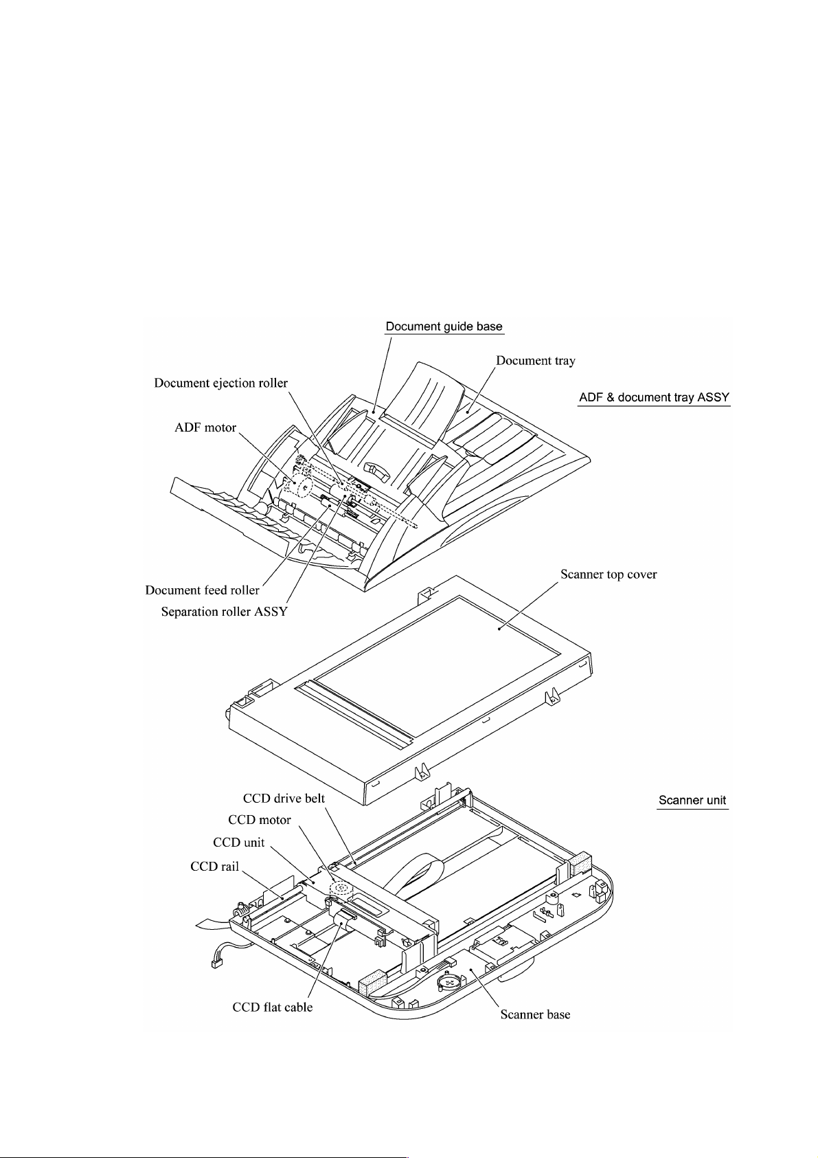
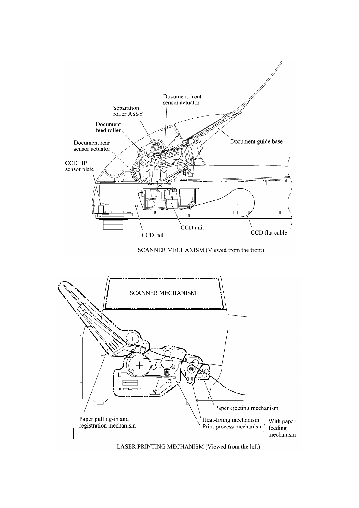
3.2.1 Scanner Mechanism
This mechanism consists of the document guide base, ADF & document tray ASSY and scanner
unit.
The ADF (automatic document feeder) unit contains a separation roller ASSY, document feed
roller ASSY, document ejection roller, ADF motor, and document front and rear sensors.
The scanner unit consists of a scanner top cover, CCD unit, CCD drive mechanism, CCD HP
sensor, and scanner base.
For details about the sensors, refer to Subsection 3.2.3.
3-4
Page 23
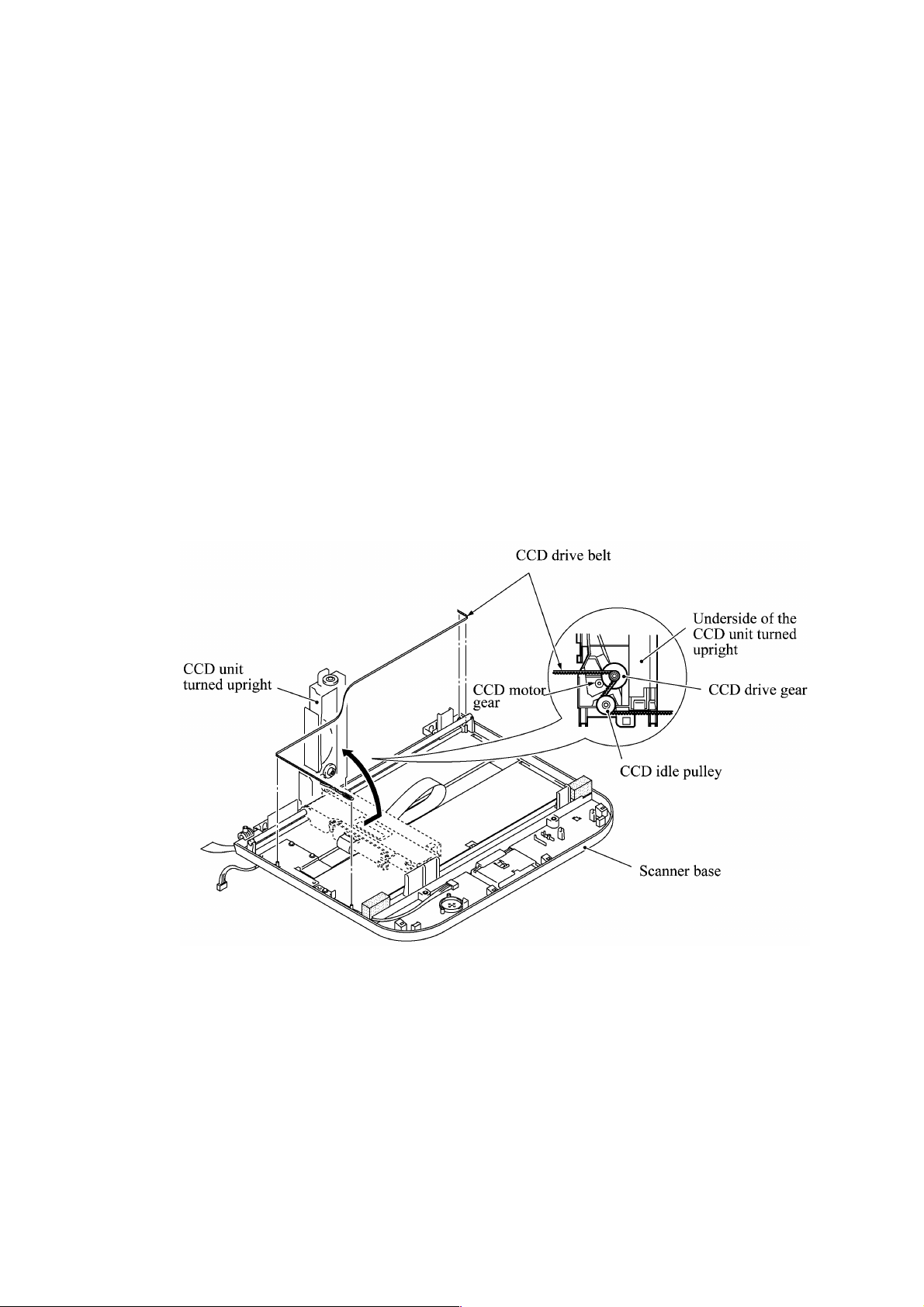
This scanner mechanism supports a dual scanning system.
(1) If you set documents on the document guide base with their faces up and start the scanning
operation, then the ADF motor rotates to pull in those documents into the ADF unit, starting
from the top sheet to the bottom, page by page. Each document curves downwards and turns to
the right with the document feed roller so as to advance above the CCD unit, and then it is fed
out to the document tray with the document ejection roller ASSY.
This way, documents move above the CCD unit being kept in a stationary position.
(2) If you open the ADF & document tray ASSY, put a sheet of document (or put a bound book
opened) on the glass of the scanner top cover, close the ADF & document tray ASSY, and
start the scanning operation, then the CCD drive mechanism will be driven.
The CCD motor built in the CCD unit rotates. As illustrated below, the CCD drive gear and
idle pulley carry the CCD drive belt on the underside of the CCD unit, so clockwise and
counterclockwise rotations of the CCD motor move the CCD unit to the right and left,
respectively.
In this scanning system, the CCD unit moves horizontally beneath a document being kept in
stationary position.
The CCD unit contains a charge coupled device (CCD) image sensor. The cold-cathode
fluorescent lamp illuminates a document and the reflected light of the scanned image data is
transmitted via the mirrors into the lens which reduces the scanned data so as to form the image on
the CCD.
3-5
Page 24
3.2.2 Laser Printing Mechanism
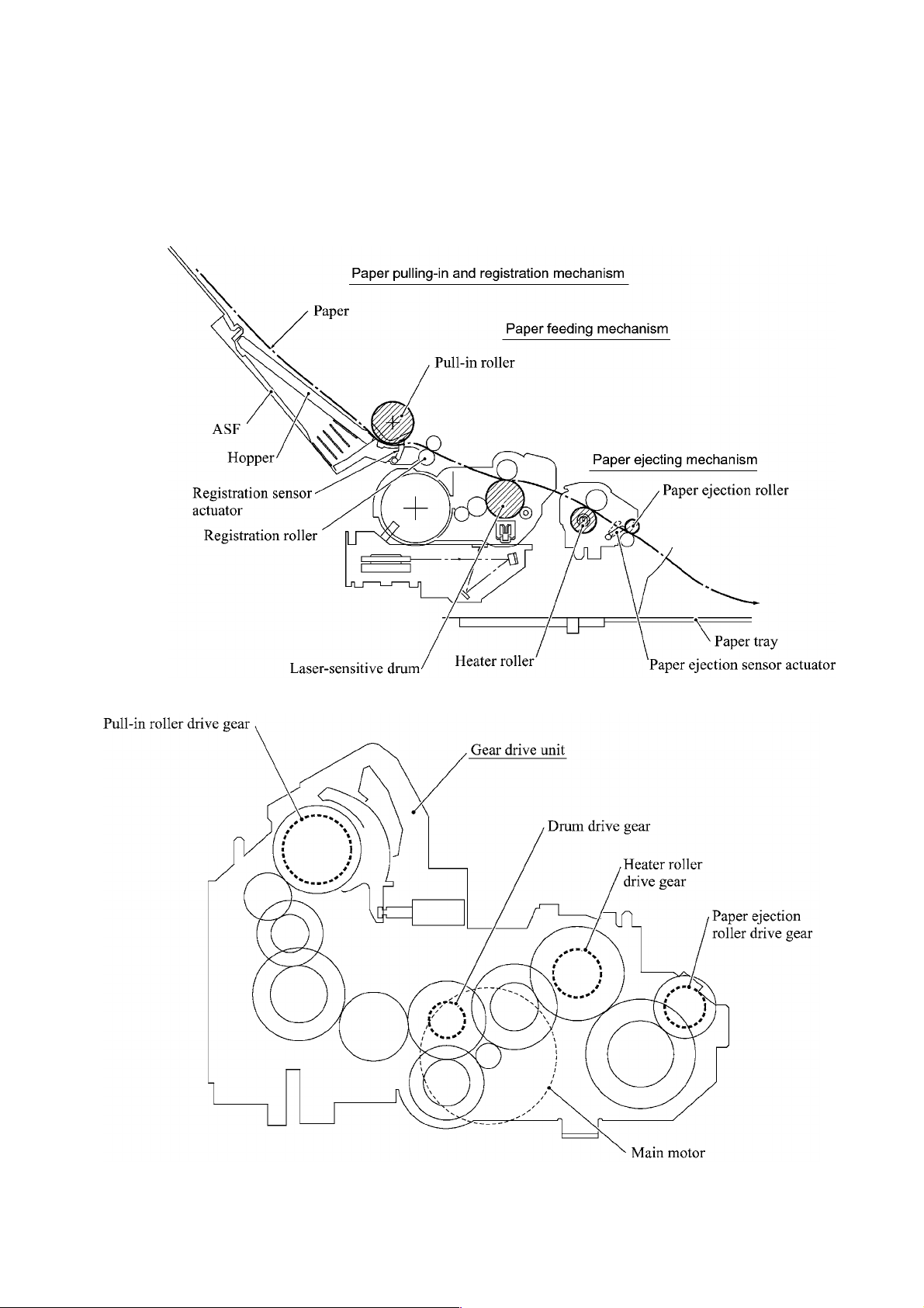
3.2.2.1 Paper pulling-in, registration, feeding, and ejecting mechanism
3-6
Page 25
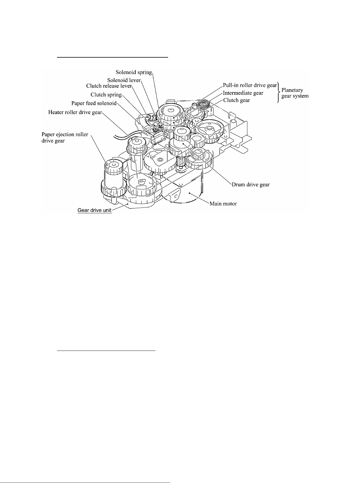
Paper pulling-in and registration mechanism
The paper pulling-in and registration mechanism consists of the pull-in roller gear (incorporated in
the auto sheet feeder ASF), planetary gear system, paper feed solenoid, solenoid lever, clutch
release lever, and registration sensor. (For the details about the sensor, refer to Subsection 3.2.3.)
If the main motor rotates clockwise, the rotation is transmitted to the intermediate gear of the
planetary gear system. As the intermediate gear rotates, the pull-in roller drive gear also rotates
since the clutch gear is locked by the solenoid lever and the clutch release lever. Accordingly, the
pull-in roller in the ASF rotates to pull in paper into the machine, a sheet at a time.
If the paper feed solenoid is retracted and the clutch release lever is operated according to the cam
profile of the pull-in roller drive gear so as to release the clutch gear, the clutch gear rotates and
the pull-in roller drive gear does not rotate. This way, the clutch gear switches the transmission of
the motor rotation to the pull-in roller drive gear on and off.
The solenoid on/off timing and the clutch release lever timing allow this mechanism to pull in a
sheet and register it against the registration roller.
Paper feeding and ejecting mechanism
If the main motor rotates clockwise, the rotation is transmitted via the gear train to the drum drive
gear, heater roller drive gear, and paper ejection roller drive gear.
After the paper passes through the heat-fixing process, it will be ejected onto the paper tray.
If the leading edge of the paper pushes up the actuator of the paper ejection sensor, the
photosensor becomes opened, signaling the start of paper ejection. If the trailing edge has passed
through the sensor actuator, the sensor becomes closed, signaling the completion of paper ejection.
Then, the main motor stops rotation.
3-7
Page 26
3.2.2.2 Print process mechanism
The print process unit works with laser beam, electrical charges, and toner. The graph below
shows the transition of electrical charge on the surface of the laser-sensitive drum through the five
processes: charging, exposing, developing, transferring, and erasing processes.
A single cycle of laser-sensitive
drum operation
Electrical
charge
on the drum
surface (V)
1
+1000
+700
+400
+300
(a)
(b)
2
3
4
1
Charges the drum surface positively.
2
Exposes the drum surface to a laser beam
to form a latent image and develops the latent
image with toner.
(a) Unexposed area (Non-image area)
(b) Exposed area (Image area)
3
Transfers the toner-formed image from the
drum to paper.
4
Erases the residual potential.
Time
3-8
Page 27
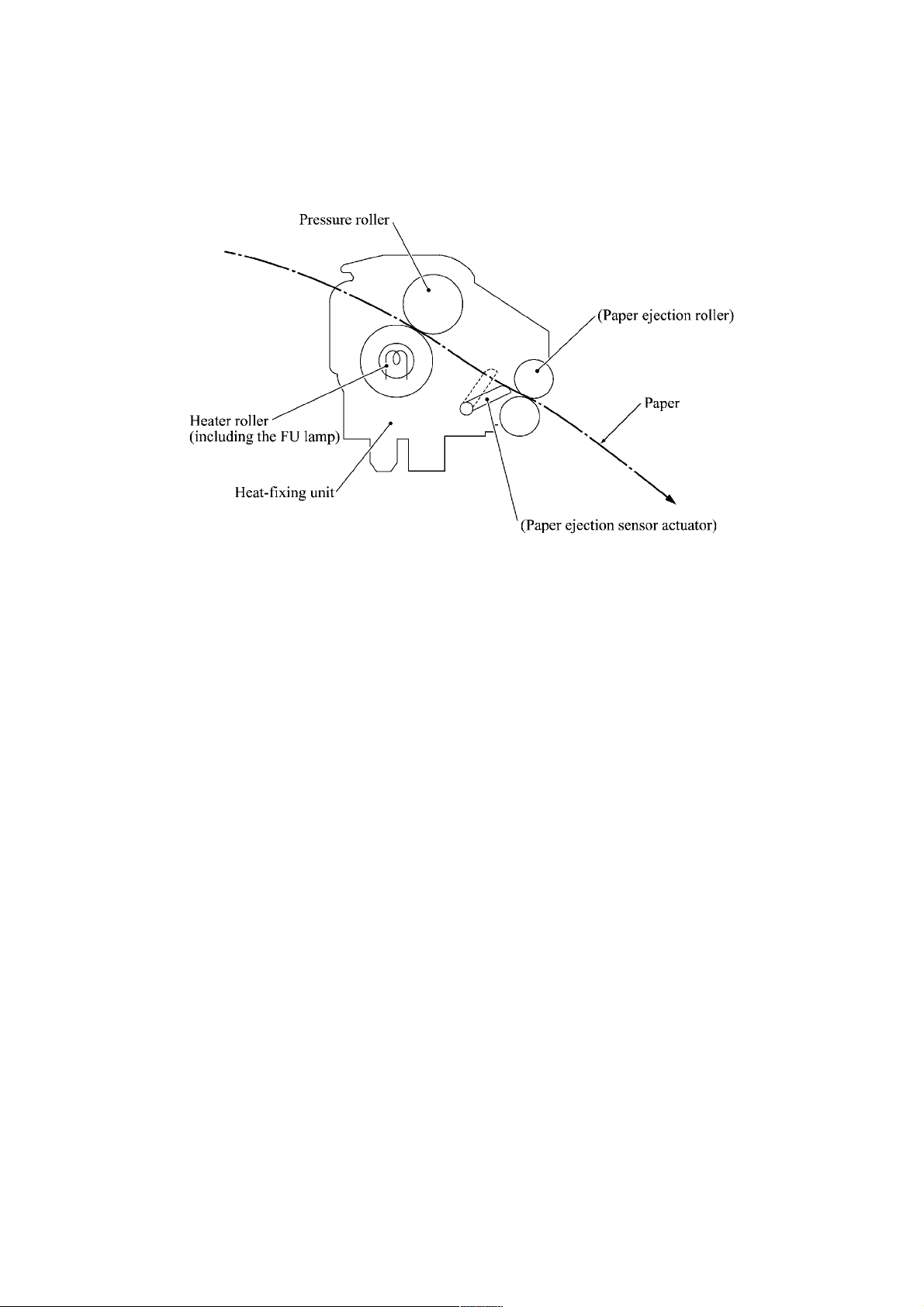
3.2.2.3 Heat-fixing mechanism
As the paper passes between the heater roller and the pressure roller in the heat-fixing unit, the
heater roller fuses the toner on the paper.
3-9
Page 28
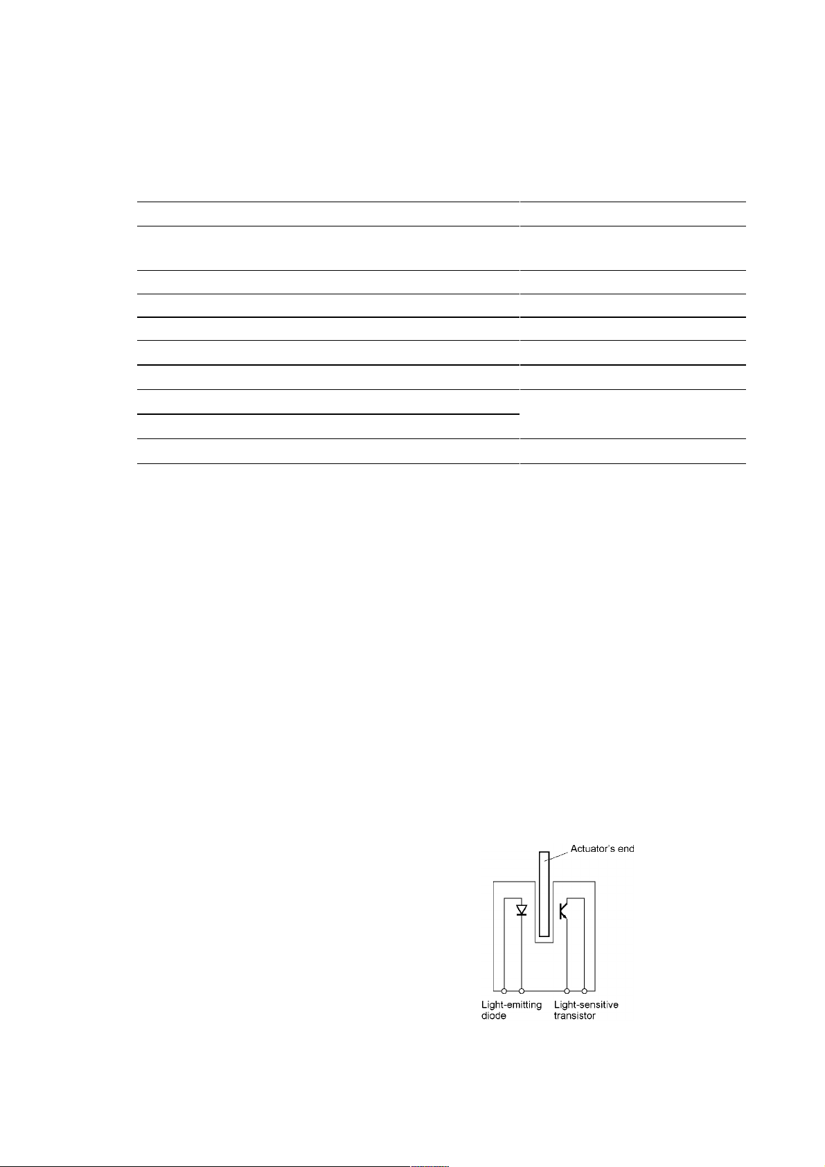
3.2.3 Sensors and Actuators
This machine has ten sensors: seven photosensors, two thermistors and a mechanical switch as
described below.
Sensor name Type Located on
Document front sensor Photosensor
Document rear sensor Photosensor
Document sensor PCB in the
ADF
Document tray open sensor Mechanical switch Document tray
Scanner open sensor Photosensor Control panel PCB
Registration sensor Photosensor Main-fan PCB
Paper ejection sensor Photosensor High-voltage power supply PCB
CCD HP sensor Photosensor CCD PCB on the CCD unit
Toner sensor Photosensor
Toner sensor PCB
Toner thermistor Thermistor
Heater thermistor Thermistor Heat-fixing unit
• Document front sensor which detects the presence of documents.
• Document rear sensor which detects the leading and trailing edges of pages to tell the control
circuitry when the leading edge of a new page has reached the starting position and when the
scan for that page is over.
• Document tray open sensor which detects whether the document tray is closed.
• Scanner open sensor which detects whether the scanner unit is closed.
• Registration sensor which detects the leading and trailing edges of paper, which allows the
controller to determine the registration timing and check paper jam.
• Paper ejection sensor which detects whether the recording paper goes out of the machine.
• CCD HP sensor which detects whether the CCD unit is placed in the home position.
• Toner sensor which detects whether there is toner or a toner cartridge is loaded.
• Toner thermistor which allows the controller to monitor the ambient temperature of the toner
cartridge.
• Heater thermistor which allows the controller to monitor the temperature of the heater roller of
the fixing unit.
These photosensors are a photointerrupter
consisting of a light-emitting diode and a
light-sensitive transistor. Each of them has
an actuator separately arranged as shown on
the next page.
3-10
Page 29
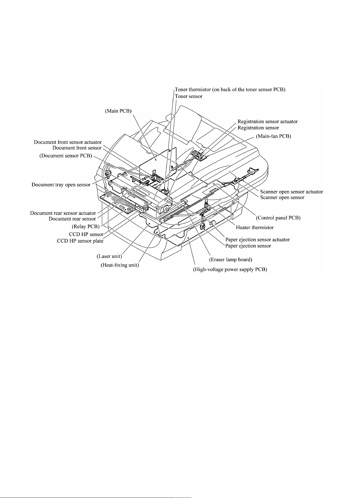
Location of Sensors and Actuators
3-11
Page 30
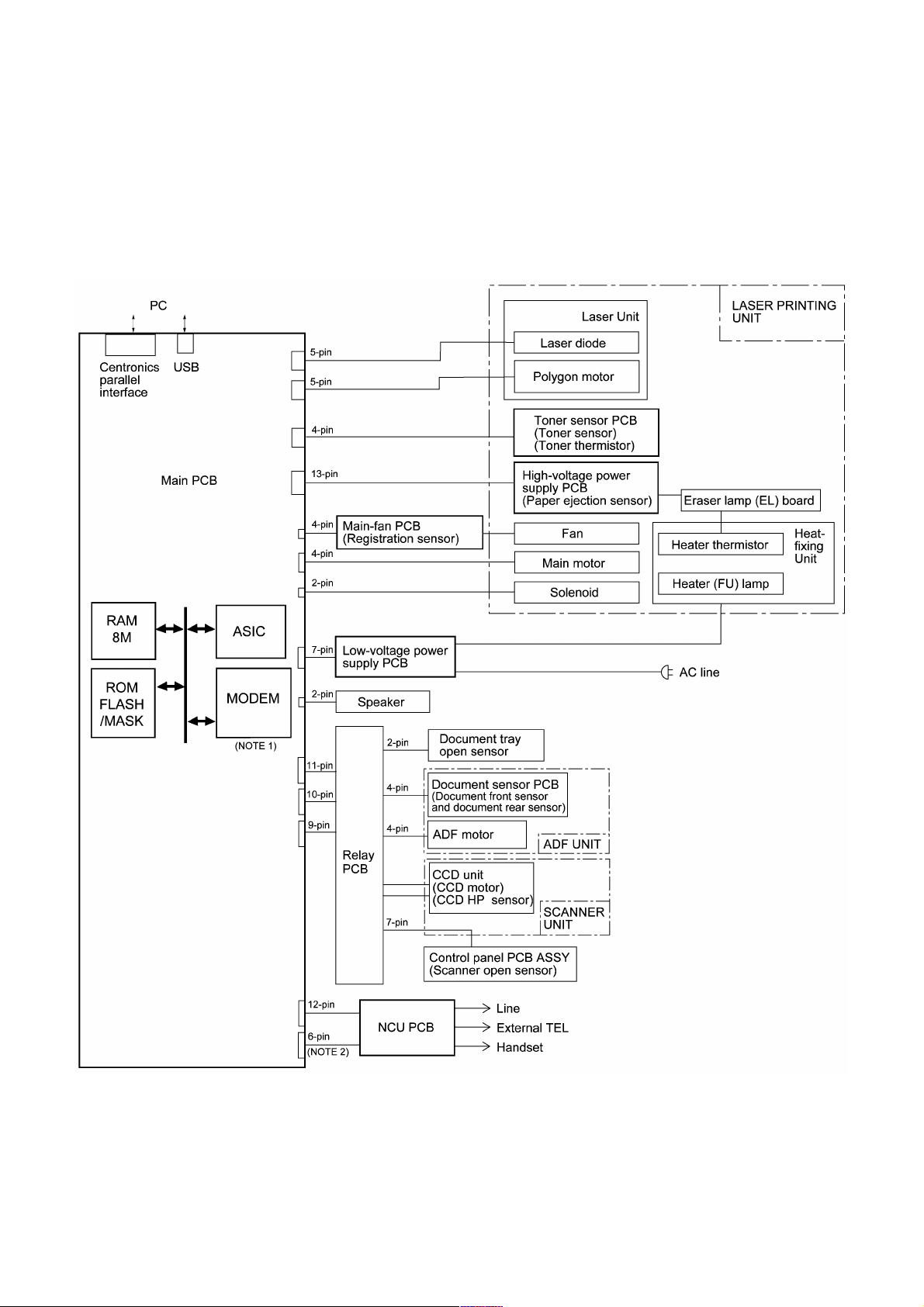
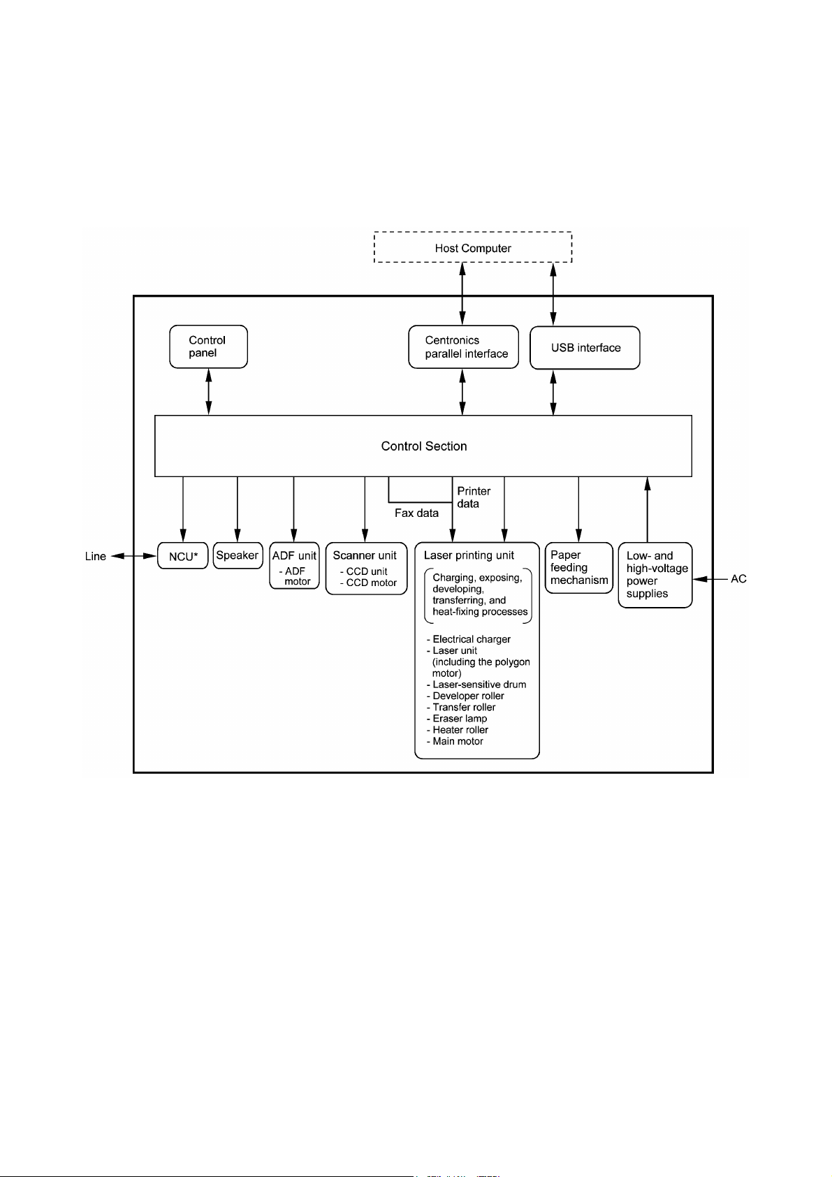
3.3 CONTROL ELECTRONICS
3.3.1 Configuration
The hardware configuration of the facsimile machine is shown below.
Configuration of Facsimile Machine
(NOTE 1) Provided on models equipped with facsimile function.
(NOTE 2) Provided on the European, Pacific, and Asian versions.
3-12
Page 31

CHAPTER
DISASSEMBLY/REASSEMBLY AND
LUBRICATION
4
Page 32

CHAPTER 4 DISASSEMBLY/REASSEMBLY AND LUBRICATION
CONTENTS
4.1 DISASSEMBLY/REASSEMBLY......................................................................................4-1
Safety Precautions........................................................................................................ 4-1
Tightening Torque List ...................................................................................................... 4-2
Preparation ...................................................................................................................4-4
How to Access the Object Component ......................................................................... 4-4
Disassembly Order Flow...............................................................................................4-5
4.1.1 ADF Cover and Document Guide Base ...............................................................4-6
4.1.2 ADF Components on the Upper ADF Chute ........................................................4-7
4.1.3 ADF Components on the Lower ADF Chute ......................................................4-12
4.1.4 Document Tray Open Sensor and Document Stopper ......................................4-17
4.1.5 Scanner Unit and Control Panel ASSY (Together with Document Tray) ...........4-18
4.1.6 Disassembly of the Control Panel ASSY............................................................ 4-25
4.1.7 Disassembly of the Scanner Unit ....................................................................... 4-26
4.1.8 Front Cover ........................................................................................................4-31
4.1.9 Relay PCB..........................................................................................................4-32
4.1.10 Scanner Mount ................................................................................................... 4-33
4.1.11 Board Access Cover and Auto Sheet Feeder (ASF) .......................................... 4-34
4.1.12 Heat-fixing Unit, FU Lamp, and Paper Ejection Sensor Actuator....................... 4-40
4.1.13 Laser Unit and Toner Sensor PCB.....................................................................4-42
4.1.14 Main PCB ...........................................................................................................4-43
4.1.15 Bottom Plate.......................................................................................................4-46
4.1.16 Low-voltage Power Supply PCB......................................................................... 4-47
4.1.17 High-voltage Power Supply PCB........................................................................ 4-48
4.1.18 Main-Fan PCB, Duct, and Fan ...........................................................................4-49
4.1.19 Power Supply Shield ..........................................................................................4-50
4.1.20 Speaker .............................................................................................................. 4-51
4.1.21 Gear Drive Unit...................................................................................................4-52
Page 33

4.1.22 PCB Support and NCU PCB ..............................................................................4-54
4.1.23 Scanner Grounding Plate ...................................................................................4-55
4.1.24 EL (Eraser Lamp) Board ....................................................................................4-56
4.1.25 Harness Routing.................................................................................................4-57
4.1.26 Cleaning of High-voltage Contacts and Grounding Contacts............................. 4-61
4.2 LUBRICATION............................................................................................................... 4-62
4.3 PERIODICAL REPLACEMENT PARTS........................................................................ 4-64
4.4 MTBF/MTTR ..................................................................................................................4-65
Page 34

4.1 DISASSEMBLY/REASSEMBLY
n Safety Precautions
To prevent the creation of secondary problems by mishandling, observe the following precautions
during maintenance work.
(1) Unplug the power cord from the power outlet before replacing parts or units. When having
access to the power supply, be sure to unplug the power cord from the power outlet.
(2) When servicing the optical system of the laser printing unit, be careful not to place
screwdrivers or other reflective objects in the path of the laser beam. Be sure to take off any
personal accessories such as wrist watches and rings before working on the printer. A
reflected beam, though invisible, can permanently damage your eyes.
(3) If the machine has been printing, allow the heat-fixing unit sufficient time to cool down before
starting maintenance jobs. It is HOT!
(4) Be careful not to lose screws, washers, or other parts removed for parts replacement.
(5) Do not remove gears from the document feed roller ASSY or ejection roller ASSY if at all
possible. Once removed, they will become unusable and new gears will have to be put back in.
(6) When using soldering irons and other heat-generating tools, take care not to damage the resin
parts such as wires, PCBs, and covers.
(7) Before handling the PCBs, touch a metal portion of the machine to discharge static electricity;
otherwise, the electronic parts may be damaged due to the electricity charged in your body.
(8) When transporting PCBs, be sure to wrap them in conductive sheets such as aluminum foil.
(9) Be sure to reinsert self-tapping screws correctly, if removed.
(10) Tighten screws to the torque values listed on the next page.
(11) When connecting or disconnecting cable connectors, hold the connector bodies not the cables.
If the connector has a lock, always slide the connector lock to unlock it.
(12) Before reassembly, apply the specified lubricant to the specified points. (Refer to Subsection
4.2 in this chapter.)
(13) After repairs, check not only the repaired portion but also that the connectors and other related
portions function properly before operation checks.
4-1
Page 35

Tightening Torque List
Location Screw type Q’ty Tightening torque
N•m (kgf•cm)
ADF thickness adjuster Taptite, pan B M3x6 1 0.39 ±0.10 (4 ±1)
Upper ADF chute Taptite, cup B M3x10 2 0.69 ±0.10 (7 ±1)
Lower ADF chute Taptite, cup B M3x10 2 0.69 ±0.10 (7 ±1)
Grounding wire Taptite, cup B M3x10 1 0.69 ±0.10 (7 ±1)
ADF drive unit Taptite, cup B M3x8 2 0.69 ±0.10 (7 ±1)
ADF motor Screw, pan (s/p washer) M3x6 1 0.69 ±0.10 (7 ±1)
Grounding wire on the scanner mount Taptite, cup B M3x10 1 0. 3 9 ±0.10 (4 ±1)
Document tray Taptite, bind B M4x12 2 0. 9 8 ±0.20 (10 ±2)
Hinge base R Taptite, cup B M3 x10 3 0.69 ±0.10 (7 ±1)
Hinge L Taptite, cup B M3x10 3 0.69 ±0.10 (7 ±1)
Control panel ASSY Taptite, cup B M3x12 6 0.39 ±0.10 (4 ±1)
Scanner open sensor PCB Taptite, cup B M3x8 1 0.39 ±0.10 (4 ±1)
Reinforcement plate Taptite, cup B M3x6 7 0.39 ±0.10 (4 ±1)
Control panel PCB Taptite, cup B M3x6 2 0.39 ±0.10 (4 ±1)
Scanner top cover T aptite, cup B M4x12 4 0.98 ±0.20 (10 ±2)
Guide plate Taptite, cup B M3x8 3 0.69 ±0.10 (7 ±1)
CCD HP sensor plate Taptite, cup B M3x8 1 0.69 ±0.10 (7 ±1)
Flat cable clamp Taptite, cup B M3x8 2 0.69 ±0.10 (7 ±1)
Front cover guides Taptite, cup B M3x10 2 0.69 ±0.10 (7 ±1)
Relay PCB Taptite, cup B M3x10 2 0.39 ±0.10 (4 ±1)
Scanner mount Taptite, bind B M4x12 2 0.98 ±0.20 (10 ±2)
Board access cover Taptite, bind B M4x12 2 0.78 ±0.10 (8 ±1)
Release lever Taptite, bind B M4x10 1 0.98 ±0.20 (10 ±2)
Grounding leaf spring R Taptite, bind B M2.6x8 1 0 .39 ±0.10 (4 ±1)
Grounding leaf spring L Taptite, bind B M2.6x8 2 0.39 ±0.10 (4 ±1)
Heat-fixing unit Taptite, cup B M4x16 2 0.98 ±0.20 (10 ±2)
Fixing unit upper cover Taptite, bind B M3x12 2 0.69 ±0.20 (7 ±2)
Lock plate Taptite, pan B M3x10 1 0.69 ±0.20 (7 ±2)
Fuse plate R Screw, pan (washer) M2.6x6DA 1 0.39 ±0.10 (4 ±1)
Laser unit Taptite, bind B M4x12 3 0.98 ±0.20 (10 ±2)
Main shield Taptite, cup S M3x6 2 0.69 ±0.20 (7 ±2)
Parallel interface connector T aptite, pan S M3x12 2 0. 69 ±0.20 (7 ±2)
Main PCB Taptite, cup S M3x6 2 0. 69 ±0.20 (7 ±2)
Bottom plate Taptite, bind B M4x12 5 0.9 8 ±0.20 (10 ±2)
Taptite, cup S M3x6 4 0. 69 ±0.20 (7 ±2)
4-2
Page 36

Low-voltage power supply PCB Taptite, cup S M3x6 2 0. 69 ±0.20 (7 ±2)
(Low-voltage insulator sheet)
Grounding wire Screw, pan (washer) M4x8DB 1 0.39 ±0.20 (4 ±2)
Power inlet support Taptite, cup S M3x6 1 0. 69 ±0.20 (7 ±2)
High-voltage power supply PCB Taptite, bind B M4x12 1 0.98 ±0.20 (10 ±2)
Duct Taptite, bind B M4x12 2 0.98 ±0.20 (10 ±2)
Fan support Taptite, cup B M3x8 1 0. 49 ±0.20 (5 ±2)
Power supply shield Taptite, cup S M3x6 2 0. 69 ±0.20 ( 7 ±2)
Gear drive unit Taptite, bind B M4x14 4 0. 98 ±0.20 (10 ±2)
Main motor Taptite, cup S M3x6 2 0. 69 ±0.20 (7 ±2)
Gear support plate Taptite, cup S M3x16 2 0. 69 ±0.20 (7 ±2)
PCB support Taptite, bind B M4x12 2 0. 98 ±0.20 (10 ±2)
NCU shield Taptite, cup S M3x6 2 0. 69 ±0.20 (7 ±2)
NCU PCB Taptite, cup S M3x6 1 0. 69 ±0.20 (7 ±2)
Scanner grounding plate Taptite, cup B M3x8 1 0. 49 ±0.20 (5 ±2)
4-3
Page 37

n Preparation
Prior to proceeding to the disassembly procedure,
(1) Unplug
- the modular jack of the telephone line (only for models equipped with the fax function),
- the power cord,
- the modular jack of the curled cord (and remove the handset),
- the PC interface cable (parallel cable or USB cable) if connected (Not shown below), and
- the modular jack of an external telephone set if connected (Not shown below).
(2) Remove
- the paper support,
- the paper tray, and
- the drum unit (with the toner cartridge loaded)
n How to Access the Object Component
• On the next page is a disassembly order flow which helps you access the object components. To
remove the gear drive unit, for example, first find it on the flow and learn its number (
this case). You need to remove parts numbered
access the gear drive unit.
• Unless otherwise specified, the disassembled parts or components should be reassembled in the
reverse order of removal.
in
, , , , , , and so as to
4-4
Page 38

n Disassembly Order Flow
4-5
Page 39

4.1.1 ADF Cover and Document Guide Base
(1) Open the ADF cover, press its front end to release the boss, and take it off (in the direction of
arrows
, , and ).
(2) Release the two latches of the document guide base and slide it up straight along the guides.
NOTE: Do not turn it to the left. Doing so will break the groove sections of the document
guide base.
n Reassembling Notes
• When setting the ADF cover back into place, fit its bottom edge under the stopper tabs as
illustrated above.
4-6
Page 40

4.1.2 ADF Components on the Upper ADF Chute
Gear cover
(1) As illustrated below, insert the tip of a flat screwdriver into the slot and lift up the right edge
of the gear cover (arrow
) and move the gear cover to the front (arrow ).
4-7
Page 41

Separation roller ASSY and document feed roller
(2) From the rear end of each of the separation roller ASSY and document feed roller, remove the
plastic retaining ring. Lift up the rear ends of them and take them out together with bushings
S.
NOTE: Take care not to drop bushings S.
4-8
Page 42

Reassembling Note: If you have disassembled the separation roller ASSY, set the separation
roller on its shaft with the boss facing towards the pin and then snap the plastic retaining ring
into place, as illustrated below.
Reassembling Note: When setting the separation roller ASSY, take care not to apply force to
the spring plate at an angle, as illustrated on the previous page.
Reassembling Note: After setting the rear end of the separation roller ASSY or document
feed roller to the ADF drive unit, fit its bushing into the cutout provided in the ADF drive unit
and then set the plastic retaining ring inside the upper ADF chute, as illustrated on the
previous page.
Separation rubber unit, ADF thickness adjuster, and pressure rollers
(3) Turn the separation rubber unit as shown below and lift it up.
4-9
Page 43

(4) Remove the screw and take the ADF thickness adjuster out of the upper ADF chute.
NOTE: The ADF thickness adjuster is lubricated with grease, so take care not to smear
surrounding parts with the grease when handing the ADF thickness adjuster.
(5) At either end of the pressure roller shaft, press the latch to the right and take out the pressure
rollers and their shaft. Then remove their springs.
4-10
Page 44

Upper ADF chute
(6) Remove the two screws from the upper ADF chute.
(7) Open the document tray (
).
(8) From the underside of the document tray, release the two leftmost latches (
up the left end of the upper ADF chute (
).
) and then pull
Reassembling Note: When latching the upper ADF chute, first fit tabs (1) of the right end
into the openings provided in the document tray, then press latches (2), (3), and (4) into place
in this order as shown above.
4-11
Page 45

4.1.3 ADF Components on the Lower ADF Chute
Document front and rear sensor actuators
(1) Lift up the document front sensor actuator. Fully turn the document rear sensor actuator
counterclockwise, then lift it up.
Document sensor PCB
(2) Take the document sensor harness out of the cable hooks, then disconnect it from the
document sensor PCB.
(3) Press the locking pawl to the front and take out the document sensor PCB.
4-12
Page 46

Document guide clips
(4) Press the tab of each document guide clip. Each clip will snap out of the document ejection
roller shaft.
Document ejection roller
(5) Remove the pawled bushing from the front end of the document ejection roller shaft by
pulling its pawls outwards.
(6) Slide the rear bushing to the rear and then lift up the document ejection roller.
4-13
Page 47

Reassembling Note: When fitting the rear bushing of the document ejection roller into the
cutout of the ADF drive unit, orient the boss as illustrated on the previous page.
Document pressure bar
(7) Open the ADF & document tray ASSY.
(8) Pull either of the front and rear supports of the document pressure bar outwards and remove
the document pressure bar. The spring also comes off.
Reassembling Note: After setting the document pressure bar, check in the direction of arrow
"X" that the spring is into place as illustrated above.
4-14
Page 48

Lower ADF chute, pinch rollers, and ADF motor
(9) Take the document sensor harness out of cable hooks provided on the lower ADF chute.
(10) Disconnect the ADF motor harness from the motor, then take its harness out of the cable
guides and hooks.
(11) Release the grounding wire from the ADF drive unit by removing the screw.
(12) Remove the two screws from the lower ADF chute.
(13) Lift up the lower ADF chute in the direction of the arrow shown below, taking care not to
touch the anti-static brush.
(14) Press the latch to the left and remove the pinch rollers and its shaft.
When reinstalling the lower ADF chute,
turn the planet gear counterclockwise
(when viewed from the rear)
ADF drive unit
Taptite, cup B M3x10
ADF motor harness
Taptite, cup B M3x10
Grounding wire
Document sensor harness
Planet gear
Grounding wire
Lower ADF chute
Anti-static brush (Do not touch this.)
Pinch roller shaft
Pinch rollers
Pinch roller spring
Latch
4-15
Page 49

(15) Remove the two screws from the ADF drive unit and release the ADF motor.
NOTE: When using a screwdriver, take care not to scratch or damage gears on the ADF drive
unit.
Reassembling Note: When setting the ADF motor, hook the non-screw side of the flange on
section "x" (shown above) and secure it with the screw.
Reassembling Note: Before reinstalling the lower ADF chute to the document tray, be sure to
turn the planet gear on the ADF drive unit counterclockwise when viewed from the rear, as
illustrated on the previous page.
Reassembling Note: For routing the ADF motor harness, document sensor harness, and
grounding wire, refer to Subsection 4.1.25, "Harness routing A." Secure the grounding wire at
the angle shown on the previous page and let it hold down the ADF motor harness and
document sensor harness as shown in "Harness routing A."
4-16
Page 50

4.1.4 Document Tray Open Sensor and Document Stopper
(1) Disconnect the document tray open sensor harness from the sensor.
(2) Open the document tray.
(3) Press the right and left latches of the document tray open sensor with the tip of a flat
screwdriver as shown below and push it down.
(4) Slightly open the document stopper and remove it while warping it.
4-17
Page 51

4.1.5 Scanner Unit and Control Panel ASSY (Together with Document Tray)
(1) Pull the scanner open lever and open the scanner unit.
(2) Unhook the two scanner springs. (The right-hand scanner spring is shorter than the left-hand
one.)
4-18
Page 52

(3) At each of the right and left rear edges of the front cover, push up the lock of the front cover
connector (in the direction of arrow
(arrow
) to release its boss from the front cover connector.
) and press the rear edge of the front cover inwards
(4) While keeping the scanner unit open, unlatch the relay PCB cover and take it out.
4-19
Page 53

(5) While keeping the scanner unit open (in the direction of arrow ), disconnect the CCD flat
cable (arrow
) from the relay PCB.
NOTE: Handle the CCD flat cable with care.
(6) Open the scanner unit further and lift up its rear edge to disengage it from the scanner mount.
Then shift the scanner unit to the front right as shown below (arrow
) so that the relay PCB
can be fully seen.
CAUTION: When putting the scanner unit on the scanner mount, take special care not to
bend, wrinkle, or scratch the CCD flat cable or not to break the boss of the front cover (that is
provided for the scanner open sensor actuator) by the bottom of the scanner unit.
4-20
Page 54

(7) Disconnect the following harnesses from the relay PCB:
- Document tray open sensor harness
- Document sensor harness
- ADF motor harness
- Panel harness
(8) Release the grounding wire (coming from the ADF drive unit) by removing the screw.
(9) Lift up the scanner unit together with the document tray and control panel ASSY.
4-21
Page 55

(10) Remove the two screws from the bottom rear of the hinges.
(11) Be sure to open the document tray, then release the harnesses (bound and covered with the
cable sheath) from the latch and move them to the front in the opening.
(12) Lift up the document tray.
(13) From the hinge base R, remove the hinge arm as shown below. Remove the three screws and
release the hinge base R.
(14) From the hinge L that should be kept opened, remove the three screws.
4-22
Page 56

(15) Remove the six screws from the underside of the scanner base.
(16) Release the two latches of the control panel ASSY from the scanner base.
(17) Slightly lift up the control panel ASSY and disconnect the panel harness from the control
panel PCB.
(18) Turn the scanner open sensor actuator as shown below and remove it.
(19) Remove the screw from the scanner open sensor PCB. Then the control panel ASSY is
separated from the scanner unit.
(For the disassembly procedure of the control panel ASSY and scanner unit, refer to
Subsections 4.1.6 and 4.1.7, respectively.)
(20) Remove the lever spring.
(21) Insert the tip of a flat screwdriver into slit "s," push up the lock, and remove the scanner open
lever in the direction of the arrow.
4-23
Page 57

n Reassembling Notes
• When setting the document tray on the scanner unit, pass the bound harnesses (ADF motor
harness, document sensor harness, document tray open sensor harness, and grounding wire)
through the front section of the opening provided in the left rear corner of the document tray,
with its bound section facing up (see the illustration given on page 4-22).
Move those bound harnesses to the rear section of the opening. Route the bound section through
the cable guide so that the cable binder comes into contact with the cable guide as illustrated on
page 4-22. Refer to Subsection 4.1.25 "Harness routing A."
• When putting the scanner unit on the scanner mount, take special care not to bend, wrinkle, or
scratch the CCD flat cable or not to break the boss of the front cover by the bottom of the
scanner unit. (See the illustration given on page 4-20.)
• Route the document sensor harness, document tray open sensor harness, ADF motor harness,
panel harness, and grounding wire on the scanner mount as shown on page 4-21. Wind the
document sensor harness and document tray open sensor harness around the cable clip on the
relay PCB, and then bend the cable clip as shown in Subsection 4.1.25, "Harness routing B."
4-24
Page 58

4.1.6 Disassembly of the Control Panel ASSY
(1) Remove the two screws from the control panel PCB.
(2) Slightly lift up the control panel PCB, then unlock the FPC key connector and disconnect the
FPC key. Next, unlock the LCD cable connector and disconnect the LCD flat cable.
(3) Remove the seven screws and take off the reinforcement plate and FPC key.
(4) As shown below, pull the lock arms outwards to release the LCD and pull the LCD flat cable
gently.
n Reassembling Notes
• Before reinstalling the LCD to the control panel, wipe fingerprints or dust off the LCD surface
and control panel window with a soft cloth.
• A new LCD is covered with a protection sheet. Before installing it, remove the protection sheet.
4-25
Page 59

4.1.7 Disassembly of the Scanner Unit
The disassembly job of the scanner unit should be done in a clean room to prevent dust or dirt
from getting into the scanner unit.
(1) Remove the four screws from the scanner top cover.
(2) Separate the scanner top cover from the scanner base.
4-26
Page 60

(3) Release the CCD drive belt from boss "a."
(4) At the left front end of the CCD drive belt, unhook the belt spring from boss "b."
NOTE: Do not remove the belt spring or belt clip from the CCD drive belt.
(5) As illustrated below, move the CCD unit to the right, lift up its front end and turn the CCD
unit upright. The CCD drive belt will slip off the CCD idle pulley and gear on the underside of
the CCD unit.
4-27
Page 61

(6) Disconnect the CCD flat cable from the CCD PCB, then release the cable that is attached to
the underside of the CCD unit with double-sided adhesive tape.
NOTE: Only when the CCD unit or CCD flat cable is defective and requires replacement,
release the flat cable. Once released, the flat cable should be attached using new double-sided
adhesive tape.
(7) Lift up the CCD rail together with the CCD unit from the scanner base, then pull out the CCD
rail.
NOTE: When handling the CCD unit, do not touch the CCD PCB or glasses but hold the
hatched sections as shown on the next page.
4-28
Page 62

(8) Remove the three screws and lift up the guide plate.
(9) Remove the screw from the CCD HP sensor plate.
4-29
Page 63

(10) Remove the two screws and take off the flat cable clamp.
(11) To take out the panel harness, remove sponges F and R that are backed with adhesive tape.
NOTE: Once removed, those sponges will become unusable and new parts will have to be put
back in.
(12) To take out the CCD flat cable, remove sponge R.
n Reassembling Notes
• When replacing the CCD unit with a new one, you need to attach a CCD protector to it as
specified on page 4-28. A new CCD protector is covered with a protection sheet, so remove the
protection sheet before attaching.
• When using a new CCD flat cable, fold it and secure it to the scanner base with double-sided
adhesive tape and sponge R (backed with adhesive tape) as illustrated above.
Then attach it to the underside of the CCD unit with double-sided adhesive tape.
• When reassembling the components inside the scanner unit, use screws (Taptite, cup B M3x8).
Never use longer ones (e.g., M3x10). Using longer ones will bore a hole in the scanner base.
• When installing the CCD drive belt to the scanner base, set its rear end within the range
specified on page 4-27.
4-30
Page 64

4.1.8 Front Cover
(1) Press the rear ends of the front cover inwards (in the direction of arrow ) to release bosses
"a" from the front cover guides.
(2) Remove the screw from each of the front cover guides.
(3) While pulling the tab of each front cover guide up and to the front (in the direction of arrow
) to release the guide from boss "b," remove the guide in the direction of arrow .
n Reassembling Notes
• When setting the front cover guides back into place, fit sections "y" and "x" into "Y" and "X" of
the scanner mount, respectively, while pushing the guides down and to the front.
4-31
Page 65

4.1.9 Relay PCB
(1) Disconnect the three relay harnesses from the relay PCB.
(2) Remove the two screws. The cable clip will come off and the grounding wire will be released.
(3) Lift up the relay PCB.
Taptite, cup B M3x10
4-32
Page 66

4.1.10 Scanner Mount
(1) Remove the harness cover.
NOTE: Once removed, the harness cover will become unusable and a new part will have to
be put back in.
(2) Remove the relay (ADF) harness from seven latches and then bring it to the right.
(3) Remove the two screws from the scanner mount
(4) Remove the scanner mount in the direction of the arrows.
n Reassembling Notes
• Route the relay (ADF) harness through seven latches on the scanner mount. Refer to Subsection
4.1.25, "Harness routing C."
4-33
Page 67

4.1.11 Board Access Cover and Auto Sheet Feeder (ASF)
(1) Remove the two screws from the board access cover. (Those screws secure also the ASF to
the main cover.)
(2) Push down the top of the board access cover to release the two latches from the main cover,
then pull it to the rear.
(3) Pull the ASF to the front and then lift it up.
4-34
Page 68

[Disassembling the ASF]
1) Unhook the release lever spring.
2) Remove screw "a" and pull out the release lever.
3) Turn the release cam to the front and pull it out to the left.
4-35
Page 69

4) At the right end of the ASF, remove the screw from the grounding leaf spring R. (It is not
necessary to remove the leaf spring.) Next pull out the pawled bushing R.
At the left end of the ASF, remove the sector gear and its spring. Unlatch the pawled bushing
L to the left and then remove it from the paper pull-in roller shaft. Remove the paper pull-in
roller.
5) Push the right and left ends of the separation pad ASSY inwards and take it out. The spring
also comes off.
4-36
Page 70

6) Turn the ASF upside down, then remove the registration sensor actuator.
4-37
Page 71

7) There are two sets of pinch roller units. At each set, remove the leaf spring (in the order of
to shown below), pinch rollers, and pinch roller shaft.
8) At the right end of the paper feed roller, remove the screw and take off the grounding leaf
spring R if you have not removed it in step 4) above.
Remove the pawled pushing R.
9) At the left end of the paper feed roller, remove two screws and take off the grounding leaf
spring L, pawled PF gear, and idle gear.
Then remove the paper feed roller.
4-38
Page 72

10) Press the lock arm provided at the left inside of the ASF to the rear with a screwdriver, slide
the ASF chute ASSY to the left, and take it out to the front.
NOTE: To replace only the black film attached to the chute, do not remove the chute ASSY
from the ASF.
NOTE: A new chute and black film will be provided separately. When replacing the ASF
chute ASSY, first set the chute into the ASF and then attach the black film to the chute. If you
first attach the black film to the chute and then set the ASF chute ASSY, then the black film
may be bent or wrinkled.
n Reassembling Notes
• Set the paper feed roller into the ASF with the D-shaped end facing leftwards.
• Set the paper pull-in roller into the ASF with the D-shaped end facing leftwards.
• When setting the release lever back into place, turn the release cam to the rear and then set the
release lever so that the bottom end of the release lever comes in the front of the boss provided
on the ASF, as illustrated on page 4-35.
4-39
Page 73

4.1.12 Heat-fixing Unit, FU Lamp, and Paper Ejection Sensor Actuator
(1) Remove the two screws from the heat-fixing unit.
(2) Lift up the heat-fixing unit and disconnect the blue and brown heater wires (of the heater
harness) from the heat-fixing unit. Then disconnect the heater thermistor harness from the EL
(eraser lamp) board.
(3) Remove the paper ejection sensor actuator from the bottom of the heat-fixing unit.
4-40
Page 74

(4) To take out the FU lamp from the heat-fixing unit, remove two screws "a."
(5) Fully open the upper cover and remove it.
(6) Unlatch the idle gear 16 and remove it.
(7) Loosen screw "b."
(8) Remove screw "c" and take out the lock plate.
(9) Slightly lift up the left end of the heater roller and hold the left end of the FU lamp. While
pinching the fuse plate R with your right hand, pull out the FU lamp from the heater roller.
CAUTION: Do not touch the FU lamp. If you have touched it, clean it thoroughly with
alcohol.
n Reassembling Notes
• When setting the FU lamp into the heat-fixing unit, be sure to insert the right edge of the wire
into the folded fuse plate R.
• A new heat-fixing unit will be provided with the heater thermistor harness being taped to the
unit. When installing the unit, remove the tape.
• Route the blue and brown heater wires on the main cover as illustrated in Subsection 4.1.25,
"Harness routing F."
4-41
Page 75

4.1.13 Laser Unit and Toner Sensor PCB
(1) Disconnect the polygon motor flat cable, toner sensor harness, and laser diode harness from
the main PCB.
(2) Remove the three screws from the laser unit.
(3) Lift up the laser unit.
NOTE: When handling the laser unit, take care not to touch the inside of the unit, glass, or
mirror.
NOTE: On the small PCB at the right side of the laser unit is a 2-pin connector which is for
the adjustment in the factory. Do not disturb it.
n Reassembling Notes
• When replacing the laser unit with a new one, be sure to attach a ferrite core to the laser diode
harness of the new laser unit. Wind the harness around the ferrite core by two turns as shown
above, just like the laser diode harness of the old laser unit.
• On the underside of the laser unit, route the laser diode harness, polygon motor flat cable, and
toner sensor harness as illustrated in Subsection 4.1.25, "Harness routing G."
• Before putting the laser unit back into place, check for any toner particles, paper dust or dirt,
and clean them out.
• Make sure that the sponge is placed below the laser unit.
4-42
Page 76

4.1.14 Main PCB
(1) Disconnect the following harnesses and flat cable from the main PCB:
• NCU harness
• Low-voltage power harness
• Main motor harness
• Relay (ADF) harness
• Relay (CCD/PANEL) harness
• High-voltage power flat cable
• Main-fan harness
• Solenoid harness
• Relay (CCD/SEN) harness
• Speaker harness
(2) Remove two screws "a" from the main shield.
(3) Remove two screws "b" from the parallel interface connector.
(4) Remove two screws "c" from the main PCB and then take it off from the PCB support. The
grounding wire will be released.
4-43
"a" and "c": Taptite, cup S M3x6
"b": Taptite, pan S M3x12
Page 77

n Reassembling Notes
• Be sure to route the harnesses and flat cable as illustrated in Subsection 4.1.25, "Harness routing
D."
Make sure that the main motor harness is routed closest to the main PCB and that the relay
(CCD/SEN) harness is routed after other harnesses are connected.
Make sure that harnesses having ferrite cores are taped. In particular, the main motor harness
should be taped above and below the ferrite core.
• If you replace the main PCB, be sure to follow the flowchart given on the next page.
4-44
Page 78

Setting up the main PCB after replacement
4-45
Page 79

4.1.15 Bottom Plate
(1) Turn the machine upside down.
(2) Remove the nine screws (four "x" and five "y") from the bottom plate, then lift it up.
"x": Taptite, cup S M3x6
"y": Taptite, bind B M4x12
4-46
Page 80

4.1.16 Low-voltage Power Supply PCB
(1) Remove screw "a" and take off the low-voltage insulator sheet.
(2) Remove screws "c" and "d" to release the grounding wire and power inlet support,
respectively.
(3) While pulling the right rear of the main cover (placed upside down) outwards to release the
ON/OFF switch, lift up the power inlet support.
For the new type of the power inlet support having an opening: You need to cut off the binder
that fastens the blue and brown lead wires of the AC power cord to the power inlet support.
(4) Remove screw "b."
(5) Slightly lift up the low-voltage power supply PCB and disconnect the low-voltage power
harness and heater harness (of the blue and brown wires).
Power inlet support
(Opening provided in the
new type of the power
inlet support)
"a"
Low-voltage
insulator sheet
"d"
"c"
Grounding wire
Low-voltage power
supply PCB
Low-voltage
power harness
Heater harness
"b"
"e"
U-shaped cutout
Main cover
(placed upside down)
"g"
Opening provided in the
power supply shield
"f"
Openings provided in the
power supply shield
"a," "b," and "d": Taptite, cup S M3x6
"c": Screw, pan (washer) M4x8DB
4-47
Page 81

n Reassembling Notes
• Be sure to route the heater harness through U-shaped cutout "e" provided in the power supply
shield. Then, route the AC power cable through the same cutout "e" on the heater harness.
(Refer to Subsection 4.1.25, "Harness routing H."
• Fit the front tabs of the low-voltage power supply PCB into openings "f."
• Fit the front tab of the insulator sheet into opening "g."
• To prevent the blue and brown lead wires of the AC power cord from getting damaged by the
edge of the power inlet support or the end of screw "c," be sure to observe the following routing
instructions:
For the power inlet support having no opening
1) Route the grounding wire between the boss and the power supply shield as shown below.
2) Push down the ferrite cores of the AC lead wires and grounding wire.
3) Secure the grounding terminal to the power inlet support with screw "c" at an angle shown
below.
Push down these ferrite cores.
(Rear)
Power
supply
shield
Route the ground ing
wire between the boss
and the power supply
shield.
Screw "c"
Boss
Secure the grounding
terminal at this angle.
4-47-1
Page 82

For the new type of the power inlet support having an opening
1) Route the AC lead wires (blue and brown) through the opening provided in the power inlet
support and pull them in the direction shown below to bring the ferrite cores closer to the
opening.
2) Fasten the AC lead wires to the power inlet support with a binder.
For machines without power switch
Power inlet
support
Power inlet
support
3 to 9 mm
View
1 mm min.
B
A
B
Power inlet support
For machines with power switch
3 to 9 mm
1 mm min.
Pull the AC lead wires
in this direction.
1 mm max.
View
B
2 mm max.
View
A
Fasten the AC lead wires
with a binder.
3) Secure the grounding wire to the power inlet support with screw "c."
4-47-2
Page 83

4.1.17 High-voltage Power Supply PCB
(1) Remove the screw and take off the high-voltage insulator sheet.
(2) Slightly lift up the high-voltage power supply PCB and disconnect the high-voltage power flat
cable and EL (eraser lamp) harness.
n Reassembling Notes
• Fold the high-voltage power flat cable and route it as illustrated above.
• Before reinstalling the high-voltage power supply PCB, check the high-voltage contacts for any
toner particles, paper dust or dirt, and clean them out.
4-48
Page 84

4.1.18 Main-Fan PCB, Duct, and Fan
(1) Take off the duct by removing the two screws.
(2) Unlatch the main-fan PCB and lift it up and out of the main cover.
(3) Disconnect the fan harness from the PCB.
(4) Take off the fan support by removing the screw.
(5) Lift up the fan.
n Reassembling Notes
• Route the fan harness on the fan as illustrated above.
• Put the fan back into place with the label side facing outwards and with its harness directed as
shown above.
4-49
Page 85

4.1.19 Power Supply Shield
(1) Remove the two screws and lift up the power supply shield.
n Reassembling Notes
• When reinstalling the power supply shield, route the low-voltage power harness through the
opening and route the heater harness through U-shaped cutout "e" as shown above.
4-50
Page 86

4.1.20 Speaker
(1) Pull the speaker spring inwards and pull up the speaker together with the spring.
n Reassembling Notes
• Put the speaker into place with its harness facing up.
• Route the speaker harness through the latch together with the solenoid harness and main motor
harness as shown above.
4-51
Page 87

4.1.21 Gear Drive Unit
(1) Make sure that the heat-fixing unit is removed.
(2) Take out the heater harness from the cable guides provided on the top of the gear drive unit.
(3) Remove the four screws and lift up the gear drive unit.
(4) Remove the two screws and take off the main motor.
4-52
Page 88

(5) To take off the paper feed solenoid, solenoid lever, or clutch release lever, remove the two
screws.
n Reassembling Notes
• If the friction spring in the gear drive unit slips off, fit the straight end of the spring in the
support hole of the gear drive unit as illustrated above.
• When putting the gear drive unit back into the main cover, route the solenoid harness and main
motor harness along the outside of the gear drive unit. Be sure to sandwich the grounding plate
between the contact plate and gear drive unit. See the illustration given on the previous page.
• After securing the gear drive unit, route the heater harness through the cable guides provided on
the top of the gear drive unit.
4-53
Page 89

4.1.22 PCB Support and NCU PCB
(1) Remove the two screws and lift up the PCB support.
(2) Remove the two screws and take off the NCU shield.
(3) Remove the screw and take off the NCU PCB from the PCB support.
(4) Disconnect the NCU harness.
4-54
Page 90

4.1.23 Scanner Grounding Plate
(1) Make sure that the heat-fixing unit is removed.
(2) Remove the screw from the scanner grounding plate. (If the bottom plate has not been
removed, remove screw "y" also (see page 4-46) that secures both the scanner grounding plate
and bottom plate.)
(3) Slightly lift up the scanner grounding plate.
(4) You may peel off the anti-static brush from the scanner grounding plate.
NOTE: Once removed, the anti-static brush will become unusable and a new one will have to
be put back in.
n Reassembling Notes
• Before attaching a new anti-static brush onto the scanner grounding plate, wipe the surface of
the attaching place with a cloth dampened with alcohol.
• When reinstalling the scanner grounding plate, fit it over the two bosses of the main cover.
4-55
Page 91

4.1.24 EL (Eraser Lamp) Board
Only when you need to replace the EL board (which is attached with double-sided adhesive tape),
remove it according to the steps below.
(1) Make sure that the EL harness is disconnected from the high-voltage power supply PCB.
(Refer to Subsection 4.1.17.)
(2) Make sure that the heat-fixing unit is removed.
(3) Peel off the EL board from the main cover and clear adhesive tape if remaining.
n Reassembling Notes
• When attaching a new EL board, bring the right end into contact with the rib provided on the
main cover.
4-56
Page 92

4.1.25 Harness Routing
Harness routing A: ADF motor harness, document sensor harness, document tray open sensor harness, and
grounding wire on the lower ADF chute
Harness routing B: Relay PCB-related harnesses
4-57
Page 93

Harness routing C: Relay (ADF) harness on the scanner mount
Harness routing D: Main PCB-related harnesses
4-58
Page 94

Harness routing E: Relay harnesses on the main cover (after the ASF is removed)
Harness routing F: Heater harness on the main cover (after the heat-fixing unit is removed)
4-59
Page 95

Harness routing G: Laser diode harness, polygon motor flat cable, and toner sensor harness on the laser unit
4-60
Page 96

Harness routing H: Harnesses viewed from the bottom of the machine
(Power supply shield)
Low-voltage power harness
Cover/registration sensor & fan harness
(Cover/registration sensor PCB)
(Fan)
AC power cable
Solenoid harness
Latch
EL harness
High-voltage power flat cable
(Main cover placed upside down)
Fan harness
(which should route
on the heater harness)
Heater harness
(which should be supported by
the looped grounding wire)
Power inlet support
(See the figures given below.)
Grounding wire
Cable guide
Speaker harness
(Speaker)
Main motor harness
Cable guides
(Gear drive unit)
For the power inlet support having no opening For the power inlet support having an opening
Power inlet support
Pull the AC lead wires
in this direction.
2 mm max.
1 mm max.
Fasten the AC lead wires
with a binder.
For the harness routing around the power inlet
support, see page 4-47-2.
4-60-1
Page 97

4.1.26 Cleaning of High-voltage Contacts and Grounding Contacts
If any toner particles, paper dust or dirt are on the contacts, clean them out. This will ensure that
power flows correctly to enable printing.
Grounding contacts High-voltage contacts
4-61
Page 98

4.2 LUBRICATION
Apply the specified lubricants to the lubrication points as shown below.
Lubricant type
(Manufacturer)
Rice-sized pinch
of grease
(3 mm dia. ball)
Lubricant amount
Half rice-sized pinch
of grease
(2 mm dia. ball)
Thin coat of grease
with a brush
Molykote EM-D110
(Dow Corning)
Molykote PG662
(Dow Corning)
Molykote HP-300
(Dow Corning)
FLOIL 951-P32
(Kanto Kasei Ltd.)
[ 1 ] Separation pad
ASF
EMD1
PG0.5
HP
Separation pad
4-62
EMD1
EMD1
EMD1
(Apply thin coat of grease to these sections
with a brush where the separation pad is
to be mounted.)
Page 99

[ 2 ] Separation roller ASSY and document feed roller
PG1
PG1
PG0.5
Document feed roller
[ 3 ] ADF thickness adjuster
Separation roller ASSY
PG0.5
4-63
Page 100

[ 4 ] Document ejection roller
PG0.5
Document ejection roller
PG0.5
[ 5 ] CCD rail in the scanner unit
P1
Apply to 10 points on the CCD rail and move
the CCD unit to the right and left ends of its travel.
NOTE: Keep the CCD drive belt and other parts
free from lubricant.
P1
P1
P1
P1
P1
P1
P1
P1
P1
P1
CCD rail
CCD unit
Scanner base
4-63-1
 Loading...