

Page 1

FACSIMILE EQUIPMENT
SERVICE MANUAL
MODEL: FAX2600/FAX-8060P
MFC4300/MFC4600/
MFC-9060
Page 2

© Copyright Brother 2000
All rights reserved.
No part of this publication may be reproduc ed in any
form or by any means without perm ission in writing
from the publisher.
Specifications are subject to change without notice.
Page 3

PREFACE
This publication is a Service Manual covering the specific ations, construction, theory of operation,
and maintenance of the Brother facsimile equipment. It includes information required for field
troubleshooting and repair--disassembly, reassembly, and lubrication--so that service personnel will
be able to understand equipment function, to rapidly repair the equipment and or der any necessary
spare parts.
To perform appropriate m aintenance so that the f acsim ile equipment is always in best condition for
the customer, the service personnel must adequately understand and apply this manual.
This manual is made up of six chapters and appendices.
CHAPTER I. GENERAL DESCRIPTION
CHAPTER II. INSTALLATION
CHAPTER III. THEORY OF OPERATION
CHAPTER IV. DISASSEMBLY/REASSEMBLY AND LUBRICATION
CHAPTER V. MAINTENANCE MODE
CHAPTER VI. ERROR INDICATION AND TROUBLESHOOTING
Appendix 1. EEPROM Customizing Codes
Appendix 2. Circuit Diagrams
This manual describes the models and their versions to be destined for major countries. The specifications
and functions are subject to change depending upon each destination.
Page 4

SAFETY INFORMATION
Laser Safety (110-120V Model only)
This printer is certif ied as a Class 1 laser produc t under the US Department of Health and Hum an
Services (DHHS) Radiation Performance Standard according to the Radiation Control for Health
and Safety Act of 1968. This means that the printer does not produce hazardous laser radiation.
Since radiation emitted inside the printer is com pletely confined within the protective housings and
external covers, the laser beam cannot escape from the machine during any phase of user
operation.
CDRH Regulations (110-120V Model only)
The Center for Device and Radiological Health (CDRH) of the US Food and Drug Adm inistration
implemented regulations f or laser products on August 2, 1976. These regulations apply to laser
products manufactured fr om August 1, 1976. Compliance is mandatory for products mark eted in
the United States. The label shown below indicates compliance with the CDRH regulations and
must be attached to laser products marketed in the United States.
The label for Chinese products
MANUFACTURED: DEC 1999 U
KYOWA PLASTIC IND. (SHENZHEN) CO., LTD.
Fada Road, Wuhe Street Bantian Industry Zone, Buji Shenzhen,
P. R. China
This product complies with FDA radiation
performance standards, 21 CFR Subchapter J.
Page 5

CHAPTER I.
GENERAL DESCRIPTION
Page 6

CHAPTER I. GENERAL DESCRIPTION
CONTENTS
1. EQUIPMENT OUTLINE ............................................................................................ I-1
1.1 External Appearance and Weight..................................................................... I-1
1.2 Components ..................................................................................................... I-1
2. SPECIFICATIONS..................................................................................................... I-2
Page 7
1. EQUIPMENT OUTLINE
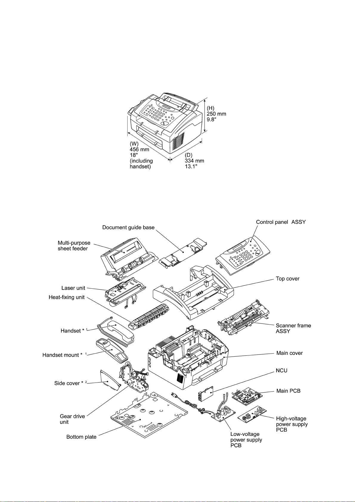
1.1 External Appearance and Weight
The figure below shows the equipment appearance and approximate dimensions.
Weight: Machine proper Approx. 7.2 kg
Machine (incl. drum unit & toner cartridge) Approx. 8.5 kg
In package Approx. 12 kg
1.2 Components
The equipment consists of the following major components:
I - 1
*1 Not provided on the FAX8060P/MFC9060.
2
*
Provided on the FAX8060P/MFC9060.
Page 8

2. SPECIFICATIONS
Model FAX2600 MFC4300 MFC4600
Color Gray 1495 Gray 1495 Gray 1495
FAX Yes Yes Yes
Modem Speed (bps) 14.4K (FAX Only) 14.4K (FAX Only) 14.4K (FAX Only)
CCITT Group G3 G3 G3
Coding Method MH/MR/MMR MH/MR/MMR MH/MR/MMR
Error Correction Mode (ECM) Yes Yes Yes
Transmission Speed (sec) 6 6 6
Gray Scale 64 64 64
Super Fine Yes Yes Yes
Smoothing Yes Yes Yes
Multi Resolution TX Yes Yes Yes
Input/Output Width 8.5" x 8.5" 8.5" x 8.5" 8.5" x 8.5"
ADF (pages) 20 20 20
LCD Size 16 x 1 16 x 1 16 x 1
Handset Yes Yes Yes
One-touch Dial 16 (8 x 2) 8 8
Speed Dial 30 30 30
Tel-Index Yes (Search) Yes (Search) Yes (Search)
Chain Dialing Yes Yes Yes
Contrast SL/Auto/SD SL/Auto/SD SL/Auto/SD
FAX/TEL Switch Yes Yes Yes
Distinctive Ringing Yes Yes Yes
Caller ID Yes (Call Waiting) Yes (Call Waiting) Yes (Call Waiting)
TAD Interface Yes Yes Yes
Next FAX Reservation Yes - Dual Access Yes - Dual Access Yes - Dual Access
DUAL ACCESS Yes Yes Yes
Help Yes Yes Yes
Coverpage Yes - Super Yes - Super Yes - Super
Polling Type Std/Seq Std/Seq Std/Seq
Delayed Timer Yes - up to 50 Yes - up to 50 Yes - up to 50
Broadcasting *
Call Reservation Yes Yes Yes
Page Memory (TX) *
Out-of-paper Reception *
Call Back Message Yes Yes Yes
Paging Yes Yes Yes
FAX Forwarding Yes Yes Yes
FAX Ret rieval Yes Yes Yes
Super Quickscan Yes Yes Yes
*1 The number of dials for broadcasting is the total of "One-touch dials (16/8)" + "Speed dial s (30)" + "Manual dials (50)".
*2 According to the Br other chart in st andard mode, MMR.
1
2
2
Yes (up to 96) Yes (up to 88) Yes (up to 88)
Max 1.3 MB (130 pages) Max 1.3 MB (130 pages) Max 1.3 MB (130 pages)
Max 1.3 MB (130 pages) Max 1.3 MB (130 pages) Max 1.3 MB (130 pages)
(Combined with Copy key)
(1/3)
I - 2
Page 9

Model FAX8060P MFC9060
Color Gray 1495 Gray 1495
FAX Yes Yes
Modem Speed (bps) 14.4K (FAX Only) 14.4K (FAX Only)
CCITT Group G3 G3
Coding Method MH/MR/MMR MH/MR/MMR
Error Correction Mode Yes Yes
Transmission Speed (sec) 6 6
Gray Scale 64 64
Super Fine Yes Yes
Smoothing Yes Yes
Multi Resolution TX Yes Yes
Input/Output Width 8.5" x 8.5" 8.5" x 8.5"
ADF (pages) 20 20
LCD Size 16 x 1 16 x 1
Handset No No
Duplex Speaker Phone No No
One-touch Dial 16 (8x2) 16 (8x2)
Speed Dial 30 30
Tel-Index Yes Yes
Chain Dialing Yes Yes
Contrast SL/Auto/SD SL/Auto/SD
FAX/TEL Switch Yes Yes
FAX/TEL OGM No No
Distinctive Ringing Yes (UK, DEN only) Yes (UK, DEN only)
Caller ID *
TAD Interface Yes Yes
Next FAX Reservation Yes - Dual access Yes - Dual access
DUAL ACCESS Yes Yes
Help Yes Yes
Coverpage Yes - Super Yes - Super
Polling Type Std/Seq/Del (Sec) Std/Seq/Del (Sec)
Password Check No No
Delayed Timer Yes (up to 50) Yes (up to 50)
Broadcasting Yes (up to 96) Yes (up to 96)
Call Reservation Yes Yes
Page Memory (TX) *
Out-of-paper Reception *
Call Back Message Yes Yes
*1 Call Wai ting Caller ID is not available.
*2 According to the Br other chart in st andard mode, MMR.
1
2
(up to 130 pages: MMR)
2
(up to 130 pages: MMR)
No No
Max. 1.3 MB
(up to 130 pages: MMR)
Max 1.3 MB
(up to 130 pages: MMR)
Max. 1.3 MB
Max 1.3MB
(1/3)
I - 3
Page 10

(2/3)
Model FAX2600 MFC4300 MFC4600
COPY Yes Yes Yes
dpi 203 x 391 203 x 391 203 x 391
Collating 99 99 99
Reduction/Enlarge 50, 75, 87, 93, 100, 120,
125, 150, 200%
Sort Yes (w/o Key) Yes (w/o Key) Yes (w/o Key)
PRINTER N/A Yes Yes
Engine/Type - YL2 YL2
PPM - 6 ppm 6 ppm
DPI (output resolution) - 600 x 600 600 x 600
Paper Capacity - 200 200
Emulation (Standard) - PCL4 PCL4
Standards - Windows GDI (600 x 600) Wi ndows GDI (600 x 600)
Memory (Typical) - 1 MB 1 MB
Memory (MIN.) - 600 KB 600 KB
Fonts Resident - - Fonts Disk Based - Yes - 35TT Yes - 35TT
Paper Handling - LTR, LGL, A4, B5, A5, OHP LTR, LGL, A4, B5, A5, OHP
Multi-Purpose Tray - Custom size
Toner Life (Starter) 1,000 pages with 5% black 1,000 pages with 5% black 1,000 pages with 5% black
Toner Life (Supply) 2,200 pages with 5% black 2,200 pages with 5% black 2,200 pages with 5% black
Drum Life Up To 20,000 pages
(20 pages/job)
Up To 8,000 pages
(1 page/job)
Utility Software - RPC RPC
Period to go in Sleep Mode - 0-99 0-99
Output size - LTR, LGL, A4, B5, A5 LTR, LGL, A4, B5, A5
Interface/Interface cable No/No Yes (Bi Centro)/No Yes (Bi Centro)/Yes
SCANNER N/A N/A Yes
Color/Mono - - Mono
dpi - - Opt. 200 x 400
Gray Scale - - 256
Twain - - Yes
Formats (Import) - - TIFF/BMP/PCX/DCX/BTF/
Formats (Export) - - TIFF/BMP/MAX/PDF
ADF (pages) - - 20
OCR - - Yes (ScanSoft: TextBridge)
50, 75, 87, 93, 100, 120,
125, 150, 200%
(2.75 x 5, 8.5 x 14)
Envelop
(DL/C5/CM10/Mona)
Up To 20,000 pages
(20 pages/job)
Up To 8,000 pages
(1 page/job)
50, 75, 87, 93, 100, 120,
125, 150, 200%
Custom size
(2.75 x 5, 8.5 x 14)
Envelop
(DL/C5/CM10/Mona)
Up To 20,000 pages
(20 pages/job)
Up To 8,000 pages
(1 page/job)
(Int. 600 X 600)
BTX/MAX/PDF
I - 4
Page 11

(2/3)
Model FAX8060P MFC9060
Super Quickscan No No
Mail box No No
Multi-Transmission No No
PRINTER N/A Yes
Engine/Type - YL (VA)
PPM - 6 ppm
DPI (output resolution) - 600 x 600
Paper Capacity - 200
Emulation - (Standard) - Windows GDI (600x600)
Memory (Typical) - 1 MB
Memory (MIN.) - 600 KB
Fonts Resident - Fonts Disk Based - Paper Handling - LTR, LGL, A4, B5, A5, OHP
Multi-Purpose Tray - Custom size
Support Windows OS
- Windows95/98 and
(Printer Driver)
Toner Life (Standard) 1,000 pages with 5% black 1,000 pages with 5% black
Toner Life (Supply) 2,200 pages with 5% black 2,200 pages with 5% black
Drum Life 20,000 pages (20 pages/job) 20,000 pages (20 pages/job)
8,000 pages (1 page/job) 8,000 pages (1 page/job)
Utility Software for DOS - Period to go in Sleep Mode 0-99 0-99
Output size (LTR, LGL, A4, B5, A5) LTR, LGL, A4, B5, A5
Optional LAN Board No No
Optional Mac Board No No
Interface connector No Yes (Bi Centro)
Interface cable No Yes *
SCANNER N/A Yes (TWAIN only)
Color/Mono - dpi - Gray Scale - Twain - Yes
Formats (Import) - Formats (Export) - ADF (pages) - OCR - -
*3 Only for GER, UK, FRA, AUS, IRE, and S.AF
(2.75x5, 8.5x14)
Envelop
(DL/C5/CM10/Mona)
NT4.0/2000 Driver with
Auto Installer Program
3
I - 5
Page 12

(3/3)
Model FAX2600 MFC4300 MFC4600
General
Energy Star Compliance Yes Yes Yes
Memory (Standard) 2MB 2MB 2MB
Memory (Opt Upgrade) N/A N/A N/A
Simultaneous Operation N/A Yes
Bundled Software
Applications
Printer Driver - Windows3.1x/95/98/ME,
Scanner (TWAIN)
Application
Viewer Application - No Yes
PC-FAX (Send/Receive) - No Yes (SMSI)
Internet Fax - No No
Automatic E-mail Printing - Yes (Brother) Yes (Brother)
Remote Setup - Yes (Brother) Yes (Brother)
N/A Yes Yes
- No Yes (Brother)
(PRINTER/FAX,
PRINTER/COPY)
NT 4.0/2000
Driver with Auto Installer
Program
Windows3.1x/95/98/ME,
Driver with Auto Installer
(ScanSoft: PaperPort 6.1)
Yes
(PRINTER/FAX,
PRINTER/SCAN,
PRINTER/COPY)
NT 4.0/2000
Program
I - 6
Page 13

(3/3)
Model FAX8060P MFC9060
COPY Yes Yes
dpi 203 x 391 203 x 391
Collating 99 99
Reduction/Enlarge 50, 75, 87, 93, 100, 120,
Sort Yes Yes
Message Center No No
OGM No No
ICM Recording Time No No
Paging No No
Fax & Voice Mail Box No No
Fax & Voice on Demand No No
FAX Forwarding Yes Yes
FAX Ret rieval Yes Yes
General
Memory (Standard: Physical) 2MB 2MB
Memory (Opt. Upgrade) No No
Simultaneous Operation N/A Yes
Data Modem No No
Remote Diagnostics Yes Yes
Memory Backup No No
Memory Security No No
Pin TX LOCK Yes Yes
Bundled Software
Applications
Printer Driver - Yes (Brother)
PC-FAX (Send/Receive) - Scanner Application - TWAIN (Brother)
Viewer Application - Yes (PaperPort: ScanSoft)
Network Application No No
Class1 No No
125, 150, 200%
N/A Yes
50, 75, 87, 93, 100, 120,
125, 150, 200%
(PRINTER/FAX,
PRINTER/SCANNER,
PRINTER/COPY)
I - 7
Page 14

CHAPTER II.
INSTALLATION
Page 15

CHAPTER II. INSTALLATION
CONTENTS
1. INSTALLING THE UPDATE DATA TO THE FACSIMILE EQUIPMENT................. II-1
Page 16
1. INSTALLING THE UPDATE DATA TO THE FACSIMILE EQUIPMENT
If the program version is updated or the main PCB is r eplaced, install the update program onto the
flash ROM of the main PCB.
The program inst allation requires a PC/AT-compatible c omputer (which is capable of r unning MSDOS or its compatible OS).
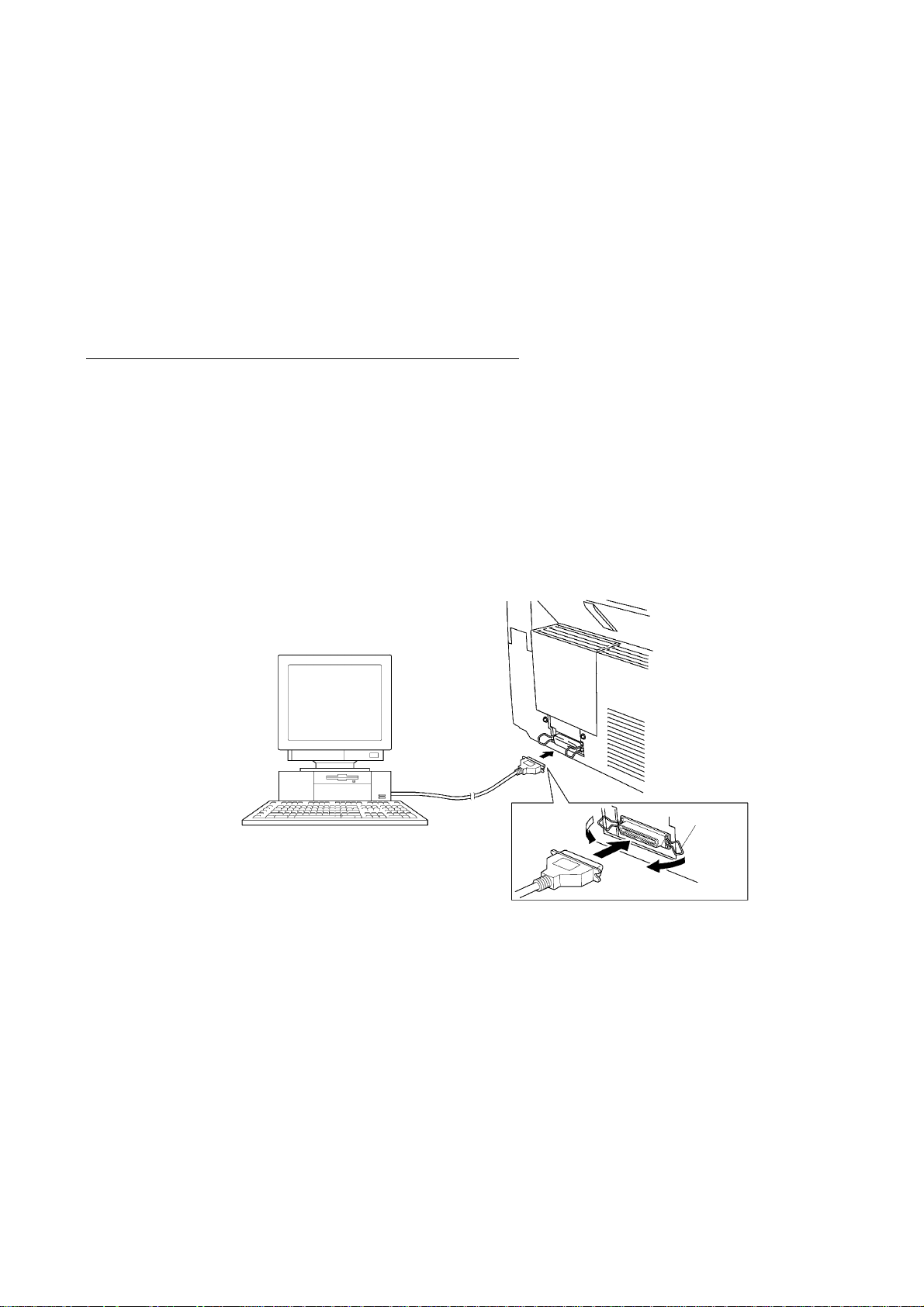
Connecting the facsimile equipment to your computer
(1) Make sure that the equipment's power cord is unplugged from a wall socket.
(2) Make sure that your computer is powered off.
(3) Connect the interface cable to the parallel interf ace port on the back of the equipment and
secure it with the lock wires.
(4) Connect the other end of the interface cable to the printer por t of your com puter and sec ure it
with the two screws.
(5) Power on your computer.
(6) Plug the equipment's power cord into a wall socket.
Host computer
Interface cable
Lock
wires
II - 1
Page 17

Installing the update data onto the flash ROM of the facsimile equipment
NOTE: The following is an installation procedure example on a PC that is running Windows 95/98.
(1) Copy the update data and transfer utility onto the desired directory of the hard disk.
e.g., C:\UPDATE
(2) Click the Start button, point to Program s, and then click MS-DOS Prompt to open an MS-
DOS window.
(3) Type the drive letter where the update data and transfer utility are located. In the above
example, type C:\ from the command line and press the ENTER key.
Then type CD UPDATE and press the ENTER key.
(4) Check that your computer is connected with the facsimile equipment correctly.
(5) To start the transfer utility transmitting the update data to the flash ROM of the facsimile
equipment, type the following:
ICEN filename /b
Then press the ENTER key.
During downloading, the equipment beeps intermittently.
Upon completion of the downloading, the equipment beeps continuously.
NOTE: If the facsimile equipment cannot return to the standby state after completion of
downloading, turn the power off and on.
II - 2
Page 18

CHAPTER III.
THEORY OF OPERATION
Page 19

CHAPTER III. THEORY OF OPERATION
CONTENTS
1. OVERVIEW ............................................................................................................... III-1
2. MECHANISMS.......................................................................................................... III-2
2.1 Scanner Mechanism ......................................................................................... III-3
2.1.1 Document feeding and ejecting mechanism............................................. III-3
2.1.2 Scanner..................................................................................................... III-3
2.2 Laser Printing Mechanism ................................................................................ III-4
2.2.1 Paper pulling-in, registration, feeding, and ejecting mechanism............... III-4
2.2.2 Print process mechanism.......................................................................... III-6
2.2.3 Heat-fixing mechanism .............................................................................. III-7
2.3 Sensors and Actuators...................................................................................... III-8
3. CONTROL ELECTRONICS...................................................................................... III-10
3.1 Configuration..................................................................................................... III-10
Page 20
1. OVERVIEW
III - 1
*Not provided on the FAX8060P/MFC9060.
Page 21
2. MECHANISMS
The facsimile equipment is classified into the following mechanisms:
SCANNER MECHANISM - Document feeding and ejecting mechanism
LASER PRINTING MECHANISM - Paper pulling-in, registration, feeding, and ejecting
SENSORS AND ACTUATORS
- Document scanning mechanism
mechanisms
- Print process mechanism (consisting of charging,
exposing, developing, transferring, and erasing
processes)
- Heat-fixing mechanism
Document feeding and
ejecting mechanism
SCANNER
Document scanning
mechanism
MECHANISM
Paper pulling-in and
registration mechanism
Print process
mechanism
LASER PRINTING MECHANISM
III - 2
Paper ejecting mechanism
Heat-fixing
mechanism
With paper feeding
mechanism
Page 22

2.1 Scanner Mechanism
2.1.1 Document feeding and ejecting mechanism
This mechanis m consists of the document s tacker, automatic docum ent feeder (ADF), docum ent
ejection roller ASSY, and document sensors. (For details about the sensors, refer to Section 2.3.)
If the operator sets documents on the document stacker and starts the scanning operation, the
scanner motor rotates so that the ADF (which consists of the separation roller and ADF parts) feeds
those documents into the equipment, starting from the bottom sheet to the top, page by page.
Each document advances with the docum ent f eed roller ASSY to the scanner , and then it is fed out
of the equipment with the document ejection roller ASSY.
2.1.2 Scanner
The scanner uses a contact image sens or (CIS) unit which consists of an LED array illuminating
documents, a self-focus lens array collecting the reflected light, a CIS PCB carrying out
photoelectric conversion to output picture elem ent data, and a cover glass on which a docum ent
advances. W hen the doc ument passes between the document pr ess ur e bar and the c over glass , it
is scanned.
III - 3
Page 23
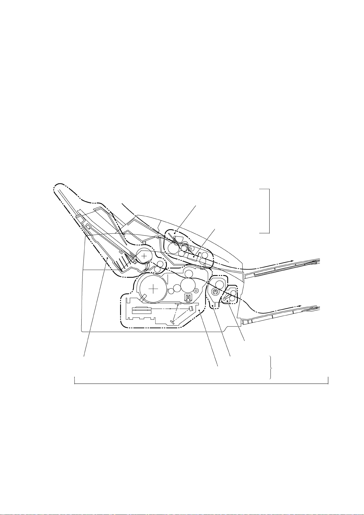
2.2 Laser Printing Mechanism
2.2.1 Paper pulling-in, registration, feeding, and ejecting mechanism
III - 4
Page 24
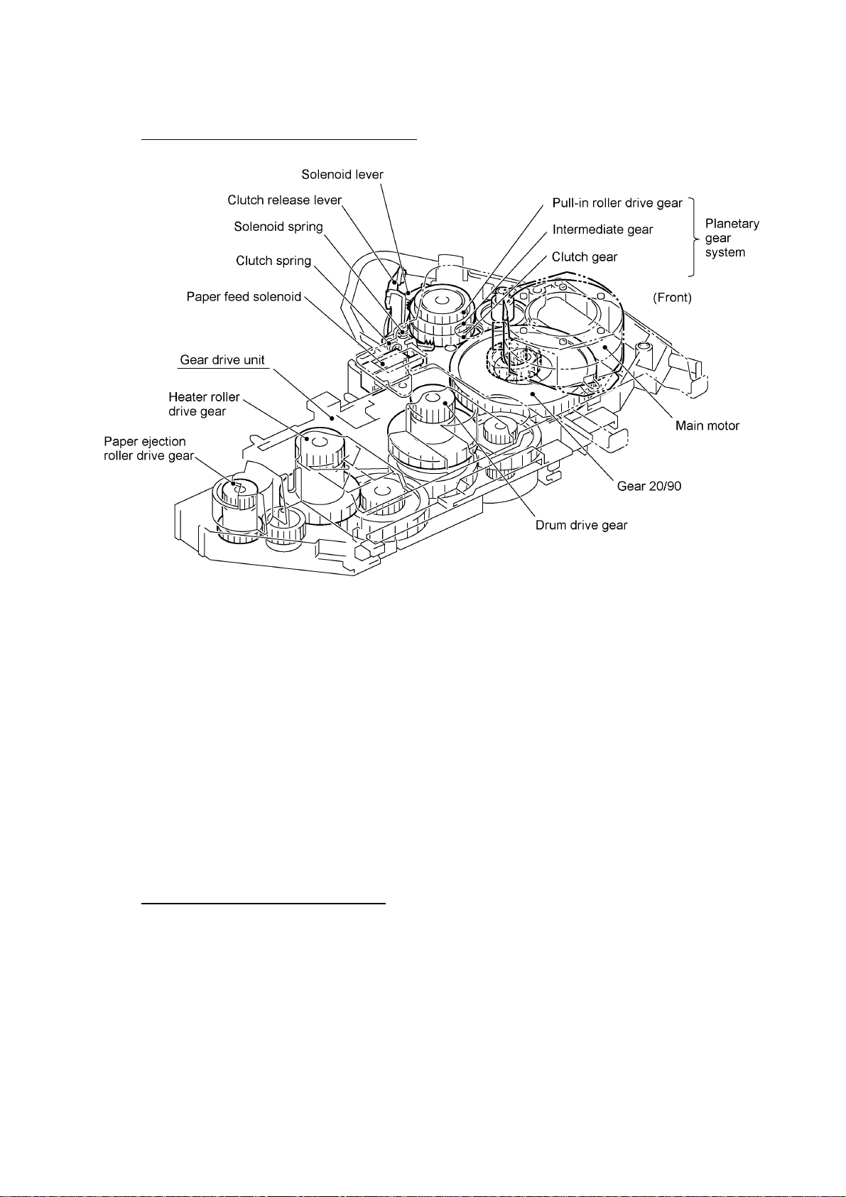
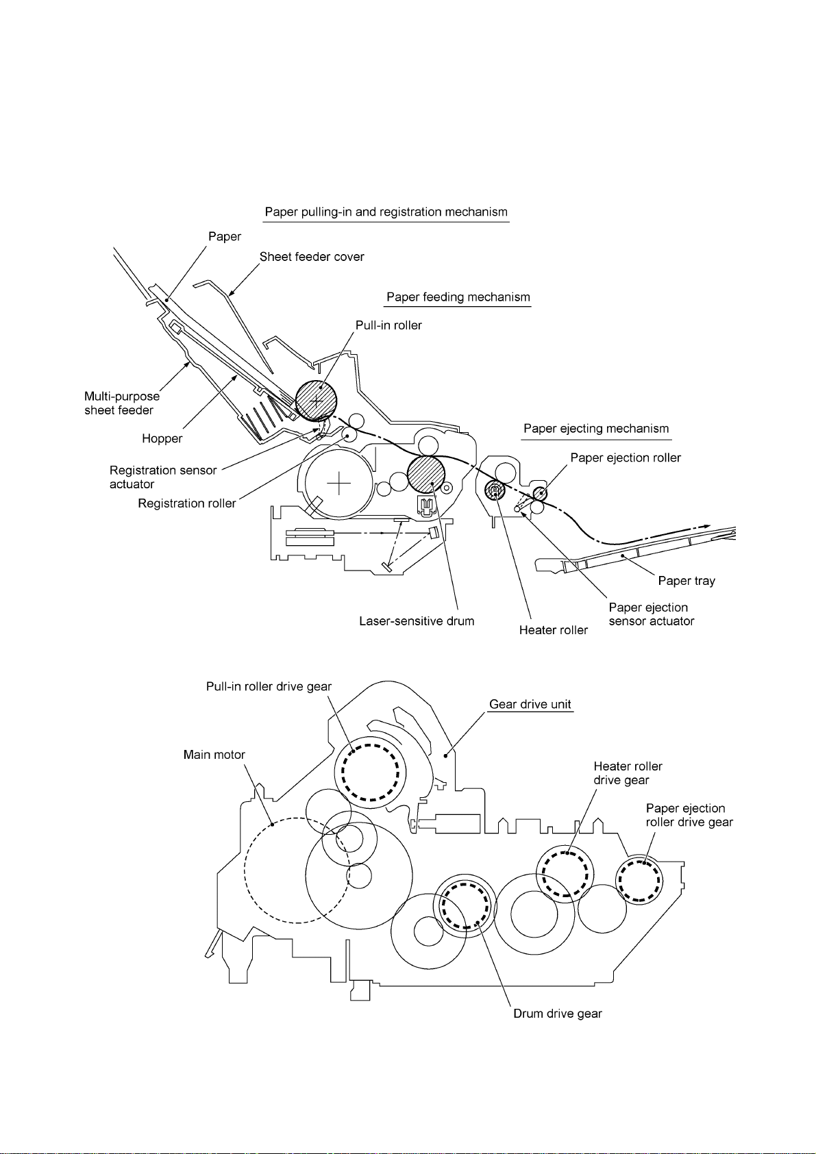
Paper pulling-in and registration mechanism
The paper pulling-in and registration m echanism consis ts of the pull-in roller gear (incorporated in
the multi-purpose sheet f eeder), planetary gear system, paper f eed solenoid, s olenoid lever, c lutch
release lever, and registration sensor. (For the details about the sensor, refer to Section 2.3.)
If the main motor rotates clockwise, the rotation is transmitted to the intermediate gear of the
planetary gear system. As the intermediate gear rotates, the pull-in roller drive gear also rotates
since the clutch gear is locked by the solenoid lever and the clutch release lever. Ac cordingly, the
pull-in roller in the multi-purpos e sheet feeder rotates to pull in paper into the equipm ent, a s heet at
a time.
If the paper feed solenoid is retracted and the clutch release lever is operated according to the c am
profile of the pull-in roller gear s o as to releas e the clutch gear, the clutc h gear rotates and the pullin roller drive gear does not rotate. In this way, the clutch gear switches the transmission of the
motor rotation to the pull-in roller drive gear on and off.
The solenoid on/off timing and the clutch release lever timing allow this mechanism to pull in a
sheet and register it against the registration roller.
Paper feeding and ejecting mechanism
If the main motor rotates clock wise, the rotation is transmitted via the gear train to the drum drive
gear, heater roller drive gear, and paper ejection roller drive gear.
After the paper passes through the heat-fixing process, it will be ejected onto the paper tray.
If the leading edge of the paper pushes up the actuator of the paper ejection sensor, the
photosensor becomes opened, s ignaling the start of paper ejec tion. If the trailing edge has pass ed
through the sensor actuator, the sensor becomes closed, signaling the completion of paper
ejection. Then, the main motor stops rotation.
III - 5
Page 25
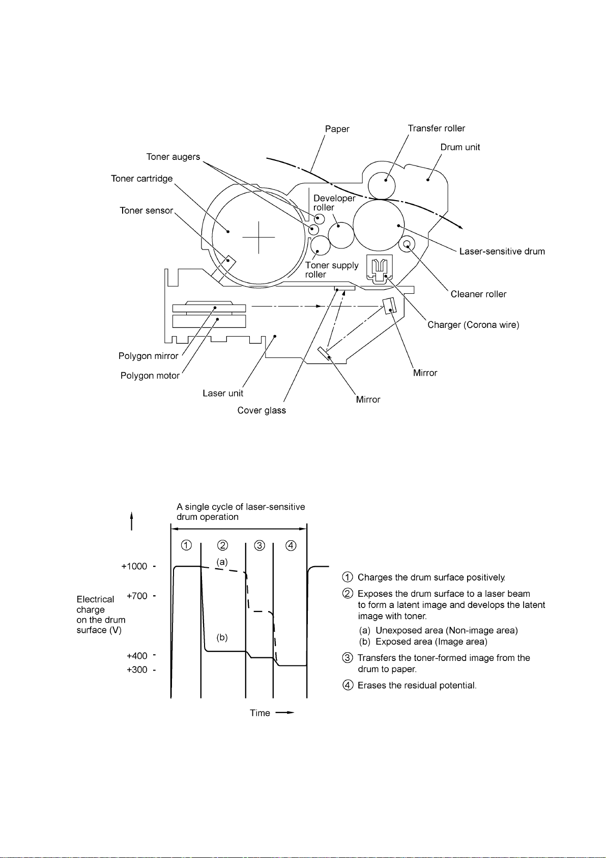
2.2.2 Print process mechanism
The print process unit works with laser beam, electrical charges, and toner. The graph below
shows the transition of electrical c harge on the surface of the las er-sensitive drum thr ough the five
processes: charging, exposing, developing, transferring, and erasing processes.
III - 6
Page 26
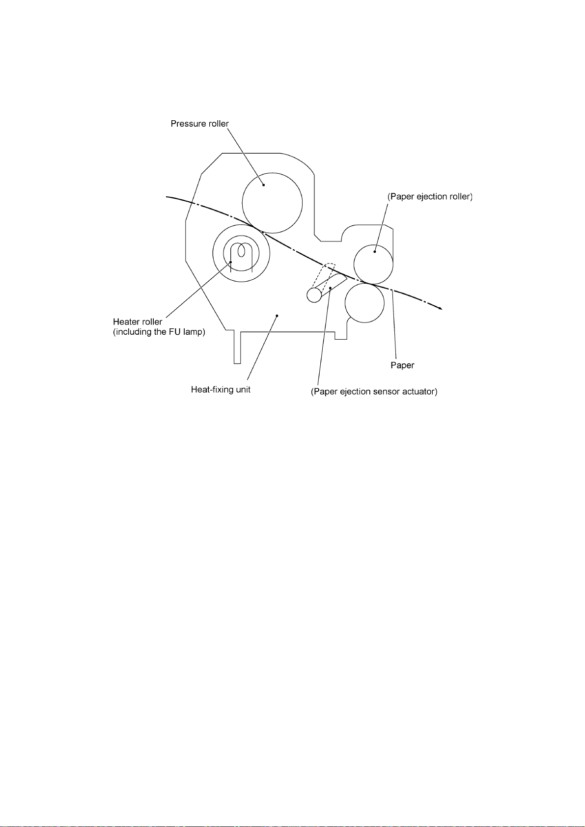
2.2.3 Heat-fixing mechanism
As the paper passes between the heater roller and the press ure roller in the heat-fixing unit, the
heater roller fuses the toner on the paper.
III - 7
Page 27
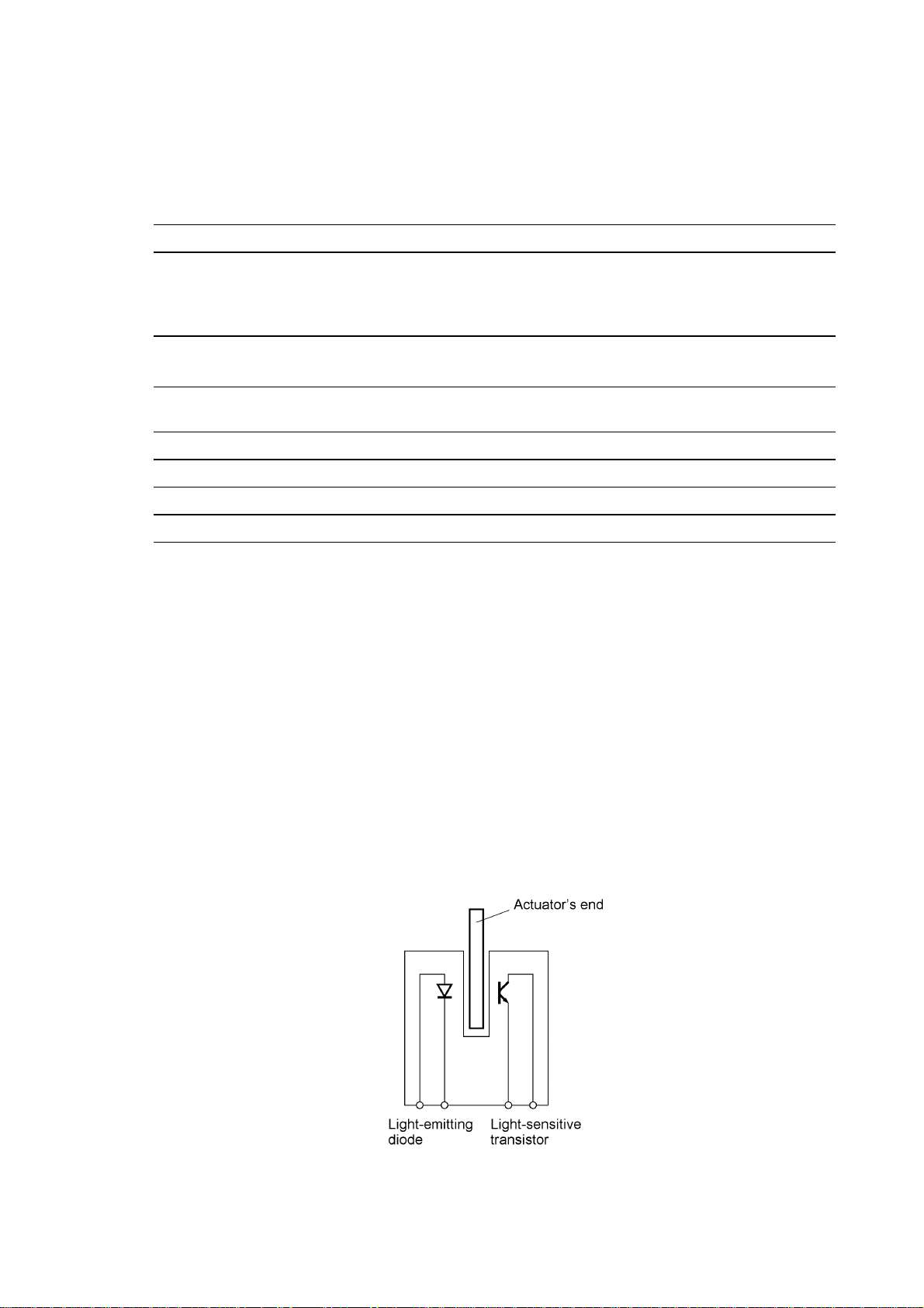
2.3 Sensors and Actuators
This equipment has ten sensors: six photosensors, two thermisters and a mechanical switch as
described below.
Sensor name Type Located on
Document front sensor Photosensor Control panel PCB ASSY
Document rear sensor Photosensor Control panel PCB ASSY
Top cover sensor Photosensor Main PCB
Registration sensor Photosensor Main PCB
Paper ejection sensor Photosensor High-voltage power supply
Toner sensor Photosensor Toner sensor PCB
Toner thermister Thermister Toner sensor PCB
Heater thermister Thermister Heat-fixing unit
Hook switch* Mechanical switch Hook switch PCB*
• Document front sensor which detects the presence of documents.
• Document rear sensor which detects the leading and tr ailing edges of pages to tell the control
circuitry when the leading edge of a new page has reached the starting position and when the
scan for that page is over.
• Top cover sensor which detects whether the top cover is closed.
• Registration sensor which detects the leading and trailing edges of paper, which allows the
controller to determine the registration timing and check paper jam.
• Paper ejection sensor which detects whether the recording paper goes out of the equipment.
• Toner sensor which detects whether there is toner or a toner cartridge is loaded.
• Toner thermister which detects the ambient temperature of the toner cartridge.
• Heater thermister which detects the temperature of the heater roller of the fixing unit.
• Hook switch* which detects whether the handset is placed on the handset mount.
(Document sensor PCB)
(Document sensor PCB)
PCB
*Not provided on the FAX8060P/MFC9060.
These photosensors are a photointer rupter consisting of a light- emitting diode and a light-sens itive
transistor. Each of them has an actuator separately arranged as shown on the next page.
III - 8
Page 28
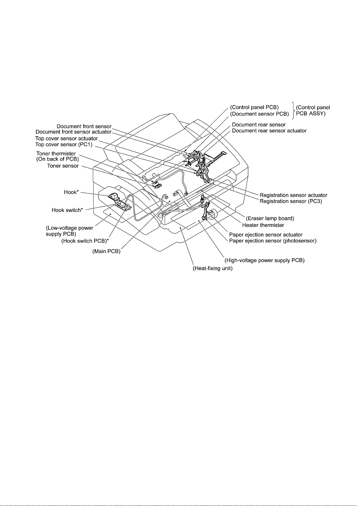
Location of Sensors and Actuators
*Not provided on the FAX8060P/MFC9060.
III - 9
Page 29
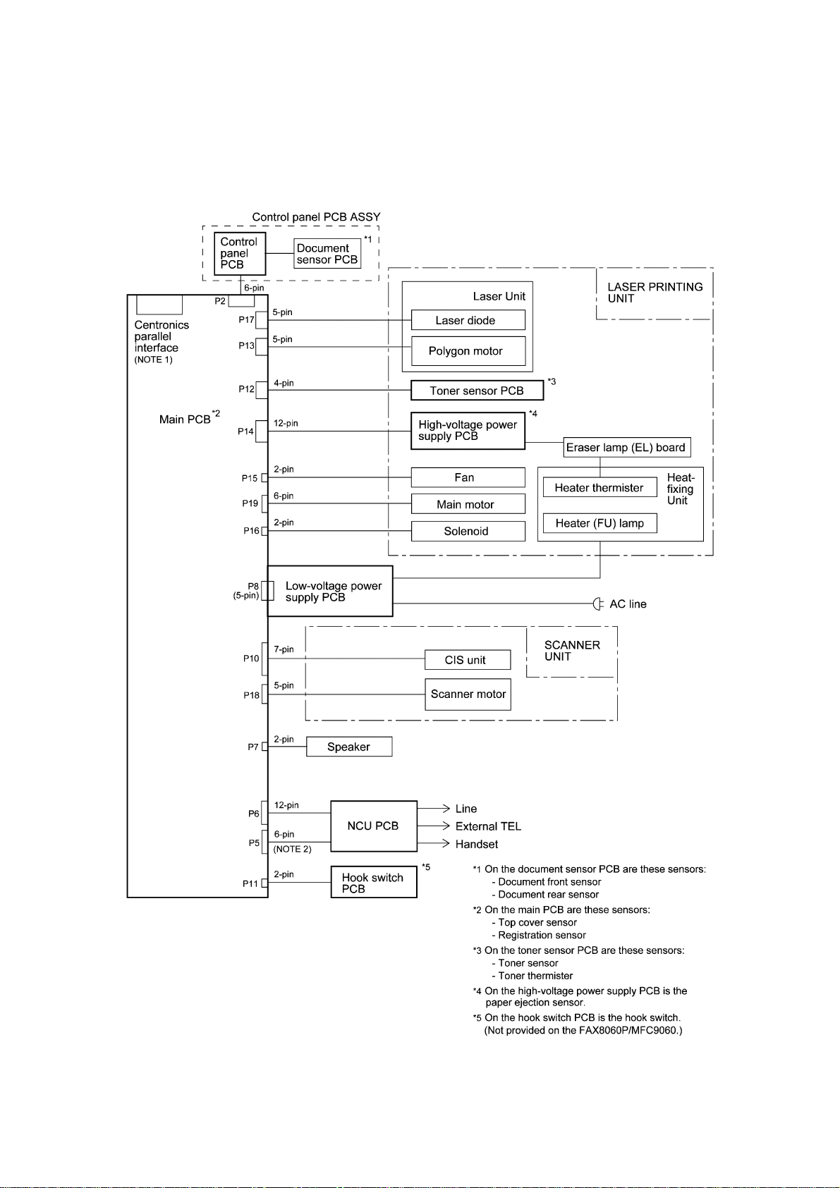
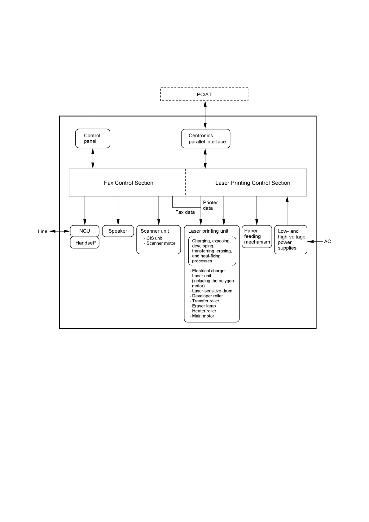
3. CONTROL ELECTRONICS
3.1 Configuration
The hardware configuration of the facsimile equipment is shown below.
(NOTE 1) Not provided on the FA X2600/FAX8060P
(NOTE 2) Provided on the E uropean, Australian, Indonesian,
and Asian versions.
Configuration of Facsimile Equipment
III - 10
Page 30

CHAPTER IV.
DISASSEMBLY/REASSEMBLY AND
LUBRICATION
Page 31

CHAPTER IV. DISASSEMBLY/REASSEMBLY AND LUBRICATION
CONTENTS
1. DISASSEMBLY/REASSEMBLY............................................................................... IV-1
Safety Precautions.................................................................................................. IV-1
Tightening Torque List ............................................................................................ IV-2
Preparation.............................................................................................................. IV-3
How to Access the Object Component................................................................... IV-3
Disassembly Order Flow......................................................................................... IV-4
1.1 ROM Cover and Option Cover ........................................................................... IV-5
1.2 Multi-purpose Sheet Feeder............................................................................... IV-6
1.3 Document Guide Base ....................................................................................... IV-7
1.4 Control Panel ASSY ........................................................................................... IV-8
1.5 Panel Rear Cover and Control Panel ................................................................. IV-9
1.6 Document Feed Roller ASSY and Document Ejection Roller ASSY.................. IV-12
1.7 Scanner Frame ASSY ........................................................................................ IV-13
1.8 Top Cover........................................................................................................... IV-20
1.9 Handset Mount and Hook Switch PCB
Side Cover (for FAX8060P/MFC9060) ....................................................................... IV-23
1.10 Heat-fixing Unit, FU Lamp, and Paper Ejection Sensor Actuator....................... IV-25
1.11 Laser Unit and Toner Sensor PCB..................................................................... IV-27
1.12 Bottom Plate....................................................................................................... IV-28
1.13 Low-voltage Power Supply PCB......................................................................... IV-30
1.14 Main PCB ........................................................................................................... IV-31
1.15 High-voltage Power Supply PCB........................................................................ IV-34
1.16 Fan ..................................................................................................................... IV-35
1.17 Registration Sensor Actuator and Top Cover Sensor Actuator.......................... IV-36
1.18 Speaker.............................................................................................................. IV-36
1.19 Gear Drive Unit................................................................................................... IV-37
1.20 NCU PCB ........................................................................................................... IV-39
1.21 Scanner Grounding Plate................................................................................... IV-41
1.22 EL (Eraser Lamp) Board .................................................................................... IV-42
1.23 Cleaning of High-voltage Contacts and Grounding Contacts............................. IV-43
(for models except FAX8060P/MFC9060)
i
Page 32

2. LUBRICATION.......................................................................................................... IV-44
[ 1 ] Document feed roller ASSY and document ejection roller ASSY............... IV-44
[ 2 ] Control panel locks..................................................................................... IV-45
[ 3 ] Scanner frame ASSY and separation roller gear ....................................... IV-45
[ 4 ] Top cover lock spring................................................................................. IV-46
[ 5 ] Gear drive unit............................................................................................ IV-46
ii
Page 33

1. DISASSEMBLY/REASSEMBLY
Safety Precautions
To prevent the creation of sec ondary problems by mishandling, observe the following precautions
during maintenance work.
(1) Unplug the power cord from the power outlet before replacing parts or units. When having
access to the power supply, be sure to unplug the power cord from the power outlet.
(2) W hen s ervic ing the optic al system of the las er printing unit, be c ar ef ul not to plac e s c rewdriver s
or other reflective objects in the path of the laser beam. Be sure to take off any personal
accessories such as wrist watches and rings before work ing on the printer. A reflected beam,
though invisible, can permanently damage your eyes.
(3) If the equipment has been printing, allow the heat-fixing unit suff icient time to c ool down before
starting maintenance jobs. It is HOT!
(4) Be careful not to lose screws, washers, or other parts removed for parts replacement.
(5) Do not remove gears from the document feed roller ASSY or ejection roller ASSY if at all
possible. Once removed, they will become unusable and new gears will have to be put back in.
(6) When using solder ing irons and other heat-generating tools, take car e not to dam age the res in
parts such as wires, PCBs, and covers.
(7) Before handling the PCBs, touch a m etal por tion of the equipment to discharge static elec tric ity;
otherwise, the electronic parts may be damaged due to the electricity charged in your body.
(8) When transporting PCBs, be sure to wrap them in conductive sheets such as aluminum foil.
(9) Be sure to reinsert self-tapping screws correctly, if removed.
(10) Tighten screws to the torque values listed on the next page.
(11) When connecting or disconnecting cable connectors, hold the connector bodies not the cables.
If the connector has a lock, always slide the connector lock to unlock it.
(12) Before reassembly, apply the specified lubricant to the specified points. (Refer to Section 2 in
this chapter.)
(13) After repairs, check not only the repaired portion but also that the connectors and other related
portions function properly before operation checks.
IV - 1
Page 34

Tightening Torque List
Location Screw type Q'ty Tightening torque
N•m (kgf•cm)
Option cover Screw, pan (washer) M3x8DB 2 0.39 ±0.10 (4 ±1)
ADF parts Taptite, pan (washer) B M3x6 1 0.39 ±0.10 (4 ±1)
Panel rear cover Taptite, cup B M3x8 2 0.59 ±0.10 (6 ±1)
Scanner frame ASSY Taptite, cup B M3x10 2 0.88 ±0.20 (9 ±2)
Scanner motor Screw, pan (washer) M3x6DA 1 0.69 ±0.20 (7 ±2)
Scanner grounding leaf spring Taptite, cup S M3x6 1 0.69 ±0.20 (7 ±2)
CIS shield plate Taptite, cup S M3x6 1 0.69 ±0.20 (7 ±2)
Pinch roller leaf spring Taptite, cup B M3x8 1 0.78 ±0.20 (8 ±2)
Control panel locks Taptite, cup B M3x8 2 0.78 ±0.20 (8 ±2)
Scanner drive unit Taptite, cup B M3x8 1 0.78 ±0.20 (8 ±2)
Taptite, cup B M3x10 1 0.78 ±0.20 (8 ±2)
Top cover stopper Taptite, cup S M3x6 2 0.78 ±0.20 (8 ±2)
Hinges on top cover Taptite, bind B M4x12 4 0.98 ±0.20 (10 ±2)
Hinges on main cover Taptite, cup B M4x12 4 0.98 ±0.20 (10 ±2)
Handset mount Taptite, cup B M3x10 2 0.78 ±0.20 (8 ±2)
Heat-fixing unit Taptite, bind B M4x12 1 0.98 ±0.20 (10 ±2)
Laser unit Taptite, bind B M4x12 3 0.78 ±0.20 (8 ±2)
Toner sensor PCB Taptite, cup B M3x8 1 0.59 ±0.20 (6 ±2)
Bottom plate Taptite, bind B M4x12 7 0.98 ±0.20 (10 ±2)
Taptite, cup S M3x6 3 0.78 ±0.20 (8 ±2)
AC grounding wire Screw, pan (washer) M4x8DB 1 0.59 ±0.20 (6 ±2)
Interface connector Screw, pan M3x6 2 0.78 ±0.20 (8 ±2)
Low-voltage power supply PCB Taptite, cup S M3x6 1 0.78 ±0.20 (8 ±2)
Main PCB Taptite, bind B M4x12 1 0.98 ±0.20 (10 ±2)
High-voltage power supply PCB Taptite, bind B M4x12 1 0.98 ±0.20 (10 ±2)
Gear drive unit Taptite, cup B M4x20 3 1.18 ±0.20 (12 ±2)
Main motor Taptite, cup S M3x8 2 0.78 ±0.20 (8 ±2)
NCU bracket Taptite, bind B M4x12 1 0.98 ±0.20 (10 ±2)
NCU PCB Taptite , cup S M3x6 1 0.78 ±0.20 (8 ±2)
Scanner grounding plate Taptite, cup B M3x8 1 0.59 ±0.20 (6 ±2)
IV - 2
Page 35

Preparation
Prior to proceeding to the disassembly procedure,
(1) Unplug
- the modular jack of the telephone line,
- the modular jack of the curled cord (and remove the handset),
- the PC interface cable, and
- the modular jack of an external telephone set if connected. (Not shown below.)
(2) Remove
- the paper wire extension,
- the document wire extension,
- the document tray,
- the paper tray, and
- the drum unit (with the toner cartridge loaded)
How to Access the Object Component
• On the next page is a disassembly order flow which helps you access the object components.
To remove the gear drive unit, f or example, first f ind it on the flow and learn its num ber (
this case). You need to remove parts num bered
gear drive unit.
• Unless otherwise specified, the disassembled parts or components should be reassembled in
the reverse order of removal.
IV - 3
(*Not provided on the FAX8060P/MFC9060)
, , , , , and so as to access the
in
Page 36

Disassembly Order Flow
IV - 4
Page 37

1.1 ROM Cover and Option Cover
(1) As shown below, push down section "a" of the ROM cover and tilt it to the rear.
(2) T ake off the option cover from the rear of the main cover by removing two screws "a." T he
grounding wire also comes free.
IV - 5
Page 38

1.2 Multi-purpose Sheet Feeder
(1) Open the top cover.
(2) Rem ove one of two screws from each of right and left top cover stoppers, and then fully open
the top cover.
(3) Pull either one of the right and lef t tabs pr ovided on the m ain cover outwards and s lightly lift up
the multi-purpose sheet feeder, then release the other end of the sheet feeder also.
Reassembling Notes
• When reinstalling the m ulti-purpose sheet feeder, f it the front end over the bosses provided on
the main cover and then push down the rear end.
IV - 6
Page 39

1.3 Document Guide Base
(1) Turn up the document guide base towards you.
(2) Push the right or left end of the document guide base inwards and take it off.
IV - 7
Page 40

1.4 Control Panel ASSY
(1) Slightly open the control panel ASSY.
(2) Push the right and left arms of the control panel ASSY outwards (in the direction of arrow )
with your thumbs and open the control panel ASSY further (arrow ) to unhook those arms
from bosses “x” provided on the scanner frame ASSY. Then slide the control panel ASSY to
the front (arrow ) to release its bosses “y” from the grooves of the scanner frame ASSY.
(3) Slightly lift up the control panel ASSY and disconnec t the panel-m ain harness from the control
panel PCB.
IV - 8
Page 41

1.5 Panel Rear Cover and Control Panel
(1) Place the control panel ASSY upside down.
If you do not need to remove the ADF parts , anti-static brush, shield film , document pressure
bar, or document rear sensor actuator, skip to step (6).
(2) To remove the ADF parts ( spring plates, separation rubber and anti-vibration r ubber), remove
the screw.
(3) To replace the anti-static brush and shield film, remove them.
NOTE: Once removed, the anti-static brush and shield film will become unusable and new
parts will have to be put back in.
(4) T o remove the document press ure bar, pull either of supports "a" provided on the panel rear
cover outwards and then lift the pressure bar up and towards the r ear to release the thr ee tabs
from the cutouts provided in the panel rear cover. The spring also comes off.
(5) To remove the document rear sensor actuator, pull either of supports "b" on the panel rear
cover outwards.
IV - 9
Page 42

(6) Remove the two screws from the panel rear cover.
(7) Unhook the panel rear cover from eight "X" latches provided on the contr ol panel and lif t up the
panel rear cover.
(8) Fully turn the document front sensor actuator to the rear and lift it up.
(9) Unhook the document sensor PCB from two "Y" latches.
(10) Unhook the control panel PCB from three "Z" latches.
(11) Slightly lift up the control panel PCB, then unlock the LCD cable connector and disconnect the
LCD flat cable. Next, unlock the FPC key connector and disconnect the FPC key.
IV - 10
Page 43

(12) As shown below, pull the clamps outwards to release the LCD and take out the LCD while
pulling the LCD flat cable gently.
NOTE: Do not take out the LCD except when the LCD is defective and requires replacement.
Reassembling Notes
• Before reinstalling the LCD to the control panel, wipe fingerprints or dust off the LCD surface
and control panel window with a soft cloth.
• A new LCD is covered with a protection sheet. Before installing it, remove the protection sheet.
IV - 11
Page 44

1.6 Document Feed Roller ASSY and Document Ejection Roller ASSY
(1) Lightly push down arm rib "a" and shift the document feed roller ASSY to the right and
upwards.
(2) Lightly push down arm rib "b" and shift the document ejection roller ASSY to the right and
upwards, without removing the shield film.
NOTE: Take care not to break the arm ribs. They may easily break.
Reassembling Notes
• Make sure that the shield film is on the docum ent ejection roller gear and not bent down by that
gear.
• Once removed, the shield film will become unusable and new one will have to be put back in.
IV - 12
Page 45

1.7 Scanner Frame ASSY
(1) You can rem ove the f ollowing parts fr om the top of the s canner fr am e ASSY without tak ing out
the ASSY from the top cover.
• CIS film
• Shield film
• CIS unit (shown on the next page). Lightly pull up the arm, move the CIS unit to the left,
and lift up the right edge of the CIS unit. While holding up the CIS unit, disconnect the CIS
harness.
• CIS leaf springs (shown on the next page)
NOTE: Once removed, the CIS film and s hield film will become unusable and new ones will
have to be put back in.
IV - 13
Page 46

(2) Open the top cover.
(3) Disconnect the scanner motor harness from the scanner motor ASSY without removing the
shield film.
IV - 14
Page 47

(4) Close the top cover.
(5) Remove the two screws from the scanner frame ASSY.
(6) Lif t up the rear edge of the scanner frame ASSY to releas e the three pawls provided on the
front end from the top cover, then hold up the ASSY and disconnect the CIS harness (if the CIS
is mounted).
(7) Take off the grounding terminal by removing the screw.
IV - 15
Page 48

(8) Turn the scanner frame ASSY upside down.
(9) Rem ove the screw from the scanner motor and turn the motor clock wise to release from the
latch.
(10) Take off the scanner grounding leaf spring by removing the screw.
(11) Take off the CIS shield plate by removing the screw.
(12) Remove the pinch roller leaf spring, pinch rollers and shaft.
(13) Remove the control panel locks (leaf springs) by removing the screws.
IV - 16
Page 49

(14) Remove the pressure roller leaf spr ings by pulling them in the direction of arrows and in
this order as shown below. Then remove the pressure rollers and shaft.
(15) Slightly push down the arm (in the direction of arrow ) and shift the separation roller gear to
the right (arrow ) when viewed from the rear. Then shift the separation roller to the right
(arrow ) and take it up.
IV - 17
Page 50

(16) Take off the scanner drive unit by removing the two screws. T he separation roller gear also
comes off.
(17) Push down the CIS side spring to release it from the latch, then pull it out to the right (when
viewed from the rear).
IV - 18
Page 51

Reassembling Notes
• When reinstalling the scanner motor , fit it in the latch provided on the scanner frame with the
connector facing up and then secure it with the screw. (See page IV-16.)
• When setting the scanner frame ASSY back into place,
- secure the grounding terminal to the scanner frame ASSY with the screw and route the
grounding wire around boss "x" (as shown on page IV-15),
- route the CIS harness through the scanner fram e ASSY (or connect the CIS harness to the
CIS unit if mounted),
- route the panel-main harness through the cutout provided in the scanner frame ASSY.
• When reinstalling the CIS unit, f irs t c onnec t the CIS harnes s , inse rt the lef t end under the ar m of
the scanner frame, put the CIS unit into the scanner frame, and move it to right (see the
illustration given on page IV-14).
• When attaching the CIS film , align the right, lef t and r ear edges of the c utout with those provided
in the scanner frame and fit its two tabs into the scanner frame, as illustrated on page IV-13.
• When connecting the scanner motor harness to the scanner motor connector, tak e care not to
bend the shield film.
• Once removed, the shield film becomes unusable and a new part will have to be put back in.
IV - 19
Page 52

1.8 Top Cover
(1) Open the top cover.
(2) Rem ove one of two screws from each of right and left top cover stoppers, and then fully open
the top cover.
(3) Pull the panel-main harness and CIS harness towards you.
(4) Rem ove the adhesive tape and pull the scanner motor harness and grounding wire towards
you.
IV - 20
Page 53

(5) Remove the four screws from the hinges R and L.
(6) Slightly lift up the top cover to release the bosses from the hinges and take it off to the rear.
(7) Remove the harness support sponges and take out the harnesses from the top cover.
IV - 21
Page 54

(8) Rem ove the two screws from each of the hinges R and L. The top cover stoppers also come
off.
Reassembling Notes
• When setting each hinge back into place, fit its tab in section "x" provided on the main cover.
• As illustrated on the previous page, route the scanner motor harness and grounding wire
through hooks "A1" of the top cover and through hooks "A2" of the main cover, and then fix them
with the support sponge. Route the panel-main harness and CIS har ness thr ough hook s "B1" of
the top cover and through hooks "B2" of the main cover, and then fix them with the support
sponge.
• When connecting the scanner motor harness to the scanner motor connector, tak e care not to
bend the shield film.
• Once removed, the shield film becomes unusable and a new part will have to be put back in.
IV - 22
Page 55

1.9 Handset Mount and Hook Switch PCB (for models except FAX8060P/MFC9060) Side Cover (for FAX8060P/MFC9060)
(1) Open the top cover.
(2) Rem ove one of two screws from each of right and left top cover stoppers, then fully open the
top cover.
(3) Remove the two screws from the handset mount* or side cover**.
(4) T wist the handset m ount* or side cover** s o that it tilts over to the left and its upper end works
out of the bosses provided on the main cover.
NOTE: Do not pull the handset mount* away from the m ain c over. T he hook switch harness*
is connected to the main PCB in the main cover.
*For models except the FAX8060P/MFC9060
**For the FAX8060P/MFC9060
IV - 23
Page 56

(5) Dis assem ble the handset mount by unhooking two latches "a" of the upper handset m ount with
a flat screwdriver.
(6) Remove the hook switch PCB ASSY by unhooking latch "b."
(7) Disconnect the hook switch harness from the hook switch PCB.
Reassembling Notes
• When assembling the upper and lower handset mounts, route the hook switch harness
underneath the hook switch PCB and through the cutout as shown above. Take care not to
pinch the harness between the upper and lower mounts.
IV - 24
Page 57

1.10 Heat-fixing Unit, FU Lamp, and Paper Ejection Sensor Actuator
(1) Open the top cover.
(2) Rem ove one of two screws from each of right and left top cover stoppers, then fully open the
top cover.
(3) Remove screw "a."
(4) Lif t the left end of the heat-fixing unit up and to the left to release the right-hand boss fr om the
main cover, hold it up, and disconnect the heater harnes s (of the blue and brown heater wires).
Then disconnect the heater thermister harness from the EL (eraser lamp) board.
(5) Remove the paper ejection sensor actuator from the main cover.
IV - 25
Page 58

(6) To take out the FU lamp from the heat-fixing unit, remove two screws "b."
(7) Unhook the two latches outwards with the tip of a small f lat screwdriver and open the upper
cover.
(8) Fully open the upper cover and remove it.
(9) Remove screw "d" and loosen screw "c."
(10) Hold the lock plate of the FU lam p between your fingers and pull out the FU lamp f rom the
heater roller.
CAUTION: Do not touch the FU lamp. If you have touched it, clean it thoroughly with alcohol.
Reassembling Notes
• When setting the FU lam p into the heat-fixing unit, be sure to insert the right edge of the wire
into the folded lock plate.
• A new heat-fixing unit will be provided with the heater thermister harness being taped to the unit.
When installing the unit, remove the tape.
IV - 26
Page 59

1.11 Laser Unit and Toner Sensor PCB
(1) Remove the screw (Taptite, cup B M3x8) from the toner sensor PCB.
(2) Slightly lift up the toner sensor PCB and disconnect its harness.
(3) Remove the three screws from the laser unit.
(4) Slightly lift up the laser unit and disconnect the following from the main PCB:
- Laser diode harness (5-pin)
- Toner sensor harness (4-pin) if the toner sensor PCB is installed
- Polygon motor flat cable
NOTE: When handling the las er unit, take care not to touch the inside of the unit, glass, or
mirror.
NOTE: On the small PCB at the right side of the las er unit is a 2- pin c onnector which is f or the
adjustment in the factory. Do not disturb it.
Reassembling Notes
• Before putting the laser unit back into place, check for any toner particles, paper dust or dirt, and
clean them out.
• When installing the laser unit, make sur e that the las er diode har nes s, toner s ensor har ness and
polygon motor flat cable are routed as shown above.
• Make sure that the sponge is placed below the laser unit.
IV - 27
Page 60

1.12 Bottom Plate
(1) Turn the facsimile equipment upside down.
(2) Remove two screws "b" from the interface connector.
(3) Remove seven screws "c" and three screws "d" from the bottom plate.
(4) Slightly lift up the bottom plate, then take off the AC cord bushing and rem ove screw "e" from
the grounding terminal.
IV - 28
Page 61

Reassembling Notes
• When putting the bottom plate into place, secure the grounding wire to the bottom plate with
screw "e," fit the AC cord bushing into the cutout of the bottom plate, and fit the holes over the
bosses of the main cover. First tighten screws "b" (interface c onnector s crews) and then tighten
screws "c" and "d."
• Once removed, the spacer will become unusable and new one will have to be put back in.
• When replacing the bottom plate with a new one, be sure to attach a new spacer to the new
bottom plate as specified below.
IV - 29
Page 62

1.13 Low-voltage Power Supply PCB
(1) Remove the screw from the low-voltage power supply PCB.
(2) Slightly lift up the low-voltage power supply PCB and disconnect it from the main PCB.
(3) Disconnect the heater harness (of the blue and brown wires) from the low-voltage power supply
PCB.
Reassembling Notes
• Be sure to route the heater harness through the three wire guides as illustrated above.
IV - 30
Page 63

1.14 Main PCB
(1) Remove the screw from the main PCB.
(2) Slightly lift up the main PCB and disconnect it from the low-voltage power supply PCB.
(3) Disconnect the following harnesses from the main PCB:
• Speaker harness (2-pin, P7)
• Laser diode harness (5-pin, P6)
• Toner sensor harness (4-pin, P5)
• Polygon motor flat cable (5-pin, P4)
• NCU harness 2*
• NCU harness (12-pin, P14)
• Solenoid harness (blue) (2-pin, P8)
• Hook switch harness*
• Main motor harness (6-pin, P16)
• High-voltage power supply harness (12-pin, P20)
• Fan harness (2-pin, P3)
• CIS harness (7-pin, P19)
• Scanner motor harness (5-pin, P17)
• Panel-main harness (6-pin, P21)
1
(6-pin, P13)
2
(red) (2-pin, P9)
1
Provided on the European, Australian, Indonesian, and Asian versions.)
(*
2
(*
Not provided on the FAX8060P/MFC9060.)
Reassembling Notes
• Route the hook switch harness (red), solenoid har ness (blue), and m ain motor har ness through
three latches "w," "y" and "z."
• At the rear side of the main cover, route the harnesses as shown on the next page. Hook the
speaker harness on the left-hand hook.
• Tape the CIS harness and panel-main harness at location "a" and tape the s canner motor at
location "b" as shown on the next page.
• After you replace the main PCB, be sure to follow the flowchart given on page IV-33.
IV - 31
Page 64

*1Provided on the European, Australian,
Indonesian, and Asian ver sions.
2
*
Not provided on the FAX8060P/MFC9060.
IV - 32
Page 65

Setting up the main PCB after replacement
IV - 33
Page 66

1.15 High-voltage Power Supply PCB
(1) Remove the screw from the insulation film and high-voltage power supply PCB.
(2) Remove the insulation film.
(3) Slightly lift up the high-voltage power supply PCB and disconnect the main–high-voltage flat
cable.
(4) Dis connect the EL (eraser lamp) board harness and drum gr ounding harness from the high-
voltage power supply PCB.
Reassembling Notes
• Before reinstalling the high-voltage power supply PCB, check the high-voltage contac ts for any
toner particles, paper dust or dirt, and clean them out.
• Be sure to route the drum grounding harness through boss "x" and latches "y" and "z."
• When putting the high-voltage power supply PCB back into plac e, first fit the cutout provided in
the PCB over "a" and insert the rear edge under "b," and then secure the PCB together with the
insulation sheet to the main cover with the screw.
IV - 34
Page 67

1.16 Fan
(1) If the main PCB is installed, remove the screw from the main PCB (refer to Section 1.14).
(2) Slightly lift up the main PCB and disconnect the fan harness from the main PCB.
(3) Take out the fan support.
(4) Pull up the fan.
Reassembling Notes
• Put the fan back into place with the non-sponge end facing up and with the label side facing
outwards.
• Route the fan harness through the harness guide as shown above.
IV - 35
Page 68

1.17 Registration Sensor Actuator and Top Cover Sensor Actuator
(1) Pull up the registration sensor actuator and top cover sensor actuator.
1.18 Speaker
(1) Pull the speaker spring inwards and pull up the speaker.
Reassembling Notes
• Put the speaker into place with its harness facing to the front.
• Route the speaker harness through the latch as shown above.
IV - 36
Page 69

1.19 Gear Drive Unit
(1) Make sure that the heat-fixing unit is removed.
(2) Remove the three screws from the gear drive unit.
(3) Lift the gear drive unit up and out of the main cover.
IV - 37
Page 70

(4) To take off the main motor, remove two screws "x."
(5) To take off the paper feed solenoid, solenoid lever, or clutch release lever, remove three
screws "y."
"x"
Taptite, cup
S M3x8
Main motor
Motor bracket
Solenoid
spring
Clutch release lever
Solenoid lever
Clutch release lever
Solenoid spring
Clutch spring
Solenoid lever
"y"
Taptite, cup
B M4x20
"y"
Gear
20/94
Gear drive unit
IV - 38
"y"
Pull-in roller
drive gear
Intermediate
gear
Clutch gear
Paper feed solenoid
Planetary
gear
system
Page 71

1.20 NCU PCB
(1) Make sure that the MJ cover, low-voltage power supply PCB and gear drive unit are removed.
(2) Remove the screw from the NCU bracket.
(3) Slightly lift up the NCU bracket (which holds the NCU PCB) and then disconnect the NCU
harness from the NCU PCB.
(* Provided on the European, Australian, Indonesian, and Asian versions.)
IV - 39
Page 72

(4) Remove the screw and take off the NCU PCB from the NCU bracket.
Reassembling Notes
• When setting the NCU PCB to the NCU bracket, fit its edges onto "b" and "c" and into "a" and
"d" as illustrated above.
• European, Australian, Indonesian, and Asian versions: First bind the NCU harness and NCU
harness 2 together with the ferrite core NF-80 so that the NF-80 comes near to the binder on the
NCU harness 2 as shown above, and connect those harnesses to the main PCB. Then hook
them to the two latches and route them between the two bosses as illustrated on the previous
page.
Other versions: Hook the NCU harness to the two latches and route it between the two bosses
as illustrated on the previous page.
(* Provided on the European, Australian, Indonesian, and Asian versions.)
IV - 40
Page 73

1.21 Scanner Grounding Plate
(1) Make sure that the heat-fixing unit is removed.
(2) Rem ove the screw from the s canner grounding plate and take it off. ( If the bottom plate has
not been removed, remove f r ont s cr ew "c" als o (s ee page IV- 28) that s ec ures both the s c anner
grounding plate and bottom plate.)
(3) You may peel off the anti-static brush from the scanner grounding plate.
Reassembling Notes
• Once removed, the anti-static br ush will becom e unusable and new one will have to be put back
in.
• Before attaching a new anti-static brush onto the scanner grounding plate, wipe the surfac e of
the attaching place with a cloth dampened with alcohol.
• When reinstalling the scanner grounding plate, fit it over the two bosses of the main cover.
IV - 41
Page 74

1.22 EL (Eraser Lamp) Board
Only when you need to replace the EL board (which is attached with double-sided adhesive tape),
remove it according to the steps below.
(1) Make sure that the EL board harness is disconnected from the high- voltage power supply PCB.
(Refer to Section 1.15.)
(2) Make sure that the heat-fixing unit is removed.
(3) Peel off the EL board from the main cover and clear adhesive tape if remaining.
Reassembling Notes
• When attaching a new EL board, bring the right end into c ontact with the boss provided on the
main cover.
IV - 42
Page 75

1.23 Cleaning of High-voltage Contacts and Grounding Contacts
If any toner particles, paper dust or dirt are on the contacts , clean them out. This will ensur e that
power flows correctly to enable printing.
Grounding contacts High-voltage contacts
IV - 43
Page 76

2. LUBRICATION
Apply the specified lubricants to the lubrication points as shown below.
Lubricant type
(Manufacturer
Molykote EM-30LG
or EM-30L
(Dow Corning)
Conductive grease
FLOIL GE676
(Kanto Kasei Ltd.)
)
Thin coat of grease
3
(1 mm
)
––––––– –––––––
Lubricant amount
Half of a rice-sized pinch of
grease (3 mm3)
[ 1 ] Document feed roller ASSY and document ejection roller ASSY
Rice-sized pinch
of grease (6 mm3)
IV - 44
Page 77

[ 2 ] Control panel locks
[ 3 ] Scanner frame ASSY and separation roller gear
IV - 45
Page 78

[ 4 ] Top cover lock spring
[ 5 ] Gear drive unit
IV - 46
Page 79

CHAPTER V.
MAINTENANCE MODE
Page 80

CHAPTER V. MAINTENANCE MODE
CONTENTS
1. ENTRY INTO THE MAINTENANCE MODE............................................................ V-1
2. LIST OF MAINTENANCE-MODE FUNCTIONS...................................................... V-2
3. DETAILED DESCRIPTION OF MAINTENANCE-MODE FUNCTIONS.................. V-4
3.1 EEPROM Parameter Initialization .................................................................. V-4
3.2 Printout of Scanning Compensation Data ...................................................... V-5
3.3 ADF Performance Test .................................................................................. V-7
3.4 Test Pattern 1................................................................................................. V-8
3.5 Firmware Switch Setting and Printout ............................................................ V-9
3.6 Operational Check of LCD ............................................................................. V-52
3.7 Operational Check of Control Panel PCB ...................................................... V-52
3.8 Sensor Operational Check............................................................................. V-54
3.9 EEPROM Customizing................................................................................... V-55
3.10 Equipment Error Code Indication................................................................... V-55
3.11 Output of Transmission Log to the Telephone Line ....................................... V-56
3.12 Cancellation of the Memory Security Mode ................................................... V-56
3.13 Receiver Volume Adjustment (applicable to the American version only) ..... V-57
Page 81

1. ENTRY INTO THE MAINTENANCE MODE
FAX2600/MFC4300/MFC4600: To make the equipment enter the m aintenance mode, press the
Function, *, 2, 8, 6, and 4 keys in this order.
Within 2 sec onds
FAX8060P/MFC9060: To make the equipment enter the maintenance mode, press the
Menu, *, 2, 8, 6, and 4 keys in this order.
Within 2 sec onds
The equipment beeps for approx. one second and displays " " on the
LCD, indicating that it is placed in the initial stage of the maintenance mode, a mode in which the
equipment is ready to accept entry from the keys.
To select one of the maintenance-m ode functions listed in Section 2, enter the corresponding 2digit function code with the numerical k eys on the control panel. (T he details of eac h m aintenanc emode function are described in Section 3.)
NOTES: • Pressing the 9 key twice in the initial stage of the maintenance mode makes the
equipment exit from the maintenance mode, restoring it to the standby state.
• Pressing the Stop key after entering only one digit restores the equipment to the initial
stage of the maintenance mode.
• If an invalid function code is entered, the equipment resum es the initial stage of the
maintenance mode.
V - 1
Page 82

2. LIST OF MAINTENANCE-MODE FUNCTIONS
Maintenance-mode Functions
Function
Code Function
01 EEPROM Parameter Initialization 3.1 (V-4)
02
03
04
05 Printout of Scanning Compensation Data 3.2 (V-5)
06
07
08 ADF* Performance Test 3.3 (V-7)
09 Test Pattern 1 3.4 (V-8)
10 Firmware Switch Setting 3.5 (V-9)
11 Printout of Firmware Switch Data 3.5 (V-51)
12 Operational Check of LCD 3.6 (V-52)
13 Operational Check of Control Panel PCB
14
15
32 Sensor Operational Check 3.8 (V-54)
74 EEPROM Customizing 3.9 (V-55)
82 Equipment Error Code Indication 3.10 (V-55)
87 Output of Transmission Log to the Telephone Line 3.11 (V-56)
91 EEPROM Parameter Initialization (except the telephone number
99 Exit from the Maintenance Mode ---- (V-1)
(Check of Keys and Buttons)
storage area)
Reference
Subsection
(Page)
3.7 (V-52)
3.1 (V-4)
V - 2
* ADF: Automatic document feeder
Page 83

- - - - - - - - - - - - - - - - - - - - - - - - - - IMPORTANT - - - - - - - - - - - - - - - - - - - - - - - - - - - - - - - -
Basically, the maintenance-mode functions listed on the previous page should be accessed by
service personnel only. However, you may allow end users to access some of these under the
guidance of service personnel (e.g., by telephone).
The user-accessible functions (codes 10, 11, 12, 82, 87 and 91) are shaded in the table given on
the previous page. Function code 10 access es the firmware switches WSW01 to WSW36, each of
which has eight selectors. You should not allow end users to access all of those selectors, but you
may allow them to access user- ac ces s ible selec tor s which are s haded in the f irmware switch tables
in Subsection 3.5.
The service personnel should instruct end users to follow the procedure given below.
(1) FAX2600/MFC4300/MFC4600: Press the Function and Mode keys in this order.
FAX8060P/MFC9060: Press the Menu and Mode keys in this order.
The LCD clears the current display.
NOTE: The Mode key is inoperable during standby for redialing and timer.
(2) Press the 0 key.
(3) Enter the desired function code (10, 11, 12, 82, 87, or 91) with the numerical keys.
For function code 10, access the des ired firmware switch according to the oper ating pr ocedur e
described in Subsection 3.5.
(4) To make the equipment return to the standby state, press the Stop key.
Function/Menu key
V - 3
0 key
Stop key
Mode key
Page 84

3. DETAILED DESCRIPTION OF MAINTENANCE-MODE FUNCTIONS
3.1 EEPROM Parameter Initialization
Function
The equipment initializes the parameter s, user switches, and firmware switches registered in the
EEPROM, to the initial values. Entering the function code 01 initializes all of the EEPROM areas,
but entering 91 does not initialize some areas, as listed below.
Function code
Data item
Maintenance-mode functions
User switches
Firmware switches
Activity report
Station ID data
Remote activation code
Outside line number
Telephone function registration
One-touch dialing
Speed dialing
Group dialing
EEPROM customizing code
(4-digit)
NOTE: If you replace the main PCB with one used for other facsimile equipment, carr y out this
procedure to initialize the EEPROM and then customize it (maintenance-mode function c ode 74 in
Section 3.9).
(Note that the first digit of code xx01 will be initialized
to "0." If the code is 1001, for example, it will be
initialized to 0001.)
01 91
These will be
initialized
All of these will be
initialized
These will not be
initialized
This will not be initialized.
Operating Procedure
(1) Press the 0 and 1 keys (or the 9 and 1 keys according to your need) in this order in the initial
stage of the maintenance mode.
The "PARAMETER INIT" will appear on the LCD.
(2) Upon completion of parameter initialization, the equipment returns to the initial stage of the
maintenance mode.
V - 4
Page 85

3.2 Printout of Scanning Compensation Data
Function
The equipment prints out the white and black level data for scanning compensation.
Operating Procedure
Do not start this function merely after powering on the equipment but star t it after carrying out a
sequence of scanning operation. Unless the equipm ent has carried out any scanning operation,
this function cannot print out correc t scanning compensation data. T his is because at the start of
scanning operation, the equipment initializes white and black level data and tak es in the scanning
compensation reference data.
(1) Press the 0 and 5 keys in this order in the initial stage of the maintenance mode.
The "WHITE LEVEL 1" will appear on the LCD.
(2) The equipment prints out the scanning compensation data list containing the following:
a) Analog gain control value (1 byte)
b) LED light intensity value (1 byte)
c) 2-value quantization black level data (209 bytes)
d) 2-value quantization white level data (1665 bytes)
(3) Upon com pletion of recording of the com pens ation data list, the equipm ent retur ns to the initial
stage of the maintenance mode.
NOTE: If any data is abnormal, its code will be printed in inline style, as shown on the next page.
V - 5
Page 86

a)
b)
c)
d)
Scanning Compensation Data List
V - 6
Page 87

3.3 ADF Performance Test
Function
The equipment counts the documents f ed by the automatic docum ent feeder (ADF) and displays
the count on the LCD for checking the ADF performance.
Operating Procedure
(1) Set documents. (Allowable up to the ADF capacity.)
The "DOC. READY" will appear on the LCD.
(2) Press the 0 and 8 keys in this order.
While counting the doc uments, the equipment feeds them in and out, displaying the current
count on the LCD as shown below.
(3) To return the equipment to the initial stage of the maintenance mode, press the Stop key. The
equipment beeps for one second.
Current count (1st page in this example)
V - 7
Page 88

3.4 Test Pattern 1
Function
This function, much like the copying function, prints out test pattern 1 to allow the ser vice personnel
to check for record data missing or print quality.
Operating Procedure
Press the 0 and 9 keys in this order in the initial stage of the maintenance mode.
The figure below shows test pattern 1.
Test Pattern 1
V - 8
Page 89

3.5 Firmware Switch Setting and Printout
[ A ] Firmware switch setting
Function
The facsimile equipment incorporates the following firmware switch functions (WSW01 through
WSW50) which may be activated with the procedures using the control panel keys and buttons.
The firmware switches have been set at the factory in conform ity to the communic ations standards
and codes of each country. Do not disturb them unles s necessary. Some firm ware switches m ay
not be applicable in some versions. The firm ware switch data list indicates "Not used." for those
inapplicable switches.
Firmware Switches (WSW01 through WSW50)
WSW No. Function Reference Page
WSW01 Dial pulse setting
WSW02 Tone signal setting
WSW03 PABX mode setting
WSW04 TRANSFER facility setting
WSW05 1st dial tone and busy tone detection
WSW06
WSW07 Dial tone setting 1
WSW08 Dial tone setting 2
WSW09 Protocol definition 1
WSW10 Protocol definition 2
WSW11 Busy tone setting
WSW12 Signal detection condition setting
WSW13 Modem setting
WSW14 AUTO ANS facility setting
WSW15 REDIAL facility setting
WSW16 Function setting 1
WSW17 Function setting 2
WSW18 Function setting 3
WSW19 Transmission speed setting
WSW20 Overseas communications mode setting
WSW21 TAD setting 1
WSW22 ECM and caller ID setting
WSW23 Communications setting
WSW24 TAD setting 2
WSW25 TAD setting 3
WSW26 Function setting 4
WSW27 Function setting 5
WSW28 Function setting 6
WSW29 Function setting 7
WSW30 Not used.
WSW31 Function setting 9
WSW32 Function setting 10
WSW33 Function setting 11
WSW34 Function setting 12
WSW35 Function setting 13
WSW36 Function setting 14
Pause key setting and 2nd dial tone detection
V-11
V-12
V-13
V-15
V-16
V-18
V-20
V-21
V-22
V-23
V-24
V-25
V-26
V-27
V-28
V-29
V-30
V-31
V-32
V-33
V-34
V-35
V-36
V-37
V-38
V-39
V-40
V-41
V-42
V-43
V-43
V-44
V-45
V-46
V-47
V-48
V - 9
Page 90

WSW No. Function Reference Page
WSW37 Not used.
WSW38 Not used.
WSW39 Not used.
WSW40 Not used.
WSW41 Not used.
WSW42 Not used.
WSW43 Not used.
WSW44 Not used.
WSW45 Function setting 23
WSW46 Function setting 24
WSW47 Function setting 25
WSW48 Function setting 26
WSW49 Function setting 27
WSW50 Function setting 28
Operating Procedure
Firmware Switches (WSW01 through WSW50) Continued
V-49
V-49
V-49
V-49
V-49
V-49
V-49
V-49
V-49
V-49
V-49
V-50
V-50
V-50
(1) Press the 1 and 0 keys in this order in the initial stage of the maintenance mode.
The equipment displays the "W SW00" on the LCD and becom es ready to accept a firmware
switch number.
(2) Enter the desired number from the firmware switch numbers (01 through 36).
The following appears on the LCD:
WSWXX = 0 0 0 0 0 0 0 0
(3) Use the and keys to move the cursor to the selector position to be modified.
(4) Enter the desired number using the 0 and 1 keys.
(5) Press the Set key. This operation saves the newly entered selector values onto the EEPROM
and readies the equipment for accepting a firmware switch number.
(6) Repeat steps (2) through (5) until the modification for the desired firmware switches is
completed.
(7) Press the Set or Stop key to return the equipment to the initial stage of the maintenance
mode.
NOTES: • To cancel this operation and return the equipment to the initial stage of the
maintenance mode during the above procedure, press the Stop key.
• If there is a pause of more than one minute after a single-digit num ber is entered for
double-digit firmware switch num bers, the equipment will automatically return to the
initial stage of the maintenance mode.
Note
The user-accessible selectors of the firmware switches are shaded in the tables given on the
following pages.
V - 10
Page 91

Detailed Description for the Firmware Switches
WSW01 (Dial pulse setting)
Selector
No.
1
2
3
4
5
6
7
8
Function Setting and Specifications
Dial pulse generation mode
Break time length in pulse dialing
Inter-digit pause
Switching between pulse (DP) and
tone (PB) dialing, by the function
switch
Default dialing mode, pulse (DP) or
tone (PB) dialing
No. 1 2
00 : N
01 : N+1
1 0 : 10-N
11 : N
No. 3 4
0 0 : 60 ms
0 1 : 67 ms
1 0 : 40 ms (for 16 PPS)
1 1 : 64 ms (at 106-ms intervals)
No. 5 6
0 0 : 800 ms
0 1 : 850 ms
1 0 : 950 ms
1 1 : 600 ms
0: Yes 1: No
0: PB 1: DP
Selectors 1 and 2: Dial pulse generation mode
These selectors set the number of pulses to be generated in pulse dialing.
N: Dialing "N" generates "N" pulses. (Dialing "0" generates 10 pulses.)
N + 1: Dialing "N" generates "N + 1" pulses.
10 - N: Dialing "N" generates "10 - N" pulses.
Selectors 3 and 4: Break time length in pulse dialing
These selectors set the break time length in pulse dialing.
(Example: If "1," "2," and "3" are dialed when N is set by selectors 1 and 2.)
Selectors 5 and 6: Inter-digit pause
These selectors set the inter-digit pause in pulse dialing.
(Example: If "1," "2," and "3" are dialed when N is set by selectors 1 and 2.)
V - 11
Page 92

Selector 7: Switching between pulse (DP) and tone (PB) dialing, by the function switch
This selector determ ines whether or not the dialing m ode may be switched between the pulse (DP)
and tone (PB) dialing by using the function switch.
Selector 8: Default dialing mode, pulse (DP) or tone (PB) dialing
This selector sets the default dialing m ode (pulse dialing or tone dialing) which m ay be changed by
the function switch. If the user switches it with the function switch when selector 7 is set to "0," the
setting specified by this selector will also be switched automatically.
Selector
No.
WSW02
Function Setting and Specifications
(Tone signal setting)
No. 1 2
1
Tone signal transmission time
2
length
0 0 : 70 ms
0 1 : 80 ms
1 0 : 90 ms
1 1 : 100 ms
No. 3 4
3
Min. pause in tone dialing
4
0 0 : 70 ms
0 1 : 80 ms
1 0 : 90 ms
1 1 : 140 ms
5
|
8
Selectors 1 through 4: Tone signal transmission time length and Min. pause in tone dialing
Attenuator for pseudo ring
backtone to the line (selectable in
the range of 0-15 dB)
0: 0 dB 1: 8 dB
0: 0 dB 1: 4 dB
0: 0 dB 1: 2 dB
0: 0 dB 1: 1 dB
These selectors set the tone signal transmission time length and minimum pause in tone dialing.
(Example: If "1," "2," "3," "4," and "5" are dialed.)
Selectors 5 through 8: Attenuator for pseudo ring backtone to the line
These selectors are us ed to adjust the s ound level of beep gener ated as a ring back tone in the F/T
mode or as a signal during remote control operation or at the start of ICM recording.
Setting two or more selectors to “1” produces addition of attenuation assigned to each selector.
V - 12
Page 93

WSW03
(PABX* mode setting)
Selector
No.
1
2
|
4
5
6
7
Function Setting and Specifications
CNG detection when sharing a
modular wall socket with a
telephone
Min. detection time length of
PABX* dial tone, required for
starting dialing
CNG detection when sharing a
modular wall socket with a
telephone
Dial tone detection in PABX*
0: A 1: B
No.234
000: 50 ms
0 0 1 : 210 ms
0 1 0 : 500 ms
0 1 1 : 800 ms
1 0 0 : 900 ms
1 0 1 : 1.5 sec.
1 1 0 : 2.0 sec.
1 1 1 : 2.5 sec.
0: A 1: B
No. 6 7
0 0 : No detection
(3.5 sec. WAIT)
0 1 : No detection
(5 sec. WAIT)
1 0 : No detection
(7 sec. WAIT)
1 1 : Detection
(Frequency only)
8 “R” key function
0: 1st dial tone 1: No 1st dial
detection add tone detection
* PABX: Private automatic branch exchange
NOTE: Selectors 2 through 4 and 6 through 8 are not applicable where no PABX is installed.
Selectors 1 and 5: CNG detection when sharing a modular wall socket with a telephone
These selectors determine whether or not the equipment detects a CNG signal when a line is
connected to a telephone sharing a modular wall socket with the equipment. Upon detection of
CNG signals by the number of cycles specified by these selectors, the equipment interprets CNG
as an effective signal and then starts FAX reception.
Selector
No. 1 No. 5
0 (A) 0 (A)
0 (A) 1 (B)
1 (B) 0 (A)
1 (B) 1 (B)
Selectors 2 through 4: Min. detection time length of PABX dial tone, required for starting dialing
Cycle
0.5 cycle
1.0 cycle
1.5 cycles
2.0 cycles
Upon detection of the PABX dial tone for the time length set by these selectors, the equipment
starts dialing.
These selectors are effective only when both selectors 6 and 7 are set to "1" (Detection).
V - 13
Page 94

Selectors 6 and 7: Dial tone detection in PABX
These selectors activate or deactivate the dial tone detection function which detects a dial tone
when a line is connected to the PABX.
Setting both of these selectors to "1" activates the dial tone detection function so that the equipment
starts dialing upon detection of a dial tone when a line is connected.
Other setting combinations deac tivate the dial tone detection function so that the equipment starts
dialing after the specified W AIT (3.5, 5.0, or 7.0 sec .) without detection of a dial tone when a line is
connected.
Selector 8: "R" key function
This selector determines whether or not the 1st dial tone detection function (specified by selectors 1
through 3 of WSW05) is added to the R key.
If this selector is set to "0," pr essing the R key automatically activates the 1st dial tone detection
function when the PABX and the automatic calling are selected by using the func tion switch. If you
press the R key and a dial number in succession, the equipment will autom atically carry out the 1st
dial tone detection function following the original transfer function as shown below.
V - 14
Page 95

WSW04
(TRANSFER facility setting)
Selector
No.
Function Setting and Specifications
1 Earth function in transfer facility 0: Provided 1: Not provided
No. 2 3
2
3
Dual tone detection frequency in
ICM recording
0 0 : 350 and 440 Hz (A)
0 1 : 440 and 480 Hz (B)
1 x : 480 and 620 Hz (C)
4
Tone detection sensitivity in ICM
recording
0: OFF 1: High
No. 5 6
5
Earth time length for earth
6
function
0 0 : 200 ms
0 1 : 300 ms
1 0 : 500 ms
1 1 : 700 ms
No. 7 8
7
Break time length for flash
function
8
0 0 : 80 ms
0 1 : 110 ms
1 0 : 250 ms
1 1 : 500 ms
NOTE: Selectors 1 and 5 through 8 are not applicable in those countries where no trans fer facility is
supported.
NOTE: Selectors 2 through 4 are applicable to those models equipped with a built-in TAD.
Selector 1: Earth function in transfer facility
This selector determines whether or not the earth function is added to the tr ansfer setting m enu to
be accessed by the function switch.
Selectors 2 and 3: Dual tone detection frequency in ICM recording
If the equipment detects both of the frequencies set by these selectors in ICM recording, it will
disconnect the line. For exam ple, if these se lectors are s et to "0, 0," the equipm ent will disc onnect
the line upon detection of 350 Hz and 440 Hz.
Selectors 4: Tone detection sensitivity in ICM recording
Setting this selector to "1" increases the tone detection sensitivity in ICM recording.
Selectors 5 and 6: Earth time length for earth function
These selectors set the short-circuiting time length of the telephone line (La or Lb) to ground.
This setting is eff ective only when the earth function is selected f or the R key by using the function
switch.
Selectors 7 and 8: Break time length for flash function
These selectors set the break time length.
This setting is effective only when the flash function is selected for the R k ey by using the function
switch.
V - 15
Page 96

WSW05
(1st dial tone and busy tone detection)
Selector
No.
1
|
1st dial tone detection
3
4
Max. pause time allowable for
remote ID code detection
5
Busy tone detection in automatic sending mode
6
7
Busy tone detection in automatic receiving mode
8 Not used.
Function Setting and Specifications
No. 1 2 3
0 0 0 : 3.5 sec. WAIT
0 0 1 : 7.0 sec. WAIT
0 1 0 : 10.5 sec. WAIT
0 1 1 : 14.0 sec. WAIT
1 0 0 : 17.5 sec. WAIT
1 0 1 : 21.0 sec. WAIT
1 1 0 : 24.5 sec. WAIT
1 1 1 : Detection (Without WAIT)
0 : 2 seconds 1: 1 second
No. 5 6
0 0 : No detection
0 1 : Detection only after dialing
1 0 : No detection
1 1 : Detection before and after dialing
0: Yes 1: No
NOTE: Selectors 5 through 7 are not applicable in those c ountries where no busy tone detection is
supported.
Selectors 1 through 3: 1st dial tone detection
These selectors activate or deactivate the 1st dial tone detection function which detec ts the 1st dial
tone issued from the PSTN when a line is connected to the PSTN.
Setting all of these selectors to "1" activates the dial tone detection function so that the equipment
starts dialing upon detection of a dial tone when a line is connected. ( However, in those countries
which support no dial tone detection function, e.g., in the U.S.A., setting these selectors to "1"
makes the equipment start dialing after a WAIT of 3.5 sec onds .) F or the detecting c onditions of the
1st dial tone, refer to WSW07 and WSW08.
Other setting combinations deac tivate the dial tone detection function so that the equipment starts
dialing after the specified WAIT (3.5, 7.0, 10.5, 14.0, 17.5, 21.0, or 24.5 s econds) without detection
of a dial tone when a line is connected to the PSTN.
Selector 4: Max. pause time allowable for remote ID code detection
This selector sets the maxim um pause time allowable for detec ting the second digit of a rem ote ID
code after detection of the first digit in remote reception.
If selector 4 is set to "0" (2 s econds), for instance, only a remote ID code whose s econd digit is
detected within 2 seconds after detection of the first digit will become ef fective s o as to activate the
remote function.
V - 16
Page 97

Selectors 5 and 6: Busy tone detection in automatic sending mode
These selectors determine whether or not the equipment automatically disconnects a line upon
detection of a busy tone in automatic sending mode.
Setting selector 6 to "0" ignores a busy tone so that the equipment does not disconnect the line.
Setting selectors 5 and 6 to "0" and "1," respectively, makes the equipm ent detect a busy tone only
after dialing and disconnect the line.
Setting both of selectors 5 and 6 to "1" mak es the equipment detect a busy tone before and after
dialing and then disconnect the line. Note that no busy tone before dialing will be detec ted in those
countries not supporting the dial tone detection (e.g., U.S.A.).
Selector 7: Busy tone detection in automatic receiving mode
This selector determines whether or not the equipment automatically disconnects a line upon
detection of a busy tone in automatic receiving mode.
V - 17
Page 98

WSW06
(Pause key setting and 2nd dial tone detection)
Selector
No.
1
|
3
4
|
6
Function Setting and Specifications
Pause key setting and 2nd dial
tone detection
Detection of international tone
No.1 2 3
0 0 0 : No pause
001: 3.5 sec. WAIT
010: 7 sec. WAIT
0 1 1 : 10.5 sec. WAIT
100: 14 sec. WAIT
1 1 0 : 2nd dial tone detection
only in pulse dialing (DP)
system
1 0 1 : 2nd dial tone detection
1 1 1 : both in DP and push-button
(PB) dialing system
No.4 5 6
000: 50 ms
0 0 1 : 210 ms
0 1 0 : 500 ms
0 1 1 : 800 ms
1 0 0 : 900 ms
101: 1.5 sec.
110: 2.0 sec.
111: 2.5 sec.
7
8
No. of 2nd dial tone detection times
2nd dial tone interrupt detecting
time
0: Once 1: Twice
0: 30 ms 1: 50 ms
NOTE: Selectors 4 through 8 are not applicable in those countries where no dial tone detection is
supported, e.g., U.S.A.
V - 18
Page 99

Selectors 1 through 3: Pause key setting and 2nd dial tone detection
Selectors
123
0 0 0 No WAIT is inserted even if the Pause key is pressed.
001
010
011
100
If you press the Pause key during dialing, the facsimile equipment will
insert WAIT as defined in the above table.
If the Pause key is pressed repeatedly, the equipment inserts the
specified W AIT multiplied by the number of depressions. It applies also in
hook-up dialing.
101
110
111
When these selectors are set to "1, 0, 1":
If you press the Pause key during dialing, the equipment will wait for the
2nd dial tone to be sent via the communications line.
When these selectors are set to "1, 1, 0" or "1, 1, 1":
If you press the Pause key during dialing, the equipment will firs t wait for
the 2nd dial tone to be sent via the communic ations line. After that, the
equipment will insert a WAIT of 3.5 seconds.
If no 2nd dial tone is received within the specified time length (set by
WSW08), the equipm ent will disconnect the line if in automatic dialing, or
it will start transmitting the dial signal if given after depression of the
Pause key in hook-up dialing.
(In those countries where no dial tone detection function is supported,
setting these selectors to "1, 0, 1," "1, 1, 0," or "1, 1, 1" inserts a WAIT of
3.5 seconds.)
Selectors 4 through 6: Detection of international tone
Upon detection of the 2nd dial tone for the time length specified by these selectors, the equipm ent
starts dialing.
This setting is eff ective only when the 2nd dial tone detection function is activated by selectors 1
through 3 (Setting 101, 110, or 111).
This function does not apply in those countries where no dial tone detection function is supported.
Selector 7: No. of 2nd dial tone detection times
This selector sets the number of dial tone detection times required for starting dialing.
Selector 8: 2nd dial tone interrupt detecting time
This selector sets the allowable time length of an interrupt which should not be interpreted as an
interrupt in the 2nd tone dialing.
V - 19
Page 100

WSW07
(Dial tone setting 1)
Selector
No.
1
Frequency band range
2
Function Setting and Specifications
No. 1 2
0 0 : Narrows by 10 Hz
0 1 : Initial value
1 X : Widens by 10 Hz
3 Line current detection 0: No 1: Yes
No. 4 5 6
0 0 0 : -21 dBm
0 0 1 : -24 dBm
4
|
6
2nd dial tone detection level
(Z = 600 Ω)
0 1 0 : -27 dBm
0 1 1 : -30 dBm
1 0 0 : -33 dBm
1 0 1 : -36 dBm
1 1 0 : -39 dBm
1 1 1 : -42 dBm
7 1st dial tone interrupt detecting
time
0: 30 ms 1: 50 ms
8 Not used.
NOTE: Selectors 1, 2, 4 through 7 are not applicable in those countr ies where no dial tone or line
current detection is supported, e.g., U.S.A.
Selectors 1 and 2: Frequency band range
These selectors set the frequency band for the 1st dial tone and the busy tone (before dialing) to be
detected.
This setting is effective only when selectors 1 through 3 of WSW05 are set to “1,1,1.”
Selector 3: Line current detection
This selector determines whether or not the equipm ent should detect a line current before s tarting
dialing.
Selectors 4 through 6: 2nd dial tone detection level
These selectors set the detection level of the 2nd dial tone.
Selector 7: 1st dial tone interrupt detecting time
This selector sets the allowable time length of an interrupt which should not be interpreted as an
interrupt in the 1st dial tone dialing.
V - 20
 Loading...