

Page 1

FACSIMILE EQUIPMENT
SERVICE MANUAL
MODELS: MFC-8460N/8860DN/8870DW
DCP-8060/8065DN
Confidential
Page 2

© Copyright Brother 2006
All rights reserved.
No part of this publication may be reproduced in any
form or by any means without permission in writing
from the publisher.
Specifications are subject to change without notice.
Confidential
Page 3

PREFACE
This Service Manual is intended for use by service personnel and details the specifications,
construction, theory of operation, and maintenance for the Brother machines noted on the front
cover. It includes information required for troubleshooting and service--disassembly, reassembly,
and lubrication--so that service personnel will be able to understand equipment function, repair the
equipment in a timely manner and order spare parts as necessary.
To perform appropriate maintenance so that the machine is always in the best possible condition
for the customer, service personnel must adequately understand and apply this manual.
HOW THIS MANUAL IS ORGANIZED
This manual is made up of nine chapters and appendices.
CHAPTER 1 PARTS NAMES AND FUNCTIONS
Contains external views and names of components and describes their functions. Information
about the keys on the control panel is included to help you check operation or make adjustments.
CHAPTER 2 SPECIFICATIONS
Lists the specifications of each model, which enables you to make a comparison of different
models.
CHAPTER 3 THEORY OF OPERATION
Gives an overview of the scanning and printing mechanisms as well as the sensors, actuators, and
control electronics. It aids in understanding the basic principles of operation as well as locating
defects for troubleshooting.
CHAPTER 4 TRANSFER OF DATA LEFT IN THE MACHINE TO BE SENT FOR REPAIR
Describes how to transfer data left in the machine to be sent for repair. The service personnel
should instruct end users to follow the transfer procedure given in this chapter if the machine at the
user site cannot print received data due to the printing mechanism defective. End users can
transfer received data to another machine to prevent data loss.
CHAPTER 5 DISASSEMBLY/REASSEMBLY AND LUBRICATION
Details procedures for disassembling and reassembling the machine together with related notes.
The disassembly order flow provided enables you to see at a glance the quickest way to get to
component(s) involved.
At the start of a disassembly job, you check a disassembly order flow that guides you through a
shortcut to the object components.
This chapter also covers screw tightening torques and lubrication points to which the specified
lubricants should be applied during reassembly jobs.
CHAPTER 6 ADJUSTMENTS AND UPDATING OF SETTINGS REQUIRED AFTER PARTS
REPLACEMENT
Details adjustments and updating of settings, which are required if the head/carriage unit, main
PCB and some other parts have been replaced.
CHAPTER 7 CLEANING
Provides cleaning procedures not covered by the User's Manual. Before starting any repair work,
clean the machine as it may solve the problem concerned.
i Confidential
Page 4

CHAPTER 8 MAINTENANCE MODE
Describes the maintenance mode which is exclusively designed for the purpose of checks, settings
and adjustments using the keys on the control panel.
In the maintenance mode, you can update memory (EEPROM: electrically erasable programmable
read-only memory) contents for optimizing the drive conditions of the head/carriage unit, paper
feed roller or paper ejection roller (if they have been replaced) or for setting the CCD scanner area,
for example. You can also customize the EEPROM according to the shipment destination of the
machine concerned. In addition, you can perform operational checks of the LCD, control panel
PCB or sensors, perform a print test, display the log information or error codes, and modify
firmware switches (WSW).
CHAPTER 9 ERROR INDICATION AND TROUBLESHOOTING
Details error messages and codes that the incorporated self-diagnostic functions display if any
error or malfunction occurs. If any error message appears, refer to this chapter to find which
components should be checked or replaced.
The latter half of this chapter provides sample problems that could occur in the main sections of
the machine and related troubleshooting procedures. This will help service personnel pinpoint and
repair defective components.
APPENDIX 1 SERIAL NUMBERING SYSTEM
Shows the location of serial number labels put on some parts and lists the coding information
pertaining to the serial numbers.
APPENDIX 2 FIRMWARE INSTALLATION
Provides instructions on how to update firmware stored in the flash ROM on the main PCB or load
firmware to a new main PCB from the host PC.
No hardware replacement is required for updating.
APPENDIX 3 CUSTOMIZING CODES ACCORDING TO SHIPPING DESTINATION
Lists the customizing codes for the various preferences exclusively designed for each destination
(e.g. language). Those codes are stored in the memory (EEPROM) mounted on the main PCB. If
the main PCB is replaced with a new one, therefore, you will need to set the proper customizing
codes with the machine in the maintenance mode.
APPENDIX 4 FIRMWARE SWITCHES (WSW)
Describes the functions of the firmware switches, which can be divided into two groups: one is for
customizing preferences designed for the shipping destination (as described in Appendix 3) and
the other is for modifying preferences that match the machine to the environmental conditions.
Use the latter group if the machine malfunctions due to mismatching.
APPENDIX 5 WIRING DIAGRAM
Provides the wiring diagram that helps you understand the connections between PCBs.
APPENDIX 6 CIRCUIT DIAGRAMS
Provides the circuit diagrams of the NCU PCB and power supply PCB.
APPENDIX 7 VIEWING THE EVENT LOG FILE
When installing the printer driver, the installer logs events that occur during the installation
process in the event log file. This appendix views a sample of the event log file. Selecting Start |
Program | Brother | MFL-Pro Suite model name | Installation Diagnostics reads out the event log
file.
This manual describes the models and their versions destined for major countries.
The specifications and functions are subject to change depending upon each destination.
ii Confidential
Page 5

TABLE OF CONTENTS
CHAPTER 1 PARTS NAMES & FUNCTIONS
1.1 EQUIPMENT OUTLINE.............................................................................................1-1
1.2 CONTROL PANEL .................................................................................................... 1-2
1.3 COMPONENTS .........................................................................................................1-7
CHAPTER 2 SPECIFICATIONS
2.1 GENERAL..................................................................................................................2-1
2.1.1 General Specifications ......................................................................................... 2-1
2.1.2 Paper Specifications............................................................................................. 2-2
2.1.2.1 Paper handling ...............................................................................................2-2
2.1.2.2 Media specifications ....................................................................................... 2-2
2.1.3 Printable Area ................................................................................................................ 2-5
2.1.3.1 PCL5e/EPSON/IBM emulation .......................................................................2-5
2.1.3.2 PCLXL, PS (BR-Script 3)................................................................................2-8
2.1.4 Print Speeds with Various Settings .............................................................................2-9
2.1.5 Toner Cartridge Weight Information .........................................................................2-10
2.2 SPECIFICATIONS LIST ..........................................................................................2-11
CHAPTER 3 THEORY OF OPERATION
3.1 OVERVIEW................................................................................................................3-1
3.2 MECHANICAL COMPONENTS ................................................................................ 3-2
3.2.1 Scanner Mechanism ............................................................................................3-3
3.2.2 Overview of Gear .................................................................................................3-9
3.2.3 Paper Transfer ...................................................................................................3-10
3.2.3.1 Paper supply ..............................................................................................3-10
3.2.3.2 Paper registration....................................................................................... 3-12
3.2.3.3 Drum unit....................................................................................................3-12
3.2.3.4 Developing ................................................................................................. 3-13
3.2.3.5 Fixing stage................................................................................................ 3-14
3.2.3.6 Paper eject................................................................................................. 3-15
3.2.3.7 Duplex printing (For the models with the DX only).....................................3-16
iii Confidential
Page 6

3.2.3.8 Paper feeding from the MP tray ................................................................. 3-17
3.2.3.9 LT tray........................................................................................................ 3-17
3.2.4 Toner Cartridge .................................................................................................. 3-18
3.2.4.1 Toner life end mode ................................................................................... 3-18
3.2.4.2 New toner detection mechanism................................................................ 3-20
3.2.4.3 Counter reset during indication of “Toner Life End” ................................... 3-21
3.2.5 Print Process ...................................................................................................... 3-22
3.2.5.1 Charging..................................................................................................... 3-22
3.2.5.2 Exposure stage ..........................................................................................3-22
3.2.5.3 Transfer......................................................................................................3-23
3.2.6 Sensors .............................................................................................................. 3-24
3.3 CONTROL ELECTRONICS ....................................................................................3-25
3.3.1 Components .......................................................................................................3-25
CHAPTER 4 TRANSFER OF DATA LEFT IN THE MACHINE TO BE SENT FOR REPAIR
4.1 TRANSFERRING RECEIVED FAX DATA ................................................................ 4-1
CHAPTER 5 DISASSEMBLY/REASSEMBLY AND LUBRICATION
5.1 DISASSEMBLY/REASSEMBLY ............................................................................... 5-1
Safety Precautions............................................................................................................5-1
Tightening Torque ............................................................................................................5-2
Harness Routing............................................................................................................... 5-4
Preparation .....................................................................................................................5-21
How to Access the Object Component........................................................................... 5-21
Disassembly Flowchart................................................................................................... 5-22
5.1.1 AC Cord..............................................................................................................5-23
5.1.2 Drum/Toner ASSY.............................................................................................. 5-23
5.1.3 DX Feed ASSY (For the models with the DX only) ............................................5-24
5.1.4 Paper Tray.......................................................................................................... 5-24
5.1.5 Back Cover.........................................................................................................5-27
5.1.6 DX Blank Cover (For models with out the DX only) ...........................................5-27
5.1.7 Outer Chute ASSY .............................................................................................5-28
iv Confidential
Page 7

5.1.8 Access Cover/Side Cover L ...............................................................................5-30
5.1.9 ADF Unit.............................................................................................................5-31
5.1.10 Hinge Base R .....................................................................................................5-32
5.1.11 Hinge Arm R.......................................................................................................5-33
5.1.12 Hinge ASSY L..................................................................................................... 5-33
5.1.13 ADF Cover ASSY ...............................................................................................5-34
5.1.14 ADF Side Cover F ..............................................................................................5-34
5.1.15 ADF Side Cover R ..............................................................................................5-35
5.1.16 ADF Chute ASSY ............................................................................................... 5-36
5.1.17 SB Chute ASSY (For the models with the DX only) /
SX Chute (For the models with out the DX only) ...............................................5-38
5.1.18 Exit Chute Cover ASSY...................................................................................... 5-38
5.1.19 Earth Spring ....................................................................................................... 5-39
5.1.20 PF Roller Holder ASSY ...................................................................................... 5-40
5.1.21 LF Roller 1 ASSY ............................................................................................... 5-41
5.1.22 SB Roller ASSY (For the models with the DX only) ...........................................5-42
5.1.23 ADF Motor ..........................................................................................................5-44
5.1.24 SB Solenoid ASSY (For the models with the DX only)....................................... 5-45
5.1.25 PF Solenoid ASSY (For the models with the DX only)....................................... 5-45
5.1.26 ADF Relay PCB..................................................................................................5-46
5.1.27 Paper Feed Chute ASSY ...................................................................................5-47
5.1.28 Actuator Front 1/Photo Interrupter
(For the models with the DX only) ...................................................................... 5-48
5.1.29 Actuator Front 2/Photo Interrupter
(For the models with the DX only) ...................................................................... 5-49
5.1.30 ADF Film/Spring Plate ADF Front A ASSY/Separation Rubber/Rubber Holder/
Separation Spring............................................................................................... 5-50
5.1.31 Pressure Roller/LF Spring .................................................................................. 5-50
5.1.32 LF Roller 2 ASSY ............................................................................................... 5-51
5.1.33 Exit Roller ASSY.................................................................................................5-52
5.1.34 LF Roller 3 ASSY ............................................................................................... 5-53
5.1.35 LF Roller 4 ASSY ............................................................................................... 5-54
5.1.36 Flap A ASSY (For the models with the DX only)/
Flap A (For models with out the DX only)...........................................................5-55
v Confidential
Page 8

5.1.37 Document Hold/Document Hold Spring .............................................................5-56
5.1.38 Upper Main Chute ASSY/Lower Main Chute ASSY ...........................................5-56
5.1.39 Actuator R/Photo Interrupter .............................................................................. 5-58
5.1.40 Flap B .................................................................................................................5-59
5.1.41 Actuator SB/Photo Interrupter (For the models with the DX only)...................... 5-59
5.1.42 Document Ejection Tray .....................................................................................5-60
5.1.43 Document Cover Sensor .................................................................................... 5-61
5.1.44 Eject Roller B4.................................................................................................... 5-61
5.1.45 Presser Roller..................................................................................................... 5-62
5.1.46 Panel Cover ASSY .............................................................................................5-63
5.1.47 Scanner Unit ASSY ............................................................................................5-64
5.1.48 Top Cover ASSY ................................................................................................5-65
5.1.49 Lock Lever B/Lock Lever ASSY ......................................................................... 5-65
5.1.50 CCD Module.......................................................................................................5-66
5.1.51 FFC Cable ASSY ...............................................................................................5-68
5.1.52 Scanner Motor FB .............................................................................................. 5-69
5.1.53 Pulley ASSY .......................................................................................................5-70
5.1.54 Photo Interrupter ................................................................................................5-70
5.1.55 Panel Unit........................................................................................................... 5-71
5.1.56 Panel PCB ASSY ...............................................................................................5-72
5.1.57 Printed Rubber Key ............................................................................................5-73
5.1.58 LCD Cover/Backlight Module/LCD .....................................................................5-74
5.1.59 NCU PCB ASSY (For the models with the NCU only) .......................................5-75
5.1.60 Speaker ASSY ................................................................................................... 5-77
5.1.61 Driver PCB .........................................................................................................5-78
5.1.62 Fuser Unit...........................................................................................................5-79
5.1.63 Tray MP ASSY ................................................................................................... 5-81
5.1.64 MP Tray Cover ASSY/Process Cover ASSY......................................................5-82
5.1.65 Main PCB ........................................................................................................... 5-85
5.1.66 Gear Plate Calking ASSY AL/Develop Joint/Main Motor ASSY AL.................... 5-86
5.1.67 Main Shield Plate ASSY ..................................................................................... 5-88
vi Confidential
Page 9

5.1.68 Relay Rear PCB ASSY/Connector .....................................................................5-90
5.1.69 Relay Front PCB ASSY ......................................................................................5-92
5.1.70 MP Solenoid ASSY............................................................................................. 5-93
5.1.71 Drive Release Link .............................................................................................5-94
5.1.72 T1 Solenoid ASSY.............................................................................................. 5-95
5.1.73 Toner Sensor PCB ............................................................................................. 5-95
5.1.74 Register Solenoid ASSY.....................................................................................5-96
5.1.75 Ejector Solenoid ASSY (For the models with the DX only) ................................5-96
5.1.76 Interlock SW ASSY ............................................................................................ 5-97
5.1.77 New Toner Actuator ...........................................................................................5-97
5.1.78 Gear 17/20 .........................................................................................................5-98
5.1.79 Thermistor ASSY.............................................................................................. 5-100
5.1.80 Side Cover R .................................................................................................... 5-100
5.1.81 Joint Cover ASSY............................................................................................. 5-101
5.1.82 Filter ................................................................................................................. 5-102
5.1.83 Laser Unit .........................................................................................................5-103
5.1.84 PS PCB Unit .....................................................................................................5-104
5.1.85 High-Voltage PS PCB ASSY ............................................................................5-107
5.1.86 Toner LED PCB Unit ASSY.............................................................................. 5-109
5.1.87 Fan Motor 60 Unit.............................................................................................5-110
5.1.88 Fan Motor 60 Unit LV .......................................................................................5-110
5.1.89 Frame L ............................................................................................................ 5-111
5.1.90 Frame R ...........................................................................................................5-111
5.1.91 MP Unit............................................................................................................. 5-112
5.1.92 Regist Actuator Rear/Regist Actuator Spring ...................................................5-117
5.1.93 Regist Actuator Front/Regist Actuator Spring ..................................................5-119
5.1.94 Roller Holder ASSY.......................................................................................... 5-120
5.1.95 PE Actuator, Edge Actuator, Edge Actuator Spring .........................................5-121
5.1.96 PE PG Sensor ASSY .......................................................................................5-123
5.1.97 Wireless PCB (PCB T60H929.00 ASSY 02) (For the model with the Wireless only)5-124
5.2 DISASSEMBLY/REASSEMBLY (LT-5300) .......................................................... 5-125
5.2.1 Paper Tray........................................................................................................ 5-125
vii Confidential
Page 10

5.2.2 LT Front Cover ASSY....................................................................................... 5-128
5.2.3 LT Rear Cover.................................................................................................. 5-129
5.2.4 LT Side Cover L ...............................................................................................5-129
5.2.5 LT Side Cover R............................................................................................... 5-130
5.2.6 LT PCB ASSY ..................................................................................................5-131
5.2.7 Connector: 55533-1219....................................................................................5-132
5.2.8 Connector: 54702-1219....................................................................................5-132
5.2.9 Gear 24 LT .......................................................................................................5-133
5.2.10 Collar 6 .............................................................................................................5-134
5.2.11 LT Solenoid ASSY............................................................................................ 5-138
5.2.12 Roller Holder ASSY.......................................................................................... 5-139
5.2.13 Edge Actuator Spring ....................................................................................... 5-140
5.2.14 PE Actuator, Edge Actuator .............................................................................5-141
5.2.15 LT Sensor PCB ASSY......................................................................................5-142
5.3 LUBRICATION ......................................................................................................5-144
CHAPTER 6 ADJUSTMENTS AND UPDATING OF SETTINGS, REQUIRED AFTER PARTS
REPLACEMENT
6.1 IF YOU REPLACE THE MAIN PCB.......................................................................... 6-1
6.1.1 Load Update Programs/data ................................................................................6-1
6.1.2 Initialize the EEPROM on the Main PCB (Function code 01)............................... 6-1
6.1.3 Customize the EEPROM on the Main PCB (Function code 74)...........................6-1
6.1.4 Check the Control Panel PCB for Normal Operation (Function code 13) ............6-1
6.1.5 Make a Sensor Operation Check (Function code 32) ..........................................6-1
6.1.6 Acquire of White Level Data and Set the CCD Scanner Area
(Function code 55) .................................................................................................6-1
6.1.7 Setting the Serial Number ....................................................................................6-1
6.1.8 Switch Back to Standby........................................................................................ 6-2
6.2 IF YOU REPLACE THE DOCUMENT SCANNER UNIT........................................... 6-2
6.2.1 Acquire of White Level Data and Set the CCD Scanner Area
(Function code 55) ...............................................................................................6-2
6.3 IF YOU REPLACE THE DRUM UNIT .......................................................................6-2
6.4 PERIODICAL REPLACEMENT PARTS ...................................................................6-3
6.4.1 Periodical Replacement Parts .............................................................................. 6-3
viii Confidential
Page 11

6.4.2 Procedures to Replace Periodical Replacement Parts ........................................6-4
6.4.2.1 Fuser unit and laser unit...............................................................................6-4
6.4.2.2 Paper feeding kit for tray 1, 2 ..................................................................... 6-32
6.4.2.3 Paper feeding kit for MP tray......................................................................6-39
CHAPTER 7 CLEANING
CHAPTER 8 MAINTENANCE MODE
8.1 ENTRY INTO THE MAINTENANCE MODE .............................................................8-1
8.2 LIST OF MAINTENANCE-MODE FUNCTIONS ....................................................... 8-2
8.3 USER-ACCESS TO THE MAINTENANCE MODE ...................................................8-3
8.4 DETAILED DESCRIPTION OF MAINTENANCE-MODE FUNCTIONS....................8-4
8.4.1 EEPROM Parameter Initialization (Function code 01/91) .................................... 8-4
8.4.2 Printout of Scanning Compensation Data (Function code 05) ............................. 8-5
8.4.3 Placement of CCD Unit in Position for Transportation (Function code 06) ..........8-9
8.4.4 ADF Performance Test (Function code 08) .........................................................8-9
8.4.5 Test Pattern 1 (Function code 09)...................................................................... 8-10
8.4.6 Firmware Switch Setting and Printout ................................................................8-11
8.4.6.1 Firmware switch setting (Function code 10) ..............................................8-11
8.4.6.2 Printout of firmware switch data (Function code 11) .................................. 8-13
8.4.7 Operation Check of LCD (Function code 12) .....................................................8-14
8.4.8 Operational Check of Control Panel PCB (Function code 13) ...........................8-15
8.4.9 Sensor Operational Check (Function code 32) ..................................................8-16
8.4.10 Received Data Transfer Function (Function code 53)
(Not applicable to DCP-8060/8065DN.)............................................................. 8-18
8.4.11 Fine Adjustment of Scan Start/End Positions (Function code 54) .....................8-20
8.4.12 Acquisition of White Level Data and CCD Scanner Area Setting
(Function code 55) .............................................................................................8-22
8.4.13 Paper Feeding and Ejecting Test (Function code 67) ........................................8-23
8.4.14 EEPROM Customizing (Function code 74) ........................................................8-23
8.4.15 Display of the Equipment’s Log Information (Function code 80)........................ 8-24
8.4.16 Machine Error Code Indication (Function code 82)............................................ 8-26
8.4.17 Output of Transmission Log to the Telephone Line (Function code 87)
(Not applicable to DCP-8060/8065DN.)............................................................. 8-26
ix Confidential
Page 12

8.4.18 Counter Reset After Replacing the Fuser Unit, Laser Unit and
Paper Feed Kit (Function code 88).................................................................... 8-27
8.4.19 Cancellation of the Memory Security Mode
(Not applicable to with out the NCU models and the Japanese model.) ........... 8-27
CHAPTER 9 ERROR INDICATION AND TROUBLESHOOTING
9.1 ERROR INDICATION ................................................................................................ 9-1
9.1.1 Equipment Errors .................................................................................................9-1
9.1.1.1 Error messages appearing on the LCD ..........................................................9-1
9.1.1.2 Error codes shown in "MACHINE ERROR X
9.1.2 Communications Errors......................................................................................9-11
9.2 TROUBLESHOOTING ............................................................................................ 9-15
9.2.1 Introduction......................................................................................................... 9-15
9.2.2 Precautions ........................................................................................................ 9-15
9.2.3 Checking Prior to Troubleshooting..................................................................... 9-15
9.2.4 Troubleshooting Based on Problem Type.......................................................... 9-16
9.2.4.1 Paper feeding problems ...............................................................................9-16
9.2.4.2 Software setting problems ............................................................................ 9-18
9.2.4.3 Malfunction ................................................................................................... 9-21
9.2.4.4 Image defects ............................................................................................... 9-27
9.2.4.5 Incorrect printout...........................................................................................9-47
9.2.4.6 Network problem ..........................................................................................9-49
9.2.4.7 Troubleshooting of the control panel ............................................................ 9-56
X" messages ...........................9-4
9.2.4.8 Troubleshooting of fax functions ..................................................................9-58
APPENDIX 1 SERIAL NUMBERING SYSTEM
APPENDIX 2 FIRMWARE INSTALLATION
A2.1 INSTALLING THE UPDATE DATA TO THE MACHINE..................................APP. 2-1
A2.2 SETTING ID CODES TO MACHINES..............................................................APP. 2-7
APPENDIX 3 CUSTOMIZING CODES ACCORDING TO SHIPPING DESTINATION
x Confidential
Page 13

APPENDIX 4 FIRMWARE SWITCHES (WSW)
APPENDIX 5 WIRING DIAGRAM
APPENDIX 6 CIRCUIT DIAGRAMS
NCU PCB
POWER SUPPLY PCB 100V
POWER SUPPLY PCB 200V
APPENDIX 7 VIEWING THE EVENT LOG FILE
APPENDIX 8 READMARKS
xi Confidential
Page 14
SAFETY PRECAUTIONS
To use the machine safely
Please keep these instructions for later reference and read them before attempting any maintenance.
NOTE: If there are faxes in the machine's memory, you need to print them or save them before you
turn off the power and unplug the machine.
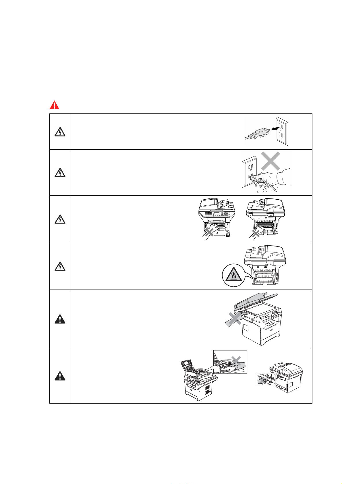
WARNING
There are high voltage electrodes inside the machine.
Before you clean the inside of the machine, make sure
you have unplugged the telephone line cord first and
then the power cord from the AC power outlet.
Do not handle the plug with wet hands.
Doing this might cause an electrical shock.
After you use the machine, some
internal parts are extremely HOT!
To prevent injuries, be careful not to
put your fingers in the areas shown
in the illustration.
The fuser unit is marked with a caution label.
Please do not remove or damage the label.
To prevent injuries, be careful not to put your
hands on the edge of the machine under the
scanner cover.
To prevent injuries, be careful not to
put your fingers in the area shown in
the illustrations.
Do not use a vacuum cleaner to clean up scattered toner. Doing this might cause the toner dust to
ignite inside the vacuum cleaner, potentially starting a fire. Please carefully clean the toner dust with
a dry, lint-free cloth and dispose of it according to local regulations.
Confidential
xii
Page 15
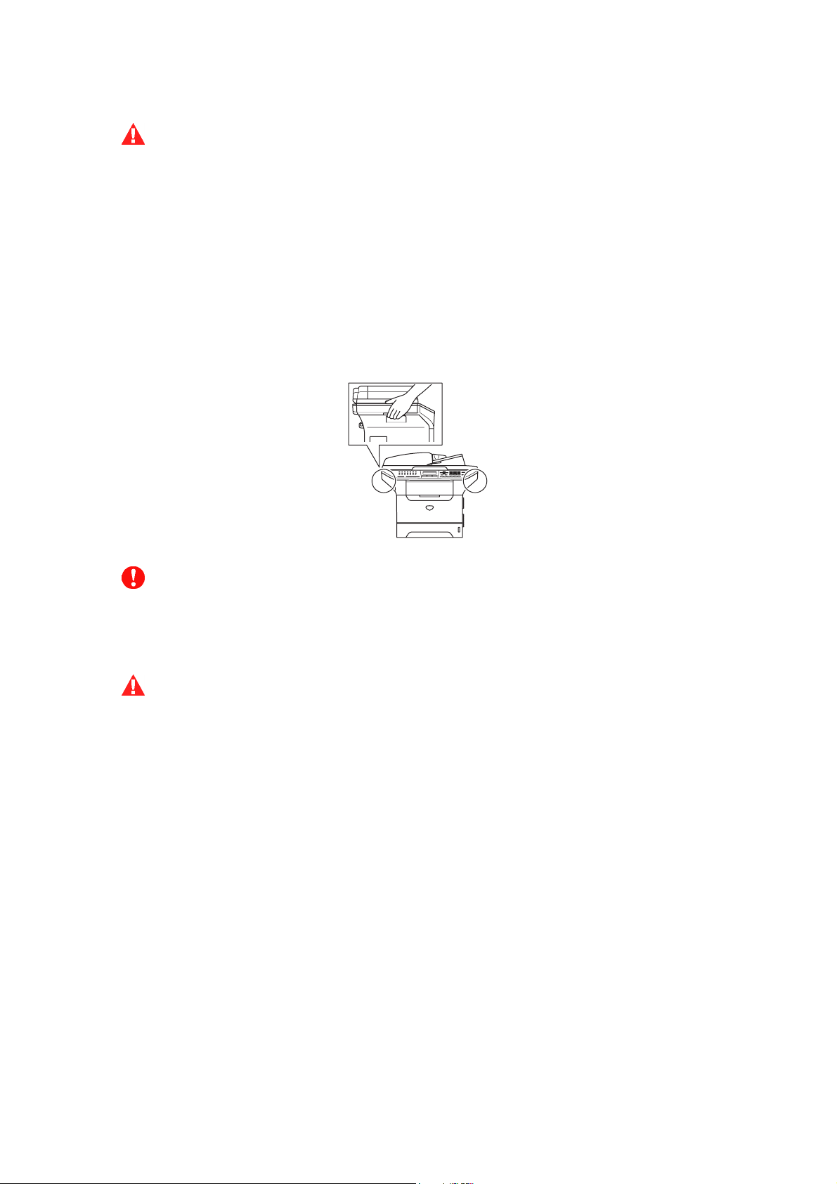
WARNING
- When you move the machine, grasp the side hand holds that are under the scanner. DO NOT
carry the machine by holding it at the bottom.
- Use caution when installing or modifying telephone lines.
Never touch telephone wires or
jack. Never install telephone wiring during a lightning storm. Never install a telephone wall
jack in a wet location.
- This product must be installed near an AC power outlet that is easily accessible.
In case of
an emergency, you must disconnect the power cord from the AC power outlet to shut off the
power completely.
- To reduce the risk of shock or fire, use only a No. 26 AWG or larger telecommunication line
cord.
CAUTION
Lightning and power surges can damage this product! We recommend that you use a quality
surge protection device on the AC power line and on the telephone line, or unplug the cords
during a lightning storm.
WARNING
IMPORTANT SAFETY INSTRUCTIONS
When using your telephone equipment, basic safety precautions should always be followed to
reduce the risk of fire, electric shock and injury to people, including the following:
1. Do not use this product near water, for example, near a bath tub, wash bowl, kitchen sink or
washing machine, in a wet basement or near a swimming pool.
2. Avoid using this product during an electrical storm. There may be a remote risk of electric
shock from lightning.
3. Do not use this product to report a gas leak in the vicinity of the leak.
4. Use only the power cord provided with the MACHINE.
SAVE THESE INSTRUCTIONS
Confidential
xiii
Page 16
CHOOSING A LOCATION
Place your machine on a flat, stable surface that is free of vibration and shocks, such as a desk.
Put the machine near a telephone wall jack and a standard, grounded AC power outlet.
Choose a location where the temperature remains between 50°F and 90.5°F (10°C and 32.5°C).
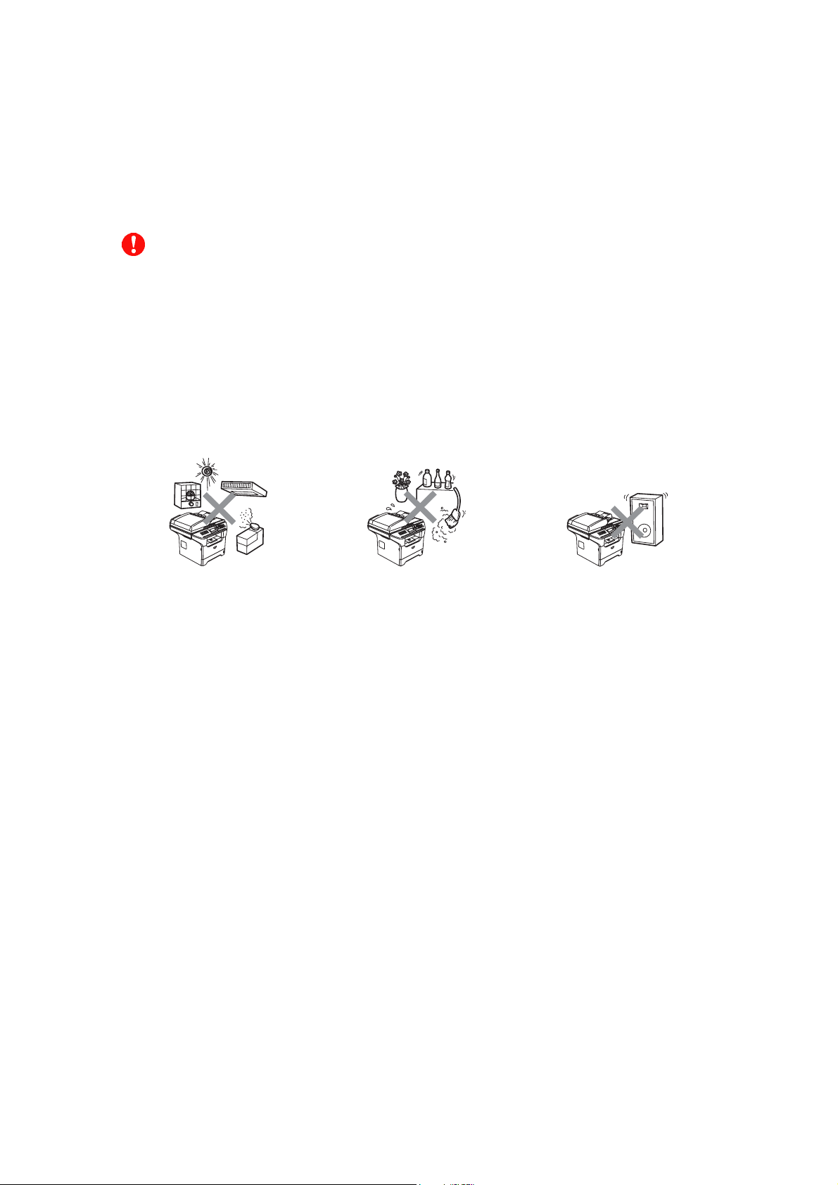
CAUTION
- Avoid placing your machine in a high-traffic area.
- Do not place the machine near heaters, air conditioners, water, chemicals, or refrigerators.
- Do not expose the machine to direct sunlight, excessive heat, moisture, or dust.
- Do not connect your
timers.
- Disruption of power can wipe out information in the
- Do not connect your machine to an AC power outlet on the same circuit as large appliances or
other equipment that might disrupt the power supply.
- Avoid interference sources, such as speakers or the base units of cordless phones.
machine to an AC power outlet controlled by wall switches or automatic
machine’s memory.
Confidential
xiv
Page 17

CHAPTER
PARTS NAMES & FUNCTIONS
1
Confidential
Page 18

CHAPTER 1 PARTS NAMES & FUNCTIONS
This chapter contains external views and names of components and describes their functions.
Information about the keys on the control panel is included to help you check operation or make
adjustments.
CONTENTS
1.1 EQUIPMENT OUTLINE ...................................................................................................1-1
1.2 CONTROL PANEL...........................................................................................................1-2
1.3 COMPONENTS................................................................................................................ 1-7
Confidential
Page 19
1.1 EQUIPMENT OUTLINE
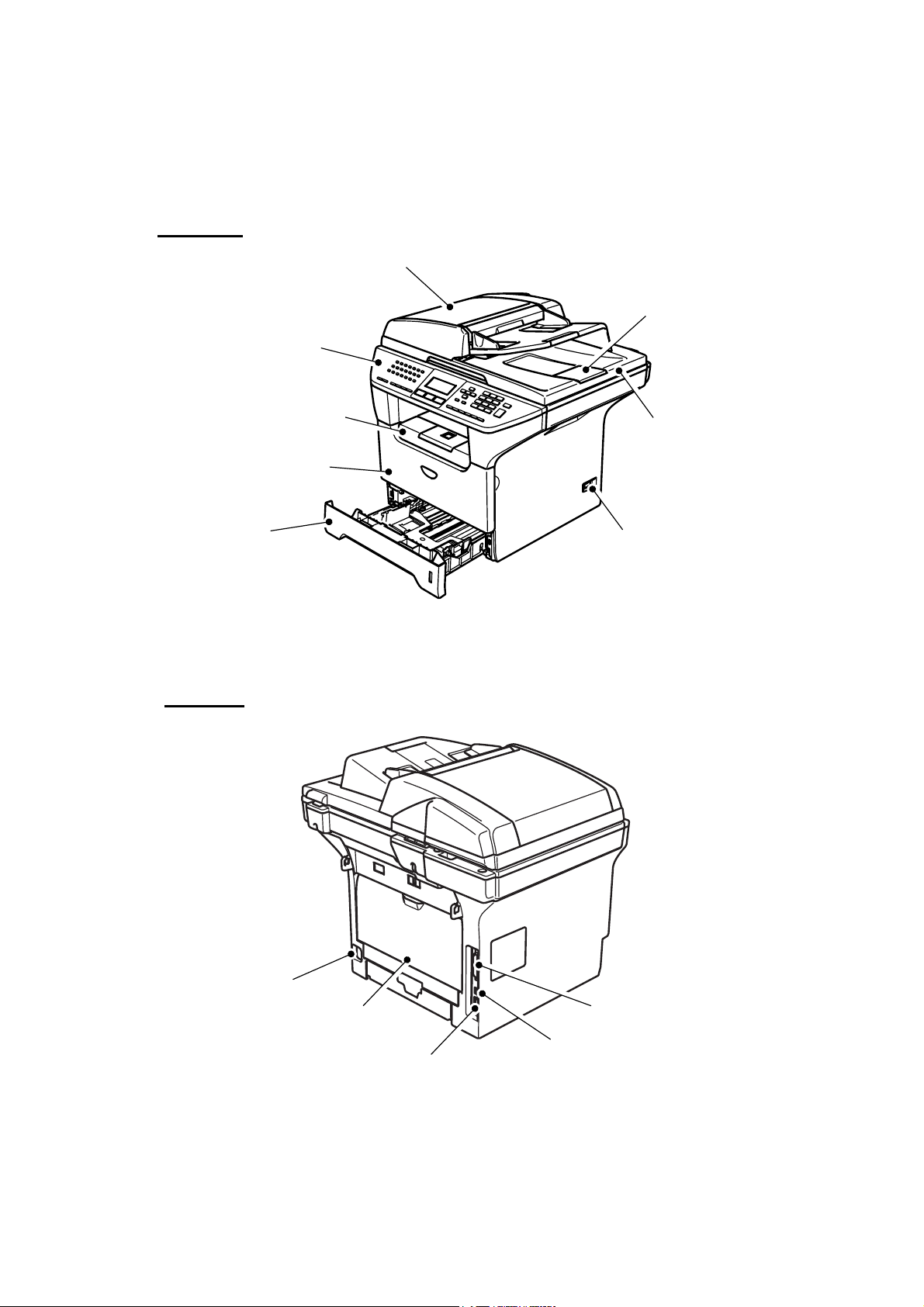
Front view
Automatic Document Feeder (ADF)
Control Panel
Face-down Output Tray
Support Flap with Extension
(Support Flap)
Front Cover
ADF Document Output Support Flap
Document Cover
Paper Tray
Rear view
Power Switch
Fig. 1-1
AC Power Connector
Back Cover
10/100 Baser TX Port
Parallel Interface Connector
USB Interface Connector
Fig. 1-2
1-1 Confidential
Page 20
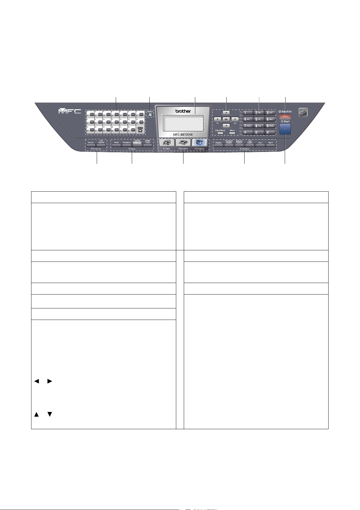
1.2 CONTROL PANEL
MFC-8460N, MFC-8860DN and MFC-8870DW have similar control keys.
3 4 5 6 2 1
1. One-Touch Keys
These 20 keys give you instant access to 40
previously stored numbers.
Shift
Lets you access One-Touch numbers 21 to 40 when
held down.
2. Status LED
The LED will flash and change color depending on
the machine status.
3. LCD 7. Start Key
Displays messages to help you use your machine.
4. Menu Keys
Menu
Accesses the main menu.
8 9 10 11
Fig. 1-3
Used to enter telephone and fax numbers or to
enter text.
The [#] key temporarily switches the dialing mode
from Pulse to Tone during a telephone call.
Stops an operation or exits from a menu.
Starts sending a fax, making a copy or scanning.
5. Dial pad Keys
6. Stop/Exit Key
7
Clear/Back
Deletes entered data or lets you exit the menu.
OK
Selects a setting.
or
Scrolls backwards or forwards through menu
selections.
Changes the volume when in fax or standby mode.
or
Scrolls through the menus and options.
1-2 Confidential
Page 21
8. Copy Keys
Duplex (For MFC-8860DN and MFC-8870DW)
You can choose Duplex to copy on both sides of
the paper.
Contrast/Quality
(For MFC-8860DN and MFC-8870DW)
Lets you change the quality or contrast for the next
copy.
Contrast (For MFC-8460N)
Lets you change the contrast for the next copy.
Quality (For MFC-8460N)
Lets you change the quality for the next copy.
Enlarge/Reduce
Reduces or enlarges copies.
Tray Select
Lets you change which tray will be used for the
next copy.
Sort
Sorts multiple copies using the ADF.
N in 1
You can choose N in 1 to copy 2 or 4 pages onto
one page.
Hook
10. Fax and Telephone Keys
Press before dialing if you want to make sure a fax
machine answers, and then press [Start] key.
Also, press this key after you pick up the handset
of an external telephone during the F/T ring (fast
double-rings).
Resolution
Sets the resolution when sending a fax.
Search/Speed Dial
Lets you look up numbers stored in the dialing
memory and LDAP server* (* MFC-8860DN and
MFC-8870DW).
You can search the stored number by
alphabetically.
It also lets you look up the stored number in SpeedDial numbers by pressing [Shift] key and [Speed-
Dial] key simultaneously and then the three digit
number.
Redial/Pause
Redials the last number called. It also inserts a
pause when programming quick dial numbers.
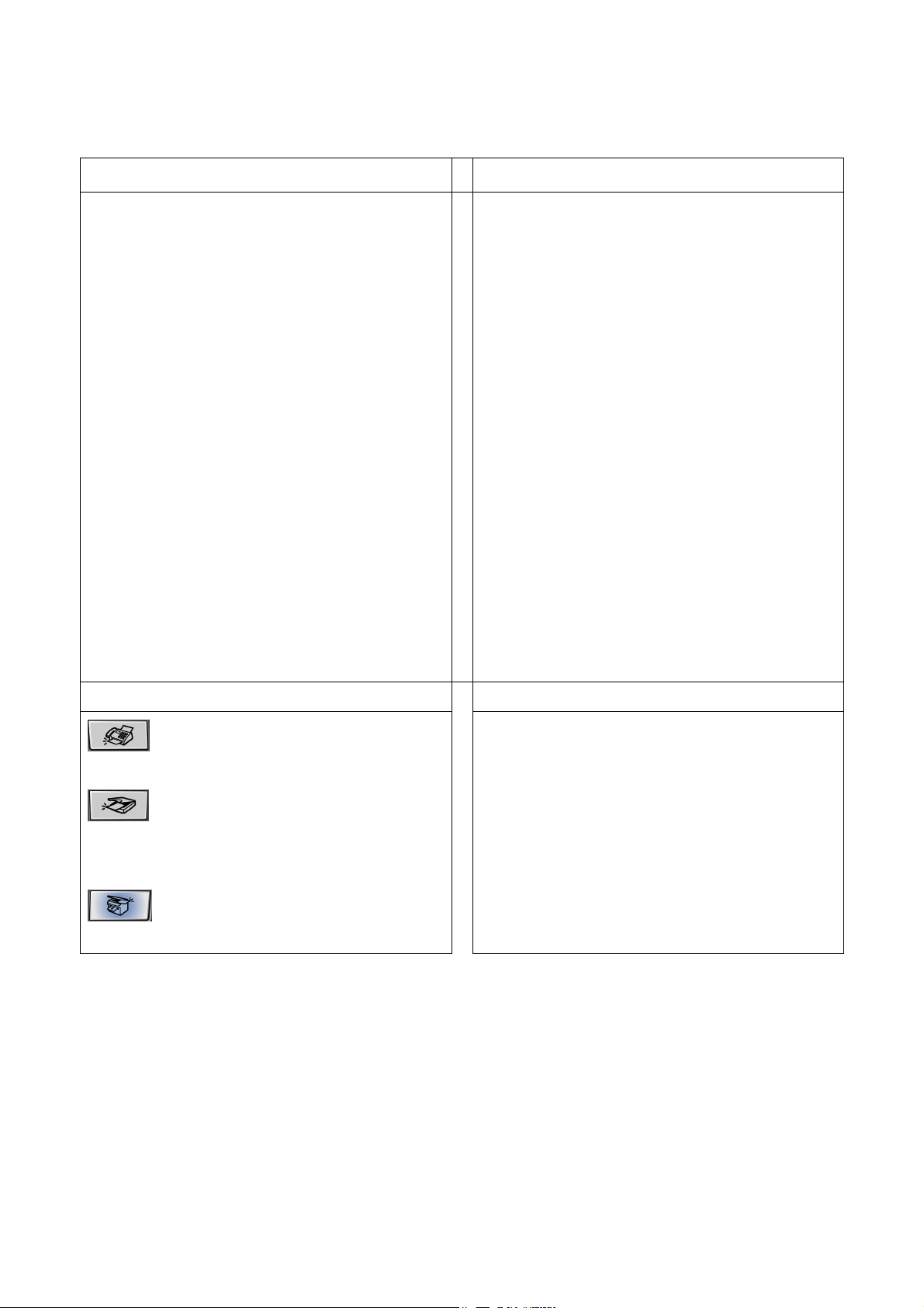
9. Mode Keys
Fax
Puts the machine in Fax mode.
Scan
Puts the machine in Scan mode.
(For details about scanning. See Software User’s
Guide on the CD-ROM.)
Copy
Puts the machine in Copy mode.
Secure
11. Print Keys
Prints data saved in memory when you enter your
four-digit password.
Job Cancel
Cancels a print job and clears the machine memory.
1-3 Confidential
Page 22
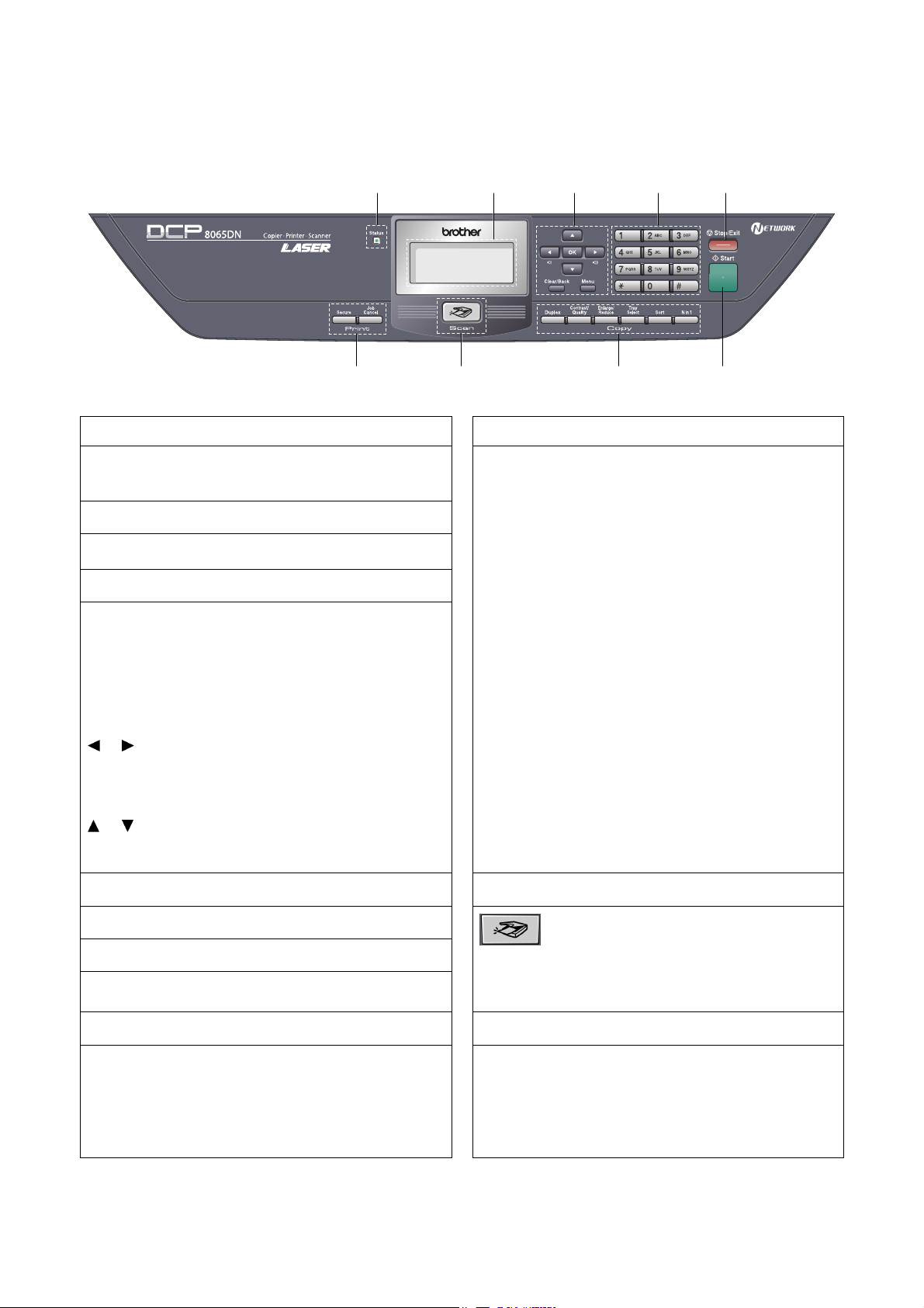
DCP-8060 and DCP-8065DN have similar control keys.
2 3 4 5 1
9
1. Status LED
The LED will flash and change color depending on
the machine status.
2. LCD
Displays messages to help you use your machine.
3. Menu Keys
Menu
Accesses the main menu.
Clear/Back
Deletes entered data or lets you exit the menu.
OK
Selects a setting.
or
Scrolls backwards or forwards through menu
selections.
Changes the volume when in standby mode.
or
Scrolls through the menus and options.
4. Dial pad
6
Fig. 1-4
Duplex (For DCP-8065DN)
7 8
7. Copy Keys
You can choose Duplex to copy on both sides of
the paper.
Contrast/Quality (For DCP-8065DN)
Lets you change the quality or contrast for the next
copy.
Contrast (For DCP-8060)
Lets you change the contrast for the next copy.
Quality (For DCP-8060)
Lets you change the quality for the next copy.
Enlarge/Reduce
Reduces or enlarges copies.
Tray Select
Lets you change which tray will be used for the
next copy.
Sort
Sorts multiple copies using the ADF.
N in 1
You can choose N in 1 to copy 2 or 4 pages onto
one page.
8. Scan Key
Used to enter text.
5. Stop/Exit Key
Stops an operation or exits from a menu.
6. Start Key
Starts making a copy or scanning.
Puts the machine in Scan mode.
(For details about scanning. See Software User’s
Scan
Guide on the CD-ROM.)
Secure
9. Print Keys
Prints data saved in memory when you enter your
four-digit password.
Job Cancel
Cancels a print job and clears the machine memory.
1-4 Confidential
Page 23
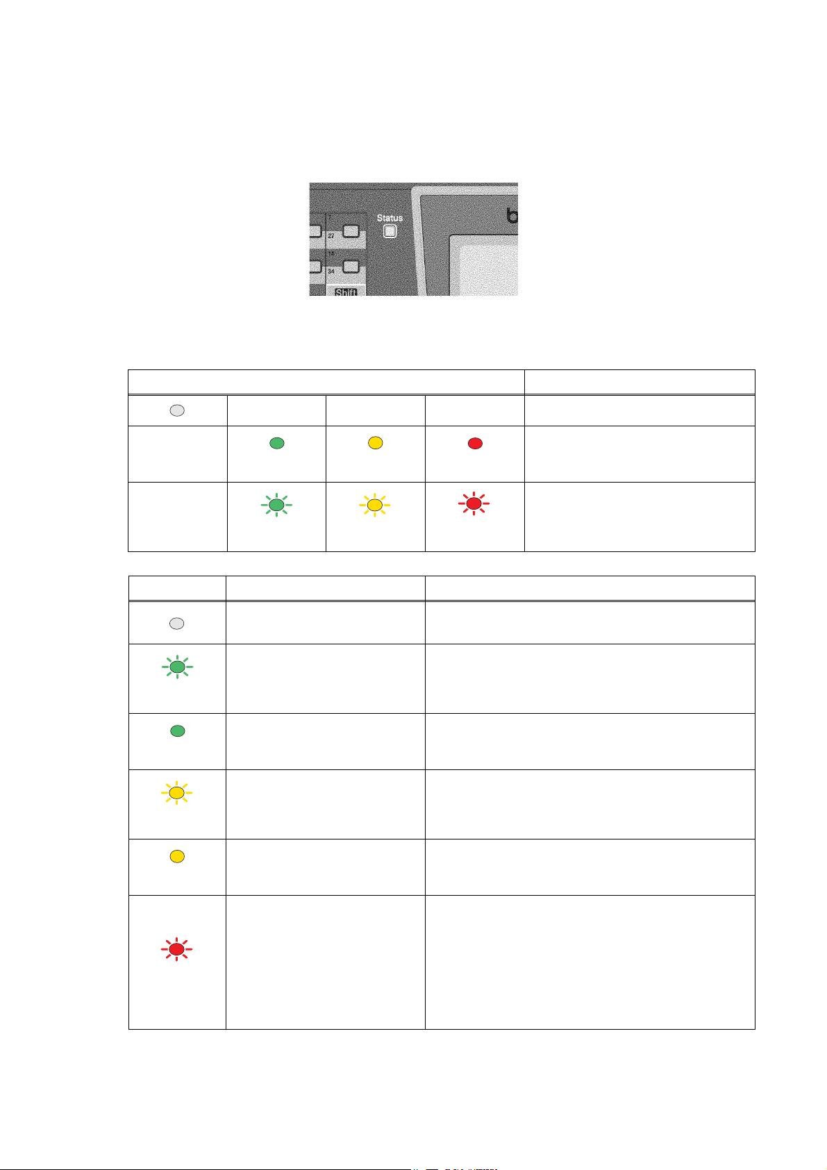
< Status LED indications >
The Status LED (Light Emitting Diode) will flash and change color depending on the machine status.
Fig. 1-5
The LED indications shown in the table below are used in the illustrations in this chapter.
LED LED Status
LED is off.
Green
Yellow
Red
LED is on.
LED is blinking.
Green
Yellow
Red
LED Machine Status Description
Sleep Mode The power switch is off or the machine is in Sleep
mode.
Warming Up The machine is warming up for printing.
Green
Ready The machine is ready to print.
Green
Receiving Data The machine is either receiving data from the
Yellow
computer, processing data in memory or printing
data.
Data Remaining in Memory Print data remains in the machine memory.
Yellow
Service error Follow the steps below.
1. Turn off the power switch.
2. Wait a few seconds, and then turn it back on and
Red
try to print again.
If you cannot clear the error and see the same
service call indication after turning the machine
back on, please call Brother Customer Service.
1-5 Confidential
Page 24

LED Machine Status Description
Cover open The front cover or the back cover is open.
Close the cover.
Toner Life End Replace the toner cartridge with a new one.
Red
Paper error Put paper in the tray or clear the paper jam.
Check the LCD message.
Scan lock Check that the scanner lock lever is released.
Others Check the LCD message.
Out of memory Memory is full.
NOTE: When the power switch is off or the machine is in Sleep mode, the LED is off.
1-6 Confidential
Page 25
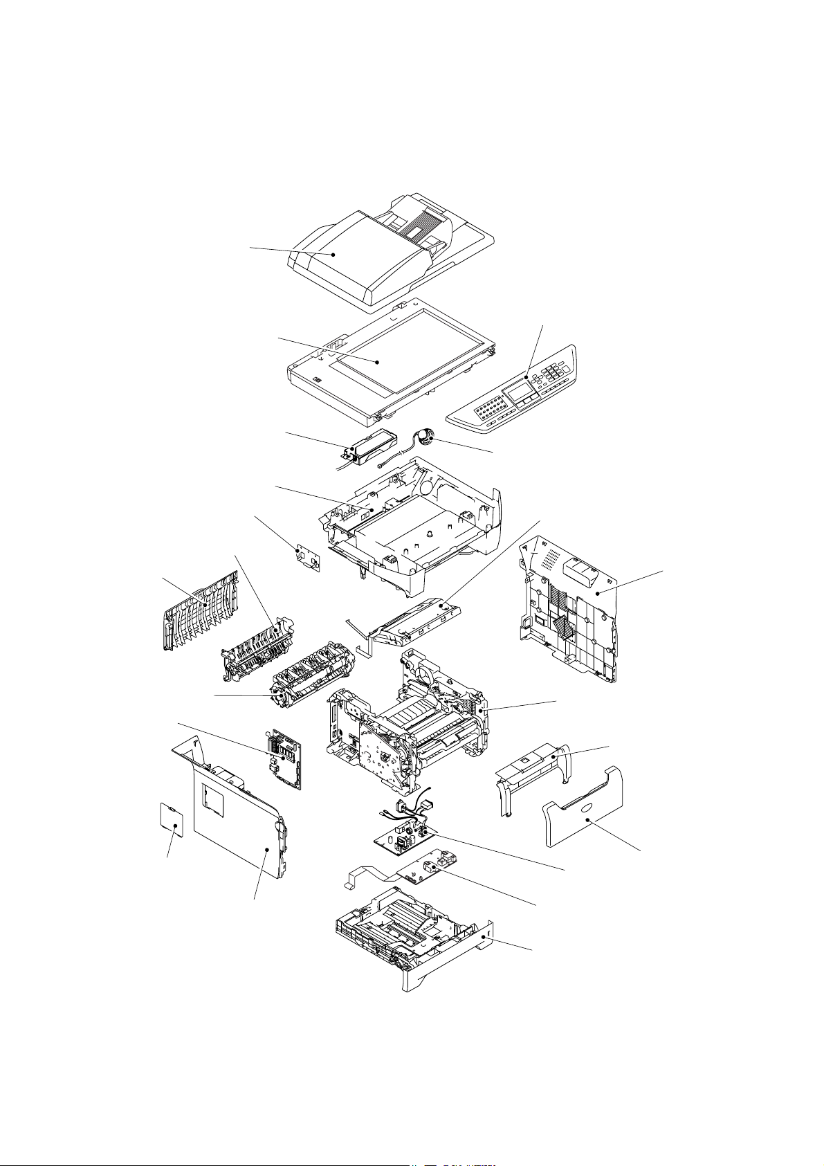
1.3 COMPONENTS
N
The equipment consists of the following major components:
ADF Unit
Scanner Unit
CU PCB
Joint Cover ASSY
Driver PCB
Outer Chute ASSY
Panel Unit
Speaker ASSY
Laser Unit
Back Cover
Fuser Unit
Main PCB
Access Cover
Side Cover L
Side Cover R
Frame Unit
Process Cover ASSY
Front Cover
PS PCB
High-voltage PS PCB
Paper Tray
Fig. 1-6
1-7 Confidential
Page 26

CHAPTER
SPECIFICATIONS
2
Confidential
Page 27

CHAPTER 2 SPECIFICATIONS
This chapter lists the specifications of each model, which enables you to make a comparison of
different models.
CONTENTS
2.1 GENERAL ........................................................................................................................2-1
2.1.1 General Specifications ......................................................................................... 2-1
2.1.2 Paper Specifications............................................................................................. 2-2
2.1.2.1 Paper handling ...............................................................................................2-2
2.1.2.2 Media specifications ....................................................................................... 2-2
2.1.3 Printable Area ................................................................................................................ 2-5
2.1.3.1 PCL5e/EPSON/IBM emulation .......................................................................2-5
2.1.3.2 PCLXL, PS (BR-Script 3)................................................................................2-8
2.1.4 Print Speeds with Various Settings .............................................................................2-9
2.1.5 Toner Cartridge Weight Information .........................................................................2-10
2.2 SPECIFICATIONS LIST.................................................................................................2-11
Confidential
Page 28

2.1 GENERAL
2.1.1 General Specifications
Memory Capacity 32 MB
Automatic Document Feeder (ADF) Up to 50 sheets (Staggered)
Paper Tray 250 Sheets (20 lb (80 g/m 2 ))
Printer Type Laser
Print Method Electrophotography by semiconductor laser beam
Liquid Crystal Display (LCD) 22 characters x 5 lines
Power Source 120V AC 50/60Hz (U.S.A./Canada)
Power Consumption Sleep: 17W (Average) (For the models with the NCU)
Dimensions (W x D x H) 531 mm x 450 mm x 475 mm (20.9” x 17.7” x 18.7”)
scanning
220 to 240V AC 50/60Hz (Europe/Asia/Oceania)
: 15W (Average) (For the models with out NCU)
Standby: 85W (Average)
Peak: 1092W (U.S.A./Canada)
1104W (Europe/Asia/Oceania)
(with out carton)
Weight Without Drum/Toner Unit:
MFC-8460N: 16.5 kg (36.4 lb)
MFC-8860DN/8870DW: 16.7 kg (36.81 lb)
Noise Operating: 55 dB A or less (when ADF scanning)
Standby: 30 dB A or less
Temperature Operating: 10 to 32.5°C (50°F to 90.5°F)
Storage: 0 to 40°C (32°F to 104°F)
Humidity Operating: 20 to 80% (without condensation)
Storage: 10 to 90% (without condensation)
2-1 Confidential
Page 29

2.1.2 Paper Specifications
2.1.2.1 Paper handling
Paper Input* All models
Multi-purpose tray 50 sheets
Paper tray (Standard) 250 sheets
Lower tray (Option) 250 sheets
* Calculated with 80 g/m2 (21 lb) paper.
Paper Input* All models
Face-down 150 sheets
* Calculated with 80 g/m2 (21 lb) paper.
Duplex MFC-8460N/DCP8060
Manual Duplex Yes
Automatic Duplex N/A Yes
2.1.2.2 Media specifications
(1) Media types
The machine loads paper from the installed paper tray or the multi-purpose tray. The feedable
media type and size are different depending on the paper tray installed. The names for the
paper trays in the printer driver and this guides are as follows;
Paper tray Tray 1
Multi-purpose tray MP Tray
Optional lower tray unit Tray 2
Duplex tray for automatic duplex printing
(for MFC-8860DN/8870DW, DCP-8065DN)
The table in the next page shows the feedable media of each paper tray described above.
MFC-8860DN/8870DW
DCP-8065DN
DX
2-2 Confidential
Page 30
Choose the media
Tray 1/2 MP Tray DX
type from the
printer driver
Plain paper
75 g/m
2
to 105 g/m
2
Yes Yes
Yes Plain paper
(20 to 28 lbs.)
Recycled paper Yes Yes Yes Recycled paper
Bond paper
Rough paper60 g/m
2
to 161 g/m
(16 to 43 lbs.)
60 g/m
2
Yes
2
to 105 g/m2
(16 to 28 lbs.)
Yes
2
60 g/m
to 161 g/m2
(16 to 43 lbs.)
N/A Bond paper
Thin paper
60 g/m
2
to 75 g/m
2
Yes Yes
Yes Thin paper
(16 to 20 lbs.)
Thick paper
105 g/m
2
to 161 g/m
2
N/A Yes
(28 to 43 lbs.)
Yes
Transparency
Up to 10 sheets
A4 or Letter **
Labels N/A
Yes
Up to 10 sheets
A4 or Letter
Yes
A4 or Letter
N/A
N/A Transparencies
N/A Thicker Paper
Thick Paper or
Thicker Paper
Envelopes,
Envelopes N/A Yes N/A
Env. Thin,
Env. Thick
* Up to 10 sheets
** Not available for the optional Tray 2.
(2) Media size
Tray 1 (Standard) Tray 2 (Option)
A4, Letter, Legal*,
B5 (ISO), Excutive,
A5, A6, B6 (ISO)
A4, Letter, Legal*,
B5 (ISO), Excutive,
A5, B6 (ISO)
* Legal size paper is not available in some regions outside the U.S.A. and Canada.
(3) Media weights
Tray 1
Lower tray unit
(Option) (LT-5300)
60 to 105 g/m2
(16 to 28 lb.)
60 to 105 g/m2
(16 to 28 lb.)
Tray 2
MP Tray DX
Width:
69.9 to 215.9 mm
(2.75 to 8.5 in.)
Length:
116 to 406.4 mm
(4.57 to 16 in.)
MP Tray DX
60 to 161 g/m2
(16 to 43 lb.)
A4, Letter, Legal*
60 to 105 g/m2
(16 to 28 lb.)
2-3 Confidential
Page 31

(4) Recommended paper
Europe U.S.A.
Plain paper Xerox Premier 80 g/m
Xerox Business 80 g/m
2
2
Xerox 4200DP 20lb
Hammermill Laser Paper 24lb
M-real DATACOPY 80 g/m2
Recycled paper Xerox Recycled Supreme N/A
Transparency 3M CG3300 3M CG 3300
Label Avery laser label L7163 Avery laser label #5160
* This machine can use recycled paper that meets the DIN 19309 specification.
(5) Moisture content
Moisture content: 4% to 6% by weight
CAUTION
When you are choosing print media, be sure to follow the information given below to prevent
any paper jams, print quality problems or machine damage;
- It is recommended to use long-grained paper for the best print quality. If short-grained
paper is being used, it might be the cause of paper jams.
- Use neutral paper. Do not use acid paper to avoid any damage to the drum unit.
- Avoid using coated paper such as vinyl coated paper.
- Avoid using preprinted or highly textured paper.
- It is recommended to use labels or transparencies which are designed for use in laser
machines.
- Avoid feeding labels with the carrier sheet exposed, or the machine will be damaged.
- Before loading paper with holes such as organizer sheets, be sure to fan the stack well.
- Do not use organizer sheets that are stuck together. The glue that is used might caused
damaged to the machine.
- When printing on the back of pre-printed paper, if the paper is curled, be sure to straighten
the paper as much as possible.
Different types of paper should not be loaded at the same time in the paper tray to avoid any
paper jams or misfeeds.
2-4 Confidential
Page 32

2.1.3 Printable Area
2.1.3.1 PCL5e/EPSON/IBM emulation
When using PCL emulation, the edges of the paper that cannot be printed on are shown below.
Portrait
G
E
G
G
C
A
F
E
B
D
G
F
B Physical page length
D
F
NOTE:
- “Logical page” shows the printable area for a PCL driver.
Physical page
Printable area
Logical page
Maximum logical page length
Distance from edge of physical page to
edge of logical page
- “Printable area” shows mechanical printable area of the machine.
- Therefore, the machine can only print within the shaded area when you use a PCL driver.
2-5 Confidential
Page 33

The table below shows the printable areas when printing on Portrait for each paper size.
Size A B C D E F G
Letter
Legal
Folio
Executive
A4
A5
A6
B5 (JIS)
B5 (ISO)
B6 (ISO)
COM10
MONARCH
C5
DL
DLL
215.9 mm
8.5”
(2,550 dots)
215.9 mm
8.5”
(2,550 dots)
215.9 mm
8.5”
(2,550 dots)
184.15 mm
7.25”
(2,175 dots)
210.0 mm
8.27”
(2,480 dots)
148.5 mm
5.85”
(1,754 dots)
105.0 mm
4.13”
(1,240 dots)
182.0 mm
7.1”
(2,130 dots)
176.0 mm
6.93”
(2,078 dots)
125.0 mm
4.92”
(1,476 dots)
104.78 mm
4.125”
(1,237 dots)
98.43 mm
3.875”
(1,162 dots)
162.0 mm
6.38”
(1,913 dots)
110.0 mm
4.33”
(1,299 dots)
220.0 mm
8.66”
(2,598 dots)
279.4 mm
11.0”
(3,300 dots)
355.6 mm
14.0”
(4,200 dots)
330.2mm
13.0”
(3,900 dots)
266.7 mm
10.5”
(3,150 dots)
297.0 mm
11.69”
(3,507 dots)
210.0 mm
8.27”
(2,480 dots)
148.5 mm
5.85”
(1,754 dots)
257.0 mm
10.11”
(3,033 dots)
250.0 mm
9.84”
(2,952 dots)
176.0 mm
6.93”
(2,078 dots)
241.3 mm
9.5”
(2,850 dots)
190.5 mm
7.5”
(2,250 dots)
229.0 mm
9.01”
(2,704 dots)
220.0 mm
8.66”
(2,598 dots)
110.0 mm
4.33”
(1,299 dots)
203.2 mm
8.0”
(2,400 dots)
203.2 mm
8.0”
(2,400 dots)
203.2 mm
8.0”
(2,400 dots)
175.7 mm
6.92”
(2,025 dots)
198.0 mm
7.79”
(2,338 dots)
136.5 mm
5.37”
(1,612 dots)
93.0 mm
3.66”
(1,098 dots)
170.0 mm
6.69”
(2,007 dots)
164.0 mm
6.46”
(1,936 dots)
164.0 mm
4.44”
(1,334 dots)
92.11 mm
3.63”
(1,087 dots)
85.7 mm
3.37”
(1,012 dots)
150.0 mm
5.9”
(1,771 dots)
98.0 mm
3.86”
(1,157 dots)
207.4 mm
8.17”
(2,450 dots)
279.4 mm
11.0”
(3,300 dots)
355.6 mm
14.0”
(4,200 dots)
330.2mm
13.0”
(3,900 dots)
266.7 mm
10.5”
(3,150 dots)
297.0 mm
11.69”
(3,507 dots)
210.0 mm
8.27”
(2,480 dots)
148.5 mm
5.85”
(1,754 dots)
257.0 mm
10.11”
(3,033 dots)
250.0 mm
9.84”
(2,952 dots)
176.0 mm
6.93”
(2,078 dots)
241.3 mm
9.5”
(2,850 dots)
190.5 mm
7.5”
(2,250 dots)
229.0 mm
9.01”
(2,704 dots)
220.0 mm
8.66”
(2,598 dots)
110.0 mm
4.33”
(1,299 dots)
6.35 mm
0.25”
(75 dots)
6.35 mm
0.25”
(75 dots)
6.35 mm
0.25”
(75 dots)
6.35 mm
0.25”
(75 dots)
6.01 mm
0.24”
(71 dots)
6.01 mm
0.24”
(71 dots)
6.01 mm
0.24”
(71 dots)
6.01 mm
0.24”
(71 dots)
6.01 mm
0.24”
(71 dots)
6.01 mm
0.24”
(71 dots)
6.35 mm
0.25”
(75 dots)
6.35 mm
0.25”
(75 dots)
6.01 mm
0.24”
(71 dots)
6.01 mm
0.24”
(71 dots)
6.27 mm
0.25”
(74 dots)
0 mm
0 mm
0 mm
0 mm
0 mm
0 mm
0 mm
0 mm
0 mm
0 mm
0 mm
0 mm
0 mm
0 mm
0 mm
NOTE:
- The paper sizes indicated here should confirm to the nominal dimensions specified by JIS
except B5 (ISO), B6 (ISO).
4.2 mm
0.16”
(50 dots)
4.2 mm
0.16”
(50 dots)
4.2 mm
0.16”
(50 dots)
4.2 mm
0.16”
(50 dots)
4.2 mm
0.16”
(50 dots)
4.2 mm
0.16”
(50 dots)
4.2 mm
0.16”
(50 dots)
4.2 mm
0.16”
(50 dots)
4.2 mm
0.16”
(50 dots)
4.2 mm
0.16”
(50 dots)
4.2 mm
0.16”
(50 dots)
4.2 mm
0.16”
(50 dots)
4.2 mm
0.16”
(50 dots)
4.2 mm
0.16”
(50 dots)
6.27 mm
0.25”
(74 dots)
- The dot size is based on 300 dpi resolution.
2-6 Confidential
Page 34

Landscape
G
E
G
G
C
A
F
E
D
B
G
F
NOTE:
- “Logical page” shows the printable area for a PCL driver.
Physical page
Printable area
Logical page
B Physical page length
D Maximum logical page length
F Distance from edge of physical
page to edge of logical page
- “Printable area” shows mechanical printable area of the machine.
- Therefore, the machine can only print within the shaded area when you use a PCL driver.
2-7 Confidential
Page 35

The table below shows the printable areas when printing on Landscape for each paper size.
Size A B C D E F G
Letter
Legal
Folio
Executive
A4
A5
A6
B5 (JIS)
B5 (ISO)
B6 (ISO)
COM10
MONARCH
C5
DL
DLL
279.4 mm
11.0”
(3,300 dots)
355.6 mm
14.0”
(4,200 dots)
330.2mm
13.0”
(3,900 dots)
266.7 mm
10.5”
(3,150 dots)
297.0 mm
11.69”
(3,507 dots)
210.0 mm
8.27”
(2,480 dots)
148.5 mm
5.85”
(1,754 dots)
257.0 mm
10.11”
(3,033 dots)
250.0 mm
9.84”
(2,952 dots)
176.0 mm
6.93”
(2,078 dots)
241.3 mm
9.5”
(2,850 dots)
190.5 mm
7.5”
(2,250 dots)
229.0 mm
9.01”
(2,704 dots)
220.0 mm
8.66”
(2,598 dots)
110.0 mm
4.33”
(1,299 dots)
215.9 mm
8.5”
(2,550 dots)
215.9 mm
8.5”
(2,550 dots)
215.9 mm
8.5”
(2,550 dots)
184.15 mm
7.25”
(2,175 dots)
210.0 mm
8.27”
(2,480 dots)
148.5 mm
5.85”
(1,754 dots)
105.0 mm
4.13”
(1,240 dots)
182.0 mm
7.1”
(2,130 dots)
176.0 mm
6.93”
(2,078 dots)
125.0 mm
4.92”
(1,476 dots)
104.78 mm
4.125”
(1,237 dots)
98.43 mm
3.875”
(1,162 dots)
162.0 mm
6.38”
(1,913 dots)
110.0 mm
4.33”
(1,299 dots)
220.0 mm
8.66”
(2,598 dots)
269.3 mm
10.6”
(3,180 dots)
345.5 mm
13.6”
(4,080 dots)
320.0 mm
12.6”
(3,780 dots)
256.6 mm
10.1”
(3,030 dots)
287.0 mm
11.2”
(3,389 dots)
200.0 mm
7.87”
(2,362 dots)
138.5 mm
5.45”
(1,636 dots)
247.0 mm
9.72”
(2,916 dots)
240.0 mm
9.44”
(2,834 dots)
166.4 mm
6.55”
(1,960 dots)
231.1 mm
9.1”
(2,730 dots)
180.4 mm
7.1”
(2,130 dots)
219.0 mm
8.62”
(2,586 dots)
210.0 mm
8.26”
(2,480 dots)
97.5 mm
3.84”
(1,151 dots)
215.9 mm
8.5”
(2,550 dots)
215.9 mm
8.5”
(2,550 dots)
215.9 mm
8.5”
(2,550 dots)
184.15 mm
7.25”
(2,175 dots)
210.0 mm
8.27”
(2,480 dots)
148.5 mm
5.85”
(1,754 dots)
105.0 mm
4.13”
(1,240 dots)
182.0 mm
7.1”
(2,130 dots)
176.0 mm
6.93”
(2,078 dots)
125.0 mm
4.92”
(1,476 dots)
104.78 mm
4.125”
(1,237 dots)
98.43 mm
3.875”
(1,162 dots)
162.0 mm
6.38”
(1,913 dots)
110.0 mm
4.33”
(1,299 dots)
220.0 mm
8.66”
(2,598 dots)
5.0 mm
0.2”
(60 dots)
5.0 mm
0.2”
(60 dots)
5.0 mm
0.2”
(60 dots)
5.0 mm
0.2”
(60 dots)
4.8 mm
0.19”
(59 dots)
4.8 mm
0.19”
(59 dots)
4.8 mm
0.19”
(59 dots)
4.8 mm
0.19”
(59 dots)
4.8 mm
0.19”
(59 dots)
4.8 mm
0.19”
(59 dots)
5.0 mm
0.2”
(60 dots)
5.0 mm
0.2”
(60 dots)
4.8 mm
0.19”
(59 dots)
4.8 mm
0.19”
(59 dots)
6.27 mm
0.25”
(74 dots)
0 mm
0 mm
0 mm
0 mm
0 mm
0 mm
0 mm
0 mm
0 mm
0 mm
0 mm
0 mm
0 mm
0 mm
0 mm
NOTE:
- The paper sizes indicated here should confirm to the nominal dimensions specified by JIS
except B5 (ISO), B6 (ISO).
4.2 mm
0.16”
(50 dots)
4.2 mm
0.16”
(50 dots)
4.2 mm
0.16”
(50 dots)
4.2 mm
0.16”
(50 dots)
4.2 mm
0.16”
(50 dots)
4.2 mm
0.16”
(50 dots)
4.2 mm
0.16”
(50 dots)
4.2 mm
0.16”
(50 dots)
4.2 mm
0.16”
(50 dots)
4.2 mm
0.16”
(50 dots)
4.2 mm
0.16”
(50 dots)
4.2 mm
0.16”
(50 dots)
4.2 mm
0.16”
(50 dots)
4.2 mm
0.16”
(50 dots)
6.27 mm
0.25”
(74 dots)
- The dot size is based on 300 dpi resolution.
2.1.3.2 PCLXL, PS (BR-Script 3)
You can not print within 4.2 mm (50dots in 300 dpi mode) on all four sides of the paper.
2-8 Confidential
Page 36

2.1.4 Print Speeds with Various Settings
Print speed is up to 28 ppm for A4 size and 30 ppm for Letter size when loading A4 or Letter size
paper from the paper tray in the plain paper mode.
Actual print speed varies depending on the media type or paper size as shown in the tables below;
<A4/Letter size>
Media type setting All models
Transparency 28/30 ppm
Thin Paper 28/30 ppm
Plain Paper 28/30 ppm
Recycled Paper 28/30 ppm
Thick Paper, Envelopes, Env.Thin 14 ppm
Thicker/Bond Paper, Env.Thick 3 ppm
< Smaller size than A4 or Letter
Media type setting All models
Transparency 28/30 ppm
Thin Paper 28/30 ppm
Plain Paper 90 sec 28/30 ppm Æ 14 ppm
Recycled Paper 90 sec 28/30 ppm Æ 14 ppm
Env.Thin 14 ppm
Thick Paper, Envelopes 14 ppm
Thicker/Bond Paper, Env.Thick 3 ppm
NOTE:
- The print speed may vary according to conditions, such as paper size and paper tray.
- When a smaller size paper than A4 or Letter is printed, the temperature on both edges of the
fuser unit is much higher than the temperature on the center of the unit where the paper is fed
depending on the setting or model. Therefore, the print speed is slowed in order to decrease the
temperature on the edges after the specified time, it is maximum print speed when you first start
printing.
- The actual print speed varies depending on the paper size.
2-9 Confidential
Page 37

2.1.5 Toner Cartridge Weight Information
<Toner Cartridge Weight (approximate weight)>
TN580
(U.S.A./Canada)
Brand new Toner Cartridge Weight
Toner Weight at Brand New Toner Cartridge
Toner Cartridge Weight at Toner Near Empty
Remain Toner Weight at Toner Near Empty
Toner Cartridge Weight at Toner Life End
Remain Toner Weight at Toner Life End
TN550
(U.S.A./Canada)
TN-3170
(Europe)
727g
190g
617g (± 13g)
77g
605g (± 10g)
68g
TN-3130
(Europe)
TN-3185
(Asia/Oceania)
TN-3145
(Asia/Oceania)
Brand new Toner Cartridge Weight 663g
Toner Weight at Brand New Toner Cartridge 126g
Toner Cartridge Weight at Toner Near Empty 617g (± 13g)
Remain Toner Weight at Toner Near Empty 77g
Toner Cartridge Weight at Toner Life End 602g (± 10g)
Remain Toner Weight at Toner Life End 65g
NOTE:
- Without yellow protector, DR cover.
- Toner cartridge weight may vary within 2 to 3g depending on the cartridge weight.
- You can print about 630 pages
with 10g toner.
(A4 size, 5% coverage, continuous printing)
- The figure has varied quite a bit, for example from 590 pages to 720 pages, on a comparison of
printing test results.
2-10 Confidential
Page 38

2.2 SPECIFICATIONS LIST
p
y
y
,
,
(
MFC-8460N
(1/5)
Model Name
GENERAL
Print Engine
CPU Speed
Back up Clock
Operating Environment
On/Off Switch
Demo Print
Demo Model
Starter Toner
Simultaneous Operation
Supported OS Version
Paper Input Capacity
Paper Output Capacity
Input Media Size
Media Types MP Tray
Media Weights
LCD Size
LCD Dimention
LCD Back-Lit
Memory Capacity (Standard : MByte)
Memory BackUp
Optional Memory
Function Lock
Setting Lock
Dimensions w/ Carton (WxDxH)
Dimensions w/o Carton (WxDxH)
Weight w/ Carton
Weight w/o Carton
Color
Power Source
Power Consumption (Copying)
Power Consumption (Sleep/Standby/Peak)
Power Save ( CPU Sleep )
Temperature
Humidity
ADF
Pa
Optional Tra
Multi-Purpose Tray
ADF
MP Tray
Paper Tray (Standard)
Paper Tray (Option)
Paper Tray
Paper Tray (Option)
ADF
MP Tray
Paper Tray
W x L) *7
er Tra
US/Canada Europe Asia/Pacific
20% - 80% (without condensation)
Yes
Win/98(SE)/Me, WinNT4.0/2K/XP
MacOS 9.1 - 9.2/ OSX 10.2.4 or greater
(XX4024 or 4200 20lbs, environment: temp. 20-30C humiditiy 50-70%)
Yes (up to 50 sheets by 20lbs paper)
Width 148.0 to 215.9 mm, Length 148.0 to 355.6 mm
(Width 5.8" to 8.5", Length 5.8" to 14")
Width 69.9 to 215.9 mm, Length 116 to 406.4 mm
A4, Letter, B5 (ISO), A5,
A6, Exe, Legal, Folio
B6
A4, Letter, B5 (ISO), A5,
Exe, Legal, Folio
B6
Plain Paper, Bond Paper, Recycled Paper, Envelopes, Labels, and
1 DIMM (144pin) slot (64, 128, 256, 512MB) ; expandable up to 544MB
120V AC 50/60(Canada)Hz
Average 17W/85W/1092W
(Width 2.75" to 8.50", Length 4.57" to 16")
Plain Paper, Bond Paper, Recycled Paper, Transparencies
Plain Paper, Bond Paper, Recycled Paper
22 characters x 5 lines (Full Dot)
maximum message is 16 characters
Yes (up to 4 days for standard memory)
Front/TOP Cover : 1581Gray , Side cover/Panel : 1736Gray
AL-FB Base
MFC-8460N
Laser ( AL )
266MHz
Yes (up to 4 days)
10 - 32.5 degrees Centigrade
Yes
N/A
N/A
Standard Toner (3.5K)
Yes
up to 50 sheets
250 sheets
250 sheets x 1 (LT-5300)
up to 150 sheets
A4, Letter, B5 (ISO), A5, B6, A6, Exe
A4, Letter, B5 (ISO), A5, B6, Exe
Transparencies
64 - 90 g/m2 (17 - 24 lb)
60 -161 g/m2 (16 - 43 lb)
60 - 105 g/m2 (16 - 28 lb)
2.76 x 1.06 inch
Yes (1-color)
32 Mbyte (RAM)
Yes
Yes
746mmX567mmX575mm
29.4" x 22.3" x 22.6"
531mmX450mmX475mm
20.9" x 17.7" x 18.7"
22kg/ 48.5lbs.
18kg/ 39.7lbs.
220-240V AC 50/60Hz
Average 660W
Average 17W/85W/1104W
N/A
2-11 Confidential
Page 39

(2/5)
E
g
X
p
y
g
A
Model Name
GENERAL
Sleep Mode (00-99min : w/ OFF mode)
Energy Star Compliant ( USA Only )
Total Print pages Counter (LCD / Print)
Copy pages Counter (LCD / Print)
PC print pages Counter (LCD / Print)
Fax RX/List pages counter (LCD / Print)
TELEPHON
Handset
Off Hook Alarm
Power Failure Phone
Power Failure Dilalling
Chain Dialing
Automatic Redial
PBX Feature
Speaker Phone
Handset Volume
Beeper Volume
Speaker Volume
Ring Volume
Hook/ Tel Key
Hold/Mute Key
Music on Hold
Monitoring the Line on Hold with Music
One-Touch Dial
Speed Dial
Figures of One-Touch & Speed Dial
Resisterable Number Of Characters
Group Dial
Telephone Index
Caller ID
Call Waiting Caller ID
Call waitin
Distinctive Ringing
Ready ( Only for USA )
US/Canada Europe Asia/Pacific
Yes
N/A
Yes (with Search/Speed dial key)
Yes N/A
Yes Yes (U.K., Denmark only)
L-FB Base
MFC-8460N
Yes
N/A
Yes / Yes
Yes / Yes
Yes / Yes
Yes / Yes
N/A
N/A
N/A
N/A
Yes
Yes
Yes
N/A
N/A
Yes (3 steps + OFF)
Yes (3 steps + OFF)
Yes (3 steps + OFF)
Yes
N/A
N/A
N/A
40 (20 x 2) locations
300 locations
20 digits
15 characters
Yes (up to 20 groups)
Yes(Australia/New
Zealand/Singapore/
Hong Kong only)
N/A
N/A
Yes(Australia/New
Zealand/Singapore/
Hong Kong only)
FA
Modem Speed
Transmission Speed
ITU-T Group
Coding Method
Color FAX (Document Send / Receive)
Color FAX (Memory Send / Receive)
Fax/Tel Switch
er Fine
Su
Gra
Scale
Contrast
Smoothin
Dual Access
Enhanced Remote Activate
Station ID
Remote Maintenance
33.600bps (Fax)
Approx. 2second. (Brother#1,JBIG)
Super G3
MH / MR / MMR / JBIG
N/A / N/A
N/A / N/A
Yes
Yes (TX & RX)
256
Yes (Auto/Light/Dark)
N/A
Yes
Yes
Yes (20digits / 20characters)
Yes
2-12 Confidential
Page 40

(3/5)
X
T
E
g
p
A
Model Name
FA
RX Mode Indication
Resolution Indication
Delayed Timer
Polled Sending
Multi Transmission
Multi Resolution Transmission
Next-Fax Reservation
Batch Transmission
Call Reservation Over Auto TX
Call Reservation Over Manual TX
Quick-Scan(Memory transmission)
Memory Transmission (ITU-T Chart)
ECM(Error Correction Mode)
Error Re-Transmission
Broadcasting
Manual Broadcasting
Easy Receive/Fax Detect
Polling Receiving
Auto Reduction
Duplex Fax Receive
Out-of-Paper Reception (ITU-T Chart)
LIST/REPOR
Activity Report/Journal Report
Transmission Verification Report
Coverpage
Help List
Call Back Message
Caller ID List
Tel Index List
Memory Status List
System Setup(User Setting) List
Order Form
Numeric
Alphabetic
US/Canada Europe Asia/Pacific
Approx. 2 second./page (A4 standard)
up to 500 pages (ITU-T Test Chart, Standard Resolution)
up to 600 pages ((Brother #1Chart, Standard Resolution)
up to 500 pages (ITU-T Test Chart, Standard Resolution)
up to 600 pages ((Brother #1Chart, Standard Resolution)
Yes N/A Yes
N/A
L-FB Base
MFC-8460N
LCD
LCD
Yes (up to 50)
Yes
N/A
N/A
N/A
Yes
N/A
N/A
Yes
Yes
Yes (390 locations)
Yes (50 locations )
Yes
Yes
Yes
N/A
Yes (up to 200)
Yes
Yes
Yes
N/A
Yes
Yes
N/A
Yes
Yes
INTERFAC
External TAD Interface
Host Interface (Serial)
Host Interface (IEEE1284)
Host Interface (Hi-Speed USB2.0)
Ether Net (10/100base-TX)
Cable included
Acceptable Media Card Slot
PRINTER
Color/Mono
ine Type
En
Resolution
Windows 95 / 98 /Me
and NT4.0 / 2000 / XP
DOS
Mac OS
Linux
1200 dpi, HQ1200 (2400x600dpi), 600 dpi, 300 dpi
1200 dpi, HQ1200 (2400x600dpi), 600 dpi, 300 dpi
Yes
N/A
Yes
Yes
Yes
N/A
N/A
Mono
Laser (AL)
600 d
i
600 dpi, 300 dpi
2-13 Confidential
Page 41

Model Name
X
T
E
g
A
p
FA
RX Mode Indication
Resolution Indication
Delayed Timer
Polled Sending
Multi Transmission
Multi Resolution Transmission
Next-Fax Reservation
Batch Transmission
Call Reservation Over Auto TX
Call Reservation Over Manual TX
Quick-Scan(Memory transmission)
Memory Transmission (ITU-T Chart)
ECM(Error Correction Mode)
Error Re-Transmission
Broadcasting
Manual Broadcasting
Easy Receive/Fax Detect
Polling Receiving
Auto Reduction
Duplex Fax Receive
Out-of-Paper Reception (ITU-T Chart)
(4/5)
L-FB Base
US/Canada Europe Asia/Pacific
MFC-8460N
LCD
LCD
Yes (up to 50)
Yes
N/A
N/A
N/A
Yes
N/A
N/A
Approx. 2 second./page (A4 standard)
up to 500 pages (ITU-T Test Chart, Standard Resolution)
up to 600 pages ((Brother #1Chart, Standard Resolution)
Yes
Yes
Yes (390 locations)
Yes (50 locations )
Yes
Yes
Yes
N/A
up to 500 pages (ITU-T Test Chart, Standard Resolution)
up to 600 pages ((Brother #1Chart, Standard Resolution)
LIST/REPOR
Activity Report/Journal Report
Transmission Verification Report
Coverpage
Help List
Call Back Message
Caller ID List
Tel Index List
Memory Status List
System Setup(User Setting) List
Order Form
INTERFAC
External TAD Interface
Host Interface (Serial)
Host Interface (IEEE1284)
Host Interface (Hi-Speed USB2.0)
Ether Net (10/100base-TX)
Cable included
Acceptable Media Card Slot
PRINTER
Color/Mono
ine Type
En
Resolution
Numeric
Alphabetic
Windows 95 / 98 /Me
DOS
Mac OS
Linux
Yes (up to 200)
Yes
Yes
Yes
N/A
Yes N/A Yes
N/A
1200 dpi, HQ1200 (2400x600dpi), 600 dpi, 300 dpi
1200 dpi, HQ1200 (2400x600dpi), 600 dpi, 300 dpi
Yes
Yes
N/A
Yes
Yes
N/A
Yes
Yes
Yes
N/A
N/A
Mono
Laser (AL)
i
600 d
600 dpi, 300 dpi
Yes
2-14 Confidential
Page 42

Model Name
(
)
(
)
R
A
E
A
BUNDLED SOFTWARE
PC Fax (Sending)
PC Fax (Receiving)
Network PC-Fax Receive
PC-Fax Protocol Compliance ( machine side )
Remote Setup
Network Remote Setup
Fonts Disk Based
Remote Printer Console
BRAdmin Professional
Network Print Software( LPR )
WebBRAdmin
BUNDLED SOFTWARE
Printer Driver
TWAIN
Viewer (PageManager)
PC Fax (Sending)
Remote Setup
Network Remote Setup
BRAdmin Light
PHOTO CAPTURE CENTE
NETWORK
Standard/Option
Model Name
Share Printer
Share Scanner
Share PC FAX
Internet FAX (ITU T.37 simple mode)
Scan to FTP
ITU SUB Addressing
Support OS version
Network connection
Wireless LAN capability
Wireless Network Security
Secure Easy Setup
Wi-Fi Certified
Support Protocols IPv4
Network Management
CCESORY
Standard Toner (3,500 pages A4/LTR pages*4)
High Capacity Toner (7,000 pages A4/LTR pages*4)
Drum Unit (25,000 pages: 1 page/job) [TBD]
SERVIC
Machine life (Print Pages)
Machine life (Scans)
Machine life (ADF)
Machine life (Years)
MTBF (Hours)
MTTR (Hours)
For Windows
For MAC
IPv6
(Turned off as
default)
(5/5)
L-FB Base
US/Canada Europe Asia/Pacific
MFC-8460N
Yes (TX(Brother Driver) & RX)
Yes
Yes
Class 2 (for RX)
Yes
Yes
Yes (49 Truetype Fonts)
Yes
Yes
Yes
Yes (download from Brother W eb Site)
Yes (Mac OS9.1-9.2, Mac OS X 10.2.4 or greater)
Yes
Yes
Yes (TX(Brother Driver) only)
Yes (for Mac OS X only)
Yes (Mac OS X 10.2.4 or greater only)
Yes
N/A
Standard (NC-6400h type2)
N/A
Yes
Yes
Yes
Yes (Download Only)
Yes (10 profiles)
N/A
Win/98(SE)/Me, WinNT4.0/2K/XP
MacOS 9.1 - 9.2/ OSX 10.2.4 or greater
Ethernet 10/100BASE-TX Auto Negotiation
N/A
N/A
N/A
N/A
ARP,RARP, BOOTP, DHCP, APIPA (Auto IP), ICMP, WINS/NetBIOS
DNS, mDNS, LPR/LPD, Port9100, IPP, FTP, SNMP, HTTP, TELNET
POP3/SMTP, TFTP, LDAP
ICMPv6, NDP, DNS, mDNS, LPR/LPD, Port9100, IPP, FTP
SNMP, HTTP, TELNET, SMTP, TFTP
BRAdmin Professional
Web Based Management
BRAdmin Light
TN-550 TN-3130 TN-3145
TN-580 TN-3170 TN-3185
DR-520 DR-3100 DR3115
200,000
50,000
50,000
5
4,000
0.5
2-15 Confidential
Page 43

MFC-8860DN
A
p
y
y
(
)
,
,
(
Model Name
GENERAL
Print Engine
CPU Speed
Back up Clock
Operating Environment
On/Off Switch
Demo Print
Demo Model
Starter Toner
Simultaneous Operation
Supported OS Version
Paper Input Capacity
Paper Output Capacity
Input Media Size
Media Types MP Tray
Media Weights
LCD Size
LCD Dimention
LCD Back-Lit
Memory Capacity (Standard : MByte)
Memory BackUp
Optional Memory
Function Lock
Setting Lock
Dimensions w/ Carton (WxDxH)
Dimensions w/o Carton (WxDxH)
Weight w/ Carton
Weight w/o Carton
Color
Power Source
Power Consumption (Copying)
Power Consumption (Sleep/Standby/Peak)
Power Save ( CPU Sleep )
Temperature
Humidity
ADF
er Tra
Pa
Optional Tra
Multi-Purpose Tray
ADF
MP Tray
Paper Tray
Standard
Paper Tray (Option)
Paper Tray (Standard)
Paper Tray (Option)
ADF
MP Tray
Paper Tray
W x L) *7
(1/5)
US/Canada Europe
20% - 80% (without condensation)
Yes
Win/98(SE)/Me, WinNT4.0/2K/XP
MacOS 9.1 - 9.2/ OSX 10.2.4 or greater
(XX4024 or 4200 20lbs, environment: temp. 20-30C humiditiy 50-70%)
Yes (up to 50 sheets by 20lbs paper)
Width 148.0 to 215.9 mm, Length 148.0 to 355.6 mm
(Width 5.8" to 8.5", Length 5.8" to 14")
Width 69.9 to 215.9 mm, Length 116 to 406.4 mm
A4, Letter, B5 (ISO), A5,
A6, Exe, Legal, Folio
B6
A4, Letter, B5 (ISO), A5,
Exe, Legal, Folio
B6
Plain Paper, Bond Paper, Recycled Paper, Envelopes, Labels, and
1 DIMM (144pin) slot (64, 128, 256, 512MB) ; expandable up to 544MB
120V AC 50/60(Canada)Hz
Average 17W/85W/1092W
(Width 2.75" to 8.50", Length 4.57" to 16")
Plain Paper, Bond Paper, Recycled Paper, Transparencies
Plain Paper, Bond Paper, Recycled Paper
22 characters x 5 lines (Full Dot)
maximum message is 16 characters
Yes (up to 4 days for standard memory)
Front/TOP Cover : 1581Gray , Side cover/Panel : 1736Gray
AL-FB Step1
sia/Pacific
MFC-8860DN
Laser ( AL )
266MHz
Yes (up to 4 days)
10 - 32.5 degrees Centigrade
Yes
N/A
N/A
Standard Toner (3.5K)
Yes
up to 50 sheets
250 sheets
250 sheets x 1 (LT-5300)
up to 150 sheets
A4, Letter, B5 (ISO), A5, B6, A6, Exe
A4, Letter, B5 (ISO), A5, B6, Exe
Transparencies
64 - 90 g/m2 (17 - 24 lb)
60 -161 g/m2 (16 - 43 lb)
60 - 105 g/m2 (16 - 28 lb)
2.76 x 1.06 inch
Yes (1-color)
32 Mbyte (RAM)
Yes
Yes
746mmX567mmX575mm
29.4" x 22.3" x 22.6"
531mmX450mmX475mm
20.9" x 17.7" x 18.7"
22kg/ 48.5lbs.
18kg/ 39.7lbs.
220-240V AC 50/60Hz
Average 660W
Average 17W/85W/1104W
N/A
2-16 Confidential
Page 44

(2/5)
A
E
g
X
p
y
g
Model Name
GENERAL
Sleep Mode (00-99min : w/ OFF mode)
Energy Star Compliant ( USA Only )
Total Print pages Counter (LCD / Print)
Copy pages Counter (LCD / Print)
PC print pages Counter (LCD / Print)
Fax RX/List pages counter (LCD / Print)
TELEPHON
Handset
Off Hook Alarm
Power Failure Phone
Power Failure Dilalling
Chain Dialing
Automatic Redial
PBX Feature
Speaker Phone
Handset Volume
Beeper Volume
Speaker Volume
Ring Volume
Hook/ Tel Key
Hold/Mute Key
Music on Hold
Monitoring the Line on Hold with Music
One-Touch Dial
Speed Dial
Figures of One-Touch & Speed Dial
Resisterable Number Of Characters
Group Dial
Telephone Index
Caller ID
Call Waiting Caller ID
Call waitin
Distinctive Ringing
Ready ( Only for USA )
US/Canada Europe
AL-FB Step1
MFC-8860DN
Yes
Yes
Yes / Yes
Yes / Yes
Yes / Yes
Yes / Yes
N/A
N/A
N/A
N/A
Yes
Yes
N/A
N/A
N/A
Yes (3 steps + OFF)
Yes (3 steps + OFF)
Yes (3 steps + OFF)
Yes
N/A
N/A
N/A
40 (20 x 2) locations
300 locations
20 digits
15 characters
Yes (up to 20 groups)
Yes (with Search/Speed dial key)
Yes N/A
N/A
N/A
Yes Yes (U.K., Denmark only)
sia/Pacific
N/A
Yes
Yes(Australia/New
Zealand/Singapore/Hong
Kong only)
Yes(Australia/New
Zealand/Singapore/Hong
Kong only)
FA
Modem Speed
Transmission Speed
ITU-T Group
Coding Method
Color FAX (Document Send / Receive)
Color FAX (Memory Send / Receive)
Fax/Tel Switch
er Fine
Su
Gra
Scale
Contrast
Smoothin
Dual Access
Enhanced Remote Activate
Station ID
Remote Maintenance
Approx. 2second. (Brother#1,JBIG)
33.600bps (Fax)
Super G3
MH / MR / MMR / JBIG
N/A / N/A
N/A / N/A
Yes
Yes (TX & RX)
256
Yes (Auto/Light/Dark)
N/A
Yes
Yes
Yes (20digits / 20characters)
Yes
2-17 Confidential
Page 45

A
Model Name
X
T
E
g
p
FA
RX Mode Indication
Resolution Indication
Delayed Timer
Polled Sending
Multi Transmission
Multi Resolution Transmission
Next-Fax Reservation
Batch Transmission
Call Reservation Over Auto TX
Call Reservation Over Manual TX
Quick-Scan(Memory transmission)
Memory Transmission (ITU-T Chart)
ECM(Error Correction Mode)
Error Re-Transmission
Broadcasting
Manual Broadcasting
Easy Receive/Fax Detect
Polling Receiving
Auto Reduction
Duplex Fax Receive
Out-of-Paper Reception (ITU-T Chart)
(3/5)
AL-FB Step1
US/Canada Europe
MFC-8860DN
LCD
LCD
Yes (up to 50)
Yes
N/A
N/A
N/A
Yes
N/A
N/A
Approx. 2 second./page (A4 standard)
up to 500 pages (ITU-T Test Chart, Standard Resolution)
up to 600 pages ((Brother #1Chart, Standard Resolution)
Yes
Yes
Yes (390 locations)
Yes (50 locations )
Yes
Yes
Yes
Yes
up to 500 pages (ITU-T Test Chart, Standard Resolution)
up to 600 pages ((Brother #1Chart, Standard Resolution)
sia/Pacific
LIST/REPOR
Activity Report/Journal Report
Transmission Verification Report
Coverpage
Help List
Call Back Message
Caller ID List
Tel Index List
Memory Status List
System Setup(User Setting) List
Order Form
INTERFAC
External TAD Interface
Host Interface (Serial)
Host Interface (IEEE1284)
Host Interface (Hi-Speed USB2.0)
Ether Net (10/100base-TX)
Cable included
Acceptable Media Card Slot
PRINTER
Color/Mono
ine Type
En
Resolution
Numeric
Alphabetic
Windows 95 / 98 /Me
DOS
Mac OS
Linux
Yes (up to 200)
Yes
Yes
Yes
N/A
Yes N/A Yes
N/A
1200 dpi, HQ1200 (2400x600dpi), 600 dpi, 300 dpi
1200 dpi, HQ1200 (2400x600dpi), 600 dpi, 300 dpi
Yes
Yes
N/A
Yes
Yes
N/A
Yes
Yes
Yes
N/A
N/A
Mono
Laser (AL)
600 d
i
600 dpi, 300 dpi
Yes
2-18 Confidential
Page 46

A
Model Name
p
(ppm)
)
(ppm)
p
g
p
)
g
p
R
(
)
PRINTER
S
eed
Duplex Printing Speed
First Print Out Time
Emulation
Secure Print
Resident Fonts
Variable Dot Print
ling Print
Shin
Color Enhancement
COPY
Color
Speed
First Copy Out Time ( from READY mode *2 )
Warm u
Multi Copy(Stack)
Multi Copy(Sort)
Reduction/Enlargement(%)
Resolution(dpi)
Auto Duplex Copy
Manual Duplex Copy
N in 1
Poster
Ima
Pa
SCANNER
Color/Mono
Resolution (Hardware)
Resolution (Interporated)
Gray Scale
Color Depth (Int. / Ext.)
Duplex Scan
Scan Key
Time ( from SLEEP mode
e Enhancement
er Type(Media) Setting
PCL
t 66 scalable fonts
BR-Scri
(4/5)
US/Canada Europe
up to 30ppm (Letter size
PCL6, BR-Script 3, IBM Pro-Printer XL, Epson FX-850
66 scalable fonts, 12 bitmap fonts (including Letter Gothic 16.66, OCR-A,
up to 30 cpm (Letter size)
maximum. 18 second. at 73.4 F (23C)
AL-FB Step1
sia/Pacific
MFC-8860DN
up to 28ppm (A4 size)
Up to 13ppm
Less than 8.5 seconds
Yes
OCR-B), 11 bar codes
N/A
N/A
N/A
N/A
up to 28 cpm (A4 size)
Less than 19cpm (Belgium, Austria, General, EEU)
Less than xxcpm (Iberia)
Less than 11 second
Yes (up to 99)
Yes
25% - 400% in 1% increments
maximum. 1200 x 600 dpi
Yes
N/A
Yes
Yes
N/A
Yes
Color
600 x 2400 dpi
19,200 x 19,200 dpi
256
48 bit / 24 bit
Yes
Yes (Scan Mode Key)
MESSAGE CENTER/MESSAGE MANAGE
TAD Type
ICM Recording Time
OGM (MC;MC Pro;Paging;F/T)
Memo/Recording Conversation
Toll Saver
Remote Access
Fax Retrieval
Fax Forwarding
Paging
BUNDLED SOFTWARE
Printer Driver
TWAIN (WIA for XP)
Viewer (PaperPort 9.0)
For Windows
Yes
Yes (Win/98(SE)/Me and NT4.0WS/2000/XP)
N/A
N/A
N/A
N/A
N/A
Yes
Yes
Yes
N/A
Yes
Yes
2-19 Confidential
Page 47

Model Name
(
)
(
)
R
A
E
A
BUNDLED SOFTWARE
PC Fax (Sending)
PC Fax (Receiving)
Network PC-Fax Receive
PC-Fax Protocol Compliance ( machine side )
Remote Setup
Network Remote Setup
Fonts Disk Based
Remote Printer Console
BRAdmin Professional
Network Print Software( LPR )
WebBRAdmin
BUNDLED SOFTWARE
Printer Driver
TWAIN
Viewer (PageManager)
PC Fax (Sending)
Remote Setup
Network Remote Setup
BRAdmin Light
PHOTO CAPTURE CENTE
NETWORK
Standard/Option
Model Name
Share Printer
Share Scanner
Share PC FAX
Internet FAX (ITU T.37 simple mode)
Scan to FTP
ITU SUB Addressing
Support OS version
Network connection
Wireless LAN capability
Wireless Network Security
Secure Easy Setup
Wi-Fi Certified
Support Protocols IPv4
Network Management
CCESORY
Standard Toner (3,500 pages A4/LTR pages*4)
High Capacity Toner (7,000 pages A4/LTR pages*4)
Drum Unit (25,000 pages: 1 page/job) [TBD]
SERVIC
Machine life (Print Pages)
Machine life (Scans)
Machine life (ADF)
Machine life (Years)
MTBF (Hours)
MTTR (Hours)
For Windows
For MAC
IPv6
(Turned off as
default)
(5/5)
L-FB Step1
US/Canada Europe Asia/Pacific
MFC-8860DN
Yes (TX(Brother Driver) & RX)
Yes
Yes
Class 2 (for RX)
Yes
Yes
Yes (49 Truetype Fonts)
Yes
Yes
Yes
Yes (download from Brother Web Site)
Yes (Mac OS9.1-9.2, Mac OS X 10.2.4 or greater)
Yes
Yes
Yes (TX(Brother Driver) only)
Yes (for Mac OS X only)
Yes (Mac OS X 10.2.4 or greater only)
Yes
N/A
Standard (NC-6400h type2)
N/A
Yes
Yes
Yes
Yes
Yes (10 profiles)
N/A
Win/98(SE)/Me, WinNT4.0/2K/XP
MacOS 9.1 - 9.2/ OSX 10.2.4 or greater
Ethernet 10/100BASE-TX Auto Negotiation
N/A
N/A
N/A
N/A
ARP,RARP, BOOTP, DHCP, APIPA (Auto IP), ICMP, WINS/NetBIOS
DNS, mDNS, LPR/LPD, Port9100, IPP, FTP, SNMP, HTTP, TELNET
POP3/SMTP, TFTP, LDAP
ICMPv6, NDP, DNS, mDNS, LPR/LPD, Port9100, IPP, FTP
SNMP, HTTP, TELNET, POP3/SMTP, TFTP, LDAP
BRAdmin Professional
Web Based Management
BRAdmin Light
TN-550 TN-3130 TN-3145
TN-580 TN-3170 TN-3185
DR-520 DR-3100 DR3115
200,000
50,000
50,000
5
4,000
0.5
2-20 Confidential
Page 48

MFC-8870DW
A
p
y
y
(
)
,
,
(
Model Name
GENERAL
Print Engine
CPU Speed
Back up Clock
Operating Environment
On/Off Switch
Demo Print
Demo Model
Starter Toner
Simultaneous Operation
Supported OS Version
Paper Input Capacity
Paper Output Capacity
Input Media Size
Media Types MP Tray
Media Weights
LCD Size
LCD Dimention
LCD Back-Lit
Memory Capacity (Standard : MByte)
Memory BackUp
Optional Memory
Function Lock
Setting Lock
Dimensions w/ Carton (WxDxH)
Dimensions w/o Carton (WxDxH)
Weight w/ Carton
Weight w/o Carton
Color
Power Source
Power Consumption (Copying)
Power Consumption (Sleep/Standby/Peak)
Power Save ( CPU Sleep )
Temperature
Humidity
ADF
er Tra
Pa
Optional Tra
Multi-Purpose Tray
ADF
MP Tray
Paper Tray
Standard
Paper Tray (Option)
Paper Tray (Standard)
Paper Tray (Option)
ADF
MP Tray
Paper Tray
W x L) *7
(1/5)
US/Canada Europe
20% - 80% (without condensation)
TBD
Win/98(SE)/Me, WinNT4.0/2K/XP
MacOS 9.1 - 9.2/ OSX 10.2.4 or greater
(XX4024 or 4200 20lbs, environment: temp. 20-30C humiditiy 50-70%)
Yes (up to 50 sheets by 20lbs paper)
Width 148.0 to 215.9 mm, Length 148.0 to 355.6 mm
(Width 5.8" to 8.5", Length 5.8" to 14")
Width 69.9 to 215.9 mm, Length 116 to 406.4 mm
A4, Letter, B5 (ISO), A5,
B6
A6, Exe, Legal, Folio
A4, Letter, B5 (ISO), A5,
Exe, Legal, Folio
B6
Plain Paper, Bond Paper, Recycled Paper, Envelopes, Labels, and
1 DIMM (144pin) slot (64, 128, 256, 512MB) ; expandable up to 544MB
120V AC 50/60(Canada)Hz
(Width 2.75" to 8.50", Length 4.57" to 16")
Plain Paper, Bond Paper, Recycled Paper, Transparencies
Plain Paper, Bond Paper, Recycled Paper
22 characters x 5 lines (Full Dot)
maximum message is 16 characters
Yes (up to 4 days for standard memory)
Front/TOP Cover : 1581Gray , Side cover/Panel : 1736Gray
AL-FB Step2
sia/Pacific
MFC-8870DW
Laser ( AL )
266MHz
Yes (up to 4 days)
10 - 32.5 degrees Centigrade
Yes
N/A
N/A
Standard Toner (3.5K)
Yes
up to 50 sheets
250 sheets
250 sheets x 1 (LT-5300)
up to 150 sheets
A4, Letter, B5 (ISO), A5, B6, A6, Exe
A4, Letter, B5 (ISO), A5, B6, Exe
Transparencies
64 - 90 g/m2 (17 - 24 lb)
60 -161 g/m2 (16 - 43 lb)
60 - 105 g/m2 (16 - 28 lb)
2.76 x 1.06 inch
Yes (1-color)
32 Mbyte (RAM)
Yes
Yes
746mmX567mmX575mm
29.4" x 22.3" x 22.6"
531mmX450mmX475mm
20.9" x 17.7" x 18.7"
22kg/ 48.5lbs.
18kg/ 39.7lbs.
220-240V AC 50/60Hz
Average 660W
TBD
N/A
2-21 Confidential
Page 49

A
Model Name
E
g
X
p
y
g
GENERAL
Sleep Mode (00-99min : w/ OFF mode)
Energy Star Compliant ( USA Only )
Total Print pages Counter (LCD / Print)
Copy pages Counter (LCD / Print)
PC print pages Counter (LCD / Print)
Fax RX/List pages counter (LCD / Print)
TELEPHON
Handset
Off Hook Alarm
Power Failure Phone
Power Failure Dilalling
Chain Dialing
Automatic Redial
PBX Feature
Speaker Phone
Handset Volume
Beeper Volume
Speaker Volume
Ring Volume
Hook/ Tel Key
Hold/Mute Key
Music on Hold
Monitoring the Line on Hold with Music
One-Touch Dial
Speed Dial
Figures of One-Touch & Speed Dial
Resisterable Number Of Characters
Group Dial
Telephone Index
Caller ID
Call Waiting Caller ID
Call waitin
Distinctive Ringing
Ready ( Only for USA )
US/Canada Europe
AL-FB Step2
MFC-8870DW
Yes
Yes
Yes / Yes
Yes / Yes
Yes / Yes
Yes / Yes
N/A
N/A
N/A
N/A
Yes
Yes
N/A
N/A
N/A
Yes (3 steps + OFF)
Yes (3 steps + OFF)
Yes (3 steps + OFF)
Yes
N/A
N/A
N/A
40 (20 x 2) locations
300 locations
20 digits
15 characters
Yes (up to 20 groups)
Yes (with Search/Speed dial key)
Yes N/A
N/A
N/A
Yes Yes (U.K., Denmark only)
(2/5)
sia/Pacific
N/A
Yes
Yes(Australia/New
Zealand/Singapore/Hong
Kong only)
Yes(Australia/New
Zealand/Singapore/Hong
Kong only)
FA
Modem Speed
Transmission Speed
ITU-T Group
Coding Method
Color FAX (Document Send / Receive)
Color FAX (Memory Send / Receive)
Fax/Tel Switch
er Fine
Su
Gra
Scale
Contrast
Smoothin
Dual Access
Enhanced Remote Activate
Station ID
Remote Maintenance
Approx. 2second. (Brother#1,JBIG)
33.600bps (Fax)
Super G3
MH / MR / MMR / JBIG
N/A / N/A
N/A / N/A
Yes
Yes (TX & RX)
256
Yes (Auto/Light/Dark)
N/A
Yes
Yes
Yes (20digits / 20characters)
Yes
2-22 Confidential
Page 50

A
Model Name
X
T
E
g
p
FA
RX Mode Indication
Resolution Indication
Delayed Timer
Polled Sending
Multi Transmission
Multi Resolution Transmission
Next-Fax Reservation
Batch Transmission
Call Reservation Over Auto TX
Call Reservation Over Manual TX
Quick-Scan(Memory transmission)
Memory Transmission (ITU-T Chart)
ECM(Error Correction Mode)
Error Re-Transmission
Broadcasting
Manual Broadcasting
Easy Receive/Fax Detect
Polling Receiving
Auto Reduction
Duplex Fax Receive
Out-of-Paper Reception (ITU-T Chart)
(3/5)
AL-FB Step2
US/Canada Europe
MFC-8870DW
LCD
LCD
Yes (up to 50)
Yes
N/A
N/A
N/A
Yes
N/A
N/A
Approx. 2 second./page (A4 standard)
up to 500 pages (ITU-T Test Chart, Standard Resolution)
up to 600 pages ((Brother #1Chart, Standard Resolution)
Yes
Yes
Yes (390 locations)
Yes (50 locations )
Yes
Yes
Yes
Yes
up to 500 pages (ITU-T Test Chart, Standard Resolution)
up to 600 pages ((Brother #1Chart, Standard Resolution)
sia/Pacific
LIST/REPOR
Activity Report/Journal Report
Transmission Verification Report
Coverpage
Help List
Call Back Message
Caller ID List
Tel Index List
Memory Status List
System Setup(User Setting) List
Order Form
INTERFAC
External TAD Interface
Host Interface (Serial)
Host Interface (IEEE1284)
Host Interface (Hi-Speed USB2.0)
Ether Net (10/100base-TX)
Cable included
Acceptable Media Card Slot
PRINTER
Color/Mono
ine Type
En
Resolution
Numeric
Alphabetic
Windows 95 / 98 /Me
DOS
Mac OS
Linux
Yes (up to 200)
Yes
Yes
Yes
N/A
Yes N/A Yes
N/A
1200 dpi, HQ1200 (2400x600dpi), 600 dpi, 300 dpi
1200 dpi, HQ1200 (2400x600dpi), 600 dpi, 300 dpi
Yes
Yes
N/A
Yes
Yes
N/A
Yes
Yes
Yes
N/A
N/A
Mono
Laser (AL)
i
600 d
600 dpi, 300 dpi
Yes
2-23 Confidential
Page 51

(4/5)
A
p
(ppm)
)
(ppm)
p
g
p
)
g
p
R
(
)
Model Name
PRINTER
eed
S
Duplex Printing Speed
First Print Out Time
Emulation
Secure Print
Resident Fonts
Variable Dot Print
ling Print
Shin
Color Enhancement
COPY
Color
Speed
First Copy Out Time ( from READY mode *2 )
Warm u
Multi Copy(Stack)
Multi Copy(Sort)
Reduction/Enlargement(%)
Resolution(dpi)
Auto Duplex Copy
Manual Duplex Copy
N in 1
Poster
Ima
Pa
SCANNER
Color/Mono
Resolution (Hardware)
Resolution (Interporated)
Gray Scale
Color Depth (Int. / Ext.)
Duplex Scan
Scan Key
Time ( from SLEEP mode
e Enhancement
er Type(Media) Setting
PCL
t 66 scalable fonts
BR-Scri
US/Canada Europe
up to 30ppm (Letter size
PCL6, BR-Script 3, IBM Pro-Printer XL, Epson FX-850
66 scalable fonts, 12 bitmap fonts (including Letter Gothic 16.66, OCR-A,
up to 30 cpm (Letter size)
maximum. 18 second. at 73.4 F (23C)
MFC-8870DW
up to 28ppm (A4 size)
Up to 13ppm
Less than 8.5 seconds
Yes
OCR-B), 11 bar codes
N/A
N/A
N/A
N/A
up to 28 cpm (A4 size)
Less than 19cpm (Belgium, Austria, General, EEU)
Less than xxcpm (Iberia)
Less than 11 second
Yes (up to 99)
Yes
25% - 400% in 1% increments
maximum. 1200 x 600 dpi
Yes
N/A
Yes
Yes
N/A
Yes
Color
600 x 2400 dpi
19,200 x 19,200 dpi
256
48 bit / 24 bit
Yes
Yes (Scan Mode Key)
sia/Pacific
MESSAGE CENTER/MESSAGE MANAGE
TAD Type
ICM Recording Time
OGM (MC;MC Pro;Paging;F/T)
Memo/Recording Conversation
Toll Saver
Remote Access
Fax Retrieval
Fax Forwarding
Paging
BUNDLED SOFTWARE
Printer Driver
TWAIN (WIA for XP)
Viewer (PaperPort 9.0)
For Windows
Yes
Yes (Win/98(SE)/Me and NT4.0WS/2000/XP)
N/A
N/A
N/A
N/A
N/A
Yes
Yes
Yes
N/A
Yes
Yes
2-24 Confidential
Page 52

A
Model Name
(
)
(
)
R
A
E
BUNDLED SOFTWARE
PC Fax (Sending)
PC Fax (Receiving)
Network PC-Fax Receive
PC-Fax Protocol Compliance ( machine side )
Remote Setup
Network Remote Setup
Fonts Disk Based
Remote Printer Console
BRAdmin Professional
Network Print Software( LPR )
WebBRAdmin
BUNDLED SOFTWARE
Printer Driver
TWAIN
Viewer (PageManager)
PC Fax (Sending)
Remote Setup
Network Remote Setup
BRAdmin Light
PHOTO CAPTURE CENTE
NETWORK
Standard/Option
Model Name
Share Printer
Share Scanner
Share PC FAX
Internet FAX (ITU T.37 simple mode)
Scan to FTP
ITU SUB Addressing
Support OS version
Network connection
Wireless LAN capability
Wireless Network Security
Secure Easy Setup
Wi-Fi Certified
Support Protocols IPv4
Network Management
CCESORY
Standard Toner (3,500 pages A4/LTR pages*4)
High Capacity Toner (7,000 pages A4/LTR pages*4)
Drum Unit (25,000 pages: 1 page/job) [TBD]
SERVIC
Machine life (Print Pages)
Machine life (Scans)
Machine life (ADF)
Machine life (Years)
MTBF (Hours)
MTTR (Hours)
For Windows
For MAC
IPv6
(Turned off as
default)
(5/5)
US/Canada Europe
Yes (download from Brother Web Site)
Yes (Mac OS9.1-9.2, Mac OS X 10.2.4 or greater)
Yes (Mac OS X 10.2.4 or greater only)
Standard (NC-6400h type2, NC-7200w type2)
Win/98(SE)/Me, WinNT4.0/2K/XP
MacOS 9.1 - 9.2/ OSX 10.2.4 or greater
Ethernet 10/100BASE-TX Auto Negotiation
WEP, WPA-PSK, LEAP, Secure Easy Setup
ARP,RARP, BOOTP, DHCP, APIPA (Auto IP), ICMP, WINS/NetBIOS
DNS, mDNS, LPR/LPD, Port9100, IPP, FTP, SNMP, HTTP, TELNET
ICMPv6, NDP, DNS, mDNS, LPR/LPD, Port9100, IPP, FTP
SNMP, HTTP, TELNET, POP3/SMTP, TFTP, LDAP
TN-550 TN-3130 TN-3145
TN-580 TN-3170 TN-3185
DR-520 DR-3100 DR3115
AL-FB Step2
sia/Pacific
MFC-8870DW
Yes (TX(Brother Driver) & RX)
Yes
Yes
Class 2 (for RX)
Yes
Yes
Yes (49 Truetype Fonts)
Yes
Yes
Yes
Yes
Yes
Yes (TX(Brother Driver) only)
Yes (for Mac OS X only)
Yes
N/A
N/A
Yes
Yes
Yes
Yes
Yes (10 profiles)
N/A
Yes (802.11 b/g)
Yes
TBD
POP3/SMTP, TFTP, LDAP
BRAdmin Professional
Web Based Management
BRAdmin Light
200,000
50,000
50,000
5
4,000
0.5
2-25 Confidential
Page 53

DCP-8060
p
y
y
(
)
,
,
(
Model Name
GENERAL
Print Engine
CPU Speed
Back up Clock
Operating Environment
On/Off Switch
Demo Print
Demo Model
Starter Toner
Simultaneous Operation
Supported OS Version
Paper Input Capacity
Paper Output Capacity
Input Media Size
Media Types MP Tray
Media Weights
LCD Size
LCD Dimention
LCD Back-Lit
Memory Capacity (Standard : MByte)
Memory BackUp
Optional Memory
Function Lock
Setting Lock
Dimensions w/ Carton (WxDxH)
Dimensions w/o Carton (WxDxH)
Weight w/ Carton
Weight w/o Carton
Color
Power Source
Power Consumption (Copying)
Power Consumption (Sleep/Standby/Peak)
Power Save ( CPU Sleep )
Temperature
Humidity
ADF
Pa
Optional Tra
Multi-Purpose Tray
ADF
MP Tray
Paper Tray
Standard
Paper Tray (Option)
Paper Tray (Standard)
Paper Tray (Option)
ADF
MP Tray
Paper Tray
W x L)
*7
er Tra
(1/5)
US/Canada Europe Asia/Pacific
20% - 80% (without condensation)
Win/98(SE)/Me, WinNT4.0/2K/XP
MacOS 9.1 - 9.2/ OSX 10.2.4 or greater
(XX4024 or 4200 20lbs, environment: temp. 20-30C humiditiy 50-70%)
Up to 250 sheets x 1 (LT-5300) by 20lbs paper
Width 148.0 to 215.9 mm, Length 148.0 to 355.6 mm
(Width 5.8" to 8.5", Length 5.8" to 14")
Width 69.9 to 215.9 mm, Length 116 to 406.4 mm
A4, Letter, B5 (ISO), A5,
B6
A6, Exe, Legal, Folio
A4, Letter, B5 (ISO), A5,
B6
Exe, Legal, Folio
Plain Paper, Bond Paper, Recycled Paper, Envelopes, Labels, and
1 DIMM (144pin) slot (64, 128, 256, 512MB) ; expandable up to 544MB
120V AC 50/60(Canada)Hz
Average 15W/85W/1092W
(Width 2.75" to 8.50", Length 4.57" to 16")
Plain Paper, Bond Paper, Recycled Paper, Transparencies
Plain Paper, Bond Paper, Recycled Paper
maximum message is 16 characters
Front/TOP Cover : 1581Gray , Side cover/Panel : 1736Gray
AL-DCP Base
DCP-8060
Laser ( AL )
266MHz
N/A
10 - 32.5 degrees Centigrade
Yes
N/A
N/A
Standard Toner (3.5K)
Yes
Up to 50 sheets
Up to 250 sheets by 20lbs paper
Up to 50 sheets by 20lbs paper
up to 150 sheets
A4, Letter, B5 (ISO), A5, B6, A6, Exe
A4, Letter, B5 (ISO), A5, B6, Exe
Transparencies
64 - 90 g/m2 (17 - 24 lb)
60 -161 g/m2 (16 - 43 lb)
60 - 105 g/m2 (16 - 28 lb)
22 characters x 5 lines (Full Dot)
2.76 x 1.06 inch
Yes (1-color)
32 Mbyte (RAM)
N/A
Yes
N/A
746mmX567mmX575mm
29.4" x 22.3" x 22.6"
531mmX450mmX475mm
20.9" x 17.7" x 18.7"
22kg/ 48.5lbs.
18kg/ 39.7lbs.
220-240V AC 50/60Hz
Average 660W
Average 15W/85W/1104W
N/A
2-26 Confidential
Page 54

A
Model Name
E
X
p
y
g
A
GENERAL
Sleep Mode (00-99min : w/ OFF mode)
Energy Star Compliant ( USA Only )
Total Print pages Counter (LCD / Print)
Copy pages Counter (LCD / Print)
PC print pages Counter (LCD / Print)
Fax RX/List pages counter (LCD / Print)
TELEPHON
Handset
Off Hook Alarm
Power Failure Phone
Power Failure Dilalling
Chain Dialing
Automatic Redial
PBX Feature
Speaker Phone
Handset Volume
Beeper Volume
Speaker Volume
Ring Volume
Hook/ Tel Key
Hold/Mute Key
Music on Hold
Monitoring the Line on Hold with Music
One-Touch Dial
Speed Dial
Figures of One-Touch & Speed Dial
Resisterable Number Of Characters
Group Dial
Telephone Index
Caller ID
Call Waiting Caller ID
Call waiting Ready ( Only for USA )
Distinctive Ringing
US/Canada Europe
AL-DCP Base
DCP-8060
Yes
Yes
Yes / Yes
Yes / Yes
Yes / Yes
List Only
N/A
N/A
N/A
N/A
N/A
N/A
N/A
N/A
N/A
Yes (3 steps + OFF)
N/A
N/A
N/A
N/A
N/A
N/A
N/A
N/A
N/A
N/A
N/A
N/A
N/A
N/A
N/A
N/A
(2/5)
sia/Pacific
N/A
FA
Modem Speed
Transmission Speed
ITU-T Group
Coding Method
Color FAX (Document Send / Receive)
Color FAX (Memory Send / Receive)
Fax/Tel Switch
er Fine
Su
Scale
Gra
Contrast
Smoothin
Dual Access
Enhanced Remote Activate
Station ID
Remote Maintenance
N /
-
-
-
-
-
-
-
-
-
-
-
-
-
-
-
2-27 Confidential
Page 55

A
Model Name
X
T
E
g
p
A
FA
RX Mode Indication
Resolution Indication
Delayed Timer
Polled Sending
Multi Transmission
Multi Resolution Transmission
Next-Fax Reservation
Batch Transmission
Call Reservation Over Auto TX
Call Reservation Over Manual TX
Quick-Scan(Memory transmission)
Memory Transmission (ITU-T Chart)
ECM(Error Correction Mode)
Error Re-Transmission
Broadcasting
Manual Broadcasting
Easy Receive/Fax Detect
Polling Receiving
Auto Reduction
Duplex Fax Receive
Out-of-Paper Reception (ITU-T Chart)
LIST/REPOR
Activity Report/Journal Report
Transmission Verification Report
Coverpage
Help List
Call Back Message
Caller ID List
Tel Index List
Memory Status List
System Setup(User Setting) List
Order Form
Numeric
Alphabetic
US/Canada Europe
AL-DCP Base
DCP-8060
N /
-
-
-
-
-
-
-
-
-
-
-
-
-
-
-
-
-
-
-
-
-
-
-
-
-
-
-
-
-
-
Yes
N/A
(3/5)
sia/Pacific
INTERFAC
External TAD Interface
Host Interface (Serial)
Host Interface (IEEE1284)
Host Interface (Hi-Speed USB2.0)
Ether Net (10/100base-TX)
Cable included
Acceptable Media Card Slot
PRINTER
Color/Mono
ine Type
En
Resolution
Windows 95 / 98 /Me
DOS
Mac OS
Linux
Available with Option (NC-2100p [print only])
1200 dpi, HQ1200 (2400x600dpi), 600 dpi, 300 dpi
1200 dpi, HQ1200 (2400x600dpi), 600 dpi, 300 dpi
N/A
N/A
Yes
Yes
N/A
N/A
Mono
Laser (AL)
i
600 d
600 dpi, 300 dpi
2-28 Confidential
Page 56

A
Model Name
p
(ppm)
)
(ppm)
p
g
p
)
g
p
R
(
)
PRINTER
S
eed
Duplex Printing Speed
First Print Out Time
Emulation
Secure Print
Resident Fonts
Variable Dot Print
ling Print
Shin
Color Enhancement
COPY
Color
Speed
First Copy Out Time ( from READY mode *2 )
Time ( from SLEEP mode
Warm u
Multi Copy(Stack)
Multi Copy(Sort)
Reduction/Enlargement(%)
Resolution(dpi)
Auto Duplex Copy
Manual Duplex Copy
N in 1
Poster
e Enhancement
Ima
er Type(Media) Setting
Pa
SCANNER
Color/Mono
Resolution (Hardware)
Resolution (Interporated)
Gray Scale
Color Depth (Int. / Ext.)
Duplex Scan
Scan Key
PCL
t 66 scalable fonts
BR-Scri
(4/5)
US/Canada Europe
up to 30ppm (Letter size
PCL6, BR-Script 3, IBM Pro-Printer XL, Epson FX-850
66 scalable fonts, 12 bitmap fonts (including Letter Gothic 16.66, OCR-A, OCR-
up to 30 cpm (Letter size)
maximum. 18 second. at 73.4 F (23C)
AL-DCP Base
sia/Pacific
DCP-8060
up to 28ppm (A4 size)
N/A
Less than 8.5 seconds
Yes
B), 11 bar codes
N/A
N/A
N/A
N/A
up to 28 cpm (A4 size)
Less than 19cpm (Belgium, Austria, General, EEU)
Less than xxcpm (Iberia)
Less than 11 second
Yes (up to 99)
Yes
25% - 400% in 1% increments
maximum. 1200 x 600 dpi
N/A
N/A
Yes
Yes
N/A
Yes
Color
600 x 2400 dpi
19,200 x 19,200 dpi
256
48 bit / 24 bit
N/A
Yes
MESSAGE CENTER/MESSAGE MANAGE
TAD Type
ICM Recording Time
OGM (MC;MC Pro;Paging;F/T)
Memo/Recording Conversation
Toll Saver
Remote Access
Fax Retrieval
Fax Forwarding
Paging
BUNDLED SOFTWARE
Printer Driver
TWAIN (WIA for XP)
Viewer (PaperPort 9.0)
For Windows
Yes (Win/98(SE)/Me and NT4.0WS/2000/XP)
N/A
N/A
N/A
N/A
N/A
N/A
N/A
N/A
N/A
Yes
Yes
2-29 Confidential
Page 57

A
Model Name
(
)
(
)
R
A
E
BUNDLED SOFTWARE
PC Fax (Sending)
PC Fax (Receiving)
Network PC-Fax Receive
PC-Fax Protocol Compliance ( machine side )
Remote Setup
Network Remote Setup
Fonts Disk Based
Remote Printer Console
BRAdmin Professional
Network Print Software( LPR )
WebBRAdmin
BUNDLED SOFTWARE
Printer Driver
TWAIN
Viewer (PageManager)
PC Fax (Sending)
Remote Setup
Network Remote Setup
BRAdmin Light
PHOTO CAPTURE CENTE
NETWORK
Standard/Option
Model Name
Share Printer
Share Scanner
Share PC FAX
Internet FAX (ITU T.37 simple mode)
Scan to FTP
ITU SUB Addressing
Support OS version
Network connection
Wireless LAN capability
Wireless Network Security
Secure Easy Setup
Wi-Fi Certified
Support Protocols IPv4
Network Management
For Windows
For MAC
IPv6
(Turned off as
default)
US/Canada Europe
AL-DCP Base
DCP-8060
N/A
N/A
N/A
N/A
N/A
N/A
Yes (49 Truetype Fonts)
Yes
N/A
N/A
N/A
Yes (Mac OS9.1-9.2, Mac OS X 10.2.4 or greater)
Yes
Yes
N/A
N/A
N/A
N/A
N/A
Option
NC2100p (print only)
Yes
N/A
N/A
N/A
N/A
N/A
Win/98(SE)/Me, WinNT4.0/2K/XP
MacOS 9.1 - 9.2/ OSX 10.2.4 or greater
Optional 10/100BASE-TX
N/A
N/A
N/A
N/A
N/A
N/A
N/A
(5/5)
sia/Pacific
CCESORY
Standard Toner (3,500 pages A4/LTR pages*4)
High Capacity Toner (7,000 pages A4/LTR pages*4)
Drum Unit (25,000 pages: 1 page/job) [TBD]
SERVIC
Machine life (Print Pages)
Machine life (Scans)
Machine life (ADF)
Machine life (Years)
MTBF (Hours)
MTTR (Hours)
TN-550 TN-3130 TN-3145
TN-580 TN-3170 TN-3185
DR-520 DR-3100 DR3115
200,000
50,000
50,000
5
4,000
0.5
2-30 Confidential
Page 58

DCP-8065DN
p
y
y
(
)
,
,
(
Model Name
GENERAL
Print Engine
CPU Speed
Back up Clock
Operating Environment
On/Off Switch
Demo Print
Demo Model
Starter Toner
Simultaneous Operation
Supported OS Version
Paper Input Capacity
Paper Output Capacity
Input Media Size
Media Types MP Tray
Media Weights
LCD Size
LCD Dimention
LCD Back-Lit
Memory Capacity (Standard : MByte)
Memory BackUp
Optional Memory
Function Lock
Setting Lock
Dimensions w/ Carton (WxDxH)
Dimensions w/o Carton (WxDxH)
Weight w/ Carton
Weight w/o Carton
Color
Power Source
Power Consumption (Copying)
Power Consumption (Sleep/Standby/Peak)
Power Save ( CPU Sleep )
Temperature
Humidity
ADF
Pa
Optional Tra
Multi-Purpose Tray
ADF
MP Tray
Paper Tray
Standard
Paper Tray (Option)
Paper Tray (Standard)
Paper Tray (Option)
ADF
MP Tray
Paper Tray
W x L)
*7
er Tra
(1/5)
US/Canada Europe Asia/Pacific
20% - 80% (without condensation)
Win/98(SE)/Me, WinNT4.0/2K/XP
MacOS 9.1 - 9.2/ OSX 10.2.4 or greater
(XX4024 or 4200 20lbs, environment: temp. 20-30C humiditiy 50-70%)
Yes (up to 50 sheets by 20lbs paper)
Width 148.0 to 215.9 mm, Length 148.0 to 355.6 mm
(Width 5.8" to 8.5", Length 5.8" to 14")
Width 69.9 to 215.9 mm, Length 116 to 406.4 mm
A4, Letter, B5 (ISO), A5,
A6, Exe, Legal, Folio
B6
A4, Letter, B5 (ISO), A5,
B6
Exe, Legal, Folio
Plain Paper, Bond Paper, Recycled Paper, Envelopes, Labels, and
1 DIMM (144pin) slot (64, 128, 256, 512MB) ; expandable up to 544MB
120V AC 50/60(Canada)Hz
Average 15W/85W/1092W
(Width 2.75" to 8.50", Length 4.57" to 16")
Plain Paper, Bond Paper, Recycled Paper, Transparencies
Plain Paper, Bond Paper, Recycled Paper
22 characters x 5 lines (Full Dot)
maximum message is 16 characters
Front/TOP Cover : 1581Gray , Side cover/Panel : 1736Gray
AL-DCP Step
DCP-8065DN
Laser ( AL )
266MHz
N/A
10 - 32.5 degrees Centigrade
Yes
N/A
N/A
Standard Toner (3.5K)
Yes
up to 50 sheets
250 sheets
250 sheets x 1 (LT-5300)
up to 150 sheets
A4, Letter, B5 (ISO), A5, B6, A6, Exe
A4, Letter, B5 (ISO), A5, B6, Exe
Transparencies
64 - 90 g/m2 (17 - 24 lb)
60 -161 g/m2 (16 - 43 lb)
60 - 105 g/m2 (16 - 28 lb)
2.76 x 1.06 inch
Yes (1-color)
32 Mbyte (RAM)
N/A
Yes
N/A
746mmX567mmX575mm
29.4" x 22.3" x 22.6"
531mmX450mmX475mm
20.9" x 17.7" x 18.7"
22kg/ 48.5lbs.
18kg/ 39.7lbs.
220-240V AC 50/60Hz
Average 660W
Average 15W/85W/1104W
N/A
2-31 Confidential
Page 59

Model Name
E
g
X
p
y
g
A
A
GENERAL
Sleep Mode (00-99min : w/ OFF mode)
Energy Star Compliant ( USA Only )
Total Print pages Counter (LCD / Print)
Copy pages Counter (LCD / Print)
PC print pages Counter (LCD / Print)
Fax RX/List pages counter (LCD / Print)
TELEPHON
Handset
Off Hook Alarm
Power Failure Phone
Power Failure Dilalling
Chain Dialing
Automatic Redial
PBX Feature
Speaker Phone
Handset Volume
Beeper Volume
Speaker Volume
Ring Volume
Hook/ Tel Key
Hold/Mute Key
Music on Hold
Monitoring the Line on Hold with Music
One-Touch Dial
Speed Dial
Figures of One-Touch & Speed Dial
Resisterable Number Of Characters
Group Dial
Telephone Index
Caller ID
Call Waiting Caller ID
Call waitin
Distinctive Ringing
Ready ( Only for USA )
(2/5)
US/Canada Europe Asia/Pacific
Yes
L-DCP Step
DCP-8065DN
Yes
N/A
Yes / Yes
Yes / Yes
Yes / Yes
List Only
N/A
N/A
N/A
N/A
N/A
N/A
N/A
N/A
N/A
Yes (3 steps + OFF)
N/A
N/A
N/A
N/A
N/A
N/A
N/A
N/A
N/A
N/A
N/A
N/A
N/A
N/A
N/A
N/A
FA
Modem Speed
Transmission Speed
ITU-T Group
Coding Method
Color FAX (Document Send / Receive)
Color FAX (Memory Send / Receive)
Fax/Tel Switch
Su
er Fine
Scale
Gra
Contrast
Smoothin
Dual Access
Enhanced Remote Activate
Station ID
Remote Maintenance
N /
-
-
-
-
-
-
-
-
-
-
-
-
-
-
-
2-32 Confidential
Page 60

A
Model Name
X
T
E
g
A
p
FA
RX Mode Indication
Resolution Indication
Delayed Timer
Polled Sending
Multi Transmission
Multi Resolution Transmission
Next-Fax Reservation
Batch Transmission
Call Reservation Over Auto TX
Call Reservation Over Manual TX
Quick-Scan(Memory transmission)
Memory Transmission (ITU-T Chart)
ECM(Error Correction Mode)
Error Re-Transmission
Broadcasting
Manual Broadcasting
Easy Receive/Fax Detect
Polling Receiving
Auto Reduction
Duplex Fax Receive
Out-of-Paper Reception (ITU-T Chart)
US/Canada Europe
AL-DCP Step
DCP-8065DN
N /
-
-
-
-
-
-
-
-
-
-
-
-
-
-
-
-
-
-
-
-
-
(3/5)
sia/Pacific
LIST/REPOR
Activity Report/Journal Report
Transmission Verification Report
Coverpage
Help List
Call Back Message
Caller ID List
Tel Index List
Memory Status List
System Setup(User Setting) List
Order Form
INTERFAC
External TAD Interface
Host Interface (Serial)
Host Interface (IEEE1284)
Host Interface (Hi-Speed USB2.0)
Ether Net (10/100base-TX)
Cable included
Acceptable Media Card Slot
PRINTER
Color/Mono
ine Type
En
Resolution
Numeric
Alphabetic
Windows 95 / 98 /Me
DOS
Mac OS
Linux
-
-
-
-
-
-
-
-
Yes
N/A
N/A
N/A
Yes
Yes
Yes
N/A
N/A
Mono
Laser (AL)
1200 dpi, HQ1200 (2400x600dpi), 600 dpi, 300 dpi
i
1200 dpi, HQ1200 (2400x600dpi), 600 dpi, 300 dpi
600 d
600 dpi, 300 dpi
2-33 Confidential
Page 61

A
Model Name
p
(ppm)
)
(ppm)
p
g
p
)
g
p
R
(
)
PRINTER
S
eed
Duplex Printing Speed
First Print Out Time
Emulation
Secure Print
Resident Fonts
Variable Dot Print
ling Print
Shin
Color Enhancement
COPY
Color
Speed
First Copy Out Time ( from READY mode *2 )
Time ( from SLEEP mode
Warm u
Multi Copy(Stack)
Multi Copy(Sort)
Reduction/Enlargement(%)
Resolution(dpi)
Auto Duplex Copy
Manual Duplex Copy
N in 1
Poster
e Enhancement
Ima
er Type(Media) Setting
Pa
SCANNER
Color/Mono
Resolution (Hardware)
Resolution (Interporated)
Gray Scale
Color Depth (Int. / Ext.)
Duplex Scan
Scan Key
PCL
t 66 scalable fonts
BR-Scri
(4/5)
US/Canada Europe
up to 30ppm (Letter size
PCL6, BR-Script 3, IBM Pro-Printer XL, Epson FX-850
66 scalable fonts, 12 bitmap fonts (including Letter Gothic 16.66, OCR-A,
up to 30 cpm (Letter size)
maximum. 18 second. at 73.4 F (23C)
AL-DCP Step
sia/Pacific
DCP-8065DN
up to 28ppm (A4 size)
Up to 13ppm
Less than 8.5 seconds
Yes
OCR-B), 11 bar codes
N/A
N/A
N/A
N/A
up to 28 cpm (A4 size)
Less than 19cpm (Belgium, Austria, General,
EEU)
Less than xxcpm (Iberia)
Less than 11 second
Yes (up to 99)
Yes
25% - 400% in 1% increments
maximum. 1200 x 600 dpi
Yes
N/A
Yes
Yes
N/A
Yes
Color
600 x 2400 dpi
19,200 x 19,200 dpi
256
48 bit / 24 bit
Yes
Yes
MESSAGE CENTER/MESSAGE MANAGE
TAD Type
ICM Recording Time
OGM (MC;MC Pro;Paging;F/T)
Memo/Recording Conversation
Toll Saver
Remote Access
Fax Retrieval
Fax Forwarding
Paging
BUNDLED SOFTWARE
Printer Driver
TWAIN (WIA for XP)
Viewer (PaperPort 9.0)
For Windows
Yes (Win/98(SE)/Me and NT4.0WS/2000/XP)
N/A
N/A
N/A
N/A
N/A
N/A
N/A
N/A
N/A
Yes
Yes
2-34 Confidential
Page 62

A
Model Name
(
)
(
)
R
A
E
BUNDLED SOFTWARE
PC Fax (Sending)
PC Fax (Receiving)
Network PC-Fax Receive
PC-Fax Protocol Compliance ( machine side )
Remote Setup
Network Remote Setup
Fonts Disk Based
Remote Printer Console
BRAdmin Professional
Network Print Software( LPR )
WebBRAdmin
BUNDLED SOFTWARE
Printer Driver
TWAIN
Viewer (PageManager)
PC Fax (Sending)
Remote Setup
Network Remote Setup
BRAdmin Light
PHOTO CAPTURE CENTE
NETWORK
Standard/Option
Model Name
Share Printer
Share Scanner
Share PC FAX
Internet FAX (ITU T.37 simple mode)
Scan to FTP
ITU SUB Addressing
Support OS version
Network connection
Wireless LAN capability
Wireless Network Security
Secure Easy Setup
Wi-Fi Certified
Support Protocols IPv4
Network Management
CCESORY
Standard Toner (3,500 pages A4/LTR pages*4)
High Capacity Toner (7,000 pages A4/LTR pages*4)
Drum Unit (25,000 pages: 1 page/job) [TBD]
SERVIC
Machine life (Print Pages)
Machine life (Scans)
Machine life (ADF)
Machine life (Years)
MTBF (Hours)
MTTR (Hours)
For Windows
For MAC
IPv6
(Turned off as
default)
(5/5)
US/Canada Europe
Yes (download from Brother Web Site)
Yes (Mac OS9.1-9.2, Mac OS X 10.2.4 or greater)
Win/98(SE)/Me, WinNT4.0/2K/XP
MacOS 9.1 - 9.2/ OSX 10.2.4 or greater
Ethernet 10/100BASE-TX Auto Negotiation
ARP,RARP, BOOTP, DHCP, APIPA (Auto IP), ICMP, W INS/NetBIOS,
DNS, mDNS, LPR/LPD, Port9100, IPP, FTP
SNMP, HTTP, TELNET, SMTP, TFTP
ICMPv6, NDP, DNS, mDNS, LPR/LPD, Port9100, IPP, FTP
SNMP, HTTP, TELNET, SMTP, TFTP
TN-550 TN-3130 TN-3145
TN-580 TN-3170 TN-3185
DR-520 DR-3100 DR3115
AL-DCP Step
sia/Pacific
DCP-8065DN
N/A
N/A
N/A
N/A
N/A
N/A
Yes (49 Truetype Fonts)
Yes
Yes
Yes
Yes
Yes
N/A
N/A
N/A
Yes
N/A
Standard (NC-6400h type2)
N/A
Yes
Yes
N/A
N/A
Yes (10 profiles)
N/A
N/A
N/A
N/A
N/A
BRAdmin Professional
Web Based Management
BRAdmin Light
200,000
50,000
50,000
5
4,000
0.5
2-35 Confidential
Page 63

CHAPTER
THEORY OF OPERATION
3
Confidential
Page 64

CHAPTER 3 THEORY OF OPERATION
This chapter gives an overview of the scanning and printing mechanisms as well as the sensors,
actuators, and control electronics. It aids in understanding the basic principles of operation as
well as locating defects for troubleshooting.
CONTENTS
3.1 OVERVIEW ......................................................................................................................3-1
3.2 MECHANICAL COMPONENTS....................................................................................... 3-2
3.2.1 Scanner Mechanism ............................................................................................3-3
3.2.2 Overview of Gear .................................................................................................3-9
3.2.3 Paper Transfer ...................................................................................................3-10
3.2.3.1 Paper supply ..............................................................................................3-10
3.2.3.2 Paper registration....................................................................................... 3-12
3.2.3.3 Drum unit....................................................................................................3-12
3.2.3.4 Developing ................................................................................................. 3-13
3.2.3.5 Fixing stage................................................................................................ 3-14
3.2.3.6 Paper eject................................................................................................. 3-15
3.2.3.7 Duplex printing (For the models with the DX only).....................................3-16
3.2.3.8 Paper feeding from the MP tray ................................................................. 3-17
3.2.3.9 LT tray........................................................................................................ 3-17
3.2.4 Toner Cartridge .................................................................................................. 3-18
3.2.4.1 Toner life end mode ................................................................................... 3-18
3.2.4.2 New toner detection mechanism................................................................ 3-20
3.2.4.3 Counter reset during indication of “Toner Life End” ................................... 3-21
3.2.5 Print Process ...................................................................................................... 3-22
3.2.5.1 Charging..................................................................................................... 3-22
3.2.5.2 Exposure stage ..........................................................................................3-22
3.2.5.3 Transfer......................................................................................................3-23
3.2.6 Sensors .............................................................................................................. 3-24
3.3 CONTROL ELECTRONICS........................................................................................... 3-25
3.3.1 Components .......................................................................................................3-25
Confidential
Page 65

3.1 OVERVIEW
Control
panel
Host Computer
Centronics
parallel interface
- ADF
motor
Scanner unitADF unitNCU*Line Speaker
- CCD unit
- CCD motor
USB interface
Control Section
Fax data
Laser printing unit
Charging, exposing,
developing,
transferring, and
heat-fixing processes
- Electrical charger
- Laser unit
(including the polygon
motor)
- Laser-sensitive drum
- Developer roller
- Transfer roller
- Heater roller
- Main motor
WLAN
(For the model with the
wireless LAN only)
WLAN
PCB
Printer
data
Paper
feeding
mechanism
LAN
(For the models with the LAN only)
LAN
interface
Low- and
high-voltage
power
supplies
AC
*Provided on models supporting facsimile function.
Fig. 3-1
Confidential
3-1
Page 66

3.2 MECHANICAL COMPONENTS
Fuser unit
Back cover
Outer chute ASSY
Halogen heater
Heat roller
Pressure roller
Exposure drum
Duplex unit
Transfer roller
Paper tray
Paper tray (LT unit)
Eject roller ASSY
Laser unit
Developer roller
Drum unit
Pinch roller
Separation roller MP
Feed roller
Regist roller
Regist actuator front
Feed roller TR
Pressure roller
Regist actuator rear
Separation roller
Feed roller
Feed roller TR
Pressure roller
Separation roller
Feed roller
LT unit
Fig. 3-2
Confidential
3-2
Page 67

3.2.1 Scanner Mechanism
y
t
t
r
t
t
r
<Duplex scanning mechanism>
This mechanism consists of the document cover, the scanner unit (scanner cover), and the
automatic document feeder (ADF).
The scanner unit consists of a scanner top cover, CCD unit and scanner base.
ADF
Top cove
Document cove
ADF & documen
cover ASSY
White-level reference film
CCD module
Guide shaf
Confidential
Fig. 3-3
3-3
Bel
Pulle
ASSY
Scanner base
Scanner uni
(Scanner cover)
Page 68

The automatic document feeder (ADF) consists of the pick-up roller, separation roller, paper feed
r
r
r
r
r
r
t
t
n
t
t
A
r
r
r
rollers 1/2/3/4, eject roller, ADF motor, switch back sensor, document rear sensor and document
front sensors 1/2.
For further details on the sensors, see Section 3.2.6.
Document rea
sensor actuator
Paper feed rolle
Document rea
Paper feed rolle
3
sensor
Switch back senso
2
Switch back
sensor actuator
Flap C
Flap B
Paper feed rolle
Fig. 3-4
SB rolle
Paper feed rolle
ASSY
4
Flap
1
Separation rolle
Document front sensor 2
Pick-up roller
Document fro
sensor actuator 2
Document fron
sensor actuator 1
Document fron
sensor 1
Ejec
roller
The duplex scanning mechanism allows you to use the following two types of scanning, “ADF
scanning” and “document glass scanning”. These two scanning methods are switched depending
on whether the document front sensor 1 detects the document or not when starting scanning.
Confidential
3-4
Page 69

Document glass scanning (The CCD unit moves under the immovable document to scan.)
y
t
t
t
Open the document cover, place a sheet of the document (or opened book) onto the document glass,
and close the document cover. Then, the machine starts scanning, and the CCD drive mechanism
is started.
The CCD motor is rotated so that its action is transferred to the CCD drive belt through the gear
train.
The CCD unit is supported by the CCD rail and assembled on the CCD drive belt. When the CCD
motor is rotated clockwise, the CCD unit on the CCD drive belt scans the document while sliding
to the right hand side.
Drive plate ASSY ALFB
(Scanner motor FB)
Guide shaf
ADF uni
CCD module
Pulle
ASSY
FFC cable
Scanner uni
Fig. 3-5
Confidential
3-5
Page 70

ADF simplex scanning (The document moves over the immovable CCD unit.)
r
r
r
(1) Set the document face up into the document chute. When the machine starts simplex scanning,
the ADF motor is rotated clockwise, the pick-up roller draws the document, and the separation
roller and separation pad send a sheet of the document to the ADF one by one from the top
page of the stacked documents.
(2) The document is passed through the paper feed rollers 1, 2 and 3, and is passed over the CCD
unit so that the document is scanned. Then, the document is ejected to the document cover by
the eject roller.
Paper feed roller 2
Paper feed roller 3
ADF moto
CCD module
Paper feed roller 1
Separation rolle
Eject rolle
Separationrubber
Fig. 3-6
Paper feed chute ASSY
Document cover LGL ALFB
Confidential
3-6
Page 71

ADF duplex scanning (The document moves over the immovable CCD unit.)
r
n
r
(1) Set the document face up into the document chute. When the machine starts duplex scanning,
the ADF motor is rotated clockwise, the pick-up roller draws the document, and the separation
roller and separation pad send a sheet of the document to the ADF one by one from the top
page of the stacked documents.
(2) The document is passed through the paper feed rollers 1, 2 and 3, and is passed over the CCD
unit so that the document is scanned. Then, the document is sent for the specified distance by
the switch back roller ASSY, and the switch back roller is turned counter so that the document
is drawn again.
Paper feed roller 2
Paper feed roller 3
ADF moto
SB roller ASSY
Separation roller
Paper feed chute ASSY
Separatio
CCD module
Fig. 3-7
rubber
(3) The drawn document is attached on the flap B and sent to the paper feed rollers 2 and 3. At
this time, the opposite side of the document is faced-up so that the backside of the document is
scanned. The document is sent to the switch back roller ASSY again.
SB roller ASSY
feed roller 3
Pape
Paper feed roller 4
Flap B
Paper feed roller 2
CCD module
Fig. 3-8
Confidential
3-7
Page 72

(4) The switch back roller ASSY is turned counter again, and the document is drawn again. The
r
document is passed through the paper feed rollers 1, 2 and 3, and ejected to the document
cover by the eject roller.
Paper feed roller 2
SB roller ASSY
Paper feed roller 3
Fig. 3-9
Eject rolle
Scanning by the CCD unit
The CCD unit includes the charge coupled device (CCD) sensor. The cold cathode fluorescent
lamp lights the document, and the reflection from the scanned image data is transferred to the lens
by the mirror. The lens reduces the scanned data so that the image is generated on the CCD.
Function of the machine cover open sensor
The machine cover open sensor detects whether the machine cover is opened or not. Even if the
document is set into the ADF, the machine starts scanning the document glass ignoring the ADF.
Function of the scanner lock lever
The scanner lock lever fixes the CCD unit in position to prevent the CCD unit from moving and
damaging during transportation.
Function of the paper feed solenoid
The paper feed solenoid releases the pick-up roller and separation roller from the drive gear while
duplex scanning and engages them with the drive gear when the document is drawn in order to
prevent that the next document is drawn into the ADF while duplex printing.
Function of the switch back solenoid
The switch back solenoid switches the planet gear of the switch back roller.
Confidential
3-8
Page 73

3.2.2 Overview of Gears
MP solenoid
T1 solenoid
LT
LT solenoid
Register solenoid
Eject solenoid
DX
Main motor
(Drive sub ASSY)
Fig. 3-10
Confidential
3-9
Page 74

3.2.3 Paper Transfer
3.2.3.1 Paper supply
The feed roller picks up a few sheets or one sheet of paper from the paper tray every time it is
rotated and feeds it to the separation roller.
Pinch roller
Regist roller
PE actuator
Feed roller TR
Pressure roller
Separation roller
Feed roller
Paper
Plate
Fig. 3-11
The main motor drive is transmitted to the gears, and the gears are engaged. Then, the paper is
gripped between the separation roller and separation pad and separated into individual sheets.
The paper drawn out of the paper tray pushes against the regist front actuator, and the paper top
position or absence of paper is detected by the actuator movement. The tail edge actuator detects
the end of the paper fed.
When a paper jam occurs, the nips between the pressure roller and feed roller TR and between the
pinch roller and regist roller are released, which allows you to remove the jammed recording paper
easily.
Confidential
3-10
Page 75

The plate ASSY in the paper tray is pushed up with the motor drive and not with the spring in
order to maintain the constant paper feeding performance regardless the number of sheet remained
in the tray.
When the paper tray (Tray1 cassette) is installed into the machine, the lift gear 46 is rotated, and
the motor drive is transmitted to the plate ASSY so that it is pushed up.
Roller holder ASSY
P/P clutch hook A2
Lift arm
Plate ASSY
Plate up plate
P/P clutch hook A1
P/P gear 29 clutch cam
Lift gear 46
Fig. 3-12
P/P clutch hook B
P/P differential
P/P gear 22/B23 tray drive
Gear 15
Gear 21-16
When the roller holder ASSY is pushed up, the hook is released by the lift arm, and the rotation of
the clutch gear is stopped. Then, the pressure plate is stopped to push up.
Stop
Fig. 3-13
Confidential
3-11
Page 76

3.2.3.2 Paper registration
After the paper top position is detected by the regist actuator front, the paper, separated into
individual sheets by the separation roller, is fed further for a specified time, and the paper top
position reaches the regist roller so that the paper skew is adjusted. Then, the register solenoid is
turned off, the paper feed roller starts turning, and the paper is fed to the transfer roller in the
drum/toner ASSY.
Exposure drum
Transfer roller
Drum/toner ASSY
Regist actuator rear
The regist actuator rear in the path from the regist roller to the transfer roller controls the first print
position on the paper. The machine starts transferring an image when a definite time passes after
the paper is passed through the regist actuator rear.
3.2.3.3 Drum unit
<Exposure drum>
Generates the latent electrostatic image and develops the image on the drum surface.
<Primary charger >
Forms a uniform charge on the drum surface.
(1) Corona wire
Generates the ion charge on the drum.
(2) Grid
Spreads the ion charge evenly over the drum surface.
<Transfer roller >
Transfers the toner image to the paper from the drum surface.
Regist roller
Fig. 3-14
Regist actuator front
<Cleaner >
Transfers the toner image to the paper from the drum surface.
Confidential
3-12
Page 77

3.2.3.4 Developing
Developing causes the toner to be attracted to the electrostatic image on the drum so as to
transform it into a visible image.
The developer consists of a non-magnetic toner. The developer roller is made of conductive
rubber and the supply roller (which is also made of conductive sponge) rotate against each other.
The toner is charged and carried from the supply roller to the developer roller. The toner adheres
to the developer roller and is conveyed to the exposure drum at an even thickness controlled by the
blade. The toner is nipped between the developer roller and the drum and developed onto the
latent image on the drum. The electrostatic field between the drum and the developer roller, which
is DC-biased from the high-voltage power supply, creates the electrostatic potential to attract toner
particles from the developer roller to the latent image area on the drum surface.
Corona wire
Exposure drum
Developer roller
Supply roller
Blade
Transfer roller
Fig. 3-15
Confidential
3-13
Page 78

3.2.3.5 Fixing stage
The image transferred to the paper by static electricity is fixed by heat and pressure when passing
through the heat roller and the pressure roller in the fuser unit. The thermistor keeps the surface
temperature of the heat roller constant by detecting the surface temperature of the heat roller and
turning on or off the halogen heater lamp.
Pressure roller
Fuser unit
Heat roller
Halogen heater
Fig. 3-16
Confidential
3-14
Page 79

3.2.3.6 Paper eject
After the printing image on the exposure drum is transferred onto the paper, the paper is fed to the
fuser unit to fix unfixed toner onto the paper by the heat roller and the pressure roller in the fuser
unit.
Afterwards, the paper is ejected from the fuser unit. The paper eject actuator detects whether the
paper is ejected correctly or not.
After the paper exits from the heat roller, the paper is turned by the back cover and ejected face
down into the top output tray through the eject roller ASSY.
Eject roller ASSY
Back cover
Heat roller
Paper eject actuator
Pressure roller
Fig. 3-17
When a paper jam occurs, the roller in the eject roller ASSY is released to remove the jammed
recording paper easily.
Confidential
3-15
Page 80

3.2.3.7 Duplex printing (For the models with the DX only)
After the paper exits from the eject roller ASSY with the front of sheet printed, the eject roller
ASSY rotates conversely and feeds the paper to the duplex tray, where the paper skew is adjusted.
Afterwards, the paper is ejected from the duplex tray to the path through the regist roller and the
transfer roller to the transfer block in the drum unit again for process of printing on the back of
sheet.
Eject roller ASSY
Heat roller
Back cover
Outer chute ASSY
Pressure roller
Duplex unit
Transfer roller
Regist actuator rear
Fig. 3-18
Exposure drum
Regist roller
Pinch roller
Regist actuator front
Confidential
3-16
Page 81

3.2.3.8 Paper feeding from the MP tray
The separation roller is connected with the feed roller through the gear in the MP roller holder
ASSY. When the separation roller is driven, therefore, the feed roller is also driven. At this time,
the recording paper is drawn out of the MP tray by rotation of the feed roller contacted with the
recording paper. The drawn recording paper is separated into individual sheets by the separation
roller.
Separation pad ASSY MP
Separation roller MP
Feed roller
MP tray cover ASSY
3.2.3.9 LT tray
The motor drive is transmitted to the gear to rotate the feed roller, then the recording paper is
drawn out of the LT tray. The drawn recording paper is separated into individual sheet by the
separation roller and fed to the machine.
Fig. 3-19
Feed roller TR
Separation roller
Separation pad
Feed roller
Paper
Fig. 3-20
Confidential
3-17
Plate
Page 82

3.2.4 Toner Cartridge
Develops the electrostatic latent image on the exposure drum with toner and forms the visible
image.
3.2.4.1 Toner life end mode
A new toner cartridge can print approximately 3,500 (standard toner) or approximately 7,000 (high
yield toner) A4 or Letter size single-sided pages at 5% coverage. In the case of low-duty printing,
“Toner Life End” is indicated by “TONER LIFE END” message appears on the LCD panel before
the toner runs out because the developer roller surface or other toner sealing is worn out due to a
rotation of the rollers. The upper limit of the drum rotation is 44,000 = 4,000 sheets x 11 rotations
(standard toner), 92,400 = 8,400 sheets x 11 rotations (high yield toner).
The following graph shows the number of printable pages in the case of A4 printing.
Standard (3.5K) toner
Page/job 123456789101112
Cartridge life
Cartridge life+ON/OFF
Toner empty (5%)
Toner empty (4%)
Toner empty (3%)
Toner empty (2%)
Toner empty (1%)
Cartridge life = 11a x 4200 / ( 3.6 x (a - 1) + 11 ) a : Page / job
4,200 6,329 7,615 8,477 9,094 9,559 9,920 10,210 10,447 10,645 10,813 10,957
2,310 3,915 5,096 6,000 6,715 7,295 7,774 8,177 8,520 8,817 9,075 9,302
3,500 3,500 3,500 3,500 3,500 3,500 3,500 3,500 3,500 3,500 3,500 3,500
4,375 4,375 4,375 4,375 4,375 4,375 4,375 4,375 4,375 4,375 4,375 4,375
5,833 5,833 5,833 5,833 5,833 5,833 5,833 5,833 5,833 5,833 5,833 5,833
8,750 8,750 8,750 8,750 8,750 8,750 8,750 8,750 8,750 8,750 8,750 8,750
17,500 17,500 17,500 17,500 17,500 17,500 17,500 17,500 17,500 17,500 17,500 17,500
Cartridge life+ON/OFF = ( 11a x 4200 ) / ( 3.6 x (a - 1) + 11 + 9 )
Cartridge life (Mechanical limit) : 4200 ( 1page / job )
Cartridge life
20,000
18,000
16,000
14,000
12,000
Cartridge life+ON/OFF
Toner empty (5%)
Toner empty (4%)
Toner empty (3%)
Toner empty (2%)
Toner empty (1%)
10,000
8,000
Printable pages
6,000
4,000
2,000
0
123456789101112
Page / Job
Confidential
3-18
Page 83

High Capacity (7K) toner
Page/job 123456789101112
Cartridge life
Cartridge life+ON/OFF
Toner empty (5%)
Toner empty (4%)
Toner empty (3%)
Toner empty (2%)
Toner empty (1%)
8,400 12,658 15,231 16,954 18,189 19,117 19,840 20,420 20,894 21,290 21,626 21,913
4,620 7,831 10,191 12,000 13,430 14,589 15,548 16,354 17,041 17,634 18,150 18,604
7,000 7,000 7,000 7,000 7,000 7,000 7,000 7,000 7,000 7,000 7,000 7,000
8,750 8,750 8,750 8,750 8,750 8,750 8,750 8,750 8,750 8,750 8,750 8,750
11,667 11,667 11,667 11,667 11,667 11,667 11,667 11,667 11,667 11,667 11,667 11,667
17,500 17,500 17,500 17,500 17,500 17,500 17,500 17,500 17,500 17,500 17,500 17,500
35,000 35,000 35,000 35,000 35,000 35,000 35,000 35,000 35,000 35,000 35,000 35,000
Cartridge life = 11a x 8400 / ( 3.6 x (a - 1) + 11 ) a : Page / job
Cartridge life+ON/OFF = ( 11a x 8400 ) / ( 3.6 x (a - 1) + 11 + 9 )
Cartridge life (Mechanical limit) : 8400 ( 1page / job )
Cartridge life
40,000
35,000
30,000
25,000
Cartridge life+ON/OFF
Toner empty (5%)
Toner empty (4%)
Toner empty (3%)
Toner empty (2%)
Toner empty (1%)
20,000
15,000
Printable pages
10,000
5,000
0
123456789101112
Page / Job
• The number of rotation of the developer roller per page is as follows;
1. One printed page only or the first page of continuous printing = 11 rotations
2. The second page or later = 3.6 rotations
•
Number of idling rotation when the machine is turned ON = 9 rotations
Confidential
3-19
Page 84

3.2.4.2 New toner detection mechanism
N
N
(1) The motor drive is transmitted to the gear (4) through a few gears.
(2) When the gear (4) is rotated, the rib A on the gear (4) pushes against a new toner actuator, and
a new toner sensor detects the actuator motion. Then, the toner sensor detects that a new toner
cartridge is installed.
(3) For the high yield toner cartridge, the rib B is provided on the gear (4) as shown in the figure
below so that a new toner actuator is pushed against twice by both ribs A and B.
(4) When the toner actuator is pushed twice, the two signals are transmitted to a new toner sensor,
and it is detected that the high yield toner cartridge is installed.
For the standard toner cartridge, the rib B is not provided, and a new toner actuator is pushed
only once by the rib A. In this case, the one signal is transmitted to a new toner sensor so that
it is detected that the standard toner cartridge is installed.
<Machine side view when a new toner cartridge is installed>
Relay front PCB ASSY
ew toner sensor
Gear (1)
ew toner actuator
Gear (2)
Gear (4)
Rib B
Rib A
Gear (3)
Fig. 3-21
Confidential
3-20
Page 85

When the new toner detection switch detects that the toner cartridge is replaced with a new one,
the developing bias voltage is initialized at the same time.
The toner used for the machine has a property that print density is light first and gradually darker
in the course of usage. The developing bias controls the toner property so that the print density is
constant from first to last.
Toner property Actual control
[Density]
[Voltage]
Print density
[Density]
[Voltage]
Print density
Bias voltage
[Used toner amount] [Used toner amount]
Fig. 3-22
To always obtain a print result of a constant density, the machine counts the number of print pages
immediately after the toner cartridge is replaced and changes the bias voltage according to the
accumulated number of prints with the toner cartridge.
The bias voltage is changed with the steps described below:
(1) When the new toner sensor detects that the toner cartridge is replaced with a new (full) one,
the developing bias is set to 400V (initialized).
(2) After that, the bias voltage is stepped down according to the number of prints.
3.2.4.3 Counter reset during indication of “Toner Life End”
The counter resetting method during indication of “Toner Life End” depends on the cause of toner
life end and the condition of the inserted toner cartridge. Refer to the following table for details.
Toner Life End (Toner empty)
Bias voltage
Toner Life End
(Developer count full)
When a used toner is
inserted (Reset gear is at the
position of in use.)
Toner exchange count: +0
Page counter of each toner: Continued
Coverage of each toner: Continued
Not used.
Development bias: Reset (Default)
When a new toner is inserted
(Reset gear is at the position
of factory set.)
Toner exchange count: +1
Page counter of each toner: Reset (0)
Coverage of each toner: Reset (0)
Development bias: Reset (Default)
Confidential
3-21
Page 86

3.2.5 Print Process
g
3.2.5.1 Charging
The drum is charged to approximately 900V by an ion charge which is generated by the primary
charger. The charge is generated by ionization of the corona wire, which has a DC bias from the
high-voltage power supply applied to it. The flow of the ion charge is controlled by the grid to
ensure it is distributed evenly on the drum surface. The aluminum drum sleeve in the exposure
drum is grounded.
Voltage
circuit
-
+
-
-
+
-
+
-
-
+
-
-
---
+
+
+
+
+
+
+
+
+
+
+
+
+
+
+
+
+
Aluminum drum sleeve
Or
anic photoconductor layer
Grid
HVPS
Exposure
drum
The primary charge uses a corona wire, but since the drum is positively charged, only less than
1/10 of the usual quantity of ozone is generated compared with the negatively charged drum. The
level of ozone expelled from the machine is therefore not harmful to the human body. Applicable
safety standards have been complied with.
3.2.5.2 Exposure stage
After the drum is positively charged, it is exposed to the light emitted from the laser unit.
Laser detector
Toric Lens
Laser diode
<Laser exposure unit>
1. The laser beam radiated from a laser diode inside the laser unit are concentrated into a
constant width by a slit in the CO lens cell and then reflected by a polygon mirror rotating at
high speed.
2. The laser beam reflected by the polygon mirror are refracted by the f-theta lens and radiated
from the right through to the left end of the reflection mirror as the polygon mirror rotates. At
this time, blur of the vertical direction of the laser beam by inclination of a polygon mirror is
corrected by passing a Toric lens.
Corona wire
CO Lens
Fig. 3-23
Drum
Laser beam
Paper
Laser beam
f θ lens
Polygon mirror
Motor
Fig. 3-24
Confidential
3-22
Page 87

3. The laser beams reflected by the reflection mirror go straight toward the exposure drum below
it, then expose the exposure drum.
3.2.5.3 Transfer
(1) Transfer process
After the drum has been charged and exposed, and has received a developed image, the toner
formed is transferred onto the paper by applying a negative charge to the back of the paper.
The negative charge applied to the paper causes the positively charged toner to leave the drum,
and adhere to the paper. As a result, the image is visible on the paper.
Surface
potential (V)
Drum
sleeve
+900
+400
+100
1 Cycle of drum
2 1
(a)
(b)
0
3
Time
Primary charging
1
Laser beam exposure and developing
2
(a) Unexposed area
(Non image area)
(b) Exposed area
(Image area)
Transfer the image to paper
3
Fig. 3-25
(2) Cleaning process of transfer roller
If the toner is not transferred onto the paper perfectly it is possible that there may be residual
toner on the drum which will adhere to the transfer roller. The transfer roller voltage changes
to a positive voltage during non-printing rotation of the drum. Therefore the transfer roller is
cleaned by returning the positively charged toner adhering to the transfer roller onto the
exposure drum.
Confidential
3-23
Page 88

3.2.6 Sensors
N
Regist front sensor Photo sensor High-voltage PS PCB
Regist rear sensor Photo sensor High-voltage PS PCB
Paper eject sensor Photo sensor Relay rear PCB
New toner sensor Photo sensor Relay front PCB
Toner LED PCB (Light emission) Photo sensor Frame R
Toner sensor PCB (Light reception) Photo sensor Frame L
Front cover sensor Mechanical switch Frame L
PE sensor Photo sensor PE EG sensor ASSY
Edge sensor Photo sensor PE EG sensor ASSY
MP PE sensor Photo sensor MP PE sensor ASSY
DX tray sensor Mechanical switch Relay rear PCB
Document front sensor 1 Photo sensor ADF
Document front sensor 2 Photo sensor ADF
Document rear sensor Photo sensor ADF
Switch back sensor Photo sensor ADF
Document cover sensor Photo sensor ADF
HP sensor Photo sensor Scanner unit ASSY
Sensor name Type Located on
ADF unit
Document cover sensor
Document rear sensor
HP sensor
Frame L
Paper eject sensor
(Relay rear PCB)
DX tray sensor
ew toner sensor (Relay front PCB)
Front cover sensor
Toner sensor PCB (Light reception)
Switch back sensor
Regist rear sensor
High-voltage PS PCB
Document front sensor 1
Regist front sensor
Document front sensor 2
Regist frame
Toner LED PCB
(Light emission)
Frame R
MP PE sensor
PE EG sensor
PE sensor
Edge sensor
Fig. 3-26
Confidential
3-24
Page 89

3.3 CONTROL ELECTRONICS
3.3.1 Components
The following illustration shows the hardware components for this machine. The corresponding connection diagram appears in Appendix 5.
Valkyrie2
144pin
SO DIMM
Connector
CDCC_STBN
25.00MHz
U-S28.224MHz
AT-49
HC-49/
AT-49/
6.0MHz
SDRAM
(128/256Mbit)
(128/64Mbit)
LED
CDCC
GA
ROM0
FLASH
ROM1
FLASH
(64/32Mbit)
LAN
LAN9115
MODEM
DFX336
USB HOST
ISP1163
FLASH_WP_N
WLAN_H_SUSPEND
AT-49 48.00MHz
System/USB
EEPROM
(128kbit)
S-80928CLNB
[24:1]
[15:0]
[22:1]
[15:0]
LAN_RST
[15,7:1]
[15:0]
MODEM_RST_N
[8:2]
[7:0]
[1]
[15:0]
WLAN_RST_N
SXOUT
SXIN
SDCKE
SDCLK[2:0]
SDCSN[2:0]
SDRASN
/SDCASN
/SDWEN
SDDQM[7:0]
SDBA[1:0]
/MA[12:0]
DIMMD[15:0]
SCL
SDA
USB_DP
USB_DM
USB_VBUS
CDCC_RSTN
CDCC_INTN
CDCC_REQN
CDCC_CLK
CDCC_DATA
Reset
RSTICN
IC
ADR[24:1]
DATA[15:0]
IORDN
IOWRN
ROMCSN0
ROMCSN1
PCLK/PC11
EXCSN0
EXINTN0
Address[24:1]
Data[15:0]
REV4
EXCSN1
EXINTN1
EXCSN2
EXINTN2
DREQN
DACKN
VXOUT
HS2TXD
HS3TXD
HS3RXD
RLYOFFN
HEAT1
HEAT2
HTLIMITN
DIMMD19
DIMMD24
VDON0
VENBN0
VCALN0
DCCTL
DCFGS
SCCTL
SCFGS
IDCLK
IDRSTN
IDBREQ
/IDBGNT
IDRREQ
/IDRACK
IDDREQ
/IDDACK
IDADC[8:0]
HS3RTS
DIMMD25
DIMMD26
DIMMD27
DIMMD28
DIMMD29
DIMMD30
DIMMD31
DIMMD21
DIMMD20
HS3CTS
REVIO02
REVIO00
REVIO01
REVIO03
HS2RXD
DIMMD17
DIMMD18
DIMMD16
DIMMD22
DIMMD23
VLDHALF
VXIN
AI1
AI2
VBDN
AI0
DCFR
IDINT
AI3
AI4
AI5
AI6
AI7
AT-49 23.46178MHz
Video
CN(PANEL)
TNR_SEN(AD)
FAN_MAIN_12V
FAN_MAIN_24V
FAN_PS_12V
FAN_PS_24V
IDCLK
IDRSTN
IDINT
IDBREQ
/IDBGNT
IDRREQ
/IDRACK
IDDREQ
/IDDACK
IDADC[8:0]
SDMD00
SDMD03
SDMD04
SDMA06
SDMA07
SDMA00
SDMA01
SDMD09
SDMD10
SDMD11
AI1
SDMA02
SDMA03
SDMA04
SDMA05
SDMA10
CCD_SH
CCD_RS
CCD_SW1
CCD_SW2
CCD_CP
CCD_CL2
AFERLC
SDMD01
NCU_POL
SDMD02
AFED[7:0]
Pegasus
SDDQMH
SDMD08
PF0
NCU_GIJI
SPKR_ONN
NCU_PLS
CCD_CL1
CCD_SEL12V
PE0
PE1
PE2
CISTG
CISCLK
CISLEDB
CISLEDG
RCKOUT
RMOTSEL
RMOT0
RMOT1
RMOT2
RMOT3
RMPT0
RMPT1
SDDDQML
SDMD13
SDMA11
SDMD6
SDMD7
VRH
VRL
SDMD12
SDMA08
RING
PF3
PF4
PF5
PF6
PF7
CI
NCU_CMLH
NCU2_CHG
NCU2_DPS
NCU_RNG
PWM_SPVOL
NCU_CI
NCU_RING
CCD_INV
SDMA12
32.768KHz
RTC
RCK
FB_MOT_SEL
RMOT_PH_A
RMOT_PH_B
RMOT_PH_A_N
RMOT_PH_B_N
RMOT_PWM_I0
RMOT_PWM_I1
ADFMOT_ENA_N
PF1
ADFMOT_ENB_N
PF2
ADFMOT_DECAY
ADFMOT_ALARM
FB_COVER
SEN_FBHOME
STHM(AD)
LAMP_THM(AD)
AFE
WM8199
AFESCK
AFESEN
AFESDO
AFEMCLK
AFEVSMP
SDMD05
SDMA09
AI0
NCU_TELLOFF
Fig. 3-27
Confidential
3-25
Page 90

CHAPTER
TRANSFER OF DATA LEFT IN THE MACHINE
TO BE SENT FOR REPAIR
4
Confidential
Page 91

CHAPTER 4 TRANSFER OF DATA LEFT IN THE MACHINE
TO BE SENT FOR REPAIR
This chapter describes how to transfer data left in the machine to be sent for repair. The service
personnel should instruct end users to follow the transfer procedure given in this chapter if the
machine at the user site cannot print received data due to the printing mechanism defective.
End users can transfer received data to another machine to prevent data loss.
CONTENTS
4.1 TRANSFERRING RECEIVED FAX DATA....................................................................... 4-1
Confidential
Page 92

4.1 TRANSFERRING RECEIVED FAX DATA
When the machine at the user site requires to be repaired, unplugging the power cord from the wall
socket for sending the machine for repair will lose received FAX data if unprinted and left in the
machine.
To prevent such data loss, the service personnel should instruct end users (e.g., by telephone) to
transfer data to another facsimile machine using the procedure below.
NOTE: The number of files that can be transferred at a time
carry out the following procedure more than one time.
NOTE: This functions is not applicable to the DCP-8060/8065DN.
TIP: If there are both color and monochrome data in a file to be transferred, the monochrome data
will be transferred first. If the receiver machine does not support the color function, the
sender machine cannot transfer color data, resulting in an error.
Operating Procedure
(1) Connect the machine to be repaired (that has received data in the memory) to the telephone
line.
(2) Switch the machine on.
(2) Press the [Menu], [Start], [0], [5] and [3] keys in this order to access user-accessible
functions of the maintenance mode.
The “FAX TRANSFER” appears on the LCD.
(4) To check the number of received files
The “1.NO. OF JOBS” appears on the LCD.
Press the [OK] key, and the number of received files appears, just as “NO. OF. JOBS:
10.”
(5) To transfer the activity report only
The “2.ACTIVITY” appears.
To transfer received files together with the activity report
The “3.DOCUMENTS” appears. Note that if there is no received file, the “NO
DOCUMENTS” appears.
, press the [1] key.
, press the [2] key.
is 99. To transfer 100 files or more,
, press the [3] key.
(6) To transfer the communication list for the latest communication, press the [4] key.
The “4.COM.LIST (NEW)” appears.
To transfer the communication list for last three errors
The “5.COM.LIST (ERR3)” appears.
(7) With the “2.ACTIVITY,” “3.DOCUMENTS,” “4.COM.LIST (NEW),” or “5.COM.LIST
(ERR3)” being displayed, press the [OK] key.
The “ENTER NO. &SET” appears.
(8) Enter the telephone number of the receiver machine and press the [OK] key again.
NOTE: Be sure to type the telephone number with the numerical keys. No one-touch dialing
is allowed in this procedure.
The machine displays the “ACCEPTED” for approx. two seconds and starts dialing
to transfer data.
No station ID will be attached. A cover page and end page as shown on the next
page will be automatically attached, instead.
Confidential
4-1
, press the [5] key.
Page 93

Cover page sample
End page sample
Confidential
4-2
Page 94

CHAPTER
DISASSEMBLY/REASSEMBLY AND
LUBRICATION
5
Confidential
Page 95

CHAPTER 5 DISASSEMBLY/REASSEMBLY AND LUBRICATION
This chapter details procedures for disassembling and reassembling the machine together with
related notes. The disassembly order flow provided enables you to see at a glance the quickest
way to get to component(s) involved.
At the start of a disassembly job, you check the disassembly order flow that guides you through
a shortcut to the object components.
This chapter also covers screw tightening torques and lubrication points to which the specified
lubricants should be applied during reassembly jobs.
CONTENTS
5.1 DISASSEMBLY/REASSEMBLY ..................................................................................... 5-1
Safety Precautions ...........................................................................................................5-1
Tightening Torque ............................................................................................................5-2
Harness Routing ............................................................................................................... 5-4
Preparation ..................................................................................................................... 5-21
How to Access the Object Component........................................................................... 5-21
Disassembly Flowchart...................................................................................................5-22
5.1.1 AC Cord.............................................................................................................. 5-23
5.1.2 Drum/Toner ASSY .............................................................................................5-23
5.1.3 DX Feed ASSY (For the models with the DX only)............................................5-24
5.1.4 Paper Tray.......................................................................................................... 5-24
5.1.5 Back Cover.........................................................................................................5-27
5.1.6 DX Blank Cover (For models with out the DX only) ...........................................5-27
5.1.7 Outer Chute ASSY ............................................................................................. 5-28
5.1.8 Access Cover/Side Cover L ...............................................................................5-30
5.1.9 ADF Unit.............................................................................................................5-31
5.1.10 Hinge Base R ..................................................................................................... 5-32
5.1.11 Hinge Arm R.......................................................................................................5-33
5.1.12 Hinge ASSY L .................................................................................................... 5-33
5.1.13 ADF Cover ASSY............................................................................................... 5-34
5.1.14 ADF Side Cover F ..............................................................................................5-34
5.1.15 ADF Side Cover R.............................................................................................. 5-35
5.1.16 ADF Chute ASSY............................................................................................... 5-36
Confidential
Page 96

5.1.17 SB Chute ASSY (For the models with the DX only) /
SX Chute (For the models with out the DX only)............................................... 5-38
5.1.18 Exit Chute Cover ASSY .....................................................................................5-38
5.1.19 Earth Spring .......................................................................................................5-39
5.1.20 PF Roller Holder ASSY ......................................................................................5-40
5.1.21 LF Roller 1 ASSY ...............................................................................................5-41
5.1.22 SB Roller ASSY (For the models with the DX only)........................................... 5-42
5.1.23 ADF Motor ..........................................................................................................5-44
5.1.24 SB Solenoid ASSY (For the models with the DX only) ......................................5-45
5.1.25 PF Solenoid ASSY (For the models with the DX only) ......................................5-45
5.1.26 ADF Relay PCB..................................................................................................5-46
5.1.27 Paper Feed Chute ASSY ...................................................................................5-47
5.1.28 Actuator Front 1/Photo Interrupter
(For the models with the DX only)...................................................................... 5-48
5.1.29 Actuator Front 2/Photo Interrupter
(For the models with the DX only)...................................................................... 5-49
5.1.30 ADF Film/Spring Plate ADF Front A ASSY/Separation Rubber/Rubber Holder/
Separation Spring...............................................................................................5-50
5.1.31 Pressure Roller/LF Spring .................................................................................. 5-50
5.1.32 LF Roller 2 ASSY ...............................................................................................5-51
5.1.33 Exit Roller ASSY ................................................................................................ 5-52
5.1.34 LF Roller 3 ASSY ...............................................................................................5-53
5.1.35 LF Roller 4 ASSY ...............................................................................................5-54
5.1.36 Flap A ASSY (For the models with the DX only)/
Flap A (For models with out the DX only) ..........................................................5-55
5.1.37 Document Hold/Document Hold Spring .............................................................5-56
5.1.38 Upper Main Chute ASSY/Lower Main Chute ASSY ..........................................5-56
5.1.39 Actuator R/Photo Interrupter ..............................................................................5-58
5.1.40 Flap B ................................................................................................................. 5-59
5.1.41 Actuator SB/Photo Interrupter (For the models with the DX only) .....................5-59
5.1.42 Document Ejection Tray.....................................................................................5-60
5.1.43 Document Cover Sensor.................................................................................... 5-61
5.1.44 Eject Roller B4....................................................................................................5-61
Confidential
Page 97

5.1.45 Presser Roller..................................................................................................... 5-62
5.1.46 Panel Cover ASSY ............................................................................................. 5-63
5.1.47 Scanner Unit ASSY............................................................................................ 5-64
5.1.48 Top Cover ASSY................................................................................................ 5-65
5.1.49 Lock Lever B/Lock Lever ASSY .........................................................................5-65
5.1.50 CCD Module ....................................................................................................... 5-66
5.1.51 FFC Cable ASSY ...............................................................................................5-68
5.1.52 Scanner Motor FB ..............................................................................................5-69
5.1.53 Pulley ASSY ....................................................................................................... 5-70
5.1.54 Photo Interrupter ................................................................................................5-70
5.1.55 Panel Unit ...........................................................................................................5-71
5.1.56 Panel PCB ASSY ............................................................................................... 5-72
5.1.57 Printed Rubber Key ............................................................................................ 5-73
5.1.58 LCD Cover/Backlight Module/LCD ..................................................................... 5-74
5.1.59 NCU PCB ASSY (For the models with the NCU only) .......................................5-75
5.1.60 Speaker ASSY ...................................................................................................5-77
5.1.61 Driver PCB .........................................................................................................5-78
5.1.62 Fuser Unit ........................................................................................................... 5-79
5.1.63 Tray MP ASSY ................................................................................................... 5-81
5.1.64 MP Tray Cover ASSY/Process Cover ASSY ..................................................... 5-82
5.1.65 Main PCB ...........................................................................................................5-85
5.1.66 Gear Plate Calking ASSY AL/Develop Joint/Main Motor ASSY AL...................5-86
5.1.67 Main Shield Plate ASSY.....................................................................................5-88
5.1.68 Relay Rear PCB ASSY/Connector..................................................................... 5-90
5.1.69 Relay Front PCB ASSY...................................................................................... 5-92
5.1.70 MP Solenoid ASSY ............................................................................................5-93
5.1.71 Drive Release Link ............................................................................................. 5-94
5.1.72 T1 Solenoid ASSY .............................................................................................5-95
5.1.73 Toner Sensor PCB ............................................................................................. 5-95
5.1.74 Register Solenoid ASSY .................................................................................... 5-96
5.1.75 Ejector Solenoid ASSY (For the models with the DX only)................................5-96
Confidential
Page 98

5.1.76 Interlock SW ASSY ............................................................................................5-97
5.1.77 New Toner Actuator ...........................................................................................5-97
5.1.78 Gear 17/20 .........................................................................................................5-98
5.1.79 Thermistor ASSY .............................................................................................5-100
5.1.80 Side Cover R....................................................................................................5-100
5.1.81 Joint Cover ASSY ............................................................................................5-101
5.1.82 Filter .................................................................................................................5-102
5.1.83 Laser Unit ......................................................................................................... 5-103
5.1.84 PS PCB Unit.....................................................................................................5-104
5.1.85 High-Voltage PS PCB ASSY............................................................................5-107
5.1.86 Toner LED PCB Unit ASSY .............................................................................5-109
5.1.87 Fan Motor 60 Unit ............................................................................................5-110
5.1.88 Fan Motor 60 Unit LV .......................................................................................5-110
5.1.89 Frame L ............................................................................................................5-111
5.1.90 Frame R ........................................................................................................... 5-111
5.1.91 MP Unit.............................................................................................................5-112
5.1.92 Regist Actuator Rear/Regist Actuator Spring................................................... 5-117
5.1.93 Regist Actuator Front/Regist Actuator Spring ..................................................5-119
5.1.94 Roller Holder ASSY..........................................................................................5-120
5.1.95 PE Actuator, Edge Actuator, Edge Actuator Spring.........................................5-121
5.1.96 PE PG Sensor ASSY .......................................................................................5-123
5.1.97 Wireless PCB (PCB T60H929.00 ASSY 02) (For the model with the Wireless only)
.........................................................................................................................5-124
5.2 DISASSEMBLY/REASSEMBLY (LT-5300) ................................................................5-125
5.2.1 Paper Tray........................................................................................................ 5-125
5.2.2 LT Front Cover ASSY ......................................................................................5-128
5.2.3 LT Rear Cover .................................................................................................. 5-129
5.2.4 LT Side Cover L ...............................................................................................5-129
5.2.5 LT Side Cover R...............................................................................................5-130
5.2.6 LT PCB ASSY .................................................................................................. 5-131
5.2.7 Connector: 55533-1219 ...................................................................................5-132
5.2.8 Connector: 54702-1219 ...................................................................................5-132
Confidential
Page 99

5.2.9 Gear 24 LT ....................................................................................................... 5-133
5.2.10 Collar 6 .............................................................................................................5-134
5.2.11 LT Solenoid ASSY ...........................................................................................5-138
5.2.12 Roller Holder ASSY..........................................................................................5-139
5.2.13 Edge Actuator Spring ....................................................................................... 5-140
5.2.14 PE Actuator, Edge Actuator .............................................................................5-141
5.2.15 LT Sensor PCB ASSY......................................................................................5-142
5.3 LUBRICATION ............................................................................................................. 5-144
Confidential
Page 100

5.1 DISASSEMBLY/REASSEMBLY
Safety Precautions
To prevent the creation of secondary problems by mishandling, observe the following
precautions during maintenance work.
(1) Before starting disassembly/reassembly jobs, unplug the power cord and telephone line
In particular, when having access to the power supply inside the machine, make sure that
the power cord is unplugged from the electrical outlet; when having access to the main
PCB or NCU PCB, make sure that both the power cord and telephone line are unplugged
from the machine.
(2) Be careful not to lose screws, washers, or other parts removed for parts replacement.
(3) When using soldering irons and other heat-generating tools, take care not to damage the
resin parts such as wires, PCBs, and covers.
(4) Static electricity charged in your body may damage electronic parts.
Before handling the PCBs, touch a metal portion of the machine to discharge static
electricity charged in your body. When transporting PCBs, be sure to wrap them in
conductive sheets such as aluminum foil.
(5) Be sure to reinsert self-tapping screws correctly, if removed.
(6) Tighten screws to the torque values listed on the next page.
(7) When connecting or disconnecting cable connectors, hold the connector bodies not the
wires. If the connector has a lock, always slide the connector lock to unlock it.
(8) Before reassembly, apply the specified lubricant to the specified points.
(Refer to Section 5.3 in this chapter.)
(9) After repairs, check not only the repaired portion but also that the connectors and other
related portions function properly before operation checks.
.
(10) After you use the machine, some internal parts are extremely HOT! To prevent injuries,
be careful not to put your fingers in the areas shown in the illustration.
Confidential
5-1
 Loading...