

Page 1
SERVICE MANUAL
MODEL: MFC-8220
Read this manual thoroughly before maintenance work.
Keep this manual in a convenient place for quick and easy reference at all times.
Page 2

© Copyright Brother Industries, Ltd. 2004
All rights reserved.
No part of this publication may be reproduced in any form or by any means without permission
in writing from the publisher.
Specifications are subject to change without notice.
Trademarks:
The brother logo is a registered trademark of Brother Industries, Ltd.
Apple, the Apple Logo, and Macintosh are trademarks, registered in the United States and
other countries, and TrueType is a trademark of Apple computer, Inc.
Microsoft and MS-DOS are registered trademarks of Microsoft Corporation.
Windows is a registered trademark of Microsoft Corporation in the U.S. and other countries.
Page 3

SERVICE MANUAL
PREFACE
This publication is a Service Manual covering the specifications, construction, theory of
operation, and maintenance of the Brother machine. It includes information required for field
troubleshooting and repair--disassembly, reassembly, and lubrication--so that service
personnel will be able to understand machine function, to rapidly repair the machine and order
any necessary spare parts.
To perform appropriate maintenance so that the machine is always in best condition for the
customer, the service personnel must adequately understand and apply this manual.
This manual is made up of six chapters and appendices.
CHAPTER 1: GENERAL
CHAPTER 2: INSTALLATION AND BASIC OPERATION
CHAPTER 3: THEORY OF OPERATION
MFC-8220
CHAPTER 4: DISASSEMBLY AND RE-ASSEMBLY
CHAPTER 5: PERIODIC MAINTENANCE
CHAPTER 6: TROUBLESHOOTING
CHAPTER 7: MAINTENANCE MODE
APPENDIX 1: EEPROM CUSTOMIZING CODES
APPENDIX 2: INSTALLING THE UPDATE DATA
APPENDIX 3: FIRMWARE SWITCHS (WSW)
APPENDIX 4: CIRCUIT DIAGRAMS
Information in this manual is subject to change due to improvement or redesign of the product.
All relevant information in such cases will be supplied in service information bulletins
(Technical Information).
A thorough understanding of this printer, based on information in this service manual and
service information bulletins, is required for maintaining its print quality performance and for
improving the practical ability to find the cause of problems.
i
Page 4

TABLE OF CONTENTS
TABLE OF CONTENTS
REGULATION............................................................................................ viii
SAFETY INFORMATION.............................................................................. x
CHAPTER 1 GENERAL...........................................................................1-1
1. OVERVIEW ............................................................................................................ 1-1
2. SPECIFICATIONS.................................................................................................. 1-2
2.1 General.............................................................................................................................1-2
2.2 Environment of Installation Site........................................................................................1-2
2.3 Paper................................................................................................................................1-2
2.4 Copy.................................................................................................................................1-3
2.5 Fax....................................................................................................................................1-3
2.6 Specifications for Document Feeding System..................................................................1-3
2.6.1 Specifications for document................................................................................................1-3
2.6.2 Specifications for ADF.........................................................................................................1-4
2.7 Printer...............................................................................................................................1-4
2.8 Interfaces..........................................................................................................................1-4
2.9 Consumable Items ...........................................................................................................1-4
2.10 Network ............................................................................................................................1-5
2.11 Paper................................................................................................................................1-5
2.11.1 Feedable paper ...................................................................................................................1-5
2.11.2 Paper capacity....................................................................................................................1-7
2.11.3 Paper output........................................................................................................................1-7
2.12 Printable Area...................................................................................................................1-7
2.13 Print Speeds with Various Settings ..................................................................................1-8
2.14 Toner Cartridge Weight Information.................................................................................1-8
3. SERIAL NO. DESCRIPTIONS................................................................................ 1-9
CHAPTER 2 INSTALLATION AND BASIC OPERATION....................... 2-1
1. CONDITIONS REQUIRED FOR INSTALLATION................................................... 2-1
1.1 Power Supply....................................................................................................................2-1
1.2 Environment .....................................................................................................................2-1
1.3 System Requirements for Brother Printer Solution ..........................................................2-2
2. UNPACKING........................................................................................................... 2-3
3. INSTALL THE MACHINE........................................................................................ 2-5
3.1 For All Users.....................................................................................................................2-5
3.1.1 Attaching the Supports........................................................................................................2-6
3.1.2 Installing the Handset..........................................................................................................2-7
3.1.3 Installing the Drum Unit Assembly......................................................................................2-7
3.1.4 Load Paper in the Paper Tray.............................................................................................2-9
3.1.5 Installing the Power Cord and Phone Line........................................................................2-11
3.2 Installing the Driver & Software......................................................................................2-13
3.2.1 For USB Interface Cable Users (For Windows® 98/98SE/Me/2000 Professional/XP)......2-13
ii
Page 5

SERVICE MANUAL
MFC-8220
3.2.2 For Parallel Interface Cable Users
(For Windows
3.2.3 For Windows NT
®
95/98/98SE/Me/2000 Professional/XP)...................................................2-18
®
Workstation Version 4.0 Users............................................................2-23
3.2.4 For Optional NC-9100h Network Interface Users
(For Windows
3.2.5 For USB Interface Cable Users (For Mac
3.2.6 For USB Interface Cable Users (For Mac OS
3.2.7 For Optional NC-9100h Network Interface Users (For Mac OS
3.2.8 For Optional NC-9100h Network Interface Users
(For Mac OS
®
95/98/98SE/Me/NT/2000 Professional/XP)..............................................2-25
®
X 10.1/10.2.1 or greater Users).................................................................2-31
®
OS 8.6 to 9.2 Users)......................................2-28
®
X 10.1/10.2.1 or greater Users)...............2-29
®
8.6 to 9.2 Users)...........2-30
CHAPTER 3 THEORY OF OPERATION................................................. 3-1
1. ELECTRONICS ...................................................................................................... 3-1
1.1 General Block Diagram ....................................................................................................3-1
1.2 Main PCB Block Diagram.................................................................................................3-2
1.3 Main PCB .........................................................................................................................3-3
1.3.1 CPU.....................................................................................................................................3-3
1.3.2 USB.....................................................................................................................................3-4
1.3.3 IEEE 1284...........................................................................................................................3-4
1.3.4 ROM....................................................................................................................................3-5
1.3.5 Flash ROM..........................................................................................................................3-6
1.3.6 SDRAM ...............................................................................................................................3-6
1.3.7 Optional RAM......................................................................................................................3-7
1.3.8 EEPROM.............................................................................................................................3-7
1.3.9 Reset circuit ........................................................................................................................3-8
1.3.10 Engine I/O ...........................................................................................................................3-8
1.3.11 Panel I/O .............................................................................................................................3-8
1.3.12 Video I/O .............................................................................................................................3-8
1.3.13 Scanner control ...................................................................................................................3-9
1.3.14 Power supply.......................................................................................................................3-9
1.4 Engine PCB....................................................................................................................3-10
1.5 Power Supply..................................................................................................................3-11
1.5.1 Low-voltage power supply.................................................................................................3-11
1.5.2 High-voltage power supply................................................................................................3-12
2. MECHANICS ........................................................................................................ 3-13
2.1 Overview of Printing Mechanism....................................................................................3-13
2.2 Scanner Mechanism.......................................................................................................3-14
2.2.1 Document feeding and ejecting mechanism.....................................................................3-14
2.2.2 Scanner............................................................................................................................. 3-14
2.3 Paper Transfer ...............................................................................................................3-15
2.3.1 Paper supply .....................................................................................................................3-15
2.3.2 Paper registration..............................................................................................................3-15
2.3.3 Paper eject........................................................................................................................3-16
2.4 Sensors ..........................................................................................................................3-17
2.4.1 Document cover sensors ..................................................................................................3-17
2.4.2 Toner sensors ...................................................................................................................3-17
2.4.3 Cassette sensor / Paper empty sensor.............................................................................3-18
2.4.4 Paper eject sensor............................................................................................................3-18
2.4.5 Document front sensor / Document rear sensor...............................................................3-19
2.4.6 Regist sensor ....................................................................................................................3-19
iii
Page 6

TABLE OF CONTENTS
2.5 Drum Unit .......................................................................................................................3-20
2.5.1 Photosensitive drum..........................................................................................................3-20
2.5.2 Primary charger.................................................................................................................3-20
2.5.3 Transfer roller....................................................................................................................3-20
2.5.4 Cleaner..............................................................................................................................3-20
2.6 Toner Cartridge ..............................................................................................................3-20
2.7 Print Process..................................................................................................................3-20
2.7.1 Charging............................................................................................................................3-20
2.7.2 Exposure stage .................................................................................................................3-21
2.7.3 Developing........................................................................................................................3-22
2.7.4 Transfer.............................................................................................................................3-22
2.7.5 Fixing stage.......................................................................................................................3-23
CHAPTER 4 DISASSEMBLY AND RE-ASSEMBLY .............................. 4-1
1. SAFETY PRECAUTIONS....................................................................................... 4-1
2. DISASSEMBLY FLOW ........................................................................................... 4-2
3. DISASSEMBLY PROCEDURE ............................................................................... 4-3
3.1 Power Cord.......................................................................................................................4-3
3.2 Drum Unit .........................................................................................................................4-3
3.3 Paper Tray........................................................................................................................4-4
3.4 Rear Cover C..................................................................................................................4-13
3.5 Access Cover / Battery ASSY.........................................................................................4-14
3.6 Control Panel ASSY .......................................................................................................4-16
3.7 Document Scanner.........................................................................................................4-21
3.8 Outer Chute....................................................................................................................4-26
3.9 Rear Cover L/R...............................................................................................................4-27
3.10 Side Cover L/R ...............................................................................................................4-28
3.11 Top Cover ASSY ............................................................................................................4-29
3.12 Front Cover ASSY..........................................................................................................4-33
3.13 NCU................................................................................................................................4-34
3.14 Fixing Unit.......................................................................................................................4-35
3.15 Laser Unit .......................................................................................................................4-44
3.16 Main PCB ASSY.............................................................................................................4-45
3.17 Base Plate / LV Insulation Sheet....................................................................................4-47
3.18 Engine PCB ASSY..........................................................................................................4-48
3.19 High-voltage PS PCB ASSY...........................................................................................4-49
3.20 Low-voltage PS PCB ASSY............................................................................................4-49
3.21 Paper Feeder..................................................................................................................4-51
3.22 Frame L / Drive Unit .......................................................................................................4-58
3.23 Thermistor ASSY............................................................................................................4-62
3.24 Fan Motor 60 Unit LV / Fan Motor 60 Unit......................................................................4-62
3.25 Frame R..........................................................................................................................4-63
4. PACKING.............................................................................................................. 4-65
5. GUIDELINES FOR LEAD FREE SOLDER............................................................ 4-66
6. SCREW TORQUE LIST........................................................................................ 4-69
7. LUBRICATION...................................................................................................... 4-70
8. HARNESS ROUTING........................................................................................... 4-71
iv
Page 7

SERVICE MANUAL
MFC-8220
CHAPTER 5 PERIODIC MAINTENANCE............................................... 5-1
1. CONSUMABLE PARTS.......................................................................................... 5-1
1.1 Drum Unit .........................................................................................................................5-1
1.2 Toner Cartridge ................................................................................................................5-4
2. PERIODICAL REPLACEMENT PARTS.................................................................. 5-7
2.1 Fixing Unit.........................................................................................................................5-8
2.2 Paper Feeding Kit ...........................................................................................................5-16
3. PERIODICAL CLEANING..................................................................................... 5-20
3.1 Cleaning the Machine Exterior .......................................................................................5-20
3.2 Cleaning the Scanner.....................................................................................................5-20
3.3 Cleaning the Drum Unit..................................................................................................5-21
3.4 Cleaning the Scanner Window.......................................................................................5-21
3.5 Cleaning the Electrical Terminals...................................................................................5-22
4. MTBF / MTTR....................................................................................................... 5-23
CHAPTER 6 TROUBLESHOOTING ....................................................... 6-1
1. INTRODUCTION .................................................................................................... 6-1
1.1 Initial Check......................................................................................................................6-1
1.2 Warnings for Maintenance Work......................................................................................6-2
1.3 Identify the Problem..........................................................................................................6-3
2. ERROR MESSAGE ................................................................................................ 6-4
2.1 Error Message on the LCD...............................................................................................6-4
2.2 Error Codes Shown in the “MACHINE ERROR X
X” message........................................6-6
3. PAPER PROBLEMS............................................................................................. 6-10
3.1 Paper Loading Problems................................................................................................6-10
3.2 Original Jams..................................................................................................................6-11
3.2.1 Original is jammed in the ADF (Automatic document feeder)...........................................6-11
3.3 Paper Jams ....................................................................................................................6-11
3.3.1 Clearing jammed paper.....................................................................................................6 -11
3.3.2 Causes & countermeasures..............................................................................................6-15
3.4 Paper Feeding Problems................................................................................................6-16
4. SOFTWARE SETTING PROBLEMS.................................................................... 6-18
5. MALFUNCTIONS.................................................................................................. 6-20
6. TROUBLESHOOTING OF THE CONTROL PANEL............................................. 6-24
7. TROUBLESHOOTING OF FAX FUNCTIONS ...................................................... 6-26
8. IMAGE DEFECTS................................................................................................. 6-31
8.1 Image Defect Examples.................................................................................................6-31
8.2 Diameter of Rollers.........................................................................................................6-31
8.3 Troubleshooting Image Defect.......................................................................................6-32
8.4 Location of Grounding Contacts.....................................................................................6-50
8.4.1 Drum unit...........................................................................................................................6-50
8.4.2 Machine body & Paper tray ..............................................................................................6-50
9. INCORRECT PRINTOUT ..................................................................................... 6-51
v
Page 8

TABLE OF CONTENTS
10. NETWORK PROBLEM......................................................................................... 6-53
10.1 Installation Problem........................................................................................................6-53
10.2 Intermittent Problem .......................................................................................................6-54
10.3 TCP/IP Troubleshooting.................................................................................................6-55
10.4 UNIX Troubleshooting....................................................................................................6-55
®
10.5 Windows
10.6 Windows
10.7 Windows
10.8 Windows
NT/LAN Server (TCP/IP) Troubleshooting....................................................6-56
®
95/98/Me Peer to Peer Print (LPR) Troubleshooting ....................................6-56
®
95/98/Me Peer to Peer (HP JetAdmin Compatible Method) Troubleshooting........6-56
®
95/98/Me/NT 4.0/2000 Peer to Peer Print (NetBIOS) Troubleshooting........6-57
10.9 Brother Internet Print (TCP/IP) Troubleshooting ............................................................6-57
®
10.10 Windows
95/98/Me/2000/XP IPP Troubleshooting.......................................................6-57
10.11 Novell Netware Troubleshooting ....................................................................................6-58
10.12 AppleTalk Troubleshooting.............................................................................................6-59
10.13 DLC/LLC Troubleshooting..............................................................................................6-59
10.14 Web Browser Troubleshooting (TCP/IP)........................................................................6-59
10.15 Internet Fax Troubleshooting..........................................................................................6-60
CHAPTER 7 MAINTENANCE MODE...................................................... 7-1
1. ENTRY INTO THE MAINTENANCE MODE............................................................ 7-1
2. LIST OF MAINTENANCE MODE FUNCTIONS...................................................... 7-2
3. DETAILED DESCRIPTION OF MAINTENANCE-MODE FUNCTIONS................... 7-4
3.1 EEPROM Parameter Initialization (Maintenance mode 01/91) ........................................7-4
3.2 Printout of Scanning Compensation Data (Maintenance mode 05).................................7-5
3.3 ADF Performance Test (Maintenance mode 08) .............................................................7-7
3.4 Test Pattern 1 (Maintenance mode 09)............................................................................7-8
3.5 Firmware Switch Setting and Printout ..............................................................................7-9
3.5.1 Firmware switch setting (Maintenance mode 10)................................................................7-9
3.5.2 Printout of firmware switch data (Maintenance mode 11).................................................7-11
3.6 Operation Check of LCD (Maintenance mode 12).........................................................7-12
3.7 Operational Check of Control Panel PCB (Maintenance mode 13) ...............................7-13
3.8 Receiver Volume Adjustment (Maintenance mode 16)..................................................7-14
3.9 Sensor Operational Check (Maintenance mode 32)......................................................7-15
3.10 Received Data Transfer Function (Maintenance mode 53)............................................7-17
3.11 Fine Adjustment of Scan Start/End Positions (Maintenance mode 54)..........................7-19
3.12 CIS Scanner Area Setting (Maintenance mode 55) .......................................................7-20
3.13 Paper Feed and Paper Eject Test (Maintenance mode 67)............................................7-21
3.14 EEPROM Customizing (Maintenance mode 74)............................................................7-22
3.15 Display of the Equipment’s Log Information (Maintenance mode 80)............................7-23
3.16 Machine Error Code Indication (Maintenance mode 82)................................................7-25
3.17 Output of Transmission Log to the Telephone Line (Maintenance mode 87) ................7-25
3.18 Cancellation of the Memory Security Mode (Not applicable to the Japanese version) .7-26
APPENDIX 1 EEPROM CUSTOMIZING CODES ...................................A-1
vi
Page 9

SERVICE MANUAL
MFC-8220
APPENDIX 2 INSTALLING THE UPDATE DATA....................................A-2
1. INSTALLING THE UPDATE DATA TO THE MACHINE..........................................A-2
1.1 Connecting the Machine to Your PC................................................................................A-2
1.2 Setting up the Machine and Your PC ...............................................................................A-2
1.3 Installing the Update Data onto the Flash ROM of the Machine ......................................A-3
2. SETTING ID CODES TO MACHINES.....................................................................A-4
2.1 Connecting the Machine to Your PC................................................................................A-4
2.2 Setting Up the Machine and Your PC...............................................................................A-4
2.3 Running the Setup Utility..................................................................................................A-5
APPENDIX 3 FIRMWARE SWITCHS (WSW) .........................................A-6
APPENDIX 4 CIRCUIT DIAGRAMS
4.1 Main PCB Circuit Diagram (1/6).....................................................................................A-48
4.2 Main PCB Circuit Diagram (2/6).....................................................................................A-49
4.3 Main PCB Circuit Diagram (3/6).....................................................................................A-50
4.4 Main PCB Circuit Diagram (4/6).....................................................................................A-51
4.5 Main PCB Circuit Diagram (5/6).....................................................................................A-52
4.6 Main PCB Circuit Diagram (6/6).....................................................................................A-53
4.7 Engine PCB Circuit Diagram (1/2)..................................................................................A-54
4.8 Engine PCB Circuit Diagram (2/2)..................................................................................A-55
4.9 NCU PCB Circuit Diagram (Europe) ..............................................................................A-56
4.10 NCU PCB Circuit Diagram (U.S.A.)................................................................................A-57
4.11 Control Panel PCB Circuit Diagram................................................................................A-58
4.12 Low-voltage Power Supply PCB Circuit Diagram...........................................................A-59
4.13 High-voltage Power Supply PCB Circuit Diagram (100V) ..............................................A-60
4.14 High-voltage Power Supply PCB Circuit Diagram (200V) ..............................................A-61
4.15 Back Light PCB Circuit Diagram ....................................................................................A-62
vii
Page 10

REGULATION
REGULATION
LASER SAFETY (110 - 120V MODEL ONLY)
This printer is certified as a Class I laser product under the US Department of Health and
Human Services (DHHS) Radiation Performance Standard according to the Radiation
Control for Health and Safety Act of 1968. This means that the printer does not produce
hazardous laser radiation.
Since radiation emitted inside the printer is completely confined within the protective
housing and external covers. the laser beam cannot escape form the machine during any
phase of user operation.
FDA REGULATIONS (110 - 120V MODEL ONLY)
The US Food and Drug Administration (FDA) has implemented regulations for laser
products manufactured on and after August 2, 1976. Compliance is mandatory for
products marketed in the United States. One of the following labels on the back of the
printer indicates compliance with the FDA regulations and must be attached to laser
products marketed in the United States.
The label for Japanese manufactured products
MANUFACTURED: K
BROTHER INDUSTRIES, LTD.
15-1, Naeshiro-cho, Mizuho-ku, Nagoya 467-8561,
Japan.
This product complies with FDA radiation performance
standards, 21 CFR Subchapter J.
The label for Chinese manufactured products
MANUFACTURED: C
BROTHER Corporation (Asia) Ltd.
Shenzen Buji Nan Ling Factory
Gold Garden Ind., Nan Ling Village, Buji, Rong Gang,
Shenzen, CHINA
This product complies with FDA radiation performance
standards, 21 CFR Subchapter J.
Caution
Use of controls, adjustments or performance of procedures other than those specified in
this manual may result in hazardous radiation exposure.
viii
Page 11

SERVICE MANUAL
MFC-8220
IEC 825 (220-240V MODEL ONLY)
This printer is a Class I laser product as defined in IEC 825 specifications. The label
shown below is attached in countries where required.
CLASS 1LASERP RODUCT
APPAREIL Å LASER DE CLASSE 1
LASER KLASSE 1 PRODUKT
This printer has a laser diode which emits invisible laser radiation in the Laser Unit. The
Laser Unit should not be opened without disconnecting the two connectors connected with
the AC power supply and laser unit. Since the variable resistor in the laser unit is adjusted
in accordance with the standards, never touch it.
Caution
Use of controls, adjustments or performance of procedures other than those specified in
this manual may result in hazardous radiation exposure.
For Finland and Sweden
LUOKAN 1 LASERLAITE
KLASS 1 LASER APPARAT
Varoitus! Laitteen käyttäminen muulla kuin tässä käyttöohjeessa mainitulla tavalla saattaa
altistaa käyttäjän turvallisuusluokan 1 ylittävälle näkymättömälle lasersäteilylle.
Varning – Om apparaten används på annat sätt än i denna Bruksanvisning specificerats,
kan användaren utsättas för osynlig laserstrålning, som överskrider gränsen för laserklass
1.
ix
Page 12
SAFETY INFORMATION
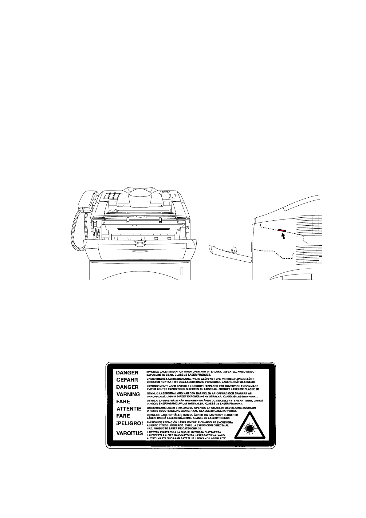
CAUTION FOR LASER PRODUCT (WARNHINWEIS FUR LASER DRUCKER)
CAUTION: When the machine during servicing is operated with the cover open, the
CAUTION: In case of any trouble with the laser unit, replace the laser unit itself. To
ACHTUNG: Im Falle von Störungen der Lasereinheit muß diese ersetzt werden. Das
<Location of the laser beam window>
SAFETY INFORMATION
regulations of VBG 93 and the performance instructions for VBG 93 are
valid.
prevent direct exposure to the laser beam, do not try to open the enclosure
of the laser unit.
Gehäuse der Lasereinheit darf nicht geöffnet werden, da sonst
Laserstrahlen austreten können.
ADDITIONAL INFORMATION
When servicing the optical system of the printer, be careful not to place a screwdriver or
other reflective object in the path of the laser beam. Be sure to take off any personal
accessories such as watches and rings before working on the printer. A reflected beam,
though invisible, can permanently damage the eyes.
Since the beam is invisible, the following caution label is attached on the laser unit.
x
Page 13
SERVICE MANUAL
DEFINITIONS OF WARNINGS, CAUTIONS AND NOTES
The following conventions are used in this service manual:
MFC-8220
WARNING
Indicates warnings that must be observed to prevent possible personal injury.
CAUTION:
!
Indicates cautions that must be observed to service the printer properly or prevent damage
to the printer.
NOTE:
Indicates notes and useful tips to remember when servicing the printer.
**Listed below are the various kinds of “WARNING” messages included in this manual.
WARNING
Always turn off the power switch and unplug the power cord from the power outlet
before accessing any parts inside the printer.
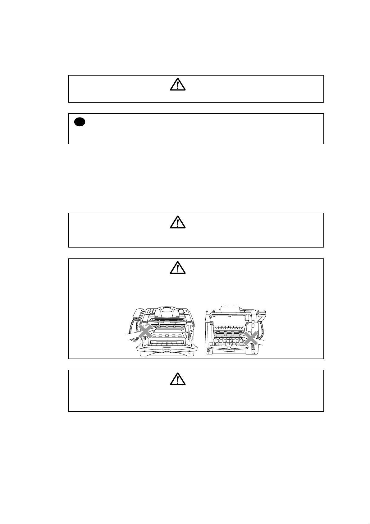
WARNING
Some parts inside the printer are extremely hot immediately after the printer is used.
When opening the front cover or back cover to access any parts inside the printer,
never touch the shaded parts shown in the following figures.
WARNING
If you analyze malfunctions with the power plug inserted into the power outlet,
special caution should be exercised even if the power switch is OFF because it is a
single pole switch.
xi
Page 14
CHAPTER 1 GENERAL
A
A
r
p
p)
A
j
1. OVERVIEW
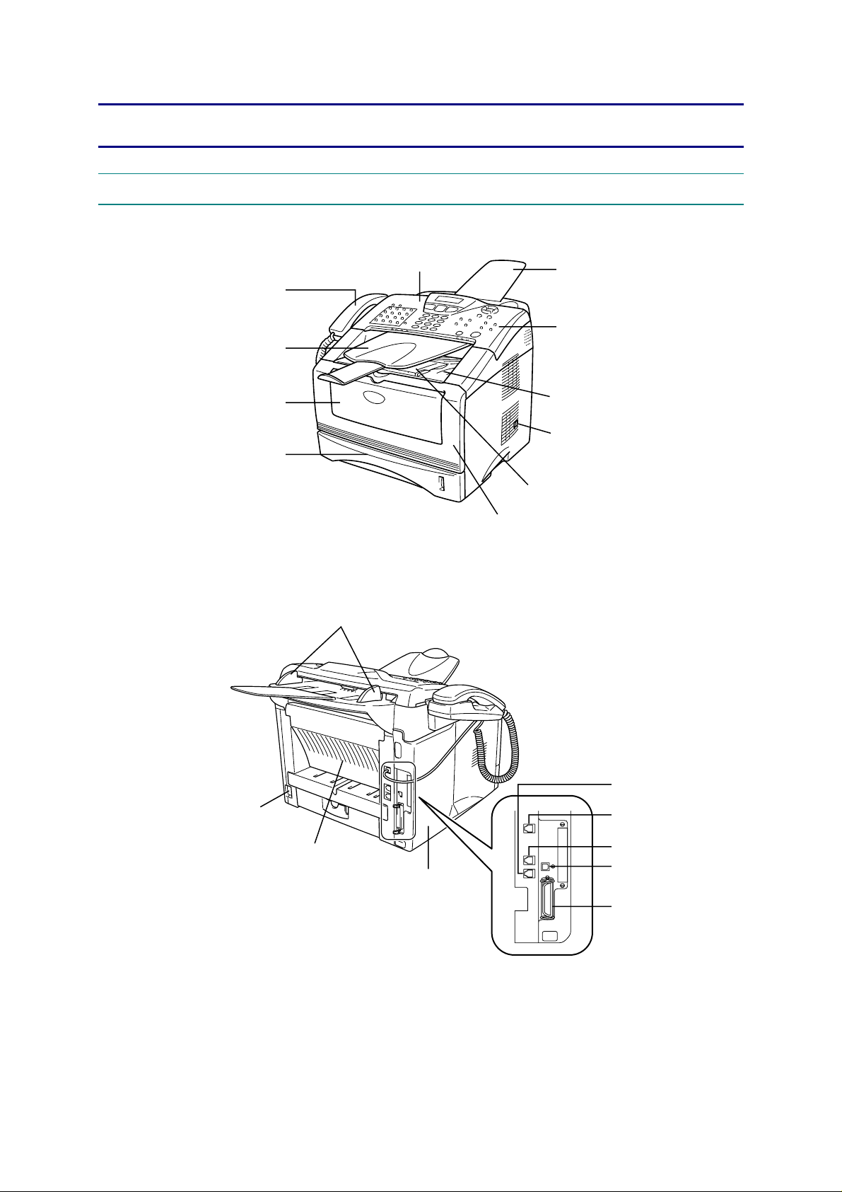
<Front View>
MFC-8220
SERVICE MANUAL
Telephone handset
DF document output support
Manual feed tray
Paper tray
<Back View>
Paper guides
Control panel
Fig. 1-1
Front cover
DF document support
Control panel cover
Face-down output tray
Power switch
Face-down output tray support
Fla
with extension (Support fla
External telephone line jack
C power connecto
Face-up output tray
(Back output tray)
Side cover
Handset
Telephone line jack
USB interface connector
Parallel interface connector
ack
Fig. 1-2
1-1
Page 15

CHAPTER 1 GENERAL
2. SPECIFICATIONS
2.1 General
Memory Capacity
Optional Memory
ADF
Paper Tray
Printer Type
LCD
Warm-up
Power Source
Power Consumption
Dimensions
Weight
Noise
32 MB
DIMM slot; Max. 160 MB
Up to 30 pages
250 Sheets (20lb)
Laser
16 characters x 2 lines
Max. 18 seconds at 73.4°F (23°C)
120V AC 50/60Hz (U.S.A., Canada Version only)
220 to 240V AC 50/60Hz (Europe Version only)
Average Operating (Copying): 440W or less, 25°C, Plain paper
Peak: 1090W or less
Sleep: 6W or less
Standby: 75W or less (25°C)
431 x 451 x 335 (mm) (U.S.A., Canada Version only)
375 x 451 x 335 (mm) (Europe Version only)
Without Drum/Toner Unit: 11.6kg
Operating: 53dBA or less
Standby: 30dBA or less
2.2 Environment of Installation Site
Temperature
Humidity
50 to 90.5°F (10 to 32.5°C)
20 to 80% (without condensation)
2.3 Paper
Paper Input
Paper Output
< Paper Tray >
• Paper type:
Plain paper, Transparency
• Paper size:
A4, Letter, JIS B5, A5, ISO B5, A6, LGL, ISO B6, EXE
Weight: 16 to 28lb (60 to 105g/m
• Maximum number of paper to be loaded:
Approx. 250 sheets of 20lb (80g/m
< Manual Feed Tray >
• Paper size:
Width: 20lb 2.75 to 8.66" (69.8 to 220.0mm)
Height: 4.60 to 14.02" (116.0 to 406mm)
Weight: 16 to 43lb (60 to 161g/m
• Maximum number of paper to be loaded on the manual feed tray:
1 sheet
Maximum number of sheets to be output to the delivery tray: In the
case of face-down delivery, up to 150 sheets of plain paper (80g/m
In the case of face-up delivery, up to 1 sheet of plain paper (80g/m
2
)
2
)
2
)
2
).
2
).
1-2
Page 16

2.4 Copy
Color/Monochrome
Copy Speed
Multiple Copies
Enlarge/Reduce
Resolution
2.5 Fax
Compatibility
Coding System
Modem Speed
Original Size
Scanning Width
Printing Width
Gray Scale
Polling Types
Contrast Control
Resolution
One-Touch Dial
Speed-Dial
Automatic Redial
Auto Answer
Memory
Transmission
Out of Paper
Reception
MFC-8220
SERVICE MANUAL
Monochrome
Up to 21cpm (Letter size) (U.S.A., Canada Version only)
Up to 20cpm (A4 size) (Europe Version only)
Up to 99 pages
25% to 400% (in increments of 1%)
600dpi
Super G3
MH/MR/MMR/JBIG
33600bps
ADF Width: 5.8" to 8.5" (148mm to 216mm)
ADF Height: 3.9" to 14.0" (100mm to 356mm)
208mm x 291mm
203mm x 291mm
256 levels
Standard, Confidential, Sequential, Timer
Automatic/Light/Dark (manual setting)
Horizontal: 203 dot/inch (8 dot/mm)
Vertical:
• Standard: 98 line/inch (3.85 line/mm)
• Fine, Photo: 196 line/inch (7.7 line/mm)
• Superfine: 392 line/inch (15.4 line/mm)
32 (16 x 2)
300 stations
Three times
0 to 10 rings
Up to 600 pages (Brother #1 Chart)
Up to 600 pages (Brother #1 Chart)
2.6 Specifications for Document Feeding System
2.6.1 Specifications for document
Length of document 100mm to 360mm
Width of document 148mm to 216mm
Weight of document
Thickness of document
1-3
ADF 64 to 90g/m2 (17 to 24lb)
1 sheet 52 to 90g/m
ADF 0.07mm to 0.12mm
1 sheet 0.06mm to 0.12mm
2
(14 to 24lb)
Page 17

CHAPTER 1 GENERAL
2.6.2 Specifications for ADF
ADF method Friction separation using round rollers and separation pads
Number of sheets
handled by ADF
(max)
*1: Be sure to place the edge of sheets in a wedge shape in the environment with
temperature of 20 to 30 degree C and humidity of 50 to 70%.
The maximum number of sheets is 20 in the other environments.
2.7 Printer
Printer Driver
Resolution
Print Speed
20lb 30 sheets (Letter) *1 XEROX 4024DP
24lb 20 sheets (Letter)
XEROX 4200 20lb 30 sheets (Letter) *1
®
Windows
95/98/98SE/Me/2000 Professional/XP/NT 4.0 Workstation
Version 4.0 driver supporting Brother Native Compression mode and
bi-directional capability
®
Apple
Macintosh® Quick Draw® Driver and PostScript (PPD) for OS
8.6-9.2/OS X 10.1/10.2.1 or Greater
HQ1200 (Max. 2400 x 600 dots/inch)
Up to 20cpm (A4 size)
2.8 Interfaces
Interface
Parallel cable
USB cable
NOTE:
• Please make sure that you use a Hi-Speed USB 2.0 certified cable if your computer uses a
Hi-Speed USB 2.0 interface.
• Even if your computer has a USB 1.1 interface you can connect the MFC.
• To meet FCC/CISPR emission requirements for the MFC, you must attach the included
filter core and cable tie to the parallel interface cable.
2.9 Consumable Items
Toner Cartridge Life
Expectancy
Drum Unit Life
Expectancy
Recommended Cable
A bi-directional shielded parallel cable that is IEEE 1284 compliant
and not longer than 6 feet (2m).
A Hi-Speed USB 2.0 cable that is not longer than 6 feet (2m).
TN-540/TN-3030: Standard toner cartridge - Up to 3,500* pages
TN-570/TN-3060: High yield toner cartridge - Up to 6,700* pages
*(when printing letter size or A4 paper at 5% print coverage)
NOTE:
Toner life expectancy will vary depending upon the type of average
print job.
Up to 20,000 pages
NOTE:
There are many factors that determine the actual drum life, such as
temperature, humidity, type of paper, toner you use and number of
pages per print job.
1-4
Page 18

2.10 Network
Interface 10/100 Base TX Ethernet (automatic)
Protocol TCP/IP (RARP, BOOTP, DHCP, APIPA, NetBIOS, WINS, SSDP,
Control Web Based Management (HTTPD)
Update of Programs Flash ROM base
Supplied Software BRAdmin Professional (when using Windows
2.11 Paper
SERVICE MANUAL
Rendezvous, LPR/LPD, Port9100, POP3/SMTP, SMB, IPP, FTP,
TELNET, SNMP, HTTP, TFTP), Netware IPX/SPX (Bindery and
NDS), Apple Talk, DLC/LLC
BRAdmin Professional (TCP/IP or IPX/SPX is used)
SNMP, Brother's original MIB in compliance with MIBII
TELNET command console
Web BRAdmin
Upgrade using TFTP/FTP protocols is available.
Upgrade using IPX/SPX protocols is available.
Upgrade using the Brother BRAdmin utility is available.
®
®
NT 4.0/ Windows
Port drivers supporting Windows
Windows
®
2000
LRP port drivers (when using Windows
2000/XP)
®
95/98/Me, Windows® NT 4.0/
®
4.0)
NetBIOS port drivers (when using Windows
NT 4.0/ Windows
SMTP port driver (when using Windows
4.0/ Windows
®
2000/XP)
®
2000/XP)
95/98/Me, Windows®
95/98/Me, Windows® NT
®
95/98/Me, Windows®
®
95/98/Me, Windows® NT
Web BRAdmin Professional (Not included in the CD-ROM.
Uploaded to the Web site.) For more information on Web BRAdmin
Professional, please access http://solutions.brother.co.jp.
MFC-8220
2.11.1 Feedable paper
(1) Type
Type Paper tray
Plain paper
60 to 105 g/m
2
(16 to 28lb)
Recycled paper
Bond paper
Thick paper
105g/m
2
to 161g/m
(28 to 43lb)
Transparency
Labels
Envelope
Post card
2
Manual
(Tray #1)
feed tray
〇 〇 〇
〇
〇
〇
〇
〇
up to 10
sheets
〇
A4 or Letter
〇
A4 or Letter
〇
〇
Lower tray
Selection from printer driver
(Tray #2)
Plain paper or rather thick plain
paper
〇
Plain paper or rather thick plain
paper
Bond paper
Thick paper (Post card) or
extra thick paper
OHP
Plain paper or rather thick plain
paper
Envelope, thick envelope, thin
envelope
Thick paper (Post card) or
extra thick paper
1-5
Page 19
CHAPTER 1 GENERAL
(2) Size
Size
(3) Other specifications
<In the case of Paper Tray>
<In the case of Manual Feed Tray>
(4) Recommended paper
Paper tray (Tray #1) Manual feed tray Lower tray (Tray #2)
A4, Letter, JIS B5, ISO B5,
ISO B6, A5, A6, Legal,
Executive
Plain paper (Recycled paper)
Weight 60 to 105 g/m2
Thickness 0.08 to 0.13 mm
Moisture content 4 to 6% of weight
Plain paper Envelope
Weight 60 to 161g/m2
Thickness 0.08 to 0.2mm
Moisture content 4 to 6% of weight 4 to 6% of weight
Plain Paper
Transparency
Labels
Horizontal:
69.8 to 220.0mm
Vertical:
116.0 to 406.0mm
Plain paper: Xerox 4200 20lb
Hammermill Laser Paper 24lb
3M CG 3300
Avery laser label # 5160
A4, Letter, JIS B5, ISO B5, ISO
B6, A5, Legal, Executive
75 to 90g/m
equivalent to one sheet
0.084 to 0.12mm
equivalent to one sheet
2
CAUTION:
!
When you are choosing print media, be sure to follow the information given below to prevent
any paper jams, print quality problems or machine damage;
• It is recommended to use long-grained paper for the best print quality. If short-grained
paper is being used, it might be the cause of paper jams.
• Use neutral paper. Do not use acid paper to avoid any damage to the drum unit.
• Avoid using coated paper such as vinyl coated paper.
• Avoid using preprinted or highly textured paper.
• It is recommended to use labels or transparencies which are designed for use in laser
printers.
• Avoid feeding labels with the carrier sheet exposed, or the machine will be damaged.
• Before loading paper with holes such as organizer sheets, be sure to fan the stack well.
• Do not use organizer sheets that are stuck together. The glue that is used might caused
damaged to the machine.
• When printing on the back of pre-printed paper, if the paper is curled, be sure to straighten
the paper as much as possible.
• Different types of paper should not be loaded at the same time in the paper tray to avoid
any paper jams or misfeeds.
1-6
Page 20
2.11.2 Paper capacity
Paper tray (Tray #1) Manual feed tray Lower tray (Tray #2)
Paper capacity 250 sheets (80g/m2) 1 sheet 250 sheets (80g/m2)
2.11.3 Paper output
(1) Face-down output tray
Output capacity: Max. 150 sheets (80g/m
(2) Face-up output tray
Output capacity: Max. 1 sheet (80g/m
Hint:
Face-down output: Output paper with its printed surface turned down
Face-up output: Output paper with its printed surface turned up
(3) The output methods according to paper types as shown below are recommended.
Paper types
Plain paper
Thick paper
Recycled paper
Transparency
Label
Envelope
Post card
2
)
Only in the case of face-down output
2
)
Only in the case of face-up output
Paper output
Face-down output Face-up output
〇 〇
〇
〇 〇
〇
〇
〇
〇
MFC-8220
SERVICE MANUAL
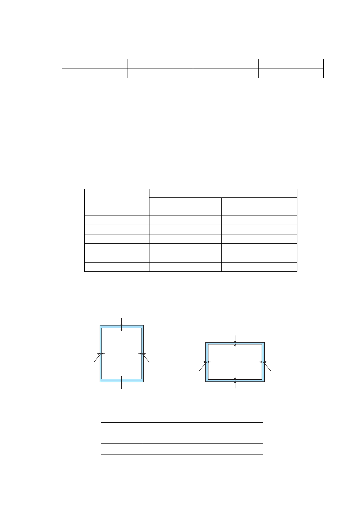
2.12 Printable Area
Unprintable areas (edge) of recording paper by size are shown below. Areas excluding the
edge measurement from recording paper size are printable areas.
2
1
1
3
2
4
A4, Letter, B5, A5, A6, Post card
1 4.2mm (50 dots with the 300dpi mode)
2 4.2mm (50 dots with the 300dpi mode)
3 4.2mm (50 dots with the 300dpi mode)
4 4.2mm (50 dots with the 300dpi mode)
4
3
1-7
Page 21
CHAPTER 1 GENERAL
2.13 Print Speeds with Various Settings
Print speed of the machine is up to 18cpm when loading A4 size paper from the paper tray in
the plain paper mode.
Actual print speed varies depending on the paper type or paper size as shown in the tables
below;
< Letter or A4 size >
Mode setting Print speed
OHP
Plain paper
Rather thick plain paper/Thin envelope
Thick paper (Post card)/Envelope
Extra thick paper/Bond paper/ Rather thick envelope
< Smaller size than Letter or A4 >
Mode setting Print speed
OHP
Plain paper
Rather thick plain paper/Thin envelope
Thick paper (Post card)/Envelope
Extra thick paper/Bond paper/ Rather thick envelope
*The print speed may vary according to conditions, such as paper size and paper tray.
NOTE:
• When a smaller size paper than A4 size is printed, the temperature on both edges of the
fixing unit is much higher than the temperature on the center of the unit where the paper is
fed depending on the setting or model. Therefore, the print speed is slowed in order to
decrease the temperature on the edges after the specified time, it is maximum print speed
when you first start printing.
• Max. speed is 20 cpm or more. It varies depending on the paper size.
21cpm (Letter), 20cpm (A4)
21cpm (Letter), 20cpm (A4)
21cpm (Letter), 20cpm (A4)
21cpm (Letter), 20cpm (A4)
4cpm *
21cpm (Letter), 20cpm (A4)
21cpm (Letter), 20cpm (A4)
8cpm after 5 min. have passed.
8cpm after 30 sec. have passed.
4cpm *
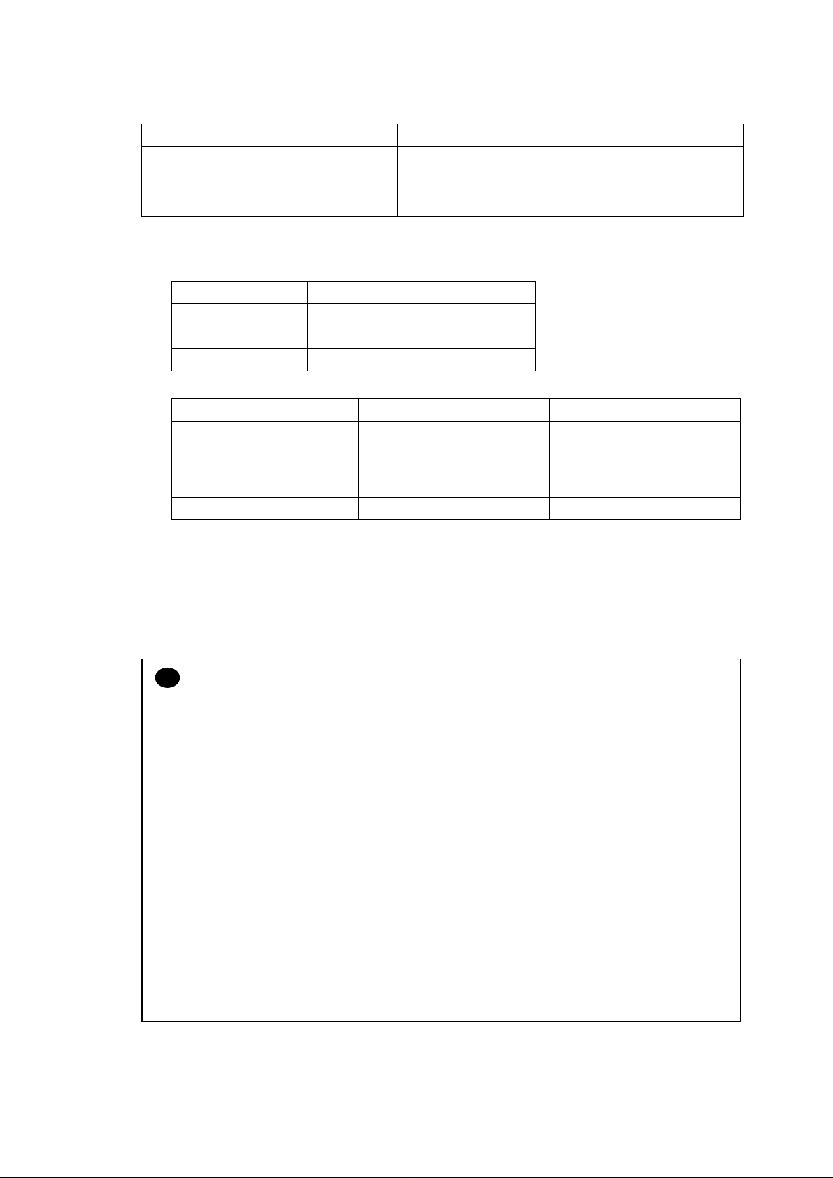
2.14 Toner Cartridge Weight Information
Toner cartridge weight (approx weight)
Brand new toner cartridge weight 827.5g 772.5g
Toner weight at brand new toner cartridge 197.5±2.5g 142.5±2.5g
Toner cartridge weight at toner near empty 693.5 to 698.5g 693.5 to 698.5g
Remain toner weight at toner near empty 80 to 85g 80 to 85g
Toner cartridge weight at toner empty 678.5 to 683.5g 678.5 to 683.5g
Remain toner weight at toner empty 65 to 70g 65 to 70g
You can print 500 to 600 pages with 10g toner.
*Without yellow protector
*Toner cartridge weight may vary within 2 to 3g depending on the cartridge weight.
1-8
TN3060/TN570 TN3030/TN540
Page 22

3. SERIAL NO. DESCRIPTIONS
The descriptions below show how to understand the meanings of the numbers printed on the
labels or bag of the machine and machine parts:
< ID for production month >
A: January B: February C: March D: April
E: May F: June G: July H: August
J: September K: October L: November M: December
< ID for year >
3: 2003 4: 2004
< ID for factory >
9: Kariya Plant A: Mie Brother C: BIUK
J: Buji Nan Ling Factory
(1) Machine: Printed on the label attached on the rear of the main body
<Example>
<MODEL NO.>
MFC-8220
SERVICE MANUAL
<
>
U 5 2 6 8 2 A 3 J 1 1 1 1 0 1
FACTORY ID NO.
YEAR
MONTH
(2) Process unit: Imprinted on the aluminum bag
(Drum unit with toner cartridge)
SEQUENTIAL NO.
3 A 1 1 J A
(3) Drum unit: Printed on the bar code label attached inside the drum unit
YEAR
MONTH
DATE
PRODUCTION LINE NO.
FACTORY ID NO.
A 3 9 5 1 0 0 1 0 4 A
MONTH
YEAR
SERIAL NO.
TONER VOLUME
FACTORY ID NO.
PRODUCTION LINE NO.
DR/TN REUSE
The first time: M
The second time: N
The third time: P
1-9
Page 23

CHAPTER 1 GENERAL
(4) Toner cartridge: Imprinted on the aluminum bag
(5) Laser unit: On the laser unit
3 A 3 0 J
YEAR
MONTH
DATE
FACTORY ID NO.
Printed on the bar code label attached on the toner cartridge
CARTRIDGE
PRODUCTION INFO.
M 3 9 A 0 0 0 1 9 9 A
MONTH
YEAR
FACTORY ID NO.
SERIAL NO.
TONER VOLUME
PRODUCTION LINE NO.
DR/TN REUSE
The first time: M
The second time: N
The third time: P
2 5 0 0 1
LASER UNIT NO. 5: LM2486001 Laser Unit ZL2E
FACTORY ID NO.
PRODUCTION LOT NO.
1: Kariya Plant
2: Buji Nan Ling Factory
1-10
Page 24

CHAPTER 2 INSTALLATION AND BASIC OPERATION
1. CONDITIONS REQUIRED FOR INSTALLATION
1.1 Power Supply
• The source voltage must stay within ±10% of the rated voltage shown on the rating plate.
• The power cord, including extensions, should not exceed 5 meters (16.5 feet).
• Do no share the same power circuit with other high-power appliances, particularly an air
conditioner, copier or shredder. If it is unavoidable that you must use the machine with
these appliances, it is recommended that you use an isolation transformer or a highfrequency noise filter.
• Use a voltage regulator if the power source is not stable.
1.2 Environment
• The machine should be installed near a power outlet, which is easily accessible.
• The room temperature is maintained between 10°C and 32.5°C. The relative humidity is
maintained between 20% and 80%.
• The machine should be used in a well ventilated room.
• Place the machine on a flat, horizontal surface.
• Keep the machine clean. Do not place the machine in a dusty place.
• Do not place the machine where the ventilation hole of the machine is blocked. Keep
approximately 100 mm (4 inches) between the ventilation hole and the wall.
• Do not place the machine where it is exposed to direct sunlight. Use a blind or a heavy
curtain to protect the machine from direct sunlight when the machine is unavoidably set up
near a window.
• Do not place the machine near devices that contain magnets or generate magnetic fields.
• Do not subject the machine to strong physical shocks or vibrations.
• Do not expose the machine to open flames or salty or corrosive gasses.
• Do not place objects on top of the machine.
• Do not place the machine near an air conditioner.
• Keep the machine horizontal when carrying.
• Do not cover the slots in the side cover.
SERVICE MANUAL
MFC-8220
2-1
Page 25

CHAPTER 2 INSTALLATION AND BASIC OPERATION
1.3 System Requirements for Brother Printer Solution
Check the following system requirements to setup and operate the printer using Brother
Printing Solution:
Computing System
Operating System Version
Windows®
Operating
System
95, 98, 98SE 488/66 MHz 8MB 16MB 40MB
NT
Workstation
4.0
2000
Professional
Me Pentium 150MHz 32MB 64MB 50MB
XP Pentium 300MHz 128MB 128MB 50MB
OS 8.6 to 9.2 32MB 64MB Apple
Macintosh
Operating
System
OS X 10.1 to
10.2.1
Processor Speed Minimum
RAM
Recommended
RAM
Available
Hard Disk
Space
Pentium 75MHz 16MB 32MB 50MB
Pentium 133MHz 64MB 128MB 50MB
All base models
meet minimum
system
128MB 160MB
50MB
requirements
2-2
Page 26
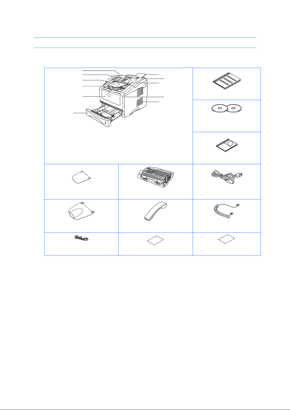
2. UNPACKING
When unpacking the machine, check to see that all of the following components are included
in the carton.
SERVICE MANUAL
MFC-8220
MFC
11
2
3
4
5
56
1. Control Panel
2. Telephone Handset
3. ADF Document Output Support
4. Face-down Output Tray Support
Flap with Extension (Support Flap)
5. Manual Feed Tray
ADF Document Support
7
8
9
10
11
6. Paper Tray
7. ADF Document Support
8. Control Panel Cover
9. Face-down Output Tray
10. Front Cover
11.Pow er Switch
Drum Unit Assembly
(including T oner Cartridge)
Quick Setup Guide
CD-ROMs
For Windows
For Macintosh
®
®
User's Guide
Pow er Cord
ADF Document Output Support
Telephone Line Cord
Telephone Handset
(U.S.A. / Canada only)
Test Sheet (U .S.A. only)
Fig. 2-1
Handset Curled Cord
(U.S.A. / Canada only)
Accessory Order Form
(U.S.A. / Canada only)
Carton components may differ from one country to another.
Save all packing materials and the carton.
NOTE:
• The interface cable is not a standard accessory. Please purchase the appropriate
interface cable for the interface you intend to use (Parallel or USB).
• For Parallel use a bi-directional shield interface cable that is IEEE 1284-compliant, and not
longer than 6 feet (2 meters).
• For USB: use a Hi-Speed USB 2.0 interface cable that is not longer than 6 feet (2 meters).
• Please make sure that you use a Hi-Speed USB 2.0 certified cable if your computer uses
a Hi-Speed USB 2.0 interface.
• Even if your computer has a USB 1.1 interface, you can connect the machine.
2-3
Page 27

CHAPTER 2 INSTALLATION AND BASIC OPERATION
CAUTION:
When you move the machine, grasp the side handholds that are at the bottom shown in the
illustration.
2-4
Page 28

3. INSTALL THE MACHINE
You need to implement hardware setup and driver installation to use the machine.
Firstly, identify the Operating System on your computer. (Windows
4.0/ Windows
(Parallel, USB or Network) for your computer. Most existing parallel cables support bidirectional communication, but some might have an incompatible pin assignment or may not
be IEEE 1284-compliant.
The installation programs for the hardware setup and driver installation are contained on the
supplied CD-ROM.
3.1 For All Users
For Windows
(1) Turn on the PC power. Insert the supplied CD-ROM into the CD-ROM drive. The
opening screen will appear automatically. Follow the on-screen instructions.
NOTE:
If the opening screen does not appear; click Start and select Run. Then, enter the CD-drive
letter and type \START.EXE (for example: D:\START.EXE).
(2) Click the Initial Setup icon on the menu screen.
(3) You can view the Initial Setup instructions.
For Macintosh
®
2000/XP and Macintosh) Then, purchase the appropriate interface cable
ââââ
users
ââââ
users
SERVICE MANUAL
®
95/98/Me, Windows® NT
MFC-8220
(1) Turn on the Macintosh. Insert the CD-ROM into the CD-ROM drive.
(2) Double click the Start Here! icon or Start Here OS X icon. Follow the on-screen
instructions.
(3) Click the Initial Setup icon on the menu screen.
(4) You can view the Initial Setup instructions.
2-5
Page 29
CHAPTER 2 INSTALLATION AND BASIC OPERATION
A
A
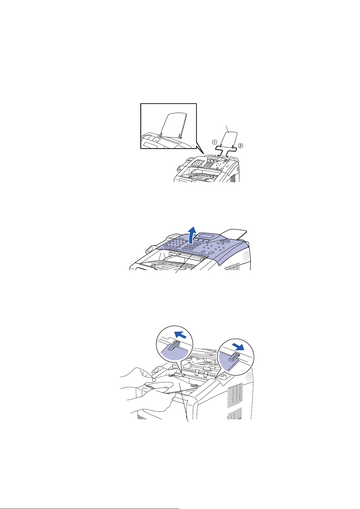
3.1.1 Attaching the Supports
NOTE:
Do not connect the interface cable. Connecting the interface cable is done when installing the
driver.
(1) Attach the ADF document support.
DF document support
Fig. 2-2
(2) Open the control panel cover by lifting it toward the back.
Control panel cover
Fig. 2-3
(3) Attach the ADF support.
DF document output support
Fig. 2-4
(4) Close the control panel cover.
2-6
Page 30
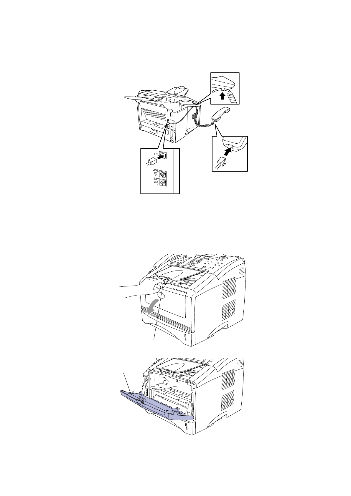
3.1.2 Installing the Handset
(1) Connect the curled handset cord to the machine and the other end to the handset.
(U.S.A. / Canada only)
SERVICE MANUAL
MFC-8220
3.1.3 Installing the Drum Unit Assembly
(1) Open the front cover by pressing the front cover release button.
Front cover release button
Fig. 2-5
Front cover
Fig. 2-6
2-7
Page 31

CHAPTER 2 INSTALLATION AND BASIC OPERATION
(2) Unpack the drum unit assembly. Remove the protective part.
Drum unit assem bl y
Protective part
Fig. 2-7
(3) Rock it from side to side several times to distribute the toner evenly inside the assembly.
Fig. 2-8
(4) Push the drum unit assembly into the machine (until it snaps into place).
Fig. 2-9
(5) Close the front cover of the machine.
Fig. 2-10
2-8
Page 32

3.1.4 Load Paper in the Paper Tray
(1) Pull the paper tray completely out of the machine.
(2) While pressing the paper guide release lever, slide the adjusters to fit the paper size.
Check that the guides are firmly in the slots on the tray.
SERVICE MANUAL
MFC-8220
Fig. 2-11
Paper guide release lever
Fig. 2-12
NOTE:
For Legal size paper, press the universal guide release button and pull out the rear of the
paper tray.
Universal guide release button
Fig. 2-13
2-9
Page 33

CHAPTER 2 INSTALLATION AND BASIC OPERATION
(3) Fan the stack of paper well to avoid paper jams and misfeeds.
(4) Put paper in the paper tray. Check that the paper is flat in the tray and below the
maximum paper mark.
Fig. 2-14
Up the here
Fig. 2-15
(5) Put the paper tray firmly back in the machine and unfold the support flap before you use
the machine.
Support flap
Fig. 2-16
NOTE:
For details on supported paper specifications, see “About paper” in Chapter 2 of the User’s
Guide.
2-10
Page 34

3.1.5 Installing the Power Cord and Phone Line
NOTE:
Do not connect the Parallel or USB cable yet.
(1) Make sure that the power switch is off. Connect the power cord to the machine.
Fig. 2-17
(2) Plug the power cord into an AC outlet. Turn the power switch on.
SERVICE MANUAL
MFC-8220
Power cord
Fig. 2-18
(3) Connect one end of the telephone line cord to the jack on the machine marked LINE and
the other end to a modular wall jack.
Fig. 2-19
* MJ cover is only equipped for Europe spec .
WARNING
- The machine must be grounded using a 3-prong plug.
- Since the machine is grounded through the power outlet, you can protect yourself from
potentially hazardous electrical conditions on the telephone network by keeping the power to
your machine on when you connect it to a telephone line. Similarly, you can protect yourself
when you want to move your machine by disconnecting the telephone line first and then the
power cord.
2-11
Page 35

CHAPTER 2 INSTALLATION AND BASIC OPERATION
NOTE:
If you are sharing one phone line with an external telephone, connect it as shown below.
NOTE:
- If you are sharing one phone line with an external telephone answering device, connect it as
shown below.
Fig. 2-20
- Please set the receive mode to External TAD.
- For more details, see “Connecting the MFC” in Chapter 1 of the User’s Guide.
TAD
TAD
Fig. 2-21
2-12
Page 36

SERVICE MANUAL
3.2 Installing the Driver & Software
3.2.1 For USB Interface Cable Users (For Windows® 98/98SE/Me/2000 Professional/XP)
(1) Switch off and unplug the machine from the AC outlet and disconnect it from your
computer, if you already connected an interface cable.
MFC-8220
(2) Turn on your computer.
®
(For Windows
(3) Insert the supplied CD-ROM for Windows
2000 Professional/XP, you must be logged on as the administrator.)
®
into your CD-ROM drive. If the model name
screen appears, select your machine. If the language screen appears, select your
language.
(4) The CD-ROM main menu will appear.
Click Install Software.
NOTE:
If this window does not appear, use Windows
®
Explore to run the setup.exe program
from the root directory of the Brother CD-ROM.
(5) Click MFL-Pro Suite in Main Application.
NOTE:
• MFL-Pro Suite includes Printer Driver, Scanner Driver, ScanSoft
ScanSoft
• PaperPort
• ScanSoft
®
Text Bridge®, PC-FAX software, Remote Setup and True Type fonts.
®
is a document management application for viewing scanned documents.
®
TextBridge®, which is integrated into PaperPort®, is an OCR application that
®
PaperPort ®,
converts an image into text and inserts it into your default word processor.
(6) Click Install.
NOTE:
• If you see the following screen, click OK to install the Windows
®
updates. After the
updates are installed your PC may restart.
• If it does the installation will automatically continue.
• If the installation does not continue automatically, please open the installer menu again
by double-clicking the setup.exe program from the root directory of the Brother CDROM, and continue from Step (4).
(7) When the PaperPort 8.0 SE Setup window is displayed, click Next.
(8) After reading and accepting the ScanSoft
®
License Agreement, enter your user
information and click Next.
(9) Select Typical and click Next.
®
(10) Click Install and PaperPort
will start installing on your computer.
(11) When the PaperPort 8.0 SE Registration screen is displayed, make your selection and
follow the on-screen instructions.
(12) Click Finish to complete installation.
(13) When the Brother MFL-Pro Suite Installation window appears, click Next.
NOTE:
• If an error message appears at this point in the installation process, or if you have
previously installed the MFL-Pro Suite, you will first have to uninstall it.
• From the Start menu, select Programs, Brother, Brother MFL-Pro Suite, Uninstall,
and then follow the instructions on the screen.
(14) When the Brother Software License Agreement window appears, click Yes.
2-13
Page 37

CHAPTER 2 INSTALLATION AND BASIC OPERATION
(15) Select Local Interface, and then click Next.
(16) Select Standard, and then click Next. The application files will be copied and installed to
your computer.
NOTE:
• If you want to install the PS Brother (PostScript
follow the on-screen instructions.
• When the Select Components screen appears, check PS Printer Driver, and then
continue following the on-screen instructions.
< For Windows
®
98/98SE/Me Users Only >
Make sure that you followed the instructions in (1) to (16) on pages 2-13 to 2-14.
(17) When this screen appears, connect the USB interface cable to your PC, and then
connect it to the machine.
Plug the machine into the AC power outlet. Turn the power switch on.
It will take a few seconds for the installation screen to appear.
The installation of the Brother drivers will automatically start. Follow the instructions on
the screen.
®
) driver, select Custom and then
(18) Select BRUSB: USB Printer Port, and then click Next.
(19) Accept the default Printer name by selecting Yes, and then click Next.
(20) Select Yes (recommended), and then click Finish. A test page will be printed so you
can check the print quality.
(21) If the test page is printed correctly, click Yes. If you click No, follow the prompts on the
screen to correct the problem.
NOTE:
If the README file shown in step (22) appears, close the README.WRI file and then
click Finish after printing the page.
(22) The README file will be displayed. Please read this file for troubleshooting information
and then close the file to continue installation.
(23) Check the Run On-Line Regis tration and then click Next.
(24) Click Finish to restart your computer.
(25) After the computer restarts, click Yes to have the Control Center load each time
Windows
®
is started. The Control Center will appear as an icon in the task tray.
If you click No the Scan key on the machine will be disabled.
NOTE:
Even if you select NO, you will be able to launch the Brother Control Center later to use
the Scan key by double-clicking the Smart UI icon on the desktop. This loads the
Brother Control Center to the task tray. See AutoLoad the Brother Control Center,
Chapter 4 in the Documentation (Software User’s Guide) located on the CD-ROM.
OK:
The Brother PC-FAX, Printer and Scanner drivers have been installed and the
installation is now complete.
2-14
Page 38

SERVICE MANUAL
®
< For Windows
2000 Professional Users Only >
Make sure that you followed the instructions in (1) to (16) on pages 2-13 to 2-14.
(17) When this screen appears, connect the USB interface cable to your PC, and then
connect it to the machine.
Plug the machine into the AC power outlet. Turn the power switch on.
It will take a few seconds for the installation screen to appear.
The installation of the Brother drivers will automatically start. Follow the instructions on
the screen.
(18) If the Digital Signature Not Found dialog boxes appear, click Yes to install the driver.
(19) The README file will be displayed.
Please read this file for troubleshooting information and then close the file to continue
installation.
(20) Check the Run On-Line Registration and then click Next.
(21) Click Finish to restart your computer.
MFC-8220
(22) After the computer restarts, click Yes to have the Control Center load each time
Windows
®
is started. The Control Center will appear as an icon in the task tray.
If you click No the Scan keys on the machine will be disabled.
NOTE:
Even if you select NO, you will be able to launch the Brother Control Center later to use
the Scan key by double-clicking the Smart UI icon on the desktop. This loads the
Brother Control Center to the task tray. See AutoLoad the Brother Control Center,
Chapter 4 in the Documentation (Software User’s Guide) located on the CD-ROM.
OK:
A Basic Universal printer driver was installed with the MFL-PRO Software Suite which is
certified for use with Windows® operating systems.
Brother also offers a fully featured printer driver (Native driver) that includes more
features than the Basic Universal driver. However, this driver does not include a
Windows® certificate. To install the Brother Native driver proceed to step (23).
NOTE:
For details on what features are available, see chapter 2 of the Software User's Guide.
Brother Native driver Installation
(23) Click Start and select Settings and then Printers. Click on Add Printer and the Add
Printer Wizard will start.
When this screen appears, click Next.
(24) Un-check the Automatically detect and install my Plug and Play printer selection
and then click Next.
(25) Select USBXXX from the pull down window for the Printer Port Selection and then click
Next.
(26) Click on Have Disk.
(27) Browse the CD-ROM and highlight your language folder and click Open.
Highlight the W2K folder and click Open.
Highlight the Addprt folder and click Open.
(28) Click Open.
2-15
Page 39

CHAPTER 2 INSTALLATION AND BASIC OPERATION
(29) Make sure X: \ENG\W2K\Addprt is displayed in the window and click OK (X:\ is the
drive letter of your CD-ROM).
(30) Highlight the model you are installing from the list of machines and click Next.
NOTE:
Make sure you select a USB printer.
(31) The model you are installing will be listed in the window. Select Yes or No if you want
this driver to be your default printer and then click Next.
(32) If this screen appears, select Do not share this printer and Next.
(33) Select Yes and Next to print a test page.
(34) When this screen appears, click Finish.
(35) If the Digital Signature Not Found dialog box appears, click Yes.
(36) If the test page printed, click OK.
NOTE:
• There will be two Brother printer drivers listed in the Printers selection.
• The driver with "Printer" after the model name (ex. Brother MFC-8220 Printer) is the
Brother Native Driver.
OK:
The Brother Native Drivers have been installed and the installation is now complete.
< For Windows
®
XP Users Only >
Make sure that you followed the instructions in (1) to (16) on pages 2-13 to 2-14.
(17) When this screen appears, connect the USB interface cable to your PC, and then
connect it to the machine.
Plug the machine into the AC power outlet. Turn the power switch on.
It will take a few seconds for the installation screen to appear.
The installation of the Brother drivers will automatically start. The screen appears one
after another, please wait for a while.
(18) The README file will be displayed.
Please read this file for troubleshooting information and then close the file to continue
installation.
(19) Check the Run On-Line Registration and then click Next.
(20) Click Finish to restart your computer.
OK:
A Basic Universal printer driver was installed with the MFL-PRO Software Suite which is
certified for use with Windows® operating systems.
Brother also offers a fully featured printer driver (Native driver) that includes more
features than the Basic Universal driver. However, this driver does not include a
Windows® certificate. To install the Brother Native driver proceed to step (21).
NOTE:
For details on what features are available, see chapter 2 of the Software User's Guide.
2-16
Page 40

SERVICE MANUAL
Brother Native driver Installation
(21) Click Start and select Printers and Faxes.
Click on Add a printer and the Add Printer Wizard will start.
When this screen appears, click Next.
(22) Un-check the Automatically detect and install my Plug and Play printer selection
and then click Next.
(23) Select USBXXX from the pull down window for the Printer Port Selection and then click
Next.
(24) Click on Have Disk.
(25) Browse the CD-ROM and highlight your language folder and click Open.
Highlight the WXP folder and click Open.
Highlight the Addprt folder and click Open.
(26) Click Open.
(27) Make sure X: \ENG\W2K\Addprt is displayed in the window and click OK (X:\ is the
drive letter of your CD-ROM).
(28) Highlight the model you are installing from the list of machines and click Next.
MFC-8220
NOTE:
Make sure you select a USB printer.
(29) The model you are installing will be listed in the window. Select Yes or No if you want
this driver to be your default printer and then click Next.
(30) If this screen appears, select Do not share this printer and Next.
(31) Select Yes and Next to print a test page.
(32) When this screen appears, click Finish.
(33) When this screen appears, click Continue Anyway.
NOTE:
• There will be two Brother printer drivers listed in the “Printers” selection.
• The driver with Printer after the model name (ex. Brother MFC-8220 Printer) is the
Brother Native Driver.
OK:
The Brother Native Drivers have been installed and the installation is now complete.
2-17
Page 41

CHAPTER 2 INSTALLATION AND BASIC OPERATION
3.2.2 For Parallel Interface Cable Users (For Windows
(1) Switch off and unplug the machine from the AC outlet and disconnect it from your
computer, if you already connected an interface cable.
®
95/98/98SE/Me/2000 Professional/XP)
(2) Turn on your computer.
®
(For Windows
(3) Insert the supplied CD-ROM for Windows
2000 Professional/XP, you must be logged on as the administrator.)
®
into your CD-ROM drive. If the model name
screen appears, select your machine. If the language screen appears, select your
language.
(4) The CD-ROM main menu will appear.
Click Install Software.
NOTE:
If this window does not appear, use Windows
®
Explore to run the setup.exe program from
the root directory of the Brother CD-ROM.
(5) Click MFL-Pro Suite in Main Application.
NOTE:
• MFL-Pro Suite includes Printer Driver, Scanner Driver, ScanSoft
ScanSoft
PaperPort
• ScanSoft
®
Text Bridge®, PC-FAX software, Remote Setup and True Type fonts.
®
is a document management application for viewing scanned documents.
®
TextBridge®, which is integrated into PaperPort ®, is an OCR application that
®
PaperPort®,
converts an image into text and inserts it into your default word processor.
(6) Click Install.
NOTE:
• If you see the following screen, click OK to install the Windows
®
updates. After the
updates are installed your PC may restart.
• If it does the installation will automatically continue.
• If the installation does not continue automatically, please open the installer menu again
by double-clicking the setup.exe program from the root directory of the Brother CDROM, and continue from step (4).
(7) When the PaperPort 8.0 SE Setup window is displayed, click Next.
(8) After reading and accepting the ScanSoft
®
License Agreement, enter your user
information and click Next.
(9) Select Typical and click Next.
®
(10) Click Install and PaperPort
will start installing on your computer.
(11) When the PaperPort 8.0 SE Registration screen is displayed, make your selection and
follow the on- screen instructions.
(12) Click Finish to complete installation.
(13) When the Brother MFL-Pro Suite Installation window appears, click Next.
NOTE:
If an error message appears at this point in the installation process, or if you have
previously installed the MFL-Pro Suite, you will first have to uninstall it. From the Start
menu, select Programs, Brother, Brother MFL-Pro Suite, Uninstall, and then follow
the instructions on the screen.
2-18
Page 42

(14) When the Brother Software License Agreement window appears, click Yes.
(15) Select Local Interface, and then click Next.
(16) Select Standard, and then click Next. The application files will be copied to your
computer.
SERVICE MANUAL
MFC-8220
NOTE:
®
If you want to install the PS Brother (PostScript
) driver, select Custom and then follow
the on-screen instructions. When the Select Components screen appears, check PS
Printer Driver, and then continue following the on-screen instructions.
< For Windows
®
95/98/98SE/Me Users Only >
Make sure that you followed the instructions in (1) to (16) on pages 2-18 to 2-19.
(17) When this screen appears, connect the parallel interface cable to your PC, and then
connect it to the machine.
Plug the machine into the AC power outlet. Turn the power switch on.
Caution
Do not plug the power cord before connecting the parallel interface cable. It may cause
damage to your machine.
(18) Click Next.
(19) The README file will be displayed.
Please read this file for troubleshooting information and then close the file to continue
installation.
(20) Check the Run On-Line Registration and then click Next.
(21) Click Finish to restart your computer.
(22) After the computer restarts, the installation of the Brother drivers will automatically start.
Follow the instructions on the screen.
(23) Click Yes to have the Brother MFL-Pro Control Center load each time Windows
®
is
started. The Control Center will appear as an icon in the task tray.
If you click No the Scan key on the machine will be disabled.
NOTE:
Even if you select NO, you will be able to launch the Brother Control Center later to use
the Scan key by double-clicking the Smart UI icon on the desktop. This loads the
Brother Control Center to the task tray. See AutoLoad the Brother Control Center,
Chapter 4 in the Documentation (Software User’s Guide) located on the CD-ROM.
OK:
The Brother PC-FAX, Printer and Scanner drivers have been installed and the
installation is now complete.
2-19
Page 43

CHAPTER 2 INSTALLATION AND BASIC OPERATION
®
< For Windows
2000 Professional Users Only >
Make sure that you followed the instructions in (1) to (16) on pages 2-18 to 2-19.
(17) When this screen appears, connect the parallel interface cable to your PC, and then
connect it to the machine.
Plug the machine into the AC power outlet. Turn the power switch on.
Caution
Do not plug the power cord before connecting the parallel interface cable. It may cause
damage to your machine.
(18) Click the Next.
(19) The README file will be displayed.
Please read this file for troubleshooting information and then close the file to continue
installation.
(20) Check the Run On-Line Registration and then click Next.
(21) Click Finish to restart your computer.
(22) After the computer restarts, the installation of the Brother drivers will automatically start.
Follow the instructions on the screen.
(23) If the Digital Signature Not Found dialog boxes appear, click Yes to install the driver.
(24) Click Yes to have the Control Center loaded each time Windows
®
is started. The Control
Center will appear as an icon in the task tray.
If you click No the Scan key on the machine will be disabled.
NOTE:
Even if you select NO, you will be able to launch the Brother Control Center later to use
the Scan key by double-clicking the Smart UI icon on the desktop. This loads the
Brother Control Center to the task tray. See AutoLoad the Brother Control Center,
Chapter 4 in the Documentation (Software User’s Guide) located on the CD-ROM.
OK:
A Basic Universal printer driver was installed with the MFL-PRO Software Suite which is
certified for use with Windows® operating systems.
Brother also offers a fully featured printer driver (Native driver) that includes more
features than the Basic Universal driver. However, this driver does not include a
Windows® certificate. To install the Brother Native driver proceed to step (25).
NOTE:
For details on what features are available, see chapter 2 of the Software User's Guide.
Brother Native driver Installation
(25) Click Start and select Settings and then Printers. Click on Add Printer and the Add
Printer Wizard will start.
When this screen appears, click Next.
(26) Un-check the Automatically detect and install my Plug and Play printer selection and
then click Next.
(27) Select BMFC (Brother MFL Port) from the pull down window for the Printer Port
Selection and then click Next.
(28) Click on Have Disk.
2-20
Page 44

SERVICE MANUAL
MFC-8220
(29) Browse the CD-ROM and highlight your language folder and click Open.
Highlight the W2K folder and click Open.
Highlight the Addprt folder and click Open.
(30) Click Open.
(31) Make sure X: \ENG\W2K\Addprt is displayed in the window and click OK (X:\ is the drive
letter of your CD-ROM).
(32) Highlight the model you are installing from the list of machines and click Next.
NOTE:
Make sure you select a USB printer.
(33) The model you are installing will be listed in the window. Select Yes or No if you want
this driver to be your default printer and then click Next.
(34) If this screen appears, select Do not share this printer and Next.
(35) Select Yes and Next to print a test page.
(36) When this screen appears, click Finish.
(37) If the Digital Signature Not Found dialog box appears, click Yes.
(38) If the test page printed, click OK.
NOTE:
• There will be two Brother printer drivers listed in the Printers selection.
• The driver with "Printer" after the model name (ex. Brother MFC-8220 Printer) is the
Brother Native Driver.
OK:
The Brother Native Drivers have been installed and the installation is now complete.
< For Windows
®
XP Users Only >
Make sure that you followed the instructions in (1) to (16) on pages 2-18 to 2-19.
(17) When this screen appears, connect the parallel interface cable to your PC, and then
connect it to the machine.
Plug the machine into the AC power outlet. Turn the power switch on.
Caution
Do not plug the power cord before connecting the parallel interface cable. It may cause
damage to your machine.
The installation of the Brother drivers will automatically start.
The screen appears one after another, please wait for a while.
(18) The README file will be displayed.
Please read this file for troubleshooting information and then close the file to continue
installation.
(19) Check the Run On-Line Registration and then click Next.
®
(20) When the following screen appears, click Finish and wait as the PC restarts Windows
and continues the installation.
2-21
Page 45

CHAPTER 2 INSTALLATION AND BASIC OPERATION
OK:
A Basic Universal printer driver was installed with the MFL-PRO Software Suite which is
certified for use with Windows® operating systems.
Brother also offers a fully featured printer driver (Native driver) that includes more
features than the Basic Universal driver. However, this driver does not include a
Windows® certificate. To install the Brother Native driver proceed to step (21).
NOTE:
For details on what features are available, see chapter 2 of the Software User's Guide.
Brother Native driver Installation
(21) Click Start and select Printers and Faxes.
Click on Add a printer and the Add Printer Wizard will start.
When this screen appears, click Next.
(22) Un-check the Automatically detect and install my Plug and Play printer selection and
then click Next.
(23) Select BMFC (Brother MFL Port) from the pull down window for the Printer Port
Selection and then click Next.
(24) Click on Have Disk.
(25) Browse the CD-ROM and highlight your language folder and click Open.
Highlight the WXP folder and click Open.
Highlight the Addprt folder and click Open.
(26) Click Open.
(27) Make sure X: \ENG\W2K\Addprt is displayed in the window and click OK (X:\ is the drive
letter of your CD-ROM).
(28) Highlight the model you are installing from the list of machines and click Next.
NOTE:
Make sure you select a USB printer.
(29) The model you are installing will be listed in the window. Select Yes or No if you want
this driver to be your default printer and then click Next.
(30) If this screen appears, select Do not share this printer and Next.
(31) Select Yes and Next to print a test page.
(32) When this screen appears, click Finish.
(33) When this screen appears, click Continue Anyway.
NOTE:
• There will be two Brother printer drivers listed in the Printers selection.
• The driver with "Printer" after the model name (ex. Brother MFC-8220 Printer) is the
Brother Native Driver.
OK:
The Brother Native Drivers have been installed and the installation is now complete.
2-22
Page 46

3.2.3 For Windows NT
(1) Turn on your computer.
You must be logged on as the Administrator.
(2) Connect the parallel interface cable to your computer, and then connect it to the machine.
Caution
Do not plug the power cord before connecting the parallel interface cable. It may cause
damage to your machine.
(3) Plug the machine into the AC power outlet. Turn the power switch on.
(4) Insert the supplied CD-ROM for Windows
screen appears, select your machine. If the language screen appears, select your
language.
(5) The CD-ROM main menu will appear.
Click Install Software.
®
Workstation Version 4.0 Users
®
into your CD-ROM drive. If the model name
SERVICE MANUAL
MFC-8220
NOTE:
If this window does not appear, use Windows
®
Explore to run the setup.exe program
from the root directory of the Brother CD-ROM.
(6) Click MFL-Pro Suite in Main Application.
NOTE:
• MFL-Pro Suite includes Printer Driver, Scanner Driver, ScanSoft
ScanSoft
• PaperPort
• ScanSoft
®
, Text Bridge®, PC-FAX software, Remote Setup and True Type fonts.
®
is a document management application for viewing scanned documents.
®
TextBridge®, which is integrated into PaperPort®, is an OCR application that
®
PaperPort®
converts an image into text and inserts it into your default word processor.
(7) Click Install.
NOTE:
• If you see the following screen, click OK to install the Windows
®
updates. After the
updates are installed your PC may restart.
• If it does the installation will automatically continue.
• If the installation does not continue automatically, please open the installer menu again
by double-clicking the setup.exe program on the Brother CD-ROM, and continue from
Step (5).
(8) When the PaperPort 8.0 SE Setup window is displayed, click Next.
(9) After reading and accepting the ScanSoft
®
License Agreement, enter your user
information and click Next.
(10) Select Typical and click Next.
®
(11) Click Install and PaperPort
will start installing on your computer.
(12) When the PaperPort 8.0 SE Registration screen is displayed, make your selection and
follow the on- screen instructions.
(13) Click Finish to complete installation.
2-23
Page 47

CHAPTER 2 INSTALLATION AND BASIC OPERATION
(14) When the Brother MFL-Pro Suite Installation window appears, click Next.
NOTE:
If an error message appears at this point in the installation process, or you have
previously installed MFL-Pro Suite, you will first have to uninstall it. From the Start menu,
select Programs, Brother, Brother MFL-Pro Suite, Uninstall, and then follow the
instructions on the screen.
(15) When the Brother Software License Agreement window appears, click Yes. If you agree
to it and go to next screen.
(16) Select Local Interface, and then click Next.
(17) When the Setup Type window appears, select Standard, and then click Next.
NOTE:
If you want to install the PS Brother (PostScript
®
) driver, select Custom and then follow
the on-screen instructions. When the Select Components screen appears, check PS
Printer Driver, and then continue following the on-screen instructions.
(18) The README file will be displayed.
Please read this file for troubleshooting information and then close the file to continue
installation.
(19) Check the Run On-Line Registration and then click Next.
(20) Click Finish to restart your computer.
(21) After the computer restarts, click Yes to have the Control Center load each time
Windows
®
is started. The Control Center will appear as an icon in the task tray.
If you click No the Scan key on the machine will be disabled.
NOTE:
Even if you select NO, you will be able to launch the Brother Control Center later to use
the Scan key by double-clicking the Smart UI icon on the desktop. This loads the
Brother Control Center to the task tray. See AutoLoad the Brother Control Center,
Chapter 4 in the Documentation (Software User’s Guide) located on the CD-ROM.
OK:
The Brother PC-FAX, Printer and Scanner drivers have been installed and the
installation is now complete.
2-24
Page 48

3.2.4 For Optional NC-9100h Network Interface Users (For Windows
Professional/XP)
(1) Make sure that the NC-9100h (Network Print/Fax Server) is installed into the MFC.
(See "Optional accessories" in Chapter 13 of the User's Guide.)
(2) Connect the network cable to the machine, and then connect it to a free port on your hub.
Plug the machine into the AC power outlet. Turn the power switch on.
SERVICE MANUAL
®
95/98/98SE/Me/NT/2000
MFC-8220
(3) Turn on y our computer.
®
(For Windows
2000 Professional/XP and Windows NT® 4.0, you must be logged on as
the administrator.)
®
(4) Insert the supplied CD-ROM for Windows
into your CD-ROM drive. If the model name
screen appears, select your machine. If the language screen appears, select your
language.
(5) The CD-ROM main menu will appear.
Click Install Software.
NOTE:
If this window does not appear, use Windows
®
Explore to run the setup.exe program
from the root directory of the Brother CD-ROM.
(6) Click MFL-Pro Suite in Main Application.
NOTE:
• MFL-Pro Suite includes Printer Driver, Scanner Driver, ScanSoft
ScanSoft
• PaperPort
• ScanSoft
®
Text Bridge®, PC-FAX software and True Type fonts.
®
is a document management application for viewing scanned documents.
®
TextBridge®, which is integrated into PaperPort®, is an OCR application that
®
PaperPort®,
converts an image into text and inserts it into your default word processor.
(7) Click Install.
NOTE:
• If you see the following screen, click OK to install the Windows
®
updates. After the
updates are installed your PC may restart.
• If it does the installation will automatically continue.
• If the installation does not continue automatically, please open the installer menu again
by double-clicking the setup.exe program from the root directory of the Brother CDROM, and continue from Step (5).
(8) When the PaperPort 8.0 SE Setup window is displayed, click Next.
(9) After reading and accepting the ScanSoft
®
License Agreement, enter your user
information and click Next.
(10) Select Typical and click Next.
®
(11) Click Install and PaperPort
will start installing on your computer.
(12) When the PaperPort 8.0 SE Registration screen is displayed, make your selection and
follow the on- screen instructions.
(13) Click Finish to complete installation.
(14) When the Brother MFL-Pro Suite Installation window appears, click Next.
NOTE:
If an error message appears at this point in the installation process, or if you have
previously installed the MFL-Pro Suite, you will first have to uninstall it. From the Start
menu, select Programs, Brother, Brother MFL-Pro Suite, Uninstall, and then follow
the instructions on the screen.
2-25
Page 49

CHAPTER 2 INSTALLATION AND BASIC OPERATION
(15) When the Brother Software License Agreement window appears, click Yes.
(16) Select Network Interface, and then click Next.
(17) Select Standard, and then click Next.
The application files will be copied to your computer.
NOTE:
®
If you want to install the PS Brother (PostScript
) driver, select Custom and then follow
the on-screen instructions. When the Select Components screen appears, check PS
Printer Driver, and then continue following the on-screen instructions.
(18) Select Search the network for devices and choose from a list of discovered
devices (Recommended), and then click Next.
NOTE:
If you see the following screen, click OK.
(19) If the machine is un-configured for your network:
Select the APIPA or un-configured device from the list and then click Next. Go to (20)
If the machine is configured for your network:
Select the machine from the list and then click Next. Go to (23)
(20) Click Configure IP Address.
(21) Enter the proper IP Address information for your network, and then click OK.
(e.g. Enter 192.168.0.105 for IP Address)
(22) Click Next.
NOTE:
See the For Administrator section of this guide or the NC-9100h User's Guide located on
the CD-ROM for more network configuration information.
Windows
Windows
®
98/98SE/Me/2000/XP Users Go to (23)
®
95/NT Users Go to (26)
(23) Select yes and then click Next.
(24) Click Next or enter the name you want displayed on the LCD for your PC and then click
Next. The default name is the name of your PC.
NOTE:
You can avoid receiving unwanted documents by setting a 4-digit PIN Number.
Please wait for the window to open.
(25) The README file will be displayed. Please read this file for troubleshooting information
and then close the file to continue installation.
(26) Check the Run On-Line Registration and then click Next.
(27) Click Finish restart your computer.
Windows
®
95/98/98SE/Me/NT/2000 Users follow step (27).
NOTE:
The Network Scanning feature is not supported in Windows
®
95 or NT.
OK:
For Windows® XP Users Only
The Brother PC-FAX, Printer and Scanner drivers have been installed and the
installation is now complete.
2-26
Page 50

SERVICE MANUAL
MFC-8220
(28) After the computer restarts, click Yes to have the Control Center load each time
Windows
®
is started. The Control Center will appear as an icon in the task tray.
If you click No the Scan key on the machine will be disabled.
NOTE:
Even if you select NO, you will be able to launch the Brother Control Center later to use
the Scan key by double-clicking the Smart UI icon on the desktop. This loads the Brother
Control Center to the task tray. See AutoLoad the Brother Control Center, Chapter 4 in
the Documentation (Software User’s Guide) located on the CD-ROM.
OK:
For Windows® 98/98SE/Me/2000 Users
The Brother PC-FAX, Printer and Scanner drivers have been installed and the
installation is now complete.
For Windows® 95/NT Users
The Brother PC-FAX and Printer drivers have been installed and the installation is now
complete.
2-27
Page 51

CHAPTER 2 INSTALLATION AND BASIC OPERATION
3.2.5 For USB Interface Cable Users (For Mac
®
OS 8.6 to 9.2 Users)
(1) Switch off and unplug the machine from the AC outlet and disconnect it from your
Macintosh
(2) Turn on your Macintosh
(3) Insert the supplied CD-ROM for Macintosh
®
if you already connected an interface cable.
®
.
®
into your CD-ROM drive.
(4) Double-click the Start Here icon to install the printer, scanner and PC-FAX Send drivers.
If the language screen appears, select your language.
(5) Click Install next to the MFL-Pro Suite for your country.
(6) After the installation is completed, restart your Macintosh
(7) Connect the USB interface cable to your Macintosh
®
.
®
, and then connect it to the machine.
Caution
Do not connect the machine to a USB port on a keyboard or a non powered USB hub.
(8) Plug the machine into the AC power outlet. Turn the power switch on.
(9) From the Apple
®
menu, open the Chooser.
(10) Click the Brother Laser icon you installed.
On the right side of the Chooser, select the printer to which you want to print.
Close the Chooser.
OK:
The Brother PC-FAX Send, Printer and Scanner drivers have been installed.
(11) To install Presto! ® PageManager®, click Install next to the Presto! PageManager icon
and follow on the Screen instructions.
NOTE:
You can easily scan, share and organize photos and documents using Presto!
PageManager
®
.
®
OK:
Presto! ® PageManager® has been installed and the installation is now complete.
2-28
Page 52

3.2.6 For USB Interface Cable Users (For Mac OS
®
X 10.1/10.2.1 or greater Users)
SERVICE MANUAL
MFC-8220
(1) Turn off and unplug the machine from the AC outlet and disconnect it from your
Macintosh
(2) Turn on your Macintosh
(3) Insert the supplied CD-ROM for Macintosh
®
if you already connected an interface cable.
®
.
®
into your CD-ROM drive.
(4) Double-click the Start Here OSX icon to install the printer driver, Scanner driver, Brother
PC-FAX Send and Remote Setup program. If the language screen appears, select your
language. (Scanning is not supported in Mac OS
®
10.1.)
(5) Click Install next to the MFL-Pro Suite.
(6) Select USB Interface, and then click Install.
(7) Connect the USB interface cable to your Macintosh
®
, and then connect it to the machine.
Caution
Do not connect the machine to a USB port on a keyboard or a non powered USB hub.
(8) Plug the machine into the AC power outlet. Turn the power switch on.
(9) Select Applications from the Go menu.
(10) Open the Utilities folder.
(11) Open the Printer Center icon.
(12) Click Add Printer....
(13) Select USB.
(14) Select your machine, and then click Add.
(15) Select Quit Printer Center from the Printer Center menu.
OK:
The Brother Printer driver, Scanner driver, Brother PC-FAX Send and Remote Setup
Program have been installed and the installation is now complete.
(16) To install Presto! ® PageManager®, click Install next to the Presto! PageManager icon
and follow on the Screen instructions.
NOTE:
You can easily scan, share and organize photos and documents using Presto!
PageManager
®
.
®
OK:
Presto! ® PageManager® has been installed and the installation is now complete.
2-29
Page 53

CHAPTER 2 INSTALLATION AND BASIC OPERATION
3.2.7 For Optional NC-9100h Network Interface Users (For Mac OS
(1) Make sure that the NC-9100h (Network Print/Fax Server) is installed into the MFC.
(See "Optional accessories" in Chapter 13 of the User's Guide.)
®
8.6 to 9.2 Users)
(2) Turn off and unplug the machine from the AC outlet and disconnect it from your
Macintosh
(3) Turn on your Macintosh
(4) Insert the supplied CD-ROM for Macintosh
®
if you already connected an interface cable.
®
.
®
into your CD-ROM drive.
(5) Double-click the Start Here icon to install the printer, scanner and PC-FAX Send drivers.
If the language screen appears, select your language.
(6) Click Install next to the MFL-Pro Suite for your country.
(7) After the installation is completed, restart your Macintosh
®
.
(8) Connect the network interface cable to the printer, and then connect it to a free port on
your hub.
(9) Plug the machine into the AC power outlet. Turn the power switch on.
(10) Open the Chooser from the Apple menu.
(11) Click the Brother Laser (AT) icon, and then select BRN_xxxxxx_P1.
Click Setup.
NOTE:
xxxxxx are the last six digits of the Ethernet address.
(12) Click OK, and then close the Chooser.
NOTE:
Network User’s Guide Chapter 7 on the CD-ROM.
OK:
The setup is now complete.
2-30
Page 54

3.2.8 For Optional NC-9100h Network Interface Users (For Mac OS
Users)
(1) Make sure that the NC-9100h (Network Print/Fax Server) is installed into the MFC.
(See "Optional accessories" in Chapter 13 of the User's Guide.)
SERVICE MANUAL
®
X 10.1/10.2.1 or greater
MFC-8220
(2) Turn off and unplug the machine from the AC outlet and disconnect it from your
Macintosh
(3) Turn on your Macintosh
(4) Insert the supplied CD-ROM for Macintosh
®
if you already connected an interface cable.
®
.
®
into your CD-ROM drive.
(5) Double-click the Start Here OSX folder to install the printer driver and Remote Setup
program. If the language screen appears, select your language.
(6) Click Install next to the MFL-Pro Suite for your country.
(7) Select Network Interface, and then click Install.
(8) Connect the network interface cable to the printer, and then connect it to a free port on
your hub.
(9) Plug the machine into the AC power outlet. Turn the power switch on.
(10) Select Applications from the Go menu.
(11) Open the Utilities folder.
(12) Open the Print Center icon.
(13) Click the Add Printer... button.
(14) Select AppleTalk.
(15) Select BRN_xxxxxx_P1, and then click the Add button.
NOTE:
xxxxxx are the last six digits of the Ethernet address.
Network User’s Guide Chapter 7 on the CD-ROM.
(16) Select Quit Printer Center from the Printer Center menu.
OK:
The setup is now complete.
NOTE:
For users of Mac OS
CD-ROM for information about using Rendezvous
®
10.2.2 or greater Please see Network User’s Guide Chapter 7 on the
TM
.
2-31
Page 55

CHAPTER 3 THEORY OF OPERATION
1. ELECTRONICS
1.1 General Block Diagram
Fig. 3-1 shows a general block diagram.
Host Computer
SERVICE MANUAL
MFC-8220
Control
panel
Line Speaker
NCU*
Hand set
- ADF
motor
Control Section
Scanner unitADF unit
- CIS unit
- Scanner motor
Centronics
parallel interface
Fax data
Printer
data
Laser printing unit
Charging, exposing,
developing,
transferring, and
heat-fixing processes
- Electrical charger
- Laser unit
(including the polygon
motor)
- Laser-sensitive drum
- Developer roller
- T ransf er roller
- Heater roller
- Main motor
USB interface
Paper
feeding
mechanism
Low- and
high-voltage
power
supplies
AC
*Provided on models supporting facsimile function.
Fig. 3-1
3-1
Page 56

CHAPTER 3 THEORY OF OPERATION
1.2 Main PCB Block Diagram
Fig. 3-2 shows the block diagram of the main PCB.
Reset Circuit
Program + Font ROM
1MB, 4MB, 8MB
Network Program
(1.5 MB)
STRAGE (0.5 MB)
CPU Core
(SPARClite 133MHz)
BUS
INT
A S I C
Oscillator 66.6MHz
Address Decoder
DRAM Control
Timer
FIFO
RAM
4MB, 8MB, 16MB
RAM (DIMM) (max. 128MB)
EEPROM
512 x 8 bit, 8192 x 8 bit
CIS unit
Scanner Controller
To Engine PCB
CDCC Parallel I/O
USB I/O
Oscillator 12MHz
Soft Support
EEPROM I/O
Engine Control I/O
PCI Bus Control
To PC
To PC
Fig. 3-2
3-2
Page 57

1.3 Main PCB
For the entire circuit diagram of the main PCB, see APPENDIX 4.1 to 4.6 ‘MAIN PCB CIRCUIT
DIAGRAM’ in this manual.
1.3.1 CPU
A Fujitsu 32bit RISC CPU, SPARClite is built in the ASIC. While the CPU is driven with a clock
frequency of 66.66 MHz in the user logic block, it itself runs at 133.33 MHz, which is generated
by multiplying the source clock by two.
SERVICE MANUAL
MFC-8220
Fig. 3-3
3-3
Page 58

CHAPTER 3 THEORY OF OPERATION
The functions of the interface block communication with external devices are described below;
1.3.2 USB
Stores the data received from the PC into DRAM as controlled by the DMA controller. The
transmission speed is 480Mbps or 12Mbps.
1.3.3 IEEE1284
Stores the data received from the PC into DRAM as controlled by the DMA controller. It is
applicable to both normal receiving and bi-directional communication (nibble mode, byte mode,
ECP mode).
74LVX161284, 3.3V 5.0V level shifter IC stores the pull-up resistance in signal wire at the
connector side
Fig. 3-4
Fig. 3-5
3-4
Page 59

1.3.4 ROM
SERVICE MANUAL
MFC-8220
Fig. 3-6
3-5
Page 60

CHAPTER 3 THEORY OF OPERATION
1.3.5 Flash ROM
A 32Mbit flash ROM (x 16bit) is fitted.
1.3.6 SDRAM
Fig. 3-7
Fig. 3-8
3-6
Page 61

1.3.7 Optional RAM
A 32bit (100 pin) DIMM can be fitted as optional RAM. The main PCB has one slot and the
capacity of DIMM can be from 16MB to 128MB.
SERVICE MANUAL
MFC-8220
1.3.8 EEPROM
The EEPROM is BR24126 type of two-wire method with a 8192 x 8bit configuration.
Fig. 3-9
Fig. 3-10
3-7
Page 62

CHAPTER 3 THEORY OF OPERATION
1.3.9 Reset circuit
The reset IC is a R3112N281C. The reset voltage is 2.8V (typ.) and the LOW period of reset is
22.4ms (typ.)
1.3.10 Engine I/O
The interface with the engine PCB is by full-duplex synchronous serial method, of which
transfer rate is 520kbps.
1.3.11 Panel I/O
The interface with the panel PCB is by full-duplex synchronous serial method.
Fig. 3-11
Fig. 3-12
1.3.12 Video I/O
The video signal output from the ASIC is reversed through a transistor and output after being
corrected by the buffer IC.
Fig. 3-13
Fig. 3-14
3-8
Page 63

1.3.13 Scanner control
SERVICE MANUAL
MFC-8220
1.3.14 Power supply
+5V is generated by the 3-pin regulator from astable 7V supplied from the LVPS. +5V is used
for the IEEE1284 interface, the LD PCB and the engine PCB. In addition, +1.9V is generated
by the 3-pin regulator from 3.3V supplied from the LVPS. +1.9V is used for the CPU within the
ASIC and the logic circuit.
Fig. 3-15
Fig. 3-16
3-9
Page 64

CHAPTER 3 THEORY OF OPERATION
1.4 Engine PCB
The gate array which transforms the serial signal from the main PCB into the parallel signal is
mounted on the engine PCB.
The engine PCB controls the following parts by using the transferred signal data;
• Main motor
• Fan motor
• Thermistor
• Polygon motor • Upper paper exist sensor
• High-voltage power supply • Lower paper exist sensor
• Toner sensor • Lower cassette exist sensor
• Cover sensor • Paper eject sensor
• Front regist sensor • Fixing unit cover sensor
• Rear regist sensor
For the circuit diagram of the engine PCB, see APPENDIX 4.7 and 4.8 ‘ENGINE PCB
CIRCUIT DIAGRAM’ in this manual.
• Solenoid
• Upper cassette sensor
• Lower cassette sensor
Sensor configuration varies according to machine types.
MFC-8220
Upper cassette sensor
Upper paper exit sensor
: Built-in : Not built-in
3-10
Page 65

1.5 Power Supply
1.5.1 Low-voltage power supply
The power supply uses a switching regulation system to generate the regulated DC power
(+3.3V, +8V [non regulated] and +24V), which are converted from the AC line.
The regulated output is listed below;
Regulated Output
+3.3V / 1.5A
+8V / 0.7A
+24V / 2.9A
For the circuit diagram of the low-voltage power supply PCB, see APPENDIX 4.12 ‘LOW-
VOLTAGE POWER SUPPLY PCB CIRCUIT DIAGRAM’ in this manual.
Fuse
SERVICE MANUAL
MFC-8220
(Heater)
Thermal
Fuse
Lightning
Surge
Absorber
Line
Filter
Fuse
Rectifier
24V
Regulation
Circuit
Heater
Circuit
Lamp
Feedback
Oscillator
(Engin Circuit / Main Circuit)
24V
8V
3.3V
Regulation
Circuit
3.3V
Fig. 3-17
3-11
Page 66

CHAPTER 3 THEORY OF OPERATION
1.5.2 High-voltage power supply
The high-voltage power supply generates and outputs the voltages and currents for the
charging, development and transfer functions.
For the circuit diagram of the high-voltage power supply PCB, see APPENDIX 4.13 and 4.14
‘HIGH-VOLTAGE POWER SUPPLY PCB CIRCUIT DIAGRAM’ in this manual.
24VI
Current
Regulator
T10
Voltage
Regulator
Current
Regulator
T402 Q405
Voltage
Regulator
T401 Q407
Supply
Roller
Development
Roller
Transfer Roller
Cleaning Brush
Photosensitive
Drum
Corona
Unit
GND
VR401
Voltage
Regulator
Z301 VR302
Voltage
Regulator
VR301
Fig. 3-18
3-12
Page 67

2. MECHANICS
r
r
r
2.1 Overview of Printing Mechanism
Second eject roller
Heat roller
Corona wire
SCANNER UNIT
SERVICE MANUAL
MFC-8220
Scanner motor
Blade
DRUM UNIT
Rear cover
First eject roller
FIXING UNIT
Pressure roller
PAPER TRAY
Paper
Cleane
Photosensitive
drum
Transfer rolle
Fig. 3-19
Regist rear
actuator
Pressure plate
Paper Feed roller
Development roller
Supply roller
Paper feed pinch roller
Regist front actuato
First feed pinch roller
First feed roller
Paper pick-up roller
Cassette pressure roller
Separation pad
3-13
Page 68

CHAPTER 3 THEORY OF OPERATION
A
A
A
2.2 Scanner Mechanism
Document
Nip-related parts
Document front sens or actuator
DF parts
Document feed roller ASSY
Document rear sensor act uator
Document pressure bar
DF document support
Document take-in roll er A SSY
Separation roller ASSY
Pressure rollers
Fig. 3-20
2.2.1 Document feeding and ejecting mechanism
This mechanism consists of the ADF document support, automatic document feeder (ADF),
document ejection roller ASSY, and document sensors. (For details about the sensors, refer to
Section 2.4.)
If you set documents on the ADF document support with their faces down and start scanning
operation, then the scanner motor rotates so that the ADF (which consists of the document
take-in roller ASSY, nip-related parts, separation roller ASSY, and ADF parts) feeds those
documents into the equipment, starting from the bottom sheet (first page) to the top (last
page), page by page. Each document advances with the document feed roller ASSY to the
scanner, and then it is fed out of the equipment with the document ejection roller ASSY.
CIS unit
Document ejection rol l er A SSY
(Front)
DF document output support
Pinch rollers
2.2.2 Scanner
The scanner uses a contact image sensor (CIS) unit which consists of an LED array
illuminating documents, a self-focus lens array collecting the reflected light, a CIS PCB
carrying out photoelectric conversion to output picture element data, and a cover glass on
which a document advance. When the document passes between the document pressure bar
and the cover glass, it is scanned.
3-14
Page 69

2.3 Paper Transfer
r
r
2.3.1 Paper supply
The paper pick-up roller picks up one sheet of paper from the paper tray every time it is rotated
and feeds it to the paper feed roller.
Paper feed pinch roller
Paper feed roller
Regist front
actuator
Paper pick-up roller
First feed roller
SERVICE MANUAL
MFC-8220
First feed pinch roller
The paper is gripped between the paper pick-up roller and the separation pad and separated
into individual sheets.
The pick-up roller is directly connected to the clutch mechanism, whose rotation is stopped by
the stopper arm. When the pick-up solenoid is activated, the clutch mechanism is engaged by
the solenoid action and the paper pick-up roller is driven. The paper drawn out of the tray by
the pick-up roller pushes against the regist front actuator and the paper top position/absence of
paper is detected by sensing the motion of the actuator.
2.3.2 Paper registration
After the paper top position is detected by the regist front actuator, the paper, separated into
individual sheets by the paper pick-up roller, is fed further for a specified time, and the paper
top position reaches the paper feed roller so that the paper skew is adjusted. Then, the
solenoid is turned off, the paper feed roller starts turning, and the paper is fed to the transfer
block in the drum unit.
Photosensitive drum
Pressure plate
Paper feed roller
Fig. 3-21
Separation pad
Transfer roller
Regist rear actuato
Regist front actuato
Fig. 3-22
The regist rear actuator in the path from the feed roller to the transfer roller controls the first
print position on the paper.
3-15
Page 70

CHAPTER 3 THEORY OF OPERATION
2.3.3 Paper eject
After the printing image on the photosensitive drum is transferred onto the paper, the paper is
fed to the fixing unit to fix unfixed toner onto the paper.
Afterwards, the paper is ejected from the fixing unit by the first eject roller in the fixing unit.
The paper eject actuator detects whether the paper is ejected correctly or not.
After the paper exits from the first eject roller, the paper is turned by the rear cover and ejected
face down into the top output tray through the second eject roller. If the rear cover is open, the
paper is ejected face up straight to the printer rear (straight paper path).
Rear cover
Second eject roller
Paper eject actuator
First eject roller
Fig. 3-23
3-16
Page 71

2.4 Sensors
2.4.1 Document cover sensor
Detect opening and closing of the front cover.
SERVICE MANUAL
MFC-8220
2.4.2 Toner sensors
Detects if there is toner in the toner cartridge. The toner sensor at the left side emits light
through the window on the left side of the toner cartridge, then the toner sensor at the right
side receives it when the toner is low. They also detect whether or not the drum unit is
installed. (The toner cartridge is installed in the drum unit.)
Document cover sensor
Fig. 3-24
Toner sensor
(Light reception)
Toner sensor (Light emiss i on)
Fig. 3-25
3-17
Page 72

CHAPTER 3 THEORY OF OPERATION
2.4.3 Cassette sensor / Paper empty sensor
Detect if the paper tray is installed. They also detect if there is paper in the paper tray.
Paper empty sensor
Cassette sensor PCB ASSY
2.4.4 Paper eject sensor
Detects if paper is ejected from the fixing unit.
Eject sensor PCB ASSY
Cassette sensor
Fig. 3-26
Fixing unit
Fig. 3-27
3-18
Page 73

2.4.5 Document front sensor /Document rear sensor
It detects that a document is placed on the ADF. (Document front sensor)
It detects that a document is finished to be fed. (Document rear sensor)
Document front sens or
SERVICE MANUAL
MFC-8220
Document rear sensor
2.4.6 Regist sensor
It detects whether paper is fed from the paper tray or the manual feed tray.
Fig. 3-28
Engine PCB ASSY
Regist sensor
Fig. 3-29
3-19
Page 74

CHAPTER 3 THEORY OF OPERATION
A
2.5 Drum Unit
2.5.1 Photosensitive drum
Generates the latent electrostatic image and develops the image on the drum surface.
2.5.2 Primary charger
Forms a uniform charge on the drum surface.
(1) Corona wire
Generates the ion charge on the drum.
(2) Grid
Spreads the ion charge evenly over the drum surface.
2.5.3 Transfer roller
Transfers the toner image to the paper from the drum surface.
2.5.4 Cleaner
Removes the paper dust or dirt on the surface of the photosensitive drum.
2.6 Toner Cartridge
Develops the electrostatic latent image on the photosensitive drum with toner and forms the
visible image.
2.7 Print Process
2.7.1 Charging
The drum is charged to approximately 870V by an ion charge which is generated by the
primary charger. The charge is generated by ionization of the corona wire, which has a DC
bias from the high-voltage power supply applied to it. The flow of the ion charge is controlled
by the grid to ensure it is distributed evenly on the drum surface. The aluminum drum sleeve
in the photosensitive drum is grounded.
870V
Voltage
regulator
-
+
-
-
+
-
+
-
-
+
-
-
---
+
+
+
+
+
+
+
+
+
+
+
+
+
+
+
+
+
luminum drum sleeve
Organic photoconductor layer
Grid
HVPS
Photosensitive
drum
Corona wire
Fig. 3-30
The primary charge uses a corona wire, but since the drum is positively charged, only less than
1/10 of the usual quantity of ozone is generated compared with the negatively charged drum.
The level of ozone expelled from the printer is therefore not harmful to the human body.
Applicable safety standards have been complied with.
3-20
Page 75

2.7.2 Exposure stage
r
After the drum is positively charged, it is exposed to the light emitted from the laser unit.
SERVICE MANUAL
MFC-8220
Laser detecto
Surface
potential (V)
Drum
Paper
Laser beam
f θ lens
Polygon mirror
Laser diode
Motor
Lens
Fig. 3-31
Laser beam
The area exposed to the laser beam is the image to be printed. The surface potential of the
exposed area is reduced, forming the electrostatic image to be printed.
1 Cycle of drum
Primary charging
1
Laser beam exposure and developing
2
(a) Unexposed area
(Non image area)
+870
2 1
(a)
3
(b) Exposed area
(Image area)
Transfer the image to paper
3
Drum
sleeve
+400
(b)
+150
0
Time
Fig. 3-32
3-21
Page 76

CHAPTER 3 THEORY OF OPERATION
r
r
2.7.3 Developing
Developing causes the toner to be attracted to the electrostatic image on the drum so as to
transform it into a visible image.
The developer consists of a non-magnetic toner. The development roller is made of
conductive rubber and the supply roller (which is also made of conductive sponge) rotate
against each other. The toner is charged and carried from the supply roller to the development
roller. The toner adheres to the development roller and is conveyed to the photosensitive drum
at an even thickness controlled by the blade. The toner is nipped between the development
roller and the drum and developed onto the latent image on the drum. The electrostatic field
between the drum and the development roller, which is DC-biased from the high-voltage power
supply, creates the electrostatic potential to attract toner particles from the development roller
to the latent image area on the drum surface.
Corona wire
Development rolle
Photosensitive drum
2.7.4 Transfer
(1) Transfer process
After the drum has been charged and exposed, and has received a developed image, the
toner formed is transferred onto the paper by applying a negative charge to the back of
the paper. The negative charge applied to the paper causes the positively charged toner
to leave the drum, and adhere to the paper. As a result, the image is visible on the paper.
Transfer rolle
Blade
Supply roller
Fig. 3-33
(2) Cleaning process of transfer roller
If the toner is not transferred onto the paper perfectly it is possible that there may be
residual toner on the drum which will adhere to the transfer roller. The transfer voltage
changes to a positive voltage during non-printing rotation of the drum. Therefore the
transfer roller is cleaned by returning the positively charged toner adhering to the transfer
roller onto the photo-conductive drum.
3-22
Page 77

2.7.5 Fixing stage
The image transferred to the paper by static electricity is fixed by heat and pressure when
passing through the heat roller and the pressure roller in the fixing unit. The thermistor keeps
the surface temperature of the heat roller constant by detecting the surface temperature of the
heat roller and turning on or off the halogen heater lamp.
SERVICE MANUAL
MFC-8220
Thermistor
First eject roller
Fig. 3-34
Pressure roller
Heat roller
3-23
Page 78

SERVICE MANUAL
CHAPTER 4 DISASSEMBLY AND RE-ASSEMBLY
1. SAFETY PRECAUTIONS
To avoid creating secondary problems by mishandling, follow the warnings and precautions below
during maintenance work.
WARNING
(1) Always turn off the power switch and unplug the power cord from the power outlet
before accessing any parts inside the printer.
(2) Some parts inside the printer are extremely hot immediately after the printer is
used. When opening the front cover or rear cover to access any parts inside the
printer, never touch the red colored parts shown in the following figures.
MFC-8220
CAUTION:
!
(1) Be careful not to lose screws, washers, or other parts removed.
(2) Be sure to apply grease to the gears and applicable positions specified in this chapter.
(3) When using soldering irons or other heat-generating tools, take care not to accidentally
damage parts such as wires, PCBs and covers.
(4) Before handling any PCBs, touch a metal portion of the equipment to discharge any static
electricity charge on your body, or the electronic parts or components may be damaged.
(5) When transporting PCBs, be sure to wrap them in the correct protective packaging.
(6) Be sure to replace self-tapping screws correctly, if removed. Unless otherwise specified,
tighten screws to the following torque values.
TAPTITE, BIND or CUP B
M3: 0.7N m
M4: 0.8N m
TAPTITE, CUP S
M3: 0.8N m
SCREW
M3: 0.7N m
M4: 0.8N m
(7) When connecting or disconnecting cable connectors, hold the connector body, not the
cables. If the connector has a lock, release the connector lock first to release it.
(8) After a repair, check not only the repaired portion but also all connectors. Also check that
other related portions are functioning properly before operational checks.
4-1
Page 79

CHAPTER 4 DISASSEMBLY AND RE-ASSEMBLY
2. DISASSEMBLY FLOW
1
POWER CORD
2
DRUM UNIT
3
PAPER TRAY
4
REAR COVER C
5
ACCESS COVER / BATTERY ASSY
6
CONTROL PANEL ASSY
7
DOCUMENT SCANNER
8
OUTER CHUTE
16
MAIN PCB ASSY
11
TOP COVER ASSY
12
FRONT COVER ASSY
15
LASER UNIT
17
BASE PLATE / LV INSULATION SHEET
18
ENGINE PCB ASSY
19
HIGH-VOLTAGE PS PCB ASSY
20
LOW-VOLTAGE PS PCB ASSY
21
PAPER FEEDER
9
REAR COVER L/R
10
SIDE COVER L/R
13
NCU
14
FIXING UNIT
4-2
22
FRAME L / DRIVE UNIT
23
THERMISTOR ASSY
24
FAN MOTOR 60 UNIT LV /
FAN MOTOR 60 UNIT
25
FRAME R
Page 80

3. DISASSEMBLY PROCEDURE
3.1 Power Cord
(1) Disconnect the power cord from the machine.
Machine
Power cord
SERVICE MANUAL
MFC-8220
3.2 Drum Unit
(1) Open the front cover ASSY and remove the drum unit.
Fig. 4-1
Drum unit
Front cover ASSY
Fig. 4-2
4-3
Page 81

CHAPTER 4 DISASSEMBLY AND RE-ASSEMBLY
3.3 Paper Tray
(1) Close the front cover ASSY and pull out the paper tray.
(2) Remove the paper from the paper tray.
Front cover ASSY
1
Paper tray
2
Fig. 4-3
(3) Remove the pad holder and the separation pad spring from the paper tray.
Pad holder
Separation pad spring
Paper tray
Fig. 4-4
4-4
Page 82

SERVICE MANUAL
MFC-8220
NOTE:
When replacing/re-assembling the pad holder ZL2 ASSY, remove the old grease and apply a
suitable amount of grease referring to the figure below;
Paper pick-up roller
Grease: Molykote PG-662
(4 mm dia.ball)
(4) Remove the four bind B M4x12 Taptite screws, and then remove the paper tray front
cover.
Paper tray
Paper tray
Fig. 4-5
Taptite, bind B M4x12
Hook
Taptite, bind B
M4x12
Hook
Fig. 4-6
4-5
Paper tray front cover
Page 83

CHAPTER 4 DISASSEMBLY AND RE-ASSEMBLY
(5) Remove the two cup B M3x10 Taptite screws, and then remove the paper tray cover.
Paper tray
Taptite, cup
B M3x10
Paper tray cover
Fig. 4-7
Taptite, cup B M3x10
(6) Remove the pressure roller holder ASSY.
Pressure roller holder ASSY
Paper tray
Fig. 4-8
4-6
Flat screwdriver
Page 84

(7) Remove the pressure roller collar.
(8) Remove the pressure rolle r shaft.
SERVICE MANUAL
MFC-8220
Pressure roller shaft
Pressure roller collar
2
1
Pressure roller holder ASSY
Fig. 4-9
(9) Remove the scratch spongy holder ASSY from the pressure roller holder ASSY.
(10) Remove the two scratch spongy springs.
(11) Remove the scratch spongy from the scratch spongy holder ASSY.
Scratch spongy
Scratch spongy holder ASS Y
Scratch spongy springs
Pressure roller holder ASSY
Fig. 4-10
4-7
Page 85

CHAPTER 4 DISASSEMBLY AND RE-ASSEMBLY
(12) Remove the two cup B M2.6x5 Taptite screws.
(13) Release the lock of the pressing plate using the lock lever, and then disengage the
catches of the side guides R and L from the side guide rack.
2
Side guide L
Taptite, cup B M2.6x5
Taptite, cup B M2.6x5
Side guide rack
2
1
Catches
Paper tray
Side guide rack
Side guide L
Lock lever
Fig. 4-11
(14) Remove the side guides right and left from the paper tray.
Side guide R
Side guide L
2
2
1
1
Paper tray
Fig. 4-12
4-8
Page 86

SERVICE MANUAL
MFC-8220
(15) Unhook the two catches (A) of the pressure plate while pulling the plastic frame outwards,
then unhook the other two catches (B) of the plate while pulling the plastic frame outwards
to remove the pressure plate ASSY.
Catches (A)
Pressure plate ASSY
Paper tray
(16) Unhook the pressure plate spring from the plastic hook to remove the two pressure plate
Pressure plate spring
Catch (B)
Plastic frame
Fig. 4-13
springs.
Paper tray
Pressure plate spring
Fig. 4-14
4-9
Hook
Page 87

CHAPTER 4 DISASSEMBLY AND RE-ASSEMBLY
NOTE:
When re-assembling the pressure plate ASSY, ensure that the paper indicator arm is under the
pressure plate.
CAUTION:
!
When unhooking the catches to remove the pressure plate, do not bend the pressure plate,
gently ease the plastic cover. If the pressure plate is deformed, paper feeding problems may
occur.
(17) Remove the herical extension spring.
(18) Remove the lock lever.
Herical extension spring
Paper tray
1
2
Lock lever
3
Lock lever
Fig. 4-15
Paper tray
NOTE:
When re-assembling the lock lever, insert it upwards from underneath the cassette and rotate
it until the two catches lock into place.
4-10
Page 88

SERVICE MANUAL
MFC-8220
(19) Remove the cup B M3x8 Taptite screw, and then remove the side guide gear and the
friction spring.
(20) Remove the two side guide racks.
Taptite, cup B M3x8
Side guide gear
2
Side guide rack
Side guide rack
Friction spring
1
(21) Remove the paper indicator.
1
Fig. 4-16
Paper indicator
Paper tray
Fig. 4-17
4-11
Page 89

CHAPTER 4 DISASSEMBLY AND RE-ASSEMBLY
NOTE:
• When re-assembling the side guide racks, they should both be aligned so that the wide end
of the racks are in line with the inside edge of the paper guide release slots in the tray
before refitting the spring and gear.
• When replacing/re-assembling the paper tray, remove the old grease and apply a suitable
amount of grease onto both sides of the paper tray referring to the figure below;
Grease: Molykote PG-662
(2 mm dia. ball)
(22) Remove the pan B M3x8 Taptite screw, and then remove the tray lock lever.
(23) Release the four hooks to remove the paper tray rear from the paper tray.
Paper tray
Fig. 4-18
Taptite, pan B M3x8
Tray lock lever
Grease: Molykote PG-662
(2 mm dia. ball)
Paper tray rear
3
2
1
Hook
Paper tray
Fig. 4-19
4-12
2
1
Hooks
Hook
Page 90

SERVICE MANUAL
MFC-8220
(24) Remove the paper rear guide.
3.4 Rear Cover C
(1) Remove the bind B M4x12 Taptite screw, and then remove the rear cover C.
Paper tray
1
Paper rear guide
1
2
Fig. 4-20
Rear cover C
Taptite, bind B M4x12
Fig. 4-21
4-13
Page 91

CHAPTER 4 DISASSEMBLY AND RE-ASSEMBLY
A
A
A
A
A
3.5 Access Cover / Battery ASSY
(1) Remove the access cover.
(2) Loosen the two access plate screws.
(3) Remove the access plate.
ccess cover
Hooks
ccess plate screw
Hooks
ccess plate
Hooks
ccess plate
screw
Fig. 4-22
Hooks
(4) Disconnect the connector of the battery ASSY.
Main PCB ASSY
ccess plate
Battery ASSY
Fig. 4-23
4-14
Page 92

(5) Cut the binding band which secures the battery ASSY to the access plate, and then
A
remove the battery ASSY.
Binding band
Battery ASSY
ccess plate
SERVICE MANUAL
MFC-8220
Fig. 4-24
4-15
Page 93

CHAPTER 4 DISASSEMBLY AND RE-ASSEMBLY
3.6 Control Panel ASSY
(1) Remove the two pins, and then remove the control panel ASSY.
Control panel ASSY
Pin
Pin
Fig. 4-25
(2) Disconnect the connector from the control panel ASSY.
Connector
Fig. 4-26
Control panel ASSY
4-16
Page 94

SERVICE MANUAL
A
(3) Remove the cup B M3x6 Taptite screw, and then remove the spring plate, ADF front.
(4) Remove the separation rubber, rubber holder and rubber holder spring.
MFC-8220
Rubber holder spring
Taptite, cup B M3x6
Spring plate ADF, front
Separation rubber
Rubber holder
Control panel ASSY
Fig. 4-27
(5) Remove the actuator R.
Control panel ASSY
Hook
ctuator R
Fig. 4-28
4-17
Page 95

CHAPTER 4 DISASSEMBLY AND RE-ASSEMBLY
(6) Open the right and left bosses, and then remove the document hold ASSY.
Boss
Control panel ASSY
Hooks
Document hold ASSY
Boss
Fig. 4-29
(7) Remove the three cup B M3x8 Taptite screws.
(8) Release the three hooks, and then remove the paper feed chute.
Paper feed chute
Hook
2
Control panel ASSY
Fig. 4-30
Taptite, cup B M3x8
1
Hooks
4-18
Page 96

(9) Remove the actuator F.
A
SERVICE MANUAL
MFC-8220
Paper feed chute
ctuator F
2
1
Fig. 4-31
(10) Release the lock of the connector, remove the cable from the panel PCB ASSY, and then
remove the FPC key.
Cable
Control panel ASSY
Cable
FPC key
Panel PCB ASSY
Fig. 4-32
4-19
Page 97

CHAPTER 4 DISASSEMBLY AND RE-ASSEMBLY
(11) Release the lock, and then disconnect the cable of the LCD and the connector of the back
light PCB ASSY.
(12) Remove the two cup B M3x8 Taptite screws and release the two hooks, and then remove
the panel PCB ASSY.
Panel PCB ASSY
Hooks
FPC key
Lock
Taptite, cup B M3x8
Back light PCB ASSY
Hooks
Back light PCB ASSY
LCD
Panel PCB ASSY
Fig. 4-33
(13) Release the two hooks, and then remove the LCD holder.
LCD holder
2
Control panel ASSY
1
Hooks
Fig. 4-34
4-20
Page 98

(14) Release the two hooks, and then remove the LCD.
(15) Release the three hooks, and then remove the back light PCB ASSY.
Back light PCB ASSY
LCD holder
Hooks
SERVICE MANUAL
MFC-8220
Hooks
3.7 Document Scanner
(1) Remove the four screws, and then remove the document chute ASSY.
(2) Disconnect the two connectors (scanning motor, CIS unit).
Screws
Scanning motor
LCD
Fig. 4-35
Screws
Document chute ASSY
CIS unit
Fig. 4-36
4-21
Page 99

CHAPTER 4 DISASSEMBLY AND RE-ASSEMBLY
(3) As moving the hook upward, remove the CIS unit.
4
Hook
1
3
Document chute ASSY
2
Hooks
CIS unit
Fig. 4-37
(4) Release the hook of the gear cover, and then remove the gear cover.
(5) Remove the two screws, and then remove the LF ground plate spring.
(6) Release the hook, and then remove the ejection roller.
Ejection roller
Hook
1
Gear cover
Fig. 4-38
4-22
Hook
3
2
LF ground plate spring
Screws
Page 100

(7) Release the hook, and then remove the LF roller.
LF roller
SERVICE MANUAL
MFC-8220
1
Hook
3
2
Document chute ASSY
Fig. 4-39
(8) Remove the ejection pinch roller.
Ejection pinch roller
Fig. 4-40
4-23
Document chute ASSY
 Loading...