

Page 1

CHAPTER 5 SERVICE FUNCTIONS
1. MAINTENANCE MODE
Maintenance mode is exclusively designed for checking, setting and adjusting the machine
using the keys on the control panel. Using maintenance mode functions, you can conduct
operational checks of sensors or test printing, display the log information or error codes, and
change the worker switches (WSW) etc.
1.1 How to Enter Maintenance Mode
1.1.1 Method of entering maintenance mode for service personnel
<Operating Procedure>
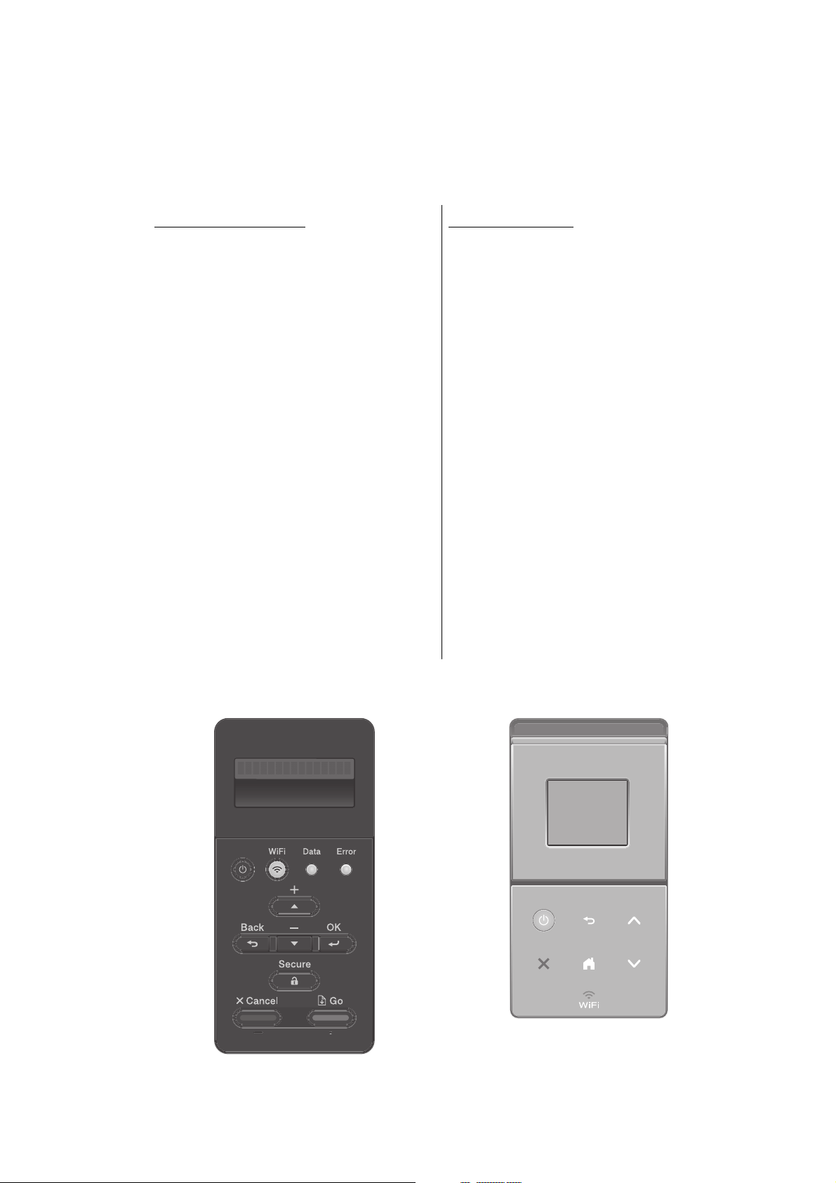
Non touch panel models
(1) Press the [OK] key and then the [Go] key while the machine is in the ready state. Then,
press the [▲] key four times to enter the maintenance mode.
Note:
• To enter the maintenance mode, press the [Go] key in two seconds after pressing the
[OK] key. Similarly, press the [▲] key in two seconds after pressing the [Go] key.
(2) "■■ MAINTENANCE ■■■" is displayed on the LCD to indicate that the machine entered
the initial state of maintenance mode. The machine is ready to accept entry via keys.
(3) To select any of the maintenance mode functions shown in the “1.2 List of Maintenance
Mode Functions”, press the [▲] or [▼] key. Check that the desired maintenance mode is
displayed on the LCD, and press the [OK] key.
5-1
Confidential
Page 2
Touch panel models
<1> <2> <3>
To <3> To <1>
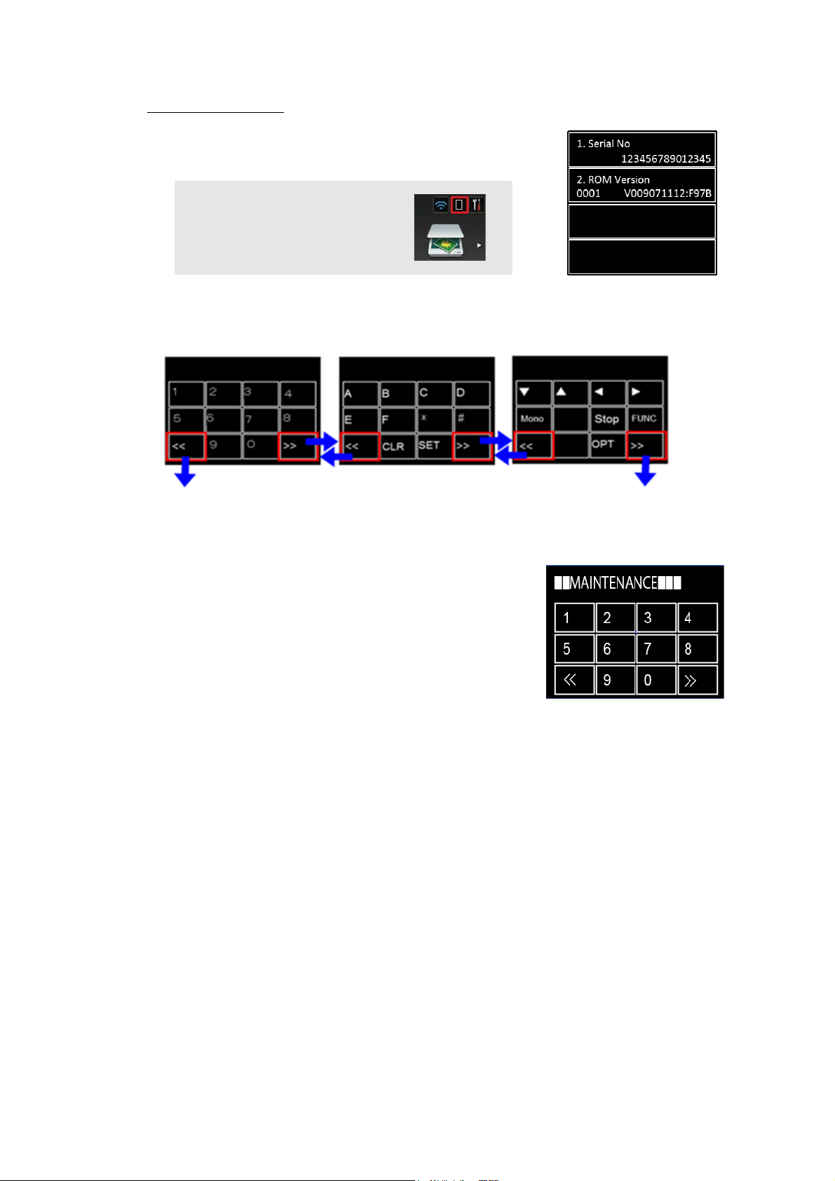
(1) Press and hold the [Home] key for approximately five
seconds while the machine is in the ready state. The
display shown on the right appears on the LCD.
Memo:
• If you can not find the [Home]
key, press the [Toner] key to light
the [Home] key.
(2) Press the blank field at the bottom on the LCD. The display below appears on the LCD.
Input keys can be changed by pressing the [<<] or [>>] key (refer to the figure below).
Fig. 5-1
(3) Press the [*], [2], [8], [6], and [4] keys in this order. The
display shown on the right appears on the LCD, and the
machine enters into maintenance mode.
(4) To select any of the maintenance mode functions shown
in the “1.2 List of Maintenance Mode Functions”, use the
keypad to enter the maintenance mode function code to
be executed.
5-2
Confidential
Page 3
1.1.2 Method of entering end-user accessible maintenance mode
The maintenance mode functions should only be accessed by service personnel. However,
end users are allowed to use some of these functions under the guidance of service
personnel over the phone. End users can only use the functions shaded in the table “1.2 List
of Maintenance Mode Functions” (function code: 09, 12, 25, 28, 45, 61, 77, 80, 82, 91).
<Operating Procedure>
Non touch panel models
(1) Press the [OK], [Go], and [OK] keys in this order while the machine is in the ready state.
"0" is displayed on the LCD.
(2) Press the [▲] or [▼] key several times until the desired maintenance mode function is
displayed on the LCD. Check that the desired maintenance mode is displayed on the
LCD, and press the [OK] key.
(3) Each time the selected maintenance mode function is completed, the machine returns to
the ready state automatically. For function codes 12, 25, 28, 45, 80, and 82, pressing the
[X] key returns the machine to the ready state.
Touch panel models
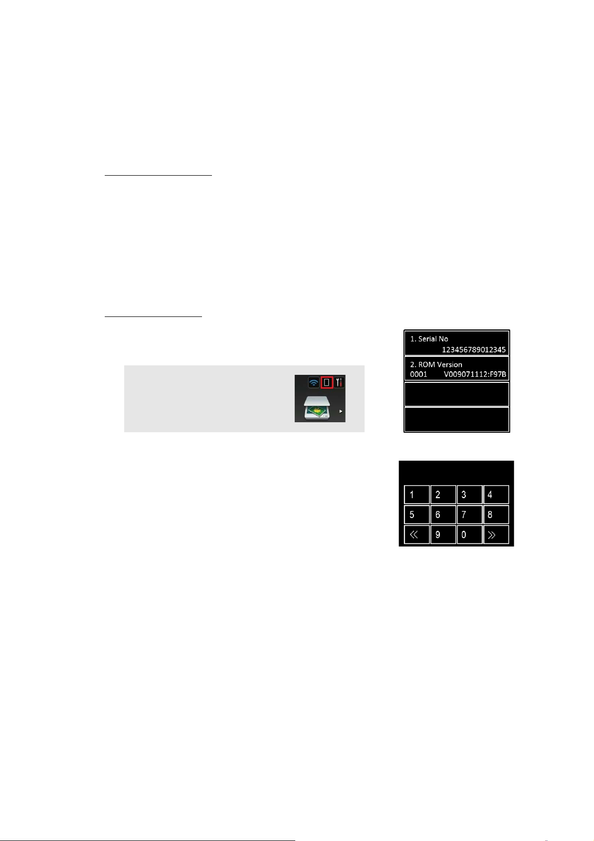
(1) Press and hold the [Home] key for approximately five
seconds while the machine is in the ready state. The
display shown on the right appears on the LCD.
Memo:
• If you can not find the [Home]
key, press the [Toner] key to light
the [Home] key.
(2) Press the blank field at the bottom on the LCD.
The display shown on the right appears on the LCD.
(For functions of the [<<] or [>>] key, refer to the Fig. 5-1)
(3) Press the [*], [0], and [#] keys on the LCD in this order. The
machine enters into ready state to accept function code
entry, so press the function code you want to execute.
(4) Each time the selected maintenance mode function is
completed, the machine returns to the ready state
automatically.
5-3
Confidential
Page 4
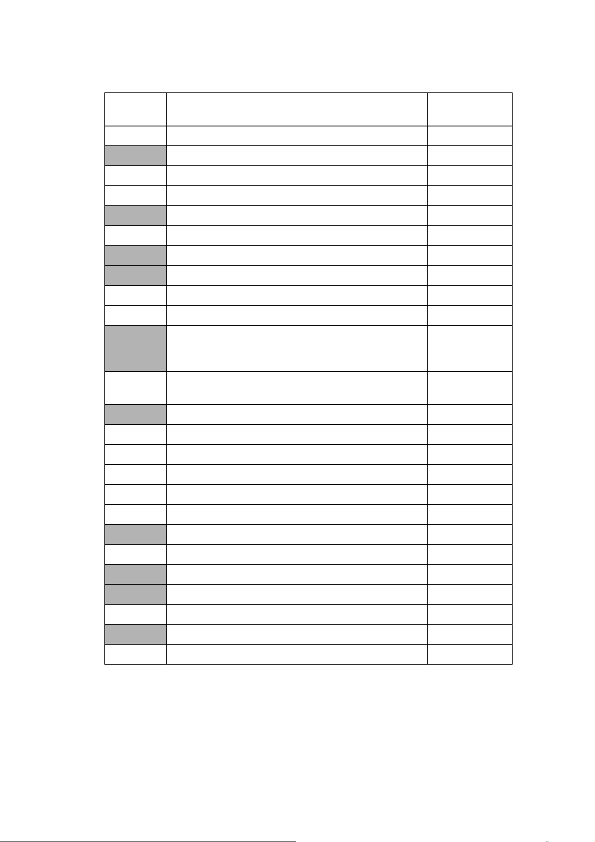
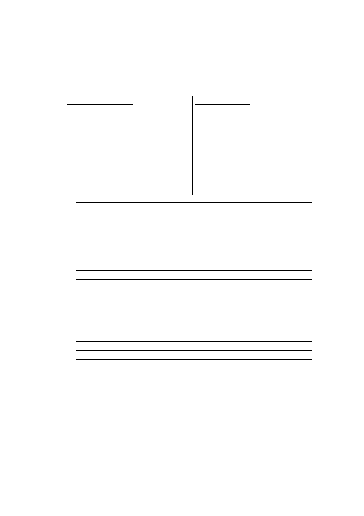
1.2 List of Maintenance Mode Functions
Function
code
01 Initialize EEPROM parameters 1.3.1
09 Print quality test pattern 1.3.2
10 Set worker switches (WSW) 1.3.3
11 Print worker switch (WSW) setting data 1.3.3
12 Check LCD operation 1.3.4
13 Check control panel key operation 1.3.5
25 Display software version 1.3.6
28 Change setting for OnePushDemo function 1.3.7
32 Check sensor operation 1.3.8
33 Display LAN connection status 1.3.9
Change USB No. return value / Adjust left-end print
45
46
position / Adjust upper-end print position / Set HEXDUMP
mode
Adjust printable range for each speed level
(Full speed / Half speed for thick paper / Quiet Mode)
Function Refer to:
1.3.10
1.3.11
61 Adjust touch panel 1.3.12
67 Continuous print test 1.3.13
69 Print frame pattern (single-side printing) 1.3.14
70 Print frame pattern (duplex printing) 1.3.15
71 Print test pattern 1.3.16
74 Configure for country/region and model 1.3.17
77 Print maintenance information 1.3.18
78 Check main fan operation 1.3.19
80 Display machine log information 1.3.20
82 Display machine error code 1.3.21
88 Reset counters for consumable parts 1.3.22
91 Initialize EEPROM parameters 1.3.1
99 Quit maintenance mode 1.3.23
* The maintenance mode functions shaded in the table can be used by end users.
5-4
Confidential
Page 5
1.3 Details of Maintenance Mode Functions
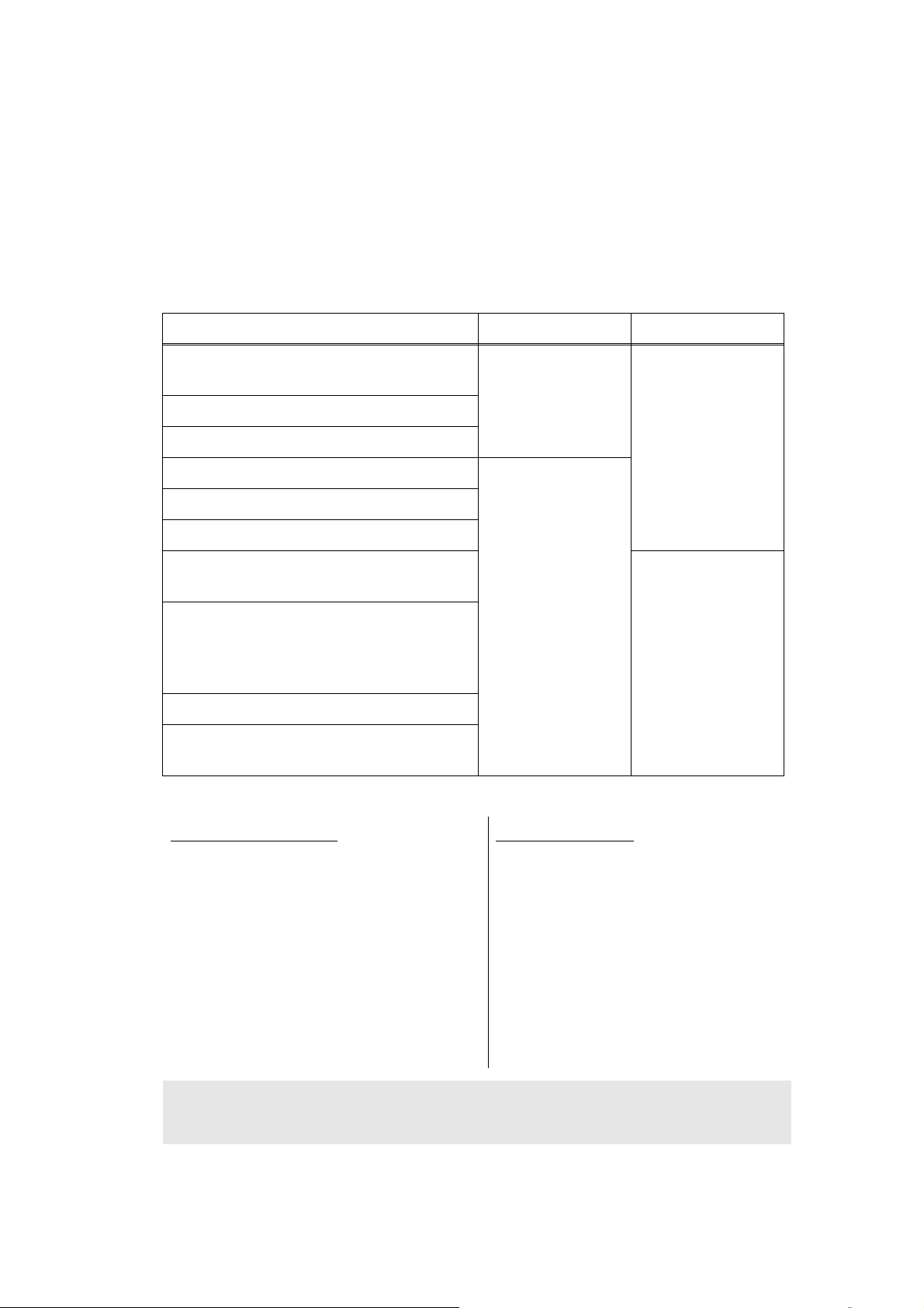
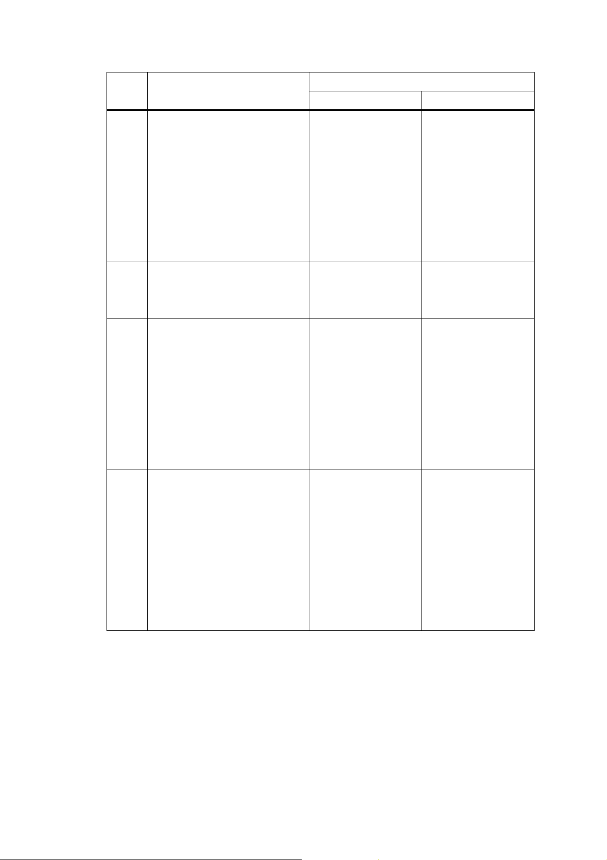
1.3.1 Initialize EEPROM parameters (function code: 01, 91)
<Function>
This function is used to initialize the setting values for operation parameters, user switches,
and worker switches (WSW) registered in the EEPROM.
Entering function code 01 initializes most EEPROM areas. Entering function code 91
initializes only the specified areas as shown in the table below.
Data item 01 91
Printer switch
(Counter information)
Error history
Mac Address (Ethernet Address)
Password for control panel operation lock Areas to be
Secure function lock
Worker switches
User switches (items initialized when
"Factory Reset" is executed)
Function settings except user switches
(settings not subject to "Factory Reset")
- Language
- Interface
LAN setting
PCL core area
(Emulation setting values)
Areas not to be
initialized
initialized
<Operating Procedure>
Areas not to be
initialized
Areas to be
initialized
Non touch panel models
(1) Press the [▲] or [▼] key in the initial
state of maintenance mode to display
"Maintenance 01" (or "Maintenance
91" as required) on the LCD, and
press the [OK] key.
"PARAMETER INIT" is displayed on
the LCD.
(2) When initializing parameters is
completed, the machine returns to the
initial state of maintenance mode.
Note:
• Function code 01 is for service personnel. Function code 91 is for user support.
Touch panel models
(1) Press the [0], and then the [1] key (or
press the [9] and then the [1] key as
required) in the initial state of
maintenance mode. "PARAMETER
INIT" is displayed on the LCD.
(2) When initializing parameters is
completed, the machine returns to the
initial state of maintenance mode.
5-5
Confidential
Page 6
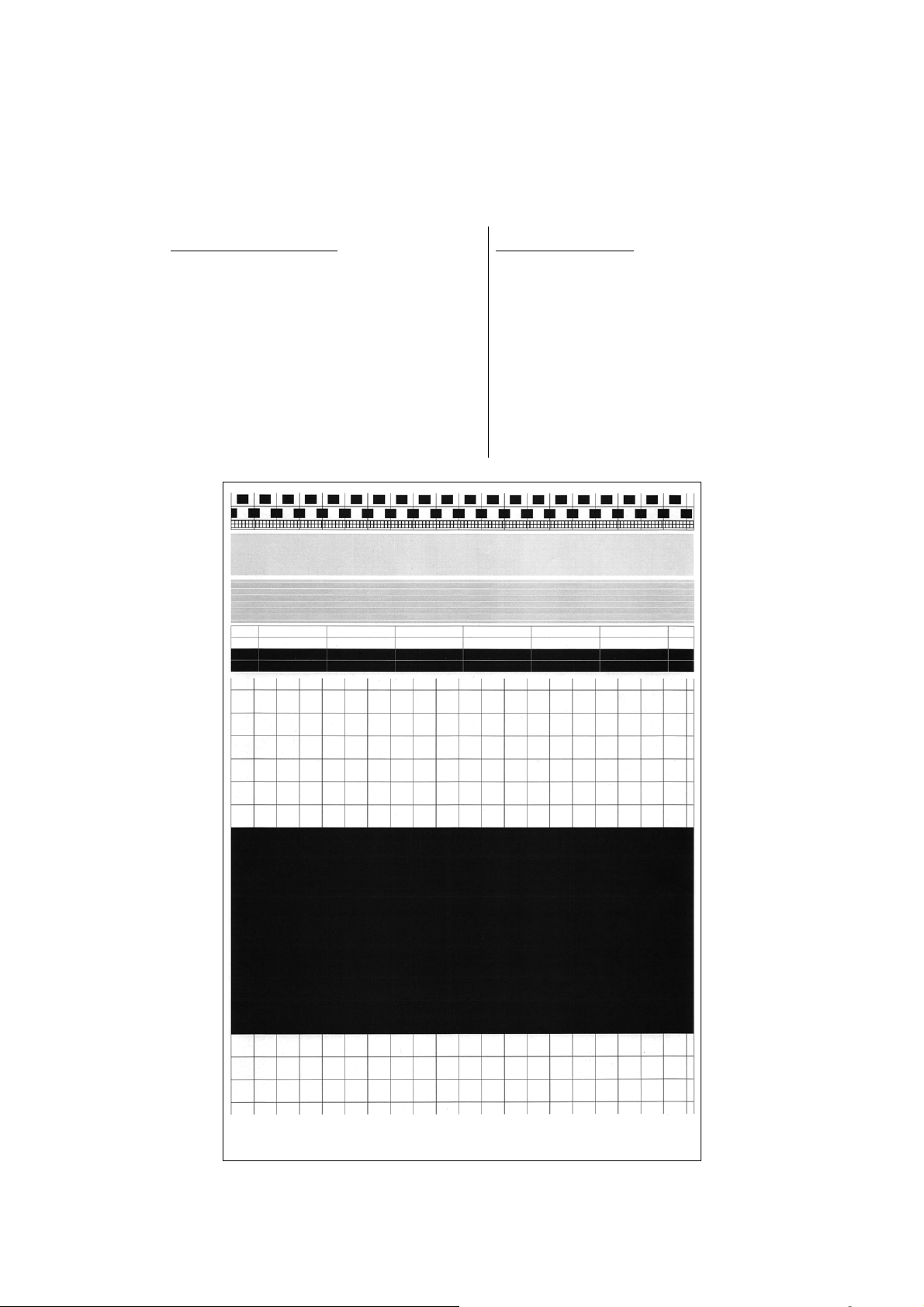
1.3.2 Print quality test pattern (function code: 09)
<Function>
This function is used to print test patterns to check any missing image and print quality.
<Operating Procedure>
Non touch panel models
(1) Press the [▲] or [▼] key in the initial
state of maintenance mode to display
"MAINTENANCE 09" on the LCD, and
press the [OK] key. It starts printing
the print quality test pattern (refer to
the figure below).
(2) When printing is completed, the
machine returns to the initial state of
maintenance mode.
Touch panel models
(1) Press the [0], and then the [9] key in the
initial state of maintenance mode.
"MAINTENANCE 09" is displayed on
the LCD, and the machine starts
printing the print quality test pattern
(refer to the figure below).
(2) When printing is completed, the
machine returns to the initial state of
maintenance mode.
Fig. 5-2
5-6
Confidential
Page 7
1.3.3 Set worker switches (WSW) and print worker switch setting data (function code: 10, 11)
[1] Set worker switches (function code: 10)
<Function>
The worker switches shown in the table below can be used to set the function to satisfy
various requirements. These switch settings can be changed using the keys on the control
panel.
The worker switches are factory set to conform to the laws and regulations of the country the
machine is shipped to. Do not change these settings unless necessary.
WSW No. Function
WSW17 selector 5
WSW47 selector 8 Change USB High/Full Speed
WSW56 selector 1
WSW56 selector 6 Change coverage type display
Change time display method
(American: MM/DD/YY or European: DD/MM/YY)
Change ON/OFF setting for models without PS emulation
function.
WSW56 selector 7
WSW59 selector 1 Change ON/OFF setting for USB serial number sending
WSW63 selector 1-2 Change printing speed
WSW63 selector 3
WSW63 selector 4-7 Demo printing type
WSW63 selector 8 Change ON/OFF setting for Israeli font support
WSW64 selector 1-6 Language setting
WSW64 selector 7-8 Default paper size
WSW65 selector 1-2 Default media type
WSW65 selector 3 Change ON/OFF setting for Bond Paper support
WSW65 selector 4 Change ON/OFF setting for Postcard support
WSW65 selector 6 Change ON/OFF setting for Label support
WSW78 selector 1
WSW81 selector 1
Change ON/OFF setting for models without PCL emulation
function.
Change time display method
(Japanese: YY/MM/DD or others)
Change continue/stop setting for printing when the drum
reach the life limit.
Change ON/OFF setting for models with PS emulation
function.
WSW81 selector 2
* Refer to the separate manual for details of worker switches.
Change ON/OFF setting for models with PCL emulation
function.
5-7
Confidential
Page 8

<Operating Procedure>
WSWXX = 0 0 0 0 0 0 0 0
Selector No. 1 Selector No. 8
WSWXX = 0 0 0 0 0 0 0 0
Selector No. 1 Selector No. 8
Non touch panel models
(1) Press the [▲] or [▼] key in the initial
state of maintenance mode to display
"MAINTENANCE 10" on the LCD.
(2) Press the [OK] key. "WSW00" is
displayed on the LCD, indicating that
the machine is ready for worker switch
number entry.
(3) Press the [▲] or [▼] key to display the
worker switch number for which you
want to change the setting on the
LCD.
(4) Press the [OK] key. The following
message is displayed on the LCD,
and selector No.1 flashes.
(5) Pressing the [▲] key enters "1", and
pressing the [▼] key enters "0". Press
either to enter desired number to
Selector No.1. The next digit starts
flashing.
(6) Keep entering numbers to Selector
No.8 using the [▲] or [▼] key as
described in the procedure (5).
(7) Press the [OK] key. The new selector
setting value is stored in the
EEPROM, and the LCD returns to the
ready state for worker switch number
entry ([WSW00]).
(8) When all switch setting is completed,
press the [OK] or [X] key to return the
machine to the initial state of
maintenance mode.
Touch panel models
(1) Press the [1], and then the [0] key in the
initial state of maintenance mode.
"WSW00" is displayed on the LCD.
(2) Enter the worker switch number that
you want to change the setting.
The following display appears on the
LCD.
(3) Press the [ ] or [ ] key to move the
cursor to the desired selector, and
change the setting by pressing the [1]
or [0] key.
(4) When changing the setting is
completed, press the [SET] key. The
new selector setting value is stored in
the EEPROM, and the LCD returns to
the ready state for worker switch
number entry ("WSW00").
(5) When all switch setting is completed,
press the [X] key to return the
machine to the initial state of
maintenance mode.
Note:
• To cancel operation and return to the initial state of maintenance mode, press the [X] key.
• If there is no entry for one minute or longer on 2-digit worker switch number selection after
the first digit was entered, the machine returns to the initial state of maintenance mode
automatically.
5-8
Confidential
Page 9
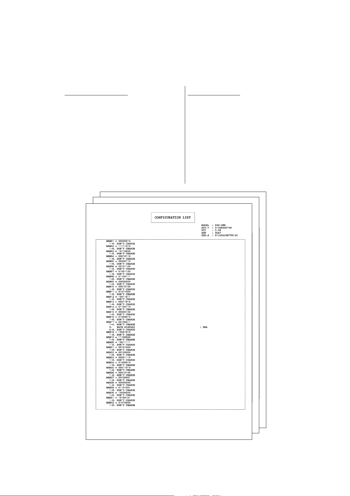
[2] Print worker switch (WSW) setting data (function code: 11)
<Function>
This function is used to print the worker switch settings and details.
<Operating Procedure>
Non touch panel models
(1) Press the [▲] or [▼] key in the initial
state of maintenance mode to display
"MAINTENANCE 11" on the LCD, and
press the [OK] key.
(2) "PRINTING" is displayed on the LCD,
and printing the CONFIGURATION
LIST (refer to the figure below) starts.
(3) When printing is completed, the
machine returns to the initial state of
maintenance mode.
Touch panel models
(1) Press the [1] key twice in the initial
state of maintenance mode.
"PRINTING" is displayed on the LCD,
and printing the CONFIGURATION
LIST (refer to the figure below) starts.
(2) When printing is completed, the
machine returns to the initial state of
maintenance mode.
Fig. 5-3
5-9
Confidential
Page 10
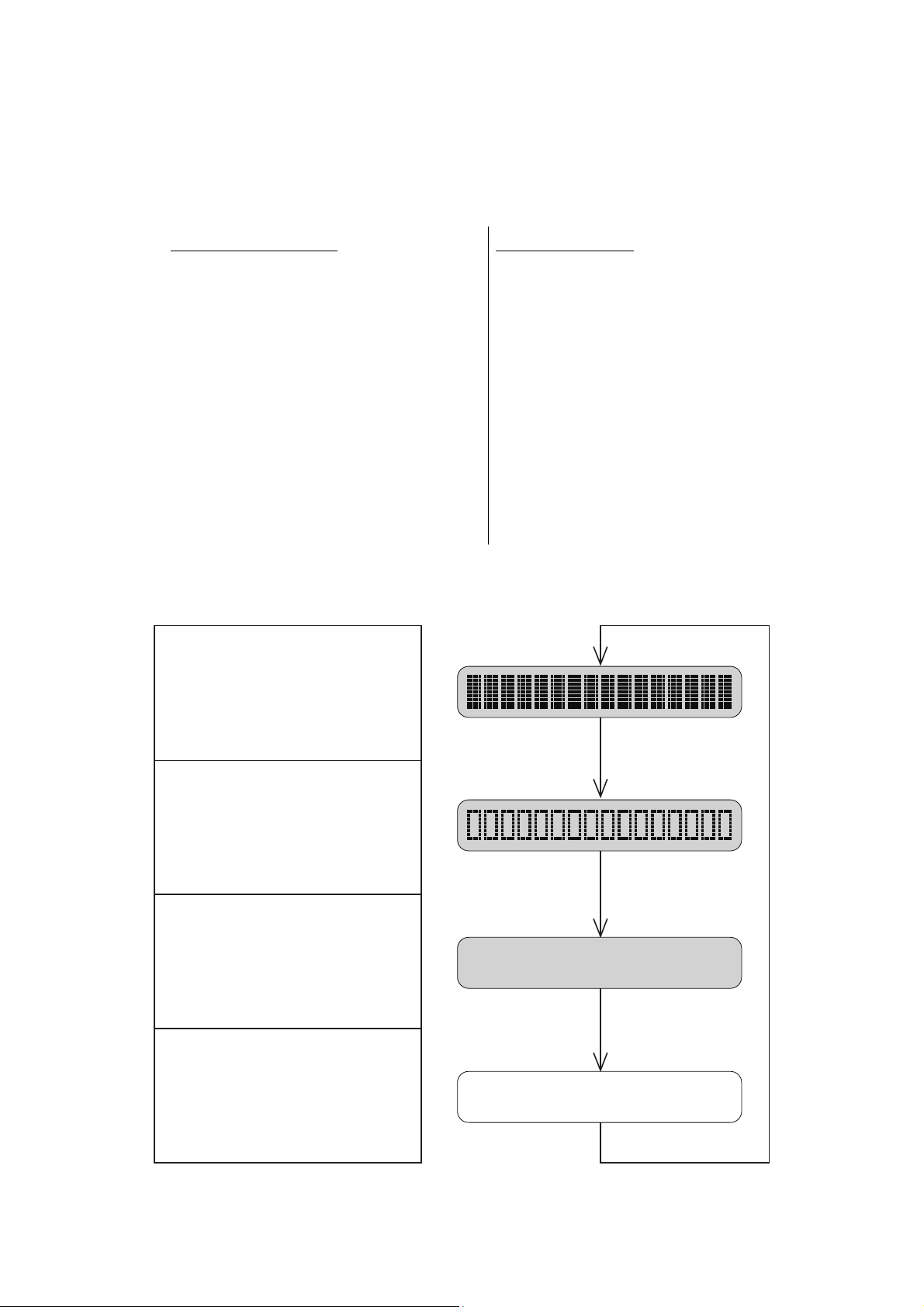
1.3.4 Check LCD operation (function code: 12)
<Function>
This function is used to check that the LCD on the control panel is operating normally.
<Operating Procedure>
Non touch panel models
(1) Press the [▲] or [▼] key in the initial
state of maintenance mode to display
"MAINTENANCE 12" on the LCD, and
press the [OK] key.
(2) Each press of the [Go] key cycles
through the displays as shown in the
figure below.
(3) When you press the [X] key, the
machine returns to the initial state of
maintenance mode, regardless of the
display status.
■ LCD
<Non touch panel models>
<Display 1>
Back light: OFF
LCD: Displays all dots
Touch panel models
(1) Press the [1], and then the [2] key in
the initial state of maintenance mode.
(2) Each press of the [
through the displays as shown in Fig.
5-5. Also, pressing the [
the LCD display to the previous state.
Pressing the [
display returns the display to Display
1.
(3) When you press the [X] key, the
machine returns to the initial state of
maintenance mode, regardless of the
display status.
Display 1
˄
] key cycles
˅
˄
] key at the end of
] key returns
<Display 2>
Back light: OFF
LCD: Displays 16 frames
in a line
<Display 3>
Back light: OFF
LCD: Displays no dots
<Display 4>
Back light: ON (white)
LCD: Hides all dots
Display 2
Display 3
Display 4
Fig. 5-4
5-10
Confidential
Page 11
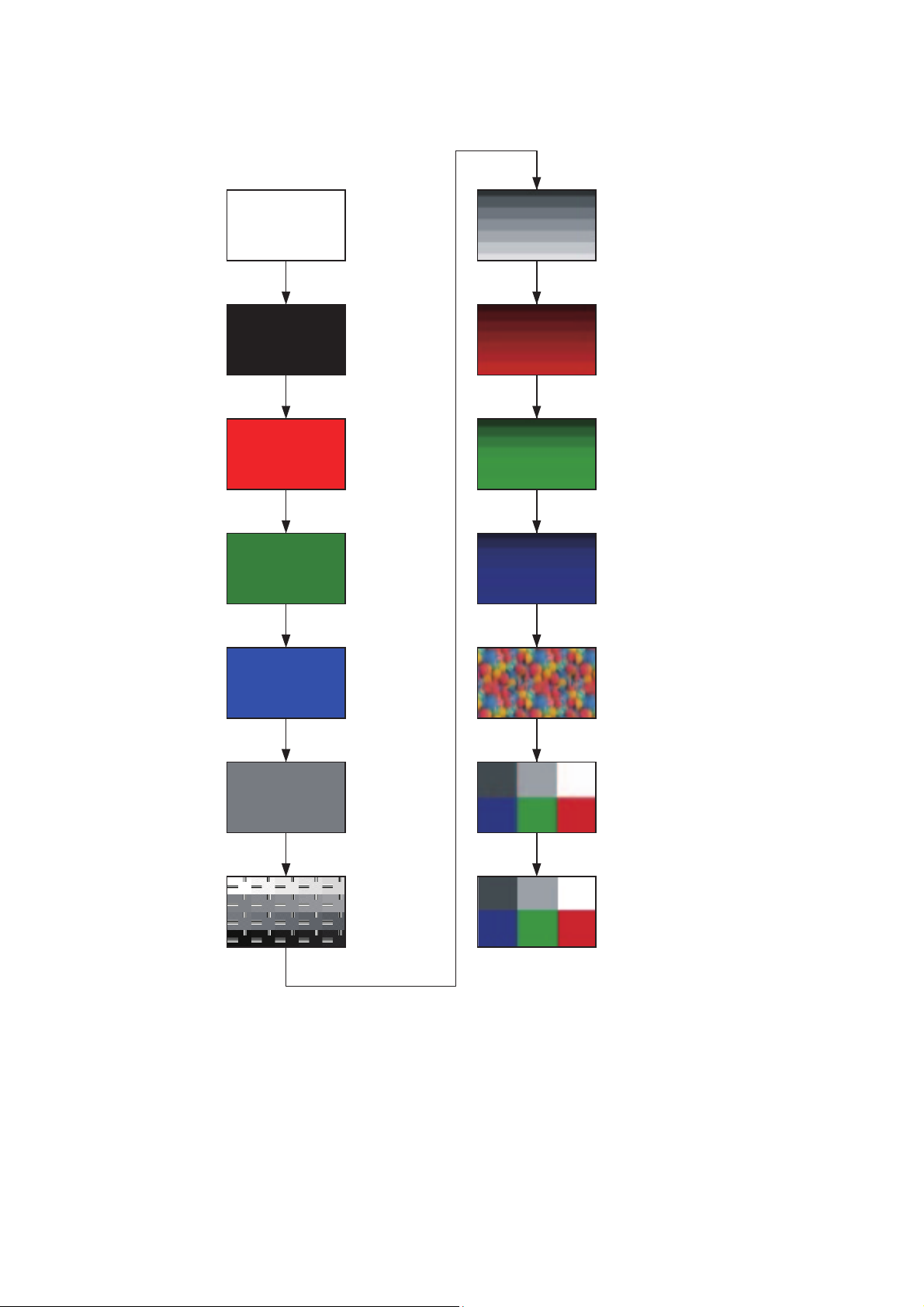
<Touch panel models>
<Display 1>
<Display 2>
<Display 3>
<Display 4>
<Display 5>
<Display 6>
<Display 7>
<Display 8>
<Display 9>
<Display 10>
<Display 11>
<Display 12>
<Display 13>
<Display 14>
Fig. 5-5
5-11
Confidential
Page 12
1.3.5 Check control panel key operation (function code: 13)
123
45 6
<Function>
This function is used to check that keys on the control panel are operating normally.
<Operating Procedure>
Non touch panel models
(1) Press the [▲] or [▼] key in the initial
state of maintenance mode to display
"MAINTENANCE 13" on the LCD, and
press the [OK] key. "00" is displayed
on the LCD.
(2) Press the keys on the control panel
according to the numbers provided in
the figure below. Each time the key is
pressed, the corresponding figure is
displayed on the LCD in decimal
notation. Check that the number and
the key name displayed on the LCD
matches the number assigned to the
key that has been pressed. If the keys
are pressed in the incorrect order,
"INVALID OPERATE" is displayed on
the LCD. Press the [X] key and try
again with the correct key.
(3) When the key operation is normal, the
machine returns to the initial state of
maintenance mode when the last key
is pressed.
To cancel operation and return to the
initial state of maintenance mode,
press the [X] key.
Touch panel models
(1) Press the [1], and then the [3] key in
the initial state of maintenance mode.
"00" is displayed on the LCD.
(2) Press the keys on the control panel
according to the numbers provided in
the figure below. Each time the key is
pressed, the corresponding figure is
displayed on the LCD in decimal
notation. Check that the number
displayed on the LCD matches the
number assigned to the key that has
been pressed. If the keys are pressed
in the incorrect order, "INVALID
OPERATE" is displayed on the LCD.
Press the [X] key and try again with
the correct key.
(3) When the key operation is normal, the
machine returns to the initial state of
maintenance mode when the last key
is pressed. To cancel operation and
return to the initial state of
maintenance mode, press the [X] key.
■ Order of pressing keys
<Non touch panel models>
12
3
456
7
89
Fig. 5-6
<Touch panel models>
Fig. 5-7
5-12
Confidential
Page 13
1.3.6 Display software version (function code: 25)
<Function>
This function is used to check the version information of the firmwares and programs, or
check sum information.
<Operating Procedure>
Non touch panel models
(1) Press the [▲] or [▼] key in the initial
state of maintenance mode to display
"MAINTENANCE 25" on the LCD, and
press the [OK] key. "MAIN:Ver*.** (#)"
is displayed on the LCD.
(2) Pressing the [Go], [▲] or [▼] key
changes the display item as shown in
the table below.
(3) Press the [X] key, and the machine
returns to the initial state of
Touch panel models
(1) Press the [2], and then the [5] key in
the initial state of maintenance mode.
"MAIN:Ver*.** (#)" is displayed on the
LCD.
˄
(2) Pressing the [▲], [
], or [Mono] key
changes the display to the next item.
(3) When you press the [X] key, this
operation is finished and the machine
returns to the initial state of
maintenance mode.
maintenance mode.
LCD Description
MAIN: Ver1.00 (A)
*1
Main firmware version information
((A): Revision information)
SUB1 : Ver1.00 (P)
*1
Sub firmware version information
((P): Identifier for PCL/PS)
*2
ENG: Ver.1.00 Do not refer to this item because it has nothing to do with DL.
NET : Ver1.00 Network program version information
MX :Ver1.00 MX firmware version information
TT :Ver1.00 TT firmware version information
LT1 :Ver1.00 LT1 firmware version information
LT2 :Ver1.00 LT2 firmware version information
LT3 :Ver1.00 LT3 firmware version information
*1
B0608071049:5708
U0612271600:7B0A
D----------:----
*4
F0612312359:1234
P0612271602:BD40
ROM Check Sum Check sum self-diagnosis function
*1
How to display the check sum information
Boot program creation date
*1
Main firmware creation date
Demo firmware data creation date
*5
Font firmware creation date
*1
Sub firmware (PCL/PS) creation date
*3
You can check the check sum information by pressing the [OK] key while each version
is displayed. When the [OK] key is pressed again, the LCD returns to the version
display.
*2
(P) indicates that the firmware supports PCL/PS.
*3
There are two types of check sum information that can be checked with this function.
This function checks if the two types of check sum information match each other.
When the [OK] key is pressed while "ROM Check Sum" is displayed, check is
automatically conducted for each ROM of each software part. When the check sum
matches, "OK" is displayed on the LCD. When all ROMs result in OK, "ROM Check
Sum OK" is displayed at the end, and the operation is finished. When the check sum
of any ROM does not match, "NG" is displayed, and the display stops.
*4
This is displayed on the LCD even no firmware is installed.
*5
Displayed only for font firmware support model.
5-13
Confidential
Page 14

1.3.7 Change OnePushDemo function setting (function code: 28)
<Function>
This function is used to implement Demo printing by pressing a certain key, and is mainly
used for sales promotion at dealers. This function is disabled once printing is performed from
the computer. Change the setting to enable the function again.
OnePushDemo = ON(Enabled) / OFF(Disabled).
The setting currently selected is marked "*".
<Operating Procedure>
Non touch panel models
(1) Press the [▲] or [▼] key in the initial
state of maintenance mode to display
"MAINTENANCE 28" on the LCD, and
press the [OK] key.
"OnePushDemo=ON" is displayed on
the LCD.
(2) Press the [▲] or [▼] key to display
"OnePushDemo=ON" when enabling
this function or "OnePushDemo=OFF"
when disabling this function.
(3) Press the [OK] key. The setting
currently displayed is saved, and the
machine returns to the initial state of
maintenance mode.
Note:
• To cancel operation and return to the initial state of maintenance mode, press the [X] key.
• Once the OnePushDemo function is enabled, this will not be disabled even when
printing is performed from the computer as long as the power switch is not turned OFF.
However, if the power switch is turned OFF and then ON again after the OnePushDemo
function was enabled, this function will be disabled when printing is performed from the
computer.
Touch panel models
(1) Press the [2], and then the [8] key in
the initial state of maintenance mode.
"OnePushDemo=ON" is displayed on
the LCD.
(2) Press the [
"OnePushDemo=ON" when enabling
this function or "OnePushDemo=OFF"
when disabling this function.
(3) Press the [SET] or [Mono] key. The
setting currently displayed is saved,
and the machine returns to the initial
state of maintenance mode.
˄
] or [˅] key to display
5-14
Confidential
Page 15

1.3.8 Check sensor operation (function code: 32)
Non touch panel models
(1) Press the [▲] or [▼] key in the initial
state of maintenance mode to display
"MAINTENANCE 32" on the LCD, and
press the [OK] key. "TNNT--C2P2****" is
displayed on the LCD. The machine
makes buzzing sound continuously.
Information related to the LT, TT, and MX
are not displayed on the LCD when
those are not connected.
(2) Pressing the [Go] key changes the
display to the next item.
(3) Change the conditions subject to sensor
detection shown below and check that
the display on the LCD changes
depending on the sensor status. For
example, feed the paper through the
registration front/rear sensor, open the
front cover or back cover, remove the
toner cartridge, or create paper jam at
the exit.
(4) When you press the [X] key, this
operation is finished and the machine
returns to the initial state of maintenance
mode.
Touch panel models
(1) Press the [3], and then the [2] key in the
initial state of maintenance mode. Either
of the following examples is displayed
on the LCD
e.g. TNNTSTC2P2**TT**
e.g. TNNTST----MCTT
The machine makes buzzing sound
continuously.
Information related to the LT, TT, and MX
are not displayed on the LCD when
those are not connected.
(2) Pressing the [Mono] key changes the
display to the next item.
(3) Change the conditions subject to sensor
detection shown below and check that
the display on the LCD changes
depending on the sensor status. For
example, feed the paper through the
registration front/rear sensor, open the
front cover or back cover, remove the
toner cartridge, or create paper jam at
the exit.
(4) When you press the [STOP] key, this
operation is finished and the machine
returns to the initial state of maintenance
mode.
Note:
• Press the [OK] key to stop the
buzzing sound.
Note:
• Press the [SET] key to stop the
buzzing sound.
<Function>
This function is used to check whether the sensors, solenoids, and clutches are operating normally.
<Operating Procedure>
<Sensor check>
The table below summarizes the displays on the LCD, sensor names and detection status.
LCD Sensor name
TN Toner amount detection sensor Beam obstructed Beam not obstructed
NT New toner sensor Sensor not pressed Sensor pressed
ST Output tray stack sensor
C2 T2LT Paper feed sensor Paper tray 2 closed Paper tray 2 open
P2 T2LT paper empty sensor No paper Paper set
MC MX back cover sensor MX back cover closed MX back cover open
TT TT connection sensor TT connected TT not connected
5-15
With display No display
Ejected paper not yet full
Detection status
Ejected paper full
Confidential
Page 16
LCD Sensor name
Detection status
With display No display
C1 T1 paper feed sensor Paper tray 1 closed Paper tray 1 open
P1 T1 paper empty sensor No paper Paper set
MP MP paper empty sensor No paper Paper set
CV Front cover sensor Front cover closed Front cover open
RC Back cover/duplex tray sensor Back cover closed Back cover open
PO Eject sensor No paper Paper set
RM Registration front sensor No paper Paper set
RA Registration rear sensor No paper Paper set
MACxx Internal temperature sensor
OTxx External temperature sensor
XX
XX
C
C
NG
NG
OHxx External humidity sensor XX% NG
S1
S2
S3
S4
MX 1bin stack sensor Ejected paper not yet full
MX 2bin stack sensor Ejected paper not yet full
MX 3bin stack sensor Ejected paper not yet full
MX 4bin stack sensor Ejected paper not yet full
B2 MX 2bin sensor
B4 MX 4bin sensor
MX 2bin paper set MX 2bin no paper
MX 4bin paper set MX 4bin no paper
Ejected paper full
Ejected paper full
Ejected paper full
Ejected paper full
ML MX JAM lower sensor No paper Paper set
MU MX JAM upper sensor No paper Paper set
C2 T2LT paper feed sensor
Paper tray 2 closed Paper tray 2 open
(When LT is in use)
P2 T2LT paper empty sensor
No paper Paper set
(When LT is in use)
C3 T3LT paper feed sensor
Paper tray 3 closed Paper tray 3 open
(When LT is in use)
P3 T3LT paper empty sensor
(When LT is in use)
C4 T4LT paper feed sensor
(When LT is in use)
No paper Paper set
Paper tray 4 closed Paper tray 4 open
5-16
Confidential
Page 17
LCD Sensor name
Detection status
With display No display
E2 T2TT paper feed sensor TT paper tray 2 closed
and No paper
TT paper tray 2 open
and Paper set
D2 T2TT paper empty sensor No paper Paper set
E3 T3TT paper feed sensor TT paper tray 3 closed
and No paper
TT paper tray 3 open
and Paper set
D3 T3TT paper empty sensor No paper Paper set
E4 T4TT paper feed sensor TT paper tray 4 closed
and No paper
TT paper tray 4 open
and Paper set
D4 T4TT paper empty sensor No paper Paper set
E5 T5TT paper feed sensor TT paper tray 5 closed
and No paper
TT paper tray 5 open
and Paper set
D5 T5TT paper empty sensor No paper Paper set
J2 T2 JAM sensor No paper Paper set
J3 T3 JAM sensor No paper Paper set
J4 T4 JAM sensor No paper Paper set
J5 T5 JAM sensor No paper Paper set
AL TT balance sensor L With attachment No attachment
AR TT balance sensor R With attachment No attachment
<Solenoid and clutch check>
Check the corresponding solenoid and clutch by activating the sensor below.
Both solenoid and clutch can not detect error or fault. They only check if they are functioning.
Sensor operation Solenoid/clutch operation
Change the status of the T1 paper feed sensor from
Paper tray 1 open to Paper tray 1 closed.
Change the status of the T2LT paper feed sensor from
Paper tray 2 open to Paper tray 2 closed.
Change the status of the T2LT paper empty sensor from
No paper to Paper set.
Change the status of the T3LT paper feed sensor from
Paper tray 3 open to Paper tray 3 closed.
Change the status of the T3LT paper empty sensor from
No paper to Paper set.
Change the status of the T4LT paper feed sensor from
Paper tray 4 open to Paper tray 4 closed.
The T1 pickup clutch remains ON
for the specified time.
The T2LT pickup clutch remains ON
for the specified time.
The T2LT release clutch remains ON
for the specified time.
The T3LT pickup clutch remains ON
for the specified time.
The T3LT release clutch remains
ON for the specified time.
The T4LT pickup clutch remains ON
for the specified time.
Change the status of the T4LT paper empty sensor from
No paper to Paper set.
Change the status of the MP paper empty sensor from
No paper to Paper set.
5-17
The T4LT release clutch remains
ON for the specified time.
The MP solenoid remains ON for
the specified time.
Confidential
Page 18

Sensor operation Solenoid/clutch operation
Change the status of the registration rear sensor from
No paper to Paper set.
Change the status of the new toner sensor from
Not pressed to Pressed.
Change the status of the MX 1bin stack sensor from
Not full to Full.
Change the status of the MX 2bin stack sensor from
Not full to Full.
Change the status of the MX 3bin stack sensor from
Not full to Full.
Change the status of the MX 1bin stack sensor from
Full to Not full.
Change the status of the MX 2bin stack sensor from
Full to Not full.
Change the status of the MX 3bin stack sensor from
Full to Not full.
The registration clutch remains ON
for the specified time.
The develop clutch remains ON for the
specified time.
Erase Lamp is ON (keep the develop
clutch ON until the new toner sensor
gets pressed)
MX solenoid is moved to MX 1bin
side.
MX solenoid is moved to MX 2bin
side.
MX solenoid is moved to MX 3bin
side.
MX solenoid is moved to the side
which does not eject paper to the
MX 1bin.
MX solenoid is moved to the side
which does not eject paper to the
MX 2bin.
MX solenoid is moved to the side
which does not eject paper to the
MX 3bin.
Change the status of the
TT paper tray 2 open to TT paper tray 2 closed.
Change the status of the
TT paper tray 3 open to TT paper tray 3 closed.
Change the status of the
TT paper tray 4 open to TT paper tray 4 closed.
Change the status of the
TT paper tray 5 open to TT paper tray 5 closed.
Change the status of the T3TT paper empty sensor from
No paper to Paper set.
Change the status of the T4TT paper empty sensor from
No paper to Paper set.
Change the status of the T5TT paper empty sensor from
No paper to Paper set.
T2TT paper feed sensor from
T3TT paper feed sensor from
T4TT paper feed sensor from
T5TT paper feed sensor from
The T2TT pickup clutch remains
ON for the specified time.
The T3TT pickup clutch remains
ON for the specified time.
The T4TT pickup clutch remains
ON for the specified time.
The T5TT pickup clutch remains ON
for the specified time.
The T3TT release clutch remains
ON for the specified time.
The T4TT release clutch remains
ON for the specified time.
The T5TT release clutch remains
ON for the specified time.
Note:
• LCD display changes by activating the sensors above. However, it does not affect to the
operation of the solenoid and clutch. If the sensors to operate the solenoid and clutch are
faulty, they are inoperable.
5-18
Confidential
Page 19

Location of sensors
Toner amount detection sensor PCB (light reception)
Eject sensor
Eject stack sensor
Registration front/rear sensor
MP paper empty
sensor
T1 paper empty sensor
LT paper feed sensor
LT paper empty sensor
Front cover sensor
T1 paper feed sensor
Internal temperature sensor
Toner amount detection sensor PCB
(light emission)
Back cover/duplex
tray sensor
New toner sensor
Fig. 5-8
5-19
Confidential
Page 20

Fig. 5-9
MX 2bin sensor
MX 1bin stack sensor
MX 4bin sensor
MX 2bin stack sensor
MX 3bin stack sensor
MX 4bin stack sensor
MX JAM lower sensor
MX JAM upper sensor
MX back cover sensor
TT jam sensor PCB ASSY
TT paper feed sensor
PCB ASSY
TT balance sensor L
TT jam sensor
PCB ASSY
TT jam sensor
PCB ASSY
TT paper feed sensor
PCB ASSY
TT paper feed sensor
PCB ASSY
TT paper empty
sensor PCB ASSY
TT paper feed sensor
PCB ASSY
TT paper empty
sensor PCB ASSY
TT paper empty
sensor PCB ASSY
TT jam sensor PCB ASSY
TT balance sensor R
TT paper empty sensor PCB ASSY
Fig. 5-10
5-20
Confidential
Page 21

1.3.9 Display LAN connection status (function code: 33)
<Function>
This function is used to check the connection status of the wired LAN.
<Operating Procedure>
Non touch panel models
(1) Press the [▲] or [▼] key in the initial
state of maintenance mode to display
"MAINTENANCE 33" on the LCD, and
press the [OK] key.
(2) One of the items in the following table
is displayed on the LCD depending on
the wired LAN connection of the
machine.
(3) Press the [X] key, and the machine
returns to the initial state of
maintenance mode.
LCD LAN connection status
Active 100B-FD 100B-FD
Active 100B-HD 100B-HD
Active 10B-FD 10B-FD
Active 10B-HD 10B-HD
Touch panel models
(1) Press the [3] key twice in the initial
state of maintenance mode. One of
the following items is displayed on the
LCD depending on the wired LAN
connection of the machine.
(2) Press the [X] key, and the machine
returns to the initial state of
maintenance mode.
Inactive Not connected
5-21
Confidential
Page 22

1.3.10 Change USB No. return value / Adjust left-end print position / Adjust upper-end print position / Set HEXDUMP mode (function code: 45)
Change USB No. return value
<Function>
When the operating system (OS) installed on the computer is Windows Vista®, and the
machine is connected to this computer using USB2.0FULL, the OS may not be able to obtain
the USB device serial number depending on the computer and USB device. If the serial
number cannot be obtained, the number of devices increases each time the device is
connected to the computer. To avoid this problem, set this function to "USBNo.=ON" and fix
the USB No. return value to "0".
LCD Description
USBNo. = ON Returns the serial number of the machine.
USBNo. = OFF Returns "0".
The setting currently selected is marked "*" at the end of the display.
<Operating Procedure>
Non touch panel models
(1) Press the [▲] or [▼] key in the initial
state of maintenance mode to display
"MAINTENANCE 45" on the LCD, and
press the [OK] key. "USBNo." is
displayed on the LCD.
(2) Press the [OK] or [Go] key.
"USBNo.=ON" or "USBNo.=OFF" is
displayed on the LCD.
(3) Press the [▲] or [▼] key to select
"USBNo.=ON" or "USBNo.=OFF",
and then press the [OK] or [Go] key.
(4) "Accepted" is displayed on the LCD,
and the machine returns to the initial
state of maintenance mode.
(5) Turn the power switch OFF.
Note:
• This setting is applied after the power switch is turned OFF and then ON again.
Touch panel models
(1) Press the [4], and then the [5] key in
the initial state of maintenance mode.
"USBNo." is displayed on the LCD.
(2) Press the [Mono] or [SET] key.
"USBNo.=ON" or "USBNo.=OFF" is
displayed on the LCD.
(3) Press the [
"USBNo.=ON" or "USBNo.=OFF",
and then press the [Mono] or [SET]
key.
(4) "Accepted" is displayed on the LCD,
and the machine returns to the initial
state of maintenance mode.
(5) Turn OFF the power switch.
˄
] or [˅] key to select
5-22
Confidential
Page 23

Adjust left-end print position
<Function>
In the event that the left-end print start position deviates, use this function to adjust the
position left and right. The adjustable range is -100 to 750 (1 unit = 0.084 mm = 300 dpi).
(Shifted to the left when the value is negative)
<Operating Procedure>
Non touch panel models
(1) Press the [▲] or [▼] key in the initial
state of maintenance mode to display
"MAINTENANCE 45" on the LCD, and
press the [OK] key. "USBNo." is
displayed on the LCD.
(2) Press the [▲] or [▼] key to display "X
Adjust" on the LCD, and press the
[OK] or [Go] key. "XAdjust MP" is
displayed on the LCD.
(3) Refer to <Adjustment option table>
below, press the [▲] or [▼] key to
select from the adjustment options,
and press the [OK] or [Go] key. "XAdj.
**= 0*" is displayed on the LCD.
(Selected option is shown for **.)
(4) To shift the writing start position to the
left, press the [▼] key to decrease the
value. To shift the position to the right,
press the [▲] key to increase the
value.
(5) Press the [OK] or [Go] key after
adjusting the value. "Accepted" is
displayed on the LCD. Return the
machine to the initial state of
maintenance mode.
Touch panel models
(1) Press the [4], and then the [5] key in
the initial state of maintenance mode.
"USBNo." is displayed on the LCD.
(2) Press the [
Adjust" on the LCD, and press the
[Mono] or [SET] key. "XAdjust MP" is
displayed on the LCD.
(3) Refer to <Adjustment option table>
below, press the [▲] or [▼] key to
select from the adjustment options,
and press the [Mono] or [SET] key.
"XAdj. **= 0*" is displayed on the
LCD. (Selected option is shown for
**.)
(4) To shift the writing start position to the
left, press the [
value. To shift the position to the right,
press the [
value.
(5) Press the [Mono] or [SET] key after
adjusting the value. "Accepted" is
displayed on the LCD, and the
machine returns to the initial state of
maintenance mode.
˄
] or [˅] key to display "X
˅
] key to decrease the
˄
] key to increase the
<Adjustment option table>
Adjustment option LCD Adjustment option LCD
MP tray first side *Adjust MP MP tray second side *Adjust DXMP
Paper tray 1 first side *Adjust T1 Paper tray 1 second side *Adjust DXT1
Paper tray 2 first side *Adjust T2 Paper tray 2 second side *Adjust DXT2
Paper tray 3 first side *Adjust T3 Paper tray 3 second side *Adjust DXT3
Paper tray 4 first side *Adjust T4 Paper tray 4 second side *Adjust DXT4
Paper tray 5 first side *Adjust T5 Paper tray 5 second side *Adjust DXT5
Duplex tray *Adjust DX
"X" or "Y" is shown for *.
5-23
Confidential
Page 24

Adjust upper-end print position
<Function>
In the event that the upper-end print start position deviates, use this function to adjust the
position up and down. Adjustable range is -50 to 50 (1 unit = 0.084 mm = 300 dpi). (Shifted
down when the value is negative)
<Operating Procedure>
Non touch panel models
(1) Press the [▲] or [▼] key in the initial
state of maintenance mode to display
"MAINTENANCE 45" on the LCD, and
press the [OK] key. "USBNo." is
displayed on the LCD.
(2) Press the [▲] or [▼] key to display
"YAdjust" on the LCD, and press the
[OK] or [Go] key. "YAdjust MP" is
displayed on the LCD.
(3) Refer to
the last page, press the [▲] or [▼] key
to select from the adjustment options,
and press the [OK] or [Go] key. "YAdj.
**= 0*" is displayed on the LCD.
(Selected option is shown for **.)
(4) To shift the writing start position down,
press the [▼] key to decrease the
value. To shift the position up, press
the [▲] key to increase the value.
(5) Press the [OK] or [Go] key after
adjusting the value. "Accepted" is
displayed on the LCD, and the
machine returns to the initial state of
maintenance mode.
<Adjustment option table>
on
Touch panel models
(1) Press the [4], and then the [5] key in
the initial state of maintenance mode.
"USBNo." is displayed on the LCD.
(2) Press the [▲] or [▼] key to display
"Y Adjust" on the LCD, and press the
[Mono] or [SET] key. "YAdjust MP" is
displayed on the LCD.
(3) Refer to
the last page, press the [▲] or [▼] key
to select from the adjustment options,
and press the [Mono] or [SET] key.
"YAdj. **= 0*" is displayed on the LCD.
(Selected option is shown for **.)
(4) To shift the writing start position down,
press the [▲] key to decrease the
value. To shift the position up, press
the [▼] key to increase the value.
(5) Press the [Mono] or [SET] key after
adjusting the value. "Accepted" is
displayed on the LCD.
(6) Press the [X] key to return the
machine to the initial state of
maintenance mode.
<Adjustment option table>
on
Set HEXDUMP mode
<Function>
This function is used to enter HEXDUMP mode (hexadecimal mode) or not when the
machine starts next time.
Note:
• Do not turn this ON, otherwise the machine enters HEXDUMP mode when it starts. If it
is ON and the machine starts in HEXDUMP mode, you can return the machine to the
ready state by turning the power OFF then ON again.
5-24
Confidential
Page 25

1.3.11 Adjust printable range for each speed level (Full speed / Half speed for thick paper / Quiet Mode) (function code: 46)
<Function>
This function is to adjust the printing position in horizontal / vertical direction when it's
misaligned on Full speed, Half speed for thick paper, or Quiet Mode.
Position can be adjusted in 11 steps from -0.5% to 0.5% (Printing width gets smaller when
the value is negative).
<Operating Procedure>
Non touch panel models
(1) Press the [▲] or [▼] key in the initial
state of maintenance mode to display
"MAINTENANCE 46" on the LCD, and
press the [OK] key. "1.PrtSzAdj
Nomal" is displayed on the LCD.
(2) Press the [▲] or [▼] key to display
desired speed on the LCD.
• Full speed → "1.PrtSzAdj Nomal"
• Half speed for thick paper →
"2.PrtSzAdj THalf"
• Quiet Mode → "3.PrtSzAdj QHalf"
Press the [OK] key. "*.1 *:Main" is
displayed on the LCD.
Selected speed is displayed for "*".
(3) Press the [▲] or [▼] key to display
"*.3 *:Print" on the LCD, and press the
[OK] key. "PRINTING" is displayed on
the LCD, and the print adjustment test
pattern (refer to the next page) is
printed on a sheet of paper.
(4) Adjust the line so that the width is
10mm in horizontal / vertical direction.
Press the [▲] or [▼] key to display
desired direction on the LCD.
• Horizontal direction → "*.1 *:Main"
• Vertical direction → "*.2 *:Sub"
Press the [OK] key. "0.0 %" is displayed
on the LCD.
(5) To make the print width smaller, press
the [▼] key to decrease the value.
Press the [OK] key after adjusting the
value.
(6) Press the [X] key to return the
machine to the initial state of
maintenance mode after adjusting the
value.
Touch panel models
(1) Press the [4], and then the [6] key in
the initial state of maintenance mode.
"1.PrtSzAdj Nomal" is displayed on
the LCD.
(2) Press the [
desired speed on the LCD.
• Full speed → "1.PrtSzAdj Nomal"
• Half speed for thick paper →
"2.PrtSzAdj THalf"
• Quiet Mode → "3.PrtSzAdj QHalf"
Press the [Mono] key. "*.1 *:Main" is
displayed on the LCD.
Selected speed is displayed for "*".
(3) Press the [
*:Print" on the LCD, and press the
[Mono] key. "PRINTING" is displayed
on the LCD, and the print adjustment
test pattern (refer to the next page) is
printed on a sheet of paper.
(4) Adjust the line so that the width is
10mm in horizontal / vertical direction.
Press the [
desired direction on the LCD.
• Horizontal direction → "*.1 *:Main"
• Vertical direction → "*.2 *:Sub"
Press the [Mono] key. "0.0 %" is
displayed on the LCD.
(5) To make the print width smaller, press
the [
Press the [Mono] key after adjusting
the value.
(6) Press the [X] key to return the
machine to the initial state of
maintenance mode after adjusting the
value.
˄
] or [˅] key to display
˄
] or [˅] key to display "*.3
˄
] or [˅] key to display
˅
] key to decrease the value.
5-25
Confidential
Page 26

Print adjustment test pattern
Fig. 5-11
5-26
Confidential
Page 27

1.3.12 Adjust touch panel (function code: 61) (Touch panel models only)
<Function>
This function is used to adjust the touch panel.
Note:
• This adjustment requires a touch pen with a thin tip. A commercially available touch pen
designed for electronic dictionaries or personal digital assistance (PDA) can be used. If
one is not available at hand, order a "Touch pen" from Brother's parts list.
<Operating Procedure>
(1) Press the [6], and then the [1] key in the initial state of maintenance mode. The
adjustment screen shown below appears on the LCD.
(2) Use a touch pen and touch the center on the mark at the upper left corner of the screen.
The mark disappears when touched, then touch the mark at the lower left. Similarly
touch the mark at the lower right, upper right and center.
Note:
• Do not use any tools other than a touch pen. In particular, never use a pointed tool (e.g.
screwdriver). Using such a tool will damage the touch panel.
• Do not touch the touch panel with your fingers. The contact area of a finger is too large
to adjust the touch panel precisely.
• If no operation is performed for one minute or the [X] key is pressed, the machine
returns to the initial state of maintenance mode.
Fig. 5-12
(3) When the center (the 5th mark) is touched, "OK" is displayed on the LCD if the specified
area is adjusted correctly. The machine returns to the initial state of maintenance mode.
Note:
• If "NG" is still displayed on the LCD even after this operation is repeated two to three
times, check the connection of the panel flat cable. If the LCD keeps displaying "NG"
even there is no problem, replace the LCD panel ASSY.
5-27
Confidential
Page 28

1.3.13 Continuous print test (function code: 67)
<Function>
This function is used to conduct paper feed and eject tests while printing patterns.
<Operating Procedure>
Non touch panel models
(1) Press the [▲] or [▼] key in the initial
state of maintenance mode to display
"MAINTENANCE 67" on the LCD, and
press the [OK] key. "SELECT: K
100%" is displayed on the LCD.
(2) Refer to the <Print pattern> table,
press the [▲] or [▼] key to select the
print pattern, and press the [OK] key.
For total pattern printing, proceed to
the procedure (9). Otherwise,
"SELECT: A4" is displayed on the LCD.
(3) Refer to the <Paper size> table, press
the [▲] or [▼] key to select the paper
size, and press the [OK] key. "SELECT:
PLAIN" is displayed on the LCD.
(4) Refer to the <Print specification>
table, press the [▲] or [▼] key to
select the media specification, and
press the [OK] key. "SELECT: TRAY1
SX" is displayed on the LCD.
(5) Refer to the <Print type> table, press
the [▲] or [▼] key to select the print
type, and press the [OK] key. "SELECT:
STD" is displayed on the LCD.
(6) Refer to the <Output tray> table, press
the [▲] or [▼] key to select the output
tray, and press the [OK] key. "SELECT:
1PAGE" is displayed on the LCD.
(MX supported models only)
(7) Refer to the <Print page> table, press the
[▲] or [▼] key to select the pages printing,
and press the [OK] key. For intermittent
pattern printing, "SELECT: 1P/JOB" is
displayed on the LCD. For other printings,
or move on to the procedure (9).
(8) Refer to the <Number of pages per
job> table, press the [▲] or [▼] key to
select the number of pages for 1 job,
and press the [OK] key. (Only for
intermittent pattern printing)
(9) "PAPER FEED TEST" is displayed on
the LCD, and printing test pattern
starts using the selected conditions.
(10) When you press the [X] key, test pattern
printing is stopped, and the machine returns
to the initial state of maintenance mode.
Touch panel models
(1) Press the [6], and then the [7] key in
the initial state of maintenance mode.
"SELECT: K 100%" is displayed on
the LCD.
(2) Refer to the <Print pattern> table,
press the [
print pattern, and press the [SET] key.
For total pattern printing, proceed to
the procedure (9). Otherwise,
"SELECT: A4" is displayed on the LCD.
(3)
Refer to the <Paper size> table, press
the [
size, and press the [SET] key. "SELECT:
PLAIN" is displayed on the LCD.
(4) Refer to the <Print specification>
table, press the [
the media specification, and press the
[SET] key. "SELECT: TRAY1 SX" is
displayed on the LCD.
(5) Refer to the <Print type> table, press the
[
˄
] or [˅] key to select the print type, and
press the [SET] key. "SELECT: STD" is
displayed on the LCD.
(6) Refer to the <Output tray> table, press
the [
tray, and press the [SET] key. "SELECT:
1PAGE" is displayed on the LCD.
(MX supported models only)
(7) Refer to the <Print page> table, press
the [
printing, and press the [SET] key. For
intermittent pattern printing, "SELECT:
1P" is displayed on the LCD. For other
printings, or move on to the procedure
(9).
(8) Refer to the <Number of pages per
job> table, press the [
select the number of pages for 1 job,
and press the [SET] key. (Only for
intermittent pattern printing)
(9) "PAPER FEED TEST" is displayed on
the LCD, and printing test pattern
starts using the selected conditions.
(10) When you press the [X] key, test
pattern printing is stopped and the
machine returns to the initial state of
maintenance mode.
˄
] or [˅] key to select the
˄
] or [˅] key to select the paper
˄
] or [˅] key to select
˄
] or [˅] key to select the output
˄
] or [˅] key to select the pages
˄
] or [˅] key to
5-28
Confidential
Page 29

<Print pattern>
LCD Description
SELECT:K 100% Black 100% solid printing
SELECT:W 100% White 100% solid printing
SELECT:K1% Black 1% intermittent pattern printing *
SELECT:K5% Black 5% intermittent pattern printing *
SELECT:Lattice Lattice printing
SELECT:Total Print total pattern
* For job printing, up to 500 sheets for single-side printing, and 1,000 sheets
for duplex printing.
<Paper size>
LCD Description
SELECT:A4 A4
SELECT:LETTER Letter
SELECT:ISOB5 ISO B5
SELECT:JISB5 JIS B5
SELECT:A5 A5
SELECT:A5L A5L
SELECT:JISB6 JIS B6
SELECT:A6 A6
SELECT:EXECUTE Executive size
SELECT:LEGAL Legal size
SELECT:FOLIO Folio size
SELECT:HAGAKI Postcard size
<Print specification>
LCD Description
SELECT:PLAIN Plain paper
SELECT:THIN Plain paper (thin)
SELECT:THICK Plain paper (thick)
SELECT:THICKER Plain paper (thicker)
SELECT:RECYCLED Recycled paper
SELECT:BOND Bond paper
SELECT:LABEL Label
SELECT:ENVELOPE Envelope
SELECT:ENVTHIN Envelope (thin)
SELECT:ENVTHICK Envelope (thick)
SELECT:HAGAKI Postcard
5-29
Confidential
Page 30

<Print type>
LCD Description
SELECT:TRAY1 SX Single-side printing from paper tray 1
SELECT:TRAY1 DX Duplex printing from paper tray 1
SELECT:TRAY2 SX Single-side printing from paper tray 2
SELECT:TRAY2 DX Duplex printing from paper tray 2
SELECT:TRAY3 SX Single-side printing from paper tray 3
SELECT:TRAY3 DX Duplex printing from paper tray 3
SELECT:TRAY4 SX Single-side printing from paper tray 4
SELECT:TRAY4 DX Duplex printing from paper tray 4
SELECT:TRAY5 SX Single-side printing from paper tray 5
SELECT:TRAY5 DX Duplex printing from paper tray 5
SELECT:MP SX Single-side printing from MP tray
SELECT:MP DX Duplex printing from MP tray
SELECT:AUTO SX Single-side printing to automatically selected tray
SELECT:AUTO DX Double-side printing to automatically selected tray
<Output tray>
LCD Description
SELECT:STD Eject to output tray
SELECT:MX1 Eject to MX 1bin
SELECT:MX2 Eject to MX 2bin
SELECT:MX3 Eject to MX 3bin
SELECT:MX4 Eject to MX 4bin
SELECT:STACKER Eject to an MX automatically selected based on
the free space
SELECT:SORTER
Collating output according to the number of bins
*
* For 4-bin models, 1 copy for each bin, 5 copies in total.
For 2-bin models, 1 copy for each bin, 3 copies in total.
<Print page>
LCD Description
SELECT:1PAGE 1-page printing
SELECT:CONTINUE Continuous printing
SELECT:JOB
Intermittent printing per job
*
* Selectable only when the printing pattern is set to "K1%" or "K5%",
and the print type is not set to the manual feed slot.
5-30
Confidential
Page 31

<Number of pages per job> (Only for intermittent pattern printing)
LCD Description
SELECT:1P/JOB
SELECT:2P/JOB
SELECT:5P/JOB
SELECT:10P/JOB
SELECT:2I/JOB
SELECT:5I/JOB
SELECT:10I/JOB
SELECT:20I/JOB
*1
Selectable only when the SX is set as print type.
*2
Selectable only when the DX is set as print type.
*3
Fifth page will be printed as single-side printing.
Prints 1 page per job
Prints 2 pages per job
Prints 5 pages per job
Prints 10 pages per job
Prints 2 images per job
Prints 5 images per job
Prints 10 images per job
Prints 20 images per job
*1
*1
*1
*1
*2
*2 *3
*2
*2
5-31
Confidential
Page 32

K 100% K 1% W 100%
K 5% Lattice Total
Fig. 5-13
5-32
Confidential
Page 33

1.3.14 Print frame pattern (single-side printing) (function code: 69)
<Function>
This function is used to print the frame pattern on single side of the paper to check for printing
flaws and omission.
<Operating Procedure>
Non touch panel models
(1) Set the paper specified in the default paper
settings (A4 or Letter) to the paper tray.
(2) Press the [▲] or [▼] key in the initial
state of maintenance mode to display
"MAINTENANCE 69" on the LCD, and
press the [OK] key. "PRINTING" is
displayed on the LCD, and the frame
pattern (refer to the figure below) is
printed on single side of the paper.
(3) When printing is completed, "WAKU
SX" is displayed on the LCD.
(4) When you press the [X] key, this operation
is finished and the machine returns to the
initial state of maintenance mode.
Note:
• If printing fails, printing is stopped with displaying any of the errors shown in the table below. To
retry printing, refer to the "Remedy" in the table below and eliminate the error cause. "PRINTING"
is displayed on the LCD, and the frame pattern is printed on a single sheet of paper.
Touch panel models
(1) Set the paper specified in the default
paper settings (A4 or Letter) to the
paper tray.
(2) Press the [6], and then the [9] key in
the initial state of maintenance mode.
"PRINTING" is displayed on the LCD,
and the frame pattern (refer to the
figure below) is printed on single side
of the paper.
(3) When printing is completed, "WAKU
SX" is displayed on the LCD.
(4) When the [X] key is pressed, the
machine stops this operation and
returns to the initial state of
maintenance mode.
Error display Remedy
Replace Toner Replace the toner cartridge to release the error.
Cover is Open Close the front cover.
No Paper Refill the paper and close the paper tray to release the error.
Jam Tray1 Remove the jammed paper, and then close the paper tray and all
Jam Rear
covers to release the error.
Frame pattern
Fig. 5-14
5-33
Confidential
Page 34

1.3.15 Print frame pattern (duplex printing) (function code: 70)
(Second side)(First side)
<Function>
This function is used to print the frame pattern on both sides of the paper to check for printing
flaws and omission.
<Operating Procedure>
Non touch panel models
(1) Set the paper specified in the default paper
settings (A4 or Letter) to the paper tray.
(2) Press the [▲] or [▼] key in the initial
state of maintenance mode to display
"MAINTENANCE 70" on the LCD, and
press the [OK] key. "PRINTING" is
displayed on the LCD, and the frame
pattern (refer to the figure below) is
printed on both sides of the paper.
(3) When printing is completed, "WAKU
DX" is displayed on the LCD. Press the
[X] key, and the machine returns to the
initial state of maintenance mode.
Note:
• If printing fails, printing is stopped with displaying any of the errors shown in the table below. To
retry printing, refer to the "Remedy" in the table below and eliminate the error cause. "PRINTING"
is displayed on the LCD, and the frame pattern is printed on both sides of a sheet of paper.
Error display Remedy
Replace Toner Replace the toner cartridge to release the error.
Cover is Open Close the front cover.
No Paper Refill the paper and close the paper tray to release the error.
Jam Tray1 Remove the jammed paper, and then close the paper tray and all
covers to release the error.
Jam Rear Remove the jammed paper, and then close all covers to release
the error.
Jam 2-sided Remove the jammed paper, and then close the duplex tray and all
covers to release the error.
2-sided Disabled Refill the paper, and then close the paper tray and all covers to
release the error.
Touch panel models
(1) Set the paper specified in the default paper
settings (A4 or Letter) to the paper tray.
(2) Press the [7], and then the [0] key in
the initial state of maintenance mode.
"PRINTING" is displayed on the LCD,
and the frame pattern (refer to the
figure below) is printed on both sides
of the paper.
(3) When printing is completed, "WAKU
DX" is displayed on the LCD. When
you press the [X] key, this operation is
finished and the machine returns to
the initial state of maintenance mode.
Frame pattern
Fig. 5-15
5-34
Confidential
Page 35

1.3.16 Print test pattern (function code: 71)
<Function>
This function is used to print the test pattern to check whether the develop roller or exposure
drum is dirty or damaged.
<Operating Procedure>
Non touch panel models
(1) Press the [▲] or [▼] key in the initial
state of maintenance mode to display
"MAINTENANCE 71" on the LCD, and
press the [OK] key. "SELECT:
LETTER" is displayed on the LCD.
(2) Refer to the <Paper size> table, press
the [▲] or [▼] key to select the paper
size, and press the [OK] key.
"SELECT: PLAIN" is displayed on the
LCD.
(3) Refer to the <Print specification>
table, press the [▲] or [▼] key to
select the media specification, and
press the [OK] key. "SELECT: SX" is
displayed on the LCD.
(4) Refer to the <Print type> table, press
the [▲] or [▼] key to select the print
type, and press the [OK] key.
"SELECT: 1PAGE" is displayed on the
LCD.
(5) Refer to the <Print page> table, press
the [▲] or [▼] key to select the pages
printing, and press the [OK] key.
"PRINTING" is displayed on the LCD,
and printing test pattern starts using
the selected conditions.
(6) When printing is completed, "2D3S K"
is displayed on the LCD, and it returns
to the printing pattern display. Press
the [OK] key to perform this again.
Touch panel models
(1) Press the [7], and then the [1] key in
the initial state of maintenance mode.
"SELECT: LETTER" is displayed on
the LCD.
(2) Refer to the <Paper size> table, press
the [
˄
] or [˅] key to select the paper
size, and press the [SET] or [Mono]
key. "SELECT: PLAIN" is displayed on
the LCD.
(3) Refer to the <Print specification>
table, press the [
the media specification, and press the
[SET] or [Mono] key. "SELECT: SX" is
displayed on the LCD.
(4) Refer to the <Print type> table, press
the [
˄
] or [˅] key to select the print
type, and press the [SET] or [Mono]
key. "SELECT: 1PAGE" is displayed
on the LCD.
(5) Refer to the <Print page> table, press
the [
˄
] or [˅] key to select the pages
printing, and press the [SET] or
[Mono] key. "PRINTING" is displayed
on the LCD, and printing test pattern
starts using the selected conditions.
(6) When printing is completed, "2D3S K"
is displayed on the LCD, and it returns
to the printing pattern display. Press
the [SET] or [Mono] key to perform
this again.
˄
] or [˅] key to select
(7) Press the [X] key, and the machine
returns to the initial state of
maintenance mode.
Note:
• If printing fails, printing is stopped with displaying any of the errors shown in the <Error
display> table. To retry printing, refer to the "Remedy" in the table and eliminate the
error cause. "PRINTING" is displayed on the LCD, and the test pattern is printed.
5-35
(7) Press the [X] key, and the machine
returns to the initial state of
maintenance mode.
Confidential
Page 36

<Paper size>
LCD Description
SELECT:A4 A4
SELECT:ISOB5 ISOB5
SELECT:JISB5 JISB5
SELECT:A5 A5
SELECT:A5L A5L
SELECT:JISB6 JISB6
SELECT:A6 A6
SELECT:EXECUTE Executive size
SELECT:LEGAL Legal size
SELECT:FOLIO Folio size
SELECT:HAGAKI Postcard size
SELECT:LETTER Letter
<Print specification>
LCD Description
SELECT:PLAIN Plain paper
SELECT:THICK Plain paper (thick)
SELECT:THIN Plain paper (thin)
SELECT:THICKER Plain paper (thicker)
SELECT:RECYCLED Recycled paper
SELECT:BOND Bond paper
SELECT:LABEL Label
SELECT:ENVELOPE Envelope
SELECT:ENVTHIN Envelope (thin)
SELECT:ENVTHICK Envelope (thick)
SELECT:GLOSSY Glossy paper
SELECT:HAGAKI Postcard
<Print type>
LCD Description
SELECT:SX Single-side printing from paper tray 1
SELECT:DX Duplex printing from paper tray 1
<Print page>
LCD Description
SELECT:1PAGE 1-page printing
SELECT:CONTINUE Continuous printing
5-36
Confidential
Page 37

<Error display>
LCD Remedy
Replace Toner Replace the toner cartridge to release the error.
Cover is Open Close the front cover.
No Paper Refill the paper and close the paper tray to release
the error.
Jam Tray1 Remove the jammed paper, and then close the
paper tray and all covers to release the error.
Jam Rear Remove the jammed paper, and then close all
covers to release the error.
Test pattern
Fig. 5-16
5-37
Confidential
Page 38

1.3.17 Configure for country/region and model (function code: 74)
<Function>
This function is used to customize the machine according to language, function settings, and
worker switch settings.
<Operating Procedure>
Non touch panel models
(1) Press the [▲] or [▼] key in the initial
state of maintenance mode to display
"MAINTENANCE 74" on the LCD, and
press the [OK] key. The spec code
currently set is displayed on the LCD
(The first digit is flashing).
(2) Press the [▲] key to enter "1", or the
[▼] key to enter "0". Then press the
[OK] key. The second digit starts to
flash.
(3) Press the [▲] key to enter "1", or the
[▼] key to enter "0" similarly. Then
press the [OK] key. The second digit is
completed and the fourth digit starts to
flash.
(4) The third digit and fourth digit changes
at once when the [▲] or [▼] key is
pressed. Press the [Go] key when the
desired value is shown on the LCD.
The new setting is saved, and
"PARAMETER INIT" is displayed on
the LCD. The machine then returns to
the initial state of maintenance mode.
Touch panel models
(1) Press the [7], and then the [4] key in
the initial state of maintenance mode.
The spec code currently set is
displayed on the LCD.
(2) Enter the spec code (four digits) you
want to set.
(3) Press the [Mono] key to save the new
setting, and "PARAMETER INIT" is
displayed on the LCD. The machine
then returns to the initial state of
maintenance mode.
5-38
Confidential
Page 39

■ Setting by spec code list
Model Spec code
HL-5580D China 0120
HL-5585D China 0020
HL-5590DN China 0120
HL-5595DN China 0320
HL-L5000D Canada 0101
CEE-General 0103
France/Belgium/
Netherlands
0103
Germany 0103
India 0140
Iran 0035
Israel 0117
Italy/Iberia 0103
Pan-Nordic 0103
Russia 0103
Singapore 0140
Switzerland 0103
U.S.A 0101
UK 0103
HL-L5100DN (T)
Argentina 0136
Australia 0106
CEE-General 0103
Chile 0136
France/Belgium/
Netherlands
0103
Germany 0103
India 0140
Israel 0117
Italy/Iberia 0103
Korea 0140
New Zealand 0127
Pan-Nordic 0103
Philippines 0121
Russia 0103
Singapore 0140
Switzerland 0103
Taiwan 0123
U.S.A 0101
UK 0103
HL-L5102DW Brazil 0042
Model Spec code
HL-L5200DW (T)
Australia 0206
Canada 0201
CEE-General 0203
France/Belgium/
Netherlands
0203
Germany 0203
Gulf 0241
Italy/Iberia 0203
New Zealand 0227
Pan-Nordic 0203
Russia 0203
Switzerland 0203
U.S.A 0201
UK 0203
HL-L5202DW Brazil 0242
HL-L6200DW (T)
Argentina 0336
Australia 0306
Canada 0301
Gulf 0341
India 0340
New Zealand 0327
Singapore 0340
U.S.A 0301
HL-L6202DW Brazil 0342
HL-L6250DN CEE-General 0303
GENERIC 0303
Germany 0303
Italy/Iberia 0303
Switzerland 0303
UK 0303
HL-L6250DW U.S.A 0401
HL-L6300DW (T)
CEE-General 0003
GENERIC 0003
Germany 0003
Israel 0017
Italy/Iberia 0003
Pan-Nordic 0003
Russia 0003
Switzerland 0003
U.S.A 0001
UK 0003
Note:
• If there is no entry for one minute or longer, the machine returns to the initial state of
maintenance mode automatically, regardless of the display status.
• The spec code list above is current as of March 2016.
• Please contact Brother distributors for the latest information.
5-39
Confidential
Page 40

Note:
Model Spec code
HL-L6400DW (T)
Argentina 0136
Australia 0106
Canada 0101
CEE-General 0103
Chile 0136
GENERIC 0103
Germany 0103
Gulf 0141
Israel 0117
Italy/Iberia 0103
Korea 0144
New Zealand 0127
Pan-Nordic 0103
Philippines 0121
Russia 0103
Singapore 0140
Switzerland 0103
Taiwan 0123
U.S.A 0101
UK 0103
HL-L6402DW Brazil 0142
• If there is no entry for one minute or longer, the machine returns to the initial state of
maintenance mode automatically, regardless of the display status.
• The spec code list above is current as of March 2016.
• Please contact Brother distributors for the latest information.
5-40
Confidential
Page 41

1.3.18 Print maintenance information (function code: 77)
1
6
7
2345
8
9
0
A
B
C
D
E
F
I
J
G
H
K
L
M
N
O
P
Q
R
S
T
U
V
W
X
Y
Z
[
\
]
^
a
b
c
d
e
f
g
h
i
j
k
l
m
n
o
p
<Function>
This function is used to print the maintenance information, such as remaining amount of
consumables, the number of replacements, and counter information.
<Operating Procedure>
Non touch panel models
(1) Press the [▲] or [▼] key in the initial
state of maintenance mode to display
"MAINTENANCE 77" on the LCD, and
press the [OK] key. Printing
maintenance information starts.
(2) When printing is completed, the
Touch panel models
(1) Press the [7] key twice in the initial
state of maintenance mode. Printing
maintenance information starts.
(2) When printing is completed, the
machine returns to the initial state of
maintenance mode.
machine returns to the initial state of
maintenance mode.
Maintenance information
Fig. 5-17
5-41
Confidential
Page 42

1 Model name 29 Remaining life of PF kit 1
2 Serial number 30 Total printed pages
3 Model code 31 Total PC printed pages
4 Spec code 32 Total pages printed by other methods
Switch check sum (factory use)
5
and comparison of default / current value
Main firmware version
6
Sub firmware version
7
Accumulated average coverage
33
Average coverage by the current toner
34
cartridge
Average coverage by the previous
35
toner cartridge
8 Boot ROM version 36 Latest job average coverage
9 Font ROM version 37 Drum page count
10 Engine archive version 38 Rotations of the drum
ROM version for LT2 control PCB
11
Total rotations of the developer roller
39
(currently use/previously used toner cartridge)
12 ROM version for LT3 control PCB 40 Total printed pages per paper tray
13 ROM version for LT4 control PCB 41 Total printed pages per output tray
TT firmware version
14
MX firmware version
15
ROM check sum
16
Total printed pages per paper size /
42
paper type
Printed pages per (currently / previously
43
used) toner cartridge
Total number of rotations of the developer
roller per toner cartridge (currently /
44
previously used toner cartridge)
USB ID code
17
18 RAM size 46
First digit of main PCB serial number /
Wireless LAN setting by country /
19
Wireless LAN output peak /
Pages printed per specified coverage
45
range
Paper jams by sections of the product
Machine error log /
Total pages printed at the time of the
47
error / Temperature and humidity
WLAN Setup YES/NO setting /
One Push Demo setting
Toner type of currently set toner cartridge /
20
Toner type of previously set toner cartridge
Main PCB inspection log /
Number of times each consumable has
48
been replaced
Developing bias voltage value
High voltage inspection log /
The number of times that the discharge error,
21
fuser unit error, polygon motor lock error,
49
irregular power supply detection error
occurred / Process status
Next Power On setting for Power Button /
22
Process status / Process checksum
Estimated remaining toner amount
23
Engine sensor log /
50
Status log (Not necessary for maintenance)
Current temperature and humidity /
51
Highest and lowest temperature and
humidity in the past
24 Remaining life of drum unit 52 Total power distribution time
Remaining life of fuser unit
25
The number of times that the power is
53
turned ON
26 Remaining life of laser unit 54 Start date for machine operation
27 Toner Low threshold setting 55 Latest paper type used
28 Remaining life of PF kit MP 56 New toner cartridge detection log
5-42
Confidential
Page 43

1.3.19 Check main fan operation (function code: 78)
<Function>
This function is used to check that the main fan is operating normally. Switch the setting
among rotation speed 100%, 50%, and OFF.
LCD Name Description
F Main fan Emits the heat in the fuser unit.
<Operating Procedure>
Non touch panel models
(1) Press the [▲] or [▼] key in the initial
state of maintenance mode to display
"MAINTENANCE 78" on the LCD, and
press the [OK] key. "F100" is
displayed on the LCD and the main
fan rotates at 100% speed.
(2) By pressing the [Go] key, "F50" is
displayed on the LCD and the main
fan rotates at 50% speed.
(3) By pressing the [Go] key again, "F 0"
is displayed on the LCD and the main
fan stops.
(4) Press the [X] key, and the machine
returns to the initial state of
maintenance mode.
Touch panel models
(1) Press the [7], and then the [8] key in
the initial state of maintenance mode.
"F100" is displayed on the LCD and
the main fan rotates at 100% speed.
(2) By pressing the [Mono] key, "F50" is
displayed on the LCD and the main
fan rotates at 50% speed.
(3) By pressing the [Mono] key, "F 0" is
displayed on the LCD and the main
fan stops.
(4) When you press the [X] key, this
operation is finished and the machine
returns to the initial state of
maintenance mode.
5-43
Confidential
Page 44

1.3.20 Display machine log information (function code: 80)
<Function>
This function is used to display the log information on the LCD.
<Operating Procedure>
Non touch panel models
(1) Press the [▲] or [▼] key in the initial
Touch panel models
(1) Press the [8], and then the [0] key in
state of maintenance mode to display
"MAINTENANCE 80" on the LCD, and
press the [OK] key.
"MACERR_01:****" is displayed on
(2) Pressing the [▲] or [▼] key changes
the LCD (**** indicates error code).
(2) Pressing the [Go] key displays the
(3) Press the [X] key, and the machine
next item. Press the [X] key, and the
machine returns to the initial state of
maintenance mode.
Maintenance information
LCD Description
MACERR_##:0000
USB:000G8J000166
Machine error log (last ten errors)
Serial number
*2
MAC:008077112233 MAC address
PCB:911309123456 Main PCB serial number
the initial state of maintenance mode.
"MACERR_01:****" is displayed on
the LCD (**** indicates error code).
the display item.
returns to the initial state of
maintenance mode.
*1
KTN_ERM:87%
Estimated remaining toner amount based on the average coverage
KTN_RRM:67% Estimated remaining toner amount based on the rotations of
develop roller
DRUM_PG:00000000 Printed pages for drum unit
PFMP_PG:00000000 Pages fed from PF kit MP
PFK1_PG:00000000 Pages fed from PF kit 1
PFK2_PG:00000000 Pages fed from PF kit 2
PFK3_PG:00000000 Pages fed from PF kit 3
PFK4_PG:00000000 Pages fed from PF kit 4
PFK5_PG:00000000 Pages fed from PF kit 5
FUSR_PG:00000000 Printed pages for fuser unit
LASR_PG:00000000 Printed pages for laser unit
TTL_PG:00000000 Total number of pages printed
DX_PG:00000000 Paper input for duplex tray
TTLPCPT:00000000 Total pages printed via PC
DX_PCPT:00000000 Total two-sided pages printed via PC
TTL_OTH:00000000 Total pages printed by other methods
DX_OTH:00000000 Total two-sided pages printed by other methods
5-44
Confidential
Page 45

LCD Description
KCVRGUSI:4.32% Average coverage by the current toner cartridge
KCVRGACC:3.47% Accumulated average coverage
DRUM:00000000 Rotations of the drum
KTN_RND: 00000000 Rotations of the develop roller
MP_PG:00000000 Paper input for MP tray
TR1_PG:00000000 Paper input for paper tray
TR2_PG:00000000 Paper input for paper tray 2
TR3_PG:00000000 Paper input for paper tray 3
TR4_PG:00000000 Paper input for paper tray 4
TR5_PG:00000000 Paper input for paper tray 5
STDEJ:00000000 Paper output for machine output tray
MX1EJ:00000000 Total paper output for MX 1 bin
MX2EJ:00000000 Total paper output for MX 2 bin
MX3EJ:00000000 Total paper output for MX 3 bin
MX4EJ:00000000 Total paper output for MX 4 bin
DX_PG:00000000 Paper passed through duplex tray
A4+LTR:00000000 Total paper input for A4 and Letter
LG+FOL:00000000 Total paper input for Legal and Folio
B5+EXE:00000000 Total paper input for B5 and Execute
ENVLOP:00000000 Paper input for Envelope
A5 :00000000 Paper input for A5 (including A5 Landscape)
OTHER :00000000 Paper input for other sizes
PLTNRE:00000000 Total printed pages of plain, thin, and recycled paper
TKTRBD:00000000 Total printed pages of thick, thicker, and bond paper
ENVTYP:00000000 Total printed pages of envelope, thick envelope, and thin
envelope
LABEL:00000000 Printed labels
HAGAKI:00000000 Printed postcards
COLOR:00000000 Full-color printed pages
LTHD:00000000 Printed pages per letter head
TTL_JAM:00000000 Total paper jams that have occurred
MP_JAM:00000 Paper jams that have occurred in the MP tray
TR1_JAM:00000000 Paper jams that have occurred in paper tray 1
TR2_JAM:00000 Paper jams that have occurred in paper tray 2
TR3_JAM:00000 Paper jams that have occurred in paper tray 3
TR4_JAM:00000 Paper jams that have occurred in paper tray 4
5-45
Confidential
Page 46

LCD Description
TR5_JAM:00000 Paper jams that have occurred in paper tray 5
IN_JAM:00000000 Paper jams that have occurred in the machine
RE_JAM:00000000 Paper jams that have occurred at the ejecting section or back
cover
DX_JAM:00000000 Paper jams that have occurred in the duplex tray
MXR_JAM 00000000 Paper jams that have occurred in the MX rear side
MX1_JAM 00000000 Paper jams that have occurred in the MX 1 bin
MX2_JAM 00000000 Paper jams that have occurred in the MX 2 bin
MX3_JAM 00000000 Paper jams that have occurred in the MX 3 bin
MX4_JAM 00000000 Paper jams that have occurred in the MX 4 bin
POWER:00000375 Total power distribution time (unit: hour)
PWRCNT:00000001 The number of times that the power is turned ON
KTN_CH:0000 The number of times that the toner cartridge has been replaced
DRUM_CH:0000 The number of times that the drum unit has been replaced
FUSR_CH:0000 The number of times that the fuser unit has been replaced
LASR_CH:0000 The number of times that the laser unit has been replaced
PFMP_CH:000 The number of times that the PF kit MP has been replaced
PFK1_CH:000 The number of times that the PF kit 1 has been replaced
PFK2_CH:000 The number of times that the PF kit 2 has been replaced
PFK3_CH:000 The number of times that the PF kit 3 has been replaced
PFK4_CH:000 The number of times that the PF kit 4 has been replaced
PFK5_CH:000 The number of times that the PF kit 5 has been replaced
KTN_PG1:00000000 Pages printed with the current toner cartridge
KTN_PG2:00000000 Pages printed with the previous toner cartridge
KDEV_BIAS:400V Black developing bias voltage value
ENGERR##:000000
Engine error log (last ten errors)
*3
HODN_ER:0000 The number of discharge errors occurred
FUSR_ER:0000 The number of fuser unit errors occurred
MTLK_ER:0000 The number of polygon motor lock errors occurred in the laser
scanner
DEVSTATUS__##:00
Log for design analysis
*4
*1
01 to 10 will be displayed for "##" in chronological order. Pressing the [OK] or [SET] key
while the machine error log is displayed shows "PGCNT:00000000 (total pages printed at
the time of the error)" on the LCD, and pressing either key again shows "TMP:**.* HUM:***
(TMP: temperature at the time of the error (°C), HUM: humidity at the time of the error (%))"
on the LCD. Pressing either key again returns the LCD display to machine error log.
5-46
Confidential
Page 47

*2
The serial number can be changed according to the procedures below.
Non touch panel models
1) Press the [▲] or [▼] key while the serial
number is displayed to display "9" on
the LCD, and press the [OK] key. LCD
displays the serial number again.
2) Enter the "4", "7" and "5" in this order as
described in the procedure 1). Serial
number is displayed on the LCD. The
first digit starts flashing to indicate that it
is editable.
3) Press the first digit of the serial number
on the keypad, [▲] or [▼] to display the
first number of the serial number on the
LCD, and press the [OK] key. The
second digit starts to flash. Enter the
second digit to the 15th digit similarly.
4) Press the [Go] key, and the new serial
number is saved. The machine returns
to the initial state of maintenance mode.
Touch panel models
1) While the serial number is displayed,
press the [9], [4], [7], and [5] key in this
order to enter the edit mode.
2) Use the keypad to enter the first digit of
the serial number. Enter the second
digit to the 15th digit similarly.
<Entry method of alphanumeric
characters>
See the table below and press the
corresponding key until the desired
character is displayed.
Keypad
Assigned characters
2 2→A→B→C
3 3→D→E→F
4 4→G→H→I
5 5→J→K→L
6 6→M→N→O
7 7→P→Q→R→S
8 8→T→U→V
9 9→W→X→Y→Z
3) Press the [SET] or [Mono] key. The
serial number is saved and the machine
returns to the initial state of
maintenance mode.
*3
01 to 10 will be displayed for "##" in chronological order. Pressing the [Mono] or [SET] key
while the machine error log is displayed shows "TM:00000 BT:000 (TM: the minutes passed
from the previous error, BT: the number of times that the power is turned ON/OFF) on the
LCD. Pressing either key again returns the LCD display to machine error log.
*4
01 to 10 will be displayed for "##" in chronological order. Pressing the [Mono] or [SET] key
while log for design analysis is displayed shows "PGCNT:00000000 (total pages printed at
the time of the error)" on the LCD. Pressing the either key again returns the LCD display to
log for design analysis.
5-47
Confidential
Page 48

1.3.21 Display machine error code (function code: 82)
<Function>
This function is used to display the latest error code on the LCD.
<Operating Procedure>
Non touch panel models
(1) Press the [▲] or [▼] key in the initial
state of maintenance mode to display
"MAINTENANCE 82" on the LCD, and
press the [OK] key. "MACHINE ERR
XXXX" is displayed on the LCD.
(2) Press the [X] key, and the machine
returns to the initial state of
maintenance mode.
Touch panel models
(1) Press the [8], and then the [2] key in
the initial state of maintenance mode.
"MACHINE ERR XXXX" is displayed
on the LCD.
(2) Press the [X] key, and the machine
returns to the initial state of
maintenance mode.
5-48
Confidential
Page 49

1.3.22 Reset counters for consumable parts (function code: 88)
<Function>
This function is performed to reset the counter for each consumable part in the main PCB
after that has been replaced. However, be aware that operation differs in firmware version.
HL-L5000D (Except for Iran),
HL-5580D, HL-5585D
HL-L5000D (For Iran)
HL-L5100DN(T), HL-5590DN, HL-L5102DW,
HL-L5200DW(T), HL-L5202DW,
1
HL-L6200DW(T), HL-L6202DW,
HL-L6250DW, HL-L6250DN, HL-5595DN
HL-L6300DW(T), HL-L6400DW(T),
HL-L6402DW
<Operating Procedure>
Non touch panel models
(1) Press the [▲] or [▼] key in the initial
state of maintenance mode to display
"MAINTENANCE 88" on the LCD, and
press the [OK] key. "RB" is displayed
on the LCD.
(2) If you press the [▲] or [▼] key, item
changes as below in Table 1.
(3) Press the [OK] key while "RB" is
displayed on the LCD.
"PartsReplacement" is displayed on
the LCD.
(4) Press the [OK] key while
"PartsReplacement" is displayed on
the LCD.
(5) Press the [▲] or [▼] key to display the
part with the counter to be reset on
the LCD, and press the [OK] key.
(6) "*******OK?" is displayed on the LCD.
Press the [OK] key to reset the
counter for the selected part and
return the display to step (2). (*******
represents the name of the selected
part)
(7) Press the [X] key, and the machine
returns to the initial state of
maintenance mode.
Main Firmware D001GJ_C.djf (ver.1.13) or before
Main Firmware D004PT_B.djf (ver.1.04) or before
Main Firmware D001GH_E.djf (ver.1.15) or before
Main Firmware D001GG_E.djf (ver.1.14) or before
Touch panel models
(1) Press the [8] key twice in the initial
state of maintenance mode. "RB" is
displayed on the LCD.
(2) If you press the [
changes as below in Table 1.
(3) Press the [SET] key while "RB" is
displayed on the LCD.
"PartsReplacement" is displayed on
the LCD.
(4) Press the [SET] key while
"PartsReplacement" is displayed on
the LCD.
(5) Press the [
part with the counter to be reset on
the LCD, and press the [SET] key.
(6) "*******OK?" is displayed on the LCD.
Press the [SET] key to reset the
counter for the selected part and
return the display to step (2). (*******
represents the name of the selected
part)
(7) Press the [X] key, and the machine
returns to the initial state of
maintenance mode.
˄
] or [˅] key, item
˄
] or [˅] key to display the
Table 1: Selectable functions are shown below.
Mode Function Contents
RB PartsReplacement Reset counter of each replaceable part.
Init-All Setting Factory use only. Do not use for repair.
RV Init-Revival Factory use only. Do not use for repair.
Init-Status Displays the machine status if it is initialized or not.
5-49
Confidential
Page 50

Table 2: Selectable parts in "PartsReplacement" are shown below.
LCD Part name Counter to be reset
Reset-Drum
Drum unit
Reset-Laser Unit Laser unit
Reset-Fuser Unit Fuser unit
Reset-PF Kit T1
Reset-PF Kit T2
Reset-PF Kit T3
Reset-PF Kit T4
Reset-PF Kit T5
PF kit 1
PF kit 2
PF kit 3
PF kit 4
PF kit 5
Reset-PF Kit MP PF kit MP
Reset-LVPS
Low-voltage power supply
PCB ASSY
Printed pages counter
Printed pages counter
Printed pages counter
Printed pages counter
Printed pages counter
Printed pages counter
Printed pages counter
Printed pages counter
Printed pages counter
Irregular power supply detection counter
* Counter will not reset if it is 100 or less.
*
*
*
*
*
*
*
*
*
5-50
Confidential
Page 51

HL-L5000D (Except for Iran),
HL-5580D, HL-5585D
HL-L5000D (For Iran)
HL-L5100DN(T), HL-5590DN, HL-L5102DW,
HL-L5200DW(T), HL-L5202DW,
2
HL-L6200DW(T), HL-L6202DW,
HL-L6250DW, HL-L6250DN, HL-5595DN
HL-L6300DW(T), HL-L6400DW(T),
HL-L6402DW
<Operating Procedure>
Main Firmware D001GJ_D.djf (ver.1.17) or later
Main Firmware D004PT_C.djf (ver.1.18) or later
Main Firmware D001GH_F.djf (ver.1.19) or later
Main Firmware D001GG_F.djf (ver.1.18) or later
Non touch panel models
(1) Press the [▲] or [▼] key in the initial
state of maintenance mode to display
"MAINTENANCE 88" on the LCD, and
press the [OK] key. "Reset-Laser Unit"
is displayed on the LCD.
(2) Press the [▲] or [▼] key to display the
part with the counter to be reset on
the LCD, and press the [OK] key.
(3) "*******OK?" is displayed on the LCD.
Press the [OK] key to reset the
counter for the selected part and
return the display to the procedure (2).
(******* represents the name of the
selected part)
(4) Press the [X] key, and the machine
returns to the initial state of
maintenance mode.
Selectable parts are shown in the table below.
LCD Part name Counter to be reset
Reset-Laser Unit
Laser unit
Reset-Fuser Unit Fuser unit
Reset-PF Kit T1
Reset-PF Kit T2
Reset-PF Kit T3
Reset-PF Kit T4
Reset-PF Kit T5
PF kit 1
PF kit 2
PF kit 3
PF kit 4
PF kit 5
Reset-PF Kit MP PF kit MP
Reset-LVPS
Low-voltage power supply
PCB ASSY
* Counter will not reset if it is 100 or less.
Touch panel models
(1) Press the [8] key twice in the initial
state of maintenance mode. "ResetLaser Unit" is displayed on the LCD.
(2) Press the [
˄
] or [˅] key to display the
part with the counter to be reset on
the LCD, and press the [Mono] key.
(3) "*******OK?" is displayed on the LCD.
Press the [Mono] key to reset the
counter for the selected part and
return the display to the procedure (2).
(******* represents the name of the
selected part)
(4) Press the [X] key, and the machine
returns to the initial state of
maintenance mode.
Printed pages counter
Printed pages counter
Printed pages counter
Printed pages counter
Printed pages counter
Printed pages counter
Printed pages counter
Printed pages counter
Irregular power supply detection counter
*
*
*
*
*
*
*
*
5-51
Confidential
Page 52

1.3.23 Quit maintenance mode (function code: 99)
<Function>
This function is used to quit the maintenance mode, restart the machine, and return it to the
ready state. Also forcefully close the fuser unit error.
<Operating Procedure>
Non touch panel models
(1) Press the [▲] or [▼] key in the initial
state of maintenance mode to display
"MAINTENANCE 99" on the LCD, and
press the [OK] key. The machine quits
the maintenance mode and returns to
the ready state.
Touch panel models
(1) Press the [9] key twice in the initial
state of maintenance mode. The
machine quits the maintenance mode
and returns to the ready state.
5-52
Confidential
Page 53

2. OTHER SERVICE FUNCTIONS
2.1 Print Printer Settings
<Function>
Printer Settings can be printed. The title, model name and serial number are printed on all
pages as common items. For LCD models, Network Configuration, Wireless LAN report, Test
print, Demo Print, and Font List can be printed besides Print settings. Also, serial number,
firmware version, total printed pages, and usage of toner can be displayed.
<Operating Procedure>
Non touch panel models
(1) Press the [OK] key three times while the machine is in the ready state. "Printing"
appears on the LCD and the Print Settings is printed.
(2) When printing Print Settings is completed, "Select ?? or OK" appears on the LCD.
(3) Refer to the table below, press the [▲] or [▼] key to display desired item and press the
[OK] key.
(4) When any printing has been executed, it returns to the procedure (2). When any display
has been executed, it returns to the previous state by pressing the [Back] key.
(5) When the [X] key is pressed, the machine returns to the ready state.
Printing operable from Non touch panel models
LCD Description
Printer settings Prints setting list and various machine settings.
Network Configuration Prints Wired / Wireless LAN settings.
WLAN report Prints wireless LAN connection status, measures for
connection errors, and network settings.
Test print Prints test pattern. Also checks missing image and print
quality.
Demo Print Checks operation at events like exhibition / Demonstration
printing.
Font List Prints font data available for internal PCL and PS
Emulation.
5-53
Confidential
Page 54

2.2 Reset the Drum Unit Counter
Non touch panel models
(1) Make sure the machine is turned on and
the front cover is open.
(2) Press and hold [OK] key for about two
seconds to display “Drum Unit”, and
then press [OK] key.
(3) Press [▲] key to select Reset.
(4) Close the front cover.
Touch panel models
(1) Make sure the machine is turned on.
(2) Press [Settings] > [Machine Information]
> [Parts Life].
(3) Press [Drum Life] until the Touchscreen
message changes, and then press
[Yes].
(4) Press the [Home] key.
<Function>
This function is performed to reset the drum unit counter.
<Operating Procedure>
5-54
Confidential
 Loading...