

Page 1
Page 2

© Copyright Brother 1998
All rights reserved.
No part of this publication may be reproduced in any form or by any means without permission in
writing from the publisher.
Specifications are subject to change without notice.
Trademarks:
The brother logo is a registered trademark of Brother Industries, Ltd.
Apple, the Apple Logo, and Macintosh are trademarks, registered in the United States and other
countries, and True Type is a trademark of Apple computer, Inc.
Epson is a registered trademark and FX-80 and FX-850 are trademarks of Seiko Epson
Corporation.
Hewlett Packard is a registered trademark and HP Laser Jet is a trademark of Hewlett Packard
Company.
IBM, IBM PC and Proprinter are registered trademarks of International Business Machines
Corporation.
Microsoft and MS-DOS are registered trademarks of Microsoft Corporation.
Windows is a registered trademark of Microsoft Corporation in the U.S. and other countries.
Page 3

PREFACE
This service manual contains basic information required for after-sales service of the laser printer
(here- in-after referred to as "this machine" or "the printer"). This information is vital to the service
technician to maintain the high printing quality and performance of the printers.
This service manual covers the HL-820, 1020, 1040 and 1050 laser printers. (Note that any figures
for the printer body are based on the HL-1040 printer.)
This manual consists of the following chapters:
CHAPTER I : FEATURES AND SPECIFICATIONS
Features, specifications, etc.
CHAPTER II : THEORY OF OPERATION
Basic operation of the mechanical system, the electrical system and the electrical
circuits, and their timing information.
CHAPTER III : DISASSEMBLY AND REASSEMBLY
Procedures for disassembling and reassembling the mechanical system.
CHAPTER IV : MAINTENANCE AND TROUBLESHOOTING
Reference values and adjustments, troubleshooting image defects, troubleshooting
malfunctions, etc.
APPENDICES :
Information in this manual is subject to change due to improvement or re-design of the product. All
relevant information in such cases will be supplied in service information bulletins (Technical
Information).
A thorough understanding of this printer, based on information in this service manual and service
information bulletins, is required for maintaining its print quality performance and for improving the
practical ability to find the cause of problems.
SERIAL NO. DESCRIPTIONS, CONNECTION DIAGRAMS, PCB CIRCUIT
DIAGRAMS.
Page 4

CONTENTS
CHAPTER I FEATURES AND SPECIFICATIONS..........................................I-1
1. FEATURES.........................................................................................................................I-1
2. SPECIFICATIONS..............................................................................................................I-3
2.1 Printing.......................................................................................................................................I-3
2.2 Functions ...................................................................................................................................I-3
2.3 Electrical and Mechanical..........................................................................................................I-4
2.4 Paper Specification....................................................................................................................I-5
2.5 Print Delivery..............................................................................................................................I-5
2.6 Paper .........................................................................................................................................I-6
2.7 Effective Printing Area ...............................................................................................................I-7
3. SAFETY INFORMATION....................................................................................................I-9
3.1 Laser Safety (110 - 120V Model only).......................................................................................I-9
3.2 FDA Regulations (110 - 120V Model only) ................................................................................I-9
3.3 Caution for Laser Product........................................................................................................I-10
CHAPTER II THEORY OF OPERATION........................................................ II-1
1. ELECTRONICS..................................................................................................................II-1
1.1 General Block Diagram.............................................................................................................II-1
1.2 Main PCB Block Diagram .........................................................................................................II-4
1.3 Main PCB..................................................................................................................................II-7
1.3.1 CPU Core....................................................................................................................II-7
1.3.2 ASIC............................................................................................................................II-9
1.3.3 ROM..........................................................................................................................II-15
1.3.4 DRAM........................................................................................................................II-16
1.3.5 Optional RAM............................................................................................................II-17
1.3.6 Optional Serial I/O.....................................................................................................II-18
1.3.7 EEPROM...................................................................................................................II-18
1.3.8 Reset Circuit..............................................................................................................II-19
1.3.9 CDCC I/O..................................................................................................................II-19
1.3.10 Engine I/O..................................................................................................................II-21
1.3.11 Paper Feed Motor Drive Circuit.................................................................................II-23
1.4 Panel Sensor PCB..................................................................................................................II-24
1.5 Power Supply..........................................................................................................................II-24
1.5.1 Low-voltage Power Supply........................................................................................II-24
1.5.2 High-voltage Power Supply, SR PCB........................................................................II-25
2. MECHANICS....................................................................................................................II-26
2.1 Overview of Printing Mechanism............................................................................................II-26
2.2 Paper Transfer........................................................................................................................II-27
2.2.1 Paper Supply.............................................................................................................II-27
2.2.2 Paper Registration.....................................................................................................II-27
2.2.3 Paper Eject................................................................................................................II-28
i
Page 5

2.3 Sensors...................................................................................................................................II-29
2.3.1 Cover Sensor.............................................................................................................II-29
2.3.2 Toner Empty Sensor..................................................................................................II-29
2.4 Drum Unit................................................................................................................................II-30
2.4.1 Photosensitive Drum.................................................................................................II-30
2.4.2 Primary Charger........................................................................................................II-30
2.4.3 Developer Roller........................................................................................................II-30
2.4.4 Transfer Roller...........................................................................................................II-30
2.4.5 Cleaner Roller............................................................................................................II-30
2.4.6 Erase Lamp ..............................................................................................................II-30
2.5 Print Process ..........................................................................................................................II-30
2.5.1 Charging ...................................................................................................................II-30
2.5.2 Exposure Stage.........................................................................................................II-31
2.5.3 Developing.................................................................................................................II-32
2.5.4 Transfer.....................................................................................................................II-32
2.5.5 Drum Cleaning Stage................................................................................................II-33
2.5.6 Erasing Stage............................................................................................................II-33
2.5.7 Fixing Stage...............................................................................................................II-33
CHAPTER III DISASSEMBLY AND REASSEMBLY.......................................III-1
1. SAFETY PRECAUTIONS..................................................................................................III-1
2. DISASSEMBLY FLOW......................................................................................................III-2
3. DISASSEMBLY PROCEDURE.........................................................................................III-3
3.1 Output Tray ASSY ...................................................................................................................III-3
3.2 Drum Unit.................................................................................................................................III-3
3.3 Top Cover................................................................................................................................III-4
3.4 Rear Cover ..............................................................................................................................III-4
3.5 MP Sheet Feeder ASSY..........................................................................................................III-5
3.6 Fixing Unit................................................................................................................................III-6
3.7 Scanner Unit............................................................................................................................III-8
3.8 Main PCB ASSY....................................................................................................................III-10
3.9 Base Plate ASSY...................................................................................................................III-10
3.10 Panel Sensor PCB ASSY ......................................................................................................III-11
3.11 Low-voltage Power Supply PCB ASSY .................................................................................III-12
3.12 High-voltage Power Supply PCB ASSY.................................................................................III-13
3.13 Sub Fan Motor ASSY ............................................................................................................III-14
3.14 Fan Motor ASSY ...................................................................................................................III-14
3.15 Drive Unit...............................................................................................................................III-15
3.16 Main Motor ASSY ..................................................................................................................III-16
3.17 Sub Motor ASSY....................................................................................................................III-16
3.18 Paper Support........................................................................................................................III-17
3.19 Extension Support Wire.........................................................................................................III-17
4. PACKING........................................................................................................................III-18
ii
Page 6

i
CHAPTER IV MAINTENANCE AND TROUBLESHOOTING..........................IV-1
1. INTRODUCTION..............................................................................................................IV-1
1.1 Initial Check........................................................................................................................IV-1
1.2 Basic Procedure.................................................................................................................IV-2
2. CONSUMABLE PARTS.................................................................................................... IV-3
2.1 Drum Unit...........................................................................................................................IV-3
2.2 Toner Cartridge.................................................................................................................. IV-3
2.3 Periodical Replacement Parts.............................................................................................IV-3
3. IMAGE DEFECTS ............................................................................................................IV-4
3.1 Image Defect Examples .....................................................................................................IV-4
3.2 Troubleshooting Image Defects.......................................................................................... IV-5
3.3 Location of High-voltage Contacts and Grounding Contacts..............................................IV-19
3.4 Location of Feed Roller Shaft and Grounding Contacts.....................................................IV-20
4. PAPER JAM...................................................................................................................IV-21
5. TROUBLESHOOTING MALFUNCTIONS .......................................................................IV-22
6. INSPECTION MODE......................................................................................................IV-27
6.1 Incorporated Inspection Modes.........................................................................................IV-27
6.2 Error Codes......................................................................................................................IV-29
APPENDICES
1. Serial No. Descriptions......................................................................................................A-1
2. Connection Diagram, HL-820/1020...................................................................................A-2
3. Connection Diagram, HL-1040..........................................................................................A-3
4. Connection Diagram, HL-1050..........................................................................................A-4
5. Main PCB Circuit Diagram, (HL-820/1020/1040), (1/2)......................................................A-5
6. Main PCB Circuit Diagram, (HL-820/1020/1040), (2/2)......................................................A-6
7. Main PCB Circuit Diagram, (HL-1050), (1/5)......................................................................A-7
8. Main PCB Circuit Diagram, (HL-1050), (2/5)......................................................................A-8
9. Main PCB Circuit Diagram, (HL-1050), (3/5)......................................................................A-9
10.Main PCB Circuit Diagram, (HL-1050), (4/5)....................................................................A-10
11.Main PCB Circuit Diagram, (HL-1050), (5/5)....................................................................A-11
12.Panel Sensor PCB Circuit Diagram.................................................................................A-12
13.Low-voltage Power Supply PCB Circuit Diagram, HL-820/1020/1040 (110 - 120V)........A-13
14.Low-voltage Power Supply PCB Circuit Diagram, HL-820/1020/1040 (220 - 240V)........A-14
15.Low-voltage Power Supply PCB Circuit Diagram, HL-1050 (110 - 120V)........................A-15
16.Low-voltage Power Supply PCB Circuit Diagram, HL-1050 (220 - 240V)........................A-16
17.High-voltage Power Supply PCB Circuit Diagram............................................................A-17
18.How to Know Drum Unit Life & Page Counter.................................................................A-18
19.Diameter / Circumference of Rollers................................................................................A-20
ii
Page 7

CHAPTER I FEATURES AND SPECIFICATIONS
1. FEATURES
This printer has the following features:
High Resolution and Fast Printing Speed
<HL-820>
True 600 dots per inch (dpi) with microfine toner and 8 pages per minute (ppm) printing
speed (A4 or Letter paper).
<HL-1040/1020>
True 600 dots per inch (dpi) with microfine toner and 10 pages per minute (ppm) printing
speed (A4 or Letter paper).
<HL-1050>
True 600 dots per inch (dpi) and 1200 x 600 dpi for graphics with microfine toner and 10
pages per minute (ppm) printing speed (A4 or Letter paper).
Enhanced Printing Performance and User-Friendly Operation for Windows
The dedicated printer driver and TrueType
and Windows 95 are available on the floppy disk and CD-ROM supplied with your printer.
You can easily install them into your Windows system using our installer program. The
driver supports our unique compression mode to enhance printing speed in Windows
applications and allows you to set various printer settings including toner saving mode,
custom paper size, sleep mode, gray scale adjustment, resolution, and so forth. You can
easily setup these print options in the graphic dialog boxes through the Printer Setup
menu within the Windows Control Panel.
TM
-compatible fonts for Microsoft® Windows 3.1
Printer Status Monitor with Bi-directional Parallel Interface
The printer driver can monitor your printer’s status using bi-directional parallel
communications.
The printer status monitor program can show the current status of your printer. When
printing, an animated dialog box appears on your computer screen to show the current
printing process. If an error occurs, a dialog box will appear to let you know what to
correct. For example: when your printer is out of paper, the dialog box will display “No
Paper” and instructions for the corrective action to take.
Versatile Paper Handling
The printer has a multi-purpose sheet feeder and a straight paper path mechanism.
Using this mechanism, you can load A4, letter, legal, B5, A5, A6, and executive sizes of
paper, and various types of media including envelopes, organizer paper, or your custom
paper size. The multi-purpose sheet feeder also allows manual paper loading, so you
can also use labels and transparencies.
Environment-Friendly
Economy Printing Mode
This feature will cut your printing cost by saving toner. It is useful to obtain draft copies
for proof-reading. You can select from two economy modes, 25% toner saving and 50%
toner saving, through the Windows printer driver supplied with your printer.
Sleep Mode (Power Save Mode)
Sleep mode automatically reduces power consumption when the printer is not in use.
The printer consumes less than 13W when in sleep mode.
I-1
Page 8

Low Running Cost
The toner cartridge is separate from the drum unit. You need to replace only the toner
cartridge after around 2,400 pages, which is cost effective and ecologically friendly.
The actual number of pages printed with each toner cartridge may vary depending on
your average type of print job.
Enhanced Memory Management
The printer provides its own data compression technology in its printer hardware and the
supplied printer driver software, which can automatically compress graphic data and font
data efficiently into the printer's memory. You can avoid memory errors and print most
full page 600dpi graphic and text data, including large fonts, with the standard printer
memory.
Remote Printer Console Program for DOS (for HL-1040/1050 only)
The utility program, Remote Printer Console (RPC), is available on the floppy disk and
CD-ROM supplied with your printer. When you operate your computer in the DOS (Disk
Operating System) environment, this program allows you to easily change the default
settings of the printer such as fonts, page setup, emulations and so on.
This program also provides a status monitor program, which is a Terminate-and-Stay
Resident (TSR) program. It can monitor the printer status while running in the
background and report the current status or errors on your computer screen.
Popular Printer Emulation Support (for HL-1040/1050 only)
These printers support the following printer emulation modes;
The HL-1040 supports HP LaserJet IIP, Epson FX-850, and IBM Proprinter XL
The HL-1050 supports HP LaserJet 6P/6L, Epson FX-850 and IBM Proprinter XL.
When you use DOS application software or Windows™ version 3.0 or earlier, you can
use any of these emulations to operate the printer in the 300 dpi resolution mode. The
printers also support Auto-emulation switching between HP and Epson or HP and IBM. If
you want to set the printer emulation, you can do it using the Remote Printer Console
Program.
USB Interface (for HL-1050 only)
The Universal Serial Bus Interface is an interface which allows the printer to connect to
multiple peripheral devices.
High Resolution Control & Advanced Photoscale Technology (for HL-1050 only)
High resolution control (HRC) technology provides clear and crisp printouts. Use this
function to get smooth text print quality.
Advanced Photoscale Technology enables the printer to print graphics in 256 grayscales,
producing nearly photographic quality. Use this function when you want to print
photographic images.
Optional Apple Macintosh
®
Interface (for HL-1040/1050 only)
An optional Apple Macintosh serial interface is available which allows your printer to be
connected to Apple Macintosh computers. With this option, you can use your printer with
both an IBM PC (or compatible) and an Apple Macintosh at the same time. This optional
interface board can be used as an RS-422A interface for Macintosh or an RS-232C serial
interface for an IBM PC or compatible.
I-2
Page 9

2. SPECIFICATIONS
2.1 Printing
Print method Electrophotography by semiconductor laser beam scanning
Laser: Wave length: 780nm
Output: 5mW max
Resolution HL-820/1020: 600 x 600dots/inch (for Windows)
HL-1040: 600 x 600dots/inch (for Windows or DOS)
HL-1050: 1200(H) x 600(V)dots/inch (for Windows DIB
Print speed HL-820: Up to 8 pages/minute
HL-1020/1040/1050: Up to 10 pages/minute
(when loading Letter-size paper from the multipurpose sheet feeder)
Warm-up Max. 30 seconds at 23°C (73.4°F)
300 x 300dots/inch (under Apple Macintosh, DOS,
or other operating system)
graphics)
600 x 600dots/inch (for Windows or DOS)
300 x 300dpi (under Apple Macintosh using
optional RS-100M)
First print 15 seconds
Print media Toner cartridge
Developer Drum unit, separated from toner cartridge
2.2 Functions
CPU HL-820/1020/1040: MC68EC000 16Mhz
Emulation HL-820/1020: Brother Printing Solution for Windows
(when loading Letter-size paper from the multipurpose sheet feeder)
Life Expectancy: 2,400 pages/cartridge
(when printing A4 or letter-size paper at 5% print coverage)
Life Expectancy: 20,000 pages/drum unit at 20 pages per job
8,000 pages at 1 page per job
HL-1050: MB86831 66Mhz
HL-1040: Brother Printing Solution for Windows
Automatic emulation selection among HP LaserJet
IIP (PCL level 4), EPSON FX-850, and IBM
Proprinter XL
HL-1050: Brother Printing Solution for Windows
Automatic emulation selection among HP LaserJet
6P (PCL level 6), EPSON FX-850, and IBM
Proprinter XL
Printer driver Windows
supporting Brother Native Compression mode and bi-directional
capability.
Optional Macintosh driver available for System 6.0.7 or higher (for HL1040/1050 only)
TM
3.1/3.11, Windows 95 and Windows NT 4.0 driver,
I-3
Page 10

Interface Bi-directional parallel
Universal Serial Bus (USB) (HL-1050 only)
RS-422A/RS-232C serial (RS-100M) is optionally available. (HL1040/1050 only)
Memory HL-820/1020/1040: 2.0 Mbytes
HL-1050: 4.0 Mbytes
Control panel 1 switch and 4 lamps
Diagnostics Self-diagnostic program
2.3 Electrical and Mechanical
Power source U.S.A. and Canada: AC 110 to 120V, 50Hz/60Hz
Europe and Australia: AC 220 to 240V, 50Hz/60Hz
Power consumption Printing (peak): 820W or less
Printing (average): 280W or less
Standing by: 60W or less
Sleep: 13W or less
PR99017
Expandable up to 36 Mbytes by installing an
industry standard SIMM
Noise Printing: 49dB A or less
Standing by: 33dB A or less
Temperature Operating: 10 to 32.5°C (50 to 90.5°F)
Storage: 0 to 40°C (38 to 104°F)
Humidity Operating: 20 to 80% (non condensing)
Storage: 10 to 85% (non condensing)
Dimensions 390 x 365 x 245 mm (15.4 x 14.4 x 9.7 inches)
(W x D x H) (when the output tray is closed.)
Weight Approx. 7.2kg (15.7lb.) including the drum unit and toner cartridge
Note:
x
The peak figure of power consumption is worked out when the halogen heater lamp is
turned ON.
x
The peak figure of power consumption is worked out excluding inrush current value.
x
Be sure that the peak figure of power consumption is reference value and should be
used inside the Brother offices only.
I-4
Page 11
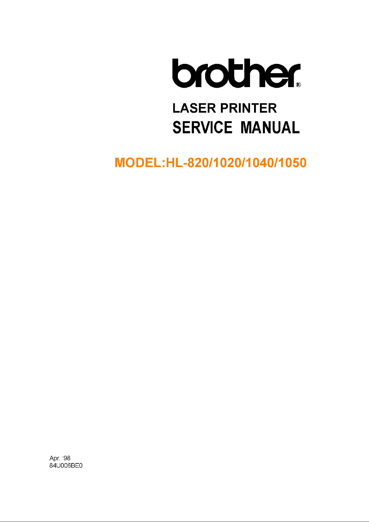
2.4 Paper Loading
(1) Multi-purpose sheet feeder loading
Paper size: A4, Letter, Legal, B5, A5, A6, and Executive. Other sizes of media that
can be handled by the feed mechanism can be loaded.
69.8 to 229 mm
105 to 356mm (face down)
Feeding direction
Feedable paper weight: 60 (16lb.) to 158 (42lb.) g/m
2
Maximum load height : 22mm (200 sheets of 80g/m2 paper) letter or A4 size
Setting method: Pull the MP sheet feeder cover toward you, insert the
stack of paper into the feeder, aligning the top edge of
the sheets, then push the cover back to its original
position.
(2) Manual slot loading
Paper size: Same as in (1) for the multi-purpose sheet feeder.
Feedable paper weight: Same as in (1) for the multi-purpose sheet feeder.
Setting methods: Place the side of the paper to be printed on face down
into the manual feed slot after selecting orientation. Align
the paper at the center of the manual feed slot, and be
sure to insert it fully into the feed slot. Move the paper
guide of the manual feed slot to the paper width.
Cautions:
Before loading paper with holes such as organizer sheets, be sure to fan the stack
well.
When printing on the back of pre-printed paper, be sure to straighten the paper as
much as possible.
2.5 Print Delivery
(1) With the output tray opened
Tray capacity: Maximum 100 sheets (80g/m
(2) With the output tray closed
Tray capacity: 1 sheet (80g/m
Note:
Face down: Deliver the printed face of the paper downward.
Environment : 23°C
2
2
), face-down only
I-5
), face-down only
Page 12
2.6 Paper
(1) Paper type
(a) Normal paper (60 to 157g/m
• A4 size
• Letter size
• Legal size
• B5 (JIS ISO) size
• A5 size
• A6 size
• Executive size
PR98184
2
, specified types of high-quality paper)
* The recommended types of plain paper are as follows:
Letter : Xerox 4200 (75g/m
A4 : Xerox 80 Premier Paper (80g/m
(b) Special paper (specified types)
• Labels
• Envelopes (DL, C4, C5, COM10, Monarch)
• Organizers (K, L, and J sizes of DAY-TIMERS)
(C) Other detailed specifications
Cut Sheet Envelope
Basis Weight 60 to 158 g/m2 (16 to 42 lb.)
Caliper
Moisture Content 4% to 6% by weight 4% to 6% by weight
Smoothness 100 to 250 (Sheffield) 100 to 250 (Sheffield)
0.03 to 0.08 in.
(0.08 to 0.2 mm)
2
)
2
)
2
75 to 90 g/m
single thickness
0.0033 to 0.0058 in.
(0.084 to 0.14 mm)
single thickness
(20 to 24 lb.)
Caution:
Although the printer can handle 9 inches (229mm) width paper such as the C4 size
envelope, you may get stains on the paper outside 8.5 inches width or on the back of
the paper.
It is recommended to use long-grained paper for the best print quality. If short-grained
paper is being used, it might be the cause of paper jams.
Use neutral paper. Do not use acid paper to avoid any damage to the printer drum
unit.
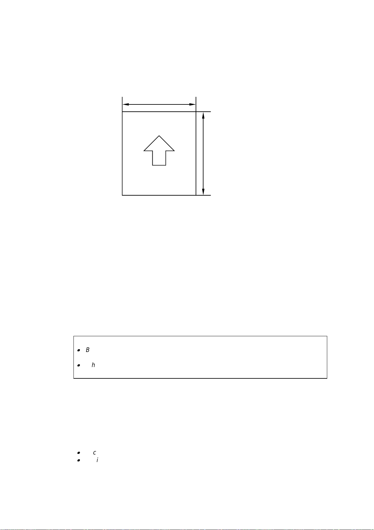
(2) Paper feed conditions
Type Name Feeder Manual feed
60 to 80 g/m
Normal paper (cut sheet) 80 g/m2 paper (Legal)
158 g/m
Labels
Special paper (cut sheet) Envelopes
Organizers
2
2
I-6
(200 sheets)
(100 sheets)
(30 sheets)
(50 sheets)
(10 sheets)
(10 sheets)
Page 13
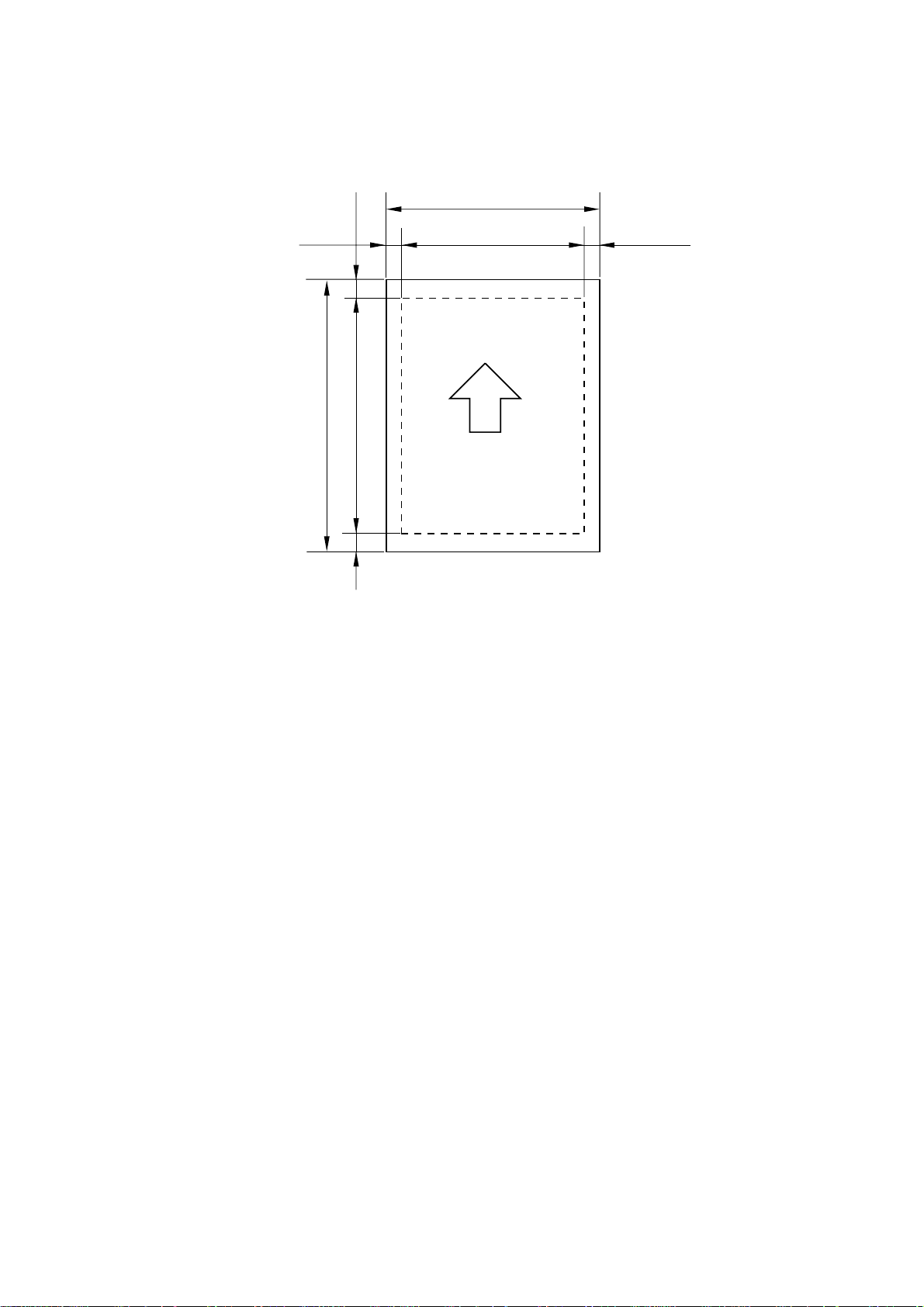
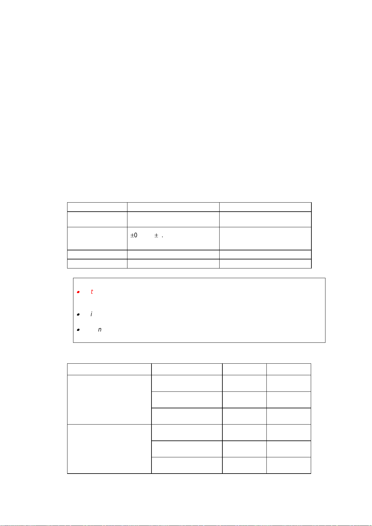
2.7 Effective Printing Area
Printable area
F
E
B
D
F
A
CE
The effective printing area means the area within which the printing of all the data
received without any omissions can be guaranteed.
I-7
Page 14
The table below shows the effective printing areas.
Size A B C D E F
A 4
Letter
Legal
B 5 (JIS)
B 5 (ISO)
Executive
A 5
A6
Organizer
(J size)
Organizer
(K size)
Organizer
(L size)
COM-10
MONARCH
C 4
C 5
DL
(Note that the paper sizes indicated here should conform to the nominal dimensions
specified by JIS.)
210.0mm
8.27”
(2,480 dots)
215.9mm
8.5”
(2,550 dots)
215.9mm
8.5”
(2,550 dots)
182.0mm
7.16”
(2,149 dots)
176.0mm
6.93”
(2,078 dots)
184.15mm
7.25”
(2,175 dots)
148.5mm
5.85”
(1,754 dots)
105.0mm
4.13”
(1,240 dots)
69.85mm
2.75”
(825 dots)
95.25mm
3.75”
(1,125 dots)
139.7mm
5.5”
(1,650 dots)
104.78mm
4.125”
(1,237 dots)
98.43mm
3.875”
(1,162 dots)
228.6mm
9.0”
(2,700 dots)
162mm
6.38”
(1,913 dots)
110mm
4.33”
(1,299 dots)
A4 paper must accommodate 80 characters printed in pica pitch (203.2 mm).
The dot size is based on 300 dpi resolution.
Organizer is not supported by any printer emulations (commands).
297.0mm
11.69”
(3,507 dots)
279.4mm
11.0”
(3,300 dots)
355.6mm
14.0”
(4,200 dots)
257.0mm
10.12”
(3,035 dots)
250.0mm
9.84”
(2,952 dots)
266.7mm
10.5”
(3,150 dots)
210.0mm
8.27”
(2,480 dots)
148.5mm
5.85”
(1,754 dots)
127.0mm
5.0”
(1,500 dots)
171.45mm
6.75”
(2,025 dots)
215.9mm
8.5”
(2,550 dots)
241.3mm
9.5”
(2,850 dots)
190.5mm
7.5”
(2,250 dots)
304.8mm
12.0”
(3,600 dots)
229mm
9.01”
(2,704 dots)
220mm
8.66”
(2,598 dots)
203.2mm
8.0”
(2,400 dots)
203.2mm
8.0”
(2,400 dots)
203.2mm
8.0”
(2,400 dots)
173.5mm
6.83”
(2,007 dots)
164.0mm
6.46”
(1,936 dots)
175.7mm
6.92”
(2,025 dots)
136.5mm
5.37”
(1,612 dots)
93.0mm
3.66”
(1,098 dots)
56.2mm
2.21”
(675 dots)
86.78mm
3.42”
(975 dots)
131.23mm
5.17”
(1,500 dots)
92.11mm
3.63”
(1,087 dots)
85.7mm
3.37”
(1,012 dots)
203.2mm
8.0”
(2,400 dots)
150.0mm
5.9”
(1,771 dots)
98.0mm
3.86”
(1,157 dots)
288.5mm
11.36”
(3,407 dots)
270.9mm
10.67”
(3,200 dots)
347.1mm
13.67”
(4,100 dots)
248.5mm
9.78”
(2,935 dots)
241.5mm
9.5”
(2,852 dots)
258.2mm
10.17”
(3,050 dots)
201.5mm
7.93”
(2,380 dots)
140.0mm
5.51”
(1,654 dots)
118.5mm
4.66”
(1,400 dots)
162.98mm
6.42”
(1,925 dots)
207.43mm
8.17”
(2,450 dots)
232.8mm
9.16”
(2,750 dots)
182.0mm
7.16”
(2,150 dots)
296.3mm
11.66”
(3,500 dots)
220.5mm
8.68”
(2,604 dots)
211.5mm
8.33”
(2,498 dots)
3.4mm
0.13”
(40 dots)
6.35mm
0.25”
(75 dots)
6.01mm
0.24”
(71 dots)
6.35mm
0.25”
(75 dots)
6.01mm
0.24”
(71 dots)
6.35mm
0.25”
(75 dots)
12.7mm
0.5”
(150 dots)
6.01mm
0.24”
(71 dots)
PR98184
4.23mm
0.17”
(50 dots)
I-8
Page 15

3. SAFETY INFORMATION
3.1 Laser Safety (110 - 120V Model only)
This printer is certified as a Class 1 laser product under the US Department of Health and
Human Services (DHHS) Radiation Performance Standard according to the Radiation
Control for Health and Safety Act of 1968. This means that the printer does not produce
hazardous laser radiation.
Since radiation emitted inside the printer is completely confined within the protective
housings and external covers, the laser beam cannot escape from the machine during
any phase of user operation.
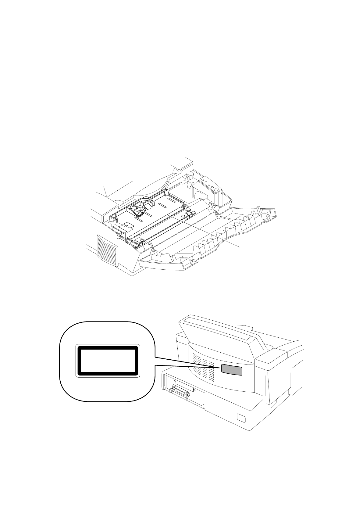
3.2 FDA Regulations (110 - 120V Model only)
The US Food and Drug Administration (FDA) has implemented regulations for laser
products manufactured on and after August 2, 1976. Compliance is mandatory for
products marketed in the United States. One of the following labels on the back of the
printer indicates compliance with the FDA regulations and must be attached to laser
products marketed in the United States.
The label for Japanese manufactured products
MANUFACTURED: K
BROTHER INDUSTRIES, LTD.
15-1, Naeshiro-cho, Mizuho-ku, Nagoya 467-8561, Japan.
This product complies with FDA radiation
performance standards, 21 CFR Subchapter J.
The label for Chinese manufactured products
MANUFACTURED : C
BROTHER Corporation (Asia) Ltd.
Shenzen Buji Nan Ling Factory
Gold Garden Ind., Nan Ling Village, Buji, Rong Gang,
Shenzhen, CHINA
This product complies with FDA radiation
performance standards, 21 CFR Subchapter J.
I-9
Page 16
3.3 Caution for Laser Product (Warnhinweis für Laserdrucker)
CAUTION: When the machine during servicing is operated with the cover open, the
regulations of VBG 93 and the performance instructions for VBG 93 are
valid.
CAUTION: In case of any trouble with the laser unit, replace the laser unit itself. To
prevent direct exposure to the laser beam, do not try to open the enclosure
of the laser unit.
ACHTUNG: Im Falle von Störungen der Lasereinheit muß diese ersetzt werden. Das
Gehäuse der Lasereinheit darf nicht geöffnet werden, da sonst
Laserstrahlen austreten können.
(1) Location of the laser beam window.
Fig. 1-1
(2) Location of Caution Label for Laser Product. (200V only)
CLASS 1LASER PRODUCT
APPAREIL Å LASER DE CLASSE 1
LASER KLASSE 1 PRODUKT
Window
Fig. 1-2
I-10
Page 17
CHAPTER II THEORY OF OPERATION
1. ELECTRONICS
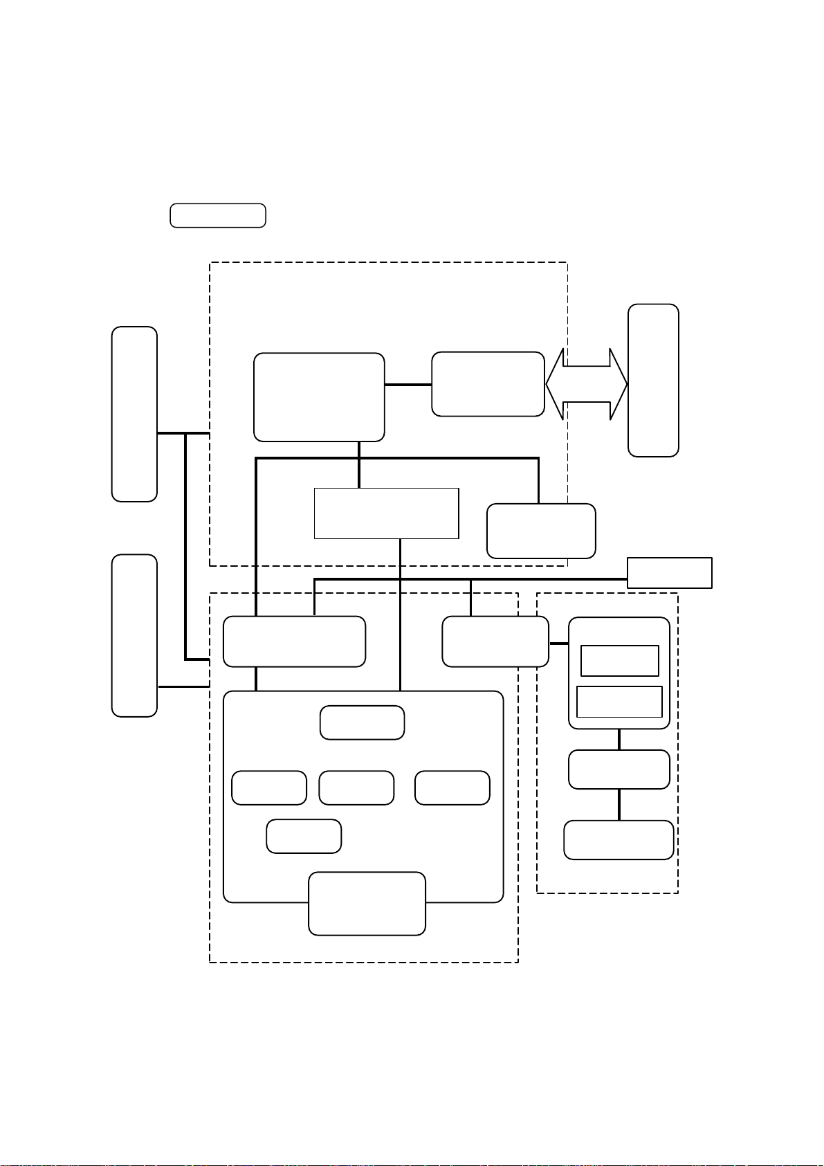
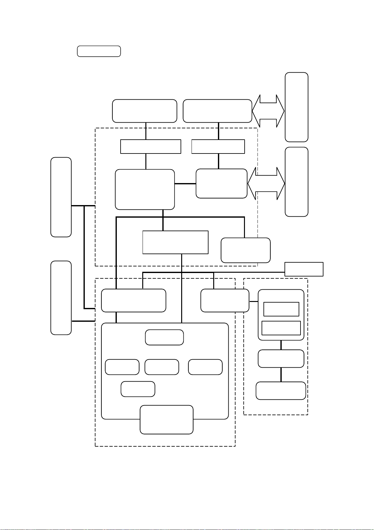
1.1 General Block Diagram
Fig. 2-1 shows a general block diagram of the HL-820/1020 printer.
supply block
Low-voltage power
HL-820/1020
Control system
Video control block
Engine control block
Interface block
External device
Operation block
(Operation panel)
Erase lamp
supply block
High-voltage power
Image generation system
Laser scanner unit
Drum unit
Developing
block
Charging
block
Transfer block
Drum
Toner cartridge
Fig. 2-1
Drive block
(Stepping motor)
Cleaner
block
Paper tray unit
Paper tray
Manual feed
Fixing unit
Paper eject block
Paper feed system
II-1
Page 18
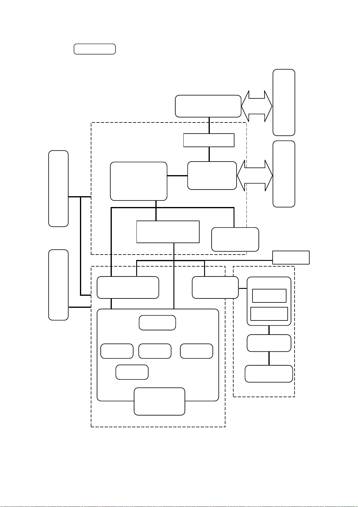
HL-1040
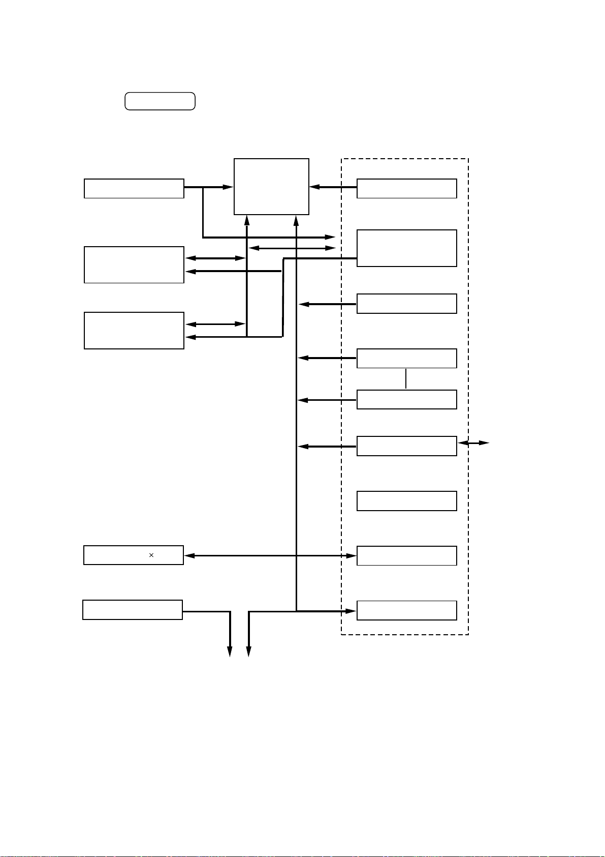
Fig. 2-2 shows a general block diagram of the HL-1040 printer.
Optional I/F board
(Mac. RS-232C)
External deviceExternal device
Control system
Expansion I/O
supply block
Low-voltage power
supply block
High-voltage power
Video control block
Laser scanner unit
Drum unit
Developing
block
Engine control block
Transfer block
Drum
Interface block
Drive block
(Stepping motor)
Cleaner
block
Operation block
(Operation panel)
Erase lamp
Paper tray unit
Paper tray
Manual feed
Fixing unit
Charging
block
Toner cartridge
Image generation system
Paper eject block
Paper feed system
Fig. 2-2
II-2
Page 19
HL-1050
Fig. 2-3 shows a general block diagram of the HL-1050 printer.
Control system
supply block
Low-voltage power
Optional RAM (SIMM)
(max. 32Mbytes)
Expansion memory I/O Expansion I/O
Video control block
Engine control block
Optional I/F board
(Mac. RS-232C)
Interface block
External deviceExternal device
Operation block
(Operation panel)
Erase lamp
supply block
High-voltage power
Image generation system
Laser scanner unit
Drum unit
Developing
block
Charging
block
Transfer block
Drum
Toner cartridge
Fig. 2-3
Drive block
(Stepping motor)
Cleaner
block
Paper tray unit
Paper tray
Manual feed
Fixing unit
Paper eject block
Paper feed system
II-3
Page 20
1.2 Main PCB Block Diagram
HL-820/1020
Fig. 2-4 shows the block diagram of the main PCB.
Reset Circuit
Program + Font ROM
512 Kbytes
RAM
(2.0 Mbytes)
CPU Core
(MC68EC000)
BUS
A S I C
Oscillator (15.3MHz)
INT
Address Decoder
DRAM Control
Timer
FIFO
EEPROM (128 8 bits)
Motor Driver
To Panel Sensor PCB
DATA EXTENSION
CDCC Parallel I/O
Soft Support
EEPROM I/O
Engine Control I/O
To PC
Fig. 2-4
II-4
Page 21
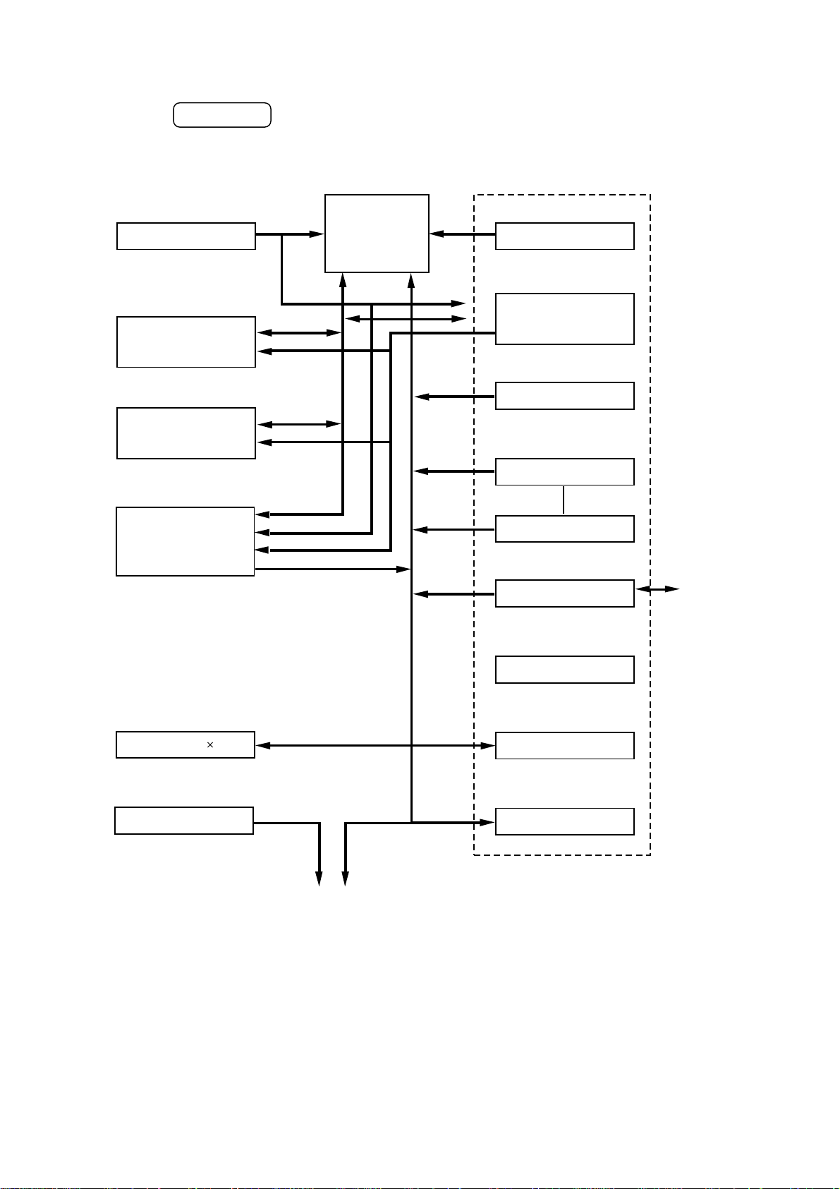
Fig. 2-5 shows the block diagram of the main PCB.
Reset Circuit
Program + Font ROM
512 Kbytes
RAM
(2.0 Mbytes)
HL-1040
CPU Core
(MC68EC000)
BUS
A S I C
Oscillator (15.3MHz)
INT
Address Decoder
DRAM Control
Timer
FIFO
Option Serial I/O
(RS232C & RS422A)
EEPROM (128 8 bits)
Motor Driver
To Panel Sensor PCB
Fig. 2-5
DATA EXTENSION
CDCC Parallel I/O
Soft Support
EEPROM I/O
Engine Control I/O
To PC
II-5
Page 22
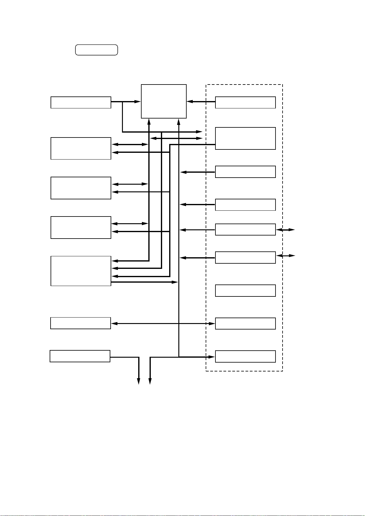
Fig. 2-6 shows the block diagram of the main PCB.
Reset Circuit
Program + Font ROM
4.0 Mbytes
RAM
(4.0 Mbytes)
HL-1050
CPU Core
(MB86831)
BUS
A S I C
Oscillator (33.3MHz)
INT
Address Decoder
DRAM Control
Timer
FIFO
Option RAM (SIMM)
(max. 32Mbytes)
Option Serial I/O
(RS232C & RS422A)
EEPROM (512 x 8 bits)
Motor Driver
To Panel Sensor PCB
CDCC Parallel I/O
USB I/O
Soft Support
EEPROM I/O
Engine Control I/O
To PC
To PC
Fig. 2-6
II-6
Page 23
1.3 Main PCB
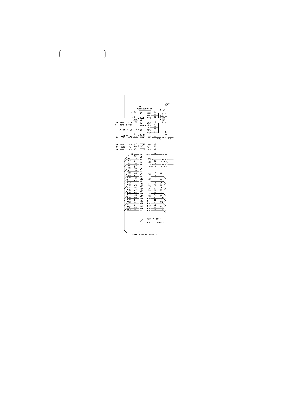
1.3.1 CPU Core
HL-820/1020/1040
Fig. 2-7 shows the CPU circuit block on the main PCB.
The CPU is a Motorola MC68EC000FN16 which is driven with a clock frequency of
15.3MHz. This clock frequency is made by dividing the source clock of 30.67 MHz into
two.
Fig. 2-7
II-7
Page 24
HL-1050
Fig. 2-8 shows the CPU circuit block on the main PCB.
The CPU is a Motorola MB86831 which is driven with a clock frequency of 33MHz. The
CPU itself runs at 66MHz.
Fig. 2-8
II-8
Page 25

1.3.2 ASIC
HL-820/1020/1040
The ASIC is composed of a Cell Based IC that contains the following functional blocks.
(1) Oscillator circuit
Generates the main clock for the CPU by dividing the source clock frequency into
two.
(2) Address decoder
Generates the CS for each device.
(3) DRAM control
Generates the RAS, CAS, WE, OE and MA signals for the DRAM and controls
refresh processing (CAS before RAS self-refreshing method).
(4) Interrupt control
Interrupt levels:
Priority High 7 NMI
6 FIFO
5 EXINT(Option Serial I/O)
4 BD / Timer 1
3 SCANINT
2 CDCC / BOISE / DATA EXTENSION
Low 1 Timer 2
(5) Timers
The following timers are incorporated:
Timer 1 16-bit timer
Timer 2 10-bit timer
Timer 3 Watch-dog timer
(6) FIFO
A 5,120-bit FIFO is incorporated. Data for one raster scan is transferred from the
RAM to the FIFO by DMA transmission and is output as serial video data. The
data cycle is 10.22 MHz.
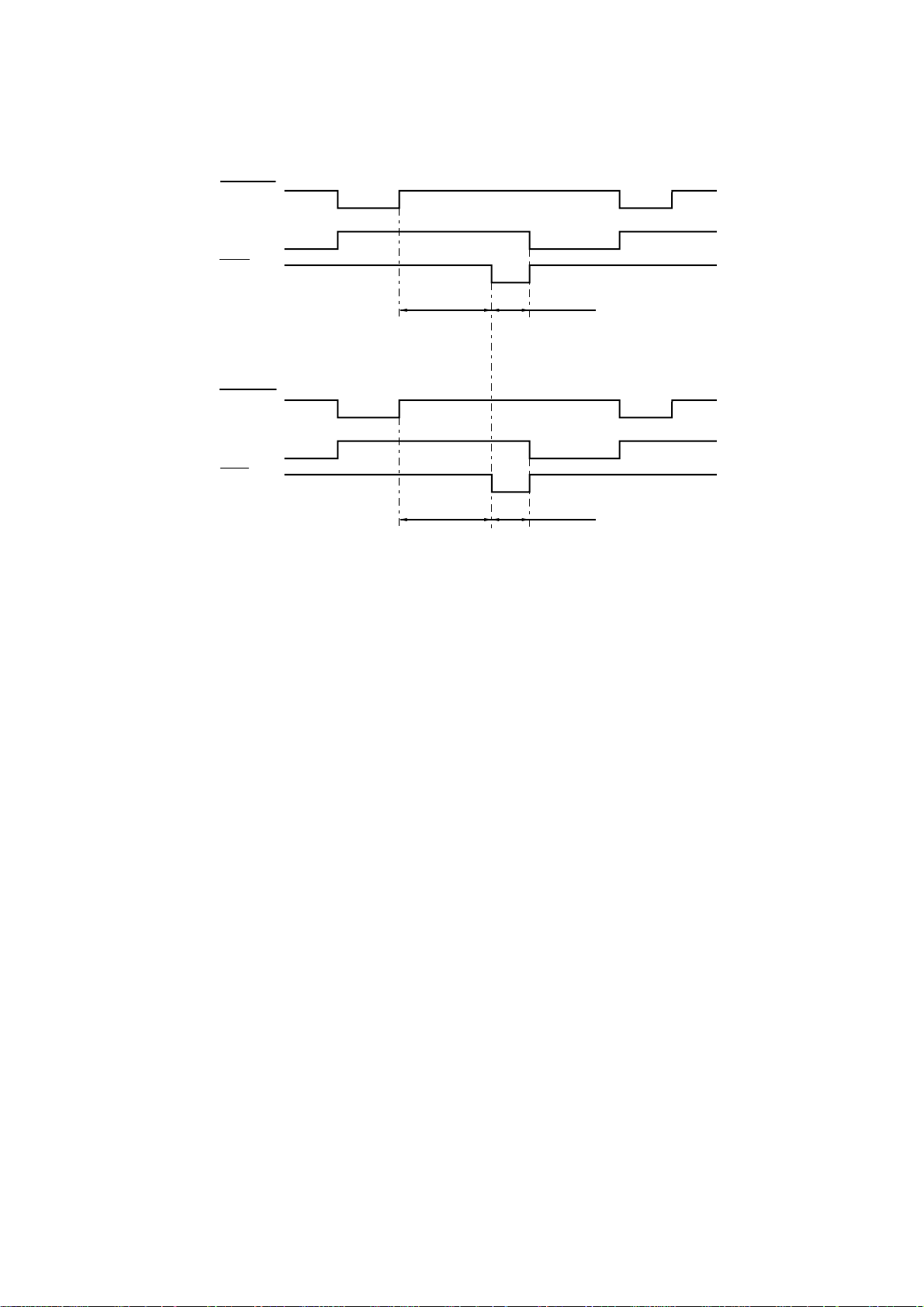
(7) CDCC parallel I/O
<Data receiving>
There are two modes in this unit. One is the CPU receiving mode and the other is
the DMA receiving mode. In the CPU receiving mode the CPU receives the
command data from the PC, and after the CPU is switched to the DMA mode, it
receives the image data and writes to the DRAM directly.
II-9
Page 26
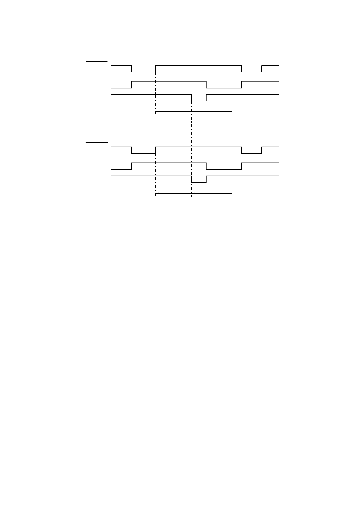
CPU Receive Mode
STROBE
BUSY
ACK
90 µsec
0.5 µsec
DMA Receive Mode
STROBE
BUSY
ACK
0.5 µsec1.5 µsec
BUSY goes HIGH at the falling edge of STROBE. The data (8 bits) from the PC is
latched in the data buffer at the rising edge of STROBE. The pulse width of ACK
differs according to the speed MODE as shown above. BUSY goes LOW at the
rising edge of ACK.
<IEEE1284 support>
This supports the IEEE1284 data transfer with the following modes.
Nibble mode
Byte mode
(8) Data expansion
This circuit expands the compressed image data received from the PC, and writes
the bit map data to the FIFO.
(9) Software support
Supports 16 x 16 rotation, bit expansion, and bit search.
(10) EEPROM I/O
One output port and one I/O port are assigned.
II-10
Page 27
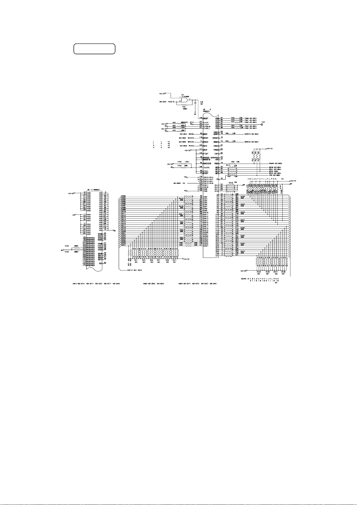
(11) Engine control I/O
This I/O is used for the connection to the panel sensor PCB. It controls the main
motor, solenoid, sensors, etc.
Fig. 2-9
II-11
Page 28

HL-1050
The ASIC is composed of a Cell Based IC that contains the following functional blocks.
(1) Oscillator circuit
Generates the main clock for the CPU.
(2) Address decoder
Generates the CS for each device.
(3) DRAM control
Generates the RAS, CAS, WE, OE and MA signals for the DRAM and controls
refresh processing (CAS before RAS self-refreshing method).
(4) Interrupt control
Interrupt levels:
Priority High 10 Reserve interrupt 1 (for debug)
9 Watch Dog Timer
8 LSB EMPTY (for VDO FIFO)
7 Timer 1
6 USB
5 XIO interrupt (RS-100M) or MIO interrupt
4 BD (for engine check)
3 Reserve interrupt 2
2 CDCC
Low 1 Timer 2
Note:
All the interrupts can be masked.
The priority of levels 7, 6, and 5 are changeable from the program.
(5) Timers
The following timers are incorporated:
Timer 1 32-bit timer
Timer 2 32-bit timer
Timer 3 Watch-dog timer
(6) FIFO
A 10Kbit FIFO is included. Data for one raster scan is transferred from the RAM to
the FIFO by DMA transmission and is output as serial video data. The data cycle is
10.43MHz.
(7) Parallel I/O
<Data receive Mode>
There are two modes in this unit. One is the CPU receive mode and the other is
the DMA receive mode. In the CPU receive mode the CPU receives the command
data from the PC, and after the CPU is switched to the DMA mode, it receives the
image data and writes it to the DRAM directly.
II-12
Page 29
CPU Receive Mode
STROBE
BUSY
ACK
90 µsec
0.5 µsec
DMA Receive Mode
STROBE
BUSY
ACK
0.5 µsec1.5 µsec
BUSY goes HIGH at the falling edge of the STROBE signal. The data (8 bits) from
the PC is latched into the data buffer at the rising edge of the STROBE signal. The
pulse width of ACK varies according to the speed MODE as shown above. BUSY
goes LOW on the rising edge of ACK.
<IEEE1284 support>
This supports the IEEE1284 data transfer with the following mode.
Nibble mode
Byte mode
ECP mode
(8) Data expansion
This circuit expands the compressed image data received from the PC, and writes
the bit map data to the FIFO.
(9) Software support
Supports 16 x 16 rotation, bit expansion, bit search, and decimal point conversion.
(10) EEPROM I/O
One output port and one I/O port are assigned.
II-13
Page 30
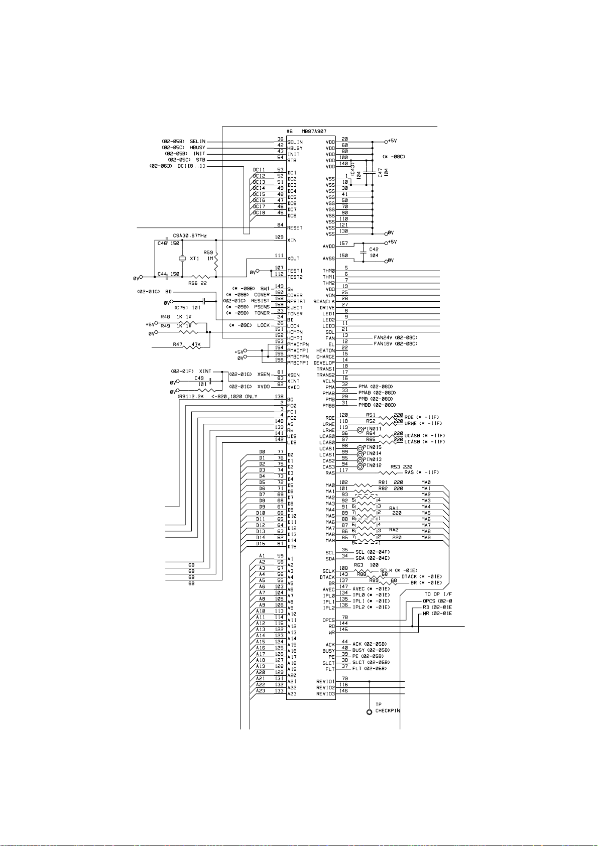
(11) Engine control I/O
This I/O is used for the connection to the panel sensor PCB. It controls the main
motor, solenoid, sensors, etc.
Fig. 2-10
II-14
Page 31

1.3.3 ROM
HL-820/1020/1040
A program file of 512 Kbytes and the font data are stored in the ROM. A 42-pin IC socket
is provided: a 16 Mbits ROM (42-pin) is mounted into this socket normally, but a 4 Mbits
ROM (40-pin) can be mounted by leaving the 1st and 42nd pins of the socket open
circuit.
Fig. 2-11
HL-1050
A program file of 4.0 Mbytes and the font data are stored in the ROM. Two 42-pin IC
sockets are provided: two 16 Mbits ROMs (42-pin) can be mounted into these sockets.
Fig. 2-12
II-15
Page 32

1.3.4 DRAM
HL-820/1020/1040
A 16M-bit DRAM (x 16bits) is used as the RAM.
Fig. 2-13
HL-1050
Two 16M-bit DRAMs (x 16bits) are used as the RAM.
Fig. 2-14
II-16
Page 33

1.3.5 Optional RAM
HL-1050
A 32bit (72 pin) SIMM can be fitted as optional RAM. The main PCB has one slot and the
capacity of SIMM can be from 1 Mbyte to 32 Mbytes.
Fig. 2-15
II-17
Page 34

1.3.6 Optional Serial I/O
HL-1040/1050
The interrupt of the serial I/O is input to the EXINT terminal of the ASIC, and is
recognized by th e C P U . A 3 2 - b y t e r e g i s t e r i s p r o v i d e d for this I/O, which is read
and written to by the CPU.
Fig. 2-16
1.3.7 EEPROM
HL-820/1020/1040
The EEPROM is an XL24C01AF type of two-wire method with a 128 x 8 bits
configuration.
M62320FP is an IC which transfers the data received from the serial I/O to the parallel
I/O.
Fig. 2-17
HL-1050
The EEPROM is XL24C04AF type of two-wire method with a 512 x 8 bits configuration.
Fig. 2-18
II-18
Page 35

1.3.8 Reset Circuit
HL-820/1020/1040
The reset IC is a PST598DNR. The reset voltage is 4.2V (typ.) and the LOW period of
reset is 200ms (typ).
Fig. 2-19
HL-1050
The reset IC is a PST596DNR. The reset voltage is 4.2V (typ.) and the LOW period of
reset is 50ms (typ).
Fig. 2-20
1.3.9 CDCC I/O
HL-820/1020/1040
Fig. 2-21 shows the CDCC interface circuit.
Fig. 2-21
II-19
Page 36

HL-1050
Fig. 2-22 shows the CDCC interface circuit.
Fig. 2-22
II-20
Page 37

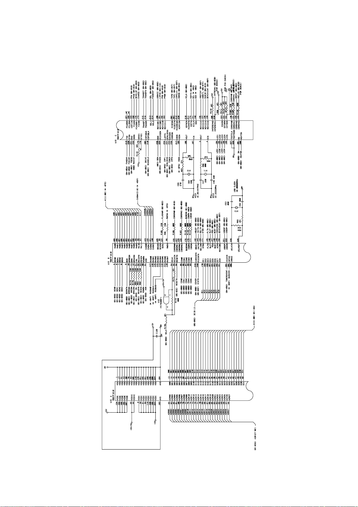
1.3.10 Engine I/O
HL-820/1020/1040
Fig. 2-23 shows the engine interface circuit.
Fig. 2-23
II-21
Page 38

HL-1050
Fig. 2-24 shows the engine interface circuit.
Fig. 2-24
II-22
Page 39

1.3.11 Paper Feed Motor Drive Circuit
HL-820/1020/1040
The motor driver is a TR array. The excitation method is 2-2 phase excitation with a
bipolar drive.
Fig. 2-25
HL-1050
The motor driver is a TR array. The excitation method is 2-2 phase excitation with a
bipolar drive.
Fig. 2-26
II-23
Page 40

1.4 Panel Sensor PCB
The following parts are on the panel sensor.
• Control Panel...........1 Switch, 4 lamps
• Connector................Low-voltage, high-voltage, solenoid, main motor, toner sensor,
• Registration sensor
1.5 Power Supply
1.5.1 Low-voltage Power Supply
The power supply uses a switching regulation system to generate the regulated DC
power (+5V and +24V), which are converted from the AC line.
The regulated output and the production code of each power supply vary depending on
the printer model as listed below;
Model Regulated Output Production Code
HL-820/1020/1040
HL-1050
laser, polygon motor, connector for main PCB
+5V / 0.6 A
+24V / 2.0 A
+5V / 1.2A
+24V / 2.0A
100V: MPW1547
200V: MPW1447
100V: MPW1550
200V: MPW1450
(Heater)
Fuse
Line
Filter
Lightning
Surge
Absorber
Rectifier Oscillator
24V
Regulation
Circuit
Heater
Circuit
Feedback
Thermal
Fuse
(Panel Sensor Circuit)
24V
Lamp
5V
Regulation
Circuit
Fig. 2-27
II-24
5V
Page 41

1.5.2 High-voltage Power Supply
This generates and outputs the voltages and currents for the charging, development and
transfer functions.
24VI
GND
R1
Current
Regulator
B1
Voltage
Regulator
VR22
Current
Regulator
B81 Q81
Voltage
Regulator
B101 Q101
Current
Regulator
Supply
Roller
Developing
Roller
Photosensitive
Drum
Corona
Unit
Transfer Roller
Cleaner
Roller
PAPER
SENSOR
PC141
B121 Q121
Voltage
Regulator
Z51 VR51
Voltage
Regulator
VR71
Voltage
Regulator
VR61
Fig. 2-28
II-25
Page 42

2. MECHANICS
2.1 Overview of Printing Mechanism
Hopper
Plate
Registration Sensor Lever
Toner Cartrid
Polygon Mirror
Papers
ge
Laser Scanner
Multi-purpose Sheet Feeder
Manual Paper Path
MP Feeder Cover
Paper Pick-up Roller
Paper Feed
Roller
Pinch Roller
Toner Empty
Sensor
Supply Roller
Drum Unit
Blade
Scanner Unit
Transfer
Roller
Corona Wire
Photosensitive Drum
Erase Lamp
Fixing Unit
Development
Roller
Cleaning Roller
Pressure Roller
Eject Roller
Eject Sensor
Actuator
Heat Roller
Thermistor
Main Cotrol PCB
Panel
Sensor
PCB
Fig. 2-29
EL PCB
Scanner Unit
Main Motor
Sub Motor
Main Fan Motor
Sub Fan Motor
HighVoltage
Power
Supply
Toner
Empty
Sensor
PCB
Thermistor (for Heat roller)
Solenoid
Primary Charger (Corona Wire)
Primary Charger (Grid)
Developer Roller
Transfer Roller
Cleaner Roller
Supply Roller
Eject Sensor
Registration Sensor
Toner Empty Sensor
Thermistor (for Toner)
Fig. 2-30
II-26
Page 43

2.2 Paper Transfer
2.2.1 Paper Supply
The pick-up roller picks up one sheet of paper from the paper feeder every time it is
rotated and feeds it to the paper feed roller.
p
Hopper plate
Separation pad
Fig. 2-31
Pick-up roller
Registration sensor lever
The paper is gripped between the pick-up roller and the separation pad and separated
into individual sheets.
The pick-up roller is directly connected to the sector gear, whose rotation is forcibly
stopped by the gear stopper. When the pick-up solenoid is activated, the clutch
mechanism is engaged by the solenoid action and the sector gear is driven; when it has
completed one full turn its rotation is stopped again by the gear stopper. The paper
drawn out by the pick-up roller pushes against the top of form sensor lever and the paper
top position/absence of paper is detected by sensing the motion of the lever.
2.2.2 Paper Registration
When paper picked up from the multi-purpose sheet feeder (MPF) pushes against the top
of form sensor actuator, the registration sensor lever is caused to turn, and the photo
sensor detects this motion. When this signal from the sensor is detected the paper feed
roller is stopped temporarily by the clutch. The paper is fed to the nip point between the
paper feed roller and the pinch roller in the multi-purpose sheet feeder, and the skew of
the paper is corrected by pushing the leading edge of the paper against the nip point.
When the paper feed roller starts to be rotated again when it is released by the clutch,
paper with the leading edge correctly aligned, is fed by the paper feed roller and is
transported to the transfer roller.
Paper
Paper feed roller
Clutch mechanism (engaged/released by the solenoid assembly)
Released when the solenoid is ON and engaged when the solenoid is OFF.
Pinch roller
Transfer roller
Drum
Fig. 2-32
II-27
Page 44

2.2.3 Paper Eject
,
,
The completion of paper eject is detected in the following manner:
(a) When the leading edge of the paper pushes down the eject sensor actuator
located in the fixing unit, the photo sensor (photo interrupter) is opened and
detects the start of paper eject.
(b) When the trailing edge of the paper has passed through the paper eject sensor
actuator, the photo sensor is closed and the completion of paper eject is
recognized.
Transfer roller
Pressure roller
Eject sensor actuator
Eject roller
Drum
Heat roller
Eject sensor actuator
High-voltage power
suppl
y PCB
Fig. 2-33
Paper
Sensor
Eject sensor actuator
Sensor
Fig. 2-34
II-28
Page 45

2.3 Sensors
2.3.1 Cover Sensor
Detects opening and closing of the top cover.
Top Cover
Cover Switch
Toner Empty
Sensor
Fig. 2-35
2.3.2 Toner Empty Sensor
Detects if there is toner in the toner cartridge. It also detects whether or not the drum unit
is installed. (The toner cartridge is installed in the drum unit).
Fig. 2-36
II-29
Page 46

2.4 Drum Unit
2.4.1 Photosensitive Drum
Generates the latent electrostatic image and develops the image on the drum surface.
2.4.2 Primary Charger
Forms a uniform charge on the drum surface.
(1) Corona wire
Generates the ion charge on the drum.
(2) Grid
Spreads the ion charge evenly over the drum surface.
2.4.3 Development Roller
Develops the latent electrostatic image on the drum surface by the addition of the toner.
2.4.4 Transfer Roller
Transfers the toner image to the paper from the drum surface.
2.4.5 Cleaner Roller
Removes and recycles the toner remaining on the drum surface.
2.4.6 Erase Lamp
Discharges the electrostatic latent image on the drum.
2.5 Print Process
2.5.1 Charging
The drum is charged to approx. +1150V by an ion charge which is generated by the
primary charger. The charge is generated by ionization of the corona wire, which has a
DC bias from the high-voltage power supply applied to it. The flow of the ion charge is
controlled by the grid to ensure it is distributed evenly on the drum surface. The drum
sleeve is regulated to approx. 280V by the voltage regulator.
Voltage
Regulator
1150V
-
+
-
+
+
+
Corona wire
280V
-
-
-
-
-
-
---
+
+
+
+
+
+
+
+
+
+
+
+
+
+
+
+
+
Fig. 2-37
Aluminum drum sleeve
Organic Photoconductor layer
Grid
HVPS
Passive Type
Voltage Regulator
Drum
The primary charge uses a corona wire, but since the drum is positively charged, only
less than 1/10 of the usual quantity of ozone is generated compared with the negatively
charged drum. The level of ozone expelled from the printer is therefore not harmful to the
human body. Applicable safety standards have been complied with.
II-30
Page 47

2.5.2 Exposure Stage
After the drum is positively charged, it is exposed to the light emitted from the laser unit.
Laser detector
Drum
Paper
Laser beam
f lens
Polygon mirror
Laser diode
Motor
Lens
Fig. 2-38
Laser Beam
The area exposed to the laser beam is the image to be printed. The surface potential of
the exposed area is reduced, forming the electrostatic image to be printed.
+1150
1 Cycle of drum
123
(a)
4
Primary charging
1
2
Laser beam exposure and developing
(a) Unexposed area
( Non image area )
(b) Exposed area
( Image area )
+700
Surface Potential (V)
+400
+300
Drum
Sleeve
(b)
Time
Fig. 2-39
3
Transfer the image to paper
Erase the residual potential
4
II-31
Page 48

2.5.3 Developing
(a)
]
(b)
]
g
Developing causes the toner to be attracted to the electrostatic image on the drum so as
to transform it into a visible image.
The developer consists of a non-magnetic toner. The development roller is made of
conductive rubber and the supply roller (which is also made of conductive sponge) rotate
against each other. The toner is charged and carried from the supply roller to the
development roller. The toner adheres to the development roller and is conveyed to the
drum at an even thickness controlled by the blade. The toner is nipped between the
development roller and the drum and developed onto the latent image on the drum. The
electrostatic field between the drum and the development roller, which is DC-biased from
the high-voltage power supply, creates the electrostatic potential to attract toner particles
from the development roller to the latent image area on the drum surface.
Blade
Toner
Separator
Auger
Develop housing
Supply roller
SR-bias
2.5.4 Transfer
(a) Transfer process
After the drum has been charged and exposed, and has received a developed
image, the toner formed is transferred onto the paper by applying a negative
charge to the back of the paper. The negative charge applied to the paper causes
the positively charged toner to leave the drum, and adhere to the paper. As a
result, the image is visible on the paper.
(b) Cleaning process of transfer roller
If the toner is not transferred onto the paper perfectly, it is possible that there may
be residual toner on the drum which will adhere to the transfer roller. The transfer
voltage changes to a positive voltage during non-printing rotation of the drum.
Therefore the transfer roller is cleaned by returning the positively charged toner
adhering to the transfer roller onto the photo-conductive drum.
DC-bias
Transfer roller
Development
roller
Fig. 2-40
Cleanin
Transfer process [ON
Cleaning process [ON
Drum
Erase lamp
(a) Collecting process
(b) Discharging process
roller
II-32
Page 49

2.5.5 Drum Cleaning Stage
,,,
,
,,
,,,,
,,,,,
,,,,,
,,,,
,,
,
,,,
,,
,,,,
,,
,
,
,
,
In the image transfer stage, not all the toner on the photosensitive drum is transferred
onto the paper but some remains on the drum. In the drum cleaning stage, the drum
surface is cleaned by the cleaning roller, so that residual toner on the drum surface is
removed and collected on the cleaning roller itself. The residual toner on the cleaning
roller will be discharged to the drum during starting or non-printing time. The toner will be
collected by the developing roller and reused (for further developing).
2.5.6 Erasing Stage
Before the cleaning stage, the drum surface is exposed to the light emitted from the
erase lamp (LED lamp). This stage prepares the drum by decreasing its surface voltage
uniformly, ready to receive a uniform charge in the primary charging stage.
2.5.7 Fixing Stage
The image transferred to the paper by static electricity is fixed by heat and pressure when
passing through the heat roller and the pressure roller in the fixing unit. The thermistor
ASSY keeps the surface temperature of the heat roller constant by detecting the surface
temperature of the heat roller and turning on or off the halogen heater lamp.
Pressure roller
Thermistor ASSY
Halogen heater lamp
Heat roller
Cleaner ASSY
Fig. 2-41
II-33
Page 50

CHAPTER III DISASSEMBLY AND REASSEMBLY
1. SAFETY PRECAUTIONS
To avoid creating secondary problems by mishandling, be careful to follow the following
precautions during maintenance work.
(1) Always turn off the power switch and unplug the power cord from the power outlet
before accessing any parts inside the printer.
(2) Be careful not to lose screws, washers, or other parts removed.
(3) Be sure to apply grease to the gears and applicable positions specified in this
chapter.
(4) When using soldering irons or other heat-generating tools, take care not to
accidentally damage parts such as wires, PCBs, and covers.
(5) Before handling any PCBs, touch a metal portion of the equipment to discharge
any static electricity charge on your body, or the electronic parts or components
may be damaged.
(6) When transporting PCBs, be sure to wrap them in the correct protective packaging.
(7) Be sure to replace self-tapping screws correctly, if removed. Unless otherwise
specified, tighten screws to the following torque values.
TAPTITE, BIND or CUP B
M3 : 7kgf • cm
M4 : 10kgf • cm
TAPTITE, CUP S
M3 : 8kgf • cm
SCREW
M3 : 7kgf • cm
M4 : 8kgf • cm
(8) When connecting or disconnecting cable connectors, hold the connector body, not
the cables. If the connector has a lock, release the connector lock first to release
it.
(9) After a repair, check not only the repaired portion but also all connectors. Also
check that other related portions are functioning properly before operational
checks.
III-1
Page 51

2. DISASSEMBLY FLOW
PS PCB ASSY
HIGH-VOLTAGE
MAIN FAN MOTOR
12
LOW-VOLTAGE
PS PCB ASSY
11
14
DRIVE UNIT
15
MAIN MOTOR ASSY
16
SUB MOTOR ASSY
17
B
BOTTOM
MAIN PCB ASSY
8
A
OUTPUT TRAY ASSY
1
BASE PLATE ASSY
9
B
DRUM UNIT
2
PANEL SENSOR PCB ASSY
10
TOP COVER
3
SUB FAN MOTOR ASSY
13
REAR COVER
MP SHEET FEEDER ASSY
4
5
III-2
FIXING UNIT
6
A
SCANNER UNIT
7
PAPER SUPPORT
EXTENSION SUPPORT WIRE
19
18
Page 52

3. DISASSEMBLY PROCEDURE
3.1 Output Tray ASSY
(1) Open the output tray toward you.
(2) Press the hinges at the left and right sides of the output tray inwards to release the
output tray from the main cover.
Output Tray
Output Tray
Main Cover
3.2 Drum Unit
(1) Open the top cover.
(2) Lift out the drum unit.
Fig. 3.1
Drum Unit
Top Cover
Main Cover
Fig. 3.2
III-3
Page 53

3.3 Top Cover
(1) Open the top cover.
(2) Press the hinges at the left and right sides of the top cover inwards to release the
top cover from the main cover.
Note:
It is recommended for easy removal to press the side of the top cover (
the side of the main cover (
Main Cover
➁
).
) while pulling
➀
Top Cover
2
1
Top Cover
3.4 Rear Cover
(1) Remove the two M4x12 tapping screws.
(2) Remove the rear cover.
Taptite, bind M4x12
Rear Cover
Main Cover
Main Cover
Fig. 3-3
Multi-purpose Sheet Feeder
Taptite, bind M4x12
Fig. 3-4
Note:
When re-assembling the rear cover, hook the two hooks at the right and left hand side
(rear), then secure the two screws.
III-4
Page 54

3.5 MP Sheet Feeder ASSY
Caution:
When disassembling the MP sheet feeder ASSY, if you get the grease on your fingers,
take care not to touch the separation pad or the paper pick-up roller, the grease spread to
the paper and the drum unit. It might cause black spots to appear on the printed page.
(1) Push the left rib outwards and pull out the MP sheet feeder. It is not necessary to
release the right rib.
Multi-purpose
Sheet Feeder
Rib
Fig. 3-5
Note:
When re-assembling, apply a suitable amount of grease (2 rice-grain size) between the
heat sink of the motor and the ground leaf spring in case of grease shortage. (Refer to
the figure below.)
Ground leaf spring
Grease: FLOIL GE-676
(or FLOIL GE-334C)
Fig. 3-6
Motor heat sink
6.2MM
III-5
Page 55

3.6 Fixing Unit
g
(1) Remove the two M4x16 tapping screws.
(2) Lifting the fixing unit, disconnect the thermistor connector on the EL PCB first, then
the two heater harnesses.
Taptite, cup M4x16
Thermistor connector
Fixing Unit
Taptite, cup M4x16
EL PCB
Thermistor harness
Heater harness (Brown)
Heater harness
(Blue)
Fig. 3-7
Note:
The eject sensor actuator may also be removed when removing the fixing unit. In this
case be sure to re-assemble the eject sensor actuator when re-assembling the fixing unit.
(3) Remove the two M3x12 tapping screws.
(4) Open the fixing unit cover along the open side of the fixing unit cover.
Fixing unit cover
Taptite, bind M3x12
Fixing unit
vr
Pressure roller
Shaft
Fixin
unit frame
Fig. 3-8
III-6
Page 56

PR98292
j
(5) Release the right side of the paper eject roller shaft.
(6) Remove the four eject pinch rollers and the pinch springs from the fixing unit
frame. Then, remove the pinch spring from each pinch roller.
Paper eject roller shaft
Pinch Spring
E
ect Pinch Roller
Fig. 3-8a
(7) Remove the M3x10 self tapping screw securing the connector plate.
(8) Remove the connector plate from the fixing unit frame and loosen the other M3x10
tapping screw securing the fixing unit cover.
(9) Remove the idle gear 16 from the fixing unit frame to remove the heat roller. Then,
Caution :
Never touch the surface of the halogen heater lamp and the heat roller.
Heat Roller Washer
Retaining ring
Heat roller gear
Taptite, pan M3x10
Connector plate
remove the halogen heater lamp from the heat roller.
Halogen heater lamp
(Blue 100V, Red 200V)
Groove
Heat Roller Bearing
Idle gear 16
Heat roller
Fixing unit frame
Heat Roller Bearing
Taptite, pan
M3x10
Fig. 3-9
Note:
When re-assembling the bearing at the both ends of the heat roller, ensure that the
direction of the bearing is correct referring to the above figure.
The heat roller itself is very similar to the one for HL-1060/1070 printers. The heat
roller for the HL-820/1020/1040/1050 printers can be distinguished by the groove on
the edge of the roller. (Refer to the above figure.)
III-7
Page 57

When replacing the heat roller cleaner with a new one, attach the cleaner referring to
,
the figure below;
Follow the instructions below when installing the thermistor in the fixing unit.
-1mm ~ +1mm
4mm ~ 5mm
Fig. 3-10
i) Place the cleaner felt of the cleaner ASSY for the thermistor under the heat roller.
ii) Place the end of the thermistor on the heat roller.
iii) Insert boss1 of the thermistor into the hole of the fixing unit frame.
iv) Do no place the thermistor on boss2 of the fixing unit frame.
Boss2
Thermistor
Heat Roller
3.7 Scanner Unit
(1) Remove the three M4x12 tapping screws.
(2) Lift out the scanner unit.
Taptite, bind M4x12
Scanner Unit
Boss1
Fixing unit frame
Cleaner ASSY for thermistor
Fig. 3-11
Taptite, bind M4x12
Main cover
Panel Sensor PCB
Fig. 3-12
III-8
Page 58

Note:
When replacing the scanner unit, ensure to assemble the ferrite core using the cable
binder as follows;
Ferrite Core
Cable binder
Flat cable
LD harness
Fig. 3-13
(3) Disconnect the three connectors from the panel sensor PCB.
(4) Remove the M3x8 tapping screw, and lift the toner sensor PCB from the scanner
unit.
Caution:
Never touch the inside of the scanner unit or the mirror when disassembling or
reassembling. If there is any dirt or dust on the mirror, blow it off.
Taptite, cup M3x8
Toner Sensor PCB
Fig. 3-14
III-9
Scanner Unit
Page 59

3.8 Main PCB ASSY
(1) Remove the three M4x6 screws.
(2) Hold the hooks at the left and right of the mounting frame to pull out the main PCB
ASSY.
Screw, pan M4x6
Screw, pan M4x6
Hook
Main PCB ASSY
Hook
Fig. 3-15
3.9 Base Plate ASSY
Caution:
Prior to turning the printer upside-down, ensure that the drum unit has been removed
from the printer.
(1) Turn the printer upside down.
(2) Remove the eight M4 and five M3 self tapping screws.
Taptite, bind M4x12
Taptite, cup M3x6
Taptite, bind M4x12
Base plate ASSY
Taptite, cup M3x6
Taptite, bind M4x12
Taptite, bind M4x12
Fig. 3-16
III-10
Page 60

(3) Lift the base plate ASSY and remove the grounding screw.
y
3.10 Panel Sensor PCB ASSY
Fig. 3-17
Base Plate ASSY
Ground wire
Screw pan(washer),
M3.5x6
Low-voltage Power
Suppl
PCB ASSY
(1) Remove the main shield.
(2) Remove the M4x12 screw securing the panel sensor PCB ASSY.
Taptite, bind M4x12
Main shield
C
Panel Sensor PCB ASSY
Fig. 3-18
A
Main shield
Panel Sensor PCB ASSY
B
Note:
When re-assembling the main shield, ensure that you fit PCB A to underneath the
main shield.
When re-assembling the panel sensor PCB, ensure that you fit the PCB into hook B
and hook C first. Then, fit the two bosses to the PCB and secure the screw.
III-11
Page 61

Panel Sensor
PCB ASSY
10
9
8
7
(3) Disconnect the eight connectors from the PCB. (Three connectors have already
been disconnected when removing the scanner unit.)
1
2
3
Main frame
4
5
Fig. 3-19
6
(Name of the Harnesses)
1. Low-voltage harness
2. Erase lamp harness
3. Toner harness
4. Scan motor flat cable
5. Laser harness
6. Solenoid harness
7. Main / sub motor connector
8. Fan motor 1 harness
9. Fan motor 2 harness
10. High-voltage flat cable
Note:
When re-assembling, the cable connectors must be inserted securely into the PCB
connectors and the PCB must not be stressed by the harnesses.
The connectors should be inserted by matching the housing color and the number of
pins.
3.11 Low-voltage Power Supply PCB ASSY
(1) Remove the one M4x12 tapping screw securing the low-voltage power supply PCB
ASSY.
(2) Disconnect the two connectors for the heater harness and the LV harness from the
PCB.
Low-voltage Power Supply ASSY
Hr hrn
LV harness
Fig. 3-20
III-12
Page 62

(3) Remove the one M4x12 screw to remove the inlet holder. Then, remove the inlet
and the PCB.
Note:
When re-assembling the inlet holder and AC inlet, be sure to insert the part A of the
holder into the hole of the ferrite core.
Inlet Holder
A
AC Inlet
Main Cover
Ferrite Core
Fig. 3-21
3.12 High-voltage Power Supply PCB ASSY
(1) Remove the one M4x12 screw securing the high-voltage power supply PCB ASSY.
(2) Remove the film covering the PCB.
(2) Disconnect the HV flat cable from the PCB.
Taptite, bind
M4x12
Insulation Sheet
High-voltage Power
Supply PCB ASSY
HV flat cable
Fig. 3-22
III-13
Main Cover
Page 63

3.13 Sub Fan Motor ASSY
,
(1) Slide the sub fan motor ASSY upwards.
Manufacturer sticker side
Main Cover
Note:
When re-assembling the sub fan motor, ensure that the side on which the manufacturers
sticker is attached is facing the main frame.
Sub Fan Motor
Fig. 3-23
3.14 Main Fan Motor ASSY
(1) Remove the two M4x12 screws securing the fan motor holder.
(2) Remove the fan motor holder from the printer.
(3) Remove the main fan motor from the fan motor holder.
Taptite, bind
M4x12
Fan Motor
Fan motor holder
bind M4x12
Taptite
Manufacturer sticker side
Main frame
Fig. 3-24
III-14
Page 64

Note:
When re-assembling the fan motor
into the holder, refer to the figure on
the right.
3.15 Drive Unit
(1) Unhook the heater harness from the drive unit.
PR980109
Fan motor holder
Fan Motor
Fig. 3-25
Heater harness
Drive Unit
Ferrite Core
(HL-1050 only)
Ferrite Core
(HL-1050, 200V only)
Hook
Fig. 3-26
(2) Remove the three M4x20 and one M4x12 screws securing the drive unit.
Taptite, cup M4x20
Taptite, cup M4x12
Ferrite Core
(HL-1050 only)
Electrode DRB1
Ferrite Core
Motor harness
Fig. 3-27
(HL-1050, 100V only)
III-15
Page 65

Note:
When re-assembling the drive unit, ensure that you fit the drive unit underneath the
electrode DRB1.
When disassembling the drive unit, be sure to remove the eight ferrite cores of two
types on the heater harness and the motor harness. (Refer to the figures in the
previous page, Fig. 3-26 and Fig. 3-27.) The place where the bigger core should be
assembled varies depending on the model.
3.16 Main Motor ASSY
(1) Remove the two M3x6 screws securing the main motor.
(2) Remove the main motor ASSY.
Taptite, bind M3x6
Drive Unit
3.17 Sub Motor ASSY
(1) Remove the two M3x6 screws securing the sub motor.
(2) Remove the sub motor ASSY.
p i in M x
T
Main Motor ASSY
Fig. 3-28
Fig. 3-29
III-16
Sub Motor ASSY
Page 66

3.18 Paper Support
(1) Pull the paper support down toward you and pull both legs outwards to release it.
MP Sheet Feeder
3.19 Extension Support Wire
(1) Raise the extension support wire toward you and press both legs inward to release
it.
Paper Support
Fig. 3-30
Output Tray
Extension Support Wire
Fig. 3-31
III-17
Page 67

4. PACKING
Accessory carton
Pad
Documents
Carton
Printer
Bag
Pad
Fig. 3-32
III-18
Page 68

CHAPTER IV MAINTENANCE AND TROUBLESHOOTING
1. INTRODUCTION
1.1 Initial Check
(1) Operating environment
Check if :
• The source voltage stays within ±10% from the rated voltage shown on the rating
plate.
• The printer is installed on a solid, level surface.
• The room temperature is maintained between 10°C and 32.5°C. The relative
humidity is maintained between 20% and 80%.
• The printer is not located in a dusty place.
• The printer is not exposed to ammonia fumes or other harmful gases.
• The printer is not located in a hot or humid area (such as near water or a
humidifier).
• The printer is not exposed to direct sunlight.
• The room is well-ventilated.
• The printer is not placed where the ventilation hole of the printer is blocked.
(2) Print paper
Check if :
• A recommended type of print paper is being used. [If the paper is too thick or too
thin, or tends to curl, paper jams or paper feed problems may occur, or printed
images may be blurred.]
• The print paper is damped. [If so, use fresh paper, and check whether the print
quality improves or not.]
• The print paper is short-grained paper or acid paper. [If so, print quality problems
may occur. For further information, refer to paper specifications in Chapter II.]
(3) Consumables
Check if :
• The Toner lamp is not lit on the control panel when a toner cartridge is installed in
the printer. [If the lamp is lit, replace the cartridge with a new one. If blank spots
occur on printouts, take out the drum unit and slowly rock it to redistribute the
toner evenly.]
(4) Others
Condensation:
When the printer is moved from a cold room into a warm room in cold weather,
condensation may occur inside the printer, causing various problems as listed
below:
• Condensation on the optical surfaces such as the scanning mirror, lenses, the
reflection mirror and the protection glass may cause the print image to be light.
• If the photosensitive drum is cold, the electrical resistance of the photosensitive
layer is increased, making it impossible to obtain the correct contrast when
printing.
IV-1
Page 69

• Condensation on the corona unit may cause corona charge leakage.
• Condensation on the hopper gate and separation pad may cause paper feed
troubles.
If condensation has occurred, wipe the effected units or parts with a dry cloth.
If the drum unit is unpacked soon after it is moved from a cold room to a warm room,
condensation may occur inside the unit, which may cause incorrect images. Instruct the
user to allow the unit to come to room temperature before unpacking it. This will take one
or two hours.
1.2 Basic Procedure
If a malfunction or incorrect print appears, make an initial check following the basic
procedure below:
(1) Check the error lamps following the inspection procedure described later in
this section. If no error lamps are lit, see Section 4 for troubleshooting information.
(2) If any defective image output is found, follow the image defect fault descriptions in
this section.
IV-2
Page 70

2. CONSUMABLE PARTS
2.1 Drum Unit
The Drum lamp is on when the drum unit is nearly at the end of its life.
Life expectancy: 20,000 pages at 20 pages per job
8,000 pages at 1 page per job
Note:
There are many factors that determine the actual drum life, such as temperature,
humidity, type of paper and toner that you use, the number of pages per print job, etc..
2.2 Toner Cartridge
Toner low: The Data and Alarm lamps blink once every five seconds.
Toner empty: The Data and Alarm lamps blink once every second.
Life expectancy: 2,400 pages/new toner cartridge
(when printing A4- or letter-size paper at 5% print coverage)
Note:
Toner life expectancy will vary depending on the type of average print job printed.
2.3 Periodical Replacement Parts
No. Description Part No. Qty se r v i c e l i f e ( number of prints) Remarks
1
Fixing Unit UL8750001 1 (50,000) 120V
Fixing Unit UL8751001 1 (50,000) 230V
2 Scanner Unit UL8748001 1 (50,000 or more)
3 MP sheet feeder ASSY UL8749001 1 (50,000 or more)
Note:
The above table shows only estimated values. They are subject to change without prior
notice.
IV-3
Page 71

3. IMAGE DEFECTS
Print out test print out test print out test Print out test print o
Print out test print out test print out test Print out test print o
Print out test print out test print out test Print out test print o
Print out test print out test print out test Print out test print o
Print out test print out test print out test Print out test print o
Print out test print out test print out test Print out test print o
Print out test print out test print out test Print out test print o
Print out test print out test print out test Print out test print o
Print out test print out test print out test Print out test print o
Print out test print out test print out test Print out test print o
Print out test print out test print out test Print out test print o
Print out test print out test print out test Print out test print o
Print out test print out test print out test Print out test print o
3.1 Image Defect Examples
I-2 DarkI-1 Light I-2 Dark I-3 Completely blank I-4 All black
I-5 Dirt on back of paper I-6 Black vertical
streaks
I-8 Black vertical
streaks
I-12 Image distortion
I-9 White vertical
streaks
Print out test print out test print out test Print out test print o
Print out test print out test print out test Print out test print oPrint out test print o
Print out test print out test print out test Print out test print o
Print out test print out test print out test Print out test print oPrint out test print o
Print out test print out test print out test Print out test print oPrint out test print o
Print out test print out test print out test Print out test print o
Print out test print out test print out test Print out test print oPrint out test print o
Print out test print out test print out test Print out test print o
Print out test print out test print out test Print out test print oPrint out test print o
Print out test print out test print out test Print out test print o
Print out test print out test print out test Print out test print oPrint out test print o
Print out test print out test print out test Print out test print o
Print out test print out test print out test Print out test print oPrint out test print o
Print out test print out test print out test Print out test print o
Print out test print out test print out test Print out test print oPrint out test print o
Print out test print out test print out test Print out test print o
Print out test print out test print out test Print out test print oPrint out test print o
Print out test print out test print out test Print out test print o
Print out test print out test print out test Print out test print oPrint out test print o
Print out test print out test print out test Print out test print o
Print out test print out test print out test Print out test print oPrint out test print o
Print out test print out test print out test Print out test print o
Print out test print out test print out test Print out test print oPrint out test print o
Print out test print out test print out test Print out test print o
Print out test print out test print out test Print out test print oPrint out test print o
Print out test print out test print out test Print out test print o
I-13 Faint print I-14 White spots
I-6 Black vertical
streaks
I-10 Faulty
registration
Print out test print o
Print out test print o
Print out test print o
Print out test print o
Print out test print o
Print out test print o
Print out test print o
Print out test print o
Print out test print o
Print out test print o
Print out test print o
Print out test print o
Print out test print o
I-7 Black horizontal
stripes
I-11 Poor fixing
I-15 Black spots
I-16 Black band
I-20 Horizontal lines
I-17 Gray background I-18 I-19 Downward fogging
Hollow print
of solid black
I-21 Light rain
I-22 Ghost
Fig. 4.1
IV-4
Page 72

3.2 Troubleshooting Image Defects
The following procedures should be followed in the event of specific image defects.
See subsection 3.3 for information about the location of the high-voltage contacts and
grounding contacts.
Caution:
Print quality can not be guaranteed in the following cases;
When using the printer for a special job, such as printing of name cards.
When printing much narrower paper than printable paper width.
When printing on one area of the paper continuously even though Letter or A4-size
paper is used.
I-1 Light
Possible cause Step Check Result Remedy
Toner sensing
failure
(printer side)
Toner sensing
failure
(toner cartridge
side)
Drum
connection
failure
High-voltage
power supply
PCB failure
Panel sensor
PCB or main
PCB failure
Scanner unit
failure
1 Can printing be started with the
drum unit removed?
2 Is the problem solved when 4
or 5 pages are printed after the
toner cartridge is replaced with
a full one?
3 Are all the contacts (HV, GND)
connected when the drum unit
is installed?
4 Check the harness connection
between the high-voltage
power supply PCB and the
panel sensor PCB.
5 Perform the same check as
step 4 above and also between
the panel sensor PCB and the
main PCB.
6 Is the problem solved by
replacing the scanner unit?
Yes Toner sensor failure.
Check if the toner
sensor needs
cleaning and check
the toner sensor
connection.
Yes The wiper of the
toner cartridge is
defective.
Replace the toner
cartridge.
No Clean contact
electrodes both in the
printer body and on
the drum unit.
No If the connection is
normal, replace the
high-voltage power
supply PCB.
No Replace the panel
sensor PCB or the
main PCB.
Yes Replace the scanner
unit.
HV.GND
contacts
(Fig.4-5)
➀
IV-5
Page 73

I-2 Dark
Possible cause Step Check Result Remedy
Corona failure
(soiled wire)
Corona failure
(contact failure)
Drum unit failure 3 Is the problem solved when the
High-voltage
power supply
PCB
Main PCB 5 Are there any disconnected
Panel sensor
PCB
1 Is the corona wire dirty? Yes Clean the corona wire
by using the wire
cleaner.
2 Are the corona electrodes
between the printer body and
drum unit dirty?
drum unit is replaced?
4 Are there any disconnected
connectors?
connectors?
6 Are there any disconnected
connectors?
No Clean both electrodes.
Yes Replace the drum
unit with a new one.
No Replace the high-
voltage power supply
PCB.
No Replace the main
PCB.
No Replace the panel
sensor PCB.
HV.GND
contacts
(Fig.4-5)
➇
➅
IV-6
Page 74

I-3 Completely blank
Possible cause Step Check Result Remedy
Developing bias
contact failure
Drum unit 2 Are the drum shaft and drum
Drum unit failure 3 Is the problem solved after the
Scanner harness
connection failure
Main / Panel
sensor PCB
connection failure
1 Are the developing bias
contacts between the printer
body and drum unit dirty?
electrode of the printer body
connected correctly? No Che c k t h e c onnection
drum unit is replaced?
4 Is the scanner harness
connected securely?
Is there any play in the
connection?
5 Are printing signals being input
to the scanner?
Is the problem solved after the
main PCB or the panel sensor
PCB replaced?
Yes Clean the electrodes
at both sides.
Yes Clean the shaft and
the electrode.
between the shaft and
the electrode.
Yes Replace the drum
unit.
No Reconnect the
connector properly.
Yes Replace the main
PCB or the panel
sensor PCB.
HV.GND
contacts
(Fig.4-5)
➆
➀
➀
Scanner unit
failure
6 Scanner interlock lever
damaged.
Scanner mirror is broken or
loose.
IV-7
Yes Replace the scanner
unit.
No Replace the high-
voltage power supply
PCB.
Page 75

I-4 All black
Possible cause Step Check Result Remedy
Corona failure 1 Is the corona wire of the drum
unit broken?
2 Are the electric terminal
springs in the printer body and
the electrode on the bottom
face of the drum unit dirty?
Harness
connection
High-voltage
power supply
PCB
Ditto 5 Perform the same check as in
Main PCB 6 Is the problem solved after
3 Is the scanner unit connected
with the panel sensor PCB
correctly?
4 Is the problem solved after
high-voltage power supply
PCB replaced?
step 3.
main PCB is replaced?
Yes Replace the drum
unit.
Yes Clean the terminals
in the printer and on
the drum.
No Check the harness
connection between
the scanner unit and
the panel sensor
PCB.
Yes Replace the high-
voltage power supply
PCB.
Yes Replace the panel
sensor PCB.
Yes Replace the main
PCB.
HV.GND
contacts
(Fig.4-5)
➅
Panel sensor
PCB
7 Is the problem solved after the
panel sensor PCB is replaced?
Yes Replace the panel
sensor PCB.
IV-8
Page 76

I-5 Dirt on the back of paper
Possible cause Step Check Result Remedy
Fixing unit 1 Is the pressure roller dirty?
Is any other area in the printer
dirty?
Dirt in the drum
unit
2 Is the transfer roller dirty?
Is the problem solved after the
drum unit is replaced?
Note: Clean the pressure roller as follows;
(1) Set three or more sheets of paper in the MP sheet feeder.
(2) Open the top cover.
(3) Turn on the power switch while holding down the switch on the control panel.
(4) Release the panel switch when the Drum lamp is on.
(5) Close the top cover.
(6) Hold down the panel switch until the Ready lamp is on, then release the
switch.
(7) Print three patterns; grid, zip and solid black.
(8) Turn off the power switch with the top cover closed.
(9) Set paper in the manual slot with the solid black side up.
(10) Turn on the power switch while holding down the switch on the control panel.
(11) Release the panel switch when the Drum lamp is on.
(12) Press the panel switch again and release it immediately.
(13) Print a page of test pattern while cleaning the pressure roller.
Yes Clean the pressure roller.
(See the following note.)
Yes Replace the drum unit
No Replace the high-voltage
power supply PCB.
IV-9
Page 77

I-6 Black and blurred vertical streaks
Possible cause Step Check Result Remedy
Corona failure 1 Is the corona wire dirty? Yes Clean the corona
wire with the wire
cleaner.
Corona failure 2 Is the vertical block streak
about 10mm wide?
Is the corona wire cleaner not
in its home position?
Dirt in the paper
feed system
Scratch on the
drum
Cleaning failure 5 Is the drum surface dirty with
Scratch on the
heat roller
3 Is the paper tray or feed
system on the drum unit soiled
with toner?
4 Is the drum surface scratched? Yes Replace the drum
toner in streaks?
6 Is the surface of the heat roller
scratched?
Yes Return the wire
cleaner to its home
position.
Yes Clean the toner off.
unit.
Yes Replace the drum
unit.
Yes Replace the fixing
unit.
Note:
If you print the same pattern continuously, the drum will be worn and black vertical
streaks will appear on the paper.
HV.GND
contacts
(Fig.4-5)
➇
I-7 Black and blurred horizontal stripes
Possible cause Step Check Result Remedy
Scratch on the
drum
Toner stuck on
the developer
roller
Scratch on the
fixing roller
High-voltage
power supply
PCB
1 Are the horizontal stripes at
94mm (OPC drum) intervals?
2 Are the horizontal stripes at
25mm (developer roller)
intervals?
3 Are the horizontal streaks at
63mm (heat roller) intervals?
4 Is the problem solved after the
high-voltage power supply
PCB is replaced?
Yes Replace the drum unit.
Yes Print several sheet and see
what happens.
The problem will disappear
after a while. If not, replace the
drum unit.
Yes Replace the fixing unit.
Yes Replace the high-voltage
power supply PCB.
IV-10
Page 78

I-8 Black vertical streaks (in a gray background)
Possible cause Step Check Result Remedy
Translucent
stain on the
scanner window
1 Are there any stains on the
scanner window?
Yes Clean the scanner window.
If it is not effective, replace the
scanner unit.
I-9 White vertical streaks
Possible cause Step Check Result Remedy
Scanner window
dirty
Transfer failure 2 Is the transfer roller scratched? Yes Replace the drum unit.
1 Is the scanner window dirty? Yes Clean the scanner window with
a dry tissue.
I-10 Faulty registration
Possible cause Step Check Result Remedy
Excessive paper
load
Print paper 2 Is the specified weight of the
Ditto 3 Is the first printing position
Paper resist
sensor position
incorrect
1 Is the paper loaded in the
paper feeder more than 22mm
deep?
recommended paper being
used?
within ±1mm of the tolerance
specification?
4 Is the position of the paper
resist sensor normal?
Yes Instruct the user to keep paper
loads below 22mm in depth.
No Instruct the user to use the
recommended types of paper.
Yes Adjust the Y offset by using the
utility software supplied.
No Reposition the sensor to the
correct position.
IV-11
Page 79

I-11 Poor fixing
Possible cause Step Check Result Remedy
Printing paper 1 Is thick paper more than 42lb
weight in use?
Toner sensing
failure
Thermistor
failure
Low-voltage
power supply
PCB failure
2 Is the problem solved by
replacing the drum unit or the
toner cartridge?
(When printing is faint.)
3 Is the thermistor fitted
correctly?
4 Is the problem solved by
replacing the low-voltage
power supply PCB?
I-12 Image distortion
Yes Instruct the user to use paper
of the recommended weight
and thickness.
Yes Toner is empty.
The toner sensing is defective,
clean the toner sensor.
If the wiper in the toner
cartridge is broken, replace the
toner cartridge with a new one.
No Fit the thermistor correctly.
Yes Replace the low-voltage power
supply PCB.
Possible cause Step Check Result Remedy
Scanner 1 Is the scanner unit secured to
the frame incorrectly?
Is there any play?
Scanner LD
emission failure
Scanner motor
rotation failure
Scanner
connection
failure
2 Is the laser diode or the laser
scanner motor defective?
3 Is the scanner harness
connected properly?
Is it coming loose?
IV-12
Yes Secure the unit correctly and
tighten the screws.
Yes Replace the scanner unit.
Yes Connect the harness correctly.
Page 80

I-13 Faint print
Print out test print out test print out test Print out test print oPrint out test print o
Print out test print out test print out test Print out test print oPrint out test print o
Print out test print out test print out test Print out test print oPrint out test print o
Print out test print out test print out test Print out test print oPrint out test print o
Print out test print out test print out test Print out test print oPrint out test print o
Print out test print out test print out test Print out test print oPrint out test print o
Print out test print out test print out test Print out test print oPrint out test print o
Print out test print out test print out test Print out test print oPrint out test print o
Print out test print out test print out test Print out test print oPrint out test print o
Print out test print out test print out test Print out test print oPrint out test print o
Print out test print out test print out test Print out test print oPrint out test print o
Print out test print out test print out test Print out test print oPrint out test print o
Print out test print out test print out test Print out test print oPrint out test print o
Print out test print out test print out test Print out test print oPrint out test print o
Print out test print out test print out test Print out test print oPrint out test print o
Print out test print out test print out test Print out test print oPrint out test print o
Print out test print out test print out test Print out test print oPrint out test print o
Print out test print out test print out test Print out test print oPrint out test print o
Print out test print out test print out test Print out test print oPrint out test print o
Print out test print out test print out test Print out test print oPrint out test print o
Print out test print out test print out test Print out test print oPrint out test print o
Print out test print out test print out test Print out test print oPrint out test print o
Print out test print out test print out test Print out test print oPrint out test print o
Print out test print out test print out test Print out test print oPrint out test print o
Print out test print out test print out test Print out test print oPrint out test print o
Print out test print out test print out test Print out test print oPrint out test print o
Possible cause Step Check Result Remedy
Printer not level 1 Is the printer placed
horizontally?
Drum unit 2 Does the problem happened
immediately after replacing the
No Place the printer on a flat
surface.
Yes Remove and carefully shake
the drum unit horizontally.
drum unit with a new one?
Scanner window
dirty
Scanner unit
failure
3 Is the window of the laser
scanner dirty?
4 Is the problem solved by
replacing the scanner unit?
Yes Clean the scanner window with
a dry tissue.
Yes Replace the scanner unit.
I-14 White spots
Possible cause Step Check Result Remedy
Toner cartridge 1 Is the toner in the toner
cartridge almost empty?
Print paper 2 Is the problem solved after
change to specified freshly
unpacked paper?
Environment 3 Check if the problem still
appears after the printer has
warmed up.
IV-13
Yes Shake the drum unit
horizontally. Replace the toner
cartridge with a new one.
No Replace the drum unit.
Yes Recommend the user to
change the paper.
(Damp (wet) paper might be
used.)
Yes Replace the drum unit.
Advise the user of the
specified print environment.
Page 81

I-15 Black spots
Possible cause Step Check Result Remedy
Drum unit 1 Are the spots at 94mm
intervals?
The problem is not solved after
printing a few pages.
Fixing unit 2 Are the spots at 63mm
intervals?
The problem is not solved after
printing a few pages.
High-voltage
power supply
PCB
3 Is the problem solved after the
high-voltage power supply
PCB is replaced?
Yes If toner remains stuck, wipe it
off gently with a cotton swab.
Replace the drum unit if the
OPC drum is scratched or
deteriorated (exposed).
(Refer to the following note.)
Yes Check and clean the heat roller
with a cloth dampened with
alcohol.
Replace the fixing unit.
Yes Replace the high-voltage
power supply PCB.
Note: Clean the drum unit as follows:
(1) Place the printing samples in front of the process unit, and find the exact
position of the image defect.
Position of smudge on
the drum
94mm interval
Fig. 4-2
(2) Turn the drum gear by hand while looking at the surface of the OPC drum.
Fig. 4-3
IV-14
Page 82

(3) Wipe the surface of the photosensitive drum with a cotton swab until the dust
g
or paper powder on the surface comes off.
Toner cartrid
Caution:
Do not wipe the surface of the photosensitive drum with something sharp. (ball-point
pen etc.)
Use the cleaning liquid which is a 50-50 mixture of ethyl alcohol and pure water.
Separator
e
Paper path
Cleaning roller
Photo sensitive drum
Fig. 4-4
I-16 Black band
Possible cause Step Check Result Remedy
Drum unit 1 Is the wire cleaner positioned
at its home position?
Ditto 2 Is the corona wire dirty? Yes Clean the corona wire.
No Return the wire cleaner to its
home position.
If the problem still appears
after cleaning, replace the
drum unit.
IV-15
Page 83

I-17 Gray background
Note:
This problem may appear on the first 10 to 20 pages immediately
after replacing the toner cartridge.
Possible cause Step Check Result Remedy
Print paper 1 Does the paper being used
meet the paper specification
(weight, etc.).
Drum unit 2 Is the problem solved after
replacing the drum unit?
Note: The following cases increase the possibility of this problem.
1) The drum unit is at the end of its life.
2) There is dust or paper powder.
3) A large amount of paper whose width is narrower than A4 is printed.
4) Acid paper is being used.
I-18 Hollow print
No Recommend to change the
paper to a specified type of the
paper.
Yes Recommend to change the
paper to a fresh pack paper.
Yes Replace the drum unit.
No Replace the high-voltage
power supply PCB.
Possible cause Step Check Result Remedy
Print paper 1 Is thick paper of more than
42lb being used or extremely
rough surface paper?
IV-16
Yes Recommend to use the
specified type of paper.
No Refer and compare with I-14.
Page 84

I-19 Downward fogging of solid black
Possible cause Step Check Result Remedy
Drum unit 1 Is the problem solved after
replacing the drum unit?
High-voltage
power supply
PCB
2 Is the problem solved after
replacing the high-voltage
power supply PCB?
Yes Replace the drum unit.
Yes Replace the high-voltage
power supply PCB.
I-20 Horizontal lines
Possible cause Step Check Result Remedy
SR electrode 1 Are the SR electrodes
between the printer body and
the drum unit dirty?
Yes Clean both electrodes.
HV.GND
contacts
(Fig.4-
5,4-7)
➈
SR connection
failure
Feed roller 3 Are the feed roller shaft and
2 Are the SR electrodes
between the printer body and
the drum unit connected
correctly?
the ground contact
connected correctly?
IV-17
No Check the SR
connection.
No Check the connection
between the shaft and
the ground contact.
➉
Page 85

I-21 Light rain
Possible cause Step Check Result
Drum unit failure 1 Is the problem solved after
Yes Replace the drum unit.
replacing the drum unit with
one that does not contain a
starter sheet**?
High-voltage
power supply
PCB failure
2 Is the problem solved after
replacing the high-voltage
power supply PCB?
Yes Replace the high-voltage
**Note:
Make sure to use a used drum unit which has already ejected the starter sheet. It is not
possible to find the drum unit failure if you use a new drum unit with a starter sheet in it.
I-22 Ghost
Remedy
power supply PCB.
Possible cause Step Check Result
Driver setting 1 Is thin paper such as 64g/m
2
Yes Change the current mode to
used under the thick paper
mode?
IV-18
Remedy
the normal mode from the
driver setting.
Print 5 or 6 blank pages if this
problem occurs.
Page 86

3.3 Location of High-voltage Contacts and Grounding Contacts
Grounding contacts
➀
➈
pp
Drum unit
For supply roller
➂
For transfer
roller
➃
For cleaning
roller
Fig. 4-5
High-voltage contacts
➆
For development
➇
Wire cleaner
➄
➅
For development
roller
roller
For supply roller
For transfer
roller
For cleaning
roller
For corona wire
For grid
For cleaning roller
For transfer roller
For corona wire
For development
roller
For grid
Fig. 4-6
IV-19
Page 87

3.4 Location of Feed Roller Shaft and Grounding Contacts
Feed shaft roller
Fig. 4-7
➉
For feed roller
IV-20
Page 88

4. PAPER JAM
Problem Type of jam Cause Temp measure
Jam at power on Paper stuck Paper feed sensor or
paper eject sensor is
turned on.
Top of paper stopped
at 20mm from the
fixing unit.
Paper feed roller
rotated twice.
Top of paper stopped
at 250mm from the
fixing unit.
Next paper is not fed.
Top paper stopped
between the paper
feed roller and the
pick-up roller.
Paper was fed approx.
20mm from the pickup roller.
Top of paper stopped
at 17mm from the
contact point of the
heat roller and
pressure roller.
Jam occurred after
ejecting paper.
Top of paper stopped
at 20mm from the
fixing unit.
No paper Paper feed sensor is
not turned on.
Jam caused by paper
length detected as
longer than 400mm (16
inches).
Jam caused by paper
length detected as
shorter than 80mm.
Jam caused by a paper
feed delay.
Jam caused by the
paper sensed as not
being ejected from the
paper eject sensor.
Same as above. Same as above.
1. Cover open
2. Bug
Paper feed sensor is
not returning properly,
and is not turned off.
Paper feed sensor
was turned off early.
Malfunction of
actuator or hardware
noise.
Due to paper dust or
rubber of the pick-up
roller wear, paper was
not fed in at the
proper timing.
Paper eject sensor
does not work
properly and is not
turned off.
(single printing)
(continuous printing)
1. Cover is not closed
properly.
2. Bug
Remove the paper inside
the printer. If there is no
paper, check the
suspect sensors
referring to note and
clear the problem.
Check paper feed
sensor motion referring
to note and clear the
problem.
Check paper feed
sensor motion referring
to note and clear the
problem.
Check sensors referring
to note and clear the
cause of the problem.
Remove the paper dust
attached to the pick-up
roller. If the rubber is
worn out, replace it with
new one.
Check the sensor motion
referring to note and
clear the problem.
Same as above.
1. Check if the drum unit
is installed correctly.
2. Please inform BIL.
Note: How to check the sensors
(1)Open the cover.
(2)Power on the printer while pressing the panel switch.
(3)Release the panel switch.
(4)Press and release the panel switch.
Results:
*Alarm Lamp is ON = Paper feed sensor is turned ON
*Drum Lamp is ON = Paper eject sensor is turned ON
IV-21
Page 89

5. TROUBLESHOOTING MALFUNCTIONS
When carrying out countermeasures for malfunctions as described in this section, check
connectors for contact failure before measuring the voltage at the specified connector
pins.
M-1 No AC power supplied
Possible cause Step Check Result Remedy
Supply voltage 1 Is the correct voltage present
at the outlet?
Power plug 2 Is the power cord securely
plugged into the outlet?
Fuse (F1, F2) 3 Is the fuse blown? Yes If the fuse blows again
Wiring 4 Unplug the power supply plug.
Is there a broken wire between
the AC input connector of the
low-voltage power supply and
the power plug?
No Inform the user that the correct
voltage is not supplied at the
outlet.
No Plug the power cord securely
into the outlet.
immediately after replacing the
low-voltage power supply PCB,
check that there is not a short
circuit somewhere in the AC
power supply line.
Yes Replace the AC power cord.
M-2 No DC power supplied
Possible cause Step Check Result Remedy
AC power
supply
1 Is AC power supplied between
connectors CN1-L and CN1-N
when the power plug is
plugged into the outlet?
Wiring, DC load 2 Turn the power switch OFF
and disconnect the P13
connector (panel sensor PCB).
Turn the power switch ON
again. Measure the voltages
between the terminals.
Do the measured voltage
satisfy the prescribed value in
the table below?
Low-voltage
power supply
PCB
PCB + lead pin - lead pin Voltage
Panel
Sensor
P8-1 P8-4 Approx. 24V
P8-2 P8-3 Approx. 5V
Caution:
If you analyze malfunctions with the power plug inserted into the power outlet, special
caution should be exercised even if the power switch is OFF because it is a single pole
switch.
No Follow the same check
procedure of M-1 “No AC
power supplied”.
Yes Turn the power switch OFF,
reconnect the connector and
turn the power switch ON
again.
If the protector circuit is
activated, check the connector,
the wiring from the connector,
and the DC load.
No Replace the low-voltage power
supply PCB.
IV-22
Page 90

M-3 Main motor unrotated
Possible cause Step Check Result Remedy
Failure of
connector
Main motor (M1) 2 Disconnect connector P9 from
1 Is the connection of connector
P9 on the panel sensor PCB
correct?
the panel sensor PCB.
Measure the resistance
between the connector pins of
the main motor by using a
circuit tester.
Do the measured resistances
satisfy the prescribed values in
the table below?
P9-5 and P9-6
P9-7 and P9-8
Approx.4.5
Approx.4.5
No Reconnect the connector.
No Replace the main motor.
Main PCB 3 Is the problem solved by
Yes Replace the main PCB.
replacing the main PCB?
Sub motor
unrotated
4 Disconnect connector P9 from
the panel sensor PCB.
No Replace the sub motor.
Measure the resistance
between the connector pins of
the main motor by using a
circuit tester.
Do the measured resistances
satisfy the prescribed values in
the table below?
P9-1 and P9-2
P9-3 and P9-4
Approx.9.1
Approx.9.1
M-4 No paper supplied
Possible cause Step Check Result Remedy
Connection
failure
Panel sensor
PCB circuit
Paper pick-up
clutch solenoid
MP tray unit
failure
Main PCB 4 Is the problem solved by
1 Is the contact of connector P3
on the panel sensor PCB
good?
2 Set paper in the manual paper
slot and make a test print by
pressing the switch on the
control panel.
Does the voltage between pins
2 (SOLENOID) and 1 (24V) of
the P3 connector on the panel
sensor PCB change from
approx. 24V DC to 0V within
the specified time?
3 Is the surface of the separation
pad or the pick up roller
stained or worn out?
replacing the main PCB?
No Reconnect the connector.
No Replace the panel sensor
PCB.
Yes Replace the paper pick-up
solenoid.
Yes Clean the surface or replace.
Yes Replace the main PCB.
IV-23
Page 91

M-5 Insufficient output from high-voltage power supply unit
Possible cause Step Check Result Remedy
High-voltage
contact
High-voltage
power supply
PCB
1 Do any of the terminals on the
high-voltage contacts have dirt
or contact burns?
2 Check the connections of the
harness between the highvoltage power supply and the
panel sensor PCB are secured
correctly.
Yes Clean the high-voltage contact.
Yes Replace the high-voltage
power supply PCB.
No Reconnect the harness
between the high-voltage
power supply and the panel
sensor PCB.
M-6 Fixing heater temperature failure
Possible cause Step Check Result Remedy
Poor thermistor
harness contact
Blown thermal
fuse
1 Are the connectors on the
erase lamp PCB and the highvoltage power supply PCB
secured correctly?
2 Remove the fixing unit and
measure the resistance
between the input connectors.
No Connect the connectors
securely.
Yes Replace the fixing unit.
Is it open circuit?
Thermistor
failure
Halogen heater
lamp failure
3 Is the thermistor installed
properly?
4 Remove the fixing unit and
measure the resistance of the
fixing unit lamp. Is it open
circuit?
Yes Replace the fixing unit.
No Reinstall the thermistor
properly.
Yes Replace the halogen heater
lamp.
M-7 BD failure
Possible cause Step Check Result Remedy
Harness
connection
failure
1 Is connector P2 on the panel
sensor PCB secured correctly?
No Connect it securely.
IV-24
Page 92

M-8 Scanner failure
Possible cause Step Check Result Remedy
Harness
connection
failure
Power supply
input
1 Is the connection of the
scanner motor connector P5
on the panel sensor PCB
secured?
2 Is the voltage between pins 1
(+24VDC) and 2 (GND) of
connector P5 on the panel
sensor PCB 24VDC?
No Reconnect the connectors
securely.
No Check if +24VDC is supplied
between pins 1 (+24VDC) and
4 (+24VRET) of connector P8
on the panel sensor PCB. If
not, check the power supply
output on the low-voltage
power supply PCB.
Yes Replace the scanner unit.
IV-25
Page 93

F-1 Double feeding
Possible cause Step Check Result Remedy
Paper 1 Is paper of a recommended
type being used?
Separation pad 2 Is the surface of the separation
pad worn out?
No Instruct the user to use
recommended types of paper.
Yes Replace the MP sheet feeder.
F-2 Wrinkles
Possible cause Step Check Result Remedy
Paper 1 Is paper of a recommended
type being used?
2 Is the wrinkle problem solved if
new paper is used?
Fixing unit
entrance guide
Fixing unit 4 Is the pressure roller dirty? Yes Clean the pressure roller
3 Is the entrance guide dirty? Yes Clean the entrance guide.
No Instruct the user to use the
recommended types of paper.
Yes Instruct the user how to store
paper so that it does not
absorb moisture.
No Replace the fixing unit.
IV-26
Page 94

6. INSPECTION MODE
6.1 Incorporated Inspection Modes
The printer incorporates various inspection modes such as the factory inspection mode
and the test print mode. The inspection mode varies depending on the model of the
printer.
This printer supports a factory inspection mode, continuous grid pattern print mode, 3
patterns print mode and NV-RAM value dump mode.
The operation of the inspection mode is as follows.
(1) Turn off the power switch of the printer.
(2) With the top cover open, turn on the power switch while holding down the switch
on the control panel.
When you enter this inspection mode, the Drum lamp is ON. Holding down the
panel switch will cause the lamps to turn ON in the order Drum Alarm Ready
Data Drum. When you release the switch, a mode is selected.
The mode selected is indicated by the lamp which is ON when you release the
switch.
The inspection modes are assigned to the respective lamps as shown below.
Lamp Type of inspection
Drum Factory inspection mode
Alarm Continuous grid pattern print mode
Ready 3 patterns print mode (grid, zip, black)
Data NV-RAM value dump mode
Drum + Alarm * ROM code reprogramming mode (only
when flash memory is fitted)
Alarm + Ready * RAM check
Ready + Data * 4% density pattern print mode
* Note: For the HL-1050 printer only.
Details of the factory inspection mode are as follows.
This mode is used to check if the sensors in the printer are functioning correctly. In the
process of this inspection, the lamps and the switch on the control panel are also
checked. On entering this mode, the lamps show the status of the respective sensors as
follows;
IV-27
Page 95

Drum
Paper eject sensor
Alarm
Ready
(Paper)
Data
(Toner)
Registration sensor
Cover sensor
Toner sensor
Switch
Fig. 4.8
Paper eject ON (Paper is detected.) Drum lamp ON
sensor OFF (No paper is detected.) Drum lamp OFF
Registration ON (Paper is detected.) Alarm lamp ON
sensor OFF (No paper is detected.) Alarm lamp OFF
Cover ON (The top cover is closed.) Ready lamp OFF
sensor OFF (The top cover is open.) Ready lamp ON
Toner ON (The toner cartridge is installed.) Data lamp OFF
sensor OFF (No toner cartridge is installed.) Data lamp ON
The procedure for the factory inspection mode is as follows.
(1) Turn the printer power switch OFF, open the top cover, and remove the drum unit.
(2) Turn the printer power switch ON while holding down the control panel switch. The
Drum lamp comes ON.
(3) Lightly press the panel switch again.
(4) Check that the Drum (paper eject sensor) and Alarm ( registration sensor)
lamps go OFF after all the lamps have been ON.
If the paper eject sensor is ON at this point, the Drum lamp stays ON (error).
If the registration sensor is ON at this point, the Alarm lamp stays ON (error).
(5) Install the drum unit.
Check that the Data lamp goes OFF.
(6) Lightly touch the registration sensor actuator.
Check that the Alarm lamp comes ON.
(7) Close the top cover.
Check that the Ready lamp goes OFF.
(8) Press the control panel switch.
(9) If all the sensors are correct, the printer goes back to the Ready status. If
any error is detected, the corresponding lamp stays ON.
IV-28
Page 96

6.2 Error Codes
In the event of a printer failure, error codes will be indicated as shown below. All the
lamps and the specific lamps are turned ON alternately. The specific combination of
lamps that are ON indicates the type of the error.
Type of error Data Ready Alarm Drum
Fuser Malfunction
Laser BD Malfunction
Scanner Malfunction
ROM Error
D-RAM Error
Service A *
Service B *
Service C
Service D
Service E0
Service E1
Service P
NV-RAM Error
CPU Runtime Error *
* Refer to the further description of these errors as follows;
Service A:
Service B:
CPU Runtime Error:
HOW THE LAMPS INDICATE AN ERROR
FUSER MALFUNCTION
Drum
Alarm
Ready
(Paper)
Data
(Toner)
Address Error
Bus Error
A CPU error other than the above two defects, such as an
Illegal Instruction or Operation Overflow
Time delay
: OFF : ON
Fig. 4-9
IV-29
Page 97

APPENDIX 1. SERIAL NO. DESCRIPTIONS
The descriptions below show how to read labels on each printer and part.
< ID for production month >
A: January E: May J: September
B: February F: June K: October
C: March G: July L: November
D: April H: August M: December
(1) Printer .........................on the main body
X X X X X X L 7 S 1 1 1 1 0 1
MODEL NO.
(2) Process unit ...............on the package of the process unit
(Drum unit with toner cartridge)
6 D 3 0 0 0 0 A N B
YEAR
MONTH
DATE
PR99019
SERIAL NO.
FACTORY NO.
YEAR
MONTH
TONER TYPE
LINE NO.
SERIAL NO.
(3) Drum unit ....................on the drum unit
6 E B 0 0 0 0 0 1
YEAR
MONTH
ASSEMBLY
(4) Toner cartridge ............on the toner cartridge
SERIAL NO.
DATE
MONTH
(X: OCT., Y: NOV., Z: DEC.)
YEAR
6 3 3 1. 0 2 8
E 0 5. N B. 0
(5) Scanner unit ................on the scanner unit
2 8 0 0 1
ID NO.
1:HL-700 SERIES, 8: HL-820/1020/1040/1050, 9:HL-1060
FACTORY ID NO.
SERIAL NO.
FILLING AMOUNT : 0=100g : 1=110g
TONER TYPE: NB
FILLING DATE
FILLING MONTH
SERIAL NO.
A-1
Page 98

Appendix 2. Connection Diagram, HL-820/1020
AC INPUT
INLET
LVPS
P1 CDCC I/F
POWER
SW
TONER
SENSOR
CN1
SCANNER UNIT
CN101
SOLENOID
P1
PH1
ERASE LAMPP1
SR.B T/R DRM.B VCLM GRID DEV
CN1
SCANNER
MOTOR
LD PC8
P1
HVPS
PC141
CN1
MAIN PCB
P2 ENGINE I/F
P1 ENGINE
P3
P2
P4
MAIN
MOTOR
SUB
M
MOTOR
P9
P5
P6
PH2
P8
P10
P7
P11
SW2
LEDs
SW1
REGISTRATION
SENSOR
COVER SW
PANEL SENSOR
PCB
FAN1
FAN2
(60x60mm)
(80x80mm)
THERMISTOR
PAPER SENSOR
HEATER
A - 2
Page 99

Appendix 3. Connection Diagram, HL-1040
AC INPUT
SERIAL I/F
POWER
SW
INLET
TONER
SENSOR
LVPS
CN1
SCANNER UNIT
CN101
SOLENOID
P1
PH1
ERASE LAMPP1
SR.B T/R DRM.B VCLM GRID DEV
CN1
SCANNER
MOTOR
LD PC8
P1
HVPS
PC141
CN1
P3 OP I/O
P1 CDCC I/F
MAIN PCB
P2 ENGINE I/F
P1 ENGINE
P3
P2
P4
RS-100M
MAIN
MOTOR
SUB
M
MOTOR
P9
P5
P6
PH2
P8
P10
P7
P11
SW2
LEDs
SW1
REGISTRATION
SENSOR
COVER SW
PANEL SENSOR
PCB
FAN1
FAN2
(60x60mm)
(80x80mm)
THERMISTOR
PAPER SENSOR
HEATER
A - 3
Page 100

Appendix 4. Connection Diagram, HL-1050
AC INPUT
SERIAL I/F
POWER
SW
INLET
TONER
SENSOR
LVPS
CN1
SCANNER UNIT
CN101
SOLENOID
P1
PH1
ERASE LAMPP1
SR.B T/R DRM.B VCLM GRID DEV
CN1
SCANNER
MOTOR
LD PC8
P1
HVPS
PC141
CN1
P2
USB I/F
P3 OP I/O
P1 CDCC I/F
MAIN PCB
P2 ENGINE I/F
P1 ENGINE
P3
P2
P4
RS-100M
SLIOT SIMM
MAIN
MOTOR
SUB
M
MOTOR
P9
P5
P6
PH2
P8
P10
P7
P11
SW2
LEDs
SW1
REGISTRATION
SENSOR
COVER SW
PANEL SENSOR
PCB
FAN1
FAN2
(60x60mm)
(80x80mm)
THERMISTOR
PAPER SENSOR
HEATER
A - 4
 Loading...