

Page 1
Brother Laser Printer
SERVICE MANUAL
MODEL
HL-2290/2295D/2590DN/2595DW/B2000D/
B2050DN/B2080DW/L2310D/L2312D/
L2325DW/L2330D/L2331D/L2335D/
L2336D/L2350DW/L2351DW/L2352DW/
L2357DW/L2370DN/L2370DW(XL)/
L2371DN/L2372DN/L2375DW/L2376DW/
L2385DW/L2386DW
Read this manual thoroughly before maintenance work.
Keep this manual in a convenient place for quick and easy reference at all times.
August 2017
SM-PRN111
84UH*
Ver.4
Confidential
Page 2

Trademarks
BROTHER is either a trademark or a registered trademark of Brother Industries, Ltd.
Microsoft and Windows are registered trademarks of Microsoft Corporation in the United States and/or
other countries.
Apple and Mac are trademarks of Apple Inc., registered in the U.S. and other countries.
AirPrint and the AirPrint logo are trademarks of Apple Inc.
App Store is a service mark of Apple Inc.
Wi-Fi is a registered trademark of Wi-Fi Alliance
Android is a trademark of Google Inc.
Google Play is a trademark of Google Inc.
®
.
Mopria
®
and the Mopria® Logo are registered trademarks and service marks of Mopria Alliance, Inc. in
the United States and other countries. Unauthorized use is strictly prohibited.
Each company whose software title is mentioned in this manual has a Software License Agreement
specific to its proprietary programs.
Software Trademarks
FlashFX
FlashFX
FlashFX
®
is a registered trademark of Datalight, Inc.
®
Pro™ is a trademark of Datalight, Inc.
®
Tera™ is a trademark of Datalight, Inc.
Reliance™ is a trademark of Datalight, Inc.
Reliance Nitro™ is a trademark of Datalight, Inc.
Datalight
®
is a registered trademark of Datalight, Inc.
Any trade names and product names of companies appearing on Brother products, related
documents and any other materials are all trademarks or registered trademarks of those
respective companies.
Confidential
Page 3

Open Source Licensing Remarks
This product includes open-source software.
Go to the manual download selection of your model’s home page of Brother Solutions Center at
support.brother.com
to view the Open Source Licensing Remarks and Copyright Information.
Copyright and License
©2017 Brother Industries, Ltd. All rights reserved.
This product includes software developed by the following vendors:
©1983-1998 PACIFIC SOFTWORKS, INC. ALL RIGHTS RESERVED.
©2008 Devicescape Software, Inc. All rights reserved.
This product includes the “KASAGO TCP/IP” software developed by ZUKEN ELMIC, Inc.
Copyright 1989-2014 Datalight, Inc., All Rights Reserved.
FlashFX
U.S.Patent Office 5,860,082/6,260,156
®
Copyright 1998-2014 Datalight, Inc.
Confidential
Page 4

CONTENTS
SAFETY INFORMATION
CHAPTER 1 SUPPLEMENTAL SPECIFICATIONS
1. GENERAL ................................................................................................................................... 1-1
2. NETWORK CONNECTIVITY ....................................................................................................... 1-6
3. SERVICE INFORMATION ........................................................................................................... 1-6
4. SUPPLIES ................................................................................................................................... 1-7
CHAPTER 2 ERROR INDICATIONS AND TROUBLESHOOTING
1. INTRODUCTION ......................................................................................................................... 2-1
1.1 Precautions ......................................................................................................................... 2-1
1.2 Checks before Commencing Troubleshooting .................................................................... 2-3
2. OVERVIEW ................................................................................................................................. 2-5
2.1 Cross-section Drawing ........................................................................................................ 2-5
2.2 Paper Feeding .................................................................................................................... 2-7
2.3 Operation of Each Part and Location of Parts .................................................................... 2-9
2.4 Block Diagram .................................................................................................................. 2-11
2.5 Main Components ............................................................................................................. 2-12
3. ERROR INDICATIONS .............................................................................................................. 2-13
3.1 Error Codes ...................................................................................................................... 2-13
3.2 Error Message .................................................................................................................. 2-21
3.2.1 LCD models .......................................................................................................... 2-21
3.2.2 LED Display (LED Models) ................................................................................... 2-27
4. TROUBLESHOOTING .............................................................................................................. 2-33
4.1 Error Cause and Remedy ................................................................................................. 2-33
4.2 Troubleshooting for Paper Feeding Problems .................................................................. 2-53
4.2.1 No paper feeding from paper tray ........................................................................ 2-53
4.2.2 No paper feeding from MP tray ............................................................................ 2-54
4.2.3 No paper feeding from manual feed slot .............................................................. 2-55
4.2.4 Multiple sheets of paper are fed ........................................................................... 2-55
4.2.5 Paper becomes wrinkled ...................................................................................... 2-56
4.2.6 Paper is fed at an angle ....................................................................................... 2-56
4.2.7 Paper curls ........................................................................................................... 2-57
4.2.8 Unable to perform 2-sided printing ....................................................................... 2-57
4.2.9 Paper jam ............................................................................................................. 2-58
4.3 Troubleshooting for Image Defects ................................................................................... 2-63
4.3.1 Image defect examples ........................................................................................ 2-63
4.3.2 Troubleshooting image defect .............................................................................. 2-64
i
Confidential
Page 5

4.4 Troubleshooting for Software Problems ........................................................................... 2-78
4.4.1 Unable to receive data ......................................................................................... 2-78
4.5 Troubleshooting for Network Problems ............................................................................ 2-79
4.5.1 Cannot make a print through network connection ................................................ 2-79
4.5.2 Cannot connect to access point ........................................................................... 2-79
4.6 Troubleshooting for Control Panel Problems .................................................................... 2-80
4.6.1 Nothing is displayed on the LCD .......................................................................... 2-80
4.6.2 Nothing is displayed on the LED .......................................................................... 2-80
4.6.3 Unable to perform panel operation ....................................................................... 2-80
4.7 Troubleshooting for Toner Cartridge and Drum Unit Problems ........................................ 2-81
4.7.1 New toner not detected ........................................................................................ 2-81
4.7.2 Toner cartridge not detected ................................................................................ 2-81
4.7.3 Toner replacement message displayed on LCD is not cleared ............................ 2-82
4.7.4 Drum error ............................................................................................................ 2-82
4.7.5 Drum replacement message displayed on LCD is not cleared ............................ 2-82
4.8 Troubleshooting for Fuser Unit Problems ......................................................................... 2-83
4.8.1 Fuser unit failure ................................................................................................... 2-83
4.9 Troubleshooting for Laser Unit Problems ......................................................................... 2-83
4.9.1 Laser unit failure ................................................................................................... 2-83
4.10 Troubleshooting for PCB Problems .................................................................................. 2-84
4.10.1 Main PCB failure .................................................................................................. 2-84
4.10.2 Full memory .......................................................................................................... 2-84
4.11 Troubleshooting for Other Problems ................................................................................. 2-85
4.11.1 Cannot make print ................................................................................................ 2-85
4.11.2 Cannot update firmware ....................................................................................... 2-86
4.11.3 “Paper Low” message does not disappear ........................................................... 2-86
4.11.4 Message indicating that the report is full does not disappear .............................. 2-87
4.11.5 Paper tray cannot be recognized ......................................................................... 2-87
CHAPTER 3 DISASSEMBLY/REASSEMBLY
1. SAFETY PRECAUTIONS ............................................................................................................ 3-1
2. PACKING .................................................................................................................................... 3-2
3. SCREW CATALOGUE ................................................................................................................ 3-3
4. SCREW TORQUE LIST .............................................................................................................. 3-4
5. LUBRICATION ............................................................................................................................ 3-6
6. OVERVIEW OF GEARS .............................................................................................................. 3-7
7. HARNESS ROUTING .................................................................................................................. 3-9
8. DISASSEMBLY FLOW CHART ................................................................................................ 3-16
9. DISASSEMBLY PROCEDURE ................................................................................................. 3-17
9.1 Preparation ....................................................................................................................... 3-17
9.2 Back cover ........................................................................................................................ 3-18
ii
Confidential
Page 6

9.3 Outer chute ASSY ............................................................................................................ 3-19
9.4 Front cover ASSY / Support flap ....................................................................................... 3-20
9.5 Side cover R ..................................................................................................................... 3-23
9.6 Fuser cover ....................................................................................................................... 3-24
9.7 Inner chute ASSY ............................................................................................................. 3-25
9.8 Side cover L ...................................................................................................................... 3-26
9.9 Top cover ASSY ............................................................................................................... 3-27
9.10 Fuser unit .......................................................................................................................... 3-31
9.11 Low-voltage power supply PCB ASSY ............................................................................. 3-33
9.12 New toner sensor PCB ASSY ........................................................................................... 3-35
9.13 HVPS flat cable / High-voltage power supply PCB ASSY ................................................ 3-36
9.14 Fan ................................................................................................................................... 3-38
9.15 Relay PCB ASSY (For toner box models and MP models) /
Toner box new PCB ASSY (For models with toner box) .................................................. 3-39
9.16 Laser unit flat cable / Laser unit ........................................................................................ 3-41
9.17 Filter .................................................................................................................................. 3-43
9.18 Wireless LAN PCB (Only for wireless network models) ................................................... 3-44
9.19 Roller holder ASSY ........................................................................................................... 3-45
9.20 Main PCB ASSY ............................................................................................................... 3-46
9.21 T1 clutch / Registration clutch ........................................................................................... 3-47
9.22 Frame L unit ...................................................................................................................... 3-50
9.23 Paper feed motor / Paper feed motor flat cable ................................................................ 3-53
9.24 Fuser gear 64R/36R ......................................................................................................... 3-55
9.25 Toner sensor PCB ASSY (Only for models with Toner box) ............................................ 3-56
9.26 Front cover sensor ............................................................................................................ 3-57
9.27 Eject sensor PCB ASSY ................................................................................................... 3-58
9.28 Registration front/rear actuator holder ASSY ................................................................... 3-60
9.29 Paper feed roller ASSY / Paper feed sensor PCB ASSY ................................................. 3-63
CHAPTER 4 ADJUSTING AND UPDATING SETTINGS AS
REQUIRED AFTER PARTS REPLACEMENT
1. IF YOU REPLACE THE MAIN PCB ASSY ................................................................................. 4-1
1.1 Setting by Spec .................................................................................................................... 4-2
1.2 Installing Firmware (Sub firmware and main firmware) ...................................................... 4-4
1.2.1 Checking firmware version ..................................................................................... 4-4
1.2.2 Installing firmware .................................................................................................. 4-5
1.3 Setting Serial Number and Entering Adjusted Value of Laser Unit ..................................... 4-6
2. IF YOU REPLACE THE LOW-VOLTAGE POWER SUPPLY PCB ASSY ................................. 4-9
2.1 Reset Irregular Power Supply Detection Counter of
the Low-voltage Power Supply PCB ................................................................................... 4-9
3. IF YOU REPLACE THE LASER UNIT ...................................................................................... 4-10
3.1 Entering Adjusted Value of Laser Unit .............................................................................. 4-11
iii
Confidential
Page 7

CHAPTER 5 SERVICE FUNCTIONS
1. MAINTENANCE MODE ............................................................................................................... 5-1
1.1 How to Enter Maintenance Mode ....................................................................................... 5-1
1.1.1 Method of entering maintenance mode for service personnel ............................... 5-1
1.1.2 Method of entering end-user accessible maintenance mode ................................. 5-2
1.2 List of Maintenance Mode Functions .................................................................................. 5-3
1.2.1 List of maintenance mode functions for LCD models ............................................. 5-3
1.2.2 List of maintenance mode functions using [Go] (LED models) .............................. 5-4
1.3 Details of Maintenance Mode Functions for LCD Models ................................................... 5-6
1.3.1 Initialize EEPROM parameters (Function code 01, 91) .......................................... 5-6
1.3.2 Transition to shipping state (Function code 03) ..................................................... 5-7
1.3.3 Monochrome print quality test pattern (Function code 09) ..................................... 5-9
1.3.4 Set worker switches (WSW) and
print worker switch setting data (Function code 10, 11) ....................................... 5-10
1.3.5 Check LCD operation (Function code 12) ............................................................ 5-13
1.3.6 Check control panel key operation (Function code 13) ........................................ 5-14
1.3.7 Display software version (Function code 25) ....................................................... 5-15
1.3.8 Check sensor operation (Function code 32) ........................................................ 5-16
1.3.9 Display LAN connection status (Function code 33) .............................................. 5-17
1.3.10 Change USB No. return value / Adjust left-end print position /
Adjust upper-end print position /
Change ON/OFF setting for lower case compensation /
Change ON/OFF setting for fixation strength improvement
(Function code 45) ............................................................................................... 5-18
1.3.11 Check toner cartridge (Models with cartridge sensor only) (Function code 57) ... 5-22
1.3.12 Continuous print test (Function code 67) ............................................................. 5-24
1.3.13 Print frame pattern (single-side printing) (Function code 69) ............................... 5-28
1.3.14 Print frame pattern (duplex printing) (Function code 70) ...................................... 5-29
1.3.15 Print test pattern (Function code 71) .................................................................... 5-30
1.3.16 Setting by spec (Function code 74) ...................................................................... 5-33
1.3.17 Print maintenance information (Function code 77) ............................................... 5-36
1.3.18 Check fan operation (Function code 78) .............................................................. 5-38
1.3.19 Display machine log information (Function code 80) ........................................... 5-39
1.3.20 Display machine error code (Function code 82) ................................................... 5-41
1.3.21 Reset irregular power supply detection counter of
low-voltage power supply PCB (Function code 88) .............................................. 5-41
1.3.22 Quit maintenance mode (Function code 99) ........................................................ 5-41
1.4 Details of Maintenance Mode Functions Using [Go] (LED models) .................................. 5-42
1.4.1 Test printing .......................................................................................................... 5-42
1.4.2 Change USB No. return value .............................................................................. 5-43
1.4.3 Factory reset / Settings reset ............................................................................... 5-43
1.4.4 Engine error ignore mode ..................................................................................... 5-44
1.4.5 Check sensor operation ....................................................................................... 5-45
iv
Confidential
Page 8

1.4.6 Print continuous lattice pattern ............................................................................. 5-46
1.4.7 Check RAM .......................................................................................................... 5-46
1.4.8 Change ON/OFF setting for duplex printing ......................................................... 5-47
1.4.9 Change A4/Letter setting for paper size ............................................................... 5-47
1.4.10 Maintenance printing ............................................................................................ 5-48
1.4.11 Print maintenance data and frame pattern ........................................................... 5-49
1.4.12 Resetting to factory shipping state ....................................................................... 5-50
1.4.13 Change Ready LED light intensity in sleep mode ................................................ 5-50
1.4.14 Reset irregular power supply detection counter of
low-voltage power supply PCB ............................................................................. 5-51
1.4.15 Firmware installing mode ..................................................................................... 5-51
1.4.16 Ready state of maintenance mode for service personnel .................................... 5-51
2. OTHER SERVICE FUNCTIONS ................................................................................................ 5-52
2.1 Print Printer Settings ......................................................................................................... 5-52
2.2 Drum Cleaning .................................................................................................................. 5-54
2.3 Resetting Drum Counter ................................................................................................... 5-56
2.4 Change Active/Inactive Setting for Quiet Mode (LED models only) ................................. 5-56
2.5 Change Active/Inactive Setting for Auto Power Down Mode (LED models only) ............. 5-57
2.6 Change Active/Inactive Setting for Eco Mode (LED models only) .................................... 5-57
2.7 Change Active/Inactive Setting for Toner Save Mode (LED models only) ....................... 5-57
2.8 Change Continue/Stop Mode for Toner Cartridge (LED models only) ............................. 5-58
CHAPTER 6 WIRING DIAGRAM
1. WIRING DIAGRAM ..................................................................................................................... 6-1
CHAPTER 7 PERIODICAL MAINTENANCE
1. PERIODICAL REPLACEMENT PARTS ..................................................................................... 7-1
APPENDIX 1 SERIAL NUMBERING SYSTEM
APPENDIX 2 DELETING USER SETTING INFORMATION
APPENDIX 3 INSTALLING THE MAINTENANCE PRINTER DRIVER
v
Confidential
Page 9

SAFETY INFORMATION
Definitions of Warnings, Cautions, Notes and Memos
The following conventions are used in this manual:
WARNING
WARNING indicates a potentially hazardous situation which, if not avoided, could result
in death or serious injuries.
CAUTION
CAUTION indicates a potentially hazardous situation which, if not avoided, may result in
minor or moderate injuries.
IMPORTANT
IMPORTANT indicates a potentially hazardous situation which, if not avoided, may result
in damage to property or loss of product functionality.
Prohibition icons indicate actions that must not be performed.
Electrical Hazard icons alert you to possible electrical Shock.
Fire Hazard icons alert you to the possibility of a fire.
Hot Surface icons warn you not to touch product parts that are hot.
Note Notes tell you how you should respond to a situation that may arise or give tips
about how the operation works with other features.
vi
Confidential
Page 10
To use the Machine Safely
Please keep these instructions for later reference and read them before attempting any
maintenance. If you do not follow these safety instructions, there is a possibility of a fire,
electrical shock, burn or suffocation.
WARNING
ELECTRICAL HAZARDS
Failure to follow the warnings in this section may create the risk of an electrical shock. In
addition, you could create an electrical short, which may create the risk of a fire.
There are high voltage electrodes inside the product. Before you access the inside of the
product, including for routine maintenance such as cleaning, make sure you have
unplugged the power cord from the AC power outlet, as well as Ethernet (RJ-45) cables
(Network models only) from the product. DO NOT push objects of any kind into this
product through slots or openings in the product, as they may touch dangerous voltage
points or short-out parts.
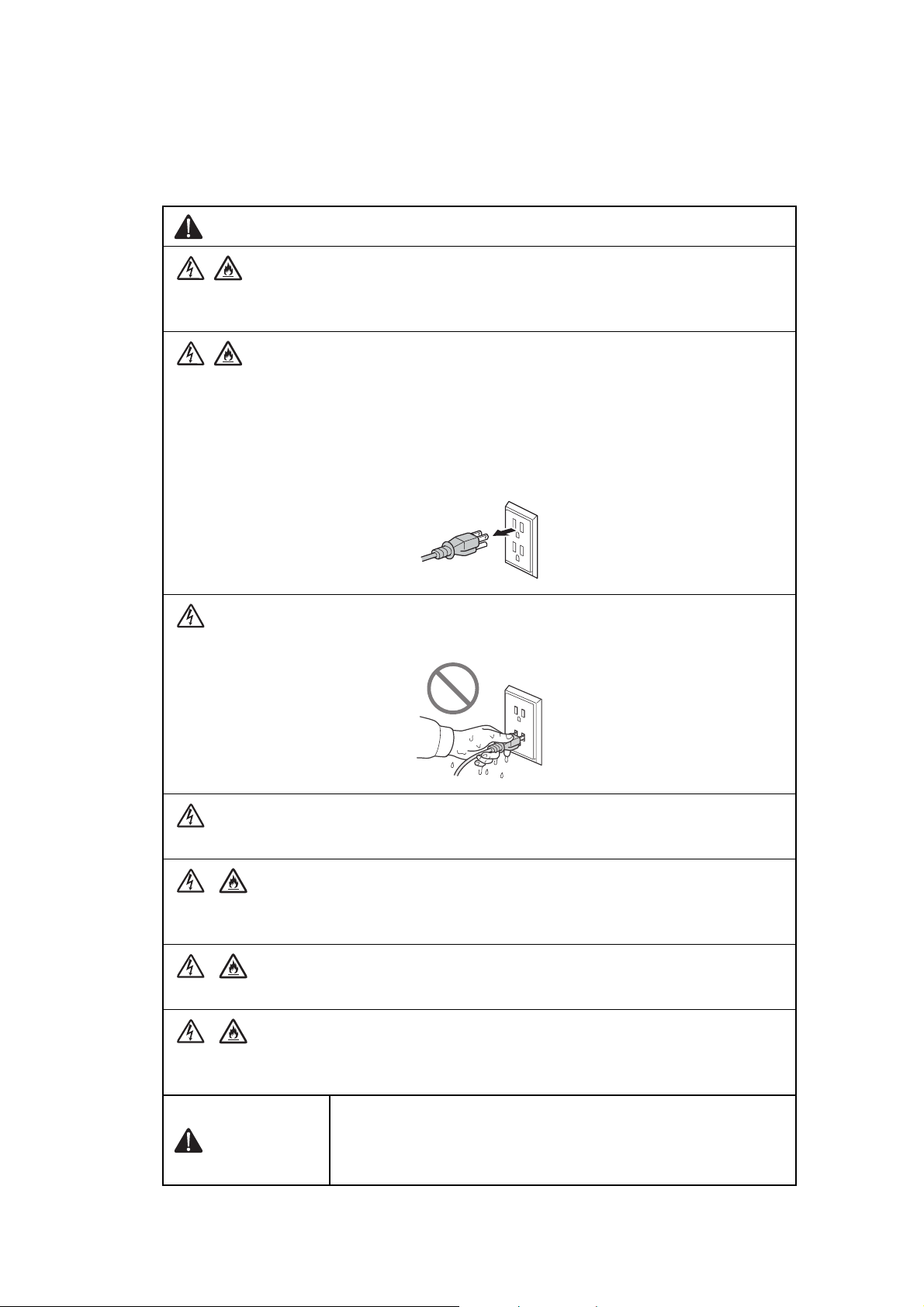
DO NOT handle the plug with wet hands.
DO NOT use this product during an electrical storm.
Always make sure the plug is fully inserted. DO NOT use the product or handle the cord if
the cord has become worn or frayed.
DO NOT allow this product to come into contact with water.
This product should be connected to an AC power source within the range indicated on
the rating label. DO NOT connect it to a DC power source or inverter.
WARNING
When removing the Low-voltage power supply, do not touch it
within 3 minutes after disconnecting the AC cord as it may cause
an electric shock due to the electric charge accumulated in the
capacitor.
vii
Confidential
Page 11
Power Cord Safety:
• This product is equipped with a 3-wire grounded plug. This plug will only fit into a
grounded power outlet. This is a safety feature. DO NOT attempt to defeat the purpose
of the grounded plug.
• DO NOT pull on the middle of the AC power cord; pulling on the middle may cause the
cord to separate from the plug. Doing this might cause an electrical shock.
• Only use the power cord supplied with this product (for certain models only).
• DO NOT use any undesignated cables (or optional devices). It may cause a fire or
injuries. Installation must be performed properly according to the user's guide.
• This product should be positioned so that nothing pinches or constricts the power cord.
• DO NOT allow anything to rest on the power cord.
• DO NOT place this product where people may step on the cord.
• DO NOT place this product in a position where the cord is stretched or strained, as it
may become worn or frayed.
• DO NOT use the product if the power cord is frayed or damaged. Doing so may cause
an electrical shock or fire.
• Brother strongly recommends that you DO NOT use any type of extension cord.
• DO NOT drop any metallic hardware or any type of liquid on the power plug of the
product. It may cause an electrical shock or a fire.
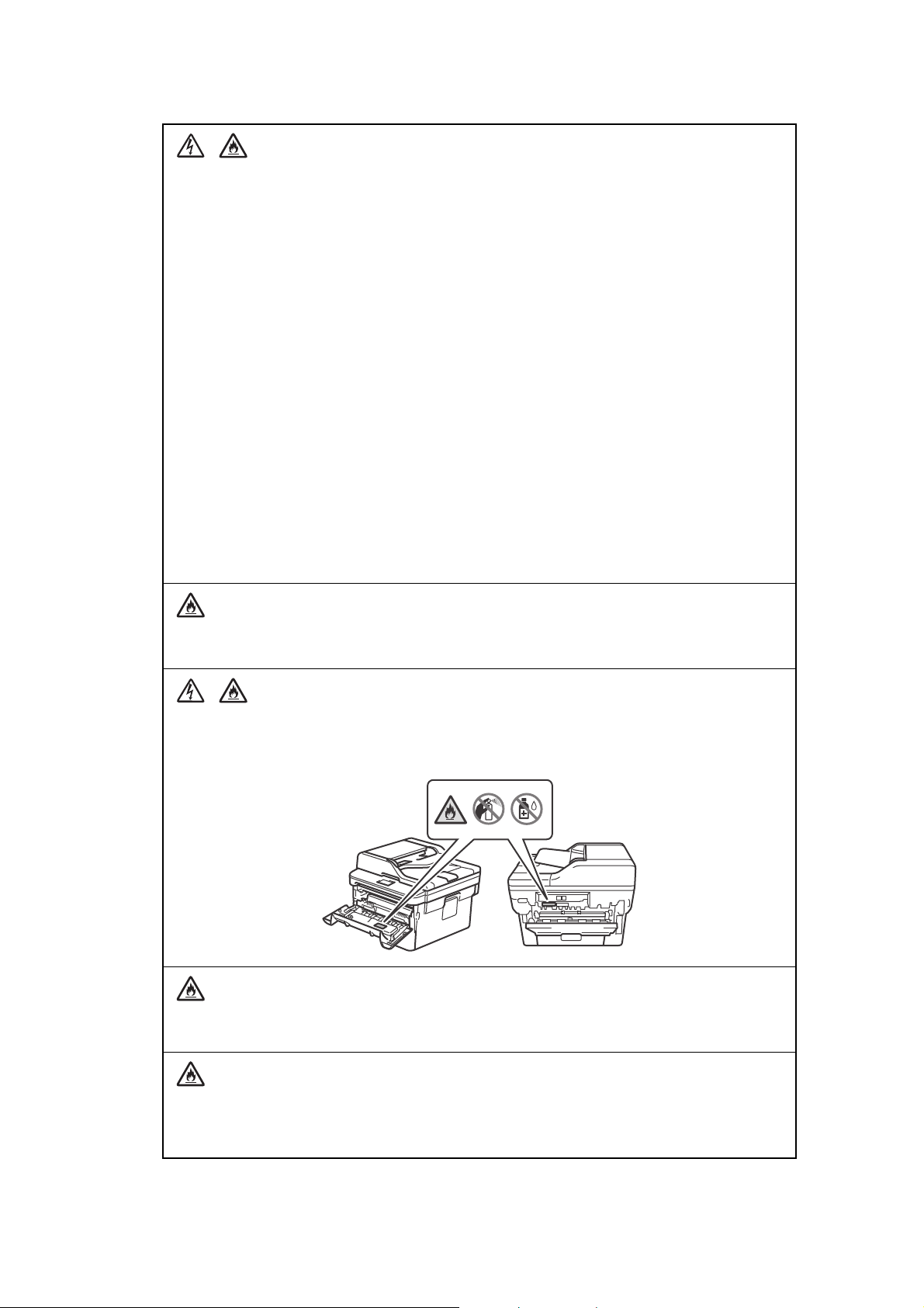
DO NOT put a toner cartridge or a toner cartridge and drum unit assembly into a fire. It
could explode, resulting in injuries.
DO NOT use flammable substances, any type of spray, or an organic solvent/liquid
containing alcohol or ammonia to clean the inside or outside of the product. Doing so
could cause a fire or electrical shock. Instead, use only a dry, lint-free cloth.
DO NOT attempt to operate this product when a paper jam or stray pieces of paper are
inside the product. Prolonged contact of the paper with the fuser unit could cause a fire.
DO NOT use a vacuum cleaner to clean up scattered toner. Doing this might cause the
toner dust to ignite inside the vacuum cleaner, potentially starting a fire. Carefully clean the
toner dust with a dry, lint-free soft cloth and dispose of it according to local regulations.
viii
Confidential
Page 12
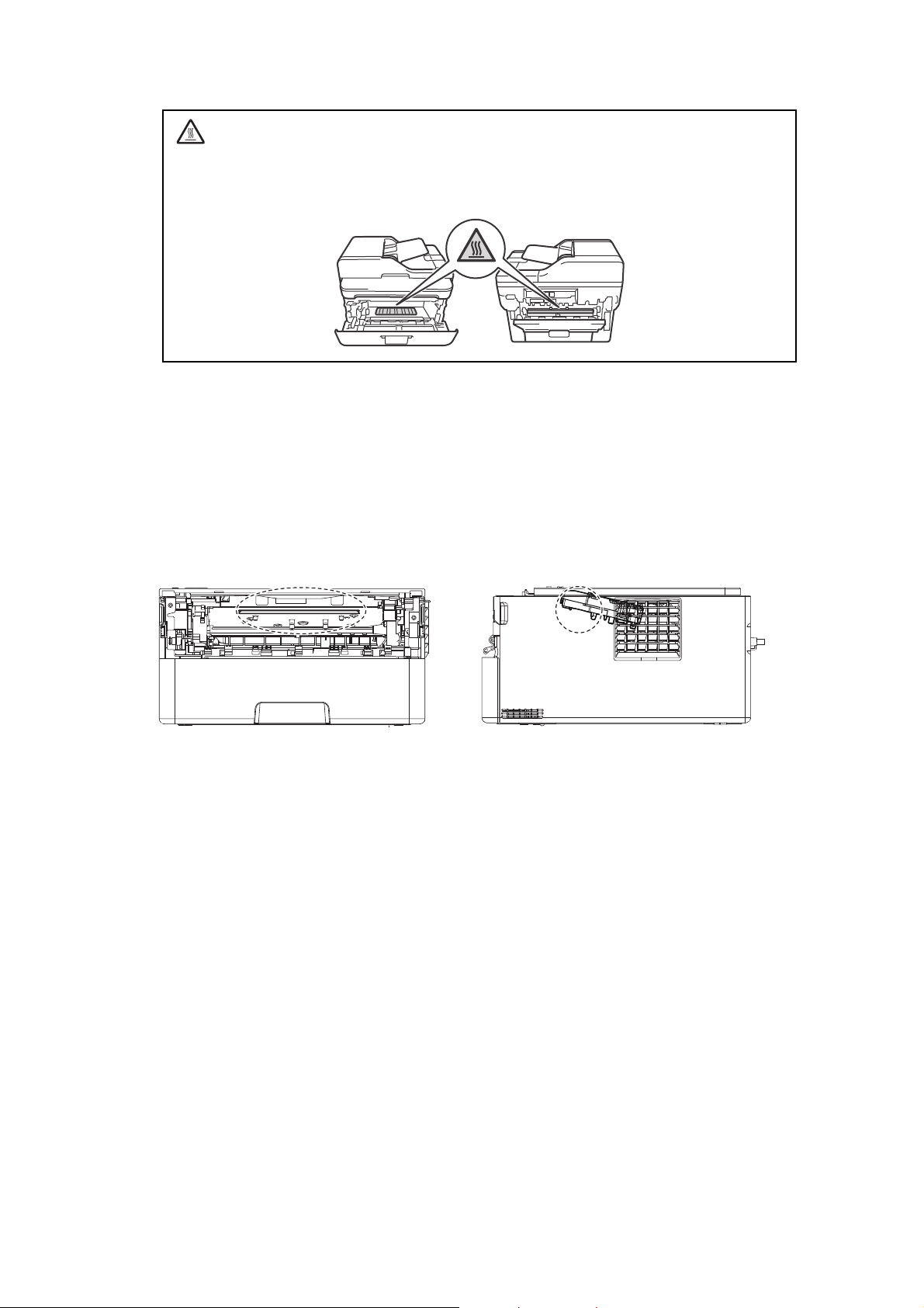
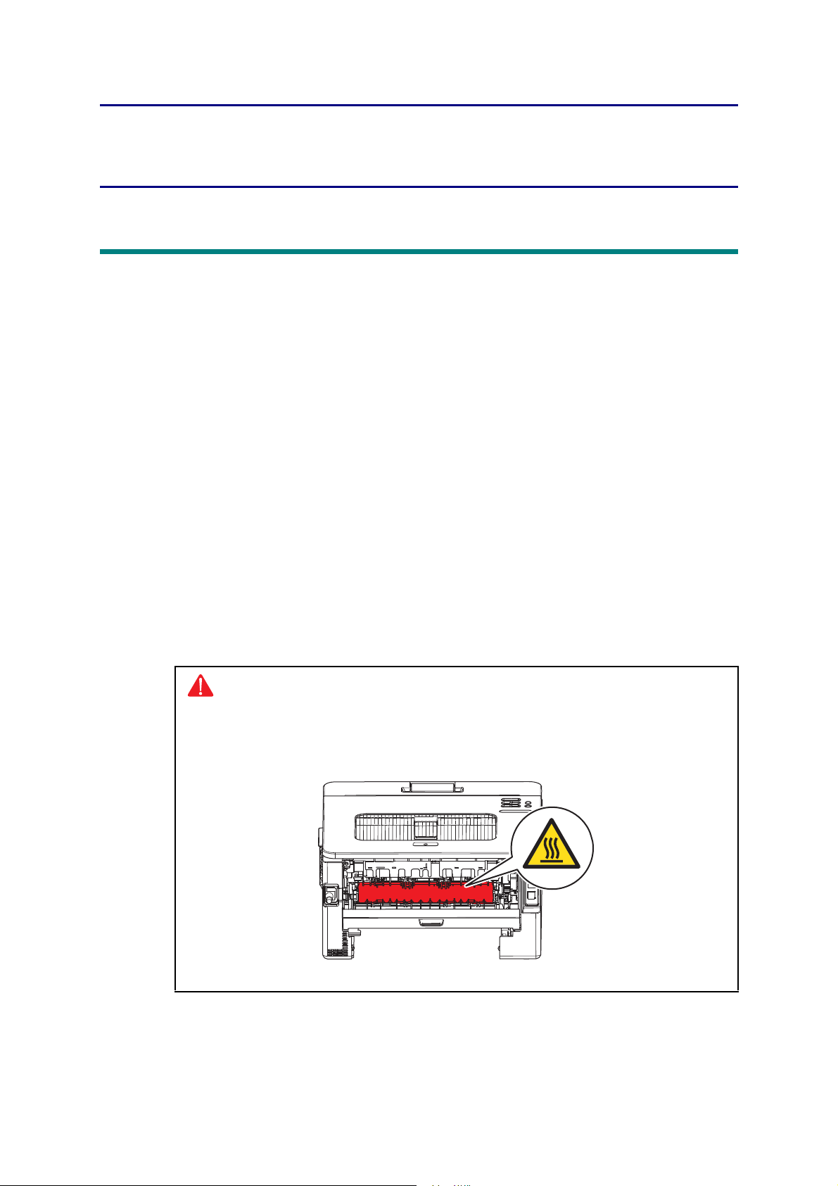
HOT SURFACE
<Location of the laser beam window>
Immediately after using the product, some internal parts of the product will be extremely
hot. Wait at least 10 minutes for the product to cool down before you touch the internal
parts of the product.
Caution for Laser Product (WARNHINWEIS für Laserdrucker)
CAUTION: In case of any trouble with the laser unit, replace the laser unit itself. To
prevent direct exposure to the laser beam, do not try to open the enclosure
of the laser unit.
ACHTUNG: Im Falle von Störungen der Lasereinheit muß diese ersetzt werden. Das
Gehäuse der Lasereinheit darf nicht geöffnet werden, da sonst
Laserstrahlen austreten können.
ix
Confidential
Page 13

Additional Information
When servicing the optical system of the machine, be careful not to place a screwdriver or
other reflective object in the path of the laser beam. Be sure to take off any personal
accessories such as watches and rings before working on the machine. A reflected beam,
though invisible, can permanently damage the eyes.
Since the beam is invisible, the following caution in print is attached on the laser unit.
x
Confidential
Page 14

CHAPTER 1 SUPPLEMENTAL
SPECIFICATIONS
1. GENERAL
The function comparative table for models as described in this Service Manual are shown below.
Model HL-2290 HL-2295D
Wired/
Wireless
LAN
Duplex
Printing
LCD Type
USB Host
(front)
USB Host
(rear)
NFC
PCL/PS
Paper
Input/
Standard
Tray
N/A N/A N/A N/A N/A N/A Wireless Wireless
N/A
LED LED LED LED LED LED
N/A N/A N/A N/A N/A N/A N/A N/A
N/A N/A N/A N/A N/A N/A N/A N/A
N/A N/A N/A N/A N/A N/A N/A N/A
N/A N/A N/A N/A N/A N/A N/A N/A
250 sheets 250 sheets 250 sheets 250 sheets 250 sheets 250 sheets 250 sheets 250 sheets
HL-L2310D
HL-L2312D
HL-L2330D
HL-L2331D
HL-L2335D
HL-L2336D
HL-B2000D
HL-L2350DW
HL-L2351DW
HL-L2352DW
16 characters
x
1 line
HL-L2357DW
16 characters
x
1 line
HL-L2370DN
Model
Wired/
Wireless
LAN
Duplex
Printing
LCD Type
USB Host
(front)
USB Host
(rear)
NFC
PCL/PS
Paper
Input/
Standard
Tray
Specifications are subject to change without notice.
HL-L2325DW
Wireless Wired Wired
HL-2590DN
16 characters
x
1 line
N/A N/A N/A N/A N/A N/A N/A
N/A N/A N/A N/A N/A N/A N/A
N/A N/A N/A N/A N/A N/A
N/A N/A
250 sheets 250 sheets 250 sheets 250 sheets 250 sheets 250 sheets 250 sheets
16 characters
x
1 line
HL-L2371DN
HL-L2372DN
16 characters
x
1 line
HL-L2370DW(XL)
HL-L2375DW
HL-L2376DW
Wired/
Wireless
16 characters
x
1 line
HL-B2050DN
Wired
16 characters
x
1 line
HL-B2080DW
Wired/
Wireless
16 characters
x
1 line
HL-L2385DW
HL-L2386DW
HL-2595DW
Wired/
Wireless
16 characters
x
1 line
1-1
Confidential
Page 15
Model HL-2290 HL-2295D
Warm-up
time
From Sleep
mode
From Power
OFF
ON
First print
time
From Ready
mode
From Sleep
mode
Printing speed (A4/Letter)
CPU
Dimensions
Carton size
(W x D x H)
Machine
size
Weights with Carton
without
Carton with
toner/drum
HL-L2310D
HL-L2312D
HL-L2330D
HL-L2331D
Less than 9 seconds at 73.4F / 50% (23°C / 50%)
Less than 26 seconds at 73.4F / 50% (23°C / 50%)
Less than 8.5 seconds at 73.4F (23°C)
Less than 17.5 seconds at 73.4F (23°C)
Up to 30/32 ppm
(Quiet Mode:
Up to 13/13 ppm)
Up to 28/28 ppm
(Engine spec:
Up to 30/32 ppm)
Up to 30/32 ppm
(Quiet Mode:
Up to 13/13 ppm)
(Quiet Mode:
Up to 13/13 ppm)
(for the USA)
Up to 30/32 ppm
(Quiet Mode:
Up to 13/13 ppm)
(except for the
USA)
600 MHz
444 x 449 x 366 mm
(17.5" x 17.7" x 14.4")
438 x 283 x 519 mm
(17.2" x 11.1" x 20.4")
356 x 360 x 183 mm
(14.0" x 14.2" x 7.2")
TBD TBD
8.3 kg / 18.2 lb
(for HL-L2310D)
8.5 kg / 18.7 lb
(for HL-L2312D)
8.3 kg / 18.2 lb
(HL-L2330D for
the USA)
TBD
(HL-L2330D for
Latin America,
and HL-L2331D)
TBD TBD
7.2 kg / 15.9 lb
7.2 kg / 15.9 lb
(HL-L2330D for
the USA)
HL-L2335D
HL-L2336D
Up to 34/36 ppm
(Quiet Mode:
Up to 13/13 ppm)
8.4 kg / 18.4 lb
(HL-L2335D for
Korea)
9.0 kg / 19.9 lb
(HL-L2335D for
Gulf)
TBD
(for HL-L2336D)
7.2 kg / 15.9 lb
(HL-L2335D for
Korea)
without
TBD TBD
Carton nor
toner/drum
Specifications are subject to change without notice.
1-2
6.3 kg / 13.9 lb
(for HL-L2310D)
6.1 kg / 13.4 lb
(for HL-L2312D)
TBD
(HL-L2330D for
Latin America,
and HL-L2331D)
7.4 kg / 16.3 lb
(HL-L2335D for
Gulf)
TBD
(for HL-L2336D)
6.3 kg / 13.9 lb
(HL-L2330D for
the USA)
TBD
(HL-L2330D for
Latin America,
and HL-L2331D)
6.3 kg / 13.9 lb
(HL-L2335D for
Korea)
6.1 kg / 13.4 lb
(HL-L2335D for
Gulf)
TBD
(for HL-L2336D)
Confidential
Page 16
Model HL-B2000D
Warm-up
time
First print
time
From Sleep
mode
From Power
OFF
ON
From Ready
mode
From Sleep
Less than 9 seconds at 73.4F / 50% (23°C / 50%)
Less than 26 seconds at 73.4F / 50% (23°C / 50%)
Less than 8.5 seconds at 73.4F (23°C)
Less than 17.5 seconds at 73.4F (23°C)
mode
Printing speed (A4/Letter)
Up to 34/36 ppm
(Quiet Mode:
Up to 13/13 ppm)
CPU
Dimensions
(W x D x H)
Carton size
600 MHz
444 x 449 x
366 mm
(17.5" x 17.7" x
14.4")
Machine size
356 x 360 x 183 mm (14.0" x 14.2" x 7.2")
Weights with Carton 9.0 kg / 19.9 lb
HL-L2350DW
HL-L2351DW
HL-L2357DW HL-L2325DW
HL-L2352DW
Up to 30/32 ppm
(Quiet Mode: Up to 13/13 ppm)
438 x 283 x 519 mm
(17.2" x 11.1" x 20.4")
8.3 kg / 18.2 lb
8.5 kg / 18.7 lb
(for HL-L2350DW)
HL-2590DN
Up to 24 ppm (LTR)
(Quiet Mode:
Up to 13 ppm)
Up to 34/36 ppm
(Quiet Mode:
Up to 13/13 ppm)
TBD TBD
without
Carton with
toner/drum
without
Carton nor
toner/drum
7.4 kg / 16.3 lb
6.5 kg / 14.3 lb
8.3 kg / 18.4 lb
(for HL-L2351DW)
8.5 kg / 18.7 lb
(for HL-L2352DW)
TBD
(for HLL2350DWR)
7.2 kg / 15.9 lb
(except for
HL-L2350DWR)
TBD
(for HLL2350DWR)
6.3 kg / 13.9 lb
(HL-L2350DW
for the USA, and
HL-L2351DW)
6.1 kg / 13.4 lb
(except for
HL-L2350DW
for the USA, and
HL-L2352DW)
7.2 kg / 15.9 lb
6.1 kg / 13.4 lb
TBD TBD
TBD TBD
TBD
(for HLL2350DWR)
Specifications are subject to change without notice.
1-3
Confidential
Page 17
Model
Warm-up
time
From Sleep
mode
From Power
ON
First print
time
OFF
From Ready
mode
From Sleep
mode
Printing speed (A4/Letter)
CPU
Dimensions
Carton size
(W x D x H)
HL-L2370DN
HL-L2371DN
HL-L2372DN
HL-L2370DW(XL)
HL-L2375DW
HL-L2376DW
HL-B2050DN HL-B2080DW
Less than 9 seconds at 73.4F / 50% (23°C / 50%)
Less than 26 seconds at 73.4F / 50% (23°C / 50%)
Less than 8.5 seconds at 73.4F (23°C)
Less than 17.5 seconds at 73.4F (23°C)
Up to 34/36 ppm
(Quiet Mode: Up to 13/13 ppm)
600 MHz
438 x 283 x
519 mm
(17.2" x 11.1" x
20.4")
438 x 283 x
519 mm
(17.2" x 11.1" x
20.4")
444 x 449 x 366 mm
(17.5" x 17.7" x 14.4")
(except for HLL2370DW(XL))
HL-L2385DW
HL-L2386DW
HL-2595DW
Less than 4
seconds at
73.4F / 50%
(23°C / 50%)
Less than 7
seconds at
73.4F (23°C) /
230V
Less than 11
seconds at
73.4F (23°C) /
230V
Machine
size
444 x 449 x
366 mm
(17.5" x 17.7" x
14.4")
(for HLL2370DW(XL))
356 x 360 x 183 mm
(14.0" x 14.2" x 7.2")
1-4
Confidential
Page 18

Model
Weights with Carton
HL-L2370DN
HL-L2371DN
HL-L2372DN
8.3 kg / 18.2 lb
(HL-L2370DN
for Europe and
HL-L2371DN for
Europe)
HL-L2370DW(XL)
HL-L2375DW
HL-L2376DW
8.3 kg / 18.2 lb
(HL-L2370DW for
the USA, and
except for
HL-L2375DW for
Asia)
8.5 kg / 18.7 lb
(for HL-
L2372DN)
TBD
(HL-L2370DW for
Latin America)
9.0 kg / 19.9 lb
(HL-L2370DN
for Asia)
9.3 kg / 20.5 lb
(for HL-
L2370DWXL)
TBD
(HL-L2370DN
for Russia and
HL-L2371DN for
9.0 kg / 19.9 lb
(HL-L2375DW for
Asia)
Asia)
8.4 kg / 18.4 lb
(for HL-
L2376DW)
without
Carton with
toner/drum
7.2 kg / 15.9 lb
(HL-L2370DN
for Europe,
HL-L2371DN for
Europe, and
HL-L2372DN)
7.2 kg / 15.9 lb
(HL-L2370DW for
the USA, except
for
HL-L2375DW for
Asia, and
HL-L2376DW)
7.4 kg / 16.3 lb
(HL-L2370DN
for Asia)
TBD
(HL-L2370DW for
Latin America)
TBD
(HL-L2370DN
for Russia and
HL-L2371DN for
7.8 kg / 17.1 lb
(for HL-
L2370DWXL)
Asia)
7.4 kg / 16.3 lb
(HL-L2375DW for
Asia)
without
Carton nor
toner/drum
6.1 kg / 13.4 lb
(HL-L2370DN
for Europe and
Asia, HLL2371DN for
Europe, and HL-
6.3 kg / 13.9 lb
(HL-L2370DW for
the USA,
HL-L2370DWXL
and HL-
L2376DW)
L2372DN)
TBD
TBD
(HL-L2370DN
(HL-L2370DW for
Latin America)
for Russia and
HL-L2371DN for
Asia)
6.1 kg / 13.4 lb
(for HL-
L2375DW)
Specifications are subject to change without notice.
HL-L2385DW
HL-B2050DN HL-B2080DW
HL-L2386DW
HL-2595DW
9.0 kg / 19.9 lb 9.2 kg / 20.2 lb
(for Europe)
TBD
(HL-L2385DW
for Oceania)
9.0 kg / 19.9 lb
(for Asia)
9.8 kg / 21.7 lb
(HL-L2385DW
for Asia)
9.5 kg / 21.0 lb
(for HLL2386DW)
8.3 kg / 18.3 lb
(for HL2595DW)
7.4 kg / 16.3 lb 7.4 kg / 16.3 lb TBD
(HL-L2385DW
for Oceania)
8.1 kg / 17.9 lb
(HL-L2385DW
for Asia)
7.9 kg / 17.4 lb
(for HLL2386DW and
HL-2595DW)
6.5 kg / 14.3 lb 6.3 kg / 13.9 lb
(for Europe)
TBD
(HL-L2385DW
for Oceania)
6.5 kg / 14.3 lb
(for Asia)
6.8 kg / 15.0 lb
(HL-L2385DW
for Asia)
7.0 kg / 15.4 lb
(for HLL2386DW and
HL-2595DW)
1-5
Confidential
Page 19
2. NETWORK CONNECTIVITY
Model HL-2290 HL-2295D
Wired
network
Wireless
network
Wired
network
Wireless
network
Wired
network
Wireless
network
Specifications are subject to change without notice.
Network
node type
Network
node type
Model HL-B2000D
Network
node type
Network
node type
Model
Network
node type
Network
node type
N/A
N/A
N/A NC-9300h
N/A NC-8800w N/A
HL-L2370DN
HL-L2371DN
HL-L2372DN
NC-9300h
N/A NC-8800w N/A NC-8800w
HL-L2350DW
HL-L2351DW
HL-L2352DW
HL-L2370DW(XL)
HL-L2375DW
HL-L2376DW
HL-L2310D
HL-L2312D
HL-L2357DW HL-L2325DW
HL-B2050DN
HL-L2330D
HL-L2331D
HL-B2080DW
HL-L2335D
HL-L2336D
HL-2590DN
HL-L2385DW
HL-L2386DW
HL-2595DW
3. SERVICE INFORMATION
Model All models
Machine life 50,000 pages (A4 / LTR) or 5 years
MTBF 4,000 hours
MTTR 0.5 hours
Maximum monthly volume Up to 15,000 pages
Maintenance
parts life
(Non-Periodical
Spare Parts)
Specifications are subject to change without notice.
Fuser unit 50,000 pages
Laser unit 50,000 pages
PF kit 1 50,000 pages
PF kit MP 50,000 pages
1-6
Confidential
Page 20

4. SUPPLIES
Model HL-2290 HL-2295D
Toner
cartridge
When printing A4/Letter size one-sided pages in accordance with ISO/IEC 19752
Shelf life: 2 years without opening (6 months after opening)
Drum unit Life expectancy: Approximately 12,000 pages (page/job)
The shelf life of toner cartridge and drum unit is guaranteed under the normal condition as below;
(Temperature) Normal condition: 0 to 40°C
* Storage condition at the temperature of 50°C: Up to 5 days
* Storage condition at the temperature of -20°C: Up to 5 days
(Humidity) Normal condition: 35 to 85%RH (without condensation)
* Storage condition at the humidity of 85 to 95%RH: Up to 5 days (without condensation)
* Storage condition at the humidity of 10 to 35%RH: Up to 5 days (without condensation)
*1
Toner supplied with the machine.
Specifications are subject to change without notice.
Starter
toner
Standard
toner
High
capacity
toner
Super
high
capacity
toner
Ultra high
capacity
toner
Approximately 3,000 pages
*1
Approximately 1,200 pages
Approximately 3,000 pages
N/A
N/A
The life expectancy varies according to the use condition.
Shelf life: 2 years
HL-L2310D
HL-L2312D
Approximately
700 pages
Approximately
4,500 pages
(for the USA and
Europe)
N/A
(for Russia and
Oceania)
HL-L2330D
HL-L2331D
Approximately
700 pages
(for HL-L2330D)
Approximately
3,000 pages
(HL-L2331D for
India)
Approximately
1,200 pages
(for HL-L2330D)
N/A
(for HL-L2331D)
Approximately
4,500 pages
HL-L2335D
HL-L2336D
Approximately
1,200 pages
(HL-L2335D for
Asia)
Approximately
3,000 pages
(HL-L2335D for
Gulf and
Philippines)
Approximately
700 pages
(HL-L2335D for
Ta iw a n)
Approximately
3,000 pages
(HL-L2336D for
Vietnam /
Indonesia)
Approximately
1,200 pages
Approximately
4,500 pages
(for HL-L2335D)
N/A
(for HL-L2336D)
1-7
Confidential
Page 21
HL-L2350DW
Model HL-B2000D
HL-L2351DW
HL-L2357DW HL-L2325DW HL-2590DN
HL-L2352DW
Toner
cartridge
Starter
toner
Approximately
*1
2,600 pages
Approximately
700 pages
Approximately
1,200 pages
Approximately
700 pages
Approximately
3,000 pages
(except for HLL2351DW)
Approximately
3,000 pages
(for HLL2351DW)
Standard
toner
N/A
Approximately
1,200 pages
Approximately 1,200 pages
(except for HLL2351DW)
N/A
(for HLL2351DW)
High
N/A Approximately 3,000 pages
capacity
toner
Super
high
capacity
toner
N/A
Approximately
4,500 pages
(except for HLL2350DW for
Approximately 4,500 pages N/A
Russia and
Oceania)
N/A
(HL-L2350DW
for Russia and
Oceania)
Ultra high
N/A
capacity
toner
When printing A4/Letter size one-sided pages in accordance with ISO/IEC 19752
Shelf life: 2 years without opening (6 months after opening)
Drum unit Life expectancy: Approximately 12,000 pages (page/job)
The life expectancy varies according to the use condition.
Shelf life: 2 years
The shelf life of toner cartridge and drum unit is guaranteed under the normal condition as below;
(Temperature) Normal condition: 0 to 40°C
* Storage condition at the temperature of 50°C: Up to 5 days
* Storage condition at the temperature of -20°C: Up to 5 days
(Humidity) Normal condition: 35 to 85%RH (without condensation)
* Storage condition at the humidity of 85 to 95%RH: Up to 5 days (without condensation)
* Storage condition at the humidity of 10 to 35%RH: Up to 5 days (without condensation)
*1
Toner supplied with the machine.
Specifications are subject to change without notice.
1-8
Confidential
Page 22

Toner
cartridge
Model
Starter
toner
HL-L2370DN
HL-L2371DN
HL-L2372DN
Approximately
*1
4,500 pages
(HL-L2371DN for
Europe)
N/A
(HL-L2371DN for
Asia)
Approximately
700 pages
(HL-L2370DN for
Europe and
Russia, and
HL-L2372DN)
Approximately
1,200 pages
(HL-L2370DN for
Asia)
Approximately
HL-L2370DW(XL)
HL-L2375DW
HL-L2376DW
Approximately 700 pages
(for HL-2370DW)
Approximately 7,500 pages
(for HL-2370DW(XL))
Approximately 1,200 pages
(HL-L2375DW for Europe,
Russia and Asia)
Approximately 700 pages
(HL-2370DW for Oceania)
Approximately 3,000 pages
(HL-L2375DW for Gulf,
Korea and Philippines)
Approximately 700 pages
(HL-L2375DW for Taiwan)
N/A
(for HL-L2376DW)
HL-B2050DN
HL-B2080DW
Approximately
2,600 pages
HL-L2385DW
HL-L2386DW
HL-2595DW
Approximately
700 pages
(HL-L2385DW for
Oceania)
Approximately
3,000 pages
(HL-L2385DW for
Asia)
Approximately
4,500 pages
(HL-L2385DW for
Korea and
Philippines)
N/A
(for HL-L2386DW)
Approximately
3,000 pages
(for HL-2595DW)
3,000 pages (HLL2370DN for
Korea)
Standard
toner
Approximately
1,200 pages
Approximately 1,200
pages
N/A
Approximately
1,200 pages
(except for HLL2371DN)
N/A
(for HL-L2371DN)
High
capacity
Approximately 3,000 pages
N/A
Approximately
3,000 pages
toner
Super
high
capacity
toner
Approximately
4,500 pages
(except for HLL2370DN for
Russia)
N/A
Approximately 4,500 pages
(except for HL-L2375DW for
Oceania and Russia)
N/A
(HL-L2375DW for Oceania
and Russia)
N/A
Approximately
4,500 pages
(HL-L2370DN for
Russia)
Ultra high
N/A
capacity
toner
When printing A4/Letter size one-sided pages in accordance with ISO/IEC 19752
Shelf life: 2 years without opening (6 months after opening)
Drum unit Life expectancy: Approximately 12,000 pages (page/job)
The life expectancy varies according to the use condition.
Shelf life: 2 years
The shelf life of toner cartridge and drum unit is guaranteed under the normal condition as below;
(Temperature) Normal condition: 0 to 40°C
* Storage condition at the temperature of 50°C: Up to 5 days
* Storage condition at the temperature of -20°C: Up to 5 days
(Humidity) Normal condition: 35 to 85%RH (without condensation)
* Storage condition at the humidity of 85 to 95%RH: Up to 5 days (without condensation)
* Storage condition at the humidity of 10 to 35%RH: Up to 5 days (without condensation)
*1
Toner supplied with the machine.
Specifications are subject to change without notice.
1-9
Confidential
Page 23
CHAPTER 2 ERROR INDICATIONS AND
TROUBLESHOOTING
1. INTRODUCTION
Troubleshooting is the countermeasure procedures that the service personnel should follow if
an error or malfunction occurs with the machine. It is impossible to anticipate all of the possible
troubles which may occur in future and determine the troubleshooting procedures, so this
chapter covers some sample troubles. However, those samples will help the service personnel
pinpoint and repair other defective elements.
1.1 Precautions
Be sure to observe and follow all the precautions to prevent any secondary problems from
happening during troubleshooting.
(1) Always turn OFF the power and unplug the power cable before removing any covers or
PCBs, adjusting the machine and so on. If you need to take voltage measurements with the
power switched on, take the greatest of care not to receive an electric shock.
(2) When connecting or disconnecting cable connectors, make sure that you hold the
connector body and not the cables.
(3) Static electricity charged in your body may damage electronic parts. Before handling the
PCBs, touch a metal portion of the machine to discharge static electricity charged in your
body. When transporting PCBs, be sure to wrap them in conductive sheets.
When replacing the PCBs, put on a grounding wrist band and perform the job on an
antistatic mat. Also take care not to touch the conductor sections on the flat cables.
(4) Follow the warning by all means.
Warning
Hazard labels as shown below are attached to the machine. Fully understand the
descriptions on the hazard labels and observe them during troubleshooting.
Take extreme care not to remove or damage the hazard labels.
2-1
Confidential
Page 24

Warning
DO NOT use any flammable spray or flammable solvent such as alcohol,
benzine, or thinner in or around the machine. Otherwise a fire or electric shock
may result.
(5) Check again that the portions and parts repaired or removed during the repair work
function properly when the repair is completed.
A certain interface or function could be set to invalid to serve the needs of customers. Ask sales
representative if this is the case before performing the check.
2-2
Confidential
Page 25

1.2 Checks before Commencing Troubleshooting
Check the following items before attempting to repair the machine.
Operating environment
(1) The machine is placed on a flat, stable surface.
(2) The machine is used in a clean environment where the temperature is between 10°C
(50°F) and 32°C (89.6°F) and the relative humidity is maintained between 20% and 80%.
(3) Ensure the machine is not exposed to direct sunlight, excessive heat, moisture, or dust.
(4) Keep the machine horizontal when you carry it. To prevent injuries when moving or lifting
this machine, make sure to use at least two people.
Power supply
(1) The AC input power supply described on the rating plate of the machine should be within
±10% of the rated voltage.
(2) The AC input power supply is within the regulated value.
(3) The cables and harnesses are connected correctly.
(4) The fuses are not blown.
Paper
(1) A recommended type of paper is being used.
(2) The paper is not damp.
(3) The paper is not short-grained paper or acid paper.
Consumable parts
(1) The drum unit (including the toner cartridge and toner box) is installed correctly.
Others
(1) Condensation
When the machine is moved from a cold place into a warm room, condensation may occur
inside the machine, causing various problems as listed below.
• Condensation on the surface of optical devices such as the lens, reflecting mirror, and
protection glass, etc., may cause light print image.
• If the exposure drum is cold, the electrical resistance of the photosensitive layer is
increased, making it impossible to obtain the correct contrast when printing.
• Condensation on the charge unit may cause corona charge leakage.
• Condensation on the plate and separation pad may cause paper feed problems.
If condensation has occurred, leave the machine for at least two hours to allow it to reach
room temperature.
If the drum unit is unpacked soon after it is moved to a warm room from a cold location,
condensation may occur inside the unit which may cause printing failure. Leave the drum
unit for one or two hours until it reaches room temperature, and then unpack it.
(2) Low temperature
The motor may not drive normally under the low temperature environment. This is due to
there being too much load to drive each unit. In this case, increase the room temperature.
2-3
Confidential
Page 26

Cleaning
Use a soft dry lint-free cloth.
Warning
DO NOT use any flammable spray or flammable solvent such as alcohol, benzine,
or thinner to clean the machine. DO NOT use these articles near the machine.
2-4
Confidential
Page 27
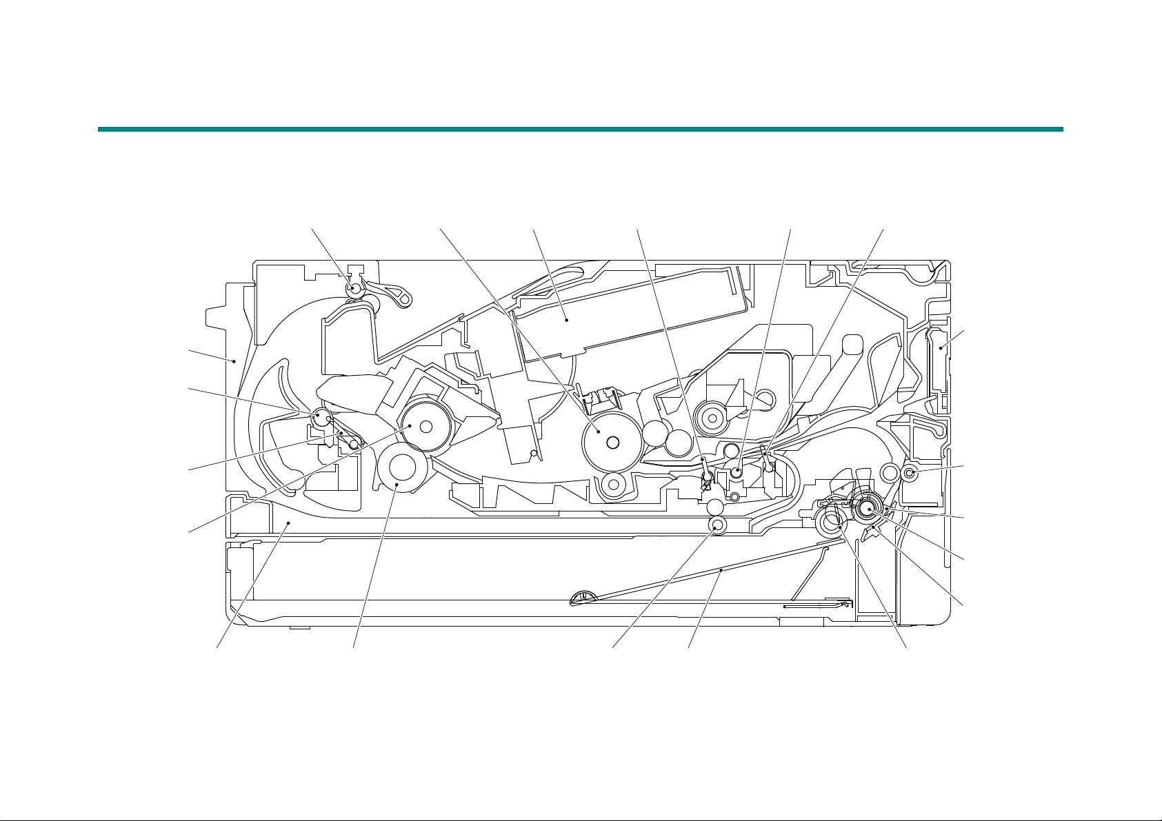
2. OVERVIEW
<Back side>
Eject roller 2 Exposure drum Laser unit Registration rear actuator
<Front side>
Registration front actuator
Manual feed
slot
Paper dust
cleaning roller
Paper feed
actuator
Paper pick up rollerPlateDuplex paper feed rollerPressure rollerDuplex tray
Heat roller
Back cover
Registration roller
Separation
roller
Separation
pad
Eject actuator
Eject roller 1
2.1 Cross-section Drawing
Manual feed slot models
Fig. 2-1
2-5
Confidential
Page 28
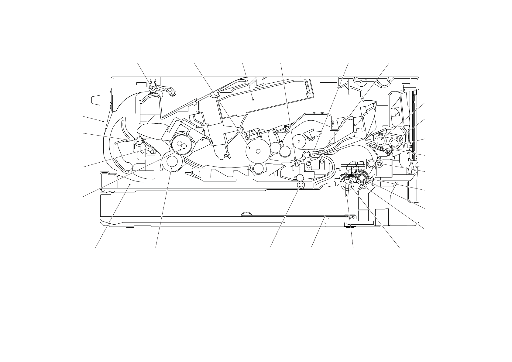
MP models
Eject roller 2 Exposure drum Laser unit Registration rear actuator Registration front actuator
MP separation
roller
Paper dust
cleaning roller
Paper feed
actuator
Paper pick up rollerPaper empty actuatorPlateDuplex paper feed rollerPressure rollerDuplex tray
Heat roller
Back cover
Registration roller
Separation
roller
Separation
pad
Eject actuator
Eject roller 1
MP paper empty
actuator
MP paper pick-up
roller
MP separation pad
<Back side> <Front side>
Fig. 2-2
2-6
Confidential
Page 29
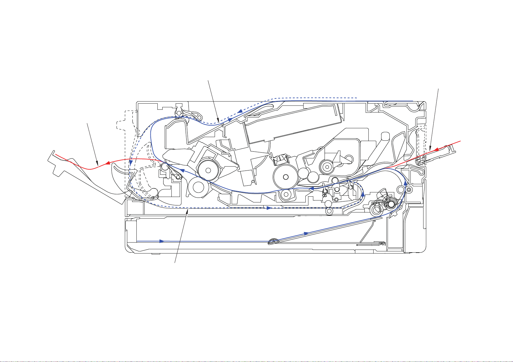
2.2 Paper Feeding
Eject to output tray
Feed from
manual feed slot
Duplex path
Eject to back side
<Back side> <Front side>
Manual feed slot models
Fig. 2-3
2-7
Confidential
Page 30
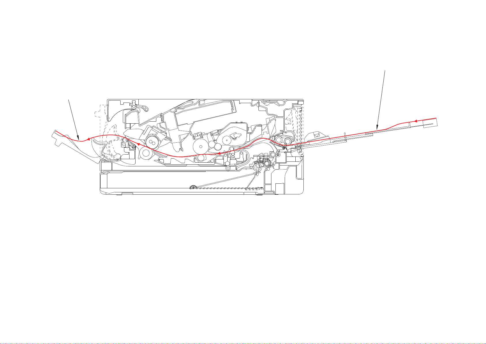
MP models
Feed from MP tray
Eject to back side
<Back side> <Front side>
Fig. 2-4
2-8
Confidential
Page 31

2.3 Operation of Each Part and Location of Parts
Part name Operation
Paper pick up roller
Separation roller,
Separation pad
Paper feed actuator
(Paper feed sensor)
Registration front actuator
(Registration front sensor)
Registration roller Corrects the paper alignment when the paper makes
Registration rear actuator
(Registration rear sensor)
Heat roller,
Pressure roller
Eject actuator
(Eject sensor)
Feeds the paper to the separation roller from the paper tray.
Separates paper fed from the paper tray into single sheets.
Detects paper trays (open / closed).
Detects paper jams in paper trays.
Determines whether paper is fed from the paper tray.
Detects the front edge of the paper to control the
registration roller drive.
Detects paper jams in the front section of the machine.
Determines whether paper is fed from the paper tray.
contact with the stopped registration roller. After the
correction, it rotates to feed the paper to the process.
Detects paper pass and adjusts the writing start position for
the paper.
Detects paper jams in the front or center section of the
machine.
Detects the rear edge of the paper to determine the paper
size.
Fuses the toner transferred to paper by heat and pressure,
and feeds paper to the eject roller 1.
Detect whether or not paper is ejected from the fuser unit.
In the case of the 2-sided printing, detect the rear edge of
paper and adjust the timing of the eject roller 2 switching.
Detects paper jam in the rear section of the machine.
Detects open fuser cover.
Eject roller 1 Feeds the paper ejected from the fuser unit to eject roller 2.
Eject roller 2 Eject the paper to the face-down output tray. In the case of
the 2-sided printing, after the front of the sheet is printed
and the paper is fed up to a certain point, eject roller 2
rotates conversely, and the paper is fed to the duplex tray.
Duplex paper feed roller Feeds the paper passing through the duplex tray to the
registration roller.
Front cover sensor Detects open / closed front cover.
Paper empty actuator Detects the paper in the paper tray 1.
Detects paper jams in the paper tray 1.
MP paper pick-up roller Feeds paper from the MP tray to the MP separation roller.
MP separation roller,
MP separation pad
MP paper empty actuator
(MP paper empty sensor)
Back cover/duplex tray sensor Detects open / closed back cover or the duplex tray is set.
New toner sensor When exchange to the new toner cartridge, detects the
Toner sensor Detects the toner cartridge is set.
Separates the paper fed from the MP tray into single
sheets.
Detects the paper in the MP tray.
Detects paper jams in the MP tray.
kinds of toner and add 1 to the reset of the developing bias
and to the exchange count.
2-9
Confidential
Page 32

Part name Operation
T1 clutch
New toner sensor PCB ASSY
Registration clutch
Registration rear sensor
Registration
front sensor
Paper feed sensor PCB ASSY
Toner box solenoid
*1
Eject sensor PCB ASSY
Back cover/duplex
tray sensor
Front cover sensor
Toner box new PCB ASSY
*1
Toner sensor
PCB ASSY
*1
*1
: For models with Toner box
*2
: For models without Toner box
Relay PCB ASSY*1
*2
External temperature/humidity
sensor
Detects external temperature and humidity around the
machine.
Pickup clutch Drives the pick up roller at the timing of paper feeding.
Registration clutch Controls the activation of the registration roller for the paper
alignment adjustment.
MP solenoid Presses the MP paper pick-up roller against the paper
when feeding from the MP tray.
Location of sensors and clutches
Fig. 2-5
2-10
Confidential
Page 33

2.4 Block Diagram
Wireless LAN PCB
NFC PCB
Toner box model only
Toner box solenoid
New toner box sensor
PCB
New toner sensor PCB
MP model only
MP solenoid
MP paper empty
sensor PCB
T1 paper empty/paper feed sensor PCB
T1 paper empty sensor
T1 paper feed sensor
Manual feed slot model only
T1 paper feed sensor
T1 paper feed sensor
Relay PCB
Relay PCB
PCB
Main PCB
LED model only
Panel PCB
LCD model only
Panel PCB
LCD
High-voltage
power supply
PCB
Toner box
model only
New toner
sensor
light emission
New toner
box sensor
light emission
Front cover sensor
Cartridge sensor model only
Cartridge sensor
Laser unit PCB
Fan
New toner sensor PCB
Registration front/rear
sensor PCB
Laser unit
Back cover/duplex tray
sensor
Fuser unit
Center thermistor
Side thermistor
Main heater
MP model only
Sub heater
Eject
sensor PCB
Eject sensor
Low-voltage
power supply
PCB
Polygon motor
Paper feed motor
Registration clutch
T1 clutch
Fig. 2-6
2-11
Confidential
Page 34

Side cover R
Back cover
Low-voltage power
supply PCB ASSY
Registration front/rear
actuator holder ASSY
Paper feed sensor PCB ASSY
Front cover ASSY
Paper tray
Side cover L
T1 clutch
Registration clutch
Fan
Laser unit
Inner chute ASSY
Outer chute ASSY
Fuser unit
Main shield plate
Main PCB ASSY
Motor drive sub
ASSY
Duplex tray
Paper feed motor
Fuser gear
64R/36R
Eject sensor
PCB ASSY
New toner sensor PCB ASSY
High-voltage power
supply PCB ASSY
Fuser cover
Toner
cartridge
Drum unit
Top cover ASSY
2.5 Main Components
Fig. 2-7
2-12
Confidential
Page 35

3. ERROR INDICATIONS
This machine includes a self-diagnosis function. If the machine does not work normally it judges
that an error has occurred, and indicates the corresponding error message on the LCD, which
in turn helps the service personnel to quickly find out the problem.
3.1 Error Codes
The shaded errors hardly occur under normal use. They may be caused by noise around the
installation site, variation in power supply voltage, or software failure.
Error
Codes
0101 --- 050A
ASIC error or motor driver error
0102
occurred.
Cannot detect the synchronized signal
of the paper feed motor. The speed of
0201
the paper feed motor does not stabilize
within the specified time.
0202 ---
0203 ---
Cannot detect the lock signal of the
0300
polygon motor for the laser unit.
(second time)
Cannot detect the lock signal of the
0305
polygon motor for the laser unit. (first time)
0401 BD sensor failure (second time) 2-34 0900
0402 --- 0A01 ---
0405 BD sensor failure (first time) 2-34 0A02 Detected a fan failure. 2-36
The center thermistor of the fuser unit
0501
has not reached the specified
temperature within the specified time.
The center thermistor of the fuser unit has
not reached the specified temperature
0502
within the specified time after it was
heated normally to the certain level.
The center thermistor of the fuser unit
0503
detected a temperature higher than the
specified value.
After the heat unit was heated normally, the
0504
center thermistor of the fuser unit detected a
temperature lower than the specified value.
The center thermistor of the fuser unit
detected a temperature rise greater than
0505
the specified value within the specified time.
The center thermistor of the fuser unit
detected a temperature fall greater than the
0506
specified value within the specified time.
Temperature of the end part didn’t rise by 1
0508
°C when the fuser unit heater was turned ON.
Description
Refer
2-33 050B
2-33 050C
2-33 050F ---
2-33 0800 ---
2-35
2-35 0B01
2-35 0B02
2-35 0C00 ---
2-35 0D01 ---
2-35 0D02 ---
2-35 0D03 ---
to:
Error
Codes
The hardware detected a temperature
error through the center thermistor or
the side thermistor of the fuser unit.
When the center thermistor of the fuser unit
was lower than the idle temperature, the
side thermistor detected a temperature
higher than the specified temperature.
When the center thermistor of the fuser unit
was higher than the idle temperature, the
side thermistor detected a temperature
lower than the specified temperature.
050D ---
Detected irregular power supply for
more than 100 times.
0A03 ---
An error occurred in the high-voltage
power supply PCB ASSY while
operating.
An error occurred in the high-voltage
power supply PCB ASSY when the
machine was in the ready state.
Description
Refer
to:
2-35
2-35
2-35
2-36
2-37
2-37
2-13
Confidential
Page 36

Error
Codes
Description
Refer
to:
Error
Codes
Toner cartridge could not
0D04 --- 2500
communicate with the cartridge
sensor.
0E00 --- 2501 ---
1003 --- 2502 ---
1004 --- 2503 ---
110 0 --- 2601 ---
1200 --- 2602 ---
1300 --- 2603 ---
1400 --- 2604 ---
1500 --- 2605 ---
1701 --- 2701 ---
1801 --- 2702 ---
1802 --- 2703 ---
1803 --- 2801 ---
1808 --- 2802 ---
1901 --- 2803 ---
1A01 --- 2804 ---
1B01 --- 2805 ---
1C00 --- 2806 ---
1D01 --- 2901 ---
1D02 --- 2902 ---
1D03 --- 2903 ---
1D04 --- 2904 ---
1E01 --- 2905 ---
1E02 --- 2906 ---
1F00 --- 2A01 ---
1F02 --- 2A02 ---
2000 --- 2A03 ---
2001 --- 2A04 ---
2002 --- 2A05 ---
2003 --- 2B01 ---
2100 --- 2B02 ---
2101 --- 2C01 ---
2102 --- 2C02 ---
2103 --- 2D01 ---
Cartridge sensor detected that the
2200
incompatible toner cartridge was
installed.
2-37 2E00
Could not communicate with the
cartridge sensor on the machine side.
2201 --- 2E01 ---
2202 --- 2E03 ---
2203 --- 2F01 ---
Toner cartridge is not recognized by
2400
the cartridge sensor.
2-37 2F03 ---
2401 --- 3001 ---
2402 --- 3002 ---
2403 --- 3003 ---
Description
Refer
to:
2-37
2-37
2-14
Confidential
Page 37

Error
Codes
Description
Refer
to:
Error
Codes
3102 --- 4900 ---
3202 --- 4A00 ---
3301 --- 4B01
3302 --- 4B02 ---
3401 --- 4B03 ---
3402 --- 4B04 ---
3501 --- 4B06
3601 --- 4C01
3701 --- 4C02 ---
3702 --- 4C03 ---
3703 --- 4C04 ---
3801 --- 4C05 ---
3802 --- 4C06
3900 --- 4D01
A communication error occurred
3A00
between the controller and engine in
2-37 4E01
main PCB.
Number of the drum unit rotations
4000
reaches the upper limit soon.
2-38 4F01
4001 --- 4F02
4002 --- 4F03
4003 --- 4F04
4004 --- 4F05
Number of the drum unit rotations has
4200
reached the upper limit.
2-38
5001
4201 --- 5002
4202 --- 5003
4203 --- 5004
4204 --- 5005
4209 --- 5006
4300 --- 5100 ---
4400 --- 5200 ---
4500 --- 5301 ---
4600 --- 5302 ---
4700 --- 5401 ---
4800 --- 5402 ---
Description
Dot counter of the toner cartridge or
develop roller counter reaches the
upper limit soon.
The amount of toner supplied of the
toner box reaches the upper limit soon.
Dot count or develop roller counter of
the toner cartridge in models without
toner box has reached the upper limit
in the toner stop mode.
The amount of toner supplied of the
toner box has reached the upper limit.
Dot count or develop roller counter of
the toner cartridge in models without
toner box is reaching the upper limit in
the continuous printing mode.
Toner cartridge in models without toner
box has reached the upper limit in the
continuous printing mode.
The new toner sensor of the toner
cartridge could not detect a new
cartridge properly.
New process sensor could not detect
the new drum unit correctly.
Refer
to:
2-38
2-38
2-38
2-38
2-38
2-38
2-39
2-39
2-15
Confidential
Page 38

Error
Codes
Description
Refer
to:
Error
Codes
5406 --- 6300 ---
5502 --- 6400 ---
5602 --- 6602 ---
5702 --- 6701 ---
The side thermistor detected a
5801 --- 6801
temperature higher than the specified
value.
5802 --- 6802 ---
Some fuser unit errors occurred at
5902 --- 6901
power-ON or upon recovery from sleep
mode.
After the error was detected at the
fuser unit, power was turned ON again
5A02 --- 6902
and the error is being checked. (If
power is turned OFF and ON after
error code 6901 occurred, this code is
displayed for about 15 minutes.)
Electric discharge that may be caused
5B02 --- 6A00
by dirt on the corona wire of the drum
unit was detected.
5C02 --- 6B01 ---
5D02 --- 6B02 ---
New toner box sensor could not detect
5E00
the new toner box correctly.
The front cover sensor detected that
6001
the front cover was open.
2-39 6B03 ---
2-40 6B04 ---
6002 --- 6B0A ---
6003 --- 6C01 ---
The eject sensor detected that the
6004
fuser cover was open.
2-40 6C02 ---
6007 --- 6C03 ---
The new toner sensor detected that no
6101
toner cartridge was set.
2-41 6C04 ---
6102 --- 6D00 ---
6103 --- 6E00 ---
6104 --- 6F00
The new toner box sensor detected
6106
that no toner box was set.
Detected that the drum unit was not set
6200
by detecting the electrodes current.
2-41 7000
2-41
Detected that supply power is
unstable. (less than 100 times)
After the registration rear sensor
detects paper pass, the eject sensor
does not detect paper pass.
7001 ---
6201 --- 7002 ---
6202 --- 7003 ---
6203 --- 7004 ---
After the registration rear sensor
detects the end of paper pass and the
6204 --- 7100
specified period of time has passed,
the eject sensor continues to detect
paper pass.
6208 --- 7101 ---
6209 --- 7102 ---
620A --- 7103 ---
Description
Refer
to:
2-43
2-43
2-43
2-44
2-44
2-44
2-45
2-16
Confidential
Page 39

Error
Codes
Description
Refer
to:
Error
Codes
7104 --- 8100 ---
7105 --- 8401 ---
7106 --- 8402 ---
When the paper is fed from the MP
tray, after the MP paper empty sensor
detects paper pass, the registration
7200
2-45 8403 ---
rear sensor does not detect paper pass
after a set period of time.
7300 --- 8501 ---
7301 --- 8502 ---
When printing from the paper tray, the
registration front sensor does not
7302
detect paper pass within the specified
2-46 8503 ---
time after the T1 paper feed sensor
detected paper pass.
7400 --- 8504 ---
7401 --- 8505 ---
7402 --- 8506 ---
7500 --- 8507 ---
7501 --- 8508 ---
7502 --- 8601 ---
7601 --- 8602 ---
7602 --- 8603 ---
7701 --- 8604 ---
7702 --- 8701 ---
After the first side is printed in 2-sided
printing mode, the registration front
7800
sensor does not detect paper pass
2-46 8702 ---
after a set period of time.
7801 --- 8703 ---
7802 --- 8708 ---
7803 --- 8709 ---
7804 --- 870A ---
7805 --- 870B ---
7900 --- 870C ---
7A01 --- 870D ---
7A02 --- 870E ---
7B01 --- 870F ---
7B02 --- 8801 ---
7B03 --- 8802 ---
7B04 --- 8808 ---
7B05 --- 8809 ---
7C00 --- 880A ---
7D00 --- 8901 ---
7E00 --- 8902 ---
The back cover sensor detected the
7F00 --- 8903
open state when 2-sided printing is
started (before the registration of
printing in the engine).
The back cover sensor detected the
8000 --- 8904
open state during 2-sided printing
(after the registration of printing in the
engine).
Description
Refer
to:
2-47
2-47
2-17
Confidential
Page 40

Error
Codes
Description
Refer
to:
Error
Codes
The registration rear sensor detected
that the paper fed was smaller or larger
8A01
than the specified size in duplex
2-47 9203 ---
printing mode.
8A02 --- 9204 ---
8B01 --- 9205 ---
There is no paper set in the manual
8C00
feed slot on the manual feed slot
2-48 9206 ---
printing.
When paper was fed from the MP tray,
8D01 --- 9301
the MP paper empty sensor detected
that no paper was in the MP tray.
When paper was fed from the paper
8D02 --- 9302
tray, the T1 paper feed sensor
detected that no paper was in the
paper tray.
8E01 --- 9303 ---
8E02 --- 9304 ---
8F01 --- 9305 ---
8F02 --- 9306 ---
Detected that there was no paper set
8F03 --- 9309
in all trays when TrayAuto was
selected for printing.
The size of paper loaded in the MP
tray and the one specified from the
9001
driver are not same when paper is fed
2-48
930A ---
from the MP tray.
The size of paper loaded in the paper
tray and the one specified from the
9002
driver are not same when paper is fed
2-48 9501 ---
from the paper tray.
9003 --- 9502 ---
9004 --- 9503 ---
9005 --- 9504 ---
9006 --- 9505 ---
9102 --- 9601 ---
9103 --- 9608 ---
For 2-sided printing, paper size setting
9104 --- 9701
of the printer driver that was not
supported by 2-sided printing was
selected.
For printing by feeding paper from the
9105 --- 9702
paper tray, the size of paper specified
from the driver set the size which was
not supported by the paper tray.
9200 --- 9703
When printing from the MP tray, paper
9201
type setting in the machine does not
2-48 9704
match the setting in the driver.
When printing from the paper tray,
9202
paper type setting in the machine does
2-48 9705
not match the setting in the driver.
Description
Refer
to:
2-49
2-49
2-50
2-50
2-50
2-18
Confidential
Page 41

Error
Codes
Description
Refer
to:
Error
Codes
Description
Refer
to:
9706 AE00 ---
9801 AF00 ---
9802 B000 ---
9803 B700 ---
9804 B800 ---
9901 B900 ---
9902 BB00 ---
9903 BC00 ---
9A01 BD00 ---
9A02 BF00 ---
9A03 C001 ---
9B01 --- C002 ---
9B02 --- C003 ---
9B03 --- C004 ---
9B04 --- C100 ---
9B05 --- C700
The memory is insufficient to expand
the data of PC-Print.
2-51
The memory used to store secure print
9B06 --- C800
data exceeded the memory size for
2-51
secure print data.
9C01 --- C900 ---
9C02 --- CA00 ---
9C03 --- D100 ---
9C06 --- D200 ---
9C07 --- D800 ---
9D02 --- D900 ---
9D03 --- DA00 ---
9D04 --- DB00 ---
9D05 --- E000
An error occurred in the ROM check
sum.
2-51
A000 --- E001 ---
A200 --- E002 ---
A300 --- E100 Program error 2-51
A400 --- E400 ---
A500 --- E500
A600 --- E600
An error occurred during access to the
DRAM in the main PCB ASSY.
Write error in the EEPROM of the main
PCB ASSY
2-51
2-51
A700 --- E701 ---
A800 --- E702 Read error in the flash ROM 2-51
A900 --- E900
An error occurred while initializing the
NFC.
2-51
AA00 --- EC00 ---
AB00 --- ED00 ---
AC00 --- EE00 ---
AD00 --- F900
The spec code was not entered
correctly.
2-52
2-19
Confidential
Page 42

Error
Codes
Description
Refer
to:
Error
Codes
FA01 --- FB0A ---
FA02 --- FB0B ---
FA03 --- FB0C ---
FB01 --- FB0D ---
FB02 --- FB0E ---
FB03 --- FB0F ---
FB04 --- FC01 ---
FB05 --- FC02 ---
FB06 --- FC03
FB07 --- FC04
FB08 --- FC05
FB09 ---
Description
Refer
to:
2-20
Confidential
Page 43

3.2 Error Message
The error messages displayed on the LCD and LED of the machine and their description are
shown in the table below.
3.2.1 LCD models
Error message
Initial display Scroll
Cannot Detect Put the Drum Unit
back in.
Put the Toner
Cartridge back in.
Cartridge
Error
Put the Toner
Cartridge back in.
Cooling Down Wait for a while
Cover is Open Close the Front
Cover.
Close the Fuser
Cover which can be
found behind the
Back Cover of the
machine.
Description
New process sensor could not
detect the new drum unit
correctly.
Toner cartridge is not
recognized by the cartridge
sensor.
The new toner sensor of the
toner cartridge could not detect
a new cartridge properly.
New toner box sensor could not
detect the new toner box
correctly.
The side thermistor detected a
temperature higher than the
specified value.
The front cover sensor detected
that the front cover was open.
The eject sensor detected that
the fuser cover was open.
Error
codes
4F05 2-39
2400 2-37
4F01 2-39
5E00 2-39
6801 2-43
6001 2-40
6004 2-40
Refer
to:
Drum ! Slide the Green tab
on Drum Unit.
Drum End
-
Soon
Ignore Data -
Jam 2-sided Pull out the 2-sided
Tray at the back of
the machine and
remove the jammed
paper.
Electric discharge that may be
caused by dirt on the corona
wire of the drum unit was
detected.
Number of the drum unit
rotations reaches the upper limit
soon.
Detected undecodable data
during printing.
Received undecodable PS data.
After the first side is printed in 2sided printing mode, the
registration front sensor does
not detect paper pass after a set
period of time.
6A00 2-44
4000 2-38
--- 4.11.1
7800 2-46
2-21
Confidential
Page 44

Error message
Initial display Scroll
Description
Error
codes
Refer
to:
Jam Inside Open the Front
Cover, pull out the
Drum Unit
completely and
remove the jammed
paper.
Jam MP Tray Remove the
jammed paper from
MP Tray and press
Go.
Jam Rear Open the Back
Cover and remove
the jammed paper,
then press Go.
Jam Tray 1 Remove the
jammed paper from
Tray 1.
After the registration rear sensor
detects paper pass, the eject
sensor does not detect paper
pass.
When the paper is fed from the
MP tray, after the MP paper
empty sensor detects paper
pass, the registration rear
sensor does not detect paper
pass after a set period of time.
After the registration rear sensor
detects the end of paper pass
and the specified period of time
has passed, the eject sensor
continues to detect paper pass.
When printing from the paper
tray, the registration front sensor
does not detect paper pass
within the specified time after
the T1 paper feed sensor
detected paper pass.
7000 2-44
7200 2-45
7100 2-45
7302 2-46
Machine Error F9-
Manual Feed Load #S paper.
Media
Mismatch
Reload correct
paper in MP Tray,
then press Go.
Reload correct
paper in Tray 1, then
press Go.
No Cartridge Put the Toner
Cartridge back in.
No Drum Unit Open the Front
Cover, then install
the Drum Unit.
No Paper Reload paper in
Tray.
The spec code was not entered
correctly.
There is no paper set in the
manual feed slot on the manual
feed slot printing.
When printing from the MP tray,
paper type setting in the
machine does not match the
setting in the driver.
When printing from the paper
tray, paper type setting in the
machine does not match the
setting in the driver.
Toner cartridge could not
communicate with the cartridge
sensor.
Detected that the drum unit was
not set by detecting the
electrodes current.
Detected that there was no
paper set in all trays when
TrayAuto was selected for
printing.
F900 2-52
8C00 2-48
9201 2-48
9202 2-48
2500 2-37
6200 2-41
9309 2-50
2-22
Confidential
Page 45

Error message
Initial display Scroll
Description
Error
codes
Refer
to:
No Paper MP Reload paper in MP
Tray.
No Paper T1 Reload paper in
Tray 1.
-
No Toner Open the Front
Cover, then install
Toner Cartridge.
Out of Memory Press Go for 2
seconds.
Paper Low T1 -
When paper was fed from the
MP tray, the MP paper empty
sensor detected that no paper
was in the MP tray.
When paper was fed from the
paper tray, the T1 paper feed
sensor detected that no paper
was in the paper tray.
When paper was fed from the
paper tray, the engine status
detected that no paper was in
the paper tray.
The new toner sensor detected
that no toner cartridge was set.
The new toner box sensor
detected that no toner box was
set.
The memory is insufficient to
expand the data of PC-Print.
Detected that the paper is
running out when the paper
feed motor drive and T1 paper
empty sensor turned ON.
9301 2-49
9302 2-49
--- 4.2.1
6101 2-41
6106 2-41
C700 2-51
--- 4.11.3
Print Data Full Print Data is full.
Press Cancel and
delete the
previously stored
data.
Print Unable 01Turn the power off
and then back on
again.
Print Unable 02Turn the power off
and then back on
again.
Print Unable 03Turn the power off
and then back on
again.
Print Unable 04Turn the power off
and then back on
again.
The memory used to store
secure print data exceeded the
memory size for secure print
data.
ASIC error or motor driver error
occurred.
Cannot detect the synchronized
signal of the paper feed motor.
The speed of the paper feed
motor does not stabilize within
the specified time.
Cannot detect the lock signal of
the polygon motor for the laser
unit. (second time)
BD sensor failure (second time)
C800 2-51
0102 2-33
0201 2-33
0300 2-33
0401 2-34
2-23
Confidential
Page 46

Error message
Initial display Scroll
Description
Error
codes
Refer
to:
Print Unable 05Turn the power off
and then back on
again.
Print Unable 09Turn the power off
and then back on
again.
Print Unable 0ATurn the power off
and then back on
again.
Print Unable 0BTurn the power off
and then back on
again.
Detected the fuser unit
temperature error.
Detected irregular power supply
for more than 100 times.
Detected a fan failure.
An error occurred in the highvoltage power supply PCB
ASSY while operating.
An error occurred in the highvoltage power supply PCB
ASSY when the machine was in
the ready state.
0501 2-35
0502 2-35
0503 2-35
0504 2-35
0505 2-35
0506 2-35
0508 2-35
050A 2-35
050B 2-35
050C 2-35
0900 2-36
0A02 2-36
0B01 2-37
0B02 2-37
Print Unable 2ETurn the power off
and then back on
again.
Print Unable 3ATurn the power off
and then back on
again.
Print Unable E0Turn the power off
and then back on
again.
Print Unable E1Turn the power off
and then back on
again.
Print Unable E5Turn the power off
and then back on
again.
Print Unable E6Turn the power off
and then back on
again.
Could not communicate with the
cartridge sensor on the machine
side.
A communication error occurred
between the controller and
engine in main PCB.
An error occurred in the ROM
check sum.
Program error
An error occurred during access
to the DRAM in the main PCB
ASSY.
Write error in the EEPROM of
the main PCB ASSY
2E00 2-37
3A00 2-37
E000 2-51
E100 2-51
E500 2-51
E600 2-51
2-24
Confidential
Page 47

Error message
Initial display Scroll
Description
Error
codes
Refer
to:
Print Unable E7Turn the power off
and then back on
again.
Print Unable E9Turn the power off
and then back on
again.
Print Unable ZCTurn the power off
and then back on
again.
Replace Drum -
Replace Toner -
Open the Front
Cover, then install
Toner Cartridge
Open the Front
Cover, replace
Toner Cartridge.
Read error in the flash ROM
An error occurred while
initializing the NFC.
Detected that supply power is
unstable. (less than 100 times)
Number of the drum unit
rotations has reached the upper
limit.
Dot count or develop roller
counter of the toner cartridge in
models without toner box is
reaching the upper limit in the
continuous printing mode.
The amount of toner supplied of
the toner box has reached the
upper limit.
Dot count or develop roller
counter of the toner cartridge in
models without toner box has
reached the upper limit in the
toner stop mode.
E702 2-51
E900 2-51
6F00 2-44
4200 2-38
4D01 2-38
4C06 2-38
4C01 2-38
SelfDiagnostic
Turn the power off,
then on again.
Leave the machine
for 15 min.
Will Automatically
Restart within 15
minutes.
Size Error Specify the correct
paper size for Tray
1.
Some fuser unit errors occurred
at power-ON or upon recovery
from sleep mode.
After the error was detected at
the fuser unit, power was turned
ON again and the error is being
checked. (If power is turned
OFF and ON after error code
6901 occurred, this code is
displayed for about 15 minutes.)
For printing by feeding paper
from the paper tray, the size of
paper specified from the driver
set the size which was not
supported by the paper tray.
6901 2-43
6902 2-43
9702 2-50
2-25
Confidential
Page 48

Error message
Initial display Scroll
Description
Error
codes
Refer
to:
Size Error DX Press Go for 2
seconds. Specify
the correct paper
and load the same
size paper as the
Printer driver
setting.
Specify the correct
paper.
Size mismatch Load #S paper in #T
and press Go.
For 2-sided printing, paper size
setting of the printer driver that
was not supported by 2-sided
printing was selected.
The registration rear sensor
detected that the paper fed was
smaller or larger than the
specified size in duplex printing
mode.
The size of paper loaded in the
MP tray and the one specified
from the driver are not same
when paper is fed from the MP
tray.
The size of paper loaded in the
paper tray and the one specified
from the driver are not same
when paper is fed from the
paper tray.
9701 2-50
8A01 2-47
9001 2-48
9002 2-48
Toner Ended Open the Front
Cover, replace
Toner Cartridge.
Toner Low -
Wrong Toner Open the Front
Cover, then install
Toner Cartridge
2-sided
Disabled
Close the Back
Cover of the
machine.
Toner cartridge in models
without toner box has reached
the upper limit in the continuous
printing mode.
Dot counter of the toner
cartridge or develop roller
counter reaches the upper limit
soon.
The amount of toner supplied of
the toner box reaches the upper
limit soon.
Cartridge sensor detected that
the incompatible toner cartridge
was installed.
The back cover sensor detected
the open state when 2-sided
printing is started (before the
registration of printing in the
engine).
The back cover sensor detected
the open state during 2-sided
printing (after the registration of
printing in the engine).
4E01 2-38
4B01 2-38
4B06 2-38
2200 2-37
8903 2-47
8904 2-47
2-26
Confidential
Page 49

3.2.2 LED Display (LED Models)
Toner
Ready
Paper
Drum
LED display when operator call occurs
Details of the message can be determined by the combination of the LEDs. Refer to the page
shown in the “Refer to:” column in the table below to take appropriate measures. Most errors
are automatically cleared after measures are taken. If not automatically cleared, press the
[Go] to reset the machine.
LED status in the table below: : Unlit : Lit : Flashing
LED Type of problem
The front cover sensor detected that the front cover was open.
The eject sensor detected that the fuser cover was open. 6004 2-40
After the registration rear sensor detects paper pass, the
eject sensor does not detect paper pass.
After the registration rear sensor detects the end of paper
pass and the specified period of time has passed, the eject
sensor continues to detect paper pass.
When printing from the paper tray, the registration front
sensor does not detect paper pass within the specified time
after the T1 paper feed sensor detected paper pass.
After the first side is printed in 2-sided printing mode, the
registration front sensor does not detect paper pass after a
set period of time.
The back cover sensor detected the open state when 2-sided
printing is started (before the registration of printing in the
engine).
The back cover sensor detected the open state during 2-sided
printing (after the registration of printing in the engine).
Error
codes
Refer
to:
6001 2-40
7000 2-44
7100 2-45
7302 2-46
7800 2-46
8903 2-47
8904 2-47
The registration rear sensor detected that the paper fed
was smaller or larger than the specified size in duplex
8A01 2-47
printing mode.
The size of paper loaded in the MP tray and the one
specified from the driver are not same when paper is fed
9001 2-48
from the MP tray.
The size of paper loaded in the paper tray and the one
specified from the driver are not same when paper is fed
9002 2-48
from the paper tray.
When printing from the MP tray, paper type setting in the
machine does not match the setting in the driver.
When printing from the paper tray, paper type setting in the
machine does not match the setting in the driver.
For 2-sided printing, paper size setting of the printer driver
that was not supported by 2-sided printing was selected.
9201 2-48
9202 2-48
9701 2-50
For printing by feeding paper from the paper tray, the size
of paper specified from the driver set the size which was
9702 2-50
not supported by the paper tray.
The memory is insufficient to expand the data of PC-Print. C700 2-51
2-27
Confidential
Page 50

LED Type of problem
Toner
Ready
Paper
Drum
Toner
Ready
Paper
Drum
Toner
Ready
Paper
Drum
Toner
Ready
Paper
Drum
Toner
Ready
Paper
Drum
Toner
Ready
Paper
Drum
Toner
Ready
Paper
Drum
Toner
Ready
Paper
Drum
Error
codes
Refer
to:
Dot counter of the toner cartridge or develop roller counter
reaches the upper limit soon.
The amount of toner supplied of the toner box reaches the
upper limit soon.
Dot count or develop roller counter of the toner cartridge in
models without toner box is reaching the upper limit in the
continuous printing mode.
The amount of toner supplied of the toner box has reached
the upper limit.
Dot count or develop roller counter of the toner cartridge in
models without toner box has reached the upper limit in the
toner stop mode.
Toner cartridge in models without toner box has reached
the upper limit in the continuous printing mode.
4B01 2-38
4B06 2-38
4D01 2-38
4C06 2-38
4C01 2-38
4E01 2-38
Electric discharge that may be caused by dirt on the
corona wire of the drum unit was detected.
Number of the drum unit rotations reaches the upper limit
soon.
Number of the drum unit rotations has reached the upper
limit.
There is no paper set in the manual feed slot on the
manual feed slot printing.
When paper was fed from the paper tray, the T1 paper feed
sensor detected that no paper was in the paper tray.
Detected that there was no paper set in all trays when
TrayAuto was selected for printing.
6A00 2-44
4000 2-38
4200 2-38
8C00 2-48
9302 2-49
9309 2-50
2-28
Confidential
Page 51

LED Type of problem
Toner
Ready
Paper
Drum
Toner
Ready
Paper
Drum
Toner
Ready
Paper
Drum
Error
codes
Refer
to:
Cartridge sensor detected that the incompatible toner
cartridge was installed.
2200 2-37
Toner cartridge is not recognized by the cartridge sensor. 2400 2-37
Toner cartridge could not communicate with the cartridge
sensor.
The new toner sensor of the toner cartridge could not
detect a new cartridge properly.
New process sensor could not detect the new drum unit
correctly.
New toner box sensor could not detect the new toner box
correctly.
The new toner sensor detected that no toner cartridge was
set.
2500 2-37
4F01 2-39
4F05 2-39
5E00 2-39
6101 2-41
An error occurred in the ROM check sum. E000 2-51
Program error E100 2-51
An error occurred during access to the DRAM in the main
PCB ASSY.
E500 2-51
Read error in the flash ROM E702 2-51
The side thermistor detected a temperature higher than the
specified value.
6801 2-43
2-29
Confidential
Page 52

LED display when service call occurs
Toner
Ready
Paper
Drum
Toner
Ready
Paper
Drum
Toner
Ready
Paper
Drum
Toner
Ready
Paper
Drum
Toner
Ready
Paper
Drum
Toner
Ready
Paper
Drum
Toner
Ready
Paper
Drum
Toner
Ready
Paper
Drum
Toner
Ready
Paper
Drum
When a service call occurs, the four LEDs flash. Pressing the [Go] allows you to identify the
location of the problem based on the combination of the LED status: lit, flashing or unlit.
Pressing the [Go] again allows you to see detailed information. Follow the table below to
identity the location of the problem and take appropriate measures.
LED
Press [Go]
once
Press [Go]
twice
Toner
Drum
Paper
Ready
Toner
Drum
Paper
Ready
Type of problem
Cannot detect the
synchronized signal of the
paper feed motor. The
speed of the paper feed
motor does not stabilize
within the specified time.
An error occurred in the
high-voltage power supply
PCB ASSY when the
machine was in the ready
state.
An error occurred in the
high-voltage power supply
PCB ASSY while
operating.
Cannot detect the lock
signal of the polygon
motor for the laser unit.
(second time)
Error
codes
Refer
to:
0201 2-33
0B02 2-37
0B01 2-37
0300 2-33
BD sensor failure (second
time)
Write error in the
Toner
EEPROM of the main
Drum
PCB ASSY
Paper
Ready
Detected a fan failure.
Toner
Drum
Paper
Ready
0401 2-34
E600 2-51
0A02 2-36
2-30
Confidential
Page 53

LED
Toner
Ready
Paper
Drum
Toner
Ready
Paper
Drum
Toner
Ready
Paper
Drum
Toner
Ready
Paper
Drum
Press [Go]
once
Press [Go]
twice
Toner
Drum
Paper
Ready
Toner
Drum
Paper
Ready
Toner
Drum
Paper
Ready
Type of problem
Detected irregular power
supply for more than 100
times.
Detected that supply
power is unstable. (less
than 100 times)
The center thermistor of the
fuser unit has not reached
the specified temperature
within the specified time
after it was heated normally
to the certain level.
The hardware detected a
temperature error through the
center thermistor or the side
thermistor of the fuser unit.
Error
codes
Refer
to:
0900 2-36
6F00 2-44
0502 2-35
050A 2-35
Some fuser unit errors
occurred at power-ON or upon
recovery from sleep mode.
After the error was
detected at the fuser unit,
power was turned ON
again and the error is
being checked. (If power is
turned OFF and ON after
error code 6901 occurred,
this code is displayed for
about 15 minutes.)
After the heat unit was
heated normally, the
center thermistor of the
fuser unit detected a
temperature lower than
the specified value.
The center thermistor of
Toner
the fuser unit detected a
Drum
temperature rise greater
than the specified value
Paper
within the specified time.
Ready
6901 2-43
6902 2-43
0504 2-35
0505 2-35
2-31
The center thermistor of
Toner
the fuser unit detected a
Drum
temperature fall greater
than the specified value
Paper
within the specified time.
Ready
0506 2-35
Confidential
Page 54

LED
Toner
Ready
Paper
Drum
Toner
Ready
Paper
Drum
Toner
Ready
Paper
Drum
Toner
Ready
Paper
Drum
Press [Go]
once
Press [Go]
twice
Toner
Drum
Paper
Ready
Toner
Drum
Paper
Ready
Toner
Drum
Paper
Ready
Toner
Drum
Paper
Ready
Type of problem
When the center
thermistor of the fuser unit
was lower than the idle
temperature, the side
thermistor detected a
temperature higher than
the specified temperature.
When the center
thermistor of the fuser unit
was higher than the idle
temperature, the side
thermistor detected a
temperature lower than
the specified temperature.
The center thermistor of
the fuser unit has not
reached the specified
temperature within the
specified time.
The center thermistor of
the fuser unit detected a
temperature higher than
the specified value.
Error
codes
Refer
to:
050B 2-35
050C 2-35
0501 2-35
0503 2-35
ASIC error or motor driver
error occurred.
Could not communicate
Toner
with the cartridge sensor
Drum
on the machine side.
Paper
Ready
A communication error
Toner
occurred between the
Drum
controller and engine in
main PCB.
Paper
Ready
0102 2-33
2E00 2-37
3A00 2-37
2-32
Confidential
Page 55

4. TROUBLESHOOTING
4.1 Error Cause and Remedy
Error code 0102
ASIC error or motor driver error occurred.
Step Cause Remedy
1 Main PCB failure Replace the main PCB ASSY.
Error code 0201
Cannot detect the synchronized signal of the paper feed motor. The speed of the paper feed
motor does not stabilize within the specified time.
Step Cause Remedy
1
2
3
4 Damaged parts in main drive Replace the frame L unit.
5 Damaged fuser unit Replace the fuser unit.
6
7 Main PCB failure Replace the main PCB ASSY.
Connection failure of the paper
feed motor flat cable
Connection failure of the lowvoltage power supply PCB
harness
Paper feed motor flat cable
failure
Low-voltage power supply PCB
failure
Reconnect the paper feed motor flat
cable.
Reconnect the low-voltage power supply
PCB harness.
Replace the paper feed motor flat cable.
Replace the low-voltage power supply
PCB ASSY.
Error code 0300
Cannot detect the lock signal of the polygon motor for the laser unit. (second time)
Error code 0305
Cannot detect the lock signal of the polygon motor for the laser unit. (first time)
Step Cause Remedy
1
2 Laser unit failure Replace the laser unit.
3 Main PCB failure Replace the main PCB ASSY.
Connection failure of the polygon
motor harness
Reconnect the polygon motor harness.
2-33
Confidential
Page 56

Error code 0401
BD sensor failure (second time)
Error code 0405
BD sensor failure (first time)
<User Check>
• There is a possibility of condensation. Leave the front and back cover open for at least 30
minutes when the power is ON. Close those covers and turn the power switch OFF and then
back ON again.
Step Cause Remedy
1
2 Laser unit failure Replace the laser unit.
3 Main PCB failure Replace the main PCB ASSY.
Connection failure of the laser
unit flat cable
Reconnect the laser unit flat cable.
2-34
Confidential
Page 57

Error code 0501
The center thermistor of the fuser unit has not reached the specified temperature within the
specified time.
Error code 0502
The center thermistor of the fuser unit has not reached the specified temperature within the
specified time after it was heated normally to the certain level.
Error code 0503
The center thermistor of the fuser unit detected a temperature higher than the specified value.
Error code 0504
After the heat unit was heated normally, the center thermistor of the fuser unit detected a
temperature lower than the specified value.
Error code 0505
The center thermistor of the fuser unit detected a temperature rise greater than the specified
value within the specified time.
Error code 0506
The center thermistor of the fuser unit detected a temperature fall greater than the specified
value within the specified time.
Error code 0508
Temperature of the end part didn’t rise by 1 °C when the fuser unit heater was turned ON.
Error code 050A
The hardware detected a temperature error through the center thermistor or the side
thermistor of the fuser unit.
Error code 050B
When the center thermistor of the fuser unit was lower than the idle temperature, the side
thermistor detected a temperature higher than the specified temperature.
Error code 050C
When the center thermistor of the fuser unit was higher than the idle temperature, the side
thermistor detected a temperature lower than the specified temperature.
<User Check>
• Turn OFF the power switch. After several seconds, turn ON the power again and check that
this error is reset.
Step Cause Remedy
Connection failure of the center
1
2
3
4
5 Eject sensor PCB failure Replace the eject sensor PCB ASSY.
6 Fuser unit failure Replace the fuser unit.
7
8 Main PCB failure Replace the main PCB ASSY.
or side thermistor harness of the
fuser unit
Connection failure of the heater
harness of the fuser unit
Connection failure of the eject
sensor PCB harness
Connection failure of the
voltage power supply PCB harness
Low-voltage power supply PCB
failure
low-
Reconnect the center or side thermistor
harness of the fuser unit.
Reconnect the heater harness of the fuser
unit.
Reconnect the eject sensor PCB harness.
Reconnect the low-voltage power supply
PCB harness.
Replace the low-voltage power supply
PCB ASSY.
2-35
Confidential
Page 58

Error code 0900
Detected irregular power supply for more than 100 times.
Step Cause Remedy
Low-voltage power supply PCB
failure
1
2 Main PCB failure Replace the main PCB ASSY.
Note:
The irregular power supply detection error (Error code 0900) of the low-voltage power
supply PCB occurs when there is a large distortion in the power supply voltage supplied to
the machine. In this case, if the same power supply is used, the same error might occur
again even if the low-voltage power supply PCB ASSY is replaced. For this reason, be sure
to ask the user to rearrange the installation environment.
Replace the low-voltage power supply
PCB ASSY. Refer to “1.3.21 Reset
irregular power supply detection counter
of low-voltage power supply PCB
(Function code 88)” in Chapter 5 to reset
the irregular power supply detection
counter after the replacement.
Error code 0A02
Detected a fan failure.
Step Cause Remedy
1
2
3 Fan failure Replace the fan.
4
5 Main PCB failure Replace the main PCB ASSY.
Connection failure of the fan
harness
Connection failure of the highvoltage power supply PCB
harness
High-voltage power supply PCB
failure
Reconnect the fan harness.
Reconnect the high-voltage power supply
PCB harness.
Replace the high-voltage power supply
PCB ASSY.
2-36
Confidential
Page 59

Error code 0B01
An error occurred in the high-voltage power supply PCB ASSY while operating.
Error code 0B02
An error occurred in the high-voltage power supply PCB ASSY when the machine was in the
ready state.
<User Check>
• Slide the green tab of the drum unit to left and right for two to three times to clean the corona wire.
• There is a possibility of condensation. Leave the front and back cover open for at least 30
minutes when the power is ON. Close those covers and turn the power switch OFF and then
back ON again.
Step Cause Remedy
Dirt on the machine, the drum
unit, the toner cartridge and the
1
2
3
4 Main PCB failure Replace the main PCB ASSY.
toner box terminal
Connection failure of the highvoltage power supply PCB
harness
High-voltage power supply PCB
failure
Clean the machine, the drum unit, the
toner cartridge and the toner box terminal.
(Refer to
42)
65)
Reconnect the high-voltage power supply
PCB harness.
Replace the high-voltage power supply
PCB ASSY.
Fig. 2-8 (P2-42), Fig. 2-9 (P2-
,
Fig. 2-12 (P2-64)
.)
Error code 2200
Cartridge sensor detected that the incompatible toner cartridge was installed.
Error code 2400
Toner cartridge is not recognized by the cartridge sensor.
Error code 2500
Toner cartridge could not communicate with the cartridge sensor.
Error code 2E00
Could not communicate with the cartridge sensor on the machine side.
and
Fig. 2-13 (P2-
<User Check>
• Replace with a toner cartridge which has a correspondent capacity.
Step Cause Remedy
1 Main PCB failure Replace the main PCB ASSY.
Error code 3A00
A communication error occurred between the controller and engine in main PCB.
Step Cause Remedy
1 Main PCB failure Replace the main PCB ASSY.
2-37
Confidential
Page 60

Error code 4000
Number of the drum unit rotations reaches the upper limit soon.
Error code 4200
Number of the drum unit rotations has reached the upper limit. (Printing does not stop.)
<User Check>
• Prepare a new drum unit.
Step Cause Remedy
If the error display is not cleared after
1
2
the drum unit in the toner box model
has been replaced with a new one.
Replace the drum unit with a new
one and reset the drum counter.
If the error display is not cleared,
the main PCB is faulty.
Refer to “2.3 Resetting Drum Counter” in
Chapter 5 and perform the manual new
drum detection.
Replace the main PCB ASSY.
Error code 4B01
Dot counter of the toner cartridge or develop roller counter reaches the upper limit soon.
Error code 4B06
The amount of toner supplied of the toner box reaches the upper limit soon.
<User Check>
• Prepare a new toner cartridge.
Step Cause Remedy
1 Main PCB failure Replace the main PCB ASSY.
Error code 4C01
Dot count or develop roller counter of the toner cartridge in models without toner box has
reached the upper limit in the toner stop mode.
Error code 4C06
The amount of toner supplied of the toner box has reached the upper limit.
Error code 4D01
Dot count or develop roller counter of the toner cartridge in models without toner box is
reaching the upper limit in the continuous printing mode.
Error code 4E01
Toner cartridge in models without toner box has reached the upper limit in the continuous printing mode.
<User Check>
• Replace the toner cartridge whose counter reached the upper limit.
Step Cause Remedy
Replace the toner cartridge or toner
1
box with a new one and reset the
toner counter. If the error display is
not cleared, the main PCB is faulty.
2-38
Replace the main PCB ASSY.
Confidential
Page 61

Error code 4F01
The new toner sensor of the toner cartridge could not detect a new cartridge properly.
<User Check>
• Replace the toner cartridge with a new toner cartridge again.
• If the machine is on the uneven surface, place it on a level surface.
Step Cause Remedy
1
2
3 New toner sensor failure Replace the new toner sensor PCB ASSY.
4 Main PCB failure Replace the main PCB ASSY.
Connection failure of the new
toner sensor PCB harness
New toner actuator coming off or
caught in some sections of the
machine
Reconnect the new toner sensor PCB
harness.
Reattach the new toner actuator.
Error code 4F05
New process sensor could not detect the new drum unit correctly.
<User Check>
• Replace the drum unit with a new drum unit again.
• If the machine is on the uneven surface, place it on a level surface.
Step Cause Remedy
1
2 Main PCB failure Replace the main PCB ASSY.
High-voltage power supply PCB
failure
Replace the high-voltage power supply
PCB ASSY.
Error code 5E00
New toner box sensor could not detect the new toner box correctly.
<User Check>
• Replace the toner box with a new toner box again.
• If the machine is on the uneven surface, place it on a level surface.
Step Cause Remedy
1
2 Main PCB failure Replace the main PCB ASSY.
New toner box sensor failure Replace the high-voltage power supply
PCB ASSY.
2-39
Confidential
Page 62

Error code 6001
The front cover sensor detected that the front cover was open.
<User Check>
• Close the front cover.
Step Cause Remedy
1
2 Front cover failure Replace the front cover.
3 Front cover sensor failure Replace the front cover sensor.
4 Main PCB failure Replace the main PCB ASSY.
Connection failure of the front
cover sensor harness
Error code 6004
The eject sensor detected that the fuser cover was open.
<User Check>
• Close the fuser cover.
Step Cause Remedy
Eject actuator coming off or
1
2 Fuser cover attachment failure Reattach the fuser cover.
3
4 Eject sensor PCB failure Replace the eject sensor PCB ASSY.
5 Main PCB failure Replace the main PCB ASSY.
caught in some sections of the
machine
Connection failure of the eject
sensor PCB harness
Reconnect the front cover sensor
harness.
Reattach the eject actuator.
Reconnect the eject sensor PCB harness.
2-40
Confidential
Page 63

Error code 6101
The new toner sensor detected that no toner cartridge was set.
<User Check>
• Set the toner cartridge correctly.
Step Cause Remedy
1 New toner sensor PCB failure Replace the new toner sensor PCB ASSY.
2
3 Main PCB failure Replace the main PCB ASSY.
High-voltage power supply PCB
failure
Replace the high-voltage power supply
PCB ASSY.
Error code 6106
The new toner box sensor detected that no toner box was set.
<User Check>
• Set the toner box correctly.
Step Cause Remedy
New toner box actuator coming
1
2
3 Main PCB failure Replace the main PCB ASSY.
off or caught in some sections of
the machine
New toner box sensor failure Replace the high-voltage power supply
Reattach the new toner box actuator.
PCB ASSY.
Error code 6200
Detected that the drum unit was not set by detecting the electrodes current.
<User Check>
• Set the drum unit correctly.
Step Cause Remedy
Dirt on the electrodes of the drum
1
2
3
4 Main PCB failure Replace the main PCB ASSY.
unit and those of the machine
Dirt on the high-voltage power
supply PCB terminal
High-voltage power supply PCB
failure
Clean the electrodes of the drum unit and
those of the machine.
(Refer to Fig. 2-8 (P2-42) and Fig. 2-9
(P2-42).)
Clean the high-voltage power supply PCB
terminal.
Replace the high-voltage power supply
PCB ASSY.
2-41
Confidential
Page 64

Electrodes location of main body
Fig. 2-8
Electrodes location of the drum unit and process unit
Fig. 2-9
2-42
Confidential
Page 65

Error code 6801
The side thermistor detected a temperature higher than the specified value.
<User Check>
• Lower the room temperature.
• Keep the machine away from heating appliances.
• Check that the fan is not clogged.
Step Cause Remedy
1
2 Fuser unit thermistor failure Replace the fuser unit.
3 Main PCB failure Replace the main PCB ASSY.
Connection failure of the side
thermistor harness
Reconnect the side thermistor harness.
Error code 6901
Some fuser unit errors occurred at power-ON or upon recovery from sleep mode.
Error code 6902
After the error was detected at the fuser unit, power was turned ON again and the error is
being checked. (If power is turned OFF and ON after error code 6901 occurred, this code is
displayed for about 15 minutes.)
Step Cause Remedy
1
2
3 Fuser unit failure Replace the fuser unit.
4 Eject sensor PCB failure Replace the eject sensor PCB ASSY.
5
6 Main PCB failure Replace the main PCB ASSY.
Connection failure of a fuser unit
harness
Connection failure of the eject
sensor PCB harness
Low-voltage power supply PCB
failure
Reconnect the fuser unit harness.
Reconnect the eject sensor PCB harness.
Replace the low-voltage power supply
PCB ASSY.
Note:
• Turn OFF the power switch. After the fuser unit has cooled sufficiently, turn ON the power
switch again and leave the machine for 15 minutes. This problem may then be cleared.
• To release the fuser unit error after taking appropriate measures, enter the maintenance
mode once and quit it with the function code 99.
2-43
Confidential
Page 66

Error code 6A00
Electric discharge that may be caused by dirt on the corona wire of the drum unit was detected.
<User Check>
• Slide the green tab of the drum unit to left and right for two to three times to clean the corona wire.
• Clean the electrode of the drum unit. (Refer to Fig. 2-9 (P2-42).)
• Replace the drum unit.
Step Cause Remedy
1
2
3
4 Main PCB failure Replace the main PCB ASSY.
Dirt on the electrodes of the
machine
Dirt on the high-voltage power
supply PCB terminal
High-voltage power supply PCB
failure
Clean the electrodes of the machine.
(Refer to Fig. 2-8 (P2-42).)
Clean the high-voltage power supply PCB
terminal.
Replace the high-voltage power supply
PCB ASSY.
Error code 6F00
Detected that supply power is unstable. (less than 100 times)
<User Check>
• Turn the power switch OFF and then back ON again.
• Use a noise filter on the power supply.
Step Cause Remedy
1
The power supply waveform is
incorrect
Install a voltage stabilizer in the power
supply part.
Error code 7000
After the registration rear sensor detects paper pass, the eject sensor does not detect paper pass.
<User Check>
• Remove the jammed paper.
Step Cause Remedy
1
2
3 Fuser cover attachment failure Reattach the fuser cover.
4
5
6
7 Eject sensor failure Replace the eject sensor PCB ASSY.
8 Fuser unit failure Replace the fuser unit.
9 Main PCB failure Replace the main PCB ASSY.
Foreign object inside the machine
Eject actuator coming off or caught
in some sections of the machine
Connection failure of the eject
sensor PCB harness
Damaged fuser drive gear 64R/
36R
Damaged gears in the paper
feed drive system
2-44
Remove the foreign object.
Reattach the eject actuator.
Reconnect the eject sensor PCB harness.
Replace the fuser drive gear 64R/36R.
Replace the frame L unit.
Confidential
Page 67

Error code 7100
After the registration rear sensor detects the end of paper pass and the specified period of
time has passed, the eject sensor continues to detect paper pass.
<User Check>
• Remove the jammed paper.
• Check if the back cover is open during duplex printing.
Step Cause Remedy
1
2
3 Fuser cover attachment failure Reattach the fuser cover.
4 Back cover attachment failure Reattach the back cover.
5 Eject sensor failure Replace the eject sensor PCB ASSY.
6 Back cover failure Replace the back cover.
7
8
9 Fuser unit failure Replace the fuser unit.
10 Main PCB failure Replace the main PCB ASSY.
Foreign object in the rear of the
machine
Eject actuator caught in some
sections of the machine
Damaged fuser drive gear 64R/36R
Damaged gears in the paper
feed drive system
Remove the foreign object.
Reattach the eject actuator.
Replace the fuser drive gear 64R/36R.
Replace the frame L unit.
Error code 7200
When the paper is fed from the MP tray, after the MP paper empty sensor detects paper pass,
the registration rear sensor does not detect paper pass after a set period of time.
<User Check>
• Remove the jammed paper.
• Add the paper properly using the MP tray paper guide.
• Check if the papers loaded in the MP tray is not held down with your hand.
• Check if the double feed occurs in the MP tray.
• Close the front cover correctly.
Step Cause Remedy
1
2
3
4 Registration rear sensor failure Replace the actuator holder ASSY.
5
6 Main PCB failure Replace the main PCB ASSY.
Foreign object in the rear of the
machine
Registration rear actuator
coming off or caught in some
sections of the machine
Connection failure of the
registration front/rear sensor
PCB harness
Damaged gears in the paper
feed drive system
Remove the foreign object.
Reattach the registration rear actuator.
Reconnect the registration front/rear
sensor PCB harness.
Replace the frame L unit.
2-45
Confidential
Page 68

Error code 7302
When printing from the paper tray, the registration front sensor does not detect paper pass
within the specified time after the T1 paper feed sensor detected paper pass.
<User Check>
• Remove the jammed paper.
• Add the paper properly using the paper guide of paper tray.
Step Cause Remedy
1
2
3
4
5
6 Main PCB failure Replace the main PCB ASSY.
Foreign object in the front of the
machine
Registration front actuator
attachment failure
Connection failure of the
registration front/rear sensor
harness
Registration front/rear sensor
PCB failure
Damaged gears in the paper
feed drive system
Remove the foreign object.
Reattach the registration front actuator.
Reconnect the registration front/rear
sensor harness.
Replace the actuator holder ASSY.
Replace the frame L unit.
Error code 7800
After the first side is printed in 2-sided printing mode, the registration front sensor does not
detect paper pass after a set period of time.
<User Check>
• Remove the jammed paper.
• Close the back cover correctly.
Step Cause Remedy
1
2
3 Duplex tray failure Replace the duplex tray.
4
5 Main PCB failure Replace the main PCB ASSY.
Foreign object in the rear of the
machine or duplex tray
Gears in the paper feed system
coming off
Damaged gears in the paper
feed drive system
Remove the foreign object.
Reattach the paper feed gear.
Replace the frame L unit.
2-46
Confidential
Page 69

Error code 8903
The back cover sensor detected the open state when 2-sided printing is started (before the
registration of printing in the engine).
Error code 8904
The back cover sensor detected the open state during 2-sided printing (after the registration of
printing in the engine).
<User Check>
• Close the back cover correctly.
• Check that the duplex tray is set correctly.
Step Cause Remedy
1 Duplex tray is not set correctly Reattach the duplex tray correctly.
2
3
4
5 Back cover sensor failure Replace the eject sensor PCB ASSY.
6 Main PCB failure Replace the main PCB ASSY.
Back cover sensor attachment
failure
Breakage of boss that presses
the back cover sensor
Guide which pushes the back
cover sensor of the duplex tray is
faulty
Reattach the back cover sensor.
Replace the back cover.
Replace the duplex tray.
Error code 8A01
The registration rear sensor detected that the paper fed was smaller or larger than the
specified size in duplex printing mode.
<User Check>
• Use appropriate paper (Letter to Legal).
Step Cause Remedy
1
2 Registration rear sensor failure Replace the actuator holder ASSY.
3 Main PCB failure Replace the main PCB ASSY.
Registration rear actuator caught
in some sections of the machine
Reattach the registration rear actuator.
2-47
Confidential
Page 70

Error code 8C00
There is no paper set in the manual feed slot on the manual feed slot printing.
<User Check>
• Set the paper in the manual feed slot.
Step Cause Remedy
1
2
3 Registration front sensor failure Replace the actuator holder ASSY.
4 Main PCB failure Replace the main PCB ASSY.
Registration front actuator caught
in some sections of the machine
Connection failure of the
registration front/rear sensor
PCB harness
Reattach the registration front actuator.
Reconnect the registration front/rear
sensor PCB harness.
Error code 9001
The size of paper loaded in the MP tray and the one specified from the driver are not same
when paper is fed from the MP tray.
Error code 9002
The size of paper loaded in the paper tray and the one specified from the driver are not same
when paper is fed from the paper tray.
<User Check>
• Change the driver setting to be matched with the size of the paper set in the paper tray.
Step Cause Remedy
1
2 Registration rear sensor failure Replace the actuator holder ASSY.
3 Main PCB failure Replace the main PCB ASSY.
Registration rear actuator caught
in some sections of the machine
Reattach the registration rear actuator.
Error code 9201
When printing from the MP tray, paper type setting in the machine does not match the setting
in the driver.
Error code 9202
When printing from the paper tray, paper type setting in the machine does not match the
setting in the driver.
<User Check>
• Use the same paper type setting for the machine and driver.
Step Cause Remedy
1 Malfunction of the main PCB Install the latest main firmware.
2 Main PCB failure Replace the main PCB ASSY.
2-48
Confidential
Page 71

Error code 9301
When paper was fed from the MP tray, the MP paper empty sensor detected that no paper
was in the MP tray.
<User Check>
• Load paper to the MP tray.
Step Cause Remedy
1
2
3
4 Main PCB failure Replace the main PCB ASSY.
MP paper empty actuator caught
in some sections of the machine
Connection failure of the MP paper
empty sensor PCB harness
Connection failure of the MP
relay PCB harness
Reattach the MP paper empty actuator.
Reconnect the MP paper empty sensor
PCB harness.
Reconnect the MP relay PCB harness.
Error code 9302
When paper was fed from the paper tray, the T1 paper feed sensor detected that no paper
was in the paper tray.
<User Check>
• Set paper in the paper tray.
Step Cause Remedy
Connection failure of the T1
1
2
3
4
5
6 Abrasion of the PF kit 1 Replace the PF kit 1.
7
8 T1 clutch failure Replace the T1 clutch.
9
10 Paper feed motor failure Replace the paper feed motor.
11
12 Main PCB failure Replace the main PCB ASSY.
paper empty/paper feed sensor
harness (paper empty sensor
models only)
Connection failure of the T1
clutch harness
Connection failure of the paper
feed motor flat cable
T1 paper feed actuator caught in
some sections of the machine (non
paper empty sensor models only)
T1 paper empty actuator caught in
some sections of the machine
(paper empty sensor models only)
Paper feed motor flat cable
failure
T1 paper feed sensor PCB
failure (non paper empty sensor
models only)
Damaged gears in the paper
feed drive system
Reconnect the T1 paper empty/paper feed
sensor harness.
Reconnect the T1 clutch harness.
Reconnect the paper feed motor flat
cable.
Reattach the T1 paper feed actuator.
Reattach the T1 paper empty actuator.
Replace the paper feed motor flat cable.
Replace the T1 paper feed sensor PCB
ASSY.
Replace the frame L unit.
2-49
Confidential
Page 72

Error code 9309
Detected that there was no paper set in all trays when TrayAuto was selected for printing.
<User Check>
• Set paper in the paper tray.
Step Cause Remedy
1
2
3
4
5
6
7 Abrasion of the PF kit 1 Replace the PF kit 1.
8
9 Paper feed motor failure Replace the paper feed motor.
10
11 Main PCB failure Replace the main PCB ASSY.
Connection failure of the MP
paper empty sensor PCB harness
Connection failure of the T1
paper feed sensor harness (non
paper empty sensor models only)
Connection failure of the T1
paper empty/paper feed sensor
harness (paper empty sensor
models only)
Connection failure of the T1
clutch harness
T1/MP paper empty actuator
caught in some sections of the
machine
T1 paper feed actuator caught in
some sections of the machine
(non paper empty sensor models
only)
T1 paper empty/paper feed
sensor PCB failure (paper empty
sensor models only)
Damaged gears in the paper
feed drive system
Reconnect the MP paper empty sensor
PCB harness.
Reconnect the T1 paper feed sensor
harness.
Reconnect the T1 paper empty/paper feed
sensor harness.
Reconnect the T1 clutch harness.
Reattach the T1/MP paper empty
actuator.
Reattach the T1 paper feed actuator.
Replace the T1 paper empty/paper feed
sensor PCB ASSY.
Replace the frame L unit.
Error code 9701
For 2-sided printing, paper size setting of the printer driver that was not supported by 2-sided
printing was selected.
Error code 9702
For printing by feeding paper from the paper tray, the size of paper specified from the driver
set the size which was not supported by the paper tray.
<User Check>
• Select the specified paper size in the driver and set paper with the same size to the specified
paper tray.
Step Cause Remedy
1 Main PCB failure Replace the main PCB ASSY.
2-50
Confidential
Page 73

Error code C700
The memory is insufficient to expand the data of PC-Print.
Error code C800
The memory used to store secure print data exceeded the memory size for secure print data.
<User Check>
• Print the print data stored in the memory.
• Divide the print data and print them separately.
Step Cause Remedy
1 Main PCB failure Replace the main PCB ASSY.
Error code E000
An error occurred in the ROM check sum.
Error code E100
Program error
<User Check>
• Install the latest main firmware.
Step Cause Remedy
1 Main PCB failure Replace the main PCB ASSY.
Error code E500
An error occurred during access to the DRAM in the main PCB ASSY.
Error code E600
Write error in the EEPROM of the main PCB ASSY
Error code E702
Read error in the flash ROM
Step Cause Remedy
1 Main PCB failure Replace the main PCB ASSY.
Error code E900
An error occurred while initializing the NFC.
Step Cause Remedy
1
2 NFC PCB failure Replace the NFC PCB ASSY.
3 Main PCB failure Replace the main PCB ASSY.
Connection failure of the NFC flat
cable
Reconnect the NFC flat cable.
2-51
Confidential
Page 74

Error code F900
The spec code was not entered correctly.
Step Cause Remedy
The power was turned OFF while
1
function code 74 was running.
Reenter the spec code. (Refer to “1.3.16
Setting by spec (Function code 74)” in
Chapter 5.)
2 Main PCB failure Replace the main PCB ASSY.
Memo:
Press the [▲] or the [▼] under error code F900 display to select the maintenance mode.
2-52
Confidential
Page 75

4.2 Troubleshooting for Paper Feeding Problems
Paper dust cleaning roller
Paper dust cleaning roller cover
Hooks
<Front side>
Problems related to paper feeding are end user recoverable if following the User Check items.
If the same problem occurs again, follow each procedure in the order of the number described
in the Step column in the tables below.
4.2.1 No paper feeding from paper tray
<User Check>
• Check that the paper is set in the paper tray correctly.
• Check that there is not too much paper set in the paper tray.
• Flip over the paper in the paper tray or rotate the paper 180°.
• Check that the thickness of the paper is 60 to 163 g/m
• Check that the MP tray is not set as the paper tray.
• Flip through the paper and reset it in the paper tray.
• Clean the paper pick up roller.
Step Cause Remedy
Dirt on the paper dust cleaning roller of
1
2
3
4
5
6
7
8
9
10
11
12
13
14
15
the paper tray
T1 roller holder ASSY attachment failure
Connection failure of the paper feed
motor flat cable
Connection failure of the T1 paper feed
sensor harness
(non paper empty sensor models only)
Connection failure of the T1 clutch harness
Connection failure of the T1 paper
empty/paper feed sensor harness
(paper empty sensor models only)
T1 paper empty actuator coming off Reattach the T1 paper empty actuator.
Abrasion of the paper pick up roller Replace the PF kit 1.
T1 paper feed sensor failure
(non paper empty sensor models only)
T1 paper empty sensor failure
(paper empty sensor models only)
Paper feed motor flat cable failure Replace the paper feed motor flat cable.
Paper feed motor failure Replace the paper feed motor.
Damaged gears in the paper feed drive
system
Damaged fuser unit Replace the fuser unit.
Main PCB failure Replace the main PCB ASSY.
2
.
Refer to the figure below to clean the paper dust
cleaning roller and inside of the paper dust
cleaning roller cover.
Reattach the T1 roller holder ASSY correctly.
Reconnect the paper feed motor flat cable.
Reconnect the T1 paper feed sensor harness.
Reconnect the T1 clutch harness.
Reconnect the T1 paper empty/paper feed sensor
harness.
Replace the T1 paper feed sensor PCB ASSY.
Replace the T1 paper empty/paper feed sensor
PCB ASSY.
Replace the frame L unit.
Fig. 2-10
2-53
Confidential
Page 76

4.2.2 No paper feeding from MP tray
<User Check>
• Check that the paper is set in the MP tray deeply.
• Check that too much paper is not loaded in the MP tray.
• Check if the machine is used with the MP tray support and MP flap are in closed state.
• Check that the thickness of the paper is 60 to 230 g/m
• Check that the paper tray is not set as the paper tray by the printer driver.
• Flip through the paper and reset it in the MP tray.
• Clean the MP paper pick-up roller.
• Check whether the paper tray is closed correctly.
Step Cause Remedy
2
.
1
2
MP roller holder ASSY
attachment failure
Connection failure of the paper
feed motor flat cable
Connection failure of the MP
3
paper empty/registration front
Reattach the MP roller holder ASSY
correctly.
Reconnect the paper feed motor flat
cable.
Reconnect the MP paper empty/
registration front sensor harness.
sensor harness
4
Paper feed motor flat cable
failure
Replace the paper feed motor flat cable.
5 Paper feed motor failure Replace the paper feed motor.
6
Damaged gears in the paper
feed drive system
Replace the frame L unit.
7 Damaged fuser unit Replace the fuser unit.
8 Main PCB failure Replace the main PCB ASSY.
2-54
Confidential
Page 77

4.2.3 No paper feeding from manual feed slot
<User Check>
• Check that the paper is set into the deepest part of the manual feed slot.
• Check that multiple sheets of paper are not set in the manual feed slot.
• Check that the thickness of the paper is 60 to 230 g/m
• Check that the paper tray is not set as the pick-up tray.
• Check that the paper tray is closed correctly.
Step Cause Remedy
2
.
1
2
T1 roller holder ASSY
attachment failure
Connection failure of the paper
feed motor flat cable
Connection failure of the
3
registration front/rear sensor
harness
4
5
Abrasion of the paper pick up
roller
Paper feed motor flat cable
failure
6 Registration front sensor failure Replace the actuator holder ASSY.
7 Paper feed motor failure Replace the paper feed motor.
8
Damaged gears in the paper
feed drive system
9 Damaged fuser unit Replace the fuser unit.
10 Main PCB failure Replace the main PCB ASSY.
4.2.4 Multiple sheets of paper are fed
Reattach the T1 roller holder ASSY.
Reconnect the paper feed motor flat
cable.
Reconnect the registration front/rear
sensor harness.
Replace the PF kit 1.
Replace the paper feed motor flat cable.
Replace the frame L unit.
<User Check>
• Check that there is not too much paper set in each paper tray.
• Check that the paper is set in each paper tray correctly.
• Flip over the paper in each paper tray or rotate the paper 180°.
• Check that the thickness of the paper is 60 to 163 g/m
and 60 to 230 g/m
2
for the MP tray.
• Flip through the paper and reset it in the paper tray.
Step Cause Remedy
1 Abrasion of the separation pad Replace the PF kit.
2
for the paper tray,
2-55
Confidential
Page 78

4.2.5 Paper becomes wrinkled
<User Check>
• Check that the paper is set in each paper tray correctly.
• Flip over the paper in each paper tray or rotate the paper 180°.
• Adjust each paper guide according to each paper size.
• Check that the thickness of the paper is 60 to 163 g/m
and 60 to 230 g/m
• Check that the paper is not damp.
• Check that there is no dust stuck to the fuser unit.
• Check that the type of paper is appropriate.
• Check that the paper size is matched to the setting for the duplex printer.
Step Cause Remedy
1 Paper eject ASSY failure Replace the paper eject ASSY.
2 Fuser unit failure Replace the fuser unit.
2
for the MP tray.
4.2.6 Paper is fed at an angle
<User Check>
2
for the paper tray,
• Check that the paper is set in each paper tray correctly.
• Flip over the paper in each paper tray or rotate the paper 180°.
• Adjust each paper guide according to each paper size.
• Check that the thickness of the paper is 60 to 163 g/m
and 60 to 230 g/m
2
for the MP tray.
2
for the paper tray,
• Check that there is not too much paper set in the paper tray.
• Check that the type of paper is appropriate.
• Clean each paper pick up roller.
• Check that the green envelope lever is not lowered on only one side.
Step Cause Remedy
1
One-side abrasion of the paper
pick up rollers
Replace the PF kit.
2 Paper feed unit failure Replace the paper feed unit.
2-56
Confidential
Page 79

4.2.7 Paper curls
<User Check>
• Change the driver setting to be matched with the size of the paper set in the paper tray.
• Select “Reduce Paper Curl” in the driver.
• Check that the paper is set in each paper tray correctly.
• Open the back cover and try printing with straight paper ejection mode.
• Check that the paper is not damp.
Step Cause Remedy
1 Fuser unit failure Replace the fuser unit.
2 Main PCB failure Replace the main PCB ASSY.
4.2.8 Unable to perform 2-sided printing
<User Check>
• Close the back cover completely.
• Close the paper tray completely.
• Set the driver setting to duplex printing.
• Use A4 or Letter paper specified by the manufacturer.
Step Cause Remedy
1 Eject actuator coming off Reattach the eject actuator.
2 Back cover failure Replace the back cover.
3 Eject sensor failure Replace the eject sensor PCB ASSY.
4 Duplex tray failure Replace the duplex tray.
5
6 Main PCB failure Replace the main PCB ASSY.
Damaged gears in the ejecting
system
Replace the frame L unit.
2-57
Confidential
Page 80

4.2.9 Paper jam
Paper jam at the paper tray
<User Check>
• Check that the paper is set in the paper tray correctly.
• Flip over the paper in the paper tray or rotate the paper 180°.
• Adjust each paper guide according to the paper size.
• Check that there is not too much paper set.
• Check that the thickness of the paper is 60 to 163 g/m
• Flip through the paper and reset it in the paper tray.
Step Cause Remedy
2
.
1
2
3 Paper feed actuator coming off Reattach the paper feed actuator.
4
5
6
7
8
9 Registration front sensor failure Replace the actuator holder ASSY.
10
11
12 Paper feed motor failure Replace the paper feed motor.
13
14 Damaged fuser unit Replace the fuser unit.
15 Main PCB failure Replace the main PCB ASSY.
Foreign object around the paper
tray
Paper dust cleaning roller
attachment failure
Registration front actuator
coming off
Connection failure of the
registration front/rear sensor
harness
Connection failure of the
registration clutch harness
Connection failure of the T1
paper feed sensor harness
(non paper empty sensor models
only)
Connection failure of the T1
paper empty/paper feed sensor
harness
(paper empty sensor models
only)
T1 paper feed sensor failure
(non paper empty sensor models
only)
T1 paper empty sensor failure
(paper empty sensor models
only)
Damaged gears in the paper
feed drive system
Remove the foreign object.
Reattach the paper dust cleaning roller.
Reattach the registration front actuator.
Reconnect the registration front/rear
sensor harness.
Reconnect the registration clutch harness.
Reconnect the T1 paper feed sensor
harness.
Reconnect the T1 paper empty/paper feed
sensor harness.
Replace the T1 paper feed sensor PCB
ASSY.
Replace the T1 paper empty/paper feed
sensor PCB ASSY.
Replace the frame L unit.
2-58
Confidential
Page 81

Paper jam at the MP tray
<User Check>
• Check that the paper is set in the MP tray correctly.
• Flip over the paper in the MP tray or rotate the paper 180°.
• Adjust each paper guide according to each paper size.
• Check that there is not too much paper set.
• Check that the thickness of the paper is 60 to 230 g/m
• Flip through the paper and reset it in the MP tray.
Step Cause Remedy
2
.
1
Foreign object around the MP
tray
Connection failure of the MP
2
paper empty/registration front
Remove the foreign object.
Reconnect the MP paper empty/
registration front sensor harness.
sensor harness
3
4
MP registration front actuator
coming off
Connection failure of the
registration clutch harness
Reattach the MP registration front
actuator.
Reconnect the registration clutch harness.
5 Paper feed motor failure Replace the paper feed motor.
6
Damaged gears in the MP paper
feed system
Replace the frame L unit.
7 Damaged fuser unit Replace the fuser unit.
8 Main PCB failure Replace the main PCB ASSY.
2-59
Confidential
Page 82

Paper jam at the manual feed slot
<User Check>
• Check that the paper is set in the manual feed slot correctly.
• Flip over the paper in the manual feed slot or rotate the paper 180°.
• Adjust the paper guide according to the paper size.
• Check that multiple sheets of paper are not set.
• Check that the thickness of the paper is 60 to 230 g/m
Step Cause Remedy
2
.
1
Foreign object around the
manual feed slot
Connection failure of the
2
registration front/rear sensor
Remove the foreign object.
Reconnect the registration front/rear
sensor harness.
harness
3
4
5
T1 registration front actuator
coming off
Connection failure of the
registration clutch harness
Registration front/rear sensor
failure
Reattach the T1 registration front actuator.
Reconnect the registration clutch harness.
Replace the actuator holder ASSY.
6 Paper feed motor failure Replace the paper feed motor.
7
8
High-voltage power supply PCB
failure
Damaged gears in the paper
feed drive system
Replace the high-voltage power supply
PCB ASSY.
Replace the frame L unit.
9 Fuser unit failure Replace the fuser unit.
10 Main PCB failure Replace the main PCB ASSY.
2-60
Confidential
Page 83

Paper jam at the paper feeding section at the center of the machine
<User Check>
• Check that the paper is set in each paper tray correctly.
• Flip over the paper in each paper tray or rotate the paper 180°.
• Adjust each paper guide according to the paper size.
• Check that there is not too much paper set in each paper tray.
• Check that the thickness of the paper is 60 to 163 g/m
and 60 to 230 g/m
2
for the MP tray.
• Flip through the paper and reset it in the paper tray.
• Replace the drum unit.
Step Cause Remedy
2
for the paper tray,
1
Foreign object inside the
machine
Remove the foreign object.
2 Eject actuator coming off Reattach the eject actuator.
3
Connection failure of the eject
sensor harness
Reconnect the eject sensor harness.
4 Fuser cover attachment failure Reattach the fuser cover.
5 Damaged fuser drive gear Replace the fuser drive gear.
6 Eject sensor failure Replace the eject sensor PCB ASSY.
7 Registration rear sensor failure Replace the actuator holder ASSY.
8 Paper feed motor failure Replace the paper feed motor.
9
Damaged gears in the paper
feed drive system
Replace the frame L unit.
10 Damaged fuser unit Replace the fuser unit.
11 Main PCB failure Replace the main PCB ASSY.
2-61
Confidential
Page 84

Paper jam at the eject section
<User Check>
• Check that the paper is set in each paper tray correctly.
• Flip over the paper in each paper tray or rotate the paper 180°.
• Adjust each paper guide according to the paper size.
• Check that there is not too much paper set in each paper tray.
• Check that the thickness of the paper is 60 to 163 g/m
and 60 to 230 g/m
2
for the MP tray.
• Flip through the paper and reset it in the paper tray.
Step Cause Remedy
2
for the paper tray,
1
Foreign object in the rear of the
machine
Remove the foreign object.
2 Eject actuator coming off Reattach the eject actuator.
3
Connection failure of the eject
sensor harness
Reconnect the eject sensor harness.
4 Fuser cover attachment failure Reattach the fuser cover.
5 Eject sensor failure Replace the eject sensor PCB ASSY.
6 Paper feed motor failure Replace the paper feed motor.
7
Damaged gears in the paper
feed drive system
Replace the frame L unit.
8 Damaged fuser unit Replace the fuser unit.
9 Main PCB failure Replace the main PCB ASSY.
Paper jam at the duplex tray
<User Check>
• Flip over the paper in each paper tray or rotate the paper 180°.
• Check that the thickness of the paper is 60 to 105 g/m
• Flip through the paper and reset it in the paper tray.
2
for the duplex tray.
• Use paper specified by the manufacturer.
• Check that the paper size is matched to the setting for the duplex printer.
Step Cause Remedy
1
Foreign object in the duplex
paper feeding system
Remove the foreign object.
2 Fuser cover attachment failure Reattach the fuser cover.
3 Back cover failure Replace the back cover.
4 Duplex tray failure Replace the duplex tray.
5 Main PCB failure Replace the main PCB ASSY.
2-62
Confidential
Page 85

4.3 Troubleshooting for Image Defects
Light
(2-64)
Faulty registration
(2-65)
Dark
(2-66)
Poor fixing
(2-66)
Completely blank
(2-67)
Image distortion
(2-67)
All black
(2-68)
Dirt on back side of paper
(2-68)
Vertical streaks
(2-69)
Horizontal stripes
(2-70)
White vertical
streaks on image
(2-70)
Faint print
(2-71)
White spots on image
(2-72)
Band
(2-74)
Downward
fogging of solid
color (2-76)
Horizontal lines
(2-76)
Ghost
(2-77)
Fogging
(2-77)
White horizontal
stripes on image
(2-71)
Spots or dirt
(2-73)
4.3.1 Image defect examples
Fig. 2-11
2-63
Confidential
Page 86

4.3.2 Troubleshooting image defect
Image defect related problems are end user recoverable if following the User Check items. If
the same problem occurs again, follow each procedure in the order of the number described in
the Step column in the tables below.
Light
<User Check>
• Check the usage environment of the machine. Using the machine in
hot-humid or cold-dry conditions can cause this problem.
• If the whole page is light, toner save mode may be ON. Turn OFF the
toner save mode.
• Replace the drum unit with a new one.
• Replace the toner cartridge with a new one.
• Turn ON the power switch, and leave the machine for a while
(condensation).
• Check if paper is not damp.
• Use specified paper.
Step Cause Remedy
Dirt on the electrodes of the
1
2
3
4 Fuser unit failure Replace the fuser unit.
5
6 Main PCB failure Replace the main PCB ASSY.
drum unit and those of the
machine
Dirt on the electrodes of the
toner cartridge and those of
the machine
Dirt on the electrodes of the
high-voltage power supply
PCB and those of the
machine
High-voltage power supply
PCB failure
Electrodes location of the toner cartridge
Clean the electrodes of the drum unit and
those of the machine. (Refer to Fig. 2-8 (P2-
42) and Fig. 2-9 (P2-42).)
Clean the electrodes of the toner cartridge,
process unit and those of the machine.
(Refer to Fig. 2-8 (P2-42), below and Fig. 2-
13 (P2-65).)
Clean the electrodes of the high-voltage
power supply PCB and those of the machine.
Replace the high-voltage power supply PCB
ASSY.
Fig. 2-12
2-64
Confidential
Page 87

Electrodes location of the process unit
Fig. 2-13
Faulty registration
<User Check>
• Check whether appropriate paper type is selected on the
driver.
• Install the latest main firmware.
Step Cause Remedy
1
Registration rear actuator
coming off
Reattach the registration rear actuator.
2 Laser unit failure Replace the laser unit.
3 Main PCB failure Replace the main PCB ASSY.
2-65
Confidential
Page 88

Dark
<User Check>
• Check the usage environment of the machine. Using the machine in
hot-humid or cold-dry conditions can cause this problem.
• If a new toner cartridge has been detected, check that it was not
replaced with another toner cartridge.
• Execute density adjustment from the control panel.
• Clean the corona wire of the drum unit.
• Replace the drum unit with a new one.
• Replace the toner cartridge with a new one.
Step Cause Remedy
Dirt on the electrodes of the
1
2
3
4 Fuser unit failure Replace the fuser unit.
5
6 Laser unit failure Replace the laser unit.
7 Main PCB failure Replace the main PCB ASSY.
drum unit and those of the
machine
Wrong adjusted value of the
laser unit entered
Dirt on the electrodes of the
high-voltage power supply PCB
High-voltage power supply
PCB failure
Clean the electrodes of the drum unit and
those of the machine. (Refer to Fig. 2-8 (P2-
42) and Fig. 2-9 (P2-42).)
Refer to “3.1 Entering Adjusted Value of
Laser Unit” in Chapter 4, and enter the
adjusted value of the laser unit correctly.
Clean the electrodes of the high-voltage
power supply PCB.
Replace the high-voltage power supply PCB
ASSY.
Poor fixing
Step Cause Remedy
1
2
3 Fuser unit failure Replace the fuser unit.
4
5
6 Laser unit failure Replace the laser unit.
7 Main PCB failure Replace the main PCB ASSY.
<User Check>
• Check the usage environment of the machine. Using the machine in
hot-humid or cold-dry conditions can cause this problem.
• Clean the corona wire of the drum unit.
• Replace the drum unit with a new one.
• Replace the toner cartridge with a new one.
Dirt on the electrodes of the
drum unit and those of the
machine
Dirt on the electrodes of the
toner cartridge and those of
the machine
High-voltage power supply
PCB failure
Low-voltage power supply
PCB failure
Clean the electrodes of the drum unit and
those of the machine. (Refer to Fig. 2-8 (P2-
42) and Fig. 2-9 (P2-42).)
Clean the electrodes of the toner cartridge
and those of the machine. (Refer to Fig. 2-8
(P2-42) and Fig. 2-12 (P2-64).)
Replace the high-voltage power supply PCB
ASSY.
Replace the low-voltage power supply PCB
ASSY.
2-66
Confidential
Page 89

Completely blank
<User Check>
Step Cause Remedy
• Replace the drum unit with a new one.
• Replace the toner cartridge with a new one.
• Install the latest main firmware.
1
2 Laser unit attachment failure Reattach the laser unit.
3 Laser unit flat cable failure Replace the laser unit flat cable.
4
5 Laser unit failure Replace the laser unit.
6 Main PCB failure Replace the main PCB ASSY.
Connection failure of the laser
unit flat cable
Dirt on the electrodes of the
high-voltage power supply
PCB and those of the
machine
Image distortion
Step Cause Remedy
1 Laser unit attachment failure Reattach the laser unit.
2 Laser unit failure Replace the laser unit.
3 Main PCB failure Replace the main PCB ASSY.
Reconnect the laser unit flat cable.
Clean the electrodes of the high-voltage
power supply PCB and those of the machine.
2-67
Confidential
Page 90

All black
Step Cause Remedy
<User Check>
• Clean the corona wire of the drum unit.
• Replace the drum unit with a new one.
Dirt on the electrodes of the
1
2 Laser unit flat cable failure Replace the laser unit flat cable.
3
4
5 Laser unit failure Replace the laser unit.
6 Main PCB failure Replace the main PCB ASSY.
drum unit and those of the
machine
Dirt on the electrodes of the
high-voltage power supply
PCB and those of the
machine
High-voltage power supply
PCB failure
Dirt on back side of paper
Clean the electrodes of the drum unit and
those of the machine. (Refer to Fig. 2-8 (P2-
42) and Fig. 2-9 (P2-42).)
Clean the electrodes of the high-voltage
power supply PCB and those of the machine.
Replace the high-voltage power supply PCB
ASSY.
<User Check>
• This problem may disappear after printing multiple
sheets of paper.
• Replace the drum unit with a new one.
Step Cause Remedy
1 Dirt in the paper feed system Wipe dirt off.
2 Dirt on the fuser unit Replace the fuser unit.
3
High-voltage power supply
PCB failure
Replace the high-voltage power supply PCB
ASSY.
2-68
Confidential
Page 91

Vertical streaks
<Bottom of paper tray>
Paper tray
Tray ground spring
Step Cause Remedy
1 Dirt in the paper feed system Wipe dirt off.
A ground wire or ground plate
2
3
4
5 Dirt on the fuser unit Replace the fuser unit.
6 Laser unit failure Replace the laser unit.
installation failure (Grounding
is not performed correctly.)
Dirt on the exposure drum Perform drum cleaning.
Dirt on the cleaner pinch roller
of the fuser cover
<User Check>
• Clean the corona wire of the drum unit.
• Return the corona wire cleaning tab to the “▲” position.
• This problem may disappear after printing multiple
sheets of paper.
• Refer to <How to clean the drum unit> to remove the
dirt from the exposure drum using a cotton applicator.
• Replace the drum unit with a new one.
• Replace the toner cartridge with a new one.
Retighten the screws of each ground wire or
ground plate. Repair the bend of the tray
ground spring of the paper tray. (Refer to the
figure below.)
(Refer to “2.2 Drum Cleaning” in Chapter 5.)
Replace the cleaner pinch roller S ASSY.
Fig. 2-14
2-69
Confidential
Page 92

Horizontal stripes
<User Check>
Step Cause Remedy
Dirty charge electrodes Clean the electrodes of the drum unit and
1
2
3
4
5
Dirt on the exposure drum Perform drum cleaning.
A ground wire or ground plate
installation failure (Grounding
is not performed correctly.)
Scratch or dirt on the fuser
unit
High-voltage power supply
PCB failure
• This problem may disappear after printing multiple sheets of paper.
• Refer to <How to clean the drum unit> to remove the dirt from the
exposure drum using a cotton applicator.
• Replace the drum unit with a new one.
• Replace the toner cartridge with a new one.
those of the machine. (Refer to Fig. 2-9 (P2-
42) and Fig. 2-8 (P2-42).)
(Refer to “2.2 Drum Cleaning” in Chapter 5.)
Retighten the screws of each ground wire or
ground plate. Repair the bend of the tray
ground spring of the paper tray.
(Refer to Fig. 2-14 (P2-69).)
Replace the fuser unit.
Replace the high-voltage power supply PCB
ASSY.
White vertical streaks on image
<User Check>
• Check that there is no dust on the toner cartridge.
• Refer to <How to clean the drum unit> to remove the dirt from the
exposure drum using a cotton applicator.
• Replace the drum unit with a new one.
• Replace the toner cartridge with a new one.
Step Cause Remedy
1
2 Laser unit failure Replace the laser unit.
Dirt on the exposure drum Perform drum cleaning.
(Refer to “2.2 Drum Cleaning” in Chapter 5.)
2-70
Confidential
Page 93

White horizontal stripes on image
<User Check>
• This problem may disappear after printing multiple sheets of paper.
• Replace the drum unit with a new one.
• Replace the toner cartridge with a new one.
Step Cause Remedy
Dirty charge electrodes Clean the electrodes of the drum unit and
1
2
3
4
Dirt on the exposure drum Perform drum cleaning.
Scratch or dirt on the fuser
unit
High-voltage power supply
PCB failure
Faint print
<User Check>
• Check that the machine is positioned on a level
surface.
• Replace the drum unit with a new one.
• Replace the toner cartridge with a new one.
those of the machine. (Refer to Fig. 2-9 (P2-
42) and Fig. 2-8 (P2-42).)
(Refer to “2.2 Drum Cleaning” in Chapter 5.)
Replace the fuser unit.
Replace the high-voltage power supply PCB
ASSY.
Step Cause Remedy
1 Laser unit failure Replace the laser unit.
2 Fuser unit failure Replace the fuser unit.
3 Main PCB failure Replace the main PCB ASSY.
2-71
Confidential
Page 94

White spots on image
A mm
A mm
A mm
A mm
< Examples of image distortion >
White dots repeat in A mm distance on
the black page with printed images.
Black dots repeat in A mm
distance on the page.
<User Check>
• Check that the fan is not clogged.
• Refer to <How to clean the drum unit> to remove the dirt from the
exposure drum using a cotton applicator.
• Replace the drum unit with a new one.
• Replace the toner cartridge with a new one.
Step Cause Remedy
Dirt on the paper dust
1
cleaning roller of the paper
Refer to the Fig. 2-10 (P2-53) to clean the
paper dust cleaning roller.
tray
2
Dirt on the exposure drum Perform drum cleaning.
(Refer to “2.2 Drum Cleaning” in Chapter 5.)
3 Clogged filter Clean the filter.
4
5
Scratch or dirt on the fuser
unit
High-voltage power supply
PCB failure
Replace the fuser unit.
Replace the high-voltage power supply PCB
ASSY.
Note:
Image defects which appear periodically may be caused by failure of rollers. Refer to the
table below and determine the cause based on the pitch at which defects appear on the
image.
<Pitches on images caused by rollers>
Part name
The pitch which
appears in the image
Develop roller 26.5 mm
Exposure drum 94.5 mm
Heat roller of the fuser unit 78.5 mm
Pressure roller of the fuser unit 78.5 mm
Refer to the <Pitches on images caused by rollers> table above for what represents the value A.
Fig. 2-15
2-72
Confidential
Page 95

Spots or dirt
Step Cause Remedy
<User Check>
• Check if damp paper is used.
• Refer to <How to clean the drum unit> to remove the dirt from the
exposure drum using a cotton applicator.
• Replace the drum unit with a new one.
• Replace the toner cartridge with a new one.
Dirt on the paper dust
1
cleaning roller of the paper
Refer to the Fig. 2-10 (P2-53) to clean the
paper dust cleaning roller.
tray
2
Dirt on the exposure drum Perform drum cleaning.
(Refer to “2.2 Drum Cleaning” in Chapter 5.)
3 Clogged filter Clean the filter.
4
5
Scratch or dirt on the fuser
unit
High-voltage power supply
PCB failure
Replace the fuser unit.
Replace the high-voltage power supply PCB
ASSY.
Note:
Image defects which appear periodically may be caused by failure of rollers. Refer to
<Pitches on images caused by rollers> and determine the cause based on the pitch at
which defects appear on the image.
2-73
Confidential
Page 96

Band
Step Cause Remedy
<User Check>
• Clean the corona wire of the drum unit.
• Clean the corona wire by sliding the green tab of the drum unit to the
left end.
• This problem may disappear after printing multiple sheets of paper.
• Refer to <How to clean the drum unit> to remove the dirt from the
exposure drum using a cotton applicator.
• Replace the drum unit with a new one.
• Replace the toner cartridge with a new one.
A ground wire or ground plate
1
installation failure (Grounding
is not performed correctly.)
Retighten the screws of each ground wire or
ground plate. Repair the bend of the tray
ground spring of the paper tray.
(Refer to Fig. 2-14 (P2-69).)
2
Dirt on the exposure drum Perform drum cleaning.
(Refer to “2.2 Drum Cleaning” in Chapter 5.)
3 Laser unit failure Replace the laser unit.
<How to clean the drum unit (the shape of the drum is different from the actual one)>
(1) Remove the toner cartridge from the drum unit. Turn the drum unit as shown in the
illustration. Make sure that the drum unit gear is on the left side.
Fig. 2-16
2-74
Confidential
Page 97

(2) Use the numbered markers next to the drum roller to find the mark on the drum. For
example, a dot in column 2 on the check sheet means that there is a mark in drum
region “2”.
Fig. 2-17
(3) Turn the edge of the drum unit towards you while looking at the drum surface to find the
mark.
Fig. 2-18
(4) Wipe the surface of the drum gently with a dry cotton swab until the mark or foreign
material on the surface comes off.
Fig. 2-19
Note:
Do not clean the exposure drum surface with anything sharp like a ball pointed pen.
2-75
Confidential
Page 98

Downward fogging of solid color
<User Check>
• Replace the toner cartridge with a new one.
Step Cause Remedy
1
2 Main PCB failure Replace the main PCB ASSY.
High-voltage power supply
PCB failure
Horizontal lines
Step Cause Remedy
Dirty charge electrodes Clean the electrodes of the drum unit and
1
2
3
4
Dirt on the exposure drum Perform drum cleaning.
Scratch or dirt on the fuser
unit
High-voltage power supply
PCB failure
Replace the high-voltage power supply PCB
ASSY.
<User Check>
• This problem may disappear after printing multiple
sheets of paper.
• Refer to <How to clean the drum unit> to remove the
dirt from the exposure drum using a cotton applicator.
• Replace the drum unit with a new one.
• Replace the toner cartridge with a new one.
those of the machine. (Refer to Fig. 2-9 (P2-
42) and Fig. 2-8 (P2-42).)
(Refer to “2.2 Drum Cleaning” in Chapter 5.)
Replace the fuser unit.
Replace the high-voltage power supply PCB
ASSY.
2-76
Confidential
Page 99

Ghost
Step Cause Remedy
<User Check>
• Check the usage environment of the machine. Using the machine in
hot-humid or cold-dry conditions can cause this problem.
• Check whether appropriate paper type is selected on the driver.
• Select “Improve Toner Fixing” in the driver.
• Replace the drum unit with a new one.
• Replace the toner cartridge with a new one.
1
2
Fogging
Step Cause Remedy
1
2 New toner sensor PCB failure Replace the new toner sensor PCB ASSY.
3
4 Main PCB failure Replace the main PCB ASSY.
Scratch or dirt on the fuser
unit, or conductive leaf spring
deformation
High-voltage power supply
PCB failure
<User Check>
• Check the usage environment of the machine. Using the machine in
hot-humid or cold-dry conditions can cause this problem.
• Check if the acid paper is not used.
• This problem may disappear after printing multiple sheets of paper.
• Replace the toner cartridge with a new one.
• Replace the drum unit with a new one.
Dirt on the electrodes of the
toner cartridge and those of
the machine
High-voltage power supply
PCB failure
Replace the fuser unit.
Replace the high-voltage power supply PCB
ASSY.
Clean the electrodes of the toner cartridge.
(Refer to Fig. 2-12 (P2-64).)
Replace the high-voltage power supply PCB
ASSY.
Note:
This problem tends to occur when the life of the drum unit or toner cartridge is expiring.
2-77
Confidential
Page 100

4.4 Troubleshooting for Software Problems
The end user can solve problems pertaining to software, for instance, print cannot be made
from a computer although test print and printer setting print can be made from the machine, by
following the User Check items. If the same problem occurs again, follow each procedure in the
order of the number described in the Step column in the tables below.
4.4.1 Unable to receive data
<User Check>
• Check that the USB cable or LAN cable is not damaged.
• When using an interface switch, check that the correct machine is selected.
• Check the relevant section in the online User’s Guide.
• Check the driver settings.
• Reset the machine to the default settings. (Refer to the online User’s Guide.)
Step Cause Remedy
1
2 Main PCB failure Replace the main PCB ASSY.
* Follow the procedures below to verify the product ID in Macintosh.
(1) Select [About This Mac] from the [Apple] menu.
(2) Click the [More Info...] in the [About This Mac] dialog box.
(3) Select [USB] under the [Hardware] in [Contents] on the left side.
(4) Select the machine [HL-XXXX] from [USB Device Tree].
(5) Check [Product ID] in [HL-XXXX].
Machine connection For Macintosh, check the Product ID*.
When it is wrong, update the firmware.
Product ID (Hexadecimal)
HL-2290 : 0093h HL-L2310D : 009Ah
HL-2295D : 0094h HL-L2312D : 009Ah
HL-2590DN : 0095h HL-L2310DR : 009Ah
HL-2595DW : 0096h HL-L2385DW : 00A3h
HL-B2000D : 0097h HL-L2386DW : 00A3h
HL-B2050DN : 0098h HL-L2350DW : 009Eh
HL-B2080DW : 0099h HL-L2350DWR : 009Eh
HL-L2325DW : 009Bh HL-L2351DW : 009Eh
HL-L2330D : 009Ch HL-L2352DW : 009Eh
HL-L2331D : 009Ch HL-L2370DN : 00A0h
HL-L2335D : 009Dh HL-L2370DNR : 00A0h
HL-L2336D : 009Dh HL-L2372DN : 00A0h
HL-L2357DW : 009Fh HL-L2375DW : 00A2h
HL-L2370DW : 00A1h HL-L2375DWR : 00A2h
HL-L2371DN : 00ABh HL-L2376DW : 00A2h
2-78
Confidential
 Loading...