

Page 1

53-1003099-01
20 January 2014
Brocade Mobility RFS
Controller
®
System Reference Guide
Supporting software release 5.5.0.0 and later
Page 2

Copyright © 2014 Brocade Communications Systems, Inc. All Rights Reserved.
ADX, AnyIO, Brocade, Brocade Assurance, the B-wing symbol, DCX, Fabric OS, ICX, MLX, MyBrocade, OpenScript, VCS, VDX, and
Vyatta are registered trademarks, and HyperEdge, The Effortless Network, and The On-Demand Data Center are trademarks of
Brocade Communications Systems, Inc., in the United States and/or in other countries. Other brands, products, or service names
mentioned may be trademarks of their respective owners.
Notice: This document is for informational purposes only and does not set forth any warranty, expressed or implied, concerning
any equipment, equipment feature, or service offered or to be offered by Brocade. Brocade reserves the right to make changes to
this document at any time, without notice, and assumes no responsibility for its use. This informational document describes
features that may not be currently available. Contact a Brocade sales office for information on feature and product availability.
Export of technical data contained in this document may require an export license from the United States government.
The authors and Brocade Communications Systems, Inc. shall have no liability or responsibility to any person or entity with
respect to any loss, cost, liability, or damages arising from the information contained in this book or the computer programs that
accompany it.
The product described by this document may contain “open source” software covered by the GNU General Public License or other
open source license agreements. To find out which open source software is included in Brocade products, view the licensing
terms applicable to the open source software, and obtain a copy of the programming source code, please visit
http://www.brocade.com/support/oscd.
Brocade Communications Systems, Incorporated
Corporate and Latin American Headquarters
Brocade Communications Systems, Inc.
130 Holger Way
San Jose, CA 95134
Tel: 1-408-333-8000
Fax: 1-408-333-8101
E-mail: info@brocade.com
European Headquarters
Brocade Communications Switzerland Sàrl
Centre Swissair
Tour B - 4ème étage
29, Route de l'Aéroport
Case Postale 105
CH-1215 Genève 15
Switzerland
Tel: +41 22 799 5640
Fax: +41 22 799 5641
E-mail: emea-info@brocade.com
Asia-Pacific Headquarters
Brocade Communications Systems China HK, Ltd.
No. 1 Guanghua Road
Chao Yang District
Units 2718 and 2818
Beijing 100020, China
Tel: +8610 6588 8888
Fax: +8610 6588 9999
E-mail: china-info@brocade.com
Asia-Pacific Headquarters
Brocade Communications Systems Co., Ltd. (Shenzhen WFOE)
Citic Plaza
No. 233 Tian He Road North
Unit 1308 – 13th Floor
Guangzhou, China
Tel: +8620 3891 2000
Fax: +8620 3891 2111
E-mail: china-info@brocade.com
Document History
Title Publication number Summary of changes Date
Brocade Mobility RFS Controller System
Reference Guide
53-1003099-01 New Additions for software
version 5.5.0.0
January 2014
Page 3

Contents
About This Document
Supported hardware and software . . . . . . . . . . . . . . . . . . . . . . . . . . xiii
Document conventions. . . . . . . . . . . . . . . . . . . . . . . . . . . . . . . . . . . . xiii
Text formatting . . . . . . . . . . . . . . . . . . . . . . . . . . . . . . . . . . . . . . . xiii
Notes, cautions, and warnings . . . . . . . . . . . . . . . . . . . . . . . . . . xiv
Related publications . . . . . . . . . . . . . . . . . . . . . . . . . . . . . . . . . . . . . . xiv
Getting technical help. . . . . . . . . . . . . . . . . . . . . . . . . . . . . . . . . . . . . xiv
Chapter 1 Overview
Chapter 2 Web Features
Accessing the Web UI . . . . . . . . . . . . . . . . . . . . . . . . . . . . . . . . . . . . . . 3
Browser and System Requirements . . . . . . . . . . . . . . . . . . . . . . . 3
Connecting to the Web UI . . . . . . . . . . . . . . . . . . . . . . . . . . . . . . . 3
Glossary of Icons Used . . . . . . . . . . . . . . . . . . . . . . . . . . . . . . . . . . . . . 4
Global Icons . . . . . . . . . . . . . . . . . . . . . . . . . . . . . . . . . . . . . . . . . . 5
Dialog Box Icons. . . . . . . . . . . . . . . . . . . . . . . . . . . . . . . . . . . . . . . 5
Table Icons . . . . . . . . . . . . . . . . . . . . . . . . . . . . . . . . . . . . . . . . . . . 6
Status Icons . . . . . . . . . . . . . . . . . . . . . . . . . . . . . . . . . . . . . . . . . . 6
Configurable Objects . . . . . . . . . . . . . . . . . . . . . . . . . . . . . . . . . . . 7
Configuration Objects . . . . . . . . . . . . . . . . . . . . . . . . . . . . . . . . . . 9
Configuration Operation Icons . . . . . . . . . . . . . . . . . . . . . . . . . . 10
Access Type Icons . . . . . . . . . . . . . . . . . . . . . . . . . . . . . . . . . . . .10
Administrative Role Icons . . . . . . . . . . . . . . . . . . . . . . . . . . . . . .11
Device Icons . . . . . . . . . . . . . . . . . . . . . . . . . . . . . . . . . . . . . . . . .12
Chapter 3 Quick Start
Using the Initial Setup Wizard . . . . . . . . . . . . . . . . . . . . . . . . . . . . . .13
Chapter 4 Dashboard
Summary . . . . . . . . . . . . . . . . . . . . . . . . . . . . . . . . . . . . . . . . . . . . . . .23
Device Listing . . . . . . . . . . . . . . . . . . . . . . . . . . . . . . . . . . . . . . . .24
System Screen. . . . . . . . . . . . . . . . . . . . . . . . . . . . . . . . . . . . . . . . . . . 25
Health . . . . . . . . . . . . . . . . . . . . . . . . . . . . . . . . . . . . . . . . . . . . . .25
Inventory. . . . . . . . . . . . . . . . . . . . . . . . . . . . . . . . . . . . . . . . . . . .27
RF Domain Screen . . . . . . . . . . . . . . . . . . . . . . . . . . . . . . . . . . . . . . .29
RF Domain Health . . . . . . . . . . . . . . . . . . . . . . . . . . . . . . . . . . . . 29
RF Domain Inventory . . . . . . . . . . . . . . . . . . . . . . . . . . . . . . . . . . 31
Brocade Mobility RFS Controller System Reference Guide v
53-1003099-01
Page 4

Controller . . . . . . . . . . . . . . . . . . . . . . . . . . . . . . . . . . . . . . . . . . . . . . .33
Controller Health . . . . . . . . . . . . . . . . . . . . . . . . . . . . . . . . . . . . .33
Controller Inventory . . . . . . . . . . . . . . . . . . . . . . . . . . . . . . . . . . .35
Access Point Screen . . . . . . . . . . . . . . . . . . . . . . . . . . . . . . . . . . . . . .37
Access Point Health . . . . . . . . . . . . . . . . . . . . . . . . . . . . . . . . . . . 37
Access Point Inventory . . . . . . . . . . . . . . . . . . . . . . . . . . . . . . . . . 39
Network View. . . . . . . . . . . . . . . . . . . . . . . . . . . . . . . . . . . . . . . . . . . .41
Chapter 5 Device Configuration
Basic Configuration. . . . . . . . . . . . . . . . . . . . . . . . . . . . . . . . . . . . . . .44
Basic Device Configuration. . . . . . . . . . . . . . . . . . . . . . . . . . . . . . . . .45
License Configuration . . . . . . . . . . . . . . . . . . . . . . . . . . . . . . . . . . . . . 47
Assigning Certificates . . . . . . . . . . . . . . . . . . . . . . . . . . . . . . . . . . . . . 51
Certificate Management . . . . . . . . . . . . . . . . . . . . . . . . . . . . . . . 53
RSA Key Management. . . . . . . . . . . . . . . . . . . . . . . . . . . . . . . . . 61
Certificate Creation . . . . . . . . . . . . . . . . . . . . . . . . . . . . . . . . . . .66
Generating a Certificate Signing Request . . . . . . . . . . . . . . . . .67
Port Mirroring (NX4524 and NX6524 Service Platforms only). . . . .69
RF Domain Overrides . . . . . . . . . . . . . . . . . . . . . . . . . . . . . . . . . . . . . 71
Wired 802.1x Configuration . . . . . . . . . . . . . . . . . . . . . . . . . . . . . . . .77
Profile Overrides . . . . . . . . . . . . . . . . . . . . . . . . . . . . . . . . . . . . . . . . .78
Cluster Configuration Overrides (Controllers and Service Platforms
Only) . . . . . . . . . . . . . . . . . . . . . . . . . . . . . . . . . . . . . . . . . . . . . . .80
Access Point Radio Power Overrides (Access Points Only) . . . .82
Access Point Adoption Overrides (Access Points Only) . . . . . . . 85
Adoption Overrides (Controllers Only). . . . . . . . . . . . . . . . . . . . .87
Profile Interface Override Configuration. . . . . . . . . . . . . . . . . . .90
Overriding a Profile’s Network Configuration . . . . . . . . . . . . . .130
Overriding a Profile’s Security Configuration . . . . . . . . . . . . . .183
Overriding a Profile’s VRRP Configuration . . . . . . . . . . . . . . . .208
Overriding a Profile’s Critical Resource Configuration. . . . . . .212
Overriding a Profile’s Services Configuration. . . . . . . . . . . . . .215
Overriding a Profile’s Management Configuration. . . . . . . . . . 217
Overriding a Profile’s Mesh Point Configuration . . . . . . . . . . .224
Overriding a Profile’s Environmental Sensor Configuration (BR1240
Only) . . . . . . . . . . . . . . . . . . . . . . . . . . . . . . . . . . . . . . . . . . . . . .232
Overriding a Profile’s Advanced Configuration. . . . . . . . . . . . .233
Auto Provisioning Policies . . . . . . . . . . . . . . . . . . . . . . . . . . . . . . . . .242
Configuring an Auto Provisioning Policy . . . . . . . . . . . . . . . . . .244
Managing an Event Policy. . . . . . . . . . . . . . . . . . . . . . . . . . . . . . . . .248
Managing MINT Policies . . . . . . . . . . . . . . . . . . . . . . . . . . . . . . . . . .248
Chapter 6 Wireless Configuration
vi Brocade Mobility RFS Controller System Reference Guide
53-1003099-01
Page 5

Wireless LAN Policy. . . . . . . . . . . . . . . . . . . . . . . . . . . . . . . . . . . . . .252
Basic WLAN Configuration. . . . . . . . . . . . . . . . . . . . . . . . . . . . .254
Configuring WLAN Security . . . . . . . . . . . . . . . . . . . . . . . . . . . .256
Configuring WLAN Firewall Support . . . . . . . . . . . . . . . . . . . . .275
Configuring Client Settings . . . . . . . . . . . . . . . . . . . . . . . . . . . .281
Configuring WLAN Accounting Settings . . . . . . . . . . . . . . . . . .284
Configuring WLAN Service Monitoring Settings. . . . . . . . . . . .285
Configuring Client Load Balancing Settings . . . . . . . . . . . . . . .287
Configuring Advanced WLAN Settings . . . . . . . . . . . . . . . . . . .288
Configuring Auto Shutdown Settings . . . . . . . . . . . . . . . . . . . .292
Configuring WLAN QoS Policies . . . . . . . . . . . . . . . . . . . . . . . . . . . .293
Configuring a WLAN’s QoS WMM Settings. . . . . . . . . . . . . . . .296
Configuring Rate Limit Settings . . . . . . . . . . . . . . . . . . . . . . . .300
Configuring Multimedia Optimizations . . . . . . . . . . . . . . . . . . .305
Radio QoS Policy . . . . . . . . . . . . . . . . . . . . . . . . . . . . . . . . . . . . . . . .307
Configuring Radio QoS Policies. . . . . . . . . . . . . . . . . . . . . . . . .309
Radio QoS Configuration and Deployment Considerations . .316
Association ACL. . . . . . . . . . . . . . . . . . . . . . . . . . . . . . . . . . . . . . . . .316
Association ACL Deployment Considerations . . . . . . . . . . . . .318
Smart RF Policy . . . . . . . . . . . . . . . . . . . . . . . . . . . . . . . . . . . . . . . . .318
Smart RF Configuration and Deployment Considerations . . .329
MeshConnex Policy . . . . . . . . . . . . . . . . . . . . . . . . . . . . . . . . . . . . . .330
Mesh QoS Policy . . . . . . . . . . . . . . . . . . . . . . . . . . . . . . . . . . . . . . . .335
Passpoint Policy . . . . . . . . . . . . . . . . . . . . . . . . . . . . . . . . . . . . . . . .342
Chapter 7 Network Configuration
L2TP V3 Configuration . . . . . . . . . . . . . . . . . . . . . . . . . . . . . . . . . . .345
AAA Policy. . . . . . . . . . . . . . . . . . . . . . . . . . . . . . . . . . . . . . . . . . . . . .348
AAA TACACS Policy. . . . . . . . . . . . . . . . . . . . . . . . . . . . . . . . . . . . . . .357
Network Alias. . . . . . . . . . . . . . . . . . . . . . . . . . . . . . . . . . . . . . . . . . .367
Network Basic Alias . . . . . . . . . . . . . . . . . . . . . . . . . . . . . . . . . .368
Network Group Alias . . . . . . . . . . . . . . . . . . . . . . . . . . . . . . . . . 371
Network Service Alias . . . . . . . . . . . . . . . . . . . . . . . . . . . . . . . .373
Network Deployment Considerations . . . . . . . . . . . . . . . . . . . . . . . 376
Chapter 8 Profile Configuration
General Profile Configuration. . . . . . . . . . . . . . . . . . . . . . . . . . . . . .380
General Profile Configuration and Deployment Considerations382
Profile Cluster Configuration (Controllers and Service Platforms Only)383
Cluster Profile Configuration and Deployment Considerations384
Profile Adoption Configuration (APs Only) . . . . . . . . . . . . . . . . . . . .385
Profile Adoption Configuration (Controllers Only) . . . . . . . . . . . . . .387
Profile 80.21x Configuration . . . . . . . . . . . . . . . . . . . . . . . . . . . . . .390
Brocade Mobility RFS Controller System Reference Guide vii
53-1003099-01
Page 6

Profile Interface Configuration . . . . . . . . . . . . . . . . . . . . . . . . . . . . .391
Ethernet Port Configuration . . . . . . . . . . . . . . . . . . . . . . . . . . .391
Virtual Interface Configuration . . . . . . . . . . . . . . . . . . . . . . . . .399
Port Channel Configuration. . . . . . . . . . . . . . . . . . . . . . . . . . . .403
VM Interface Configuration . . . . . . . . . . . . . . . . . . . . . . . . . . . . 410
Access Point Radio Configuration. . . . . . . . . . . . . . . . . . . . . . .415
WAN Backhaul Configuration . . . . . . . . . . . . . . . . . . . . . . . . . .424
PPPoE Configuration . . . . . . . . . . . . . . . . . . . . . . . . . . . . . . . . .426
Profile Interface Deployment Considerations . . . . . . . . . . . . .428
Profile Network Configuration . . . . . . . . . . . . . . . . . . . . . . . . . . . . .429
Setting a Profile’s DNS Configuration. . . . . . . . . . . . . . . . . . . .429
ARP . . . . . . . . . . . . . . . . . . . . . . . . . . . . . . . . . . . . . . . . . . . . . . .431
L2TPV3 Configuration . . . . . . . . . . . . . . . . . . . . . . . . . . . . . . . .432
GRE Configuration . . . . . . . . . . . . . . . . . . . . . . . . . . . . . . . . . . .440
IGMP Snooping. . . . . . . . . . . . . . . . . . . . . . . . . . . . . . . . . . . . . .442
Quality of Service (QoS) Configuration . . . . . . . . . . . . . . . . . . .444
Spanning Tree . . . . . . . . . . . . . . . . . . . . . . . . . . . . . . . . . . . . . .445
Routing Configuration. . . . . . . . . . . . . . . . . . . . . . . . . . . . . . . .448
Dynamic Routing (OSPF) . . . . . . . . . . . . . . . . . . . . . . . . . . . . . .449
Forwarding Database. . . . . . . . . . . . . . . . . . . . . . . . . . . . . . . . .458
Bridge VLAN . . . . . . . . . . . . . . . . . . . . . . . . . . . . . . . . . . . . . . . .459
Cisco Discovery Protocol Configuration . . . . . . . . . . . . . . . . . .464
Link Layer Discovery Protocol Configuration . . . . . . . . . . . . . .465
Miscellaneous Network Configuration . . . . . . . . . . . . . . . . . . .466
Profile Alias Configuration . . . . . . . . . . . . . . . . . . . . . . . . . . . . .467
Profile Network Configuration and Deployment Considerations475
Profile Security Configuration. . . . . . . . . . . . . . . . . . . . . . . . . . . . . . 476
Defining Security Settings . . . . . . . . . . . . . . . . . . . . . . . . . . . . . 476
Setting the Certificate Revocation List (CRL) Configuration . .478
Setting the Profile’s VPN Configuration . . . . . . . . . . . . . . . . . .479
Setting the Profile’s Auto IPSec Tunnel Configuration. . . . . . .493
Setting the Profile’s NAT Configuration . . . . . . . . . . . . . . . . . .494
Bridge NAT Configuration . . . . . . . . . . . . . . . . . . . . . . . . . . . . .502
Profile Security Configuration and Deployment Considerations505
VRRP Configuration. . . . . . . . . . . . . . . . . . . . . . . . . . . . . . . . . . . . . .506
Critical Resources Configuration . . . . . . . . . . . . . . . . . . . . . . . . . . . 510
Profile Services Configuration . . . . . . . . . . . . . . . . . . . . . . . . . . . . . 513
Profile Services Configuration and Deployment Considerations515
Profile Management Configuration . . . . . . . . . . . . . . . . . . . . . . . . .515
Profile Management Configuration and Deployment Considerations
521
Mesh Point Profile Configuration . . . . . . . . . . . . . . . . . . . . . . . . . . .521
Vehicle Mounted Modem (VMM) Deployment Considerations529
Setting a Profile’s Environmental Sensor Configuration (BR1240 Only)
530
viii Brocade Mobility RFS Controller System Reference Guide
53-1003099-01
Page 7

Advanced Profile Configuration . . . . . . . . . . . . . . . . . . . . . . . . . . . .531
Client Load Balance Configuration . . . . . . . . . . . . . . . . . . . . . .532
Configuring MINT . . . . . . . . . . . . . . . . . . . . . . . . . . . . . . . . . . . .535
Advanced Profile Miscellaneous Configuration . . . . . . . . . . . .540
Chapter 9 Rf Domain Configuration
Managing RF Domains . . . . . . . . . . . . . . . . . . . . . . . . . . . . . . . . . . .544
RF Domain Basic Configuration . . . . . . . . . . . . . . . . . . . . . . . .546
RF Domain Sensor Configuration . . . . . . . . . . . . . . . . . . . . . . .549
RF Client Name Configuration. . . . . . . . . . . . . . . . . . . . . . . . . .550
RF Domain Overrides. . . . . . . . . . . . . . . . . . . . . . . . . . . . . . . . .551
RF Domain Network Alias . . . . . . . . . . . . . . . . . . . . . . . . . . . . .554
RF Domain Deployment Considerations . . . . . . . . . . . . . . . . .562
Chapter 10 Security Configuration
Wireless Firewall . . . . . . . . . . . . . . . . . . . . . . . . . . . . . . . . . . . . . . . .565
Configuring a Firewall Policy . . . . . . . . . . . . . . . . . . . . . . . . . . .566
Configuring MAC Firewall Rules . . . . . . . . . . . . . . . . . . . . . . . .575
Firewall Deployment Considerations . . . . . . . . . . . . . . . . . . . .578
Configuring IP Firewall Rules . . . . . . . . . . . . . . . . . . . . . . . . . . . . . .578
Setting an IP Firewall Policy. . . . . . . . . . . . . . . . . . . . . . . . . . . .579
Wireless Client Roles . . . . . . . . . . . . . . . . . . . . . . . . . . . . . . . . . . . .582
Configuring a Client’s Role Policy . . . . . . . . . . . . . . . . . . . . . . .582
Device Fingerprinting . . . . . . . . . . . . . . . . . . . . . . . . . . . . . . . . . . . .592
Intrusion Prevention . . . . . . . . . . . . . . . . . . . . . . . . . . . . . . . . . . . . .597
Configuring a WIPS Policy . . . . . . . . . . . . . . . . . . . . . . . . . . . . .597
Configuring an Advanced WIPS Policy . . . . . . . . . . . . . . . . . . .606
Configuring a WIPS Device Categorization Policy . . . . . . . . . .610
Intrusion Detection Deployment Considerations. . . . . . . . . . .612
Chapter 11 Services Configuration
Configuring Captive Portal Policies . . . . . . . . . . . . . . . . . . . . . . . . .613
Configuring a Captive Portal Policy. . . . . . . . . . . . . . . . . . . . . .613
Creating DNS Whitelists . . . . . . . . . . . . . . . . . . . . . . . . . . . . . .622
Captive Portal Deployment Considerations . . . . . . . . . . . . . . .624
Setting the DHCP Configuration. . . . . . . . . . . . . . . . . . . . . . . . . . . .625
Defining DHCP Pools . . . . . . . . . . . . . . . . . . . . . . . . . . . . . . . . .626
Defining DHCP Server Global Settings . . . . . . . . . . . . . . . . . . .633
DHCP Class Policy Configuration . . . . . . . . . . . . . . . . . . . . . . .635
DHCP Deployment Considerations . . . . . . . . . . . . . . . . . . . . . .636
Setting the RADIUS Configuration . . . . . . . . . . . . . . . . . . . . . . . . . .637
Creating RADIUS Groups . . . . . . . . . . . . . . . . . . . . . . . . . . . . . .637
Defining User Pools . . . . . . . . . . . . . . . . . . . . . . . . . . . . . . . . . .640
Configuring RADIUS Server Policies . . . . . . . . . . . . . . . . . . . . .643
RADIUS Deployment Considerations . . . . . . . . . . . . . . . . . . . .653
Brocade Mobility RFS Controller System Reference Guide ix
53-1003099-01
Page 8

Smart Caching. . . . . . . . . . . . . . . . . . . . . . . . . . . . . . . . . . . . . . . . . .653
Basic Settings. . . . . . . . . . . . . . . . . . . . . . . . . . . . . . . . . . . . . . .655
HTTP Access Rules. . . . . . . . . . . . . . . . . . . . . . . . . . . . . . . . . . .658
Cache Rules . . . . . . . . . . . . . . . . . . . . . . . . . . . . . . . . . . . . . . . .661
Aging Rules. . . . . . . . . . . . . . . . . . . . . . . . . . . . . . . . . . . . . . . . .663
URL Lists. . . . . . . . . . . . . . . . . . . . . . . . . . . . . . . . . . . . . . . . . . .666
Chapter 12 Management Access
Viewing Management Access Policies . . . . . . . . . . . . . . . . . . . . . . .669
Adding or Editing a Management Access Policy . . . . . . . . . . . 671
Hierarchal Tree . . . . . . . . . . . . . . . . . . . . . . . . . . . . . . . . . . . . . . . . .683
Management Access Deployment Considerations . . . . . . . . . . . . .687
Chapter 13 Diagnostics
Fault Management . . . . . . . . . . . . . . . . . . . . . . . . . . . . . . . . . . . . . .689
Crash Files . . . . . . . . . . . . . . . . . . . . . . . . . . . . . . . . . . . . . . . . . . . . .693
Advanced Diagnostics. . . . . . . . . . . . . . . . . . . . . . . . . . . . . . . . . . . .694
UI Debugging . . . . . . . . . . . . . . . . . . . . . . . . . . . . . . . . . . . . . . .694
Chapter 14 Operations
Device Operations. . . . . . . . . . . . . . . . . . . . . . . . . . . . . . . . . . . . . . .697
Operations Summary. . . . . . . . . . . . . . . . . . . . . . . . . . . . . . . . .698
Device Upgrades . . . . . . . . . . . . . . . . . . . . . . . . . . . . . . . . . . . .700
Using the File Management Browser . . . . . . . . . . . . . . . . . . . .705
Restarting Adopted APs. . . . . . . . . . . . . . . . . . . . . . . . . . . . . . .708
Captive Portal Configuration . . . . . . . . . . . . . . . . . . . . . . . . . . . 710
RAID Operations. . . . . . . . . . . . . . . . . . . . . . . . . . . . . . . . . . . . .713
Re-elect Controller . . . . . . . . . . . . . . . . . . . . . . . . . . . . . . . . . . . 715
Certificates . . . . . . . . . . . . . . . . . . . . . . . . . . . . . . . . . . . . . . . . . . . . 716
Certificate Management . . . . . . . . . . . . . . . . . . . . . . . . . . . . . . 716
RSA Key Management. . . . . . . . . . . . . . . . . . . . . . . . . . . . . . . .724
Certificate Creation . . . . . . . . . . . . . . . . . . . . . . . . . . . . . . . . . .729
Generating a Certificate Signing Request . . . . . . . . . . . . . . . .730
Smart RF . . . . . . . . . . . . . . . . . . . . . . . . . . . . . . . . . . . . . . . . . . . . . .732
Managing Smart RF for an RF Domain. . . . . . . . . . . . . . . . . . .733
Chapter 15 Statistics
System Statistics . . . . . . . . . . . . . . . . . . . . . . . . . . . . . . . . . . . . . . .737
Health . . . . . . . . . . . . . . . . . . . . . . . . . . . . . . . . . . . . . . . . . . . . .738
Inventory. . . . . . . . . . . . . . . . . . . . . . . . . . . . . . . . . . . . . . . . . . .739
Adopted Devices . . . . . . . . . . . . . . . . . . . . . . . . . . . . . . . . . . . . 741
Pending Adoptions. . . . . . . . . . . . . . . . . . . . . . . . . . . . . . . . . . . 742
Offline Devices . . . . . . . . . . . . . . . . . . . . . . . . . . . . . . . . . . . . . .743
Device Upgrade . . . . . . . . . . . . . . . . . . . . . . . . . . . . . . . . . . . . .745
Licenses . . . . . . . . . . . . . . . . . . . . . . . . . . . . . . . . . . . . . . . . . . .746
x Brocade Mobility RFS Controller System Reference Guide
53-1003099-01
Page 9

RF Domain Statistics. . . . . . . . . . . . . . . . . . . . . . . . . . . . . . . . . . . . .748
Health . . . . . . . . . . . . . . . . . . . . . . . . . . . . . . . . . . . . . . . . . . . . . 749
Inventory. . . . . . . . . . . . . . . . . . . . . . . . . . . . . . . . . . . . . . . . . . .752
Devices . . . . . . . . . . . . . . . . . . . . . . . . . . . . . . . . . . . . . . . . . . . .754
AP Detection. . . . . . . . . . . . . . . . . . . . . . . . . . . . . . . . . . . . . . . .755
Wireless Clients . . . . . . . . . . . . . . . . . . . . . . . . . . . . . . . . . . . . .756
Device Upgrade . . . . . . . . . . . . . . . . . . . . . . . . . . . . . . . . . . . . .758
Wireless LANs. . . . . . . . . . . . . . . . . . . . . . . . . . . . . . . . . . . . . . .759
Radios. . . . . . . . . . . . . . . . . . . . . . . . . . . . . . . . . . . . . . . . . . . . .760
Mesh . . . . . . . . . . . . . . . . . . . . . . . . . . . . . . . . . . . . . . . . . . . . . . 764
Mesh Point . . . . . . . . . . . . . . . . . . . . . . . . . . . . . . . . . . . . . . . . . 765
SMART RF. . . . . . . . . . . . . . . . . . . . . . . . . . . . . . . . . . . . . . . . . .784
WIPS . . . . . . . . . . . . . . . . . . . . . . . . . . . . . . . . . . . . . . . . . . . . . .789
Captive Portal. . . . . . . . . . . . . . . . . . . . . . . . . . . . . . . . . . . . . . .791
Controller Statistics. . . . . . . . . . . . . . . . . . . . . . . . . . . . . . . . . . . . . .792
Health . . . . . . . . . . . . . . . . . . . . . . . . . . . . . . . . . . . . . . . . . . . . .794
Device . . . . . . . . . . . . . . . . . . . . . . . . . . . . . . . . . . . . . . . . . . . . .796
Cluster Peers . . . . . . . . . . . . . . . . . . . . . . . . . . . . . . . . . . . . . . .799
Device Upgrade . . . . . . . . . . . . . . . . . . . . . . . . . . . . . . . . . . . . .800
Mirroring . . . . . . . . . . . . . . . . . . . . . . . . . . . . . . . . . . . . . . . . . . .801
Adoption . . . . . . . . . . . . . . . . . . . . . . . . . . . . . . . . . . . . . . . . . . .802
AP Detection. . . . . . . . . . . . . . . . . . . . . . . . . . . . . . . . . . . . . . . .805
Wireless Clients . . . . . . . . . . . . . . . . . . . . . . . . . . . . . . . . . . . . .806
Wireless LANs. . . . . . . . . . . . . . . . . . . . . . . . . . . . . . . . . . . . . . .808
Policy Based Routing . . . . . . . . . . . . . . . . . . . . . . . . . . . . . . . . .809
Radios. . . . . . . . . . . . . . . . . . . . . . . . . . . . . . . . . . . . . . . . . . . . .810
Mesh . . . . . . . . . . . . . . . . . . . . . . . . . . . . . . . . . . . . . . . . . . . . . .813
Interfaces . . . . . . . . . . . . . . . . . . . . . . . . . . . . . . . . . . . . . . . . . .814
RAID Statistics . . . . . . . . . . . . . . . . . . . . . . . . . . . . . . . . . . . . . .819
Power Status . . . . . . . . . . . . . . . . . . . . . . . . . . . . . . . . . . . . . . .821
PPPoE . . . . . . . . . . . . . . . . . . . . . . . . . . . . . . . . . . . . . . . . . . . . .823
OSPF . . . . . . . . . . . . . . . . . . . . . . . . . . . . . . . . . . . . . . . . . . . . . .825
L2TPv3 . . . . . . . . . . . . . . . . . . . . . . . . . . . . . . . . . . . . . . . . . . . .836
VRRP . . . . . . . . . . . . . . . . . . . . . . . . . . . . . . . . . . . . . . . . . . . . . .837
Critical Resources . . . . . . . . . . . . . . . . . . . . . . . . . . . . . . . . . . .839
LDAP Agent Status . . . . . . . . . . . . . . . . . . . . . . . . . . . . . . . . . . .840
GRE Tunnels . . . . . . . . . . . . . . . . . . . . . . . . . . . . . . . . . . . . . . . .841
Dot1x. . . . . . . . . . . . . . . . . . . . . . . . . . . . . . . . . . . . . . . . . . . . . .842
Network. . . . . . . . . . . . . . . . . . . . . . . . . . . . . . . . . . . . . . . . . . . .844
DHCP Server. . . . . . . . . . . . . . . . . . . . . . . . . . . . . . . . . . . . . . . .852
Firewall . . . . . . . . . . . . . . . . . . . . . . . . . . . . . . . . . . . . . . . . . . . .855
VPN . . . . . . . . . . . . . . . . . . . . . . . . . . . . . . . . . . . . . . . . . . . . . . .863
Viewing Certificate Statistics. . . . . . . . . . . . . . . . . . . . . . . . . . .866
WIPS Statistics . . . . . . . . . . . . . . . . . . . . . . . . . . . . . . . . . . . . . .869
Advanced WIPS . . . . . . . . . . . . . . . . . . . . . . . . . . . . . . . . . . . . .871
Sensor Server. . . . . . . . . . . . . . . . . . . . . . . . . . . . . . . . . . . . . . .875
Captive Portal Statistics . . . . . . . . . . . . . . . . . . . . . . . . . . . . . .876
Network Time . . . . . . . . . . . . . . . . . . . . . . . . . . . . . . . . . . . . . . .877
Smart Caching . . . . . . . . . . . . . . . . . . . . . . . . . . . . . . . . . . . . . .880
Brocade Mobility RFS Controller System Reference Guide xi
53-1003099-01
Page 10

Access Point Statistics . . . . . . . . . . . . . . . . . . . . . . . . . . . . . . . . . . .885
Health . . . . . . . . . . . . . . . . . . . . . . . . . . . . . . . . . . . . . . . . . . . . .886
Device . . . . . . . . . . . . . . . . . . . . . . . . . . . . . . . . . . . . . . . . . . . . .888
Device Upgrade . . . . . . . . . . . . . . . . . . . . . . . . . . . . . . . . . . . . .891
Adoption . . . . . . . . . . . . . . . . . . . . . . . . . . . . . . . . . . . . . . . . . . .892
AP Detection. . . . . . . . . . . . . . . . . . . . . . . . . . . . . . . . . . . . . . . .896
Wireless Clients . . . . . . . . . . . . . . . . . . . . . . . . . . . . . . . . . . . . .897
Wireless LANs. . . . . . . . . . . . . . . . . . . . . . . . . . . . . . . . . . . . . . .899
Policy Based Routing . . . . . . . . . . . . . . . . . . . . . . . . . . . . . . . . .900
Radios. . . . . . . . . . . . . . . . . . . . . . . . . . . . . . . . . . . . . . . . . . . . .902
Mesh . . . . . . . . . . . . . . . . . . . . . . . . . . . . . . . . . . . . . . . . . . . . . .906
Interfaces . . . . . . . . . . . . . . . . . . . . . . . . . . . . . . . . . . . . . . . . . .907
RTLS . . . . . . . . . . . . . . . . . . . . . . . . . . . . . . . . . . . . . . . . . . . . . . 911
PPPoE . . . . . . . . . . . . . . . . . . . . . . . . . . . . . . . . . . . . . . . . . . . . .913
OSPF . . . . . . . . . . . . . . . . . . . . . . . . . . . . . . . . . . . . . . . . . . . . . .914
L2TPv3 Tunnels . . . . . . . . . . . . . . . . . . . . . . . . . . . . . . . . . . . . .924
VRRP . . . . . . . . . . . . . . . . . . . . . . . . . . . . . . . . . . . . . . . . . . . . . .926
Critical Resources . . . . . . . . . . . . . . . . . . . . . . . . . . . . . . . . . . .928
LDAP Agent Status . . . . . . . . . . . . . . . . . . . . . . . . . . . . . . . . . . .929
GRE Tunnels . . . . . . . . . . . . . . . . . . . . . . . . . . . . . . . . . . . . . . . .930
Dot1x. . . . . . . . . . . . . . . . . . . . . . . . . . . . . . . . . . . . . . . . . . . . . .931
Network. . . . . . . . . . . . . . . . . . . . . . . . . . . . . . . . . . . . . . . . . . . .933
DHCP Server. . . . . . . . . . . . . . . . . . . . . . . . . . . . . . . . . . . . . . . .941
Firewall . . . . . . . . . . . . . . . . . . . . . . . . . . . . . . . . . . . . . . . . . . . .945
VPN . . . . . . . . . . . . . . . . . . . . . . . . . . . . . . . . . . . . . . . . . . . . . . .953
Certificates . . . . . . . . . . . . . . . . . . . . . . . . . . . . . . . . . . . . . . . . .955
WIPS . . . . . . . . . . . . . . . . . . . . . . . . . . . . . . . . . . . . . . . . . . . . . .958
Sensor Servers. . . . . . . . . . . . . . . . . . . . . . . . . . . . . . . . . . . . . .960
Captive Portal. . . . . . . . . . . . . . . . . . . . . . . . . . . . . . . . . . . . . . .961
Network Time . . . . . . . . . . . . . . . . . . . . . . . . . . . . . . . . . . . . . . .962
Load Balancing . . . . . . . . . . . . . . . . . . . . . . . . . . . . . . . . . . . . .965
Environmental Sensors (BR1240 Models Only) . . . . . . . . . . .966
Wireless Client Statistics . . . . . . . . . . . . . . . . . . . . . . . . . . . . . . . . . 971
Health . . . . . . . . . . . . . . . . . . . . . . . . . . . . . . . . . . . . . . . . . . . . . 971
Details. . . . . . . . . . . . . . . . . . . . . . . . . . . . . . . . . . . . . . . . . . . . . 974
Traffic . . . . . . . . . . . . . . . . . . . . . . . . . . . . . . . . . . . . . . . . . . . . .977
WMM TSPEC. . . . . . . . . . . . . . . . . . . . . . . . . . . . . . . . . . . . . . . .979
Association History. . . . . . . . . . . . . . . . . . . . . . . . . . . . . . . . . . .980
Graph . . . . . . . . . . . . . . . . . . . . . . . . . . . . . . . . . . . . . . . . . . . . .981
Analytics Developer Interface. . . . . . . . . . . . . . . . . . . . . . . . . . . . . .982
Download REST API Toolkit . . . . . . . . . . . . . . . . . . . . . . . . . . . .983
API Assessment . . . . . . . . . . . . . . . . . . . . . . . . . . . . . . . . . . . . .985
Chapter 16 Analytics
System Analytics . . . . . . . . . . . . . . . . . . . . . . . . . . . . . . . . . . . . . . . .991
RF Domain Analytics . . . . . . . . . . . . . . . . . . . . . . . . . . . . . . . . . . . . .997
Wireless Controller Analytics . . . . . . . . . . . . . . . . . . . . . . . . . . . . .1001
Access Point Analytics. . . . . . . . . . . . . . . . . . . . . . . . . . . . . . . . . . 1002
Analytic Event Monitoring . . . . . . . . . . . . . . . . . . . . . . . . . . . . . . . 1004
xii Brocade Mobility RFS Controller System Reference Guide
53-1003099-01
Page 11

About This Document
Supported hardware and software
This manual supports the following Access Point, controller and service platform models:
• Wireless Controllers – Brocade Mobility RFS4000, Brocade Mobility RFS6000, Brocade
Mobility RFS7000
• Service Platforms - Brocade Mobility RFS9510
• Access Points – Brocade Mobility 650 Access Point, Brocade Mobility 6511 Access Point,
Brocade Mobility 1220 Access Point, Brocade Mobility 7131 Access Point, Brocade Mobility
1240 Access Point
Document conventions
This section describes text formatting conventions and important notice formats used in this
document.
Text formatting
The narrative-text formatting conventions that are used are as follows:
bold text Identifies command names
Identifies the names of user-manipulated GUI elements
Identifies keywords
Identifies text to enter at the GUI or CLI
italic text Provides emphasis
Identifies variables
Identifies document titles
code text Identifies CLI output
For readability, command names in the narrative portions of this guide are presented in mixed
lettercase: for example, controllerShow. In actual examples, command lettercase is often all
lowercase. Otherwise, this manual specifically notes those cases in which a command is case
sensitive.
Brocade Mobility RFS Controller System Reference Guide xiii
53-1003099-01
Page 12
Notes, cautions, and warnings
NOTE
CAUTION
DANGER
The following notices and statements are used in this manual. They are listed below in order of
increasing severity of potential hazards.
A note provides a tip, guidance or advice, emphasizes important information, or provides a reference
to related information.
A Caution statement alerts you to situations that can be potentially hazardous to you or cause
damage to hardware, firmware, software, or data.
A Danger statement indicates conditions or situations that can be potentially lethal or extremely
hazardous to you. Safety labels are also attached directly to products to warn of these conditions
or situations.
Related publications
The following Brocade Communications Systems, Inc. documents supplement the information in
this guide and can be located at http://www.brocade.com/ethernetproducts.
• Brocade Mobility RFS Controller System Reference Guide
(this document) - Describes configuration of the Brocade wireless controllers using the Web UI.
• Brocade Mobility RFS Controller CLI Reference Guide - Describes the Command Line Interface
(CLI) and Management Information Base (MIB) commands used to configure the Brocade
controllers.
If you find errors in the guide, send an e-mail to documentation@brocade.com.
Getting technical help
To contact Technical Support, go to http://www.brocade.com/services-support/index.page for the
latest e-mail and telephone contact information.
xiv Brocade Mobility RFS Controller System Reference Guide
53-1003099-01
Page 13

Chapter
Overview
1
Brocade’ family of Access Points, RFS series controllers and service platforms provide a centralized
distribution of high performance, secure and resilient wireless voice and data services to remote
locations with the scalability required to meet the needs of large distributed enterprises.
Brocade controllers and service platforms provide a single platform capable of delivering wireless
voice and data inside and outside the enterprise for small, medium and large enterprise
deployments. Improve operational efficiency and reduce the cost of mobility with a powerful
comprehensive feature set including adaptive AP, which delivers unmatched performance, security,
reliability and scalability to enable networks for business mobility at a low cost of ownership.
Controllers and service platforms provide local centralized management and control of 802.11n
Access Points. The Access Points themselves provide the necessary core switching and routing
needed to eliminate additional routing and switching infrastructure.
802.11n is the next generation WLAN standard that provides improved performance and coverage
compared with previous 802.11 specifications. 802.11n provides enhancements to support
throughput up to 450 Mbps. With these enhancements Brocade' next generation 802.11n Access
Points offer client data-rates of up to 300Mbps.
The network uses 802.11n Access Points and peer controllers and service platforms to adapt to
the dynamic circumstances of their deployment environment. The architecture provides a
customized site-specific deployment, supporting the best path and routes based on the user,
location, the application and the best route available (both wireless and wired). Brocade Mobility
managed network assures end-to-end quality, reliability and security without latency and
performance degradation. The network supports rapid application delivery, mixed-media
application optimization and quality assurance.
Deploying a new Brocade Mobility managed network does not require the replacement of an
existing Brocade wireless infrastructure. Mobility enables the simultaneous use of existing
architectures from Brocade and other vendors, even if those other architectures are centralized
models. A wireless network administrator can retain and optimize legacy infrastructure while
evolving to Mobility as required. Adaptive Access Points can operate in a dependent environment
and are field-upgradable.
The Brocade Mobility architecture is designed for 802.11n networking. It leverages the best
aspects of independent and dependent architectures to create a smart network that meets the
connectivity, quality and security needs of each user deployment and their application
requirements, based on the availability of network resources, including wired networks.
By distributing intelligence and control between the wireless controllers and Access Points, a
Mobility managed network can route data directly using the best path, as determined by factors
including the user, the location, the application and available wireless and wired resources. As a
result, the additional load placed on the wired network from 802.11n is significantly reduced, as
traffic does not require an unnecessary backhaul to a central controller.
Brocade Mobility RFS Controller System Reference Guide 1
53-1003099-01
Page 14

1
Within a Mobility managed network, up to 80% of the network traffic can remain on the wireless
mesh, and never touch the wired network, so the 802.11n load impact on the wired network is
negligible. In addition, latency and associated costs are reduced while reliability and scalability are
increased. A Mobility managed network enables the creation of dynamic wireless traffic flows, so
any bottleneck is avoided, and the destination is reached without latency or performance
degradation. This behavior delivers a significantly better quality of experience for the end user.
The same distributed intelligence enables more resilience and survivability, since the Access Points
keep users connected and traffic flowing with full QoS, security and mobility even if the connection
is interrupted due to a wired network or backhaul problem.
Even when the network is fully operational, outside RF interference sources or unbalanced wireless
network loading can be automatically corrected by Smart RF. Smart RF senses interference or
potential client connectivity problems and makes the required changes to the operating channel
and Access Point radio power while minimizing the impact to latency sensitive applications like
VoIP. Using Smart RF, the network can continuously adjust Access Point power and channel
assignments for self-recovery if a radio fails or a coverage hole is detected.
Additionally, integrated Access Point sensors, in conjunction with AirDefense Network Assurance,
alert administrators of interference and network coverage problems, which shortens response
times and boosts overall reliability and availability of the network.
Network traffic optimization protects networks from broadcast storms and minimizes congestion
on the wired side of the network. Mobility networks provide VLAN load balancing, WAN traffic
shaping and optimizations in dynamic host configuration protocol (DHCP) responses and Internet
group management protocol (IGMP) snooping for multicast traffic flows in wired and wireless
networks. Thus, administrators and users both benefit from an extremely reliable network that
adapts to meet their needs while delivering mixed-media applications.
Firmware and configuration updates are supported from one Access Point to another, over the air
or wire, and can be centrally managed. Controllers no longer need to push firmware and
configurations to each individual Access Point, reducing unnecessary network congestion.
Mobility uses Remote Authentication Dial-in User Service (RADIUS) synchronization capabilities
between the core and the access layer. If the central authentication mechanism is not available,
users can authenticate using local RADIUS resources, and continue network support with secure
access.
2 Brocade Mobility RFS Controller System Reference Guide
53-1003099-01
Page 15

Chapter
NOTE
Web Features
The Brocade Mobility software contains a Web UI allowing network administrators to manage and
view Access Point, controller and service platform settings, configuration data and status. This
Graphical User Interface (GUI) allows full control of all administration features.
Access Points, controllers and service platforms also share a Command Line Interface (CLI) for
managing and viewing settings, configuration and status. For more information on the command
line interface and a full list of available commands, see the Brocade Wireless Services CLI
Reference Guide available at
http://supportcentral.motorolasolutions.com/support/product/manuals.do
For information on how to access and use the Web UI, see:
• Accessing the Web UI
• Glossary of Icons Used
Accessing the Web UI
2
Brocade Access Points, controllers and service platforms use a UI accessed using any supported
Web browser on a client connected to the subnet the Web UI is configured on.
Browser and System Requirements
To access the UI, a browser supporting Flash Player 11 is required. The system accessing the GUI
should have a minimum of 512Mb or RAM for the UI to display and function properly. The Mobility
UI is based on Flex, and does not use Java as its underlying framework.
The following browsers are required to access the Mobility Web UI:
• Firefox 3.5 or higher
• Internet Explorer 7 or higher
• Google Chrome
Throughout the Web UI leading and trailing spaces are not allowed in any text fields. In addition, the
“?” character is also not supported in text fields.
Connecting to the Web UI
Connect one end of an Ethernet cable to a LAN port on the front of the controller or service
platform and connect the other end to a computer with a working Web browser.
Set the computer to use an IP address between 192.168.0.10 and 192.168.0.250 on the
connected port. Set a
subnet/network mask of 255.255.255.0.
Brocade Mobility RFS Controller System Reference Guide 3
53-1003099-01
Page 16
2
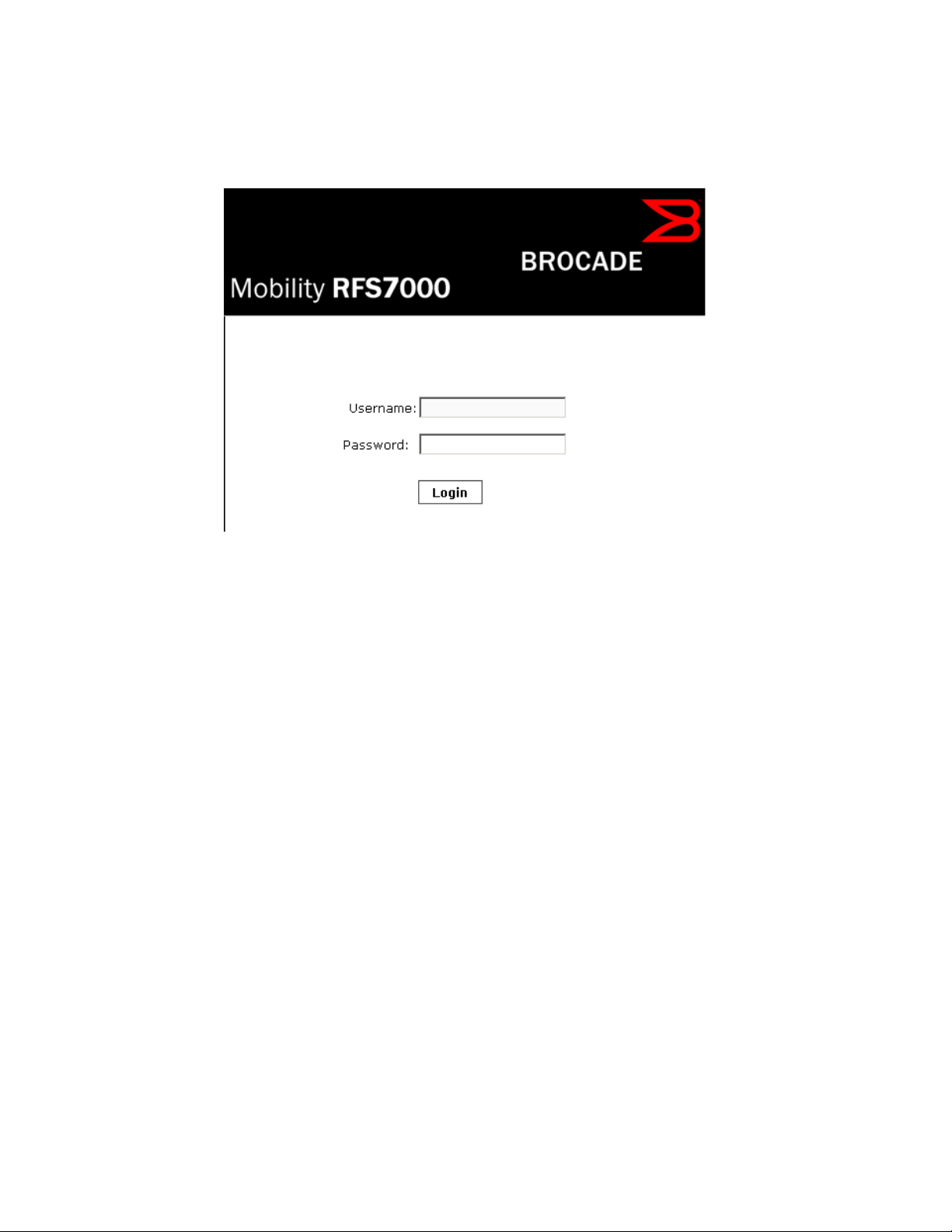
Once the computer has an IP address, point the Web browser to: https://192.168.0.1/ and the
following login screen will display.
FIGURE 1 Web UI Login Screen
Enter the default username admin in the Username field.
Enter the default password admin123 in the Password field.
Click the Login button to load the management interface.
If this is the first time the UI has been accessed, a dialogue displays to begin an initial
setup wizard. For more information on using the initial setup wizard see Using the Initial
Setup Wizard.
Glossary of Icons Used
The UI uses a number of icons used to interact with the system, gather information, and obtain
status for the entities managed by the system. This chapter is a compendium of the icons used.
This chapter is organized as follows:
• Global Icons
• Dialog Box Icons
• Table I c o n s
• Status Icons
• Configurable Objects
• Configuration Objects
• Configuration Operation Icons
• Access Type Icons
• Administrative Role Icons
• Device Icons
4 Brocade Mobility RFS Controller System Reference Guide
53-1003099-01
Page 17
Global Icons
Glossary of Icons Used
This section lists global icons available throughout the interface.
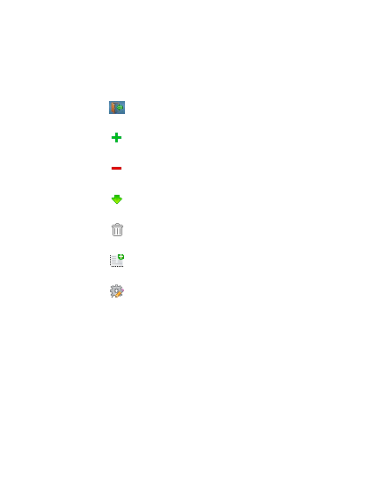
Logout– Select this icon to log out of the system. This icon is always available and is located
at the top right corner of the UI.
Add – Select this icon to add a row in a table. When selected, a new row is created in the
table or a dialog box displays where you can enter values for a particular list.
Delete – Select this icon to remove a row from a table. When selected, the selected row is
deleted.
More Information – Select this icon to display a pop up with supplementary information that
may be available for an item.
2
Dialog Box Icons
Glossary of Icons Used
Tra sh – Select this icon to remove a row from a table. When selected, the row is immediately
deleted.
Create new policy – Select this icon to create a new policy. Policies define different
configuration parameters that can be applied to individual device configurations, profiles
and RF Domains.
Edit policy – Select this icon to edit an existing configuration item or policy. To edit a policy,
select a policy and this icon.
Brocade Mobility RFS Controller System Reference Guide 5
53-1003099-01
Page 18

2
These icons indicate the current state of various controls in a dialog. These icons enables you to
gather the status of all the controls in a dialog. The absence of any of these icons next to a control
indicates the value in that control has not been modified from its last saved configuration.
Entry Updated – Indicates a value has been modified from its last saved configuration.
Entry Update – States that an override has been applied to a device profile
configuration.
Mandatory Field – Indicates this control value is a mandatory configuration item. You
are not allowed to proceed further without providing all mandatory values in this dialog.
Error in Entry – Indicates there is an error in a supplied value. A small red popup
provides a likely cause of the error.
Table Icons
Glossary of Icons Used
The following two override icons are status indicators for transactions:
Table Row Overridden – Indicates a change (profile configuration override) has been
made to a table row and the change will not be implemented until saved. This icon
represents a change from this device’s profile assigned configuration.
Table Row Added – Indicates a new row has been added to a table and the change is
not implemented until saved. This icon represents a change from this device’s profile
assigned configuration.
Status Icons
Glossary of Icons Used
6 Brocade Mobility RFS Controller System Reference Guide
53-1003099-01
Page 19
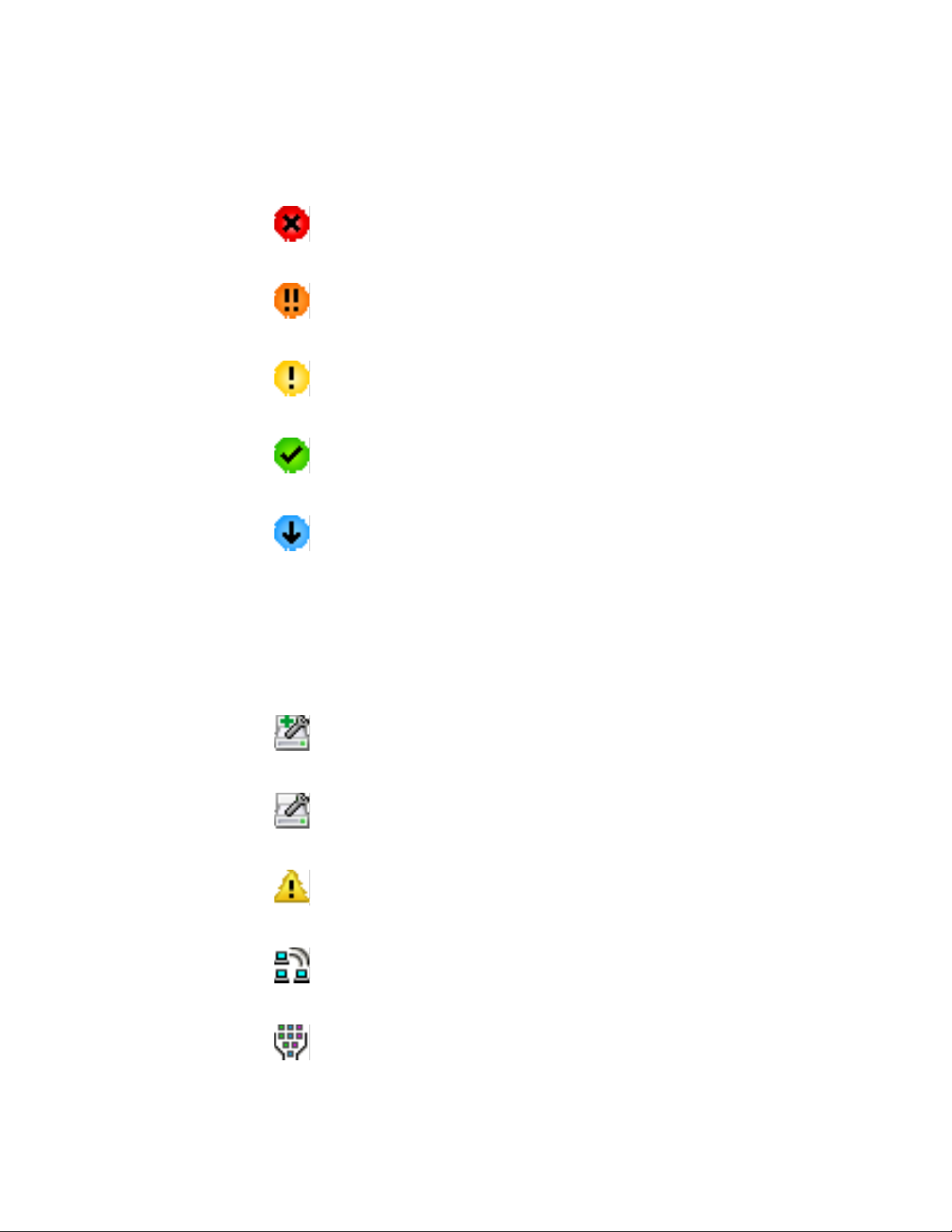
2
These icons indicate device status, operations, or any other action that requires a status returned
to the user.
Fatal Error – States there is an error causing a managed device to stop functioning.
Error – Indicates an error exits requiring intervention. An action has failed, but the error
is not system wide.
Warning – States a particular action has completed, but errors were detected that did
not prevent the process from completing. Intervention might still be required to resolve
subsequent warnings.
Success – Indicates everything is well within the network or a process has completed
successfully without error.
Information – This icon always precedes information displayed to the user. This may
either be a message displaying progress for a particular process, or just be a message
from the system.
Configurable Objects
Glossary of Icons Used
These icons represent configurable items within the UI.
Device Configuration – Represents a configuration file supporting a device category
(Access Point, wireless controller etc.).
Auto Provisioning Policy – Represents a provisioning policy. Provisioning policies are a
set of configuration parameters that define how Access Points and wireless clients are
adopted and their management configuration supplied.
Critical Resource Policy – States a critical resource policy has been applied. Critical
resources are resources whose availability is essential to the network. If any of these
resources is unavailable, an administrator is notified.
Wireless LANs – States an action impacting a managed WLAN has occurred.
WLAN QoS Policy – States a quality of service policy (QoS) configuration has been
impacted.
Brocade Mobility RFS Controller System Reference Guide 7
53-1003099-01
Page 20
2
Radio QoS Policy – Indicates a radio’s QoS configuration has been impacted.
AAA Policy – Indicates an Authentication, Authorization and Accounting (AAA) policy
has been impacted. AAA policies define RADIUS authentication and accounting
parameters.
Association ACL – Indicates an Access Control List (ACL) configuration has been
impacted. An ACL is a set of configuration parameters either allowing or denying
access to network resources.
Smart RF Policy – States a Smart RF policy has been impacted. Smart RF enables
neighboring Access Point radios to take over for an Access Point radio if it becomes
unavailable. This is accomplished by increasing the power of radios on nearby Access
Points to compensate for the coverage hole created by the non-functioning Access
Point.
Profile – States a device profile configuration has been impacted. A profile is a
collection of configuration parameters used to configure a device or a feature.
Bridging Policy – Indicates a bridging policy configuration has been impacted. A
bridging policy defines which VLANs are bridged, and how local VLANs are bridged
between the wired and wireless sides of the network.
RF Domain – States an RF Domain configuration has been impacted.
Firewall Policy – Indicates a firewall policy has been impacted. Firewalls provide a
barrier that prevents unauthorized access to resources while allowing authorized
access to external and internal resources.
IP Firewall Rules – Indicates an IP firewall rule has been applied. An IP based firewall
rule implements restrictions based on the IP address in a received packet.
MAC Firewall Rules – States a MAC based firewall rule has been applied. A MAC based
firewall rule implements network allowance restrictions based on the MAC address in a
received data packet.
Wireless Client Role – Indicates a wireless client role has been applied to a managed
client. The role could be either sensor or client.
WIPS Policy – States the conditions of a WIPS policy have been invoked. WIPS prevents
unauthorized access to the network by checking for (and removing) rogue Access
Points and wireless clients.
8 Brocade Mobility RFS Controller System Reference Guide
53-1003099-01
Page 21
Advanced WIPS Policy – States the conditions of an advanced WIPS policy have been
invoked.
Device Categorization – Indicates a device categorization policy has been applied. This
is used by the intrusion prevention system to categorize Access Points or wireless
clients as either sanctioned or unsanctioned devices. This enables devices to bypass
the intrusion prevention system.
Captive Portals – States a captive portal is being applied. Captive portal is used to
provide temporary controller, service platform or Access Point access to requesting
wireless clients.
DNS Whitelist – A DNS whitelist is used in conjunction with captive portal to provide
access to requesting wireless clients.
DHCP Server Policy – Indicates a DHCP ser ver policy is being applied. DHCP provides IP
addresses to wireless clients. A DHCP server policy configures how DHCP provides IP
addresses.
2
RADIUS Group – Indicates the configuration of RADIUS group has been defined and
applied. A RADIUS group is a collection of RADIUS users with the same set of
permissions.
RADIUS User Pools – States a RADIUS user pool has been applied. RADIUS user pools
are a set of IP addresses that can be assigned to an authenticated RADIUS user.
RADIUS Server Policy – Indicates a RADIUS server policy has been applied. A RADIUS
server policy is a set of configuration attributes used when a RADIUS server is
configured for AAA.
Smart Caching Policy – Smart Caching enables NX4500 and NX6500 series service
platforms to temporarily store frequently accessed Web content on network
infrastructure devices.
Management Policy – Indicates a management policy has been applied. Management
policies configure access control, authentication, traps and administrator permissions.
Configuration Objects
Glossary of Icons Used
Brocade Mobility RFS Controller System Reference Guide 9
53-1003099-01
Page 22
2
These configuration icons are used to define the following:
Configuration – Indicates an item capable of being configured by an interface.
View Events / Event History – Defines a list of events. Click this icon to view events or
view the event history.
Core Snapshots – Indicates a core snapshot has been generated. A core snapshot is a
file that records status events when a process fails on a wireless controller or Access
Point.
Panic Snapshots – Indicates a panic snapshot has been generated. A panic snapshot
is a file that records status when a wireless controller or Access Point fails without
recovery.
UI Debugging – Select this icon/link to view current NETCONF messages.
View UI Logs – Select this icon/link to view the different logs generated by the UI, FLEX
and the error logs.
Configuration Operation Icons
Glossary of Icons Used
The following operations icons are used to define configuration operations:
Revert – When selected, any unsaved changes are reverted to their last saved
configuration settings.
Commit – When selected, all changes made to the configuration are written to the
system. Once committed, changes cannot be reverted.
Commit and Save – When selected, changes are saved to the configuration.
Access Type Icons
Glossary of Icons Used
10 Brocade Mobility RFS Controller System Reference Guide
53-1003099-01
Page 23

The following icons display a user access type:
Web UI – Defines a Web UI access permission. A user with this permission is permitted
to access an associated device’s Web UI.
Tel net – Defines a TELNET access permission. A user with this permission is permitted
to access an associated device using TELNET.
SSH – Indicates a SSH access permission. A user with this permission is permitted to
access an associated device using SSH.
Console – Indicates a console access permission. A user with this permission is
permitted to access an associated device using the device’s serial console.
Administrative Role Icons
2
Glossary of Icons Used
The following icons identify the different administrative roles allowed on the system:
Superuser – Indicates superuser privileges. A superuser has complete access to all
configuration aspects of the connected device.
System – States system user privileges. A system user is allowed to configure general
settings, such as boot parameters, licenses, auto install, image upgrades etc.
Network – Indicates network user privileges. A network user is allowed to configure
wired and wireless parameters, such as IP configuration, VLANs,
L2/L3 security, WLANs and radios.
Security – Indicates security user privileges. A security level user is allowed to
configure all security related parameters.
Brocade Mobility RFS Controller System Reference Guide 11
53-1003099-01
Page 24
2
Monitor – Defines a monitor role. This role provides no configuration privileges. A user
with this role can view the system configuration but cannot modify it.
Help Desk – Indicates help desk privileges. A help desk user is allowed to use
troubleshooting tools like sniffers, execute service commands, view or retrieve logs and
reboot the controller or service platform.
Web User – Indicates a web user privilege. A Web user is allowed accessing the
device’s Web UI.
Device Icons
Glossary of Icons Used
The following icons represent the different device types managed by the system:
System – This icon represents the entire Mobility supported system, and all of its
member controller, service platform or Access Points that may be interacting at any
one time.
Cluster – This icon represents a cluster. A cluster is a set of wireless controllers or
service platforms working collectively to provide redundancy and load sharing
amongst its members.
Service Platform – This icon indicates an NX45xx, NX65xx or NX9000 series service
platform that’s part of the managed network
Wireless Controller – This icon indicates a RFS6000 or a RFS7000 wireless controller
that’s part of the managed network.
Wireless Controller – This icon indicates a RFS4000 wireless controller that’s part of
the managed network.
Access Point – This icon lists any Access Point that’s part of the managed network.
Wireless Client – This icon defines any wireless client connection within the network.
12 Brocade Mobility RFS Controller System Reference Guide
53-1003099-01
Page 25
Chapter
Quick Start
RFS4011 model controllers utilize an initial setup wizard to streamline getting on the network for
the first time. This wizard configures location, network and WLAN settings and assists in the
discovery of Access Points and their connected clients. For instructions on how to use the initial
setup wizard, see Using the Initial Setup Wizard on page 3-13.
Using the Initial Setup Wizard
Once deployed and powered on, complete the following to get the controller or service platform up
and running and access more advanced user interface functions:
1. Connect one end of an Ethernet cable to a port on the front of the controller or service
platform, and connect the other end to a computer with a working Web browser.
2. Set the computer to use an IP address between 192.168.0.10 and 192.168.0.250 on the
connected port. Set a
subnet/network mask of 255.255.255.0.
3. Once the computer has an IP address, point the Web browser to: https://192.168.0.1/. The
following login screen displays.
3
FIGURE 1 Web UI Login Screen
Enter the default username admin in the Username field.
4. Enter the default password admin123 in the Password field.
Select the preferred language to display for the graphical user interface (GUI).
Brocade Mobility RFS Controller System Reference Guide 13
53-1003099-01
Page 26
3
NOTE
NOTE
5. Select the Login button to load the management interface.
When logging in for the first time, you are prompted to change the password to enhance device
security in subsequent logins.
If you get disconnected when running the wizard, you can connect again and resume the wizard
setup.\
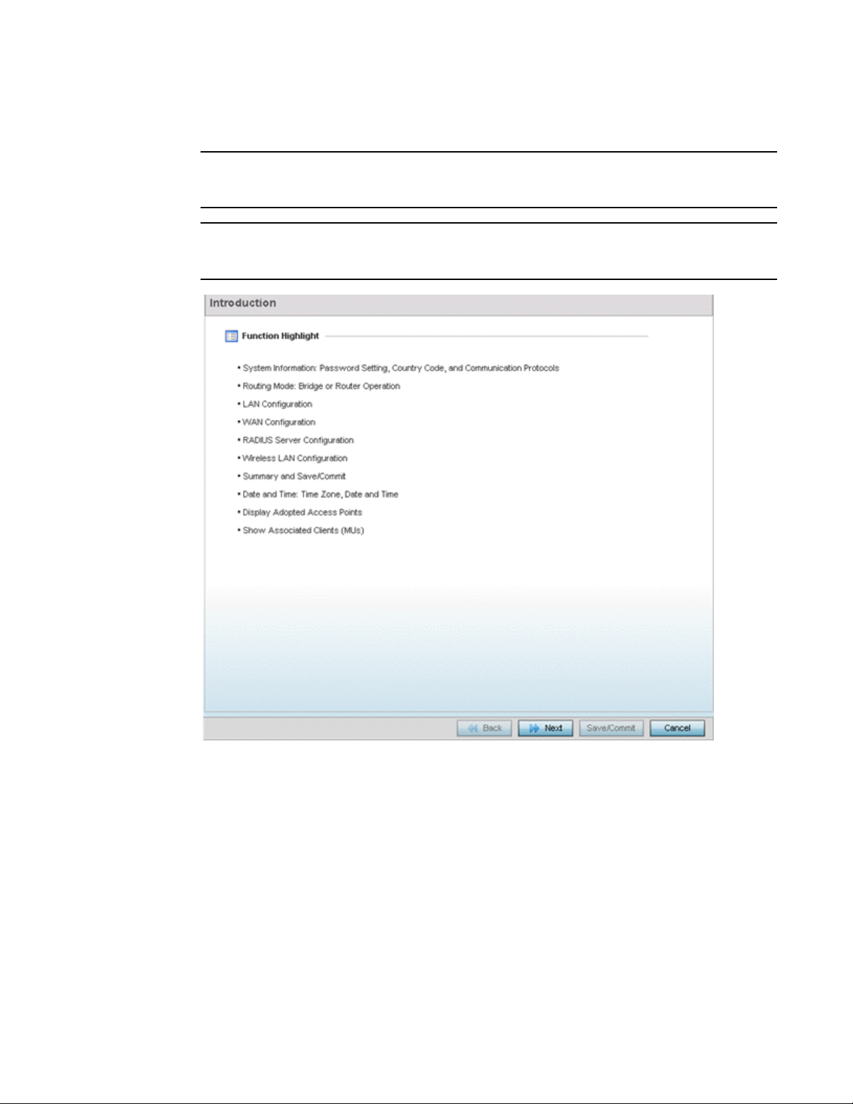
FIGURE 2 Initial Setup Wizard - Introduction
The Introduction screen displays first (on the right-hand side of the screen), and lists the
various actions that can be performed using the setup wizard.
The wizard displays a Navigation Panel on the left-hand side of each screen to assist the
administrator in assessing which tasks still require completion before the RFS4011,
NX4500 or NX6500 can be deployed.
14 Brocade Mobility RFS Controller System Reference Guide
53-1003099-01
Page 27
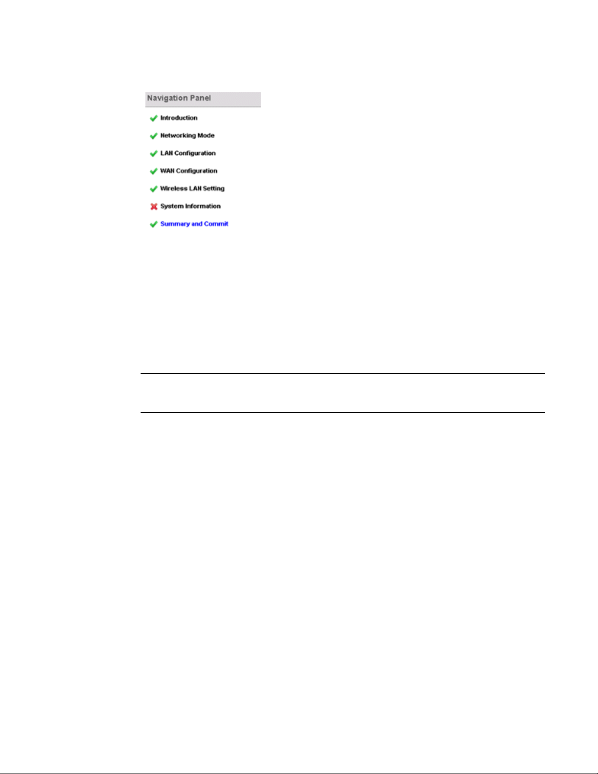
FIGURE 3 Initial Setup Wizard - Navigation Panel
NOTE
A green checkmark to the left of an item in the Navigation Panel defines the task as having
its minimum required configuration set correctly. A red X defines a task as still requiring at
least one parameter be defined correctly.
Select Save/Commit within each page to save the updates made to that page's
configuration. Select Next to proceed to the next page listed in the Navigation Panel.
Select Back to revert to the previous screen in the Navigation Panel without saving your
updates. Selecting Cancel closes the wizard without committing any updates.
3
While you can scroll to any page in the Navigation Panel at any time, you cannot complete the wizard
until each task in the Navigation Panel has a green checkmark displayed to the left of the task.
6. Select Next. The wizard displays the Networking Mode screen to define routing or bridging
functionality
.
Brocade Mobility RFS Controller System Reference Guide 15
53-1003099-01
Page 28
3
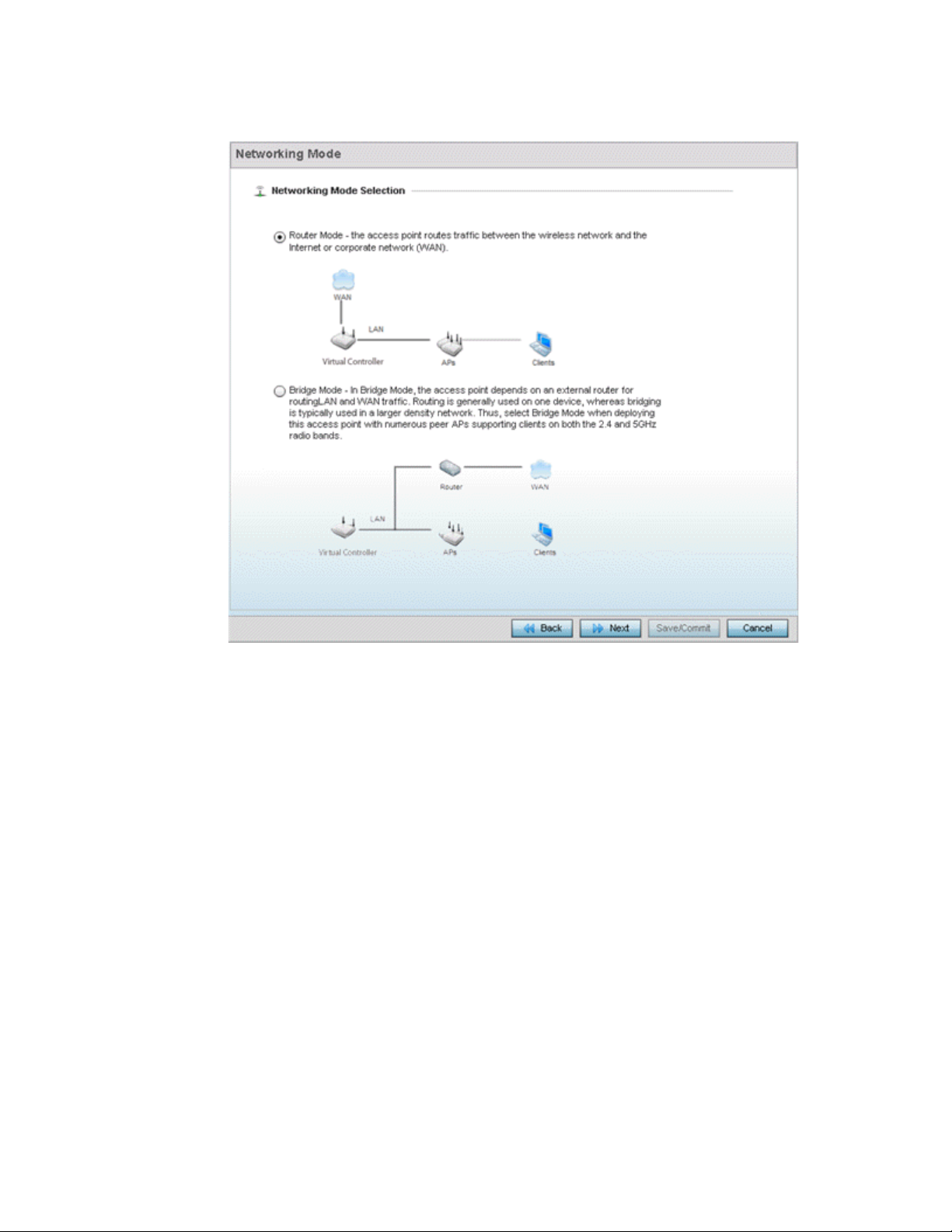
FIGURE 4 Initial Setup Wizard - Networking Mode
7. Select one of the following network mode options:
• Router Mode - In Router Mode, connected Access Points route traffic between the local
network (LAN) and the Internet or external network (WAN). Router mode is recommended
in a deployment supported by just a single Access Point. When Router Mode is selected,
an additional WAN screen is available in wizard screen flow to configure interface settings
for an Access Point’s WAN port.
• Bridge Mode - In Bridge Mode, connected Access Points depend on an external router for
routing LAN and WAN traffic. Routing is generally used on one device, whereas bridging is
typically used in a larger network. Thus, select Bridge Mode when deploying numerous
peer Access Points supporting clients on both the 2.4 and 5GHz radio bands.
Select Next. The wizard displays the LAN Configuration screen to set the LAN interface
configuration.
16 Brocade Mobility RFS Controller System Reference Guide
53-1003099-01
Page 29
3
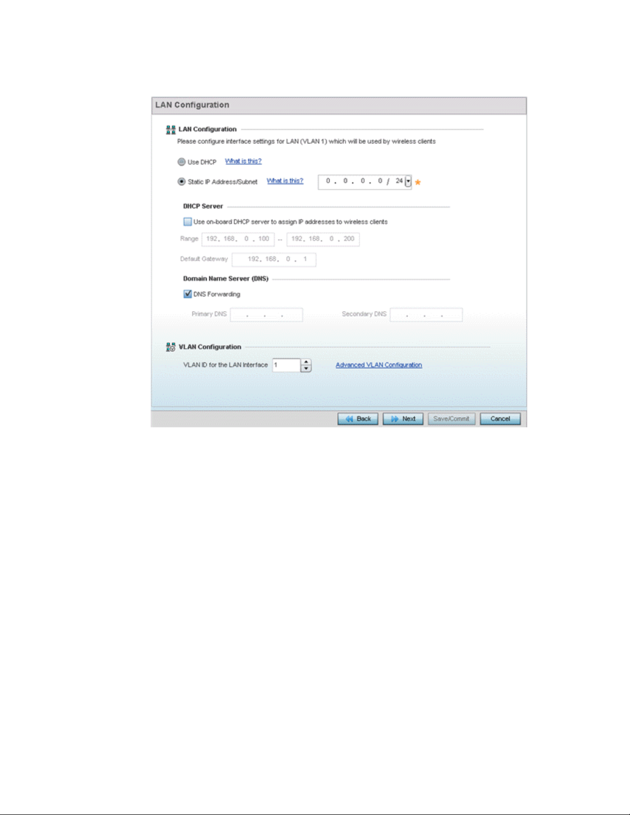
FIGURE 5 Initial Setup Wizard - LAN Configuration
Set the following DHCP, Static IP Address/Subnet and VLAN information for the LAN interface:
• Use DHCP - Select Use DHCP to enable an automatic network address configuration using
local DHCP server resources.
• Static IP Address/Subnet - Enter an IP Address and a subnet for the LAN interface. If Use
DHCP is selected, this field is not available. When selecting this option, define the
following DHCP Server and Domain Name Server (DNS) resources, as those fields are
enabled on the bottom portion of the screen.
• Use on-board DHCP server to assign IP addresses to wireless clients -Select this
option to enable the DHCP server to provide IP and DNS support to requesting clients
on the LAN interface.
• Range - Enter a starting and ending IP Address range for client assignments on the
LAN interface. Avoid assigning IP addresses from x.x.x.1 - x.x.x.10 and x.x.x.255, as
they are often reserved for standard network services. This is a required parameter.
• Default Gateway - Define a default an address for use with the default gateway. This is
a required parameter.
• DNS Forwarding - Select this option to allow a DNS server to translate domain names into
IP addresses. If this option is not selected, a primary and secondary DNS resource must
be specified. DNS forwarding is useful when a request for a domain name is made but the
DNS server, responsible for converting the name into its corresponding IP address, cannot
locate the matching IP address.
Brocade Mobility RFS Controller System Reference Guide 17
53-1003099-01
Page 30
3
• Primary DNS - Enter an IP Address for the main Domain Name Server providing DNS
services for the LAN interface.
• Secondary DNS - Enter an IP Address for the backup Domain Name Server providing
DNS services for the LAN
interface.
Use the spinner control to select a VLAN ID for the LAN Interface. Optionally select Advanced VLAN
Configuration to populate the screen with additional VLAN parameters for the LAN interface.
Select Next. If Router was selected as the Access Point mode the wizard displays the WAN
Configuration screen. If Bridge was selected, the wizard proceeds to the Wireless LAN Setting
screen.
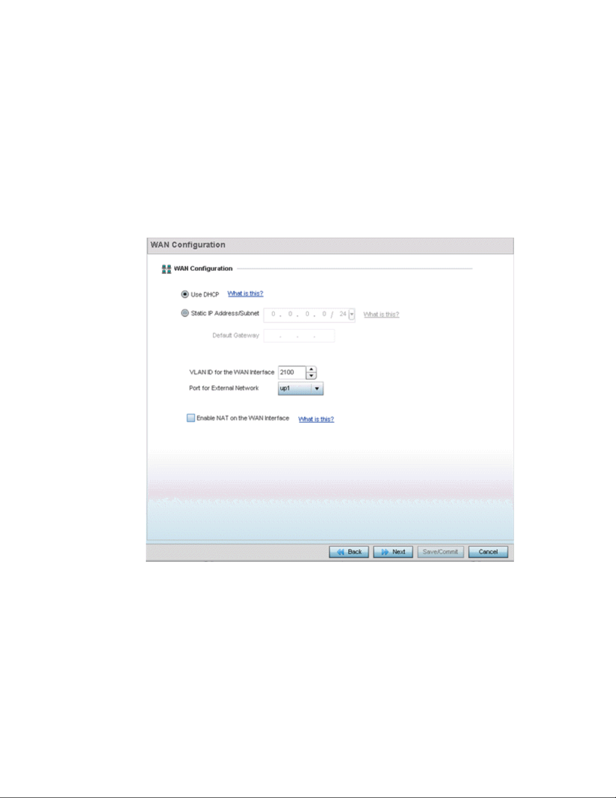
FIGURE 6 Initial Setup Wizard - WAN Configuration
Set the following DHCP and Static IP Address/Subnet information to define how traffic is routed
between the local network (LAN) and the Internet or external network (WAN).
• Use DHCP - Select Use DHCP to enable an automatic network address configuration using
local DHCP server resources.
• Static IP Address/Subnet - Enter an IP Address/Subnet and gateway for the WAN interface.
These are required fields
• Default Gateway -Enter an IP Address for the default gateway on the WAN interface. If
Use DHCP is enabled, this field is not configurable.
18 Brocade Mobility RFS Controller System Reference Guide
53-1003099-01
Page 31

• VLAN ID for the WAN Interface - Set the VLAN ID (virtual interface) to associate with
the physical WAN Interface. The default setting is VLAN 2100.
• Port for External Network - Select the physical port connected to the WAN interface.
The list of available ports varies based on the RFS4011 controllers or NX4500 and
NX6500 service platform model.
• Enable NAT on the WAN Interface - Select the option to allow traffic to pass between
WAN and LAN interfaces.
Select Next. The wizard displays the Wireless LAN Setting screen to define up to four WLAN
configurations for the controller or service platform.
3
FIGURE 7 Initial Setup Wizard - Wireless LAN Settings
Set the following parameters for up to four WLAN configurations:
• SSID - Enter or modify the Services Set Identification (SSID) associated with the WLAN. The
WLAN name is
auto-generated using the SSID until changed by the administrator. The maximum number
of characters is 32. Do not use any of these characters (< > | " & \ ? ,).
• WLAN Type - Select a basic authentication and encryption scheme for the WLAN. Available
options include:
• No Authentication and No Encryption (provides no security at all)
• Captive Portal Authentication and No Encryption
• PSK authentication, WPA2 encryption
Brocade Mobility RFS Controller System Reference Guide 19
53-1003099-01
Page 32
3
• EAP Authentication and WPA2 Encryption
Select Next. The wizard displays the System Information screen to set device deployment,
administrative contact and system time information. The system time can either be set manually or
be supplied by a dedicated Network Time Protocol (NTP) resource.
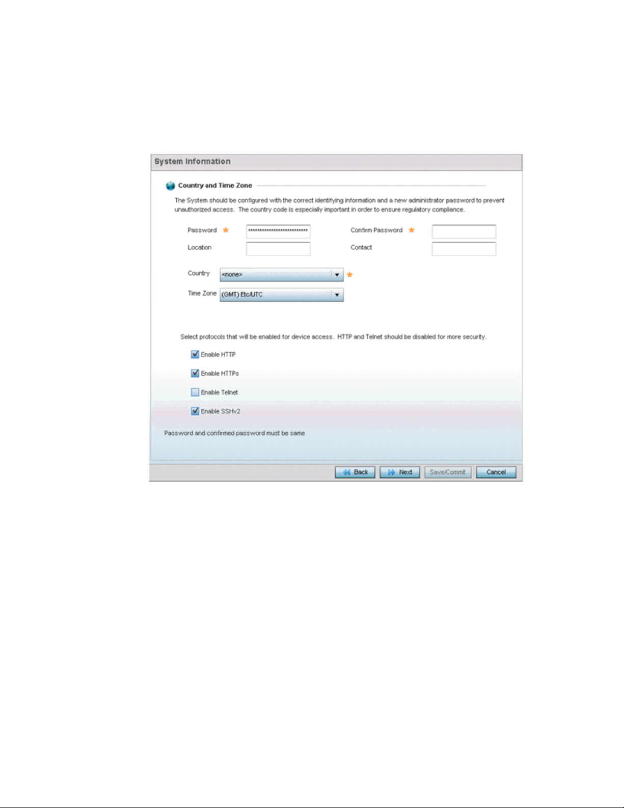
FIGURE 8 Initial Setup Wizard - System Information
Refer to the Country and Time Zone field to set the following deployment information:
• Password - Enter and confirm a system password used to login into the controller or
service platform on subsequent login attempts.Changing the default system password is
strongly recommended to secure the proprietary configuration data maintained on the
controller or service platform.
• Location - Define the location of the controller or service platform deployment.
• Contact - Specify the contact information for the administrator. The credentials provided
should accurately reflect the individual responding to service queries.
• Country - Select the country where the controller or service platform is deployed. The
controller or service platform prompts for the correct country code on the first login. A
warning message also displays stating an incorrect country setting may result in illegal
radio operation. Selecting the correct country is central to legal operation. Each country
has its own regulatory restrictions concerning electromagnetic emissions and the
maximum RF signal strength that can be transmitted.
20 Brocade Mobility RFS Controller System Reference Guide
53-1003099-01
Page 33
3
• Time Zone - Set the time zone where the controller or service platform is deployed. This is
a required parameter. The setting should be complimentary with the selected deployment
country.
Refer to the Select protocols that will be enabled for device access area and enable those
controller or service platform interfaces for accessing the controller or service platform. HTTP and
Telnet are considered relatively insecure and only should be enabled is necessary.
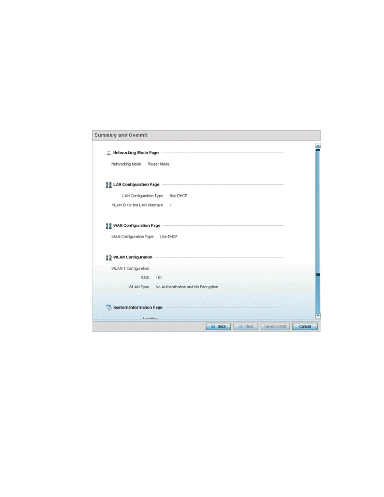
Select Next. The wizard displays the Summary and Commit screen to summarize the screens
(pages) and settings updated using the wizard.
FIGURE 9 Initial Setup Wizard - Summary and Commit
No user intervention or additional settings are required within this screen. Its an additional
means of validating the Access Point’s updated configuration before its deployed.
However, if a screen displays settings not intended as part of the initial configuration, the
any screen can be selected again from within the Navigation Panel and its settings
modified accordingly.
If the configuration displays as intended, select Save/Commit to implement these settings to the
controller or service platform configuration. If additional changes are warranted based on the
summary, either select the target page from the Navigational Panel, or use the Back and Next
buttons to scroll to the target screen.
Brocade Mobility RFS Controller System Reference Guide 21
53-1003099-01
Page 34

3
22 Brocade Mobility RFS Controller System Reference Guide
53-1003099-01
Page 35

Chapter
Dashboard
Summary
4
The dashboard enables administrators to review and troubleshoot network device operation.
Additionally, the dashboard allows an administrative review of the network’s topology, an
assessment of network’s component health and a diagnostic review of device performance.
By default, the Dashboard displays the System screen, which is the top level in the device
hierarchy. To view information for Access Points, RF Domains or Controllers select the associated
item in the tree.
The Dashboard displays information organized by device association and inter-connectivity
between the connected Access Points and wireless clients.
1. To review dashboard information, select Dashboard.
2. Select Summary if its not already selected by default.
The Dashboard displays the Health tab by default.
Brocade Mobility RFS Controller System Reference Guide 23
53-1003099-01
Page 36
4
FIGURE 1 System Dashboard screen - Health tab
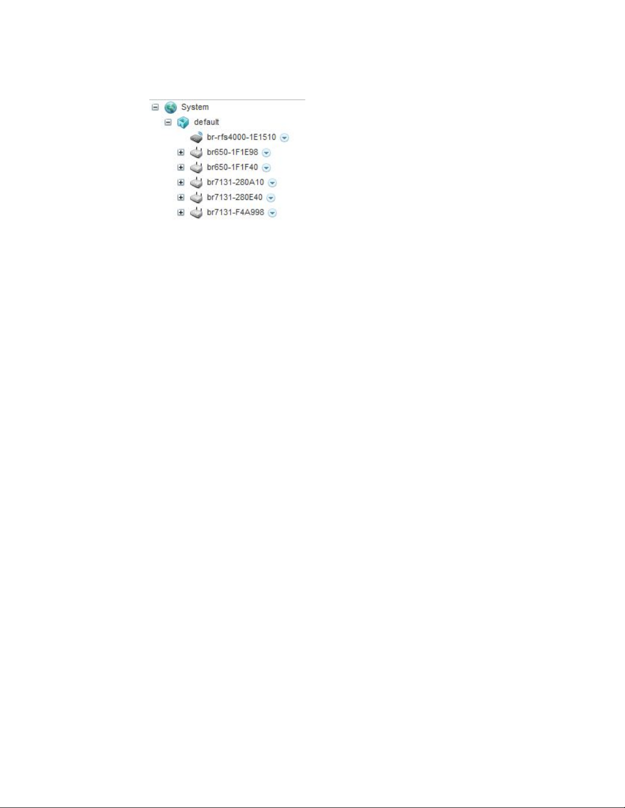
Device Listing
Summary
The device menu displays information as a hierarchical tree, comprised of system,
controller/service platform and Access Point connection relationships.
24 Brocade Mobility RFS Controller System Reference Guide
53-1003099-01
Page 37
4
FIGURE 2 Dashboard Menu Tree
The Search option, at the bottom of the screen, enables you to filter (search amongst) RF Domains.
The By drop-down menu refines the search. You can further refine a search using the following:
• Auto – The search is automatically set to device type.
• Name – The search is performed for the device name specified in the Search text box.
• WLAN – The search is performed for the WLAN specified in the Search text box.
• IP Address – The search is performed for the IP Address specified in the Search text box.
• MAC Address – The search is performed for the MAC Address specified in the Search text box.
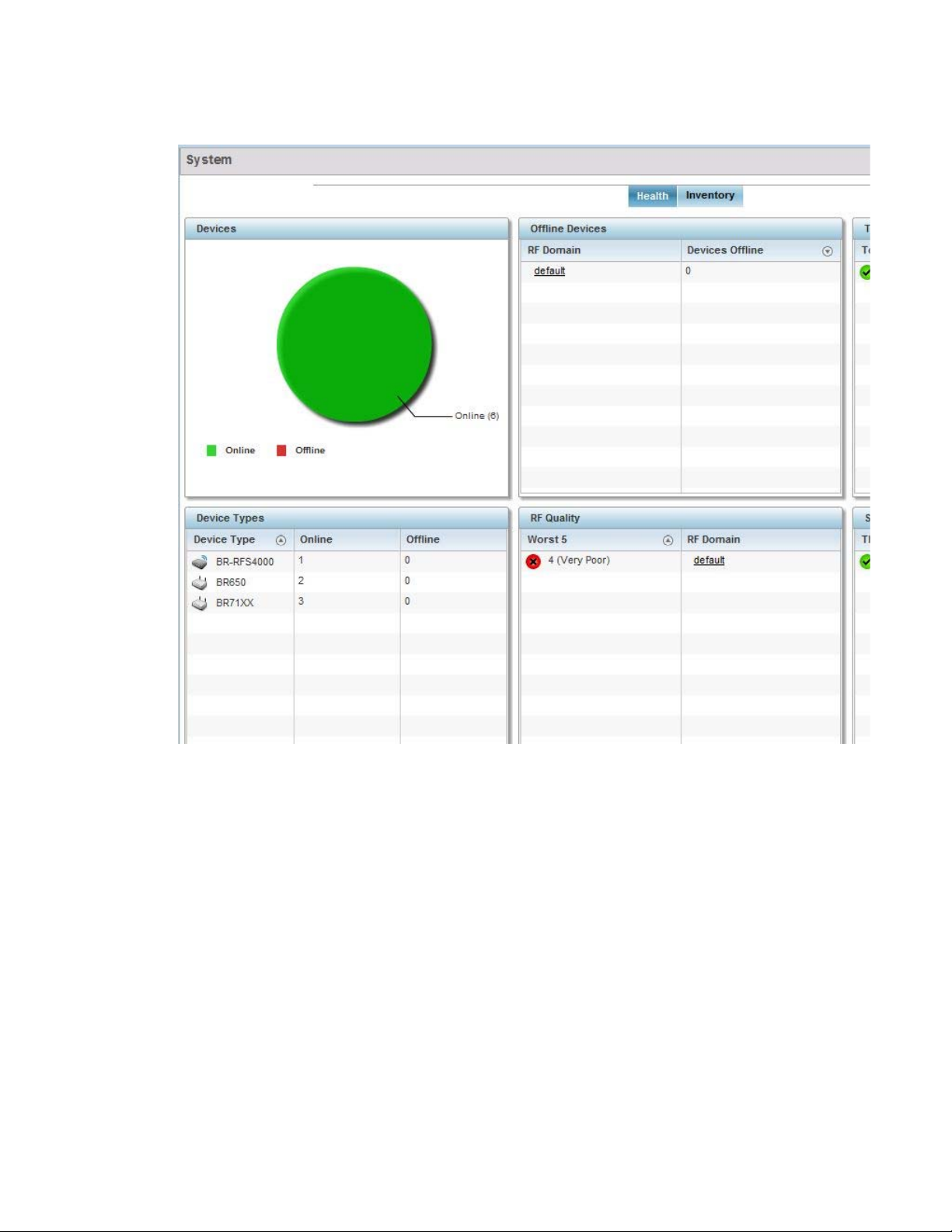
System Screen
The System screen displays system-wide network status. The screen is partitioned into the
following tabs:
• Health – The Health tab displays information about the state of the Mobility device managed
• Inventory – The Inventory tab displays information on the physical devices managed within the
Health
Health
The Health tab displays device performance status for managed devices, and includes their RF
Domain memberships.
To assess system health:
1. Select Dashboard.
2. Select Summary if its not already selected by default.
3. Select System. The Health tab displays by default.
system.
Mobility wireless network.
Brocade Mobility RFS Controller System Reference Guide 25
53-1003099-01
Page 38
4
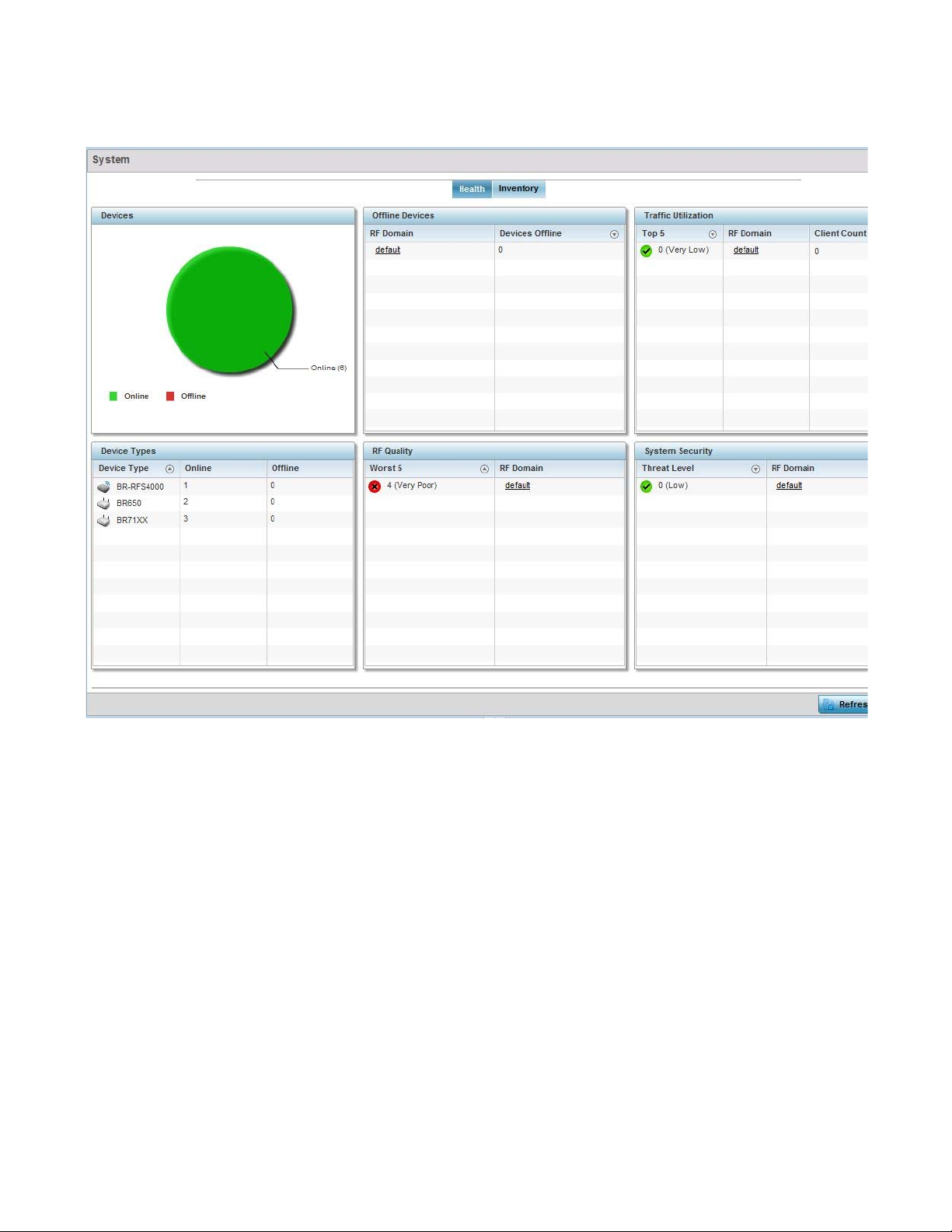
FIGURE 3 System Dashboard screen - Health tab
The Health screen is partitioned into the following fields:
• The Devices field displays a ratio of offline versus online devices within the system. The
information is displayed in pie chart format to illustrate device support ratios.
• The Device Type field displays a numerical representation of the different controller, service
platform and Access Point models in the current system. Their online and offline device
connections are also displayed. Does this device distribution adequately support the number
and types of Access Point radios and their client load requirements.
• The Offline Devices field displays a table of supported RF Domains within the system, with
each RF Domain listing the number offline devices within that RF Domain. Listed RF Domains
display as individual links that can be selected to RF Domain information in greater detail.
• The RF Quality Index displays RF quality per RF Domain. It's a measure of the overall
effectiveness of the RF environment displayed in percentage. It's a function of the connect rate
in both directions, retry rate and error rate.
The RF Quality field displays an average quality index supporting each RF Domain. The table
lists the bottom five (5) RF quality values for RF Domains. Listed RF Domains display as
26 Brocade Mobility RFS Controller System Reference Guide
53-1003099-01
Page 39

4
individual links that can be selected to RF Domain information in greater detail. Use this
diagnostic information to determine what measures can be taken to improve radio
performance in respect to wireless client load and the radio bands supported.
The quality is measured as:
• 0-20 – Very poor quality
• 20-40 – Poor quality
• 40-60 – Average quality
• 60-100 – Good quality
• The System Security field displays RF intrusion prevention stats and their associated threat
level. The greater the number of unauthorized devices, the greater the associated threat level.
The System Security field displays a list of up to five RF Domains in relation to the number of
associated wireless clients. The RF Domains appear as links that can be selected to display RF
Domain information in greater detail.
Inventory
System Screen
The system screen’s Inventory tab displays granular data on specific devices supported within the
network. The screen provides a complete overview of the number and state Mobility managed
devices. Information is displayed in easy to read tables and graphs. This screen also provides links
for more detailed information.
To assess the system inventory:
1. Select Dashboard.
2. Select Summary if its not already selected by default.
3. Select System.
4. Select the Inventory tab.
Brocade Mobility RFS Controller System Reference Guide 27
53-1003099-01
Page 40
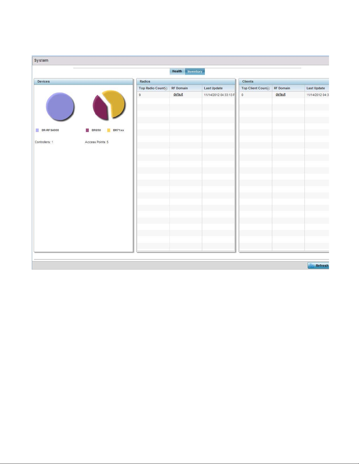
4
FIGURE 4 System screen - Inventory tab
The information within the Inventory tab is partitioned into the following fields:
• The Devices field displays a ratio of peer controllers and service platforms as well as their
managed Access Point radios. The information is displayed in pie chart format. The Device Type
field displays a numerical representation of the different controller models and connected
Access Points in the current system.
• The Radios field displays top performing radios, their RF Domain memberships and a status
time stamp. RF Domain information can be selected to review RF Domain membership
information in greater detail.Information in the Radio area is presented in two tables. The first
lists the total number of Radios managed by this system, the second lists the top five RF
Domains in terms of the number of available radios.Information in the Radio area is presented
in two tables. The first lists the total number of Radios managed by this system, the second
lists the top five RF Domains in terms of the number of available radios.
• The wireless Clients field lists the top five RF Domains with the highest total number of clients
managed by connected devices in this system. Select Refresh as needed update the screen to
its latest values.
28 Brocade Mobility RFS Controller System Reference Guide
53-1003099-01
Page 41

RF Domain Screen
RF Domains allow administrators to assign configuration data to multiple devices deployed in a
common coverage area, such as in a floor, building or site. Each RF Domain contains policies that
can determine a Smart RF or WIPS configuration.RF Domains enable administrators to override
WLAN SSID name and VLAN assignments. This enables the deployment of a global WLAN across
multiple sites and unique SSID name or VLAN assignments to groups of Access Points servicing the
global WLAN. This WLAN override technique eliminates the requirement for defining and managing
a large number of individual WLANs and profiles.
A configuration contains (at a minimum) one default RF Domain and can optionally use additional
user defined RF Domains:
• Default RF Domain - Automatically assigned to each controller or service platform and associated
Access Point by default.
• User Defined RF Domains - Created by administrators and manually assigned to individual
controller or service platforms, but can be automatically assigned to Access Points using adoption
policies.
Each controller and service platform is assigned to only one RF Domain at a time. However, a user
defined RF Domain can be assigned to multiple controllers or service platforms as required. User
defined RF Domains can be manually assigned or automatically assigned to Access Points using an
AP provisioning policy.
4
The RF Domain screen displays system-wide network status. The screen is partitioned into the
following tabs:
• RF Domain Health – The Health tab displays information about the state of the RF Domain and
network performance as tallied from its collective device members.
• RF Domain Inventory – The Inventory tab displays information on the physical devices
comprising the RF Domain.
RF Domain Health
The Health tab displays the status of the RF Domain’s device membership.
To assess the RF Domain health:
1. Select Dashboard.
2. Select Summary if its not already selected by default.
3. Expand the System node to display RF Domains.
4. Select a RF Domain. The Health tab displays by default.
Brocade Mobility RFS Controller System Reference Guide 29
53-1003099-01
Page 42

4
FIGURE 5 RF Domain screen - Health tab
Refer to the following RF Domain health information for member devices:
• The Domain field lists the RF Domain manager reporting utilization statistics. The MAC address
displays as a link that can be selected to display RF Domain information in at more granular
level.
• The Devices field displays the total number of devices and the status of the devices in the
network as a graph. This area displays the total device count managed by this device and their
status (online vs. offline) as a pie graph.
• The Radio Quality table displays a table of RF quality on a per radio basis. It is a measure of the
overall effectiveness of the RF environment displayed in percentage. It is a function of the
transmit retry rate in both directions and the error rate. This area of the screen displays the
average quality index across all the defined RF Domain on the wireless controller. The table
lists worst five of the RF quality values of all the radios defined on the wireless controller. The
quality is measured as:
• 0-20 - Very poor quality
• 20-40 - Poor quality
• 40-60 - Average quality
30 Brocade Mobility RFS Controller System Reference Guide
53-1003099-01
Page 43

4
• 60-100 - Good quality
Select a Radio Id to view all the statistics for the selected radio in detail.
• The Client Quality table displays RF quality for the worst five performing clients.It is a function
of the transmit retry rate in both directions and the error rate. This area of the screen displays
the average quality index across all the defined RF Domain on the wireless controller. The
quality is measured as:
• 0-20 - Very poor quality
• 20-40 - Poor quality
• 40-60 - Average quality
• 60-100 - Good quality
Select a client to view its statistics in greater detail.
• WLAN Utilization displays how efficiently the WLANs are used. Traffic utilization is defined as
the percentage of current throughput relative to the maximum possible throughput for the
WLAN. The total number of WLANs is displayed above the table. The table displays a list of the
top five WLANs in terms of overall traffic utilization. It displays the utilization level names,
WLAN name and SSIDs for each of the top five WLANs.
• Radio Traffic Utilization displays how efficiently the RF medium is used. Traffic utilization is
defined as the percentage of current throughput relative to the maximum possible throughput
for the RF Domain. The Traffic Index area displays an overall quality level for radio traffic and
the Max User Rate displays the maximum data rate of associated radios. The table displays a
list of the top five radios in terms of overall traffic utilization quality. It displays the radio
names, MAC Addresses and radio types for each of the top five radios.
• Client Traffic Utilization displays how efficiently the RF medium is utilized for connected clients.
Traffic utilization is defined as the percentage of current throughput relative to the maximum
possible throughput for the clients in the RF Domain. The table displays a list of the top five
performing clients in respect to overall traffic utilization. It displays the client names, MAC
Addresses and vendor for each of the top five clients.
• The Wireless Security field displays the overall threat index for the system. This index is based
on the number of Rogue/Unsanctioned APs and Wireless Intrusion Protection System (WIPS)
events. The index is in the range 0 to 5 where 0 indicates that there are no detected threats.
An index of 5 indicates that a large number of intrusion detection events or
rogue/unsanctioned APs detected.
• Traffic Statistics include transmit and receive values for Total Bytes, Total Packets, User Data
Rate, Broadcast/Multicast Packets, Management Packets, Tx Dropped Packets and Rx Errors.
RF Domain Inventory
Refer to the following RF Domain inventory data collected by member controllers, service platforms
or Access Points:
To review the RF Domain inventory:
1. Select Dashboard.
2. Select Summary if its not already selected by default.
3. Expand the System node to display RF Domains.
4. Select a RF Domain.
Brocade Mobility RFS Controller System Reference Guide 31
53-1003099-01
Page 44

4
5. Select the Inventory tab.
FIGURE 6 RF Domain screen - Inventory tab
The Inventory tab displays information on the devices managed by RF Domain member devices in
the controller, service platform or Access Point managed network. The Inventory screen enables an
administrator to overview of the number and state of the devices in the selected RF Domain.
Information is displayed in easy to read tables and graphs.
• The Device Types table displays the devices types populating the RF Domain. The Device Type
area displays an exploded pie chart that displays the type of device and their numbers in the
RF Domain.
• The Radios by Band table displays a bar graph of RF Domain member device radios classified
by their radio band or sensor dedication. Review this information to assess whether RF Domain
member radios adequately support client device traffic requirements.
• The Radios by Channel table displays pie charts of the different channels utilized by Rf Domain
member radios. These dedicated channels should be as segregated as possible from one
another to avoid interference. If too many radios are utilizing a single channel, consider
off-loading radios to non utilized channels to improve RF Domain performance.
• The Top 5 Ra d i o s by Clients table displays a list of radios that have the highest number of
clients. This list displays the radio IDs as links that can be selected to display individual radio
information in greater detail.
32 Brocade Mobility RFS Controller System Reference Guide
53-1003099-01
Page 45

Controller
4
• The WLANs table displays a list of WLANs utilized by RF Domain member devices. The table is
ordered by WLAN member device radio count and their number of connected clients. Use this
information to assess whether the WLAN is overly populated by radios and clients contributing
to congestion.
• The Client of Channels table displays a bar-graph of wireless clients classified by their
frequency. Information for each channel is further classified by their 802.11x band. In the
5GHz channel, information is displayed classified under 802.11a and 802.11an bands. In the
2.4 GHz channel, information is displayed classified under 802.11b, 802.11bg, and
802.11bgn band.
The Wireless Controller screen displays system collected network status for controllers and service
platforms. The screen is partitioned into two tabs:
• Controller Health – The Health tab displays information about the state of the controller or
service platform managed wireless network.
• Controller Inventory – The Inventory tab displays information on the physical devices managed
by the controller or service platform.
Controller Health
To assess the controller or service platform’s network health:
1. Select Dashboard.
2. Select Summary if its not already selected by default.
3. Expand the System node to display RF Domains.
4. Select and expand a RF Domain to expose its member controllers or service platforms.
5. Select a controller or service platform. The Health tab display by default.
Brocade Mobility RFS Controller System Reference Guide 33
53-1003099-01
Page 46

4
FIGURE 7 Wireless Controller screen - Health tab
Refer to the Device Details table for information about the selected controller or service platform
The following information is displayed:
• Hostname - Lists the administrator assigned name of the controller or service platform.
• Device MAC - Lists the factory encoded MAC address of the controller or service platform.
• Typ e - Indicates the type of controller or service platform. An icon representing the RFS
controller is displayed along with the model number.
• RF Domain Name - Lists the RF Domain to which the controller or service platform belongs. The
RF Domain displays as a link that’s selectable to display Rf Domain data in greater detail.
• Model Number - Lists the model number and hardware SKU information of the selected
controller or service platform to refine its intended deployment region.
• Version - Lists the firmware version currently running on the controller or service platform.
Compare this version against the version currently on the support site to ensure the controller
or service platform has the latest feature set available.
• Uptime - Displays the duration the controller or service platform has been running since it was
last restarted.
• CPU - Displays the CPU installed on this controller or service platform.
34 Brocade Mobility RFS Controller System Reference Guide
53-1003099-01
Page 47

4
• RAM - Displays the amount of RAM available for use in this system.
• System Clock - Displays the current time set on the controller or service platform.
The Adopted Devices Health (w/ cluster members) displays a graph of Access Points in the system
with the available Access Points in green and unavailable Access Points in red.
The Radio RF Quality Index provides a table of RF quality on a per radio basis. It is a measure of the
overall effectiveness of the RF environment displayed in percentage. It is a function of the connect
rate in both directions, the retry rate and the error rate. The screen displays the average quality
index within the Access Point single radio. The table lists bottom five (5) of the RF quality values by
Access Point radio. The quality is measured as:
• 0-20 - Very poor quality
• 20-40 - Poor quality
• 40-60 - Average quality
• 60-100 - Good quality
Select a radio Id to view statistics in greater detail.
The Radio Utilization table displays how efficiently the RF medium is used. Radio utilization is
defined as the percentage of current throughput relative to the maximum possible throughput for
the radio. The Radio Utilization table displays the Access Point radios in terms of the number of
associated wireless clients and the percentage of utilization. It also displays a table of packets
types transmitted and received.
The Client RF Quality table displays a table of RF quality on a per client basis. It is a measure of the
overall effectiveness of the RF environment displayed in percentage. It is a function of the connect
rate in both directions, the retry rate and the error rate. This area of the screen displays the average
quality index for a client. The table lists bottom five (5) of the RF quality values by a client. Quality is
measured as:
• 0-20 - Very poor quality
• 20-40 - Poor quality
• 40-60 - Average quality
• 60-100 - Good quality
Select a client MAC to view all the statistics for the selected client in greater detail.
Controller Inventory
The Inventory tab displays information for the devices managed by the system. This screen enables
a system administrator to have a complete overview of the number and state of managed devices.
Information is displayed in easy to read tables and graphs. The Inventory screen also provides links
for the system administrator to get more detailed information.
To assess the controller or service platform inventory:
1. Select Dashboard.
2. Select Summary if its not already selected by default.
3. Expand the System node to display RF Domains.
4. Select and expand a RF Domain to expose its member controllers or service platforms.
5. Select a controller or service platform.
Brocade Mobility RFS Controller System Reference Guide 35
53-1003099-01
Page 48
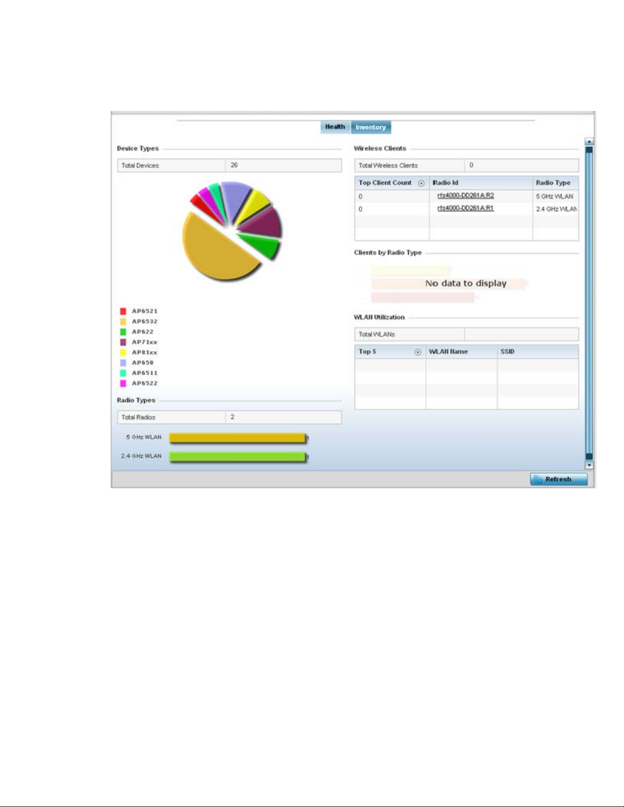
4
6. Select the Inventory tab.
FIGURE 8 Wireless Controller screen - Inventory tab
The Inventory tab displays information on the devices managed by the controller or service
platform. The Inventory screen enables an administrator to overview of the number and state of
controller or service platform managed devices and their utilization. Refer to the following Inventory
data:
• The Device Types field displays a ratio of devices managed by this controller or service platform
in pie chart format. The Device Type area displays an exploded pie chart that displays the type
of device and their numbers in the current system.
• The Radios Type field displays the total number of radios managed by this controller or service
platform. The graph lists the number of radios in both the 2.4 GHz and 5 GHz radio bands.
• The Wireless Clients table lists clients managed by this controller or service platform by
connected client count. Information is presented in two (2) tables and a graph. The first table
lists the total number of clients managed by the listed controller or service platform. The
second lists the top five (5) radios in terms of the number of connected clients. The graph just
below the table lists the number of clients by radio type.
36 Brocade Mobility RFS Controller System Reference Guide
53-1003099-01
Page 49

• The WLAN Utilization table displays utilization statistics for controller or service platform WLAN
configurations. Information displays in two tables. The first table lists the total number of
WLANs managed by this system. The second table lists the top five (5) WLANs in terms of the
usage percentage along with the name and network identifying SSID.
Access Point Screen
The Access Point screen displays system-wide network status for standalone or controller
connected Access Points. The screen is partitioned into the following tabs:
• Access Point Health – The Health tab displays information about the state of the Access Point
managed network.
• Access Point Inventory – The Inventory tab displays information on the physical devices
managed within the Access Point managed network.
Access Point Health
To assess Access Point network health:
1. Select Dashboard.
4
2. Select Summary if its not already selected by default.
3. Expand the System node to display RF Domains.
4. Select and expand a RF Domain to expose its member controllers or service platforms.
5. Select a controller or service platform and expand the menu item to display connected Access
Points.
6. Select an Access Point. The Health tab display by default.
Brocade Mobility RFS Controller System Reference Guide 37
53-1003099-01
Page 50
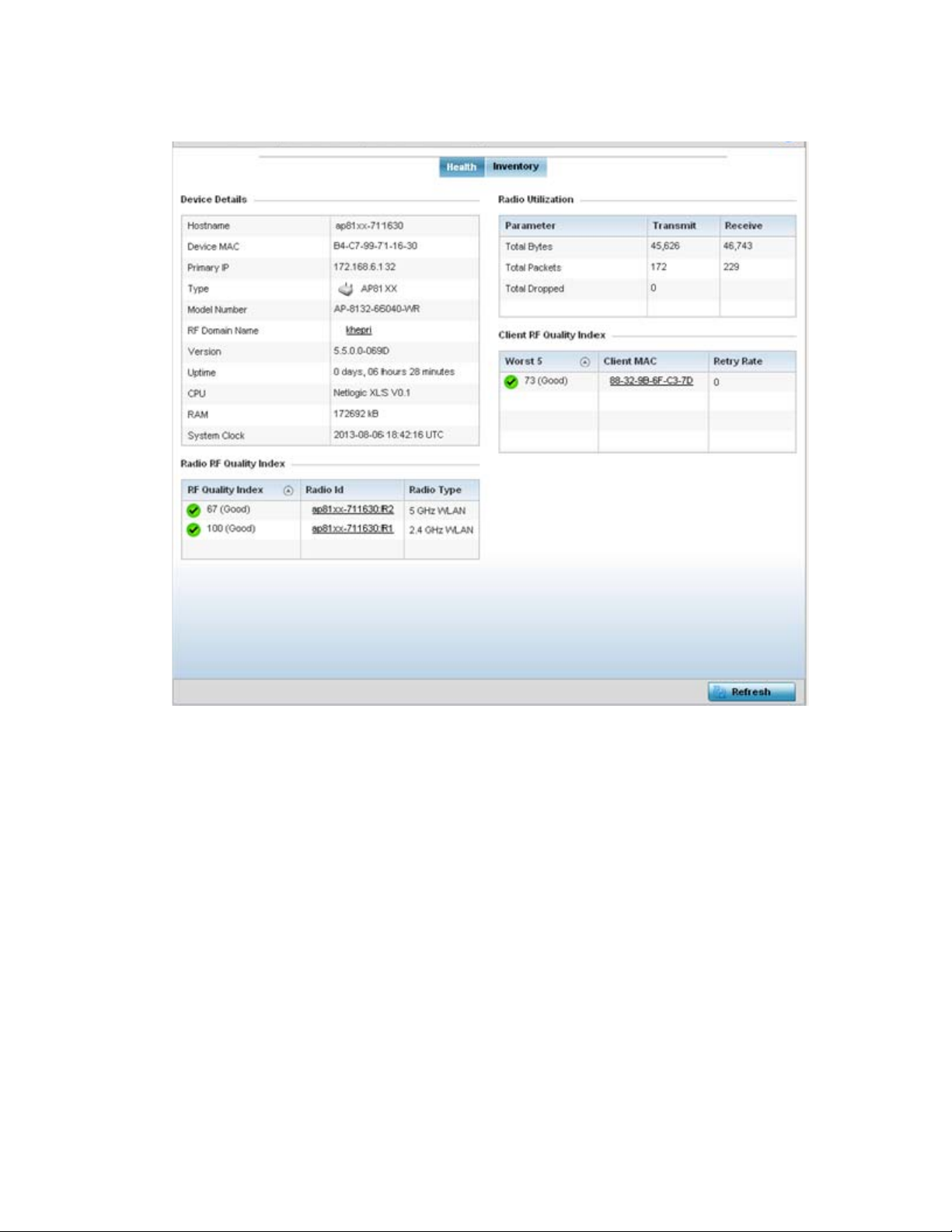
4
FIGURE 9 Access Point screen - Health tab
The Device Detail field displays the following information about the selected Access Point:
• Hostname - Lists the administrator assigned name of the selected Access Point.
• Device MAC - Lists the factory encoded MAC address of the selected Access Point.
• Primary IP Address - Lists the IP address assigned to the Access Point as a network identifier.
• Typ e - Indicates the Access Point model type. An icon representing the Access Point is
displayed along with the model number.
• RF Domain Name - Lists the RF Domain to which the Access Point belongs. The RF Domain
displays as a link that can be selected to display Access Point RF Domain membership data in
greater detail.
• Model Number - Lists the specific model number of the Access Point.
• Version - Lists the version of the firmware running on the Access Point. Compare this version
against the version currently on the support site to ensure the Access Point has the latest
feature set available.
• Uptime - Displays the duration the Access Point has been running from the time it was last
restarted.
• CPU - Displays the CPU installed on this Access Point.
38 Brocade Mobility RFS Controller System Reference Guide
53-1003099-01
Page 51

4
• RAM - Displays the amount of RAM available for use in this system.
• System Clock - Displays the current time on the Access Point.
The Radio RF Quality Index displays a table of RF quality per radio. It is a measure of the overall
effectiveness of the RF environment displayed in percentage. It is a function of the connect rate in
both directions, the retry rate and error rate. The quality is measured as:
• 0-20 - Very poor quality
• 20-40 - Poor quality
• 40-60 - Average quality
• 60-100 - Good quality
The Radio Utilization Index area displays how efficiently the RF medium is used. Radio utilization is
defined as the percentage of current throughput relative to the maximum possible throughput for
the radio. The Radio Utilization displays radios in terms of the number of associated wireless
clients and percentage of utilization. It also lists packets types transmitted and received.
The Client RF Quality Index displays a table of RF quality on a per client basis. It is a measure of the
overall effectiveness of the RF environment displayed in percentage. It is a function of the connect
rate in both directions, the retry rate and the error rate. This area of the screen displays the average
quality index for a client. The table lists bottom five (5) of the RF quality values by client. The quality
is measured as:
• 0-20 - Very poor quality
• 20-40 - Poor quality
• 40-60 - Average quality
• 60-100 - Good quality
Access Point Inventory
The Access Point Inventory tab displays granular data on devices managed by the selected Access
Point. Information is displayed in easy to read tables and graphs.
To assess Access Point network health:
1. Select Dashboard.
2. Select Summary if its not already selected by default.
3. Expand the System node to display RF Domains.
4. Select and expand a RF Domain to expose its member controllers or service platforms.
5. Select a controller or service platform and expand the menu item to display connected Access
Points.
6. Select an Access Point.
7. Select the Inventory tab.
Brocade Mobility RFS Controller System Reference Guide 39
53-1003099-01
Page 52
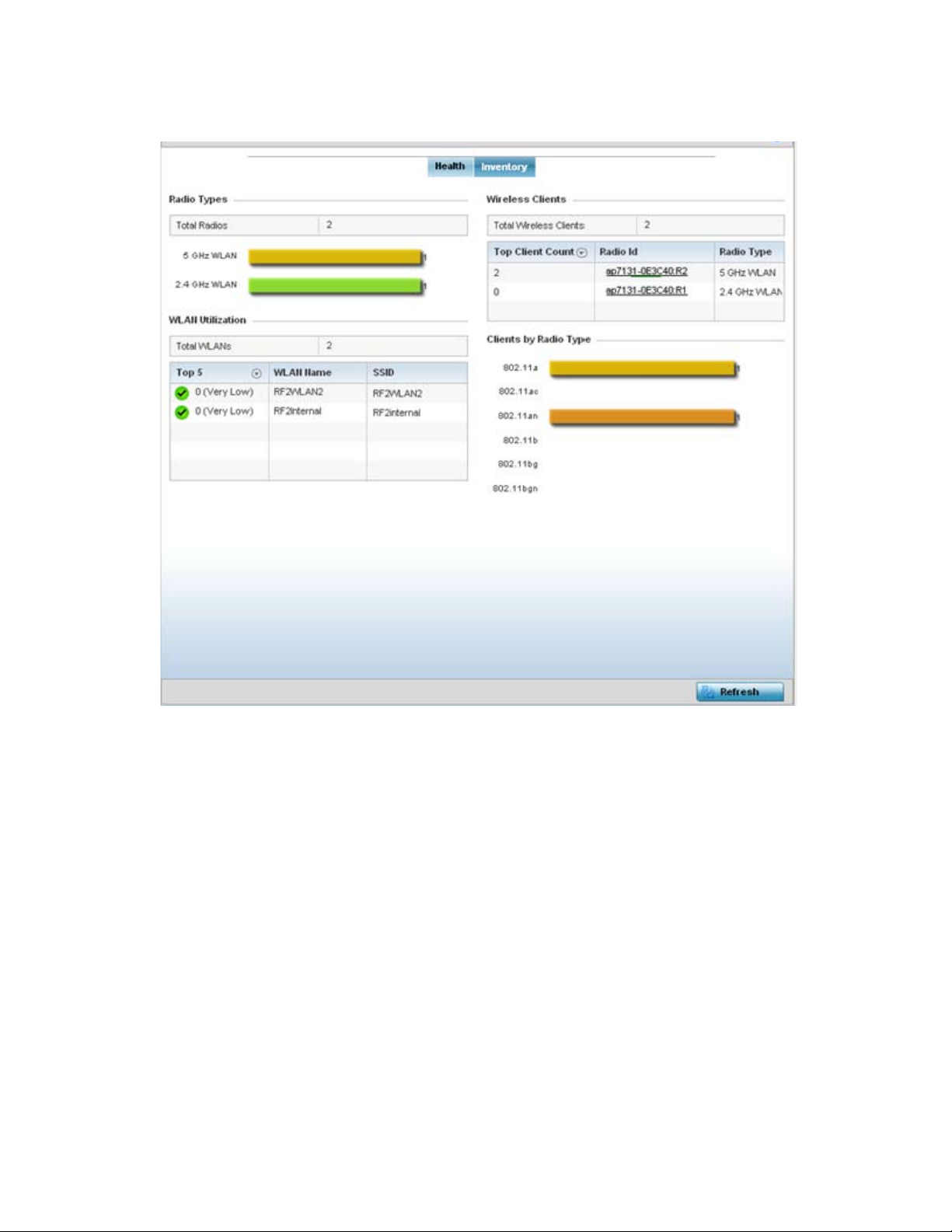
4
FIGURE 10 Access Point screen - Inventory tab
The information within the Inventory tab is partitioned into the following fields:
• The Radios Type field displays the total number of radios utilized by this Access Point. The
graph lists the number of radios in both the 2.4 GHz and 5 GHz radio bands.
• The WLAN Utilization table displays utilization statistics for controller or service platform WLAN
configurations. Information displays in two tables. The first table lists the total number of
WLANs managed by this system. The second table lists the top five (5) WLANs in terms of the
usage percentage along with their name and network identifying SSID.
• The Wireless Clients table lists clients managed by this Access Point by connected client count.
Information is presented in two (2) tables and a graph. The first table lists the total number of
clients managed by the listed Access Point. The second lists the top five (5) radios in terms of
the number of connected clients. The graph just below the table lists the number of clients by
radio type.
40 Brocade Mobility RFS Controller System Reference Guide
53-1003099-01
Page 53

Network View
4
The Network View functionality displays device association connectivity amongst controllers,
service platforms, Access Point radios and wireless clients. This association is represented by a
number of different graphs.
To review the wireless controller’s Network Topology, select Dashboard > Network View.
FIGURE 11 Network View Topology
• The screen displays icons for the different views available to the system. Apart from device
specific icons, the following three icons are available:
• default – Displays information about the default RF Domain.
• system – Displays information about the current system.
• cluster – Displays information about clusters managed by this system.
• Use the icons to navigate quickly within top level groupings.
• The middle field displays a Network View, or graphical representation of the network. Nodes
display whether or not they are members of a cluster or mesh domain. Use this information to
assess whether the topology of the network has changed in such a manner that devices need
to be added or moved. This field changes to display a graphical network map.
Brocade Mobility RFS Controller System Reference Guide 41
53-1003099-01
Page 54

4
• Use the Lock / Unlock icon in the upper right of the screen to prevent users from moving APs
around within the specified area.
42 Brocade Mobility RFS Controller System Reference Guide
53-1003099-01
Page 55

Chapter
Device Configuration
Managed devices can either be assigned unique configurations or have existing RF Domain or
Profile configurations modified (overridden) to support a requirement that dictates a device’s
configuration be customized from the configuration shared by its profiled peer devices.
When a device is initially managed by the controller or service platform, it requires several basic
configuration parameters be set (system name, deployment location etc.). Additionally, the number
of permitted device licenses (purchased directly from Brocade) needs to be accessed to determine
whether a new Access Point can be adopted.
Refer to the following to set a device’s basic configuration, license and certificate usage:
• Basic Configuration
• Basic Device Configuration
• License Configuration
• Assigning Certificates
RF Domains allow administrators to assign configuration data to multiple devices deployed in a
common coverage area (floor, building or site). In such instances, there’s many configuration
attributes these devices share as their general client support roles are quite similar. However,
device configurations may need periodic refinement (overrides) from their original RF Domain
administered design. For more information, see RF Domain Overrides.
5
Profiles enable administrators to assign a common set of configuration parameters and policies to
controller or service platforms and Access Points. Profiles can be used to assign shared or unique
network, wireless and security parameters to wireless controllers and Access Points across a large,
multi segment, site. The configuration parameters within a profile are based on the hardware
model the profile was created to support. The controller and service platform supports both default
and user defined profiles implementing new features or updating existing parameters to groups of
controllers, service platforms or Access Points.
However, device profile configurations may need periodic refinement from their original
administered configuration. Consequently, a device profile could be applied an override from the
configuration shared amongst numerous peer devices deployed within a particular site. For more
information, see Profile Overrides.
Adoption is the process an Access Point uses to discover controller or service platforms available in
the network, pick the most desirable, establish an association, obtain its configuration and
consider itself provisioned.
At adoption, an Access Point solicits and receives multiple adoption responses from available
controllers or service platforms on the network. Modify existing adoption policies or create a new
one as needed to meet the adoption requirements of a device and its assigned profile. For more
information, see Auto Provisioning Policies.
Brocade Mobility RFS Controller System Reference Guide 43
53-1003099-01
Page 56
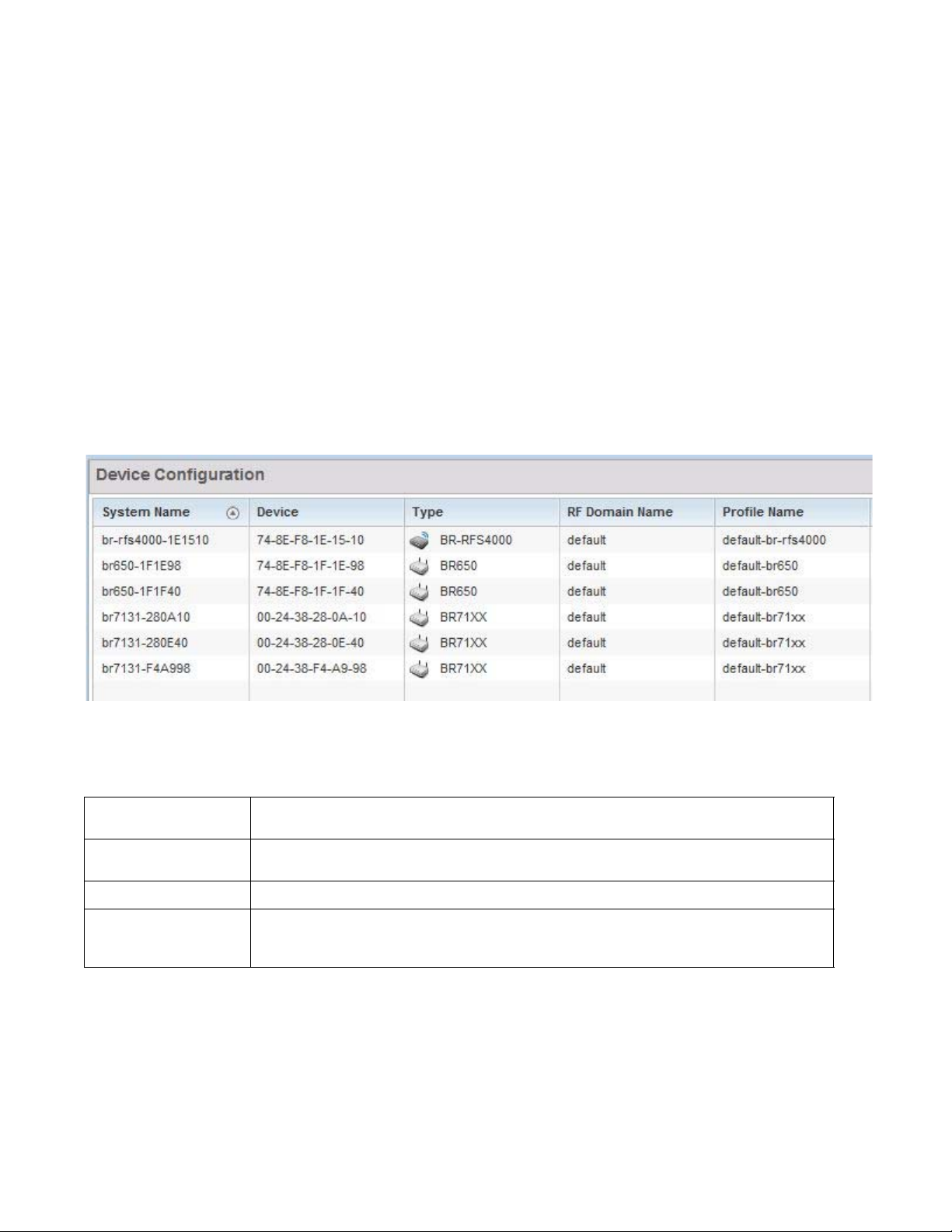
5
Lastly, use Configuration > Devices to define and manage a critical resource policy. A critical
resource policy defines a list of device IP addresses on the network (gateways, routers etc.). The
support of these IP address is interpreted as critical to the health of the network. These devices
addresses are pinged regularly by the controller or service platform. If there’s a connectivity issue,
an event is generated stating a critical resource is unavailable. For more information, see
Overriding a Profile’s Critical Resource Configuration.
Basic Configuration
To assign a Basic Configuration:
1. Select the Configuration tab from the Web UI.
2. Select Devices from the Configuration tab.
The Device Configuration screen displays a list of devices.
FIGURE 1 Device Configuration screen
Refer to the following device settings to determine whether a configuration update or RF
Domain or Profile change is warranted:
System Name
Device
Typ e
RF Domain Name
44 Brocade Mobility RFS Controller System Reference Guide
Displays the name assigned to the device when the basic configuration was defined. This is also the
device name that appears within the RF Domain or Profile the device supports.
Displays the device’s factory assigned MAC address used as hardware identifier. The MAC address
cannot be revised with the device’s configuration.
Displays the Brocade device model for the listed controller, service platform or Access Point.
Lists RF Domain memberships for each listed device. Devices can either belong to a default RF Domain
based on model type, or be assigned a unique RF Domain supporting a specific configuration
customized to that device model.
53-1003099-01
Page 57

5
NOTE
Profile Name
Area
Floor
Overrides
Lists the profile each listed device is currently a member of. Devices can either belong to a default
profile based on model type, or be assigned a unique profile supporting a specific configuration
customized to that model.
List the physical area where the controller or service platform is deployed. This can be a building,
region, campus or other area that describes the deployment location.
List the building Floor name representative of the location within the area or building the controller or
service platform was physically deployed. Assigning a building Floor name is helpful when grouping
devices in RF Domains and Profiles, as devices on the same physical building floor may need to share
specific configuration parameters in respect to radio transmission and interference requirements
specific to that location.
The Overrides column contains an option to clear all profile overrides for any devices that contain
overrides. To clear an override, select the clear button to the right of the device.
3. Select Add to create a new device, select Edit to modify an existing device or select Delete to
remove an existing device.
Basic Device Configuration
Setting a device’s Basic Configuration is required to assign a device name, deployment location,
and system time. Similarly, the Basic Configuration screen is where Profile and RF Domain
assignments are made. RF Domains allow administrators to assign configuration data to multiple
devices deployed in a common coverage area, such as in a floor, building or site. Each RF Domain
contains policies that can determine a Smart RF or WIPS configuration.
Profiles enable administrators to assign a common set of configuration parameters and policies to
controllers, service platforms and Access Points. Profiles can be used to assign common or unique
network, wireless and security parameters to wireless controllers and Access Points across a large,
multi segment, site. The configuration parameters within a profile are based on the hardware
model the profile was created to support. A controller and service platform support both default
and user defined profiles implementing new features or updating existing parameters to groups of
peer devices and Access Points. The central benefit of a profile is its ability to update devices
collectively without having to modify individual device configurations one at a time.
Once devices have been assigned membership in either a profile or RF Domain, an administrator
must be careful not to assign the device a configuration update that removes it from membership
from a RF Domain or profile. A RF Domain or profile configuration must be re-applied to a device
once its configuration has been modified in a manner that differentiates it from the configuration
shared by the devices comprising the RF Domain or profile.
To assign a device a Basic Configuration:
1. Select the Configuration tab from the Web UI.
2. Select Devices from the Configuration tab.
The Device Configuration screen displays a list of managed devices or peer controllers, service
platforms or Access Points.
3. Select a target device (by double-clicking it) from amongst those displayed.
Devices can also be selected directly from the Device Browser in the lower, left-hand, side of
the UI.
Brocade Mobility RFS Controller System Reference Guide 45
53-1003099-01
Page 58

5
4. The Basic Configuration screen displays by default.
FIGURE 2 Basic Configuration screen
5. Set the following Configuration settings for the target device:
System Name
Area
46 Brocade Mobility RFS Controller System Reference Guide
Provide the selected device a system name up to 64 characters. This is the device name that appears
within the RF Domain or Profile the device supports.
Assign the device an Area name representative of the location the controller or service platform was
physically deployed. The name cannot exceed 64 characters. Assigning an area name is helpful when
grouping devices in RF Domains and profiles, as devices in the same physical deployment location may
need to share specific configuration parameters in respect to radio transmission and interference
requirements specific to that location.
53-1003099-01
Page 59

5
NOTE
Floor
Floor Number
Latitude Coordinate
Longitude Coordinate
Assign the target a device a building Floor name representative of the location the Access Point was
physically deployed. The name cannot exceed 64 characters. Assigning a building Floor name is helpful
when grouping devices within the same general coverage area.
Use the spinner control to assign a numerical floor designation in respect to the floor’s actual location
within a building. Set a value from 1 - 4094. the default setting is the 1st floor.
Set the latitude coordinate where devices are deployed within a floor. When looking at a floor map,
latitude lines specify the east-west position of a point on the Earth's surface. The exact location of a
device deployment can be ascertained by aligning the latitude and longitude points on the earth’s
surface.
Set the longitude coordinate where devices are deployed within a floor. When looking at a floor map,
longitude lines specify the north-south position of a point on the Earth's surface. The exact location of a
device deployment can be ascertained by aligning the longitude and latitude points on the earth’s
surface.
6. Use the RF Domain drop-down menu to select an existing RF Domain for device membership.
If a RF Domain configuration does not exist suiting the deployment requirements of the target
device, select the Create icon to create a new RF Domain configuration, or select the Edit icon
to modify the configuration of a selected RF Domain. For more information, see About RF
Domains or Managing RF Domains.
7. Use the Profile drop-down menu to select an existing RF Domain for device membership.
If a profile configuration does not exist suiting the deployment requirements of the target device,
select the Create icon to create a new profile configuration, or select the Edit icon to modify the
configuration of a selected profile. For more information, see General Profile Configuration.
8. If necessary, select the Clear Overrides button to remove all existing overrides from the device.
9. Refer to the Set Clock parameter to update the system time of the target device.
Refer to the Device Time parameter to assess the device’s current time, or whether the
device time is unavailable. Select Refresh as required to update the device’s reported
system time.
Use the New Time parameter to set the calendar day, hour and minute for the target
device. Use the AM and PM radio buttons to refine whether the updated time is for the
morning or afternoon/evening.
When completed, select Update Clock to commit the updated time to the target device.
10. Select OK to save the changes made to the device’s Basic Configuration. Selecting Reset
reverts the screen to its last saved configuration.
License Configuration
Licenses are purchased directly from Brocade for the number of permissible adoptions per
controller, service platform or managed cluster.
The Licenses screen is only available to wireless controllers capable of sustaining device
connections, and thus requires license support to set the maximum number of allowed device
connections. The License screen is not available for Access Points.
Brocade Mobility RFS Controller System Reference Guide 47
53-1003099-01
Page 60

5
NOTE
Managing Brocade infrastructure devices requires a license key to enable software functionality or
define the number of adoptable devices permitted. My Licenses is a Web based online application
enabling you to request a license key for license certificates purchased for Brocade products.
For detailed instructions on using My Licenses to add hardware or software licenses and register
certificates, refer to the My Licenses Users Guide, available at
https://MyLicenses.motorolasolutions.com.
The Licenses screen also contains a facility where new licenses can be applied to increase the
number of device adoptions permitted, or to allow the use of the advanced security or advanced
WIPS features.
Each controller and service platform family has multiple models to choose from that range from
zero licenses to the maximum number that can be loaded for that specific SKU.
To configure a device’s a license configuration:
1. Select the Configuration tab from the Web UI.
2. Select Devices from the Configuration tab.
The Device Configuration screen displays a list of managed devices or peer controllers, service
platforms or Access Points.
3. Select a target device (by double-clicking it) from amongst those displayed within the Device
Configuration screen.
Devices can also be selected directly from the Device Browser in the lower, left-hand, side of
the UI.
4. Select Licenses from the Device menu options.
48 Brocade Mobility RFS Controller System Reference Guide
53-1003099-01
Page 61

5
NOTE
FIGURE 3 Device Licenses screen
The License screen displays the Device Serial Number of the controller or service platform
generating the license key.
When assessing lent and borrowed license information, its important to distinguish between site
controllers and NOC controllers.
NOC controllers are RFS9510, RFS6000 and RFS7000.
Site controllers are RFS4000, RFS6000 and RFS7000.
Brocade Mobility RFS Controller System Reference Guide 49
53-1003099-01
Page 62

5
NOTE
5. Review the AP Licenses table to assess the specific number of adoptions permitted, as
dictated by the terms of the current license.
AP Adoptions
AP Licenses
AP Lent Licenses
AP Borrowed Licenses
AP Total Licenses
The Device column Lists the total number of AP adoptions made by the controller or service platform. If
the installed license count is 10 APs and the number of AP adoptions is 5, 5 additional APs can still be
adopted under the terms of the license. The total number of APs adoptions varies by platform, as well
as the terms of the license. The Cluster column lists the total number of AP adoptions made by the
cluster membership (all members). If the installed license count is 100 APs and the number of AP
adoptions is 50, 50 additional APs can still be adopted under the terms of the AP licenses, pooled by
the cluster members.
The Device column lists the number of APs available for adoption under the restrictions of the license.
This number applies to dependent mode adaptive APs only, and not independent mode APs. The
Cluster column lists the number of APs available for adoption by cluster members under the restrictions
of the licenses, as pooled amongst the cluster members.
Lent licenses are the total number of AP licenses the NOC controller lends (if needed) to its site
controllers so site controllers can adopt APs in excess of its own installed AP license count. AP lent
licenses can be non-zero only in controllers currently configured as the NOC (NOC controller). Lent
Licenses is always zero in controllers configured as the site (site controller).
Borrowed licenses are the total number of AP licenses borrowed by the site controller from the NOC
controller (NOC controllers if a NOC controller is in a cluster). AP borrowed licenses are always zero in
the NOC controller. AAP borrowed licenses can be non-zero only on site controllers.
Lists the cumulative number of both Device and Cluster AP licenses supported by the listed controller or
service platform.
The following is a licensing example: Assume there's two site controllers (S1 and S2) adopted to a
NOC controller (N1). S1 has 3 installed AP licenses, and S2 has 4 installed AP licenses. Eight APs
seek to adopt on S1, and ten APs seek to adopt on S2. N1 has 1024 installed licenses. N1 lends 5
(8-3) AP licenses to S1, and 6 (10-4) AP licenses to S2.
N1 displays the following in the Device column: AP Adoptions: 2 (site controllers S1 and S2) AP
Licenses: 1024 AP Lent Licenses: 11 (5 to S1 + 6 to S2) AP Borrowed Licenses: 0 AP Total Licenses:
1013 (1024 – 11 lent) S1 displays the following in the Device column: AP Adoptions: 8 AP Licenses:
3 AP Lent Licenses: 0 AP Borrowed Licenses: 5 AP Total Licenses: 8 (3 + 5 borrowed). S2 displays
the following in the Device column: AP Adoptions: 10 AP Licenses: 4 AP Lent Licenses: 0 AP
Borrowed Licenses: 6 AP Total Licenses: 10 (4 + 6 borrowed).
50 Brocade Mobility RFS Controller System Reference Guide
53-1003099-01
Page 63

6. Review the AAP Licenses table to assess the specific number of adoptions permitted, as
dictated by the terms of the current license.
5
AAP Adoptions
AAP Licenses
AAP Lent Licenses
AAP Borrowed Licenses
AAP Total Licenses
7. Ref e r to t he Security Licenses field to apply licenses and provision advanced security and
Advanced Security
Advanced WIPS
Licenses
Analytics Licenses
Smart Cache Licenses
The Device column Lists the total number of AAP adoptions made by the controller or service platform.
If the installed license count is 10 APs and the number of AAP adoptions is 5, 5 additional AAPs can still
be adopted under the terms of the license. The total number of AAPs adoptions varies by platform, as
well as the terms of the license. The Cluster column lists the total number of AAP adoptions made by
the cluster membership (all members). If the installed license count is 100 APs and the number of AAP
adoptions is 50, 50 additional AAPs can still be adopted under the terms of the AAP licenses, pooled by
the cluster members.
The Device column lists the number of AAPs available for adoption under the restrictions of the license.
This number applies to dependent mode adaptive AAPs only, and not independent mode AAPs. The
Cluster column lists the number of AAPs available for adoption by cluster members under the
restrictions of the licenses, as pooled amongst the cluster members.
Lent licenses are the total number of AAP licenses the NOC controller lends (if needed) to its site
controllers so site controllers can adopt adaptive APs in excess of its own installed AAP license count.
AAP lent licenses can be non-zero only in controllers currently configured as the NOC (NOC controller).
Lent Licenses is always zero in controllers configured as the site (site controller).
Borrowed licenses are the total number of AAP licenses borrowed by the site controller from the NOC
controller (NOC controllers if a NOC controller is in a cluster). AAP borrowed licenses are always zero in
the NOC controller. AAP borrowed licenses can be non-zero only on site controllers.
Lists the cumulative number of both Device and Cluster AAP licenses supported by the listed controller
or service platform.
analytics features:
Enter the Brocade provided license key required to install the Role Based Firewall feature and increase
the number of IPSec VPN tunnels. The number of IPSec tunnels varies by platform.
Enter the Brocade provided license key required to install Advanced WIPS for client terminations and
event sanctioning.
Enter the Brocade provided license key required to install Analytics (an enhanced statistical
management tool) for NX4500, NX6500 and NX9000 series service platforms.
Enter the Brocade provided license key required to install the Smart Cache feature on a supported
service platform. Smart Caching is used on NX4500 and NX6500 series service platforms to
temporarily store frequently accessed Web content (Web pages, graphics, audio and video files etc.) on
network infrastructure devices. When this content is requested, its retrieved from a local content cache
and not from the origin server. Smart caching results in reduced bandwidth usage, lower latency
periods and reduced data transfers from the origin servers. Both forward caching and transparent
caching are supported.
8. Select OK to save the changes made to the applied licenses. Selecting Reset reverts the
screen to its last saved configuration.
Assigning Certificates
A certificate links identity information with a public key enclosed in the certificate.
Brocade Mobility RFS Controller System Reference Guide 51
53-1003099-01
Page 64
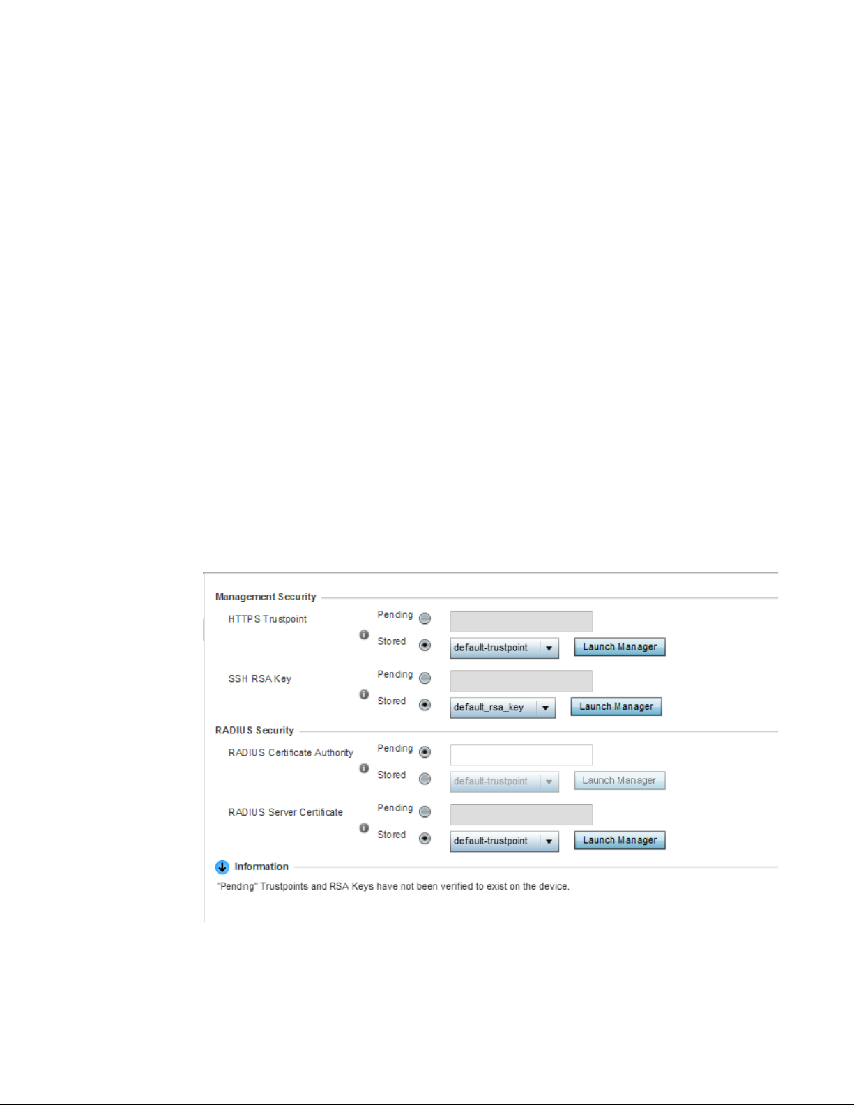
5
A certificate authority (CA) is a network authority that issues and manages security credentials and
public keys for message encryption. The CA signs all digital certificates it issues with its own private
key. The corresponding public key is contained within the certificate and is called a CA certificate. A
browser must contain the CA certificate in its Trusted Root Library so it can trust certificates signed
by the CA's private key.
Depending on the public key infrastructure, the digital certificate includes the owner's public key,
the certificate expiration date, the owner's name and other public key owner information.
Each certificate is digitally signed by a trustpoint. The trustpoint signing the certificate can be a
certificate authority, corporation or individual. A trustpoint represents a CA/identity pair containing
the identity of the CA, CA-specific configuration parameters, and an association with an enrolled
identity certificate.
SSH keys are a pair of cryptographic keys used to authenticate users instead of, or in addition to, a
username/password. One key is private and the other is public key. Secure Shell (SSH) public key
authentication can be used by a requesting client to access resources, if properly configured. A RSA
key pair must be generated on the client. The public portion of the key pair resides with the
controller or service platform, while the private portion remains on a secure local area of the client.
To configure certificate usage:
1. Select the Configuration tab from the Web UI.
2. Select Devices from the Configuration tab.
The Device Configuration screen displays a list of managed devices or peer controllers, service
platforms or Access Points.
3. Select Certificates from the Device menu.
FIGURE 4 Device Certificates screen
52 Brocade Mobility RFS Controller System Reference Guide
53-1003099-01
Page 65

4. Set the following Management Security certificate configurations:
NOTE
5
HTTPS Trustpoint
SSH RSA Key
RADIUS Certificate
Authority
RADIUS Server
Certificate
Either use the default trustpoint or select the Stored radio button to enable a drop-down menu where
an existing certificate/trustpoint can be utilized. To use an existing certificate for this device, select the
Launch Manager button. For more information, see
Certificate Management
Either use the default_rsa_key or select the Stored radio button to enable a drop-down menu where an
existing certificate can be used. To leverage an existing key, select the Launch Manager button. For
more information, see
RSA Key Management
Pending trustpoints and RSA keys are typically not verified as existing on a device.
5. Set the following RADIUS Security certificate configurations:
Either use the default-trustpoint or select the Stored radio button to enable a drop-down menu where
an existing certificate can be leveraged. To leverage an existing certificate, select the Launch Manager
button.
Either use the default-trustpoint or select the Stored radio button to enable a drop-down menu where
an existing certificate/trustpoint can be used. To leverage an existing trustpoint, select the Launch
Manager button.
6. Select OK to save the changes made to the certificate configurations. Selecting Reset reverts
the screen to its last saved configuration.
For more information on the certification activities supported, refer to the following:
• Certificate Management
• RSA Key Management
• Certificate Creation
• Generating a Certificate Signing Request
Certificate Management
Assigning Certificates
A stored certificate can be leveraged from a different managed device if not wanting to use an
existing certificate or key. Device certificates can be imported and exported to and from the
controller or service platform to a secure remote location for archive and retrieval as required for
other managed devices.
To configure trustpoints for use with certificates:
1. Select Launch Manager from either the HTTPS Trustpoint, SSH RSA Key, RADIUS Certificate
Authority or RADIUS Server Certificate parameters.
Brocade Mobility RFS Controller System Reference Guide 53
53-1003099-01
Page 66
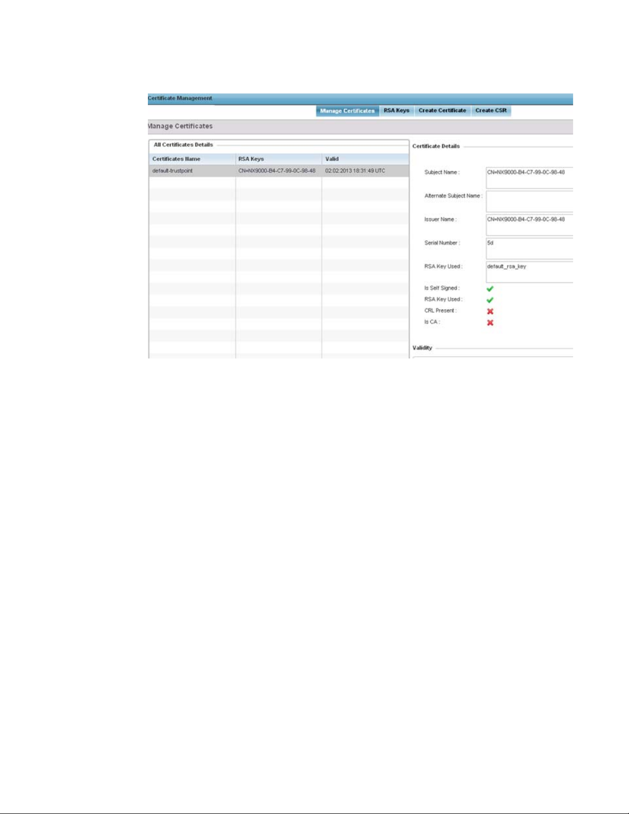
5
FIGURE 5 Certificate Management - Manage Certificates screen
The Certificate Management screen displays with the Manage Certificates tab displayed
by default.
2. Select a device from amongst those displayed to review its certificate information.
3. Refer to the All Certificate Details to review the certificate’s properties, self-signed credentials,
validity duration and CA information.
4. To optionally import a certificate, select the Import button from the Certificate Management
screen.
54 Brocade Mobility RFS Controller System Reference Guide
53-1003099-01
Page 67
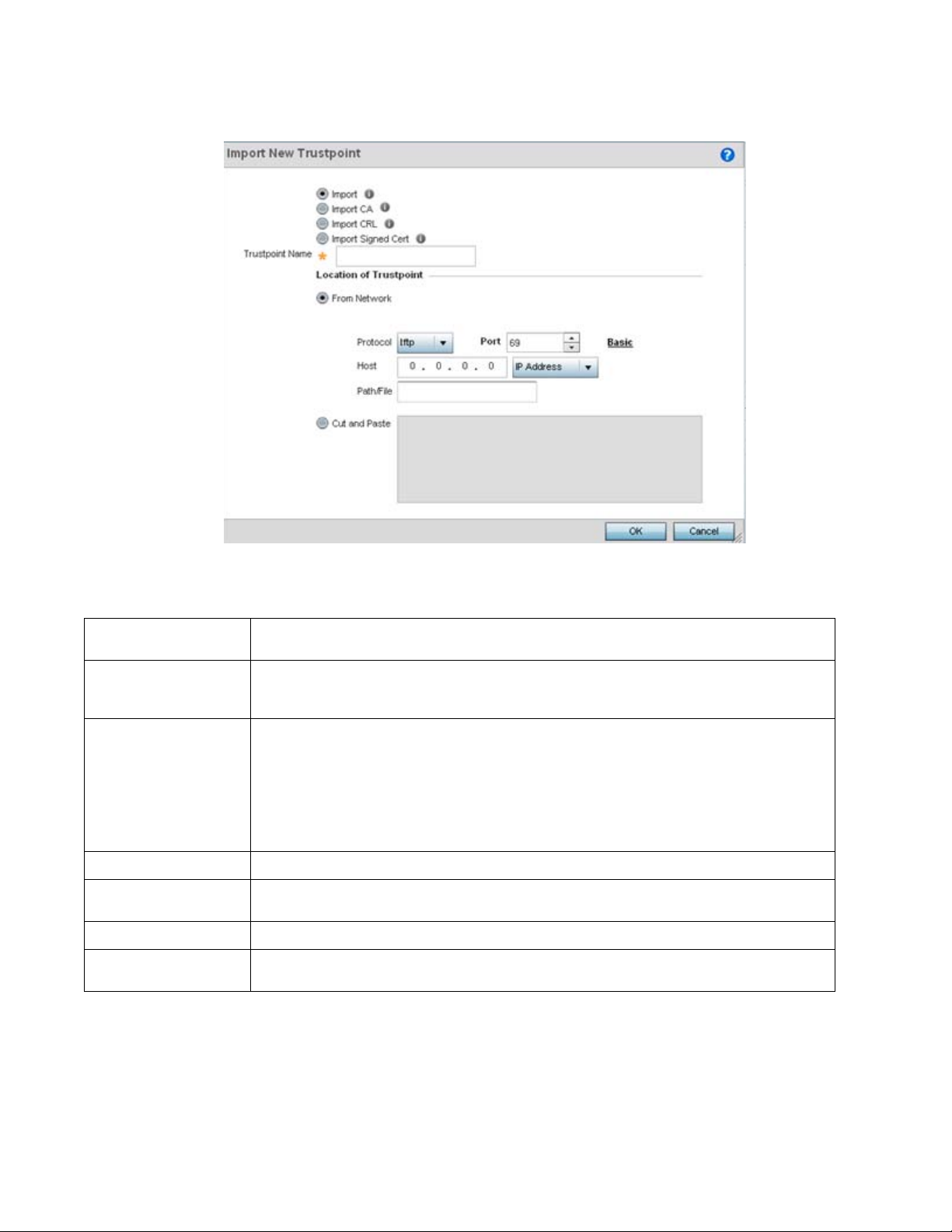
5
Tru s t p o i nt Name
URL
Protocol
Port
Host
Path/File
Cut and Paste
FIGURE 6 Certificate Management - Import New Trustpoint screen
5. Define the following configuration parameters required for the Import of the trustpoint.
Enter the 32 character maximum name assigned to the target trustpoint. The trustpoint signing the
certificate can be a certificate authority, corporation or individual.
Provide the complete URL to the location of the trustpoint. If needed, select Advanced to expand the
dialog to display network address information to the location of the target trustpoint. The number of
additional fields that populate the screen is also dependent on the selected protocol.
Select the protocol used for importing the target trustpoint. Available options include:
tftp
ftp
sftp
http
cf
usb1-4
Use the spinner control to set the port. This option is not valid for cf and usb1-4.
Provide the hostname string or numeric IP address of the server used to import the trustpoint. This
option is not valid for cf and usb1-4.
Specify the path to the trustpoint file. Enter the complete relative path to the file on the server.
Select the Cut and Paste radio button to simply copy an existing trustpoint into the cut and past field.
When pasting, no additional network address information is required.
6. Select OK to import the defined trustpoint. Select Cancel to revert the screen to its last saved
configuration.
7. To optionally import a CA certificate, select the Import CA button from the Certificate
Management screen.
Brocade Mobility RFS Controller System Reference Guide 55
53-1003099-01
Page 68
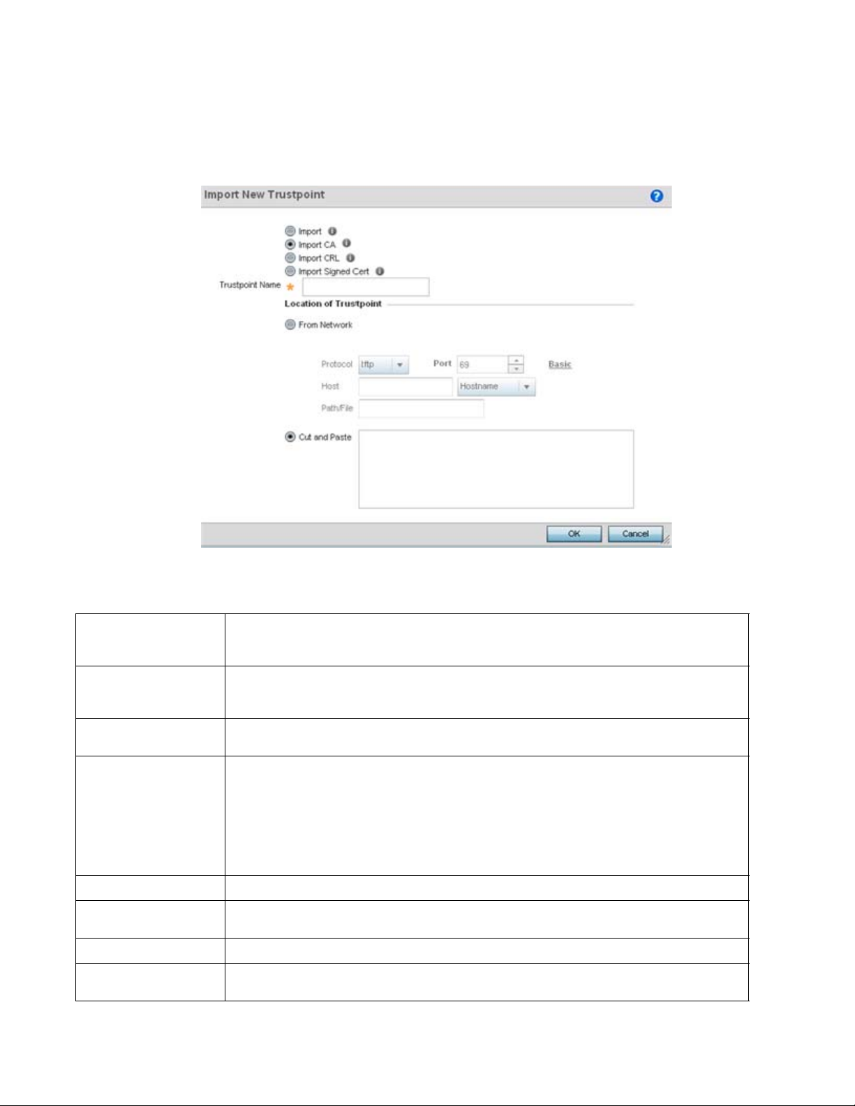
5
A CA is a network authority that issues and manages security credentials and public keys for
message encryption. The CA signs all digital certificates it issues with its own private key. The
corresponding public key is contained within the certificate and is called a CA certificate.
Tru s t p o i nt Name
URL
Advanced / Basic
Protocol
Port
Host
Path/File
Cut and Paste
FIGURE 7 Certificate Management - Import CA Certificate screen
8. Define the following configuration parameters required for the Import of the CA certificate:
Enter the 32 character maximum name assigned to the target trustpoint signing the certificate. A
trustpoint represents a CA/identity pair containing the identity of the CA, CA specific configuration
parameters, and an association with an enrolled identity certificate.
Provide the complete URL to the location of the trustpoint. If needed, select Advanced to expand the
dialog to display network address information to the location of the target trustpoint. The number of
additional fields populating the screen is dependent on the selected protocol.
Click the Advanced or Basic link to switch between a basic URL and an advanced location to specify
trustpoint location.
Select the protocol used for importing the target CA certificate. Available options include:
tftp
ftp
sftp
http
cf
usb1-4
Use the spinner control to set the port. This option is not valid for cf and usb1-4.
Provide the hostname string or numeric IP address of the server used to import the CA. This option is
not valid for cf and usb1-4.
Specify the path to the CA file. Enter the complete relative path to the file on the server.
Select the Cut and Paste radio button to simply copy an existing CA into the cut and past field. When
pasting, no additional network address information is required.
56 Brocade Mobility RFS Controller System Reference Guide
53-1003099-01
Page 69
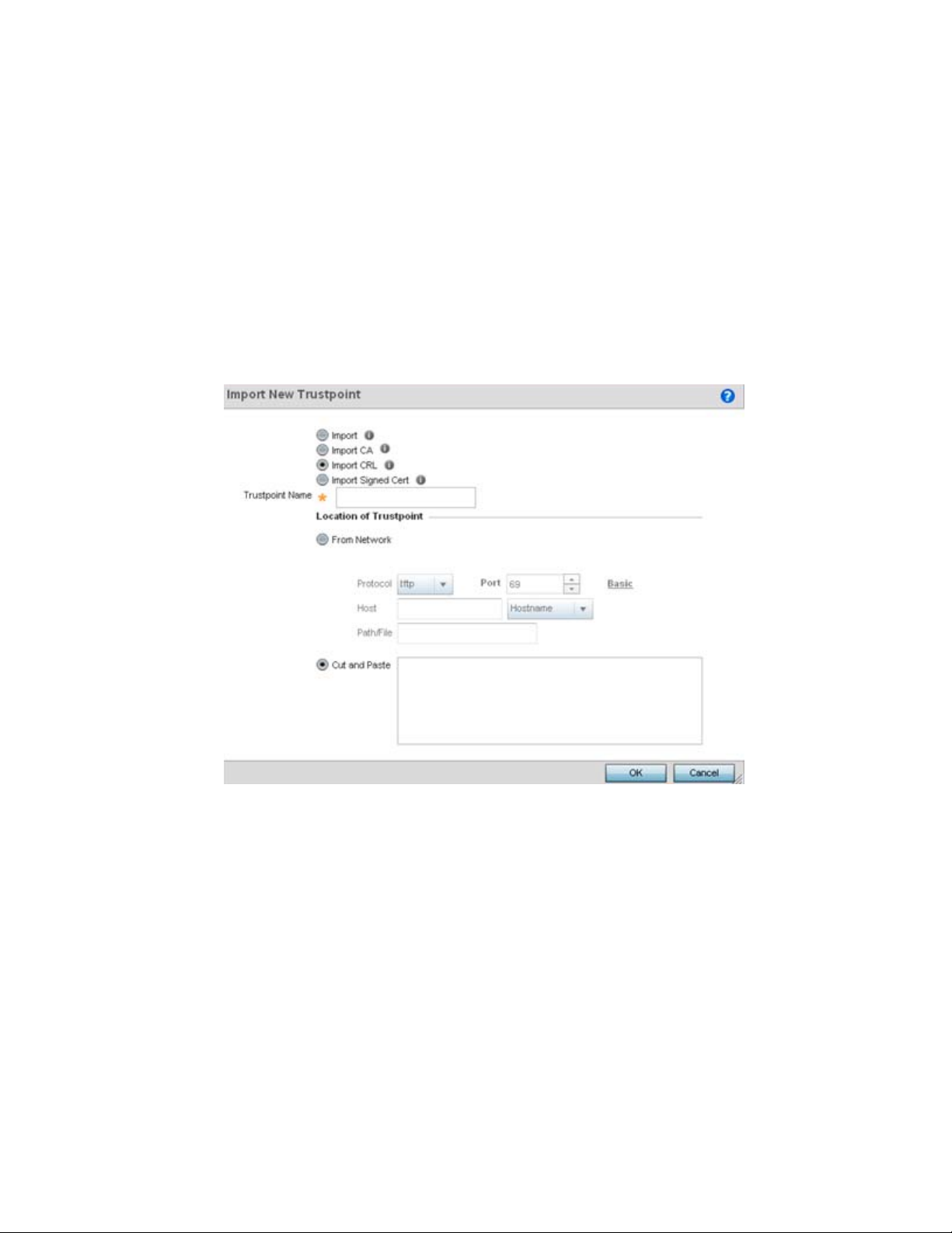
5
9. Select OK to import the defined CA certificate. Select Cancel to revert the screen to its last
saved configuration.
10. Select the Import CRL button from the Certificate Management screen to optionally import a
CRL to a controller or service platform.
If a certificate displays within the Certificate Management screen with a CRL, that CRL can
be imported. A certificate revocation list (CRL) is a list of certificates that have been
revoked or are no longer valid. A certificate can be revoked if the CA had improperly issued
a certificate, or if a private-key is compromised. The most common reason for revocation is
the user no longer being in sole possession of the private key.
For information on creating a CRL to use with a trustpoint, refer to Setting the Certificate
Revocation List (CRL) Configuration.
FIGURE 8 Certificate Management - Import CRL screen
Brocade Mobility RFS Controller System Reference Guide 57
53-1003099-01
Page 70

5
Define the following configuration parameters required for the Import of the CRL
Tru s t p o i nt Name
From Network
URL
Protocol
Port
Host
Path/File
Cut and Paste
Enter the 32 character maximum name assigned to the target trustpoint signing the certificate. A
trustpoint represents a CA/identity pair containing the identity of the CA, CA-specific configuration
parameters, and an association with an enrolled identity certificate.
Select the From Network radio button to provide network address information to the location of the
target CRL. The number of additional fields that populate the screen is also dependent on the selected
protocol. This is the default setting.
Provide the complete URL to the location of the CRL. If needed, select Advanced to expand the dialog to
display network address information to the location of the CRL. The number of additional fields that
populate the screen is also dependent on the selected protocol.
Select the protocol used for importing the CRL. Available options include:
tftp
ftp
sftp
http
cf
usb1-4
Use the spinner control to set the port. This option is not valid for cf and usb1-4.
Provide the hostname string or numeric IP address of the server used to import the CRL. This option is
not valid for cf and usb1-4.
Specify the path to the CRL file. Enter the complete relative path to the file on the server.
Select the Cut and Paste radio button to simply copy an existing CRL into the cut and past field. When
pasting, no additional network address information is required.
11. Select OK to import the CRL. Select Cancel to revert the screen to its last saved configuration.
12. To import a signed certificate, select the Import Signed Cert button from the Certificate
Management screen.
Signed certificates (or root certificates) avoid the use of public or private CAs. A self-signed
certificate is an identity certificate signed by its own creator, thus the certificate creator also
signs off on its legitimacy. The lack of mistakes or corruption in the issuance of self signed
certificates is central.
Self-signed certificates cannot be revoked which may allow an attacker who has already
gained access to monitor and inject data into a connection to spoof an identity if a private key
has been compromised. However, CAs have the ability to revoke a compromised certificate,
preventing its further use.
58 Brocade Mobility RFS Controller System Reference Guide
53-1003099-01
Page 71
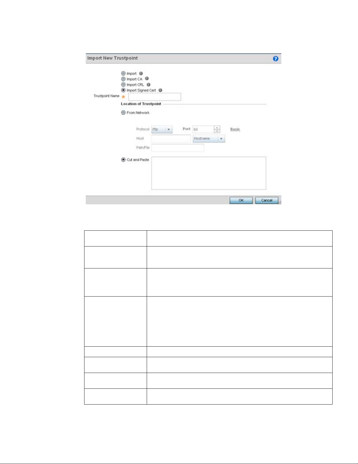
5
FIGURE 9 Certificate Management - Import Signed Cert screen
13. Define the following parameters required for the Import of the CA certificate:
Certificate Name
From Network
URL
Protocol
Port
Host
Path/File
Cut and Paste
Enter the 32 character maximum trustpoint name with which the certificate should be
associated.
Select the From Network radio button to provide network address information to the
location of the signed certificate. The number of additional fields that populate the
screen is dependent on the selected protocol. From Network is the default setting.
Provide the complete URL to the location of the signed certificate. If needed, select
Advanced to expand the dialog to display network address information to the location
of the signed certificate. The number of additional fields populating the screen is
dependent on the selected protocol.
Select the protocol for importing the signed certificate. Available options include:
tftp
ftp
sftp
http
cf
usb1-4
Use the spinner control to set the port. This option is not valid for cf and usb1-4.
Provide the hostname string or numeric IP address of the server used to import the
signed certificate. This option is not valid for cf and usb1-4.
Specify the path to the signed certificate file. Enter the complete relative path to the file
on the server.
Select the Cut and Paste radio button to simply copy an existing certificate into the cut
and past field. When pasting, no additional network address information is required.
Brocade Mobility RFS Controller System Reference Guide 59
53-1003099-01
Page 72
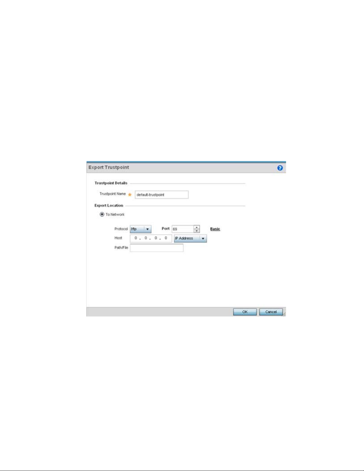
5
14. Select OK to import the signed certificate. Select Cancel to revert the screen to its last saved
configuration
15. To optionally export a trustpoint to a remote location, select the Export button from the
Certificate Management screen.
Once a certificate has been generated on the controller or service platform’s authentication
server, export the self signed certificate. A digital CA certificate is different from a self signed
certificate. The CA certificate contains the public and private key pairs. The self certificate only
contains a public key. Export the self certificate for publication on a Web server or file server
for certificate deployment or export it in to an active directory group policy for automatic root
certificate deployment.
16. Additionally export the key to a redundant RADIUS server so it can be imported without
generating a second key. If there’s more than one RADIUS authentication server, export the
certificate and don’t generate a second key unless you want to deploy two root certificates.
FIGURE 10 Certificate Management - Export Trustpoint screen
60 Brocade Mobility RFS Controller System Reference Guide
53-1003099-01
Page 73

17. Define the following configuration parameters required for the Export of the trustpoint.
5
Trustpoint Name
URL
Protocol
Port
Host
Path/File
Cut and Paste
Enter the 32 character maximum name assigned to the trustpoint. The trustpoint
signing the certificate can be a certificate authority, corporation or individual.
Provide the complete URL to the location of the trustpoint. If needed, select
Advanced to expand the dialog to display network address information to the
location of the trustpoint. The number of additional fields that populate the screen is
dependent on the selected protocol.
Select the protocol used for exporting the target trustpoint. Available options
include:
tftp
ftp
sftp
http
cf
usb1-4
Use the spinner control to set the port. This option is not valid for cf and usb1-4.
Provide the hostname string or numeric IP address of the server used to export the
trustpoint. This option is not valid for cf and usb1-4.
Specify the path to the signed trustpoint file. Enter the complete relative path to the
file on the server.
Select the Cut and Paste radio button to simply copy an existing trustpoint into the
cut and past field. When pasting, no additional network address information is
required.
18. Select OK to export the defined trustpoint. Select Cancel to revert the screen to its last saved
configuration.
19. To optionally delete a trustpoint, select the Delete button from within the Certificate
Management screen. Provide the trustpoint name within the Delete Trustpoint screen and
optionally select Delete RSA Key to remove the RSA key along with the trustpoint. Select OK to
proceed with the deletion, or Cancel to revert to the Certificate Management screen
RSA Key Management
Assigning Certificates
Refer to the RSA Keys screen to review existing RSA key configurations that have been applied to
managed devices. If an existing key does not meet the needs of a pending certificate request,
generate a new key or import/export an existing key to and from a remote location.
Rivest, Shamir, and Adleman (RSA) is an algorithm for public key cryptography. It’s an algorithm
that can be used for certificate signing and encryption. When a device trustpoint is created, the
RSA key is the private key used with the trustpoint.
To review existing device RSA key configurations, generate additional keys or import/export keys to
and from remote locations:
1. Select the Launch Manager button from either the SSH RSA Key, RADIUS Certificate Authority
or RADIUS Server Certificate parameters (within the Certificate Management screen).
2. Select RSA Keys from the upper, left-hand, side of the Certificate Management screen.
Brocade Mobility RFS Controller System Reference Guide 61
53-1003099-01
Page 74

5
FIGURE 11 Certificate Management - RSA Keys screen
3. Select a listed device to review its current RSA key configuration.
Each key can have its size and character syntax displayed. Once reviewed, optionally generate
a new RSA key, import a key from a selected device, export a key to a remote location or delete
a key from a selected device.
4. Select Generate Key to create a new key with a defined size.
62 Brocade Mobility RFS Controller System Reference Guide
53-1003099-01
Page 75

5
FIGURE 12 Certificate Management - Generate RSA Keys screen
5. Define the following configuration parameters required for the Import of the key:
Key Name
Key Size
Enter the 32 character maximum name assigned to the RSA key.
Use the spinner control to set the size of the key (from 1,024 - 2,048 bits). Brocade
recommends leaving this value at the default setting of 1024 to ensure optimum
functionality.
6. Select OK to generate the RSA key. Select Cancel to revert the screen to its last saved
configuration.
7. To optionally import a CA certificate, select the Import button from the Certificate Management
> RSA Keys screen.
Brocade Mobility RFS Controller System Reference Guide 63
53-1003099-01
Page 76

5
FIGURE 13 Certificate Management - Import New RSA Key screen
8. Define the following parameters required for the Import of the RSA key:
Key Name
Key Passphrase
URL
Advanced / Basic
Protocol
Port
Host
Path/File
Enter the 32 character maximum name assigned to identify the RSA key.
Define the key used by both the controller or service platform and the server (or
repository) of the target RSA key. Select the Show
in the passphrase. Leaving the Show unselected displays the passphrase as a series of
asterisks “*”.
Provide the complete URL to the location of the RSA key. If needed, select Advanced to
expand the dialog to display network address information to the location of the target
key. The number of additional fields that populate the screen is dependent on the
selected protocol.
Select either the Advanced or Basic link to switch between a basic URL and an
advanced location to specify key location.
Select the protocol used for importing the target key. Available options include:
tftp
ftp
sftp
http
cf
usb1-4
Use the spinner control to set the port. This option is not valid for cf and usb1-4.
Provide a text string hostname or numeric IP address of the server used to import the
RSA key. This option is not valid for cf and usb1-4.
Specify the path to the RSA key. Enter the complete relative path to the key on the
server.
to expose the actual characters used
64 Brocade Mobility RFS Controller System Reference Guide
53-1003099-01
Page 77

5
9. Select OK to import the defined RSA key. Select Cancel to revert the screen to its last saved
configuration.
10. To optionally export a RSA key to a remote location, select the Export button from the
Certificate Management > RSA Keys screen.
Export the key to a redundant RADIUS server to import it without generating a second key. If
there’s more than one RADIUS authentication server, export the certificate and don’t generate
a second key unless you want to deploy two root certificates.
FIGURE 14 Certificate Management - Export RSA Key screen
11. Define the following configuration parameters required for the Export of the RSA key.
Key Name
Key Passphrase
URL
Protocol
Port
Host
Path / File
Enter the 32 character maximum name assigned to the RSA key.
Define the key passphrase used by both the controller or service platform and the
server. Select Show
Leaving the Show unselected displays the passphrase as a series of asterisks “*”.
Provide the complete URL to the location of the key. If needed, select Advanced to
expand the dialog to display network address information to the location of the
target key. The number of additional fields that populate the screen is dependent
on the selected protocol.
Select the protocol used for exporting the RSA key. Available options include:
tftp
ftp
sftp
http
cf
usb1-4
Use the spinner control to set the port. This option is not valid for cf and usb1-4.
Provide a text string hostname or numeric IP address of the server used to export
the RSA key. This option is not valid for cf and usb1-4.
Specify the path to the key. Enter the complete relative path to the key on the
server.
to expose the actual characters used in the passphrase.
Brocade Mobility RFS Controller System Reference Guide 65
53-1003099-01
Page 78

5
12. Select OK to export the defined RSA key. Select Cancel to revert the screen to its last saved
configuration.
13. To optionally delete a key, select the Delete button from within the Certificate Management >
RSA Keys screen. Provide the key name within the Delete RSA Key screen and select Delete
Certificates to remove the certificate. Select OK to proceed with the deletion, or Cancel to
revert back to the Certificate Management screen.
Certificate Creation
Assigning Certificates
The Certificate Management screen provides the facility for creating new self-signed certificates.
Self signed certificates (often referred to as root certificates) do not use public or private CAs. A self
signed certificate is a certificate signed by its own creator, with the certificate creator responsible
for its legitimacy.
To create a self-signed certificate that can be applied to a managed device:
1. Select the Launch Manager button from either the SSH RSA Key, RADIUS Certificate Authority
or RADIUS Server Certificate parameters (within the Certificate Management screen).
2. Select Create Certificate from the upper, left-hand, side of the Certificate Management screen.
FIGURE 15 Certificate Management - Create Certificate screen
66 Brocade Mobility RFS Controller System Reference Guide
53-1003099-01
Page 79

5
3. Define the following configuration parameters required to Create New Self-Signed Certificate:
Certificate Name
RSA Key
Enter the 32 character maximum name assigned to identify the name of the
trustpoint associated with the certificate. A trustpoint represents a CA/identity pair
containing the identity of the CA, CA-specific configuration parameters, and an
association with an enrolled identity certificate.
Select a radio button and use the drop-down menu to set the key used by both the
controller or service platform and the server (or repository) of the target RSA key.
Optionally select Create New and enter a 32 character name used to identify the
RSA key. Use the spinner control to set the size of the key (from 1,024 - 2,048 bits).
Brocade recommends leaving this value at the default setting of 1024 to ensure
optimum functionality.
4. Set the following Certificate Subject Name parameters required for the creation of the
certificate:
Certificate Subject
Name
Country (C)
State (ST)
City (L)
Organization (O)
Organizational Unit
(OU)
Select either auto-generate to automatically create the certificate's subject
credentials or user-defined to manually enter the credentials of the self signed
certificate. The default setting is auto-generate.
Define the Country used in the certificate. The field can be modified by the user to
other values. This is a required field and must not exceed 2 characters.
Enter a State/Prov. for the state or province name used in the certificate. This is a
required field.
Enter a City to represent the city used in the certificate. This is a required field.
Define an Organization for the organization represented in the certificate. This is a
required field.
Enter an Org. Unit for the organization unit represented in the certificate. This is a
required field.
Common Name (CN)
If there’s a common name (IP address) for the organizational unit issuing the
certificate, enter it here.
5. Select the following Additional Credentials required for the generation of the self signed
certificate:
Email Address
Domain Name)
IP Address
Provide an Email Address used as the contact address for issues relating to this
certificate request.
Enter a fully qualified domain name (FQDN) is an unambiguous domain name that
specifies the node's position in the DNS tree hierarchy absolutely. To distinguish an
FQDN from a regular domain name, a trailing period is added. For example,
somehost.example.com. An FQDN differs from a regular domain name by its
absoluteness, since a suffix is not added.
Specify the IP address used as the destination for certificate requests.
6. Select the Generate Certificate button at the bottom of the Certificate Management > Create
Certificate screen to produce the certificate.
Generating a Certificate Signing Request
Assigning Certificates
Brocade Mobility RFS Controller System Reference Guide 67
53-1003099-01
Page 80
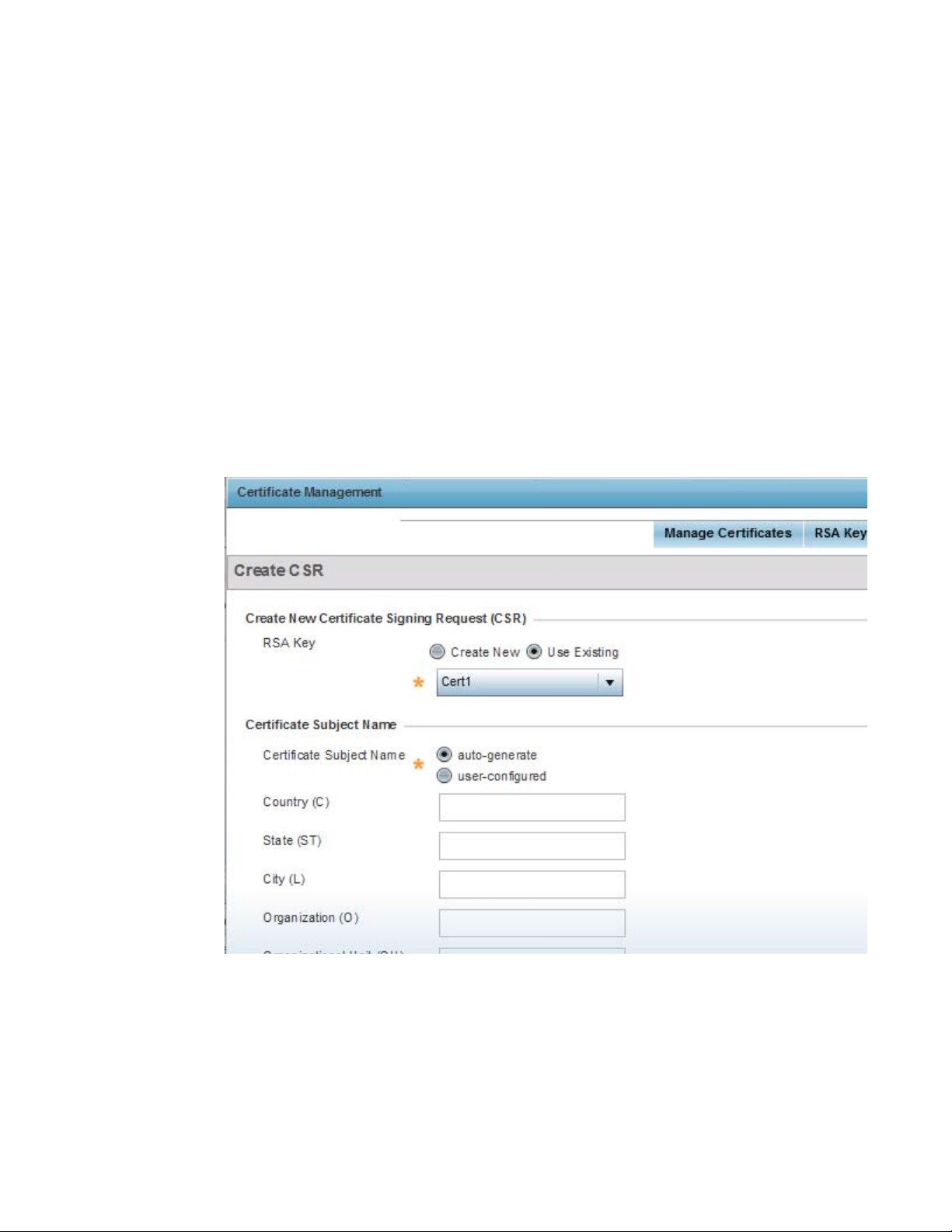
5
A certificate signing request (CSR) is a request to a certificate authority to apply for a digital identity
certificate. The CSR is a block of encrypted text generated on the server the certificate is used on.
It contains the organization name, common name (domain name), locality and country.
A RSA key must be either created or applied to the certificate request before the certificate can be
generated. A private key is not included in the CSR, but is used to digitally sign the completed
request. The certificate created with a particular CSR only works with the private key generated
with it. If the private key is lost, the certificate is no longer functional.The CSR can be accompanied
by other identity credentials required by the certificate authority, and the certificate authority
maintains the right to contact the applicant for additional information.
If the request is successful, the CA sends an identity certificate digitally signed with the private key
of the CA.
To cr e a te a CSR:
1. Select the Launch Manager button from either the SSH RSA Key, RADIUS Certificate Authority
or RADIUS Server Certificate parameters (within the Certificate Management screen).
2. Select Create CSR from the upper, left-hand, side of the Certificate Management screen.
FIGURE 16 Certificate Management - Create CSR screen
68 Brocade Mobility RFS Controller System Reference Guide
53-1003099-01
Page 81

3. Define the following configuration parameters required to Create New Certificate Signing
Request (CSR):
5
RSA Key
Select a radio button and use the drop-down menu to set the key used by both the
controller or service platform and the server (or repository) of the target RSA key.
Optionally select Create New to use new RSA key and provide a 32 character name
used to identify the RSA key. Use the spinner control to set the size of the key (from
1,024 - 2,048 bits). Brocade recommends leaving this value at the default setting of
1024 to ensure optimum functionality.
4. Set the following Certificate Subject Name parameters required for the creation of the
certificate:
Certificate Subject
Name
Country (C)
State (ST)
City (L)
Organization (O)
Organizational Unit
Select either the auto-generate radio button to automatically create the certificate's
subject credentials or user-defined to manually enter the credentials of the self
signed certificate. The default setting is auto-generate.
Define the Country used in the CSR. The field can be modified by the user to other
values. This is a required field and must not exceed 2 characters.
Enter a State/Prov. for the state or province name represented in the CSR. This is a
required field.
Enter a City represented in the CSR. This is a required field.
Define the Organization represented in the CSR. This is a required field.
Enter the Org. Unit represented in the CSR. This is a required field.
(OU)
Common Name (CN)
If there’s a common name (IP address) for the organizational unit issuing the
certificate, enter it here.
5. Select the following Additional Credentials required for the generation of the CSR:
Email Address
Domain Name)
IP Address
Provide an email address used as the contact address for issues relating to this CSR.
Enter a fully qualified domain name (FQDN) is an unambiguous domain name that
specifies the node's position in the DNS tree hierarchy absolutely. To distinguish an
FQDN from a regular domain name, a trailing period is added. ex:
somehost.example.com. An FQDN differs from a regular domain name by its
absoluteness; as a suffix is not added.
Specify the IP address used as the destination for certificate requests.
6. Select the Generate CSR button to produce the CSR.
Port Mirroring (NX4524 and NX6524 Service Platforms only)
NX4524 and NX6524 model service platforms have the ability to mirror data packets transmitted
or received on any of their GE ports (GE port 1 - 24). Both transmit and receive packets can be
mirrored from a source to a destination port as needed to provide traditional spanning functionality
on the 24 GE ports.
Brocade Mobility RFS Controller System Reference Guide 69
53-1003099-01
Page 82
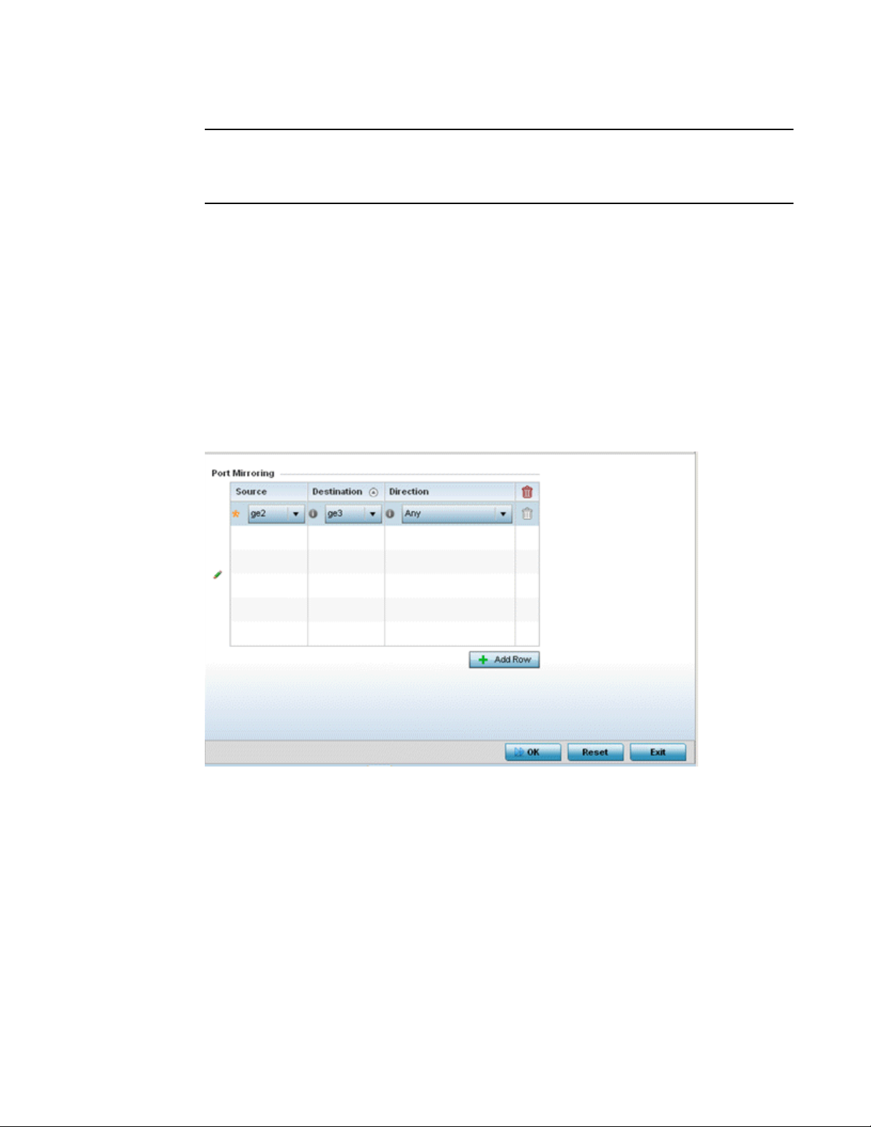
5
NOTE
Port mirroring is not supported on NX4500 or NX6500 models, as they only utilize GE ports 1 - 2.
Additionally, port mirroring is not supported on uplink (up) ports or wired ports on any controller or
service platform model.
To set a NX4524 or NX6524 service platform port mirror configuration:
1. Select the Configuration tab from the Web UI.
2. Select Devices from the Configuration tab.
The Device Configuration screen displays a list of managed devices or peer controllers, service
platforms or Access Points.
3. Select a target device (by double-clicking it) from amongst those displayed within the Device
Configuration screen.
Devices can also be selected directly from the Device Browser in the lower, left-hand, side of
the UI.
4. Select Mirroring from the Device menu options.
FIGURE 17 Port Mirroring screen
70 Brocade Mobility RFS Controller System Reference Guide
53-1003099-01
Page 83

5
5. Set the following Port Mirroring values to define the ports and directions data is spanned on
the NX4524 or NX6524 model service platform:
Source
Destination
Direction
Select the GE port (1 - 24) used as the data source to span packets to the selected destination port.
The packets spanned from the selected source to the destination depend on whether Inbound,
Outbound or Any is selected as the direction. A source port cannot be a destination port.
Select the GE port (1 - 24) used as the port destination to span packets from the selected source. The
destination port serves as a duplicate image of the source port and can be used to send packets to a
network diagnostic without disrupting the behavior on the original port. The destination port transmits
only mirrored traffic and does not forward received traffic. Additionally, address learning is disabled on
the destination port.
Define the direction data packets are spanned from the selected source to the defined destination.
Packets spanned from the source to the destination depend on whether Inbound (received packets
only), Outbound (transmitted packets only) or Any (packets in either direction) is selected.
6. Select + Add Row to add different sources, destinations and directions for additional GE port
spanning configurations.
7. S el e c t OK to save the changes made to the NX4524 or NX6524 port mirroring configuration.
Selecting Reset reverts the screen to its last saved configuration.
RF Domain Overrides
Use RF Domain Overrides to define configurations overriding the configuration set by the target
device’s original RF Domain assignment.
RF Domains allow administrators to assign configuration data to multiple devices deployed in a
common coverage area (floor, building or site). In such instances, there’s many configuration
attributes these devices share, since their general client support roles are quite similar. However,
device configurations may need periodic refinement from their original RF Domain administered
design.
A controller or service platform configuration contains (at a minimum) one default RF Domain, but
can optionally use additional user defined RF Domains:
• Default RF Domain - Automatically assigned to each controller, service platform and
associated Access Points by default. A default RF Domain is unique to a specific model.
• User Defined RF Domains - Created by administrators and manually assigned to individual
controllers, service platforms or Access Points, but can be automatically assigned to Access
Points using adoption policies.
Each controller, service platform and Access Point is assigned one RF Domain at a time. However, a
user defined RF Domain can be assigned to multiple devices as required. User defined RF Domains
can be manually assigned or automatically assigned to Access Points using an auto provisioning
policy. The more devices assigned a single RF Domain, the greater the likelihood one of the
device’s configurations will require an override deviating that device’s configuration from the
original RF Domain assignment shared by the others.
To review the RF Domain’s original configuration requirements and the options available for a
target device, refer to Managing RF Domains.
To define a device’s RF Domain override configuration:
1. Select the Configuration tab from the Web UI.
Brocade Mobility RFS Controller System Reference Guide 71
53-1003099-01
Page 84
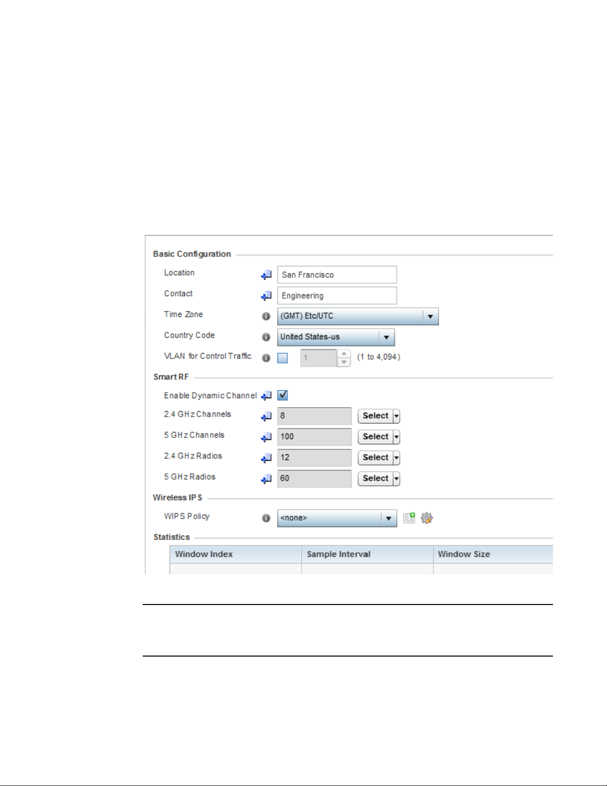
5
NOTE
2. Select Devices from the Configuration tab.
The Device Configuration screen displays a list of managed devices or peer controllers,
service platforms or Access Points.
3. Select a device (by double-clinking it) from amongst those displayed within the Device
Configuration screen.
Devices can also be selected directly from the Device Browser in the lower, left-hand, side of
the UI.
4. Expand the RF Domain Overrides menu option to display its sub-menu options.
5. Select RF Domain.
FIGURE 18 RF Domain Overrides screen
A blue override icon (to the left of a parameter) defines the parameter as having an override applied.
To remove an override go to the Basic Configuration section of the device and click the Clear
Overrides button. This removes all overrides from the device.
72 Brocade Mobility RFS Controller System Reference Guide
53-1003099-01
Page 85

5
6. Refer to the Basic Configuration field to review the basic settings defined for the target device’s
RF Domain configuration, and optionally assign/remove overrides to and from specific
parameters.
Location
Contact
Time Zone
Country Code
VLAN for Control Traffic
Provide the 64 character maximum deployment location set for the controller or
service platform as part of its RF Domain configuration.
Enter the 64 character maximum administrative contact for the controller or service
platform as part of its RF Domain configuration.
Displays the time zone utilized for the RF Domain configuration.
Displays the country code set for the as part of the RF Domain configuration.
Displays the VLAN for Control Traffic setting for the device as part of its RF Domain
configuration.
7. Ref e r to t he Smart RF section to configure Smart RF policy and dynamic channel settings.
2.4 GHz Radios
5 GHz Radios
Select an override group of channels Smart RF can use for channel compensation
adjustments in the 2.4 GHz band.
Select an override group of channels Smart RF can use for channel compensation
adjustments in the 5 GHz band.
8. Refer to the Smart Scan section to configure Smart RF policy and dynamic channel settings.
Enable Dynamic
Select this option to enable dynamic channel switching for Smart RF radios.
Channel
2.4 GHz Channels
5 GHz Channels
Select channels from the drop-down menu and click the down arrow to move it to
the list of channels used for 2.4GHz Smart RF radios.
Select channels from the drop-down menu and click the down arrow to move it to
the list of channels used for 5GHz Smart RF radios.
9. Select the Create icon to define a new Smart RF policy that can be applied to the RF Domain,
or select the Edit icon to modify or override an existing Smart RF policy.
For an overview of Smart RF and instructions on how to create a Smart RF policy that can be
used with a RF Domain, see Smart RF Policy.
10. Use the WIPS Policy drop-down menu to apply a WIPS policy to the RF Domain.
The Wireless Intrusion Protection System (WIPS) provides continuous protection against
wireless threats and act as an additional layer of security complementing wireless VPNs and
encryption and authentication policies. Controllers and service platforms support WIPS
through the use of dedicated sensor devices, designed to actively detect and locate
unauthorized AP devices. After detection, they use mitigation techniques to block devices using
manual termination, air lockdown or port suppression.
11. Select the Create icon to define a new WIPS policy that can be applied to the RF Domain, or
select the Edit icon to modify or override an existing WIPS policy.
For an overview of WIPS and instructions on how to create a WIPS policy that can be used with
a RF Domain, see Intrusion Prevention.
Brocade Mobility RFS Controller System Reference Guide 73
53-1003099-01
Page 86
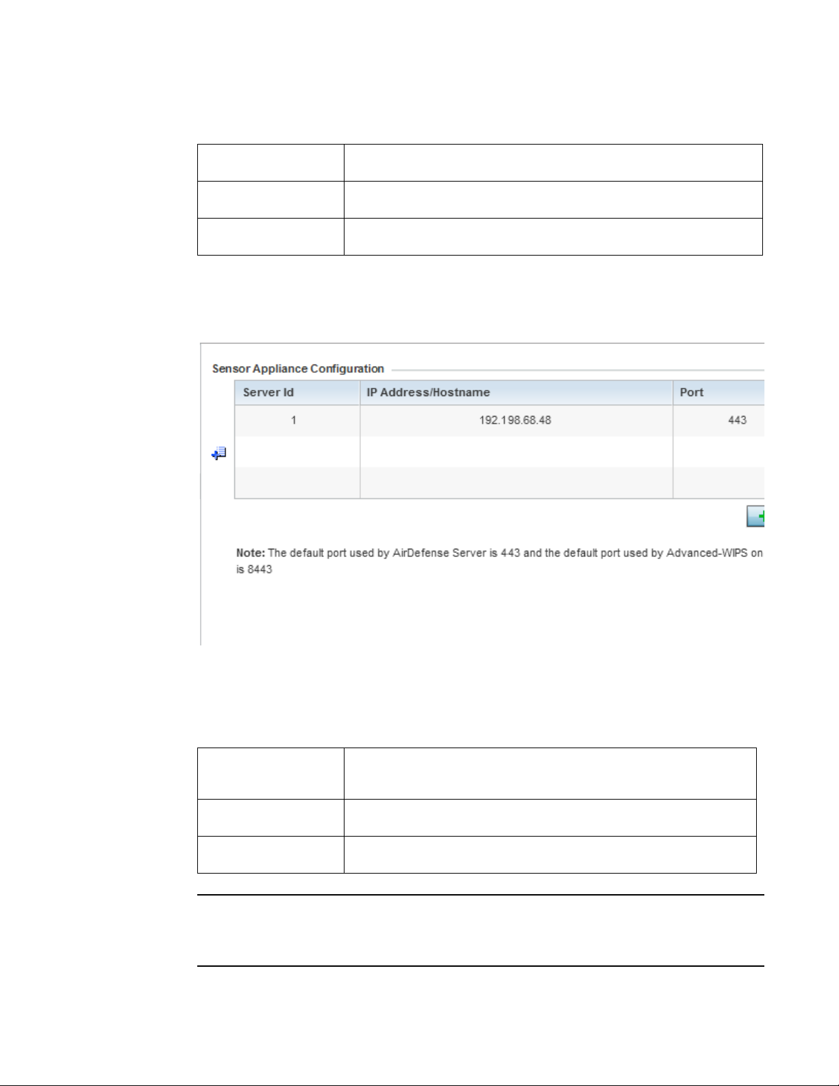
5
NOTE
12. Refer to the Statistics field to set the following data:
Window Index
Sample Interval
Window Size
Use the spinner control to set a numerical index used as an identifier for RF Domain
statistics.
Use the spinner control to define the interval (in seconds) to capture windowed
statistics supporting with the listed RF Domain. The default is 5 seconds.
Use the spinner control to set the number of samples used to define RF Domain
statistics. The default value is 6 samples.
13. Select OK to save the changes and overrides made to the RF Domain configuration. Selecting
Reset reverts the screen to its last saved configuration.
14. Select Sensor Configuration from within the expanded RF Domain Overrides menu.
FIGURE 19 Sensor Configuration Override screen
15. Define a Sensor Configuration for dedicating a WIPS server resource for client terminations
and WIPS event logging.
Optionally set up to 3 overrides for the listed device’s sensor server assignment:
Server Id
IP Address/Hostname
Port
Use the spinner control set a numerical index to differentiate this server from
other servers. Up to 3 sensor server resources can be defined. Select + Add Row
as needed to add additional servers.
Set IP Addresses or Hostnames of up to 3 sensor servers supporting WIPS events
on behalf of the controller or service platform.
Assign the sensor server port number using the spinner control. The default port is
443.
A blue override icon (to the left of a parameter) defines the parameter as having an override applied.
To remove an override go to the Basic Configuration section of the device and click the Clear
Overrides button. This removes all overrides from the device.
74 Brocade Mobility RFS Controller System Reference Guide
53-1003099-01
Page 87
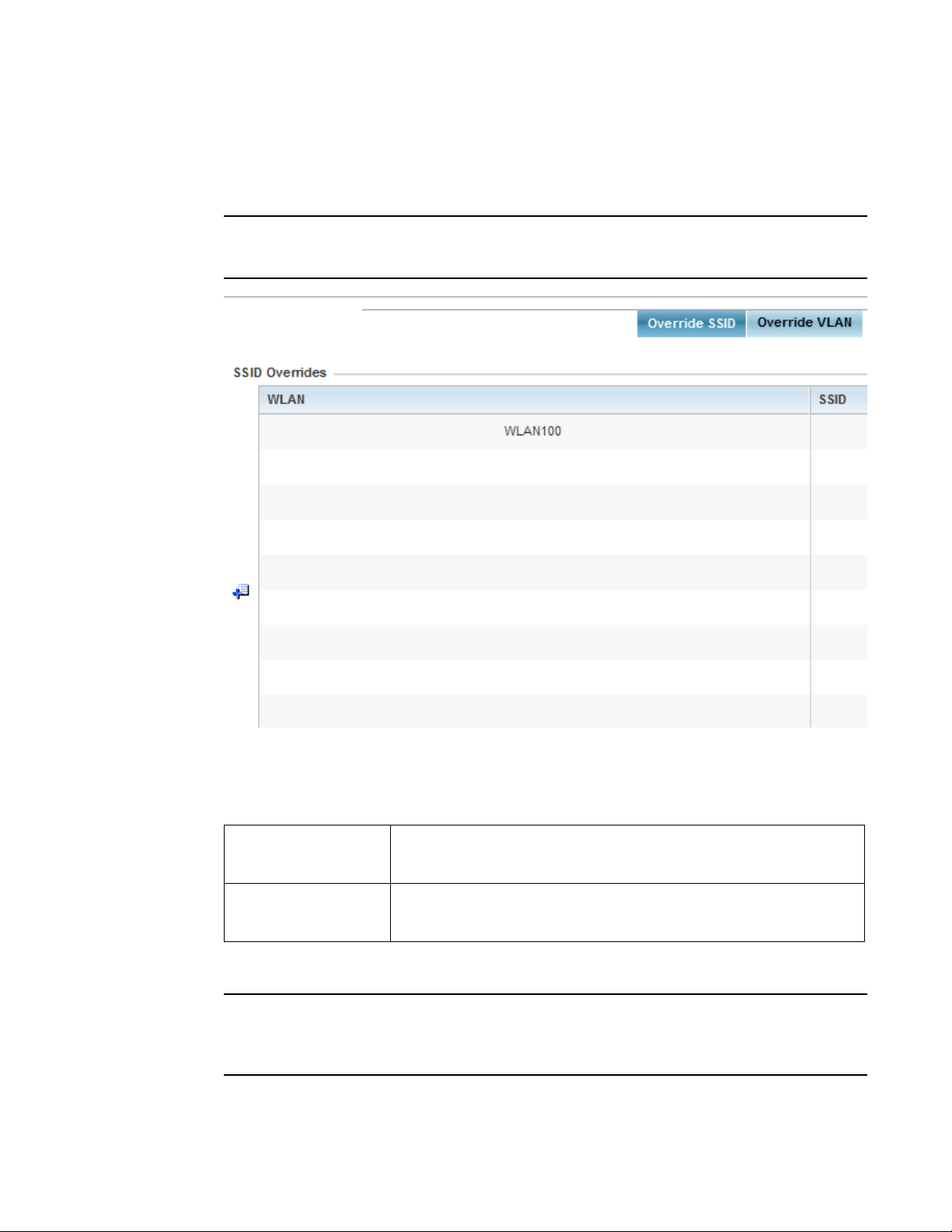
5
NOTE
NOTE
16. Select OK to save the changes and overrides made to the Sensor Appliance Configuration.
Selecting Reset reverts the screen to its last saved configuration.
17. Select WLAN Override from within the expanded RF Domain Overrides.
The WLAN Override option does not appear as a sub menu option under RF Domain Overrides for
either controllers or service platforms, just Access Points.
FIGURE 20 WLAN Override screen - Override SSID tab
The WLAN Override screen displays with the Override SSID tab displayed by default.
18. Optionally define up to 3 overrides for the listed Access Point’s WLAN SSID assignment:
WLAN
SSID
Optionally use the drop-down menu to change the WLAN assignment for the listed
Access Point. Select either the Create icon to define a new WLAN configuration, or
select the Edit icon to modify an existing WLAN configuration.
Optionally change the SSID associated with the WLAN. The WLAN name is
auto-generated using the SSID until changed (overridden). The maximum number
of characters used for the SSID is 32.
19. Select the Add Row + button as needed to add additional WLAN SSID overrides.
A blue override icon (to the left of a parameter) defines the parameter as having an override applied.
To remove an override go to the Basic Configuration section of the device and click the Clear
Overrides button. This removes all overrides from the device.
Brocade Mobility RFS Controller System Reference Guide 75
53-1003099-01
Page 88
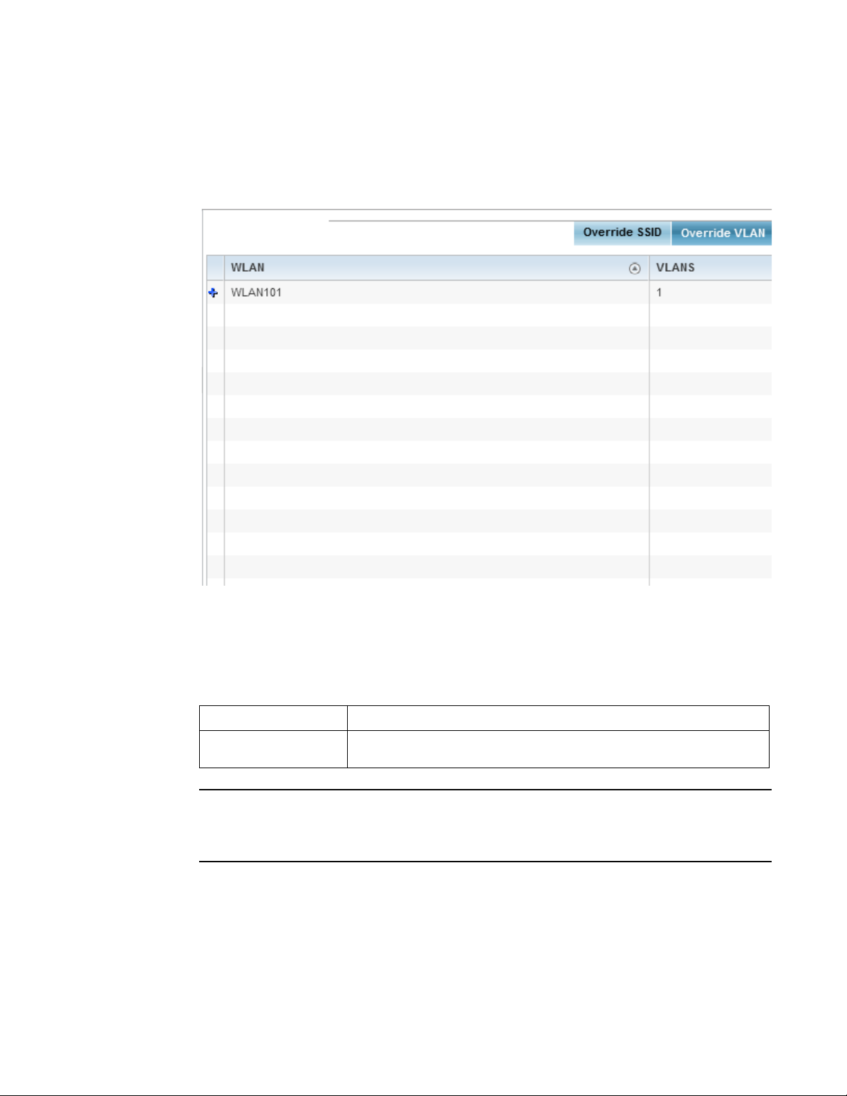
5
NOTE
20. Select OK to save the changes and overrides. Selecting Reset reverts the screen to its last
saved configuration.
21. Select the Override VLAN tab to review any VLAN assignment overrides that may have been or
optionally add or edit override configurations.
FIGURE 21 WLAN Override screen - Override VLAN tab
The Override VLANs tab displays the VLANs assigned to the WLAN on the Access Point. Select
Add to create a new client limit configuration for a specific WLAN and VLAN or Edit to modify an
existing configuration.
22. Optionally define a VLAN’s wireless client limit override configuration.
VLANS
Wireless Client Limit
A blue override icon (to the left of a parameter) defines the parameter as having an override applied.
To remove an override go to the Basic Configuration section of the device and click the Clear
Overrides button. This removes all overrides from the device.
23. Select OK to save the changes and overrides. Selecting Reset reverts the screen to its last
saved configuration.
Use the spinner control to set a virtual interface ID (between 1 - 4094).
Use the spinner control to set the number of users permitted on the VLAN. Set the
value to 0 to have an unlimited number of users.
76 Brocade Mobility RFS Controller System Reference Guide
53-1003099-01
Page 89
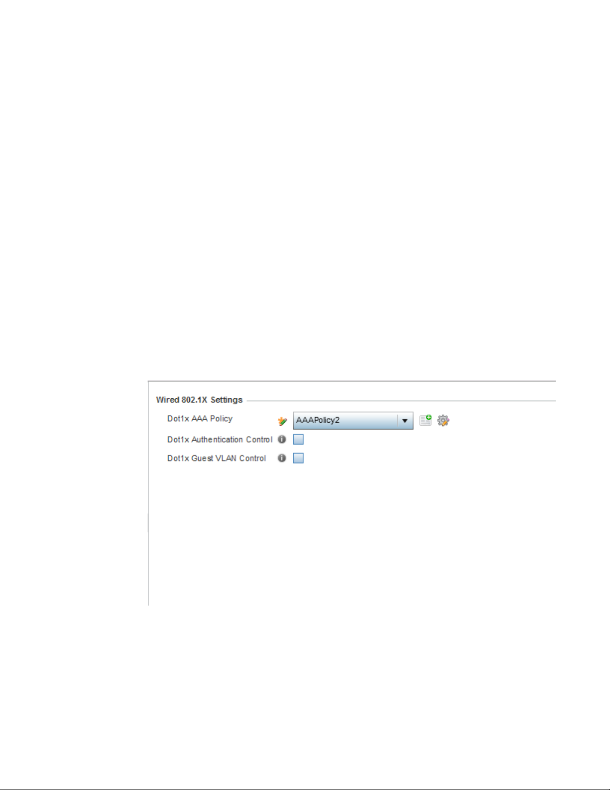
Wired 802.1x Configuration
802.1X is an IEEE standard for media-level (Layer 2) access control, providing the capability to
permit or deny connectivity based on user or device identity. 802.1X allows port based access
using authentication. An 802.1X enabled port can be dynamically enabled or disabled depending
on user identity or device connection.
Before authentication, the endpoint is unknown, and traffic is blocked. Upon authentication, the
endpoint is known and traffic is allowed. The controller or service platform uses source MAC
filtering to ensure only the authenticated endpoint is allowed to send traffic.
To configure a device’s wired 802.1x configuration:
1. Select the Configuration tab from the Web UI.
2. Select Devices from the Configuration tab.
The Device Configuration screen displays a list of managed devices or peer controllers, service
platforms or Access Points.
3. Select a device (by double-clicking it) from amongst those displayed within the Device
Configuration screen.
Devices can also be selected directly from the Device Browser in the lower, left-hand, side of
the UI.
5
4. Select Wired 802.1x from the Device menu options.
FIGURE 22 Device Wired 802.1x screen
Brocade Mobility RFS Controller System Reference Guide 77
53-1003099-01
Page 90

5
5. Review the Wired 802.1x Settings area to configure the following parameters.
Dot1x Authentication
Control
Dot1x AAA Policy
Dot1x Guest VLAN
Control
MAC Authentication
Control
Select this option to globally enable 802.1x authentication. 802.1x authentication is disabled by
default.
Use the drop-down menu to select a AAA policy to associate with wired 802.1x traffic. If a suitable AAA
policy does not exist, select the Create icon to create a new policy or the Edit icon to modify an existing
policy.
Select this option to globally enable the use of 802.1x guest VLANs.
Use the drop-down menu to select an AAA authentication policy for MAC address authentication. If a
suitable MAC AAA policy does not exist, click the Create icon to create a new policy or the Edit icon to
modify an existing policy.
Profile Overrides
Profiles enable administrators to assign a common set of parameters and policies to controllers,
service platforms and Access Points. Profiles can be used to assign shared or unique network,
wireless and security parameters to wireless controllers and Access Points across a large, multi
segment, site. The configuration parameters within a profile are based on the hardware model the
profile was created to support. Controllers and service platforms support both default and user
defined profiles implementing new features or updating existing parameters to groups of devices.
The central benefit of a profile is its ability to update devices collectively without having to modify
individual device configurations. Power and Adoption overrides apply specifically to Access Points,
while Cluster configuration overrides apply to only controller or service platform configurations.
However, device profile configurations may need periodic refinement from their original
administered design. Consequently, a device profile could require modification from a profile
configuration shared amongst numerous devices deployed within a particular site.
Use Profile Overrides to define configurations overriding the parameters set by the target device’s
original profile assignment.
To review a profile’s original configuration requirements and the options available for a target
device, refer to General Profile Configuration.
To define a device’s general profile override configuration:
1. Select the Configuration tab from the Web UI.
2. Select Devices from the Configuration tab.s
The Device Configuration screen displays a list of managed devices or peer controllers,
service platforms or Access Points.
3. Select a device (by double-clinking it) from amongst those displayed within the Device
Configuration screen.
Devices can also be selected directly from the Device Browser in the lower, left-hand, side
of the UI.
4. Select Profile Overrides from the Device menu to expand it into sub menu options.
5. Select General if it doesn’t display by default.
78 Brocade Mobility RFS Controller System Reference Guide
53-1003099-01
Page 91
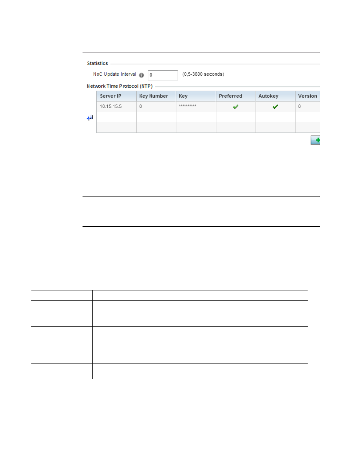
FIGURE 23 Profile Overrides - General screen
NOTE
5
Server IP
Key Number
Key
Preferred
AutoKey
Version
A blue override icon (to the left of a parameter) defines the parameter as having an override applied.
To remove an override go to the Basic Configuration section of the device and click the Clear
Overrides button. This removes all overrides from the device.
6. Select the IP Routing option (within the Settings field) to enable routing for the device.
7. Se t a NoC Update Interval of 0, or from 5-300 seconds for updates from the RF Domain
manager to the controller or service platform.
8. Select + Add Row below the Network Time Protocol (NTP) table to launch a screen used to
define (or override) the configurations of NTP server resources the controller or service
platform uses it obtain its system time. Set the following parameters to define the NTP
configuration:
Set the IP address of each server as a potential NTP resource.
Select the number of the associated Authentication Key for the NTP resource.
If an autokey is not being used, manually enter a 64 character maximum key the controller or service
platform and NTP resource share to securely interoperate.
Select the radio button to designate this particular NTP resource as preferred. If using multiple NTP
resources, preferred resources are given first opportunity to connect to the controller or service
platform and provide NTP calibration.
Select the radio button to enable an Autokey configuration for the controller or service platform and
NTP resource. The default setting is disabled.
Use the spinner control to specify the version number used by this NTP server resource. The default
setting is 0.
9. Refer to the RAID Alarm field to either enable or disable the chassis alarm that sounds when
events are detected that degrade RAID support (drive content mirroring) on a NX9000 series
service platform.
Brocade Mobility RFS Controller System Reference Guide 79
53-1003099-01
Page 92

5
NOTE
RAID controller drive arrays are available within NX9000 series service platforms (RFS9510 models)
only. However, they can be administrated on behalf of a NX9000 profile by a different model service
platform or controller.
NX9000 series service platforms include a single Intel MegaRAID controller (virtual drive)
with RAID-1 mirroring support enabled. The online virtual drive supports up to two physical
drives that could require hot spare substitution if a drive were to fail. With the Mobility 5.5
release, an administrator can manage the RADI controller event alarm and syslogs
supporting the array hardware from the service platform user interface and is not required
to reboot the service platform BIOS.
For information on setting the service platform drive array configuration and diagnostic behavior of
its member drives, refer to RAID Operations on page 14-12. To view the service platform’s current
RAID array status, drive utilization and consistency check information, refer to RAID Statistics.
Select OK to save the changes and overrides made to the general profile configuration. Select
Reset to revert to the last saved configuration.
Cluster Configuration Overrides (Controllers and Service Platforms Only)
A redundancy group (cluster) is a set of controllers or service platforms (nodes) uniquely defined by
a profile configuration. Within the redundancy group, members discover and establish connections
to other peers and provide wireless self-healing support in the event of cluster member failure.
A cluster’s AP load balance is typically distributed evenly amongst the controllers or service
platforms in the cluster. Define how often this profile is load balanced for AP radio distribution as
often as you feel required, as radios can come and go and members can join and exit the cluster.
For information on setting a profile’s original cluster configuration (before applying an override),
see Profile Cluster Configuration (Controllers and Service Platforms Only).
As cluster memberships increase or decrease and their load requirements change, a profile may
need an override applied to best suit a site’s cluster requirements.
To apply an override (if required) to a profile cluster configuration:
1. Select the Configuration tab from the Web UI.
2. Select Devices from the Configuration tab.
The Device Configuration screen displays a list of devices or peer controllers service platforms
or Access Points.
3. Select a target device (by double-clinking it) from amongst those displayed within the Device
Configuration screen.
Devices can also be selected directly from the Device Browser in the lower, left-hand, side of
the UI.
4. Select Profile Overrides from the Device menu to expand it into sub menu options.
5. Select Cluster.
80 Brocade Mobility RFS Controller System Reference Guide
53-1003099-01
Page 93

5
NOTE
A blue override icon (to the left of a parameter) defines the parameter as having an override applied.
To remove an override go to the Basic Configuration section of the device and click the Clear
Overrides button. This removes all overrides from the device.
FIGURE 24 Profile Overrides - Cluster screen
Brocade Mobility RFS Controller System Reference Guide 81
53-1003099-01
Page 94

5
6. Optionally define the following Cluster Settings and overrides:
Cluster Mode
Cluster Name
Master Priority
Handle STP Convergence
Force Configured State
Force Configured State
Delay
A member can be in either an Active or Standby mode. All active member
controllers or service platforms can adopt Access Points. Standby members only
adopt Access Points when an active member has failed or sees an Access Point
that’s not yet adopted. The default cluster mode is Active and enabled for use
with the profile.
Define a name for the cluster name unique to its configuration or profile support
requirements. The name cannot exceed 64 characters.
Set a priority value from 1 and 255 with the higher value being given higher
priority. This configuration is the device’s priority to become cluster master. In
cluster environment one device from cluster members is elected as cluster
master. This configuration is the device’s priority to become cluster master. The
default value is 128.
Select the radio button to enable Spanning Tree Protocol (STP) convergence for
the controller or service platform. In general, this protocol is enabled in layer 2
networks to prevent network looping. Spanning Tree is a network layer protocol
that ensures a loop-free topology in a mesh network of inter-connected layer 2
controller or service platform. The spanning tree protocol disables redundant
connections and uses the least costly path to maintain a connection between
any two controllers or service platforms in the network. If enabled, the network
forwards data only after STP convergence. Enabling STP convergence delays the
redundancy state machine execution until the STP convergence is completed
(the standard protocol value for STP convergence is 50 seconds). Delaying the
state machine is important to load balance APs at startup. The default setting is
disabled.
Select the radio button to allow this controller or service platform to take over for
an active member if it were to fail. A standby controller or service platform in the
cluster takes over APs adopted by the failed active member. If the failed active
member were to come back up, the active member starts a timer based on the
Auto Revert Delay interval. At the expiration of the Auto Revert Delay, the standby
member releases all adopted APs and goes back to a monitoring mode. The Auto
Revert Delay timer is stopped and restarted if the active member goes down and
comes up during the Auto Revert Delay interval. The default value is disabled.
Specify a delay interval in minutes (1 - 1,800). This is the interval a standby
member waits before releasing adopted APs and goes back to a monitoring
mode when an active cluster member becomes active again after a failure. The
default interval is 5 minutes.
7. Wi t h i n th e Cluster Member field, select Cluster VLAN to enable a spinner control to designate
the VLAN where cluster members are reachable. Specify a VLAN from 1 - 4094.
Specify the IP addresses of the VLAN’s cluster members using the IP Address table.
8. Select OK to save the changes and overrides made to the profile’s cluster configuration. Select
Reset to revert to the last saved configuration.
Access Point Radio Power Overrides (Access Points Only)
A profile can manage the transmit output power of the Access Point radios it supports within the
network.
82 Brocade Mobility RFS Controller System Reference Guide
53-1003099-01
Page 95

5
NOTE
NOTE
The Power option only appears within the Profile Overrides menu tree if an Access Point is selected
from within the main Devices screen. Power management is configured differently for controllers or
service platforms, so the Power screen only displays for Access Points.
Use the Power screen to set or override one of two power modes (3af or Auto) for a managed
Access Point. When automatic is selected, the Access Point safely operates within available power.
Once the power configuration is determined, the Access Point configures its operating power
characteristics based on its model and power configuration.
An Access Point uses a complex programmable logic device (CPLD). The CPLD determines proper
supply sequencing, the maximum power available and other status information. One of the primary
functions of the CPLD is to determine the Access Point’s maximum power budget. When an Access
Point is powered on (or performing a cold reset), the CPLD determines the maximum power
provided by the POE device and the budget available to the Access Point. The CPLD also
determines the access point hardware SKU and the number of radios. If the Access Point’s POE
resource cannot provide sufficient power (with all intended interfaces enabled), some of the
following interfaces could be disabled or modified:
• The Access Point’s transmit and receive algorithms could be negatively impacted
• The Access Point’s transmit power could be reduced due to insufficient power
• The Access Point’s WAN port configuration could be changed (either enabled or disabled)
To define an Access Point’s power configuration or apply an override to an existing parameter:
1. Select the Devices tab from the Web UI.
2. Select Profile Overrides to expand its sub menu items.
3. Select Power.
A screen displays where an Access Point’s power configuration can be defined or
overridden for a profile.
A blue override icon (to the left of a parameter) defines the parameter as having an override applied.
To remove an override go to the Basic Configuration section of the device and click the Clear
Overrides button. This removes all overrides from the device.
Brocade Mobility RFS Controller System Reference Guide 83
53-1003099-01
Page 96
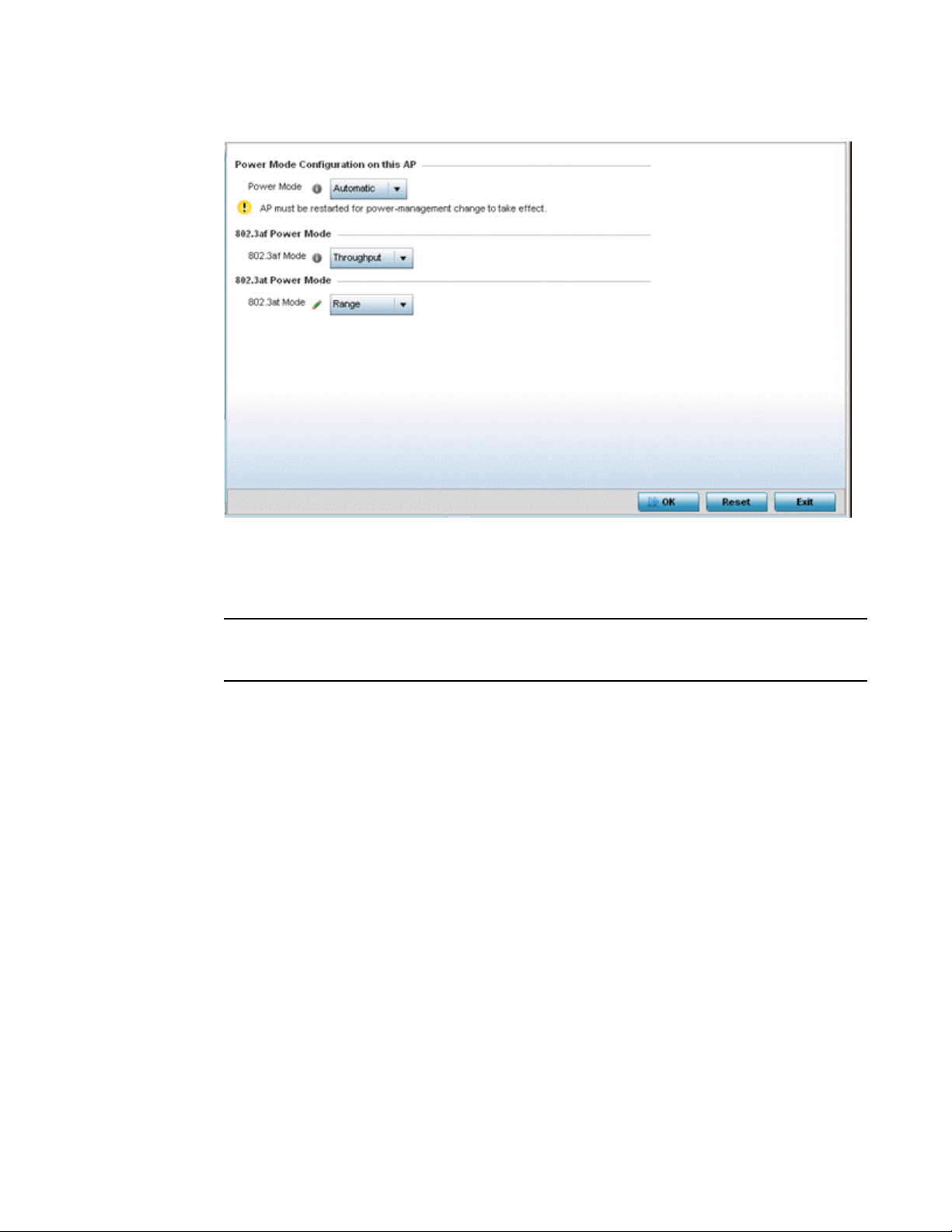
5
NOTE
FIGURE 25 Access Point Profile Power Override screen
4. Use the Power Mode drop-down menu to set or override the Power Mode Configuration on this
AP.
Single radio model Access Point’s always operate using a full power configuration. The power
management configurations described in this section do not apply to single radio models.
When an Access Point is powered on for the first time, the system determines the power
budget available to the Access Point. Using the Automatic setting, the Access Point
automatically determines the best power configuration based on the available power budget.
Automatic is the default setting.
If 802.3af is selected, the Access Point assumes 12.95 watts are available. If the mode is
changed, the Access Point requires a reset to implement the change. If 802.3at is selected,
the Access Point assumes 23 - 26 watts are available.
5. Set or override the Access Point radio’s 802.3af Power Mode and the radio’s 802.3at Power
Mode.
Use the drop-down menu to define a mode of either Range or Throughput.
Select Throughput to transmit packets at the radio’s highest defined basic rate (based on the
radio’s current basic rate settings). This option is optimal in environments where the
transmission range is secondary to broadcast/multicast transmission performance. Select
Range when range is preferred over performance for broadcast/multicast (group) traffic. The
data rates used for range are the lowest defined basic rates. Throughput is the default setting
for both 802.3af and 802.3at.
6. Select OK to save the changes and overrides made to the Access Point power configuration.
Select Reset to revert to the last saved configuration.
84 Brocade Mobility RFS Controller System Reference Guide
53-1003099-01
Page 97

5
NOTE
NOTE
Access Point Adoption Overrides (Access Points Only)
Adoption is the process an Access Point uses to discover available controllers or service platforms,
pick the most desirable one, establish an association and optionally obtain an image upgrade and
configuration. Adoption is configurable and supported within a device profile and applied to other
Access Points supported by the profile. Individual attributes of an Access Point’s auto provisioning
policy can be overridden as specific parameters require modification.
At adoption, an Access Point solicits and receives multiple adoption responses from controllers and
service platforms available on the network. These adoption responses contain loading policy
information the Access Point uses to select the optimum controller or service platform for adoption.
By default, an auto provisioning policy generally distributes AP adoption evenly amongst available
controllers and service platforms. Modify existing adoption policies or create a new one as needed
to meet the adoption requirements of a device and their assigned profile.
A device configuration does not need to be present for an auto provisioning policy to take effect.
Once adopted, and the device’s configuration is defined and applied by the controller or service
platform, the auto provisioning policy mapping does not have impact on subsequent adoptions by
the same device.
An auto provisioning policy enables an administrator to define adoption rules for the supported
Access Points capable of being adopted by a wireless controller.
To define an Access Point’s adoption configuration or apply an override:
1. Select the Devices from the Web UI.
2. Select Profiles from the Configuration tab.
3. Select Profile Overrides to expand its sub-menu items.
4. Select Adoption.
A screen displays where an Access Point’s adoption configuration can be defined and
overridden for a profile.
A blue override icon (to the left of a parameter) defines the parameter as having an override applied.
To remove an override go to the Basic Configuration section of the device and click the Clear
Overrides button. This removes all overrides from the device.
Brocade Mobility RFS Controller System Reference Guide 85
53-1003099-01
Page 98
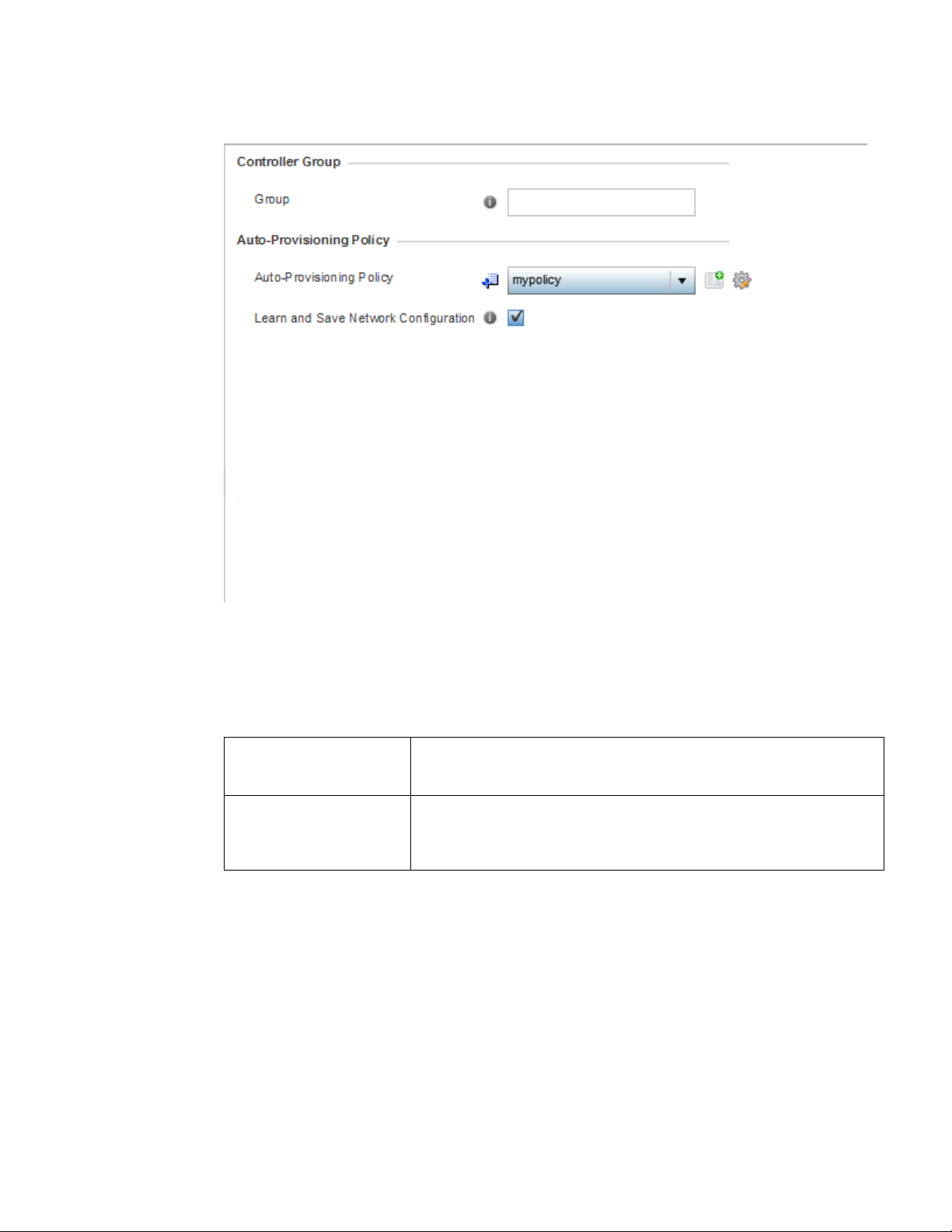
5
FIGURE 26 Access Point Adoption Override screen
5. Define or override the Preferred Group used as optimal group for the Access Point’s adoption.
The name of the preferred group cannot exceed 64 characters.
6. Set the following Controller Hello Interval settings manage message exchanges and
connection re-establishments between adopting devices:
Hello Interval
Adjacency Hold Time
Define an interval (from 1 - 120 seconds) between hello keep alive messages
exchanged with the adopting device. These messages serve as a connection
validation mechanism to ensure the availability of the adopting resource.
Set the time (from 2 - 600 seconds) after the last hello packet after which the
connection between the controller and Access Point is defined as lost and their
connection is re-established. When a hello interval is set, an adjacency hold time is
mandatory and should be higher then the hello interval.
7. Select the check box to define or override a VLAN the Access Point’s associating controller or
service platform is reachable on.
VLANs 0 and 4,094 are reserved and cannot be used by a controller or service platform
VLAN.
8. Enter Controller Hostnames as needed to define or override resources for Access Point
adoption.
86 Brocade Mobility RFS Controller System Reference Guide
53-1003099-01
Page 99

5
NOTE
Select + Add Row as needed to populate the table with IP Addresses or Hostnames used
as Access Point adoption resources into the managed network.
Host
Pool
Routing Level
IPSec Secure
IPSec GW
Force
Remote VPN Client
Use the drop-down menu to specify whether the adoption resource is defined as
a (non DNS) IP Address or a Hostname. Once defined, provide the numerical IP
or Hostname. A Hostname cannot exceed 64 characters.
Use the spinner control to set a pool of either 1 or 2. This is the pool the target
controller or service platform belongs to.
Define a routing level (either 1 or 2) for the link between adopting devices. The
default setting is 1.
Enable this option to provide IPSec secure peer authentication on the
connection (link) between the adopting devices. This option is disabled by
default.
Select the numerical IP address or administrator defined hostname of the
adopting controller resource.
Enable this setting to create a forced link between an Access Point and adopting
controller, even when not necessarily needed. This setting is disabled by default.
Displays whether a secure controller link has been established using a remote
VPN client.
9. Select OK to save the changes and overrides made to the Access Point profile adoption
configuration. Select Reset to revert to the last saved configuration.
Adoption Overrides (Controllers Only)
Adoption is the process an Access Point uses to discover available controllers, pick the most
desirable controller, establish a controller association and optionally obtain an image upgrade and
configuration. Adoption is configurable and supported within a device profile and applied to other
Access Points supported by the profile. Individual attributes of an Access Point’s auto provisioning
policy can be overridden as specific parameters require modification.
At adoption, an Access Point solicits and receives multiple adoption responses from controllers and
service platforms available on the network. These adoption responses contain loading policy
information the Access Point uses to select the optimum controller or service platform for adoption.
By default, an auto provisioning policy generally distributes AP adoption evenly amongst available
controllers and service platforms. Modify existing adoption policies or create a new one as needed
to meet the adoption requirements of a device and their assigned profile.
A device configuration does not need to be present for an auto provisioning policy to take effect.
Once adopted, and the device’s configuration is defined and applied by the controller or service
platform, the auto provisioning policy mapping does not have impact on subsequent adoptions by
the same device.
To define a controller or service platform’s adoption configuration:
1. Select the Devices from the Web UI.
2. Select Profiles.
3. Select Profile Overrides to expand its sub-menu items.
4. Select Adoption.
Brocade Mobility RFS Controller System Reference Guide 87
53-1003099-01
Page 100
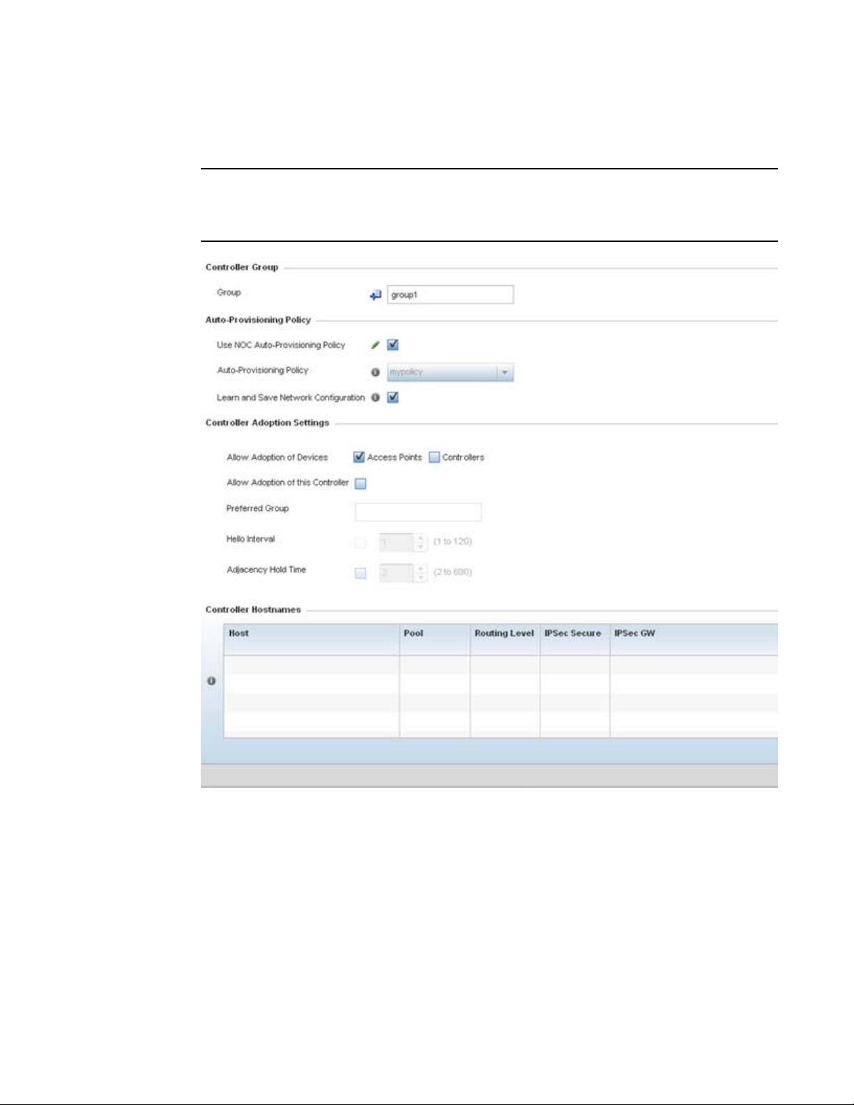
5
NOTE
A screen displays where a controller or service platform’s adoption configuration can be
set or overridden for a profile.
A blue override icon (to the left of a parameter) defines the parameter as having an override applied.
To remove an override go to the Basic Configuration section of the device and click the Clear
Overrides button. This removes all overrides from the device.
FIGURE 27 Controller Adoption Override screen
5. Within the Controller Group field, use the Group item to set provide the controller group this
controller or service platform belongs to. A preferred group can also be selected for the
adoption of this controller or service platform. The name of the preferred group cannot exceed
64 characters.
88 Brocade Mobility RFS Controller System Reference Guide
53-1003099-01
 Loading...