

Page 1

53-1003098-01
®
20 January 2014
Brocade Mobility RFS
Controller
CLI Reference Guide
Supporting software release 5.5.0.0 and later
Page 2

Copyright © 2014 Brocade Communications Systems, Inc. All Rights Reserved.
ADX, AnyIO, Brocade, Brocade Assurance, the B-Mobility symbol, DCX, Fabric OS, ICX, MLX, MyBrocade, OpenScript, VCS, VDX,
and Vyatta are registered trademarks, and HyperEdge, The Effortless Network, and The On-Demand Data Center are trademarks
of Brocade Communications Systems, Inc., in the United States and/or in other countries. Other brands, products, or service
names mentioned may be trademarks of their respective owners.
Notice: This document is for informational purposes only and does not set forth any warranty, expressed or implied, concerning
any equipment, equipment feature, or service offered or to be offered by Brocade. Brocade reserves the right to make changes to
this document at any time, without notice, and assumes no responsibility for its use. This informational document describes
features that may not be currently available. Contact a Brocade sales office for information on feature and product availability.
Export of technical data contained in this document may require an export license from the United States government.
The authors and Brocade Communications Systems, Inc. shall have no liability or responsibility to any person or entity with
respect to any loss, cost, liability, or damages arising from the information contained in this book or the computer programs that
accompany it.
The product described by this document may contain “open source” software covered by the GNU General Public License or other
open source license agreements. To find out which open source software is included in Brocade products, view the licensing
terms applicable to the open source software, and obtain a copy of the programming source code, please visit
http://www.brocade.com/support/oscd.
Brocade Communications Systems, Incorporated
Corporate and Latin American Headquarters
Brocade Communications Systems, Inc.
130 Holger Way
San Jose, CA 95134
Tel: 1-408-333-8000
Fax: 1-408-333-8101
E-mail: info@brocade.com
European Headquarters
Brocade Communications Switzerland Sàrl
Centre Swissair
Tour B - 4ème étage
29, Route de l'Aéroport
Case Postale 105
CH-1215 Genève 15
Switzerland
Tel: +41 22 799 5640
Fax: +41 22 799 5641
E-mail: emea-info@brocade.com
Asia-Pacific Headquarters
Brocade Communications Systems China HK, Ltd.
No. 1 Guanghua Road
Chao Yang District
Units 2718 and 2818
Beijing 100020, China
Tel: +8610 6588 8888
Fax: +8610 6588 9999
E-mail: china-info@brocade.com
Asia-Pacific Headquarters
Brocade Communications Systems Co., Ltd. (Shenzhen WFOE)
Citic Plaza
No. 233 Tian He Road North
Unit 1308 – 13th Floor
Guangzhou, China
Tel: +8620 3891 2000
Fax: +8620 3891 2111
E-mail: china-info@brocade.com
Document History
Title Publication number Summary of changes Date
Brocade Mobility RFS Controller CLI
Reference Guide
53-1003098-01 New Additions for software
version 5.5.0.0
January 2014
Page 3

Contents
About This Guide
Supported hardware and software . . . . . . . . . . . . . . . . . . . . . . . . . . xix
Document Conventions . . . . . . . . . . . . . . . . . . . . . . . . . . . . . . . . . . . xix
Text formatting x i x
Notes xx
Understanding command syntax xx
Related publications . . . . . . . . . . . . . . . . . . . . . . . . . . . . . . . . . . . . . . xxi
Getting technical help. . . . . . . . . . . . . . . . . . . . . . . . . . . . . . . . . . . . .xxii
Chapter 1 INTRODUCTION
CLI Overview . . . . . . . . . . . . . . . . . . . . . . . . . . . . . . . . . . . . . . . . . . . . . 2
Getting Context Sensitive Help . . . . . . . . . . . . . . . . . . . . . . . . . . . . . . . 5
Using the No Command . . . . . . . . . . . . . . . . . . . . . . . . . . . . . . . . . . . . 7
Basic Conventions . . . . . . . . . . . . . . . . . . . . . . . . . . . . . . . . . . . . . 7
Using CLI Editing Features and Shortcuts. . . . . . . . . . . . . . . . . . . . . . 7
Moving the Cursor on the Command Line . . . . . . . . . . . . . . . . . . 7
Completing a Partial Command Name. . . . . . . . . . . . . . . . . . . . . 8
Command Output pagination . . . . . . . . . . . . . . . . . . . . . . . . . . . . 9
Creating Profiles. . . . . . . . . . . . . . . . . . . . . . . . . . . . . . . . . . . . . . . 9
Change the default profile by creating vlan 150 and
mapping to ge3 Physical interface . . . . . . . . . . . . . . . . . . . . . . . 10
Remote Administration . . . . . . . . . . . . . . . . . . . . . . . . . . . . . . . . 11
Chapter 2 USER EXEC MODE COMMANDS
User Exec Commands. . . . . . . . . . . . . . . . . . . . . . . . . . . . . . . . . . . . . 16
captive-portal-page-upload . . . . . . . . . . . . . . . . . . . . . . . . . . . . . 17
change-passwd . . . . . . . . . . . . . . . . . . . . . . . . . . . . . . . . . . . . . . 19
clear . . . . . . . . . . . . . . . . . . . . . . . . . . . . . . . . . . . . . . . . . . . . . . . 19
clock . . . . . . . . . . . . . . . . . . . . . . . . . . . . . . . . . . . . . . . . . . . . . . .26
cluster . . . . . . . . . . . . . . . . . . . . . . . . . . . . . . . . . . . . . . . . . . . . . . 27
connect . . . . . . . . . . . . . . . . . . . . . . . . . . . . . . . . . . . . . . . . . . . . .28
create-cluster . . . . . . . . . . . . . . . . . . . . . . . . . . . . . . . . . . . . . . . .29
crypto . . . . . . . . . . . . . . . . . . . . . . . . . . . . . . . . . . . . . . . . . . . . . . 30
device-upgrade. . . . . . . . . . . . . . . . . . . . . . . . . . . . . . . . . . . . . . .39
disable . . . . . . . . . . . . . . . . . . . . . . . . . . . . . . . . . . . . . . . . . . . . .49
enable. . . . . . . . . . . . . . . . . . . . . . . . . . . . . . . . . . . . . . . . . . . . . .50
join-cluster . . . . . . . . . . . . . . . . . . . . . . . . . . . . . . . . . . . . . . . . . .50
l2tpv3 . . . . . . . . . . . . . . . . . . . . . . . . . . . . . . . . . . . . . . . . . . . . . . 51
logging . . . . . . . . . . . . . . . . . . . . . . . . . . . . . . . . . . . . . . . . . . . . . 53
mint. . . . . . . . . . . . . . . . . . . . . . . . . . . . . . . . . . . . . . . . . . . . . . . .54
no . . . . . . . . . . . . . . . . . . . . . . . . . . . . . . . . . . . . . . . . . . . . . . . . .55
Brocade Mobility RFS Controller CLI Reference Guide iii
53-1003098-01
Page 4

page . . . . . . . . . . . . . . . . . . . . . . . . . . . . . . . . . . . . . . . . . . . . . . . 59
ping . . . . . . . . . . . . . . . . . . . . . . . . . . . . . . . . . . . . . . . . . . . . . . . .59
ssh. . . . . . . . . . . . . . . . . . . . . . . . . . . . . . . . . . . . . . . . . . . . . . . . . 60
telnet. . . . . . . . . . . . . . . . . . . . . . . . . . . . . . . . . . . . . . . . . . . . . . .61
terminal . . . . . . . . . . . . . . . . . . . . . . . . . . . . . . . . . . . . . . . . . . . . 62
time-it . . . . . . . . . . . . . . . . . . . . . . . . . . . . . . . . . . . . . . . . . . . . . . 62
traceroute. . . . . . . . . . . . . . . . . . . . . . . . . . . . . . . . . . . . . . . . . . .63
watch . . . . . . . . . . . . . . . . . . . . . . . . . . . . . . . . . . . . . . . . . . . . . .64
exit. . . . . . . . . . . . . . . . . . . . . . . . . . . . . . . . . . . . . . . . . . . . . . . . . 65
virtual-machine . . . . . . . . . . . . . . . . . . . . . . . . . . . . . . . . . . . . . . 65
Chapter 3 PRIVILEGED EXEC MODE COMMANDS
Privileged Exec Mode Commands . . . . . . . . . . . . . . . . . . . . . . . . . . . 76
archive . . . . . . . . . . . . . . . . . . . . . . . . . . . . . . . . . . . . . . . . . . . . .78
boot. . . . . . . . . . . . . . . . . . . . . . . . . . . . . . . . . . . . . . . . . . . . . . . .80
captive-portal-page-upload . . . . . . . . . . . . . . . . . . . . . . . . . . . . . 81
cd . . . . . . . . . . . . . . . . . . . . . . . . . . . . . . . . . . . . . . . . . . . . . . . . .83
change-passwd . . . . . . . . . . . . . . . . . . . . . . . . . . . . . . . . . . . . . . 83
clear . . . . . . . . . . . . . . . . . . . . . . . . . . . . . . . . . . . . . . . . . . . . . . . 84
clock . . . . . . . . . . . . . . . . . . . . . . . . . . . . . . . . . . . . . . . . . . . . . . .93
cluster . . . . . . . . . . . . . . . . . . . . . . . . . . . . . . . . . . . . . . . . . . . . . .93
configure. . . . . . . . . . . . . . . . . . . . . . . . . . . . . . . . . . . . . . . . . . . .94
connect . . . . . . . . . . . . . . . . . . . . . . . . . . . . . . . . . . . . . . . . . . . . .95
copy. . . . . . . . . . . . . . . . . . . . . . . . . . . . . . . . . . . . . . . . . . . . . . . .95
create-cluster . . . . . . . . . . . . . . . . . . . . . . . . . . . . . . . . . . . . . . . .96
crypto . . . . . . . . . . . . . . . . . . . . . . . . . . . . . . . . . . . . . . . . . . . . . . 97
delete . . . . . . . . . . . . . . . . . . . . . . . . . . . . . . . . . . . . . . . . . . . . .107
device-upgrade. . . . . . . . . . . . . . . . . . . . . . . . . . . . . . . . . . . . . .108
diff. . . . . . . . . . . . . . . . . . . . . . . . . . . . . . . . . . . . . . . . . . . . . . . .115
dir . . . . . . . . . . . . . . . . . . . . . . . . . . . . . . . . . . . . . . . . . . . . . . . .116
disable . . . . . . . . . . . . . . . . . . . . . . . . . . . . . . . . . . . . . . . . . . . .117
edit . . . . . . . . . . . . . . . . . . . . . . . . . . . . . . . . . . . . . . . . . . . . . . .118
enable. . . . . . . . . . . . . . . . . . . . . . . . . . . . . . . . . . . . . . . . . . . . .119
erase . . . . . . . . . . . . . . . . . . . . . . . . . . . . . . . . . . . . . . . . . . . . . .119
halt . . . . . . . . . . . . . . . . . . . . . . . . . . . . . . . . . . . . . . . . . . . . . . .120
join-cluster . . . . . . . . . . . . . . . . . . . . . . . . . . . . . . . . . . . . . . . . .121
l2tpv3 . . . . . . . . . . . . . . . . . . . . . . . . . . . . . . . . . . . . . . . . . . . . .122
logging . . . . . . . . . . . . . . . . . . . . . . . . . . . . . . . . . . . . . . . . . . . .123
mint. . . . . . . . . . . . . . . . . . . . . . . . . . . . . . . . . . . . . . . . . . . . . . .124
mkdir. . . . . . . . . . . . . . . . . . . . . . . . . . . . . . . . . . . . . . . . . . . . . .126
more . . . . . . . . . . . . . . . . . . . . . . . . . . . . . . . . . . . . . . . . . . . . . .127
no . . . . . . . . . . . . . . . . . . . . . . . . . . . . . . . . . . . . . . . . . . . . . . . .127
page . . . . . . . . . . . . . . . . . . . . . . . . . . . . . . . . . . . . . . . . . . . . . . 131
ping . . . . . . . . . . . . . . . . . . . . . . . . . . . . . . . . . . . . . . . . . . . . . . .132
pwd . . . . . . . . . . . . . . . . . . . . . . . . . . . . . . . . . . . . . . . . . . . . . . .133
re-elect . . . . . . . . . . . . . . . . . . . . . . . . . . . . . . . . . . . . . . . . . . . .134
reload . . . . . . . . . . . . . . . . . . . . . . . . . . . . . . . . . . . . . . . . . . . . .134
rename . . . . . . . . . . . . . . . . . . . . . . . . . . . . . . . . . . . . . . . . . . . .135
rmdir . . . . . . . . . . . . . . . . . . . . . . . . . . . . . . . . . . . . . . . . . . . . . .137
self . . . . . . . . . . . . . . . . . . . . . . . . . . . . . . . . . . . . . . . . . . . . . . .138
ssh. . . . . . . . . . . . . . . . . . . . . . . . . . . . . . . . . . . . . . . . . . . . . . . .138
telnet. . . . . . . . . . . . . . . . . . . . . . . . . . . . . . . . . . . . . . . . . . . . . .139
iv Brocade Mobility RFS Controller CLI Reference Guide
53-1003098-01
Page 5

terminal . . . . . . . . . . . . . . . . . . . . . . . . . . . . . . . . . . . . . . . . . . .140
time-it . . . . . . . . . . . . . . . . . . . . . . . . . . . . . . . . . . . . . . . . . . . . .140
traceroute. . . . . . . . . . . . . . . . . . . . . . . . . . . . . . . . . . . . . . . . . .141
upgrade . . . . . . . . . . . . . . . . . . . . . . . . . . . . . . . . . . . . . . . . . . . 141
upgrade-abort . . . . . . . . . . . . . . . . . . . . . . . . . . . . . . . . . . . . . .142
watch . . . . . . . . . . . . . . . . . . . . . . . . . . . . . . . . . . . . . . . . . . . . .143
exit. . . . . . . . . . . . . . . . . . . . . . . . . . . . . . . . . . . . . . . . . . . . . . . .144
virtual-machine . . . . . . . . . . . . . . . . . . . . . . . . . . . . . . . . . . . . .144
raid . . . . . . . . . . . . . . . . . . . . . . . . . . . . . . . . . . . . . . . . . . . . . . .152
Chapter 4 GLOBAL CONFIGURATION COMMANDS
Global Configuration Commands. . . . . . . . . . . . . . . . . . . . . . . . . . .157
aaa-policy . . . . . . . . . . . . . . . . . . . . . . . . . . . . . . . . . . . . . . . . . .158
aaa-tacacs-policy . . . . . . . . . . . . . . . . . . . . . . . . . . . . . . . . . . . .160
advanced-wips-policy. . . . . . . . . . . . . . . . . . . . . . . . . . . . . . . . .161
alias. . . . . . . . . . . . . . . . . . . . . . . . . . . . . . . . . . . . . . . . . . . . . . .162
br650 . . . . . . . . . . . . . . . . . . . . . . . . . . . . . . . . . . . . . . . . . . . . .169
br6511 . . . . . . . . . . . . . . . . . . . . . . . . . . . . . . . . . . . . . . . . . . . .169
br1220 . . . . . . . . . . . . . . . . . . . . . . . . . . . . . . . . . . . . . . . . . . . .170
br71xx . . . . . . . . . . . . . . . . . . . . . . . . . . . . . . . . . . . . . . . . . . . . . 171
br81xx. . . . . . . . . . . . . . . . . . . . . . . . . . . . . . . . . . . . . . . . . . . . .172
ap82xx . . . . . . . . . . . . . . . . . . . . . . . . . . . . . . . . . . . . . . . . . . . . 173
association-acl-policy. . . . . . . . . . . . . . . . . . . . . . . . . . . . . . . . . 174
auto-provisioning-policy. . . . . . . . . . . . . . . . . . . . . . . . . . . . . . . 175
captive portal . . . . . . . . . . . . . . . . . . . . . . . . . . . . . . . . . . . . . . .176
clear . . . . . . . . . . . . . . . . . . . . . . . . . . . . . . . . . . . . . . . . . . . . . .202
client-identity . . . . . . . . . . . . . . . . . . . . . . . . . . . . . . . . . . . . . . .203
client-identity-group . . . . . . . . . . . . . . . . . . . . . . . . . . . . . . . . . .209
clone . . . . . . . . . . . . . . . . . . . . . . . . . . . . . . . . . . . . . . . . . . . . . .215
customize . . . . . . . . . . . . . . . . . . . . . . . . . . . . . . . . . . . . . . . . . .216
device . . . . . . . . . . . . . . . . . . . . . . . . . . . . . . . . . . . . . . . . . . . . .224
device-categorization. . . . . . . . . . . . . . . . . . . . . . . . . . . . . . . . .225
dhcp-server-policy . . . . . . . . . . . . . . . . . . . . . . . . . . . . . . . . . . .229
dns-whitelist . . . . . . . . . . . . . . . . . . . . . . . . . . . . . . . . . . . . . . . .231
end . . . . . . . . . . . . . . . . . . . . . . . . . . . . . . . . . . . . . . . . . . . . . . .234
event-system-policy . . . . . . . . . . . . . . . . . . . . . . . . . . . . . . . . . .234
firewall-policy . . . . . . . . . . . . . . . . . . . . . . . . . . . . . . . . . . . . . . .246
global-association-list . . . . . . . . . . . . . . . . . . . . . . . . . . . . . . . . 247
host . . . . . . . . . . . . . . . . . . . . . . . . . . . . . . . . . . . . . . . . . . . . . . .249
inline-password-encryption . . . . . . . . . . . . . . . . . . . . . . . . . . . .250
ip . . . . . . . . . . . . . . . . . . . . . . . . . . . . . . . . . . . . . . . . . . . . . . . . .251
l2tpv3 . . . . . . . . . . . . . . . . . . . . . . . . . . . . . . . . . . . . . . . . . . . . .252
mac . . . . . . . . . . . . . . . . . . . . . . . . . . . . . . . . . . . . . . . . . . . . . . .253
management-policy . . . . . . . . . . . . . . . . . . . . . . . . . . . . . . . . . .254
meshpoint. . . . . . . . . . . . . . . . . . . . . . . . . . . . . . . . . . . . . . . . . .255
meshpoint-qos-policy. . . . . . . . . . . . . . . . . . . . . . . . . . . . . . . . .257
mint-policy . . . . . . . . . . . . . . . . . . . . . . . . . . . . . . . . . . . . . . . . .258
nac-list . . . . . . . . . . . . . . . . . . . . . . . . . . . . . . . . . . . . . . . . . . . .259
no . . . . . . . . . . . . . . . . . . . . . . . . . . . . . . . . . . . . . . . . . . . . . . . .263
passpoint-policy . . . . . . . . . . . . . . . . . . . . . . . . . . . . . . . . . . . . .270
password-encryption . . . . . . . . . . . . . . . . . . . . . . . . . . . . . . . . . 271
profile . . . . . . . . . . . . . . . . . . . . . . . . . . . . . . . . . . . . . . . . . . . . .272
Brocade Mobility RFS Controller CLI Reference Guide v
53-1003098-01
Page 6

radio-qos-policy . . . . . . . . . . . . . . . . . . . . . . . . . . . . . . . . . . . . .277
radius-group . . . . . . . . . . . . . . . . . . . . . . . . . . . . . . . . . . . . . . . .278
radius-server-policy . . . . . . . . . . . . . . . . . . . . . . . . . . . . . . . . . .279
radius-user-pool-policy. . . . . . . . . . . . . . . . . . . . . . . . . . . . . . . .280
rename . . . . . . . . . . . . . . . . . . . . . . . . . . . . . . . . . . . . . . . . . . . .281
rf-domain . . . . . . . . . . . . . . . . . . . . . . . . . . . . . . . . . . . . . . . . . .284
rfs4000. . . . . . . . . . . . . . . . . . . . . . . . . . . . . . . . . . . . . . . . . . . .309
rfs6000. . . . . . . . . . . . . . . . . . . . . . . . . . . . . . . . . . . . . . . . . . . .309
rfs7000. . . . . . . . . . . . . . . . . . . . . . . . . . . . . . . . . . . . . . . . . . . .310
role-policy . . . . . . . . . . . . . . . . . . . . . . . . . . . . . . . . . . . . . . . . . . 310
routing-policy . . . . . . . . . . . . . . . . . . . . . . . . . . . . . . . . . . . . . . .311
self . . . . . . . . . . . . . . . . . . . . . . . . . . . . . . . . . . . . . . . . . . . . . . .312
smart-rf-policy . . . . . . . . . . . . . . . . . . . . . . . . . . . . . . . . . . . . . .313
wips-policy . . . . . . . . . . . . . . . . . . . . . . . . . . . . . . . . . . . . . . . . .314
wlan. . . . . . . . . . . . . . . . . . . . . . . . . . . . . . . . . . . . . . . . . . . . . . .315
wlan-qos-policy. . . . . . . . . . . . . . . . . . . . . . . . . . . . . . . . . . . . . .369
smart-cache-policy. . . . . . . . . . . . . . . . . . . . . . . . . . . . . . . . . . . 371
. . . . . . . . . . . . . . . . . . . . . . . . . . . . . . . . . . . . . . . . . . . . . . . . . .383
Chapter 5 COMMON COMMANDS
Common Commands . . . . . . . . . . . . . . . . . . . . . . . . . . . . . . . . . . . .385
clrscr . . . . . . . . . . . . . . . . . . . . . . . . . . . . . . . . . . . . . . . . . . . . . .385
commit . . . . . . . . . . . . . . . . . . . . . . . . . . . . . . . . . . . . . . . . . . . .386
exit. . . . . . . . . . . . . . . . . . . . . . . . . . . . . . . . . . . . . . . . . . . . . . . .387
help . . . . . . . . . . . . . . . . . . . . . . . . . . . . . . . . . . . . . . . . . . . . . . .387
no . . . . . . . . . . . . . . . . . . . . . . . . . . . . . . . . . . . . . . . . . . . . . . . .391
revert. . . . . . . . . . . . . . . . . . . . . . . . . . . . . . . . . . . . . . . . . . . . . .394
service . . . . . . . . . . . . . . . . . . . . . . . . . . . . . . . . . . . . . . . . . . . .394
show . . . . . . . . . . . . . . . . . . . . . . . . . . . . . . . . . . . . . . . . . . . . . .423
write . . . . . . . . . . . . . . . . . . . . . . . . . . . . . . . . . . . . . . . . . . . . . .425
Chapter 6 SHOW COMMANDS
show commands . . . . . . . . . . . . . . . . . . . . . . . . . . . . . . . . . . . . . . . .427
show . . . . . . . . . . . . . . . . . . . . . . . . . . . . . . . . . . . . . . . . . . . . . .429
adoption . . . . . . . . . . . . . . . . . . . . . . . . . . . . . . . . . . . . . . . . . . .434
advanced-wips . . . . . . . . . . . . . . . . . . . . . . . . . . . . . . . . . . . . . .436
boot. . . . . . . . . . . . . . . . . . . . . . . . . . . . . . . . . . . . . . . . . . . . . . .438
captive-portal . . . . . . . . . . . . . . . . . . . . . . . . . . . . . . . . . . . . . . .439
captive-portal-page-upload . . . . . . . . . . . . . . . . . . . . . . . . . . . .443
cdp . . . . . . . . . . . . . . . . . . . . . . . . . . . . . . . . . . . . . . . . . . . . . . .444
clock . . . . . . . . . . . . . . . . . . . . . . . . . . . . . . . . . . . . . . . . . . . . . .445
cluster . . . . . . . . . . . . . . . . . . . . . . . . . . . . . . . . . . . . . . . . . . . . .446
commands . . . . . . . . . . . . . . . . . . . . . . . . . . . . . . . . . . . . . . . . .447
context . . . . . . . . . . . . . . . . . . . . . . . . . . . . . . . . . . . . . . . . . . . .448
critical-resources . . . . . . . . . . . . . . . . . . . . . . . . . . . . . . . . . . . .449
crypto . . . . . . . . . . . . . . . . . . . . . . . . . . . . . . . . . . . . . . . . . . . . .450
device-upgrade. . . . . . . . . . . . . . . . . . . . . . . . . . . . . . . . . . . . . .453
dot1x. . . . . . . . . . . . . . . . . . . . . . . . . . . . . . . . . . . . . . . . . . . . . .454
environmental-sensor . . . . . . . . . . . . . . . . . . . . . . . . . . . . . . . .456
event-history. . . . . . . . . . . . . . . . . . . . . . . . . . . . . . . . . . . . . . . .460
event-system-policy . . . . . . . . . . . . . . . . . . . . . . . . . . . . . . . . . .461
vi Brocade Mobility RFS Controller CLI Reference Guide
53-1003098-01
Page 7

file . . . . . . . . . . . . . . . . . . . . . . . . . . . . . . . . . . . . . . . . . . . . . . . .462
firewall . . . . . . . . . . . . . . . . . . . . . . . . . . . . . . . . . . . . . . . . . . . .463
global . . . . . . . . . . . . . . . . . . . . . . . . . . . . . . . . . . . . . . . . . . . . .466
gre . . . . . . . . . . . . . . . . . . . . . . . . . . . . . . . . . . . . . . . . . . . . . . . .468
interface . . . . . . . . . . . . . . . . . . . . . . . . . . . . . . . . . . . . . . . . . . .468
ip . . . . . . . . . . . . . . . . . . . . . . . . . . . . . . . . . . . . . . . . . . . . . . . . .472
ip-access-list. . . . . . . . . . . . . . . . . . . . . . . . . . . . . . . . . . . . . . . .478
l2tpv3 . . . . . . . . . . . . . . . . . . . . . . . . . . . . . . . . . . . . . . . . . . . . .479
ldap-agent. . . . . . . . . . . . . . . . . . . . . . . . . . . . . . . . . . . . . . . . . .481
licenses. . . . . . . . . . . . . . . . . . . . . . . . . . . . . . . . . . . . . . . . . . . .482
lldp . . . . . . . . . . . . . . . . . . . . . . . . . . . . . . . . . . . . . . . . . . . . . . .485
logging . . . . . . . . . . . . . . . . . . . . . . . . . . . . . . . . . . . . . . . . . . . .486
mac-access-list-stats . . . . . . . . . . . . . . . . . . . . . . . . . . . . . . . . .487
mac-address-table . . . . . . . . . . . . . . . . . . . . . . . . . . . . . . . . . . .487
macauth . . . . . . . . . . . . . . . . . . . . . . . . . . . . . . . . . . . . . . . . . . .488
mint. . . . . . . . . . . . . . . . . . . . . . . . . . . . . . . . . . . . . . . . . . . . . . .489
ntp. . . . . . . . . . . . . . . . . . . . . . . . . . . . . . . . . . . . . . . . . . . . . . . .492
password-encryption . . . . . . . . . . . . . . . . . . . . . . . . . . . . . . . . .493
pppoe-client . . . . . . . . . . . . . . . . . . . . . . . . . . . . . . . . . . . . . . . .493
privilege . . . . . . . . . . . . . . . . . . . . . . . . . . . . . . . . . . . . . . . . . . .494
reload . . . . . . . . . . . . . . . . . . . . . . . . . . . . . . . . . . . . . . . . . . . . .495
rf-domain-manager . . . . . . . . . . . . . . . . . . . . . . . . . . . . . . . . . .495
role . . . . . . . . . . . . . . . . . . . . . . . . . . . . . . . . . . . . . . . . . . . . . . .496
route-maps . . . . . . . . . . . . . . . . . . . . . . . . . . . . . . . . . . . . . . . . .497
rtls . . . . . . . . . . . . . . . . . . . . . . . . . . . . . . . . . . . . . . . . . . . . . . . .497
running-config . . . . . . . . . . . . . . . . . . . . . . . . . . . . . . . . . . . . . .498
session-changes . . . . . . . . . . . . . . . . . . . . . . . . . . . . . . . . . . . .503
session-config . . . . . . . . . . . . . . . . . . . . . . . . . . . . . . . . . . . . . .503
sessions . . . . . . . . . . . . . . . . . . . . . . . . . . . . . . . . . . . . . . . . . . .504
site-config-diff. . . . . . . . . . . . . . . . . . . . . . . . . . . . . . . . . . . . . . .505
smart-rf . . . . . . . . . . . . . . . . . . . . . . . . . . . . . . . . . . . . . . . . . . . .506
spanning-tree . . . . . . . . . . . . . . . . . . . . . . . . . . . . . . . . . . . . . . .509
startup-config . . . . . . . . . . . . . . . . . . . . . . . . . . . . . . . . . . . . . . .511
terminal . . . . . . . . . . . . . . . . . . . . . . . . . . . . . . . . . . . . . . . . . . .512
timezone. . . . . . . . . . . . . . . . . . . . . . . . . . . . . . . . . . . . . . . . . . .513
upgrade-status . . . . . . . . . . . . . . . . . . . . . . . . . . . . . . . . . . . . . .513
version . . . . . . . . . . . . . . . . . . . . . . . . . . . . . . . . . . . . . . . . . . . .514
vrrp . . . . . . . . . . . . . . . . . . . . . . . . . . . . . . . . . . . . . . . . . . . . . . .515
what . . . . . . . . . . . . . . . . . . . . . . . . . . . . . . . . . . . . . . . . . . . . . .516
wireless. . . . . . . . . . . . . . . . . . . . . . . . . . . . . . . . . . . . . . . . . . . . 517
wwan. . . . . . . . . . . . . . . . . . . . . . . . . . . . . . . . . . . . . . . . . . . . . .533
smart-cache . . . . . . . . . . . . . . . . . . . . . . . . . . . . . . . . . . . . . . . .534
virtual-machine . . . . . . . . . . . . . . . . . . . . . . . . . . . . . . . . . . . . .535
Chapter 7 PROFILES
Profile Config Commands. . . . . . . . . . . . . . . . . . . . . . . . . . . . . . . . .542
adopter-auto-provisioning-policy-lookup. . . . . . . . . . . . . . . . . .545
alias. . . . . . . . . . . . . . . . . . . . . . . . . . . . . . . . . . . . . . . . . . . . . . .546
area. . . . . . . . . . . . . . . . . . . . . . . . . . . . . . . . . . . . . . . . . . . . . . .551
arp. . . . . . . . . . . . . . . . . . . . . . . . . . . . . . . . . . . . . . . . . . . . . . . .552
auto-learn-staging-config. . . . . . . . . . . . . . . . . . . . . . . . . . . . . .553
autogen-uniqueid. . . . . . . . . . . . . . . . . . . . . . . . . . . . . . . . . . . .554
Brocade Mobility RFS Controller CLI Reference Guide vii
53-1003098-01
Page 8

autoinstall. . . . . . . . . . . . . . . . . . . . . . . . . . . . . . . . . . . . . . . . . .556
bridge . . . . . . . . . . . . . . . . . . . . . . . . . . . . . . . . . . . . . . . . . . . . .557
captive-portal . . . . . . . . . . . . . . . . . . . . . . . . . . . . . . . . . . . . . . .572
cdp . . . . . . . . . . . . . . . . . . . . . . . . . . . . . . . . . . . . . . . . . . . . . . .573
cluster . . . . . . . . . . . . . . . . . . . . . . . . . . . . . . . . . . . . . . . . . . . . . 574
configuration-persistence . . . . . . . . . . . . . . . . . . . . . . . . . . . . . 576
controller. . . . . . . . . . . . . . . . . . . . . . . . . . . . . . . . . . . . . . . . . . .577
critical-resource . . . . . . . . . . . . . . . . . . . . . . . . . . . . . . . . . . . . .580
crypto . . . . . . . . . . . . . . . . . . . . . . . . . . . . . . . . . . . . . . . . . . . . .583
device-upgrade. . . . . . . . . . . . . . . . . . . . . . . . . . . . . . . . . . . . . .631
dot1x. . . . . . . . . . . . . . . . . . . . . . . . . . . . . . . . . . . . . . . . . . . . . .634
dscp-mapping. . . . . . . . . . . . . . . . . . . . . . . . . . . . . . . . . . . . . . .635
email-notification . . . . . . . . . . . . . . . . . . . . . . . . . . . . . . . . . . . .636
enforce-version. . . . . . . . . . . . . . . . . . . . . . . . . . . . . . . . . . . . . .638
environmental-sensor . . . . . . . . . . . . . . . . . . . . . . . . . . . . . . . .639
events . . . . . . . . . . . . . . . . . . . . . . . . . . . . . . . . . . . . . . . . . . . . .641
export . . . . . . . . . . . . . . . . . . . . . . . . . . . . . . . . . . . . . . . . . . . . .642
floor. . . . . . . . . . . . . . . . . . . . . . . . . . . . . . . . . . . . . . . . . . . . . . .643
gre . . . . . . . . . . . . . . . . . . . . . . . . . . . . . . . . . . . . . . . . . . . . . . . .644
http-analyze . . . . . . . . . . . . . . . . . . . . . . . . . . . . . . . . . . . . . . . .652
interface . . . . . . . . . . . . . . . . . . . . . . . . . . . . . . . . . . . . . . . . . . .653
ip . . . . . . . . . . . . . . . . . . . . . . . . . . . . . . . . . . . . . . . . . . . . . . . . .744
l2tpv3 . . . . . . . . . . . . . . . . . . . . . . . . . . . . . . . . . . . . . . . . . . . . .752
l3e-lite-table . . . . . . . . . . . . . . . . . . . . . . . . . . . . . . . . . . . . . . . .753
led . . . . . . . . . . . . . . . . . . . . . . . . . . . . . . . . . . . . . . . . . . . . . . . .754
led-timeout . . . . . . . . . . . . . . . . . . . . . . . . . . . . . . . . . . . . . . . . .755
legacy-auto-downgrade . . . . . . . . . . . . . . . . . . . . . . . . . . . . . . .756
legacy-auto-update . . . . . . . . . . . . . . . . . . . . . . . . . . . . . . . . . .757
lldp . . . . . . . . . . . . . . . . . . . . . . . . . . . . . . . . . . . . . . . . . . . . . . .757
load-balancing . . . . . . . . . . . . . . . . . . . . . . . . . . . . . . . . . . . . . .759
logging . . . . . . . . . . . . . . . . . . . . . . . . . . . . . . . . . . . . . . . . . . . .763
mac-address-table . . . . . . . . . . . . . . . . . . . . . . . . . . . . . . . . . . .764
mac-auth. . . . . . . . . . . . . . . . . . . . . . . . . . . . . . . . . . . . . . . . . . .766
memory-profile . . . . . . . . . . . . . . . . . . . . . . . . . . . . . . . . . . . . . .769
meshpoint-device. . . . . . . . . . . . . . . . . . . . . . . . . . . . . . . . . . . .769
meshpoint-monitor-interval . . . . . . . . . . . . . . . . . . . . . . . . . . . .770
min-misconfiguration-recovery-time . . . . . . . . . . . . . . . . . . . . . 771
mint. . . . . . . . . . . . . . . . . . . . . . . . . . . . . . . . . . . . . . . . . . . . . . .772
misconfiguration-recovery-time . . . . . . . . . . . . . . . . . . . . . . . .775
neighbor-inactivity-timeout . . . . . . . . . . . . . . . . . . . . . . . . . . . . 776
neighbor-info-interval . . . . . . . . . . . . . . . . . . . . . . . . . . . . . . . . .777
no . . . . . . . . . . . . . . . . . . . . . . . . . . . . . . . . . . . . . . . . . . . . . . . .778
noc . . . . . . . . . . . . . . . . . . . . . . . . . . . . . . . . . . . . . . . . . . . . . . .780
ntp. . . . . . . . . . . . . . . . . . . . . . . . . . . . . . . . . . . . . . . . . . . . . . . .781
power-config. . . . . . . . . . . . . . . . . . . . . . . . . . . . . . . . . . . . . . . .783
preferred-controller-group . . . . . . . . . . . . . . . . . . . . . . . . . . . . .784
preferred-tunnel-controller . . . . . . . . . . . . . . . . . . . . . . . . . . . .785
radius . . . . . . . . . . . . . . . . . . . . . . . . . . . . . . . . . . . . . . . . . . . . .786
rf-domain-manager . . . . . . . . . . . . . . . . . . . . . . . . . . . . . . . . . .787
router . . . . . . . . . . . . . . . . . . . . . . . . . . . . . . . . . . . . . . . . . . . . .788
spanning-tree . . . . . . . . . . . . . . . . . . . . . . . . . . . . . . . . . . . . . . .789
tunnel-controller. . . . . . . . . . . . . . . . . . . . . . . . . . . . . . . . . . . . .791
viii Brocade Mobility RFS Controller CLI Reference Guide
53-1003098-01
Page 9

use . . . . . . . . . . . . . . . . . . . . . . . . . . . . . . . . . . . . . . . . . . . . . . .792
vrrp . . . . . . . . . . . . . . . . . . . . . . . . . . . . . . . . . . . . . . . . . . . . . . .795
wep-shared-key-auth . . . . . . . . . . . . . . . . . . . . . . . . . . . . . . . . .798
service . . . . . . . . . . . . . . . . . . . . . . . . . . . . . . . . . . . . . . . . . . . .799
Device Config Commands. . . . . . . . . . . . . . . . . . . . . . . . . . . . . . . . .803
adoption-site. . . . . . . . . . . . . . . . . . . . . . . . . . . . . . . . . . . . . . . .808
area. . . . . . . . . . . . . . . . . . . . . . . . . . . . . . . . . . . . . . . . . . . . . . .809
channel-list . . . . . . . . . . . . . . . . . . . . . . . . . . . . . . . . . . . . . . . . .810
contact . . . . . . . . . . . . . . . . . . . . . . . . . . . . . . . . . . . . . . . . . . . .810
country-code. . . . . . . . . . . . . . . . . . . . . . . . . . . . . . . . . . . . . . . .811
floor. . . . . . . . . . . . . . . . . . . . . . . . . . . . . . . . . . . . . . . . . . . . . . .812
geo-coordinates . . . . . . . . . . . . . . . . . . . . . . . . . . . . . . . . . . . . .813
hostname . . . . . . . . . . . . . . . . . . . . . . . . . . . . . . . . . . . . . . . . . .814
layout-coordinates . . . . . . . . . . . . . . . . . . . . . . . . . . . . . . . . . . .815
license. . . . . . . . . . . . . . . . . . . . . . . . . . . . . . . . . . . . . . . . . . . . .815
location . . . . . . . . . . . . . . . . . . . . . . . . . . . . . . . . . . . . . . . . . . . . 817
mac-name. . . . . . . . . . . . . . . . . . . . . . . . . . . . . . . . . . . . . . . . . .818
neighbor-info-interval . . . . . . . . . . . . . . . . . . . . . . . . . . . . . . . . .819
no . . . . . . . . . . . . . . . . . . . . . . . . . . . . . . . . . . . . . . . . . . . . . . . .820
override-wlan . . . . . . . . . . . . . . . . . . . . . . . . . . . . . . . . . . . . . . .823
remove-override . . . . . . . . . . . . . . . . . . . . . . . . . . . . . . . . . . . . .824
rsa-key. . . . . . . . . . . . . . . . . . . . . . . . . . . . . . . . . . . . . . . . . . . . .826
sensor-server . . . . . . . . . . . . . . . . . . . . . . . . . . . . . . . . . . . . . . .827
timezone. . . . . . . . . . . . . . . . . . . . . . . . . . . . . . . . . . . . . . . . . . .828
trustpoint . . . . . . . . . . . . . . . . . . . . . . . . . . . . . . . . . . . . . . . . . .829
Chapter 8 AAA-POLICY
aaa-policy. . . . . . . . . . . . . . . . . . . . . . . . . . . . . . . . . . . . . . . . . . . . . .832
accounting . . . . . . . . . . . . . . . . . . . . . . . . . . . . . . . . . . . . . . . . .833
attribute . . . . . . . . . . . . . . . . . . . . . . . . . . . . . . . . . . . . . . . . . . .836
authentication . . . . . . . . . . . . . . . . . . . . . . . . . . . . . . . . . . . . . .838
health-check. . . . . . . . . . . . . . . . . . . . . . . . . . . . . . . . . . . . . . . .842
mac-address-format. . . . . . . . . . . . . . . . . . . . . . . . . . . . . . . . . .843
no . . . . . . . . . . . . . . . . . . . . . . . . . . . . . . . . . . . . . . . . . . . . . . . .844
proxy-attribute . . . . . . . . . . . . . . . . . . . . . . . . . . . . . . . . . . . . . .848
server-pooling-mode . . . . . . . . . . . . . . . . . . . . . . . . . . . . . . . . .849
use . . . . . . . . . . . . . . . . . . . . . . . . . . . . . . . . . . . . . . . . . . . . . . .850
Chapter 9 AUTO-PROVISIONING-POLICY
auto-provisioning-policy . . . . . . . . . . . . . . . . . . . . . . . . . . . . . . . . . .855
adopt. . . . . . . . . . . . . . . . . . . . . . . . . . . . . . . . . . . . . . . . . . . . . .855
default-adoption. . . . . . . . . . . . . . . . . . . . . . . . . . . . . . . . . . . . .861
deny . . . . . . . . . . . . . . . . . . . . . . . . . . . . . . . . . . . . . . . . . . . . . .861
redirect . . . . . . . . . . . . . . . . . . . . . . . . . . . . . . . . . . . . . . . . . . . .864
upgrade . . . . . . . . . . . . . . . . . . . . . . . . . . . . . . . . . . . . . . . . . . .867
no . . . . . . . . . . . . . . . . . . . . . . . . . . . . . . . . . . . . . . . . . . . . . . . .870
Chapter 10 ADVANCED-WIPS-POLICY
advanced-wips-policy . . . . . . . . . . . . . . . . . . . . . . . . . . . . . . . . . . . . 874
event . . . . . . . . . . . . . . . . . . . . . . . . . . . . . . . . . . . . . . . . . . . . . . 874
Brocade Mobility RFS Controller CLI Reference Guide ix
53-1003098-01
Page 10

no . . . . . . . . . . . . . . . . . . . . . . . . . . . . . . . . . . . . . . . . . . . . . . . .880
server-listen-port . . . . . . . . . . . . . . . . . . . . . . . . . . . . . . . . . . . .882
terminate . . . . . . . . . . . . . . . . . . . . . . . . . . . . . . . . . . . . . . . . . .883
use . . . . . . . . . . . . . . . . . . . . . . . . . . . . . . . . . . . . . . . . . . . . . . .883
Chapter 11 ASSOCIATION-ACL-POLICY
association-acl-policy . . . . . . . . . . . . . . . . . . . . . . . . . . . . . . . . . . . .886
deny . . . . . . . . . . . . . . . . . . . . . . . . . . . . . . . . . . . . . . . . . . . . . .886
no . . . . . . . . . . . . . . . . . . . . . . . . . . . . . . . . . . . . . . . . . . . . . . . .887
permit . . . . . . . . . . . . . . . . . . . . . . . . . . . . . . . . . . . . . . . . . . . . .889
Chapter 12 ACCESS-LIST
ip-access-list . . . . . . . . . . . . . . . . . . . . . . . . . . . . . . . . . . . . . . . . . . .892
deny . . . . . . . . . . . . . . . . . . . . . . . . . . . . . . . . . . . . . . . . . . . . . .893
disable . . . . . . . . . . . . . . . . . . . . . . . . . . . . . . . . . . . . . . . . . . . .902
insert. . . . . . . . . . . . . . . . . . . . . . . . . . . . . . . . . . . . . . . . . . . . . .904
no . . . . . . . . . . . . . . . . . . . . . . . . . . . . . . . . . . . . . . . . . . . . . . . .906
permit . . . . . . . . . . . . . . . . . . . . . . . . . . . . . . . . . . . . . . . . . . . . .908
mac-access-list . . . . . . . . . . . . . . . . . . . . . . . . . . . . . . . . . . . . . . . . .916
deny . . . . . . . . . . . . . . . . . . . . . . . . . . . . . . . . . . . . . . . . . . . . . . 917
disable . . . . . . . . . . . . . . . . . . . . . . . . . . . . . . . . . . . . . . . . . . . .919
insert. . . . . . . . . . . . . . . . . . . . . . . . . . . . . . . . . . . . . . . . . . . . . .921
no . . . . . . . . . . . . . . . . . . . . . . . . . . . . . . . . . . . . . . . . . . . . . . . .923
permit . . . . . . . . . . . . . . . . . . . . . . . . . . . . . . . . . . . . . . . . . . . . .925
Chapter 13 DHCP-SERVER-POLICY
dhcp-server-policy . . . . . . . . . . . . . . . . . . . . . . . . . . . . . . . . . . . . . . .930
bootp. . . . . . . . . . . . . . . . . . . . . . . . . . . . . . . . . . . . . . . . . . . . . .930
dhcp-class. . . . . . . . . . . . . . . . . . . . . . . . . . . . . . . . . . . . . . . . . .931
dhcp-pool . . . . . . . . . . . . . . . . . . . . . . . . . . . . . . . . . . . . . . . . . .935
no . . . . . . . . . . . . . . . . . . . . . . . . . . . . . . . . . . . . . . . . . . . . . . . .973
option . . . . . . . . . . . . . . . . . . . . . . . . . . . . . . . . . . . . . . . . . . . . .975
ping . . . . . . . . . . . . . . . . . . . . . . . . . . . . . . . . . . . . . . . . . . . . . . . 976
Chapter 14 FIREWALL-POLICY
firewall-policy. . . . . . . . . . . . . . . . . . . . . . . . . . . . . . . . . . . . . . . . . . .980
acl-logging. . . . . . . . . . . . . . . . . . . . . . . . . . . . . . . . . . . . . . . . . .980
alg . . . . . . . . . . . . . . . . . . . . . . . . . . . . . . . . . . . . . . . . . . . . . . . .981
clamp . . . . . . . . . . . . . . . . . . . . . . . . . . . . . . . . . . . . . . . . . . . . .982
dhcp-offer-convert . . . . . . . . . . . . . . . . . . . . . . . . . . . . . . . . . . .983
dns-snoop. . . . . . . . . . . . . . . . . . . . . . . . . . . . . . . . . . . . . . . . . .983
firewall . . . . . . . . . . . . . . . . . . . . . . . . . . . . . . . . . . . . . . . . . . . .984
flow . . . . . . . . . . . . . . . . . . . . . . . . . . . . . . . . . . . . . . . . . . . . . . .985
ip . . . . . . . . . . . . . . . . . . . . . . . . . . . . . . . . . . . . . . . . . . . . . . . . .986
ip-mac . . . . . . . . . . . . . . . . . . . . . . . . . . . . . . . . . . . . . . . . . . . . .993
logging . . . . . . . . . . . . . . . . . . . . . . . . . . . . . . . . . . . . . . . . . . . .995
no . . . . . . . . . . . . . . . . . . . . . . . . . . . . . . . . . . . . . . . . . . . . . . . .996
proxy-arp. . . . . . . . . . . . . . . . . . . . . . . . . . . . . . . . . . . . . . . . . 1003
stateful-packet-inspection-12 . . . . . . . . . . . . . . . . . . . . . . . . 1003
storm-control . . . . . . . . . . . . . . . . . . . . . . . . . . . . . . . . . . . . . 1004
x Brocade Mobility RFS Controller CLI Reference Guide
53-1003098-01
Page 11

virtual-defragmentation. . . . . . . . . . . . . . . . . . . . . . . . . . . . . 1006
Chapter 15 MINT-POLICY
mint-policy . . . . . . . . . . . . . . . . . . . . . . . . . . . . . . . . . . . . . . . . . . . 1009
level. . . . . . . . . . . . . . . . . . . . . . . . . . . . . . . . . . . . . . . . . . . . . .1010
mtu . . . . . . . . . . . . . . . . . . . . . . . . . . . . . . . . . . . . . . . . . . . . . .1011
router . . . . . . . . . . . . . . . . . . . . . . . . . . . . . . . . . . . . . . . . . . . .1011
udp . . . . . . . . . . . . . . . . . . . . . . . . . . . . . . . . . . . . . . . . . . . . . .1012
no . . . . . . . . . . . . . . . . . . . . . . . . . . . . . . . . . . . . . . . . . . . . . . .1013
Chapter 16 MANAGEMENT-POLICY
management-policy . . . . . . . . . . . . . . . . . . . . . . . . . . . . . . . . . . . . .1016
aaa-login . . . . . . . . . . . . . . . . . . . . . . . . . . . . . . . . . . . . . . . . . .1017
banner . . . . . . . . . . . . . . . . . . . . . . . . . . . . . . . . . . . . . . . . . . .1018
ftp . . . . . . . . . . . . . . . . . . . . . . . . . . . . . . . . . . . . . . . . . . . . . . .1019
http . . . . . . . . . . . . . . . . . . . . . . . . . . . . . . . . . . . . . . . . . . . . . .1021
https . . . . . . . . . . . . . . . . . . . . . . . . . . . . . . . . . . . . . . . . . . . . .1021
idle-session-timeout. . . . . . . . . . . . . . . . . . . . . . . . . . . . . . . . 1022
no . . . . . . . . . . . . . . . . . . . . . . . . . . . . . . . . . . . . . . . . . . . . . . 1023
privilege-mode-password. . . . . . . . . . . . . . . . . . . . . . . . . . . . 1026
restrict-access . . . . . . . . . . . . . . . . . . . . . . . . . . . . . . . . . . . . .1027
snmp-server . . . . . . . . . . . . . . . . . . . . . . . . . . . . . . . . . . . . . . 1029
ssh. . . . . . . . . . . . . . . . . . . . . . . . . . . . . . . . . . . . . . . . . . . . . . 1033
telnet. . . . . . . . . . . . . . . . . . . . . . . . . . . . . . . . . . . . . . . . . . . . 1034
user . . . . . . . . . . . . . . . . . . . . . . . . . . . . . . . . . . . . . . . . . . . . . 1035
service . . . . . . . . . . . . . . . . . . . . . . . . . . . . . . . . . . . . . . . . . . .1037
Chapter 17 RADIUS-POLICY
radius-group. . . . . . . . . . . . . . . . . . . . . . . . . . . . . . . . . . . . . . . . . . 1039
guest . . . . . . . . . . . . . . . . . . . . . . . . . . . . . . . . . . . . . . . . . . . . .1041
policy. . . . . . . . . . . . . . . . . . . . . . . . . . . . . . . . . . . . . . . . . . . . .1041
rate-limit . . . . . . . . . . . . . . . . . . . . . . . . . . . . . . . . . . . . . . . . . 1045
no . . . . . . . . . . . . . . . . . . . . . . . . . . . . . . . . . . . . . . . . . . . . . . 1046
radius-server-policy . . . . . . . . . . . . . . . . . . . . . . . . . . . . . . . . . . . . 1048
authentication . . . . . . . . . . . . . . . . . . . . . . . . . . . . . . . . . . . . 1049
chase-referral. . . . . . . . . . . . . . . . . . . . . . . . . . . . . . . . . . . . . .1051
crl-check . . . . . . . . . . . . . . . . . . . . . . . . . . . . . . . . . . . . . . . . . 1052
ldap-agent. . . . . . . . . . . . . . . . . . . . . . . . . . . . . . . . . . . . . . . . 1052
ldap-group-verification. . . . . . . . . . . . . . . . . . . . . . . . . . . . . . 1055
ldap-server . . . . . . . . . . . . . . . . . . . . . . . . . . . . . . . . . . . . . . . 1055
local. . . . . . . . . . . . . . . . . . . . . . . . . . . . . . . . . . . . . . . . . . . . . .1057
nas . . . . . . . . . . . . . . . . . . . . . . . . . . . . . . . . . . . . . . . . . . . . . 1058
no . . . . . . . . . . . . . . . . . . . . . . . . . . . . . . . . . . . . . . . . . . . . . . 1059
proxy . . . . . . . . . . . . . . . . . . . . . . . . . . . . . . . . . . . . . . . . . . . . 1062
session-resumption . . . . . . . . . . . . . . . . . . . . . . . . . . . . . . . . 1064
use . . . . . . . . . . . . . . . . . . . . . . . . . . . . . . . . . . . . . . . . . . . . . 1065
radius-user-pool-policy . . . . . . . . . . . . . . . . . . . . . . . . . . . . . . . . . 1066
user . . . . . . . . . . . . . . . . . . . . . . . . . . . . . . . . . . . . . . . . . . . . . 1067
no . . . . . . . . . . . . . . . . . . . . . . . . . . . . . . . . . . . . . . . . . . . . . . 1069
Brocade Mobility RFS Controller CLI Reference Guide xi
53-1003098-01
Page 12

Chapter 18 RADIO-QOS-POLICY
radio-qos-policy . . . . . . . . . . . . . . . . . . . . . . . . . . . . . . . . . . . . . . . .1073
accelerated-multicast . . . . . . . . . . . . . . . . . . . . . . . . . . . . . . .1073
admission-control. . . . . . . . . . . . . . . . . . . . . . . . . . . . . . . . . . .1074
no . . . . . . . . . . . . . . . . . . . . . . . . . . . . . . . . . . . . . . . . . . . . . . .1077
smart-aggregation . . . . . . . . . . . . . . . . . . . . . . . . . . . . . . . . . 1080
service . . . . . . . . . . . . . . . . . . . . . . . . . . . . . . . . . . . . . . . . . . 1082
wmm . . . . . . . . . . . . . . . . . . . . . . . . . . . . . . . . . . . . . . . . . . . . 1083
Chapter 19 ROLE-POLICY
role-policy. . . . . . . . . . . . . . . . . . . . . . . . . . . . . . . . . . . . . . . . . . . . .1087
default-role . . . . . . . . . . . . . . . . . . . . . . . . . . . . . . . . . . . . . . . 1088
ldap-deadperiod. . . . . . . . . . . . . . . . . . . . . . . . . . . . . . . . . . . 1089
ldap-query. . . . . . . . . . . . . . . . . . . . . . . . . . . . . . . . . . . . . . . . 1090
ldap-server . . . . . . . . . . . . . . . . . . . . . . . . . . . . . . . . . . . . . . . .1091
ldap-timeout . . . . . . . . . . . . . . . . . . . . . . . . . . . . . . . . . . . . . . 1092
no . . . . . . . . . . . . . . . . . . . . . . . . . . . . . . . . . . . . . . . . . . . . . . 1093
user-role . . . . . . . . . . . . . . . . . . . . . . . . . . . . . . . . . . . . . . . . . 1095
Chapter 20 SMART-RF-POLICY
smart-rf-policy . . . . . . . . . . . . . . . . . . . . . . . . . . . . . . . . . . . . . . . . 1126
area. . . . . . . . . . . . . . . . . . . . . . . . . . . . . . . . . . . . . . . . . . . . . 1127
assignable-power . . . . . . . . . . . . . . . . . . . . . . . . . . . . . . . . . . 1128
channel-list . . . . . . . . . . . . . . . . . . . . . . . . . . . . . . . . . . . . . . . 1129
channel-width. . . . . . . . . . . . . . . . . . . . . . . . . . . . . . . . . . . . . 1130
coverage-hole-recovery . . . . . . . . . . . . . . . . . . . . . . . . . . . . . .1131
enable. . . . . . . . . . . . . . . . . . . . . . . . . . . . . . . . . . . . . . . . . . . 1133
group-by . . . . . . . . . . . . . . . . . . . . . . . . . . . . . . . . . . . . . . . . . 1133
interference-recovery. . . . . . . . . . . . . . . . . . . . . . . . . . . . . . . 1134
neighbor-recovery . . . . . . . . . . . . . . . . . . . . . . . . . . . . . . . . . 1136
no . . . . . . . . . . . . . . . . . . . . . . . . . . . . . . . . . . . . . . . . . . . . . . .1137
sensitivity . . . . . . . . . . . . . . . . . . . . . . . . . . . . . . . . . . . . . . . . 1139
smart-ocs-monitoring. . . . . . . . . . . . . . . . . . . . . . . . . . . . . . . 1140
Chapter 21 WIPS-POLICY
wips-policy . . . . . . . . . . . . . . . . . . . . . . . . . . . . . . . . . . . . . . . . . . . 1146
br-detection . . . . . . . . . . . . . . . . . . . . . . . . . . . . . . . . . . . . . . .1147
enable. . . . . . . . . . . . . . . . . . . . . . . . . . . . . . . . . . . . . . . . . . . 1148
event . . . . . . . . . . . . . . . . . . . . . . . . . . . . . . . . . . . . . . . . . . . . 1149
history-throttle-duration. . . . . . . . . . . . . . . . . . . . . . . . . . . . . 1152
interference-event . . . . . . . . . . . . . . . . . . . . . . . . . . . . . . . . . 1153
no . . . . . . . . . . . . . . . . . . . . . . . . . . . . . . . . . . . . . . . . . . . . . . 1154
signature. . . . . . . . . . . . . . . . . . . . . . . . . . . . . . . . . . . . . . . . . 1158
use . . . . . . . . . . . . . . . . . . . . . . . . . . . . . . . . . . . . . . . . . . . . . .1171
Chapter 22 WLAN-QOS-POLICY
wlan-qos-policy . . . . . . . . . . . . . . . . . . . . . . . . . . . . . . . . . . . . . . . .1174
accelerated-multicast . . . . . . . . . . . . . . . . . . . . . . . . . . . . . . .1174
classification . . . . . . . . . . . . . . . . . . . . . . . . . . . . . . . . . . . . . .1175
multicast-mask. . . . . . . . . . . . . . . . . . . . . . . . . . . . . . . . . . . . .1177
xii Brocade Mobility RFS Controller CLI Reference Guide
53-1003098-01
Page 13

no . . . . . . . . . . . . . . . . . . . . . . . . . . . . . . . . . . . . . . . . . . . . . . .1178
qos . . . . . . . . . . . . . . . . . . . . . . . . . . . . . . . . . . . . . . . . . . . . . 1180
rate-limit . . . . . . . . . . . . . . . . . . . . . . . . . . . . . . . . . . . . . . . . . 1181
svp-prioritization. . . . . . . . . . . . . . . . . . . . . . . . . . . . . . . . . . . 1184
voice-prioritization . . . . . . . . . . . . . . . . . . . . . . . . . . . . . . . . . 1185
wmm . . . . . . . . . . . . . . . . . . . . . . . . . . . . . . . . . . . . . . . . . . . . 1185
Chapter 23 L2TPV3-POLICY
l2tpv3-policy-commands . . . . . . . . . . . . . . . . . . . . . . . . . . . . . . . 1190
cookie-size . . . . . . . . . . . . . . . . . . . . . . . . . . . . . . . . . . . . . . . .1191
failover-delay . . . . . . . . . . . . . . . . . . . . . . . . . . . . . . . . . . . . . 1192
force-12-path-recovery. . . . . . . . . . . . . . . . . . . . . . . . . . . . . . 1193
hello-interval. . . . . . . . . . . . . . . . . . . . . . . . . . . . . . . . . . . . . . 1194
no . . . . . . . . . . . . . . . . . . . . . . . . . . . . . . . . . . . . . . . . . . . . . . 1195
reconnect-attempts . . . . . . . . . . . . . . . . . . . . . . . . . . . . . . . . 1196
reconnect-interval . . . . . . . . . . . . . . . . . . . . . . . . . . . . . . . . . .1197
retry-attempts. . . . . . . . . . . . . . . . . . . . . . . . . . . . . . . . . . . . . 1198
retry-interval . . . . . . . . . . . . . . . . . . . . . . . . . . . . . . . . . . . . . . 1198
rx-window-size . . . . . . . . . . . . . . . . . . . . . . . . . . . . . . . . . . . . 1199
tx-window-size . . . . . . . . . . . . . . . . . . . . . . . . . . . . . . . . . . . . 1200
l2tpv3-tunnel-commands . . . . . . . . . . . . . . . . . . . . . . . . . . . . . . . 1201
establishment-criteria . . . . . . . . . . . . . . . . . . . . . . . . . . . . . . 1202
hostname . . . . . . . . . . . . . . . . . . . . . . . . . . . . . . . . . . . . . . . . 1203
local-ip-address . . . . . . . . . . . . . . . . . . . . . . . . . . . . . . . . . . . 1204
mtu . . . . . . . . . . . . . . . . . . . . . . . . . . . . . . . . . . . . . . . . . . . . . 1205
no . . . . . . . . . . . . . . . . . . . . . . . . . . . . . . . . . . . . . . . . . . . . . . 1205
peer. . . . . . . . . . . . . . . . . . . . . . . . . . . . . . . . . . . . . . . . . . . . . 1207
router-id . . . . . . . . . . . . . . . . . . . . . . . . . . . . . . . . . . . . . . . . . 1209
session . . . . . . . . . . . . . . . . . . . . . . . . . . . . . . . . . . . . . . . . . . .1210
use . . . . . . . . . . . . . . . . . . . . . . . . . . . . . . . . . . . . . . . . . . . . . 1211
l2tpv3-manual-session-commands . . . . . . . . . . . . . . . . . . . . . . . 1212
local-cookie. . . . . . . . . . . . . . . . . . . . . . . . . . . . . . . . . . . . . . . .1214
local-ip-address . . . . . . . . . . . . . . . . . . . . . . . . . . . . . . . . . . . .1214
local-session-id. . . . . . . . . . . . . . . . . . . . . . . . . . . . . . . . . . . . 1215
mtu . . . . . . . . . . . . . . . . . . . . . . . . . . . . . . . . . . . . . . . . . . . . . .1216
no . . . . . . . . . . . . . . . . . . . . . . . . . . . . . . . . . . . . . . . . . . . . . . .1217
peer. . . . . . . . . . . . . . . . . . . . . . . . . . . . . . . . . . . . . . . . . . . . . 1218
remote-cookie . . . . . . . . . . . . . . . . . . . . . . . . . . . . . . . . . . . . 1219
remote-session-id. . . . . . . . . . . . . . . . . . . . . . . . . . . . . . . . . . 1220
traffic-source . . . . . . . . . . . . . . . . . . . . . . . . . . . . . . . . . . . . . 1221
Chapter 24 ROUTER-MODE COMMANDS
router-mode. . . . . . . . . . . . . . . . . . . . . . . . . . . . . . . . . . . . . . . . . . 1224
area. . . . . . . . . . . . . . . . . . . . . . . . . . . . . . . . . . . . . . . . . . . . . 1224
auto-cost. . . . . . . . . . . . . . . . . . . . . . . . . . . . . . . . . . . . . . . . . 1230
default-information . . . . . . . . . . . . . . . . . . . . . . . . . . . . . . . . 1231
ip . . . . . . . . . . . . . . . . . . . . . . . . . . . . . . . . . . . . . . . . . . . . . . . 1232
network. . . . . . . . . . . . . . . . . . . . . . . . . . . . . . . . . . . . . . . . . . 1233
ospf . . . . . . . . . . . . . . . . . . . . . . . . . . . . . . . . . . . . . . . . . . . . . 1234
passive . . . . . . . . . . . . . . . . . . . . . . . . . . . . . . . . . . . . . . . . . . 1234
Brocade Mobility RFS Controller CLI Reference Guide xiii
53-1003098-01
Page 14

redistribute . . . . . . . . . . . . . . . . . . . . . . . . . . . . . . . . . . . . . . . 1235
route-limit . . . . . . . . . . . . . . . . . . . . . . . . . . . . . . . . . . . . . . . . 1236
router-id . . . . . . . . . . . . . . . . . . . . . . . . . . . . . . . . . . . . . . . . . 1237
vrrp-state-check . . . . . . . . . . . . . . . . . . . . . . . . . . . . . . . . . . . 1238
no . . . . . . . . . . . . . . . . . . . . . . . . . . . . . . . . . . . . . . . . . . . . . . 1239
Chapter 25 ROUTING-POLICY
routing-policy-commands . . . . . . . . . . . . . . . . . . . . . . . . . . . . . . . .1241
apply-to-local-packets . . . . . . . . . . . . . . . . . . . . . . . . . . . . . . 1242
logging . . . . . . . . . . . . . . . . . . . . . . . . . . . . . . . . . . . . . . . . . . 1243
route-map . . . . . . . . . . . . . . . . . . . . . . . . . . . . . . . . . . . . . . . . 1243
route-map-mode. . . . . . . . . . . . . . . . . . . . . . . . . . . . . . . . . . . 1246
use . . . . . . . . . . . . . . . . . . . . . . . . . . . . . . . . . . . . . . . . . . . . . 1252
no . . . . . . . . . . . . . . . . . . . . . . . . . . . . . . . . . . . . . . . . . . . . . . 1253
Chapter 26 AAA-TACACS-POLICY
aaa-tacacs-policy. . . . . . . . . . . . . . . . . . . . . . . . . . . . . . . . . . . . . . 1255
accounting . . . . . . . . . . . . . . . . . . . . . . . . . . . . . . . . . . . . . . . 1256
authentication . . . . . . . . . . . . . . . . . . . . . . . . . . . . . . . . . . . . 1258
authorization . . . . . . . . . . . . . . . . . . . . . . . . . . . . . . . . . . . . . 1260
no . . . . . . . . . . . . . . . . . . . . . . . . . . . . . . . . . . . . . . . . . . . . . . 1263
Chapter 27 MESHPOINT
meshpoint-config-instance . . . . . . . . . . . . . . . . . . . . . . . . . . . . . . 1265
allowed-vlans . . . . . . . . . . . . . . . . . . . . . . . . . . . . . . . . . . . . . 1267
beacon-format . . . . . . . . . . . . . . . . . . . . . . . . . . . . . . . . . . . . 1268
control-vlan. . . . . . . . . . . . . . . . . . . . . . . . . . . . . . . . . . . . . . . 1269
data-rates . . . . . . . . . . . . . . . . . . . . . . . . . . . . . . . . . . . . . . . . 1269
description . . . . . . . . . . . . . . . . . . . . . . . . . . . . . . . . . . . . . . . 1273
meshid . . . . . . . . . . . . . . . . . . . . . . . . . . . . . . . . . . . . . . . . . . .1274
neighbor . . . . . . . . . . . . . . . . . . . . . . . . . . . . . . . . . . . . . . . . . .1274
no . . . . . . . . . . . . . . . . . . . . . . . . . . . . . . . . . . . . . . . . . . . . . . 1275
root . . . . . . . . . . . . . . . . . . . . . . . . . . . . . . . . . . . . . . . . . . . . . 1278
security-mode. . . . . . . . . . . . . . . . . . . . . . . . . . . . . . . . . . . . . 1279
service . . . . . . . . . . . . . . . . . . . . . . . . . . . . . . . . . . . . . . . . . . 1280
shutdown . . . . . . . . . . . . . . . . . . . . . . . . . . . . . . . . . . . . . . . . 1281
use . . . . . . . . . . . . . . . . . . . . . . . . . . . . . . . . . . . . . . . . . . . . . 1281
wpa2 . . . . . . . . . . . . . . . . . . . . . . . . . . . . . . . . . . . . . . . . . . . . 1282
meshpoint-qos-policy-config-instance . . . . . . . . . . . . . . . . . . . . . 1283
accelerated-multicast . . . . . . . . . . . . . . . . . . . . . . . . . . . . . . 1285
no . . . . . . . . . . . . . . . . . . . . . . . . . . . . . . . . . . . . . . . . . . . . . . 1286
rate-limit . . . . . . . . . . . . . . . . . . . . . . . . . . . . . . . . . . . . . . . . . 1287
meshpoint-device-config-instance . . . . . . . . . . . . . . . . . . . . . . . . 1290
meshpoint-device. . . . . . . . . . . . . . . . . . . . . . . . . . . . . . . . . . 1290
meshpoint-device-commands. . . . . . . . . . . . . . . . . . . . . . . . 1292
Chapter 28 PASSPOINT POLICY
passpoint-policy. . . . . . . . . . . . . . . . . . . . . . . . . . . . . . . . . . . . . . . 1306
3gpp . . . . . . . . . . . . . . . . . . . . . . . . . . . . . . . . . . . . . . . . . . . . .1307
xiv Brocade Mobility RFS Controller CLI Reference Guide
53-1003098-01
Page 15

access-network-type . . . . . . . . . . . . . . . . . . . . . . . . . . . . . . . 1308
connection-capability. . . . . . . . . . . . . . . . . . . . . . . . . . . . . . . 1309
domain-name . . . . . . . . . . . . . . . . . . . . . . . . . . . . . . . . . . . . . .1310
hessid . . . . . . . . . . . . . . . . . . . . . . . . . . . . . . . . . . . . . . . . . . . .1311
internet . . . . . . . . . . . . . . . . . . . . . . . . . . . . . . . . . . . . . . . . . . 1312
ip-address-type. . . . . . . . . . . . . . . . . . . . . . . . . . . . . . . . . . . . 1312
nai-realm. . . . . . . . . . . . . . . . . . . . . . . . . . . . . . . . . . . . . . . . . .1314
net-auth-type . . . . . . . . . . . . . . . . . . . . . . . . . . . . . . . . . . . . . .1317
no . . . . . . . . . . . . . . . . . . . . . . . . . . . . . . . . . . . . . . . . . . . . . . 1318
operator . . . . . . . . . . . . . . . . . . . . . . . . . . . . . . . . . . . . . . . . . 1320
roam-consortium . . . . . . . . . . . . . . . . . . . . . . . . . . . . . . . . . . 1321
venue . . . . . . . . . . . . . . . . . . . . . . . . . . . . . . . . . . . . . . . . . . . 1322
wan-metrics . . . . . . . . . . . . . . . . . . . . . . . . . . . . . . . . . . . . . . 1326
Chapter 29 FIREWALL LOGGING
Firewall Log Terminology and Syslog Severity Levels . . . . . . . . . 1327
Date format in Syslog messages . . . . . . . . . . . . . . . . . . . . . 1328
FTP data connection log . . . . . . . . . . . . . . . . . . . . . . . . . . . . 1328
UDP packets log. . . . . . . . . . . . . . . . . . . . . . . . . . . . . . . . . . . 1329
ICMP type logs . . . . . . . . . . . . . . . . . . . . . . . . . . . . . . . . . . . . 1329
ICMP type logs . . . . . . . . . . . . . . . . . . . . . . . . . . . . . . . . . . . . 1330
Raw IP Protocol logs. . . . . . . . . . . . . . . . . . . . . . . . . . . . . . . . 1331
Raw IP Protocol logs. . . . . . . . . . . . . . . . . . . . . . . . . . . . . . . . 1332
Firewall startup log . . . . . . . . . . . . . . . . . . . . . . . . . . . . . . . . 1332
Manual time change log . . . . . . . . . . . . . . . . . . . . . . . . . . . . 1333
Firewall ruleset log. . . . . . . . . . . . . . . . . . . . . . . . . . . . . . . . . 1334
TCP Reset Packets log . . . . . . . . . . . . . . . . . . . . . . . . . . . . . . 1336
ICMP Destination log . . . . . . . . . . . . . . . . . . . . . . . . . . . . . . . 1336
ICMP Packet log . . . . . . . . . . . . . . . . . . . . . . . . . . . . . . . . . . . 1336
SSH connection log . . . . . . . . . . . . . . . . . . . . . . . . . . . . . . . . 1336
Allowed/Dropped Packets Log . . . . . . . . . . . . . . . . . . . . . . . 1337
Creating a First Controller Managed WLAN. . . . . . . . . . . . . . . . . 1339
Assumptions. . . . . . . . . . . . . . . . . . . . . . . . . . . . . . . . . . . . . . 1339
Design. . . . . . . . . . . . . . . . . . . . . . . . . . . . . . . . . . . . . . . . . . . 1339
Using the Command Line Interface to Configure the WLAN 1340
Brocade Mobility RFS Controller CLI Reference Guide xv
53-1003098-01
Page 16

About This Guide
In this chapter
•Supported hardware and software . . . . . . . . . . . . . . . . . . . . . . . . . . . . . . . . xix
•Document Conventions. . . . . . . . . . . . . . . . . . . . . . . . . . . . . . . . . . . . . . . . . . xix
•Related publications . . . . . . . . . . . . . . . . . . . . . . . . . . . . . . . . . . . . . . . . . . . . xxi
•Getting technical help . . . . . . . . . . . . . . . . . . . . . . . . . . . . . . . . . . . . . . . . . . xxii
Supported hardware and software
This guide provides information on using the following Brocade wireless controllers and access
points:
• Brocade Mobility RFS7000 Controller
• Brocade Mobility RFS6000 Controller
• Brocade Mobility RFS4000 Controller
• Brocade Mobility RFS9510 Controller
• Brocade Mobility 71XX Series Access Point
• Brocade Mobility 650 Access Point
• Brocade Mobility 6511 Access Point
• Brocade Mobility 1220 Access Point
• Brocade Mobility 1240 Access Point
Document Conventions
This section describes text formatting conventions and important notice formats used in this
document.
Text formatting
The narrative-text formatting conventions that are used are as follows:
Brocade Mobility RFS Controller CLI Reference Guide xix
53-1003098-01
Page 17

NOTE
bold text Identifies command names
Identifies the names of user-manipulated GUI elements
Identifies keywords
Identifies text to enter at the GUI or CLI
italic text Provides emphasis
Identifies variables
Identifies document titles
code text Identifies CLI output
For readability, command names in the narrative portions of this guide are presented in bold; for
example, show version.
Notes
The following notice statement is used in this manual.
A note provides a tip, guidance or advice, emphasizes important information, or provides a reference
to related information.
Understanding command syntax
<variable> Variables are described with a short description enclosed within a ‘<‘ and a ‘>’ pair.
For example, the command,
RFController>show interface ge 1
is documented as
show interface ge <idx>
• show – The command – Display information
• interface – The keyword – The interface
• <idx> – The variable – ge Index value
| The pipe symbol. This is used to separate the variables/keywords in a list.
For example, the command
RFController> show .....
is documented as
show [adoption|advanced-wips|boot|captive-portal|......]
where:
• show – The command
• [adoption|advanced-wips|boot|captive-portal|......] – Indicates the different commands that can be
combined with the show command. However, only one of the above list can be used at a time.
show adoption ...
show advanced-wips ...
show boot ...
xx Brocade Mobility RFS Controller CLI Reference Guide
53-1003098-01
Page 18

[] Of the different keywords and variables listed inside a ‘[‘ & ‘]’ pair, only one can be used. Each choice in the
list is separated with a ‘|’ (pipe)
symbol.
For example, the command
RFController# clear ...
is documented as
clear [arp-cache|cdp|crypto|event-history|
firewall|ip|spanning-tree]
where:
• clear – The command
• [arp-cache|cdp|crypto|event-history|firewall|ip|spanning-tree] – Indicates that seven keywords are
available for this command and only one can be used at a time
{ } Any command/keyword/variable or a combination of them inside a ‘{‘ & ‘}’ pair is optional. All optional
commands follow the same conventions as listed above. However they are displayed italicized.
For example, the command
RFController> show adoption ....
is documented as
show adoption info {on <DEVICE-OR-DOMAIN-NAME>}
Here:
• show adoption info – The command. This command can also be used as
show adoption info
• {on <DEVICE-OR-DOMAIN-NAME>} – The optional keyword on <device-or-domain-name>. The
command can also be extended as
show adoption info {on <DEVICE-OR-DOMAIN-NAME>}
Here the keyword {on <DEVICE-OR-DOMAIN-NAME>} is optional.
command / keyword The first word is always a command. Keywords are words that must be entered as is. Commands and
keywords are mandatory.
For example, the command,
RFController>show wireless
is documented as
show wireless
where:
• show – The command
• wireless – The keyword
Related publications
The following Brocade Communications Systems, Inc. documents supplement the information in
this guide and can be located at http://www.brocade.com/ethernetproducts.
• Brocade Mobility RFS Controller System Reference Guide - Describes configuration of the
Brocade wireless controllers using the Web UI.
• Brocade Mobility RFS Controller CLI Reference Guide (this document) - Describes the
Command Line Interface (CLI) and Management Information Base (MIB) commands used to
configure the Brocade wireless controllers.
If you find errors in the guide, send an e-mail to documentation@brocade.com.
Brocade Mobility RFS Controller CLI Reference Guide xxi
53-1003098-01
Page 19

Getting technical help
To contact Technical Support, go to http://www.brocade.com/services-support/index.page for the
latest e-mail and telephone contact information.
xxii Brocade Mobility RFS Controller CLI Reference Guide
53-1003098-01
Page 20

Chapter
INTRODUCTION
This chapter describes the commands available within a device’s Command Line Interface (CLI)
structure. CLI is available for wireless controllers, access points (APs), and service platforms.
Access the CLI by using:
• A terminal emulation program running on a computer connected to the serial port on the
device (access point, wireless controller, and service platform).
• A Telnet session through Secure Shell (SSH) over a network.
Configuration for connecting to a Controller using a terminal emulator
If connecting through the serial port, use the following settings to configure your terminal emulator:
Bits Per Second 19200
Data Bits 8
Parity None
Stop Bit 1
Flow Control None
1
When a CLI session is established, complete the following (user input is in bold):
login as: <username>
administrator’s login password: <password>
User Credentials
Use the following credentials when logging into a device for the first time:
User Name admin
Password admin123
When logging into the CLI for the first time, you are prompted to change the password.
Examples in this reference guide
Examples used in this reference guide are generic to each supported wireless controller, service
platform, and AP model. Commands that are not common, are identified using the notation
“Supported in the following platforms.” For an example, see below:
Supported in the following platforms:
• Wireless Controller – Brocade Mobility RFS6000
The above example indicates the command is only available for a Brocade Mobility RFS6000 model
wireless controller.
Brocade Mobility RFS Controller CLI Reference Guide 1
53-1003098-01
Page 21
1
CLI Overview
The CLI is used for configuring, monitoring, and maintaining the network. The user interface allows
you to execute commands on supported wireless controllers, service platforms, and APs, using
either a serial console or a remote access method.
This chapter describes basic CLI features. Topics covered include an introduction to command
modes, navigation and editing features, help features and command history.
The CLI is segregated into different command modes. Each mode has its own set of commands for
configuration, maintenance, and monitoring. The commands available at any given time depend on
the mode you are in, and to a lesser extent, the particular model used. Enter a question mark (?) at
the system prompt to view a list of commands available for each command mode/instance.
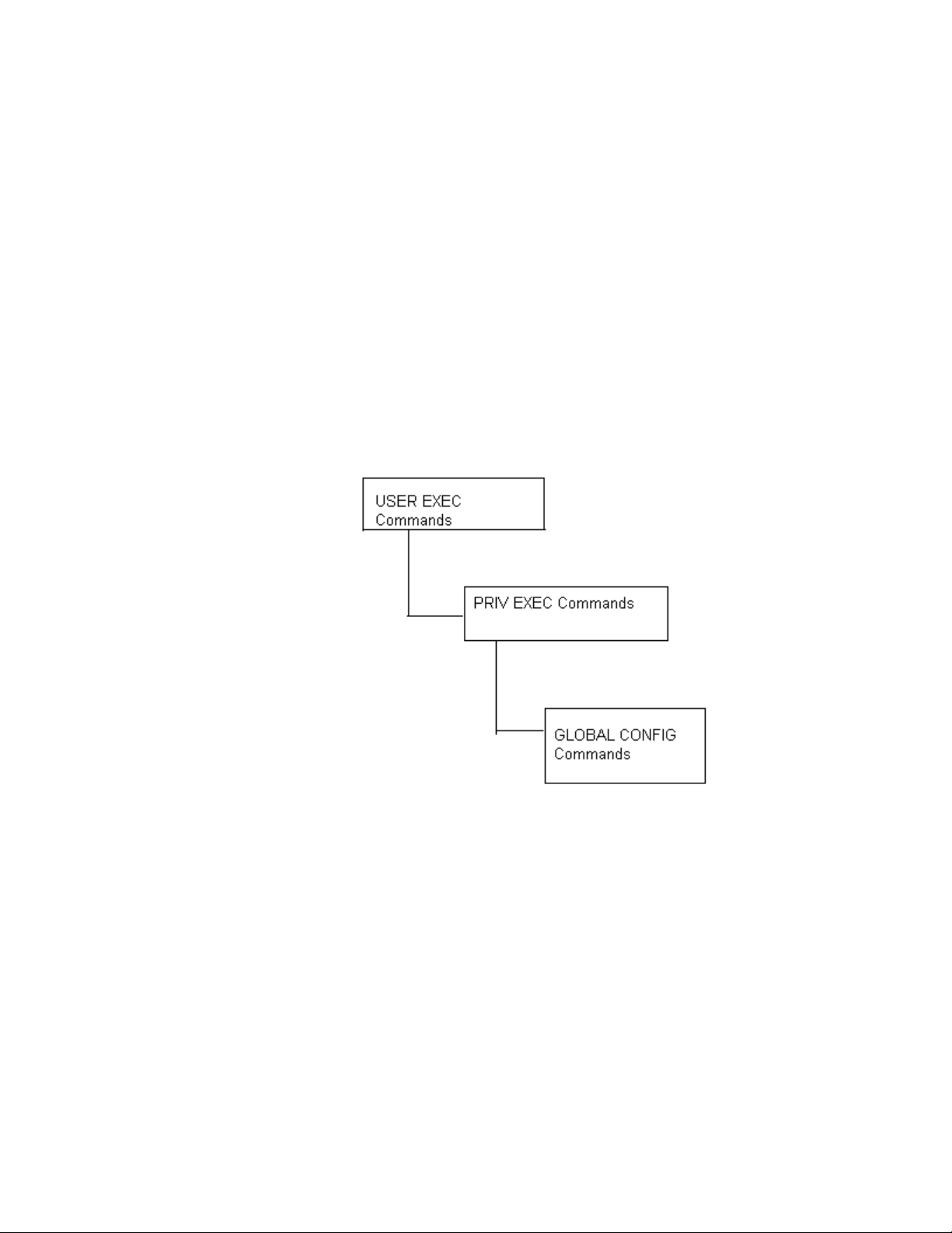
Use specific commands to navigate from one command mode to another. The standard order is:
USER EXEC mode, PRIV EXEC mode and GLOBAL CONFIG mode.
FIGURE 1 Hierarchy of User Modes
Command Modes
A session generally begins in the USER EXEC mode (one of the two access levels of the EXEC
mode). For security, only a limited subset of EXEC commands are available in the USER EXEC
mode. This level is reserved for tasks that do not change the device’s (wireless controller, service
platform, or AP) configuration.
rfs7000-37FABE>
The system prompt signifies the device name and the last three bytes of the device MAC address.
To access commands, enter the PRIV EXEC mode (the second access level for the EXEC mode).
Once in the PRIV EXEC mode, enter any EXEC command. The PRIV EXEC mode is a superset of the
USER EXEC mode.
2 Brocade Mobility RFS Controller CLI Reference Guide
53-1003098-01
Page 22

1
rfs7000-37FABE>enable
rfs7000-37FABE#
Most of the USER EXEC mode commands are one-time commands and are not saved across device
reboots. Save the command by executing ‘commit’ command. For example, the show command
displays the current configuration and the clear command clears the interface.
Access the GLOBAL CONFIG mode from the PRIV EXEC mode. In the GLOBAL CONFIG mode, enter
commands that set general system characteristics. Configuration modes, allow you to change the
running configuration. If you save the configuration later, these commands are stored across
device reboots.
Access a variety of protocol specific (or feature-specific) modes from the global configuration mode.
The CLI hierarchy requires you to access specific configuration modes only through the global
configuration mode.
rfs7000-37FABE# configure terminal
Enter configuration commands, one per line. End with CNTL/Z.
rfs7000-37FABE(config)#
You can also access sub-modes from the global configuration mode. Configuration sub-modes
define specific features within the context of a configuration mode.
rfs7000-37FABE(config)# aaa-policy test
rfs7000-37FABE(config-aaa-policy-test)#
Tab le 1 summarizes available CLI commands.
TABLE 1 Controller CLI Modes and Commands
User Exec Mode Priv Exec Mode Global Configuration Mode
captive-portal-page-upload archive aaa-policy
change-passwd boot aaa-tacacs-policy
clear captive-portal-page-upload advanced-wips-policy
clock cd alias
create-cluster cluster br650
crypto commit br6511
device-upgrade connect br1220
help crypto br71xx
join-cluster debug br81xx
logging device-upgrade association-acl-policy
mint diff auto-provisioning-policy
no dir captive-portal
page disable clear
ping edit client-identity
revert enable client-identity-group
service erase clone
show halt customize
ssh help device
telnet join-cluster device-categorization
Brocade Mobility RFS Controller CLI Reference Guide 3
53-1003098-01
Page 23

1
TABLE 1 Controller CLI Modes and Commands
User Exec Mode Priv Exec Mode Global Configuration Mode
terminal l2tpv3 dhcp-server-policy
time-it logging dns-whitelist
traceroute mint event-system-policy
watch mkdir firewall-policy
write more global-association-list
clrscr no help
exit page host
virtual-machine (Brocade Mobility
RFS9510)
pwd inline-password-encryption
re-elect ip
reload l2tpv3
remote-debug mac
rename management-policy
revert meshpoint
rmdir meshpoint-qos-policy
self mint-policy
service nac-list
show no
ssh passpoint-policy
telnet password-encryption
terminal profile
time-it radio-qos-policy
traceroute radius-group
upgrade radius-server-policy
upgrade-abort radius-user-pool-policy
watch rename
clrscr r f-domain
exit rfs4000
virtual-machine (Brocade Mobility RFS9510) rfs7000
role-policy
routing-policy
self
smart-rf-policy
wips-policy
wlan
wlan-qos-policy
4 Brocade Mobility RFS Controller CLI Reference Guide
53-1003098-01
Page 24

NOTE
NOTE
NOTE
TABLE 1 Controller CLI Modes and Commands
User Exec Mode Priv Exec Mode Global Configuration Mode
write
clrscr
commit
do
end
exit
revert
service
show
Getting Context Sensitive Help
Enter a question mark (?) at the system prompt to display a list of commands available for each
mode. Obtain a list of arguments and keywords for any command using the CLI context-sensitive
help.
1
Use the following commands to obtain help specific to a command mode, command name,
keyword or argument:
Command Description
(prompt)# help Displays a brief description of the help system
(prompt)# abbreviated-command-entry? Lists commands in the current mode that begin with a particular
character string
(prompt)# abbreviated-command-entry<Tab> Completes a partial command name
(prompt)# ? Lists all commands available in the command mode
(prompt)# command ? Lists the available syntax options (arguments and keywords) for the
command
(prompt)# command keyword ? Lists the next available syntax option for the command
The system prompt varies depending on the configuration mode.
Enter Ctrl + V to use ? as a regular character and not as a character used for displaying context
sensitive help. This is required when the user has to enter a URL that ends with a ?
The escape character used through out the CLI is “\”. To enter a "\" use "\\" instead.
Brocade Mobility RFS Controller CLI Reference Guide 5
53-1003098-01
Page 25

1
When using context-sensitive help, the space (or lack of a space) before the question mark (?) is
significant. To obtain a list of commands that begin with a particular sequence, enter the
characters followed by a question mark (?). Do not include a space. This form of help is called word
help, because it completes a word.
rfs7000-37FABE#service?
service Service Commands
rfs7000-37FABE#service
Enter a question mark (?) (in place of a keyword or argument) to list keywords or arguments.
Include a space before the “?”. This form of help is called command syntax help. It shows the
keywords or arguments available based on the command/keyword and argument already entered.
rfs7000-37FABE#service ?
advanced-wips Advanced WIPS service commands
block-adopter-config-update Block configuration updates from the
adopter
clear Clear adoption history
cli-tables-skin Choose a formatting layout/skin for CLI
tabular outputs
cluster Cluster Protocol
copy Copy from one file to another
delete Delete sessions
delete-offline-aps Delete Access Points that are configured
but offline
force-send-config Resend configuration to the device
force-update-vm-stats Force VM statistics to be pushed up to the
NOC
load-balancing Wireless load-balancing service commands
locator Enable leds flashing on the device
mint MiNT protocol
pktcap Start packet capture
pm Process Monitor
radio Radio parameters
radius Radius test
request-full-config-from-adopter Request full configuration from the
adopter
set Set validation mode
show Show running system information
signal Send a signal to a process
smart-rf Smart-RF Management Commands
ssm Command related to ssm
start-shell Provide shell access
trace Trace a process for system calls and
signals
wireless Command related to wireless
rfs7000-37FABE#
It is possible to abbreviate commands and keywords to allow a unique abbreviation. For example,
“configure terminal” can be abbreviated as
config t. Since the abbreviated command is unique,
the controller accepts the abbreviation and executes the command.
Enter the help command (available in any command mode) to provide the following description:
rfs7000-37FABE>help
When using the CLI, help is provided at the command line when typing '?'.
6 Brocade Mobility RFS Controller CLI Reference Guide
53-1003098-01
Page 26

If no help is available, the help content will be empty. Backup until entering
a '?'
shows the help content.
There are two styles of help provided:
1. Full help. Available when entering a command argument (e.g. 'show ?'). This
will
describe each possible argument.
2. Partial help. Available when an abbreviated argument is entered. This will
display
which arguments match the input (e.g. 'show ve?').
rfs7000-37FABE>
Using the No Command
Almost every command has a no form. Use no to disable a feature or function or return it to its
default. Use the command without the
1
no keyword to re-enable a disabled feature.
Basic Conventions
Keep the following conventions in mind while working within the CLI structure:
• Use ? at the end of a command to display available sub-modes. Type the first few characters of
the sub-mode and press the tab key to add the sub-mode. Continue using ? until you reach the
last sub-mode.
• Pre-defined CLI commands and keywords are case-insensitive: cfg = Cfg = CFG. However (for
clarity), CLI commands and keywords are displayed (in this guide) using mixed case. For
example, apPolicy, trapHosts, channelInfo.
• Enter commands in uppercase, lowercase, or mixed case. Only passwords are case sensitive.
Using CLI Editing Features and Shortcuts
A variety of shortcuts and edit features are available. The following sections describe these
features:
• Moving the Cursor on the Command Line
• Completing a Partial Command Name
• Command Output pagination
Moving the Cursor on the Command Line
Tab le 2 shows the key combinations or sequences to move the command line cursor. Ctrl defines
the control key, which must be pressed simultaneously with its associated letter key. Esc means the
escape key (which must be pressed first), followed by its associated letter key. Keys are not case
sensitive. Specific letters are used to provide an easy way of remembering their functions. In
Tab le 2, bold characters indicate the relation between a letter and its function.
Brocade Mobility RFS Controller CLI Reference Guide 7
53-1003098-01
Page 27

1
TABLE 2 Keystrokes Details
Keystrokes Function Summary Function Details
Left Arrow
or
Ctrl-B
Right Arrow or Ctrl-F Forward character Moves the cursor one character to the right
Esc- B Back word Moves the cursor back one word
Esc- F Forward word Moves the cursor forward one word
Ctrl-A Beginning of line Moves the cursor to the beginning of the command line
Ctrl-E End of line Moves the cursor to the end of the command line
Ctrl-D Deletes the current character
Ctrl-U Deletes text up to cursor
Ctrl-K Deletes from the cursor to end of the line
Ctrl-P Obtains the prior command from memory
Ctrl-N Obtains the next command from memory
Esc-C Converts the letter at the cursor to uppercase
Esc-L Converts the letter at the cursor to lowercase
Esc-D Deletes the remainder of a word
Ctrl-W Deletes the word up to the cursor
Ctrl-Z Returns to the root prompt
Ctrl-T Transposes the character to the left of the cursor with the
Ctrl-L Clears the screen
Back character Moves the cursor one character to the left
When entering a command that extends beyond a single line,
press the Left Arrow or Ctrl-B keys repeatedly to move back to the
system prompt.
character located at the cursor
Completing a Partial Command Name
If you cannot remember a command name (or if you want to reduce the amount of typing you have
to perform), enter the first few letters of a command, then press the Tab key. The command line
parser completes the command if the string entered is unique to the command mode. If your
keyboard does not have a Tab key, press Ctrl-L.
The CLI recognizes a command once you have entered enough characters to make the command
unique. If you enter “conf” within the privileged EXEC mode, the CLI associates the entry with the
configure command, since only the configure command begins with
In the following example, the CLI recognizes a unique string in the privileged EXEC mode when the
Tab key is pressed:
rfs7000-37FABE# conf<Tab>
rfs7000-37FABE# configure
When using the command completion feature, the CLI displays the full command name. The
command is not executed until the Return or Enter key is pressed. Modify the command if the full
command was not what you intended in the abbreviation. If entering a set of characters (indicating
more than one command), the system lists all commands beginning with that set of characters.
8 Brocade Mobility RFS Controller CLI Reference Guide
conf.
53-1003098-01
Page 28

1
NOTE
Enter a question mark (?) to obtain a list of commands beginning with that set of characters. Do not
leave a space between the last letter and the question mark (?).
For example, entering U lists all commands available in the current command mode:
rfs7000-37FABE#co?
commit Commit all changes made in this session
configure Enter configuration mode
connect Open a console connection to a remote device
copy Copy from one file to another
rfs7000-37FABE#
The characters entered before the question mark are reprinted to the screen to complete the
command entry.
Command Output pagination
Output often extends beyond the visible screen length. For cases where output continues beyond
the screen, the output is paused and a
--More--
prompt displays at the bottom of the screen. To resume the output, press the Enter key to scroll
down one line or press the Spacebar to display the next full screen of output.
Creating Profiles
Profiles are sort of a ‘template’ representation of configuration. The system has:
• a default profile for each of the following devices:
• Brocade Mobility RFS4000, Brocade Mobility RFS6000, Brocade Mobility RFS7000
• a default profile for each of the following service platforms:
• Brocade Mobility RFS9510
• a default profile for each of the following access points:
Supported in the following platforms:
• Access Points — Brocade Mobility 650 Access Point, Brocade Mobility 6511 Access Point,
Brocade Mobility 1220 Access Point, Brocade Mobility 71XX Access Point, Brocade
Mobility 1240 Access Point
• Wireless Controllers — Brocade Mobility RFS4000, Brocade Mobility RFS6000, Brocade
Mobility RFS7000
• Service Platforms — Brocade Mobility RFS9510
To modify the default profile to assign an IP address to the management port:
rfs7000-37FABE(config)#profile rfs7000 default-rfs7000
rfs7000-37FABE(config-profile-default-rfs7000)#interface me1
rfs7000-37FABE(config-profile-default-rfs7000-if-me1)#ip address
172.16.10.2/24
rfs7000-37FABE(config-profile-default-rfs7000-if-me1)#commit
rfs7000-37FABE(config-profile-default-rfs7000)#exit
rfs7000-37FABE(config)#
Brocade Mobility RFS Controller CLI Reference Guide 9
53-1003098-01
Page 29

1
The following command displays a default Brocade Mobility 71XX Access Point profile:
rfs7000-37FABE(config)#profile br71xx default-br71xx
rfs7000-37FABE(config-profile-default-br71xx)#
rfs7000-37FABE(config-profile-default-br71xx)#show context
profile br71xx default-br71xx
autoinstall configuration
autoinstall firmware
device-upgrade persist-images
crypto ikev1 policy ikev1-default
isakmp-proposal default encryption aes-256 group 2 hash sha
crypto ikev2 policy ikev2-default
isakmp-proposal default encryption aes-256 group 2 hash sha
crypto ipsec transform-set default esp-aes-256 esp-sha-hmac
crypto ikev1 remote-vpn
crypto ikev2 remote-vpn
crypto auto-ipsec-secure
crypto remote-vpn-client
interface radio1
interface radio2
interface radio3
interface ge1
ip dhcp trust
qos trust dscp
qos trust 802.1p
interface ge2
ip dhcp trust
qos trust dscp
--More--
Change the default profile by creating vlan 150 and mapping to ge3 Physical interface
Logon to the controller in config mode and follow the procedure below:
rfs7000-37FABE(config-profile-default-rfs7000)# interface vlan 150
rfs7000-37FABE(config-profile-default-rfs7000-if-vlan150)# ip address
192.168.150.20/24
rfs7000-37FABE(config-profile-default-rfs7000-if-vlan150)# exit
rfs7000-37FABE(config-profile-default-rfs7000)# interface ge 3
rfs7000-37FABE(config-profile-default-rfs7000-if-ge3)# switchport access vlan
150
rfs7000-37FABE(config-profile-default-rfs7000-if-ge3)# commit write
[OK]
rfs7000-37FABE(config-profile-default-rfs7000-if-ge3)# show interface vlan 150
Interface vlan150 is UP
Hardware-type: vlan, Mode: Layer 3, Address: 00-15-70-37-FA-BE
Index: 8, Metric: 1, MTU: 1500
IP-Address: 192.168.150.20/24
input packets 43, bytes 12828, dropped 0, multicast packets 0
input errors 0, length 0, overrun 0, CRC 0, frame 0, fifo 0, missed 0
output packets 0, bytes 0, dropped 0
output errors 0, aborted 0, carrier 0, fifo 0, heartbeat 0, window 0
collisions 0
Viewing Configured APs
To view previously configured APs, enter the following command:
10 Brocade Mobility RFS Controller CLI Reference Guide
53-1003098-01
Page 30

1
rfs7000-37FABE(config)#show wireless br configured
-----------------------------------------------------------------------------
------- IDX NAME MAC PROFILE RF-DOMAIN ADOPTED-BY
-----------------------------------------------------------------------------
------- 1 br71xx-4AA708 00-04-96-4A-A7-08 default-br71xx default
un-adopted
2 br71xx-11E6C4 00-23-68-11-E6-C4 default-br71xx default
un-adopted
3 br650-000001 00-A0-F8-00-00-01 default-br650 default
un-adopted
-----------------------------------------------------------------------------
-------rfs7000-37FABE(config)#
Remote Administration
A terminal server may function in remote administration mode if either the terminal services role is
not installed on the machine or the client used to invoke the session has enabled the admin
controller.
• A terminal emulation program running on a computer connected to the serial port on the
controller. The serial port is located on the front of the controller.
• A Telnet session through a Secure Shell (SSH) over a network. The Telnet session may or may
not use SSH depending on how the controller is configured. Brocade recommends using SSH
for remote administration tasks.
Configuring Telnet for Management Access
Login through the serial console. Perform the following:
1. A session generally begins in the USER EXEC mode (one of the two access levels of the EXEC
mode).
2. Access the GLOBAL CONFIG mode from the PRIV EXEC mode.
rfs7000-37FABE> en
rfs7000-37FABE# configure terminal
Enter configuration commands, one per line. End with CNTL/Z.
3. Go to ‘default-management-policy’ mode.
rfs7000-37FABE(config)# management-policy ?
rfs7000-37FABE(config)# management-policy default
rfs7000-37FABE(config-management-policy-default)#
4. Enter Telnet and the port number at the command prompt. The port number is optional. The
default port is 23. Commit the changes after every command. Telnet is enabled.
rfs7000-37FABE(config-management-policy-default)# telnet
rfs7000-37FABE(config-management-policy-default)# commit write
5. Connect to the controller through Telnet using its configured IP address. Use the following
credentials when logging on to the device for the first time:
User Name admin
Password admin123
Brocade Mobility RFS Controller CLI Reference Guide 11
53-1003098-01
Page 31

1
When logging into the controller for the first time, you are prompted to change the password.
To change user credentials:
1. Enter the username, password, role and access details.
rfs7000-37FABE(config-management-policy-default)#user testuser password
admin123
role helpdesk access all
rfs7000-37FABE(config-management-policy-default)# commit
rfs7000-37FABE(config-management-policy-default)#show context
management-policy default
telnet
http server
https server
ssh
user admin password 1
ba7da2bf2f7945af1d3ae1b8b762b541bd5bac1f80a54cd4488f38ed44b91ecd role
superuser access all
user operator password 1
0be97e9e30d29dfc4733e7c5f74a7be54570c2450e855cea1a696b0558a40401 role monitor
access all
user testuser password 1
bca381b5b93cddb0c209e1da8a9d387fa09bfae14cc987438a4d144cb516ffcb role
helpdesk access all
snmp-server community public ro
snmp-server community private rw
snmp-server user snmptrap v3 encrypted des auth md5 0
snmp-server user snmpoperator v3 encrypted des auth md5 0 operator
snmp-server user snmpmanager v3 encrypted des auth md5 0
rfs7000-37FABE(config-management-policy-default)#
2. Logon to the Telnet console and provide the user details configured in the previous step to
access the controller.
rfs7000 release 5.5.0.0-018D
rfs7000-37FABE login: testuser
Password:
Welcome to CLI
Starting CLI...
rfs7000-37FABE>
Configuring SSH
By default, SSH is enabled from the factory settings on the controller. The controller requires an IP
address and login credentials.
To enable SSH access in the default profile, login through the serial console. Perform the following:
1. Access the GLOBAL CONFIG mode from the PRIV EXEC mode.
rfs7000-37FABE> en
rfs7000-37FABE# configure
Enter configuration commands, one per line. End with CNTL/Z.
2. Go to ‘default-management-policy’ mode.
rfs7000-37FABE(config)# management-policy default
rfs7000-37FABE(config-management-policy-default)#
3. Enter SSH at the command prompt.
rfs7000-37FABE(config-management-policy-default)# ssh
12 Brocade Mobility RFS Controller CLI Reference Guide
53-1003098-01
Page 32

4. Log into the controller through SSH using appropriate credentials.
5. Use the following credentials when logging on to the device for the first time:
User Name admin
Password admin123
When logging into the controller for the first time, you are prompted to change the password.
To change the user credentials:
rfs7000 release 5.5.0.0-018D
rfs7000-37FABE login: testuser
Password:
Welcome to CLI
Starting CLI...
rfs7000-37FABE>
1
Brocade Mobility RFS Controller CLI Reference Guide 13
53-1003098-01
Page 33

Chapter
USER EXEC MODE COMMANDS
Logging in to the wireless controller places you within the USER EXEC command mode. Typically, a
login requires a user name and password. You have three login attempts before the connection
attempt is refused. USER EXEC commands (available at the user level) are a subset of the
commands available at the privileged level. In general, USER EXEC commands allow you to connect
to remote devices, perform basic tests, and list system information.
To list available USER EXEC commands, use ? at the command prompt. The USER EXEC prompt
consists of the device host name followed by an angle bracket (>).
<DEVICE>>?
Command commands:
captive-portal-page-upload Captive portal advanced page upload
change-passwd Change password
clear Clear
clock Configure software system clock
cluster Cluster commands
commit Commit all changes made in this session
connect Open a console connection to a remote device
create-cluster Create a cluster
crypto Encryption related commands
debug Debugging functions
device-upgrade Device firmware upgrade
disable Turn off privileged mode command
enable Turn on privileged mode command
help Description of the interactive help system
join-cluster Join the cluster
l2tpv3 L2tpv3 protocol
logging Modify message logging facilities
mint MiNT protocol
no Negate a command or set its defaults
page Toggle paging
ping Send ICMP echo messages
revert Revert changes
service Service Commands
show Show running system information
smart-cache Content Cache Operation
ssh Open an ssh connection
telnet Open a telnet connection
terminal Set terminal line parameters
time-it Check how long a particular command took between
request and completion of response
traceroute Trace route to destination
virtual-machine Virtual Machine
watch Repeat the specific CLI command at a periodic
interval
write Write running configuration to memory or
terminal
2
clrscr Clears the display screen
exit Exit from the CLI
Brocade Mobility RFS Controller CLI Reference Guide 15
53-1003098-01
Page 34

2
<DEVICE>>
User Exec Commands
Tab le 1 summarizes the User Exec Mode commands.
TABLE 1 User Exec Mode Commands
Command Description Reference
captive-portal-page-u
pload
change-passwd Changes the password of a logged user page 19
clear Resets the last saved command page 19
clock Configures the system clock page 26
cluster Accesses the cluster context page 27
connect Establishes a console connection to a remote device page 28
create-cluster Creates a new cluster on a specified device page 29
crypto Enables encryption page 30
device-upgrade Configures device firmware upgrade settings page 39
disable Turns off (disables) the privileged mode command set page 49
enable Turns on (enables) the privileged mode command set page 50
join-cluster Adds a device (access point, wireless controller, or service platform) to an existing cluster
l2tpv3 Establishes or brings down Layer 2 Tunneling Protocol Version 3 (L2TPV3) tunnels page 51
logging Modifies message logging facilities page 53
mint Configures MiNT protocol page 54
no Negates a command or sets its default page 55
page Toggles a device’s (access point, wireless controller, or service platform) paging function page 59
ping Sends ICMP echo messages to a user-specified location page 59
ssh Opens an SSH connection between two network devices page 60
telnet Opens a Telnet session page 61
terminal Sets the length and width of the terminal window page 62
time-it Verifies the time taken by a particular command between request and response page 62
traceroute Traces the route to its defined destination page 63
watch Repeats a specific CLI command at a periodic interval page 64
virtual-machine Installs, configures, and monitors the status of virtual machines (VMs). This command is
clrscr Clears the display screen page 385
commit Commits (saves) changes made in the current session page 386
help Displays the interactive help system page 387
revert Reverts changes to their last saved configuration page 394
Uploads captive portal advanced pages page 17
page 50
of devices
page 65
specific to the Brocade Mobility RFS9510 series service platforms.
16 Brocade Mobility RFS Controller CLI Reference Guide
53-1003098-01
Page 35

TABLE 1 User Exec Mode Commands (Continued)
Command Description Reference
2
service Invokes service commands to troubleshoot or debug
configurations
show Displays running system information page 429
write Writes information to memory or terminal page 425
exit Ends the current CLI session and closes the session window page 65
(config-if) instance
page 394
captive-portal-page-upload
User Exec Commands
Uploads captive portal advanced pages
Supported in the following platforms:
• Access Points — Brocade Mobility 650 Access Point, Brocade Mobility 6511 Access Point,
Brocade Mobility 1220 Access Point, Brocade Mobility 71XX Access Point, Brocade
Mobility 1240 Access Point
• Wireless Controllers — Brocade Mobility RFS4000, Brocade Mobility RFS6000, Brocade
Mobility RFS7000
• Service Platforms — Brocade Mobility RFS9510
Syntax:
captive-portal-page-upload [<CAPTIVE-PORTAL-NAME>|cancel-upload|load-file]
captive-portal-page-upload <CAPTIVE-PORTAL-NAME>
[<MAC/HOSTNAME>|all|rf-domain]
captive-portal-page-upload <CAPTIVE-PORTAL-NAME> [<MAC/HOSTNAME>|all]
{upload-time <TIME>}
captive-portal-page-upload <CAPTIVE-PORTAL-NAME> rf-domain
[<DOMAIN-NAME>|all]
{from-controller} {(upload-time <TIME>)}
captive-portal-page-upload cancel-upload [<MAC/HOSTNAME>|all|on rf-domain
[<DOMAIN-
NAME>|all]]
captive-portal-page-upload load-file <CAPTIVE-PORTAL-NAME> <URL>
Parameters
captive-portal-page-upload <CAPTIVE-PORTAL-NAME> [<MAC/HOSTNAME>|all]
{upload-time <TIME>}
captive-portal-page-upload
<CAPTIVE-PORTAL-NAME>
<MAC/HOSTNAME> Uploads to a specified AP
Uploads advanced pages of the captive-portal identified by the <CAPTIVE-PORTAL-NAME> parameter
• <CAPTIVE-PORTAL-NAME> – Specify the captive portal’s name (should be existing and configured).
• <MAC/HOSTNAME> – Specify AP’s MAC address or hostname.
all Uploads to all APs
upload-time <TIME> Optional. Configures an AP upload time
• <TIME> – Specify upload time in the MM/DD/YYYY-HH:MM or HH:MM format.
Brocade Mobility RFS Controller CLI Reference Guide 17
53-1003098-01
Page 36

2
captive-portal-page-upload <CAPTIVE-PORTAL-NAME> rf-domain [<DOMAINNAME>|all]
{from-controller} {(upload-time <TIME>)}
captive-portal-page-upload
<CAPTIVE-PORTAL-NAME>
rf-domain
[<DOMAIN-NAME>|all]
from-controller Optional. Uploads to APs from the adopted device
upload-time <TIME> Optional. Configures an AP upload time
captive-portal-page-upload
cancel-upload
cancel-upload
[<MAC/HOSTNAME>|
all|on rf-domain
[<DOMAIN-NAME>|
all]
Uploads advanced pages of the captive portal identified by the <CAPTIVE-PORTAL-NAME> parameter
• <CAPTIVE-PORTAL-NAME> – Specify captive portal’s name (should be existing and configured).
Uploads to all APs within a specified RF Domain or all RF Domains
• <DOMAIN-NAME> – Uploads to APs within a specified RF Domain. Specify the RF Domain name.
• all – Uploads to APs across all RF Domains
• <TIME> – Specify upload time in the MM/DD/YYYY-HH:MM or HH:MM format.
captive-portal-page-upload cancel-upload [<MAC/HOSTNAME>|all|on rf-domain
[<DOMAIN-NAME>|all]]
Cancels a scheduled AP upload
Select one of the following options:
• <MAC/HOSTNAME> – Cancels scheduled upload to a specified AP. Specify the AP’s MAC address or
hostname
• all – Cancels all scheduled AP uploads
• on rf- domain – Cancels all scheduled uploads within a specified RF Domain or all RF Domains
• <DOMAIN-NAME> – Cancels scheduled uploads within a specified RF Domain. Specify
RF Domain name.
• all – Cancels scheduled uploads across all RF Domains
captive-portal-page-upload
load-file
<CAPTIVE-PORTAL-NAME>
<URL>
Example
captive-portal-page-upload load-file <CAPTIVE-PORTAL-NAME> <URL>
Loads captive-portal advanced pages
Specify the captive portal’s name and location. The captive portal should be existing and configured.
• <URL> – Specifies file location in the following format:
tftp://<hostname|IP>[:port]/path/file
ftp://<user>:<passwd>@<hostname|IP>[:port]/path/file
sftp://<user>:<passwd>@<hostname|IP>[:port]>/path/file
http://<hostname|IP>[:port]/path/file
cf:/path/file
usb<n>:/path/file
rfs4000-229D58>captive-portal-page-upload test1 00-04-96-4A-A7-08 upload-time
03/01/2013-12:30
-----------------------------------------------------------------------------
-- CONTROLLER STATUS MESSAGE
-----------------------------------------------------------------------------
-- 00-23-68-22-9D-58 Fail Failed to initiate page upload
-----------------------------------------------------------------------------
--rfs4000-229D58>
rfs4000-229D58>captive-portal-page-upload cancel-upload 00-04-96-4A-A7-08
18 Brocade Mobility RFS Controller CLI Reference Guide
53-1003098-01
Page 37

2
-----------------------------------------------------------------------------
-- CONTROLLER STATUS MESSAGE
-----------------------------------------------------------------------------
-- 00-23-68-22-9D-58 Success Cancelled upgrade of 1 APs
-----------------------------------------------------------------------------
--rfs4000-229D58>
change-passwd
User Exec Commands
Changes the password of a logged user. When this command is executed without any parameters,
the password can be changed interactively.
Supported in the following platforms:
• Access Points — Brocade Mobility 650 Access Point, Brocade Mobility 6511 Access Point,
Brocade Mobility 1220 Access Point, Brocade Mobility 71XX Access Point, Brocade
Mobility 1240 Access Point
• Wireless Controllers — Brocade Mobility RFS4000, Brocade Mobility RFS6000, Brocade
Mobility RFS7000
• Service Platforms — Brocade Mobility RFS9510
Syntax:
change-passwd {<OLD-PASSWORD>} <NEW-PASSWORD>
Parameters
change-passwd {<OLD-PASSWORD>} <NEW-PASSWORD>
<OLD-PASSWORD> Optional. Specify the password to be changed.
<NEW-PASSWORD> Specify the new password.
NOTE: The password can also be changed interactively. To do so, press [Enter] after the command.
Usage Guidelines:
A password must be from 1 - 64 characters.
Example
rfs7000-37FABE>change-passwd
Enter old password:
Enter new password:
Password for user 'admin' changed successfully
Please write this password change to memory(write memory) to be persistent.
rfs7000-37FABE#write memory
OK
rfs7000-37FABE>
clear
User Exec Commands
Brocade Mobility RFS Controller CLI Reference Guide 19
53-1003098-01
Page 38

2
NOTE
Clears parameters, cache entries, table entries, and other similar entries. The clear command is
available for specific commands only. The information cleared, using this command, depends on
the mode where the clear command is executed.
Supported in the following platforms:
• Access Points — Brocade Mobility 650 Access Point, Brocade Mobility 6511 Access Point,
Brocade Mobility 1220 Access Point, Brocade Mobility 71XX Access Point, Brocade
Mobility 1240 Access Point
• Wireless Controllers — Brocade Mobility RFS4000, Brocade Mobility RFS6000, Brocade
Mobility RFS7000
• Service Platforms — Brocade Mobility RFS9510
Refer to the interface details below when using clear
- ge <index> – Brocade Mobility RFS4000 supports 5 GEs, Brocade Mobility RFS6000 supports 8
GEs
- me1 – Available in both Brocade Mobility RFS7000 and Brocade Mobility RFS6000
- up1 – Uplink interface on Brocade Mobility RFS4000
Syntax:
clear
[arp-cache|cdp|counters|crypto|event-history|gre|ip|lldp|mac-address-table|
mint|role|rtls|smart-cache|spanning-tree|vrrp]
clear arp-cache {on <DEVICE-NAME>}
clear [cdp|lldp] neighbors {on <DEVICE-NAME>}
clear counters [br|radio|wireless-client]
clear counters [br {<MAC>}|radio {<MAC/DEVICE-NAME>} {<1-3>}|wireless-client
{<MAC>}]
{(on <DEVICE-OR-DOMAIN-NAME>)}
clear crypto [ike|ipsec] sa
clear crypto ike sa [<IP>|all] {on <DEVICE-NAME>}
clear crypto ipsec sa {on <DEVICE-NAME>}
clear event-history
clear gre stats {on <DEVICE-NAME>}
clear ip [dhcp|ospf]
clear ip dhcp bindings [<IP>|all] {on <DEVICE-NAME>}
clear ip ospf process {on <DEVICE-NAME>}
clear mac-address-table {address|interface|vlan} {on <DEVICE-NAME>}
clear mac-address-table {address <MAC>|vlan <1-4094>} {on <DEVICE-NAME>}
clear mac-address-table interface [<IF-NAME>|ge <1-X>|port-channel <1-X>|
t1e1 <1-4> <1-1>|up <1-X>|vmif <1-X>|xge <1-4>] {on <DEVICE-NAME>}
clear mint mlcp history {on <DEVICE-NAME>}
clear role ldap-stats {on <DEVICE-NAME>}
20 Brocade Mobility RFS Controller CLI Reference Guide
53-1003098-01
Page 39

clear rtls [aeroscout|ekahau]
clear rtls [aeroscout|ekahau] {<DEVICE-NAME> {on <DEVICE-OR-DOMAIN-NAME>}|
on <DEVICE-OR-DOMAIN-NAME>}
clear spanning-tree detected-protocols {interface|on}
clear spanning-tree detected-protocols {on <DEVICE-NAME>}
clear spanning-tree detected-protocols {interface [<INTERFACE-NAME>|ge
<1-5>|me1|
port-channel <1-3>|pppoe1|up1|vlan <1-4094>|wwan1]} {on
<DEVICE-NAME>}
clear vrrp [error-stats|stats] {on <DEVICE-NAME>}
Parameters
clear arp-cache {on <DEVICE-NAME>}
arp-cache Clears Address Resolution Protocol (ARP) cache entries on a AP, wireless controller, or service platform.
This protocol matches the layer 3 IP addresses to the layer 2 MAC addresses.
on <DEVICE-NAME> Optional. Clears ARP cache entries on a specified device
• <DEVICE-NAME> – Specify the name of the AP, wireless controller, or service platform.
clear [cdp|lldp] neighbors {on <DEVICE-NAME>}
cdp Clears Cisco Discovery Protocol (CDP) table entries
lldp Clears Link Layer Discovery Protocol (LLDP) table entries
neighbors Clears CDP or LLDP neighbor table entries based on the option selected in the preceding step
on <DEVICE-NAME> Optional. Clears CDP or LLDP neighbor table entries on a specified device
• <DEVICE-NAME> – Specify the name of the AP, wireless controller, or service platform.
2
clear counters [br {<MAC>}|radio {<MAC/DEVICE-NAME>} {<1-3>}|wireless-client
{<MAC>}] {(on <DEVICE-OR-DOMAIN-NAME>)}
counters Clears counters based on the parameters passed. The options are: AP, radio, and wireless clients.
br <MAC> Clears counters for all APs or a specified AP
• <MAC> – Optional. Specify the AP’s MAC address.
If no MAC address is specified, all AP counters are cleared.
radio
<MAC/DEVICE-NAME>
<1-3>
Clears radio interface counters on a specified device or on all devices
• <MAC/DEVICE-NAME> – Optional. Specify the device’s hostname or MAC address. Optionally, append
the radio interface number (to the radio ID) using one of the following formats: AA-BB-CC-DD-EE-FF:RX
or HOSTNAME:RX (where RX is the interface number).
• <1-3> – Optional. Identifies the radio interface by its index. Specify the radio interface
index, if not specified as part of the radio ID.
If no device name or MAC address is specified, all radio interface counters are cleared.
wireless-client <MAC> Clears counters for all wireless clients or a specified wireless client
• <MAC> – Optional. Specify the wireless client’s MAC address.
If no MAC address is specified, all wireless client counters are cleared.
on
<DEVICE-OR-DOMAIN-NAME
>
This keyword is common to all of the above keywords.
• on <DEVICE-OR-DOMAIN-NAME> – Optional. Clears AP, radio, or wireless client counters on a specified
AP, wireless controller, service platform, or RF Domain.
Brocade Mobility RFS Controller CLI Reference Guide 21
53-1003098-01
Page 40

2
clear crypto ike sa [<IP>|all] {on <DEVICE-NAME>}
crypto Clears encryption module database
ike sa [<IP>|all] Clears Internet Key Exchange (IKE) security associations (SAs)
• <IP> – Clears IKE SA entries for the peer identified by the <IP> keyword
• all – Clears IKE SA entries for all peers
on <DEVICE-NAME> Optional. Clears IKE SA entries, for a specified peer or all peers, on a specified device
• <DEVICE-NAME> – Specify the name of the AP, wireless controller, or service platform.
clear crypto ipsec sa {on <DEVICE-NAME>}
crypto Clears encryption module database
ipsec sa
{on <DEVICE-NAME>}
gre stats Clears GRE tunnel statistics
on <DEVICE-NAME> Optional. GRE tunnel statistics on a specified device
Clears Internet Protocol Security (IPSec) database SAs
• on <DEVICE-NAME> – Optional. Clears IPSec SA entries on a specified device
• <DEVICE-NAME> – Specify the name of the AP, wireless controller, or service platform.
clear gre stats {on <DEVICE-NAME>}
• <DEVICE-NAME> – Specify the name of the AP, wireless controller, or service platform.
clear event-history
event-history Clears event history cache entries
clear ip dhcp bindings [<IP>|all] {on <DEVICE-NAME>}
ip Clears a Dynamic Host Configuration Protocol (DHCP) server’s IP address binding entries
dhcp bindings Clears DHCP connections and server bindings
<IP> Clears specific address binding entries. Specify the IP address to clear binding entries.
all Clears all address binding entries
on <DEVICE-NAME> Optional. Clears a specified address binding or all address bindings on a specified device
• <DEVICE-NAME> – Specify the name of the AP, wireless controller, or service platform.
clear ip ospf process {on <DEVICE-NAME>}
ip ospf process Clears already enabled Open Shortest Path First (OSPF) process and restarts the process
on <DEVICE-NAME> Optional. Clears OSPF process on a specified device
OSPF is a link-state interior gateway protocol (IGP). OSPF routes IP packets within a single routing domain
(autonomous system), like an enterprise LAN. OSPF gathers link state information from neighboring
routers and constructs a network topology. The topology determines the routing table presented to the
Internet Layer, which makes routing decisions based solely on the destination IP address found in IP
packets.
• <DEVICE-NAME> – Specify the name of the AP, wireless controller, or service platform.
clear mac-address-table {address <MAC>|vlan <1-4094>} {on <DEVICE-NAME>}
mac-address-table Clears the MAC address forwarding table
address <MAC> Optional. Clears a specified MAC address from the MAC address table.
• <MAC> – Specify the MAC address in one of the following formats: AA-BB-CC-DD-EE-FF or
AA:BB:CC;DD:EE:FF or AABB.CCDD.EEFF
22 Brocade Mobility RFS Controller CLI Reference Guide
53-1003098-01
Page 41

vlan <1-4094> Optional. Clears all MAC addresses for a specified VLAN
• <1-4094> – Specify the VLAN ID from 1 - 4094
on <DEVICE-NAME> Optional. Clears a single MAC entry or all MAC entries, for the specified VLAN on a specified device
• <DEVICE-NAME> – Specify the name of the AP, wireless controller, or service platform.
clear mac-address-table interface [<IF-NAME>|ge <1-X>|port-channel <1-X>|
t1e1 <1-4> <1-1>|up <1-2>|vmif <1-X>|xge <1-4>] {on <DEVICE-NAME>}
mac-address-table Clears the MAC address forwarding table
interface Clears all MAC addresses for the selected interface. Use the options available to specify the interface.
<IF-NAME> Clears MAC address forwarding table for the specified layer 2 interface (Ethernet port)
• <IF-NAME> – Specify the layer 2 interface name.
ge <1-X> Clears MAC address forwarding table for the specified GigabitEthernet interface
• <1-X> – Specify the GigabitEthernet interface index from 1 - X.
The number of Ethernet interfaces supported varies for different device types. Brocade Mobility RFS4000
supports 5 GE interfaces.
port-channel <1-X> Clears MAC address forwarding table for the specified port-channel interface
• <1-X> – Specify the port-channel interface index from 1 - X.
The number of port-channel interfaces supported varies for different device types. Brocade Mobility
RFS4000 supports 3 port-channels.
t1e1 <1-4> <1-1> Clears MAC address forwarding table for the specified T1E1L interface
• <1-4> – Specify the T1E1 interface index from 1 - 4. A maximum of 4 slots are available. Select the
slot to clear the MAC address forwarding table.
up <1-X> Clears MAC address forwarding table for the WAN Ethernet interface
The number of WAN Ethernet interfaces supported varies for different devices. The Brocade Mobility
RFS4000 and Brocade Mobility RFS6000 devices support 1 WAN Ethernet interface.
vmif <1-X> Clears MAC address forwarding table for the VM interface
• <1-X> – Specify the VM interface index from 1 - X.
The VMIF interfaces are supported only on the Brocade Mobility RFS9510 series service platforms. The
number of supported VMIFs varies for different device types.
xge <1-4> Clears MAC address forwarding table for the specified TenGigabitEthernet interface
• <1-4> – Specify the GigabitEthernet interface index from 1 - 4.
This interface is supported only on the NX9000 series service platforms.
on <DEVICE-NAME> Optional. Clears the MAC address forwarding table, for the selected interface, on a specified device
• <DEVICE-NAME> – Specify the name of the AP, wireless controller, or service platform.
2
clear mint mlcp history {on <DEVICE-NAME>}
mint Clears MiNT related information
mlcp history Clears MiNT Link Creation Protocol (MLCP) client history
on <DEVICE-NAME> Optional. Clears MLCP client history on a specified device
• <DEVICE-NAME> – Specify the name of the AP, wireless controller, or service platform.
clear role ldap-stats {on <DEVICE-NAME>}
role ldap-stats Clears LDAP server statistics
on <DEVICE-NAME> Optional. Clears LDAP server statistics on a specified device
• <DEVICE-NAME> – Specify the name of the AP, wireless controller, or service platform.
Brocade Mobility RFS Controller CLI Reference Guide 23
53-1003098-01
Page 42

2
clear rtls [aeroscout|ekahau] {<DEVICE-NAME> {on <DEVICE-OR-DOMAIN-NAME>}|
on <DEVICE-OR-DOMAIN-NAME>}
rtls Clears Real Time Location Service (RTLS) statistics
aeroscout Clears RTLS Aeroscout statistics
ekahau Clears RTLS Ekahau statistics
on <DEVICE-NAME> This keyword is common to the ‘aeroscout’ and ‘ekahau’ parameters.
• on <DEVICE-NAME> – Optional. Clears Aeroscout or Ekahau RTLS statistics AP, wireless controller,
or service platform
on
<DEVICE-OR-DOMAIN-NAME>
spanning-tree Clears spanning tree entries on an interface, and restarts protocol migration
detected-protocols Restarts protocol migration
on <DEVICE-NAME> Optional. Clears spanning tree entries on a specified device
spanning-tree Clears spanning tree entries on an interface and restarts protocol migration
detected-protocols Restarts protocol migration
interface
[<INTERFACE-NAME>|
ge <1-5>|me1|
port-channel <1-3>|
pppoe1|up1|
vlan <1-4094>|
wwan1]
on <DEVICE-NAME> Optional. Clears spanning tree entries on a specified device
This keyword is common to the ‘aeroscout’ and ‘ekahau’ parameters.
• on <DEVICE-OR-DOMAIN-NAME> – Optional. Clears Aeroscout or Ekahau RTLS statistics on a
specified AP, wireless controller, service platform, or RF Domain
clear spanning-tree detected-protocols {on <DEVICE-NAME>}
• <DEVICE-NAME> – Specify the name of the AP, wireless controller, or service platform.
clear spanning-tree detected-protocols {interface [<INTERFACE-NAME>|ge <1-5>|
me1|port-channel <1-3>|pppoe1|up1|vlan <1-4094>|wwan1]} {on <DEVICE-NAME>}
Optional. Clears spanning tree entries on different interfaces
• <INTERFACE-NAME> – Clears detected spanning tree entries on a specified interface. Specify
the interface name.
• ge <1-5> – Clears detected spanning tree entries for the selected GigabitEthernet interface.
Select the GigabitEthernet interface index from 1 - 5.
• me1 – Clears FastEthernet interface status
• port-channel <1-3> – Clears detected spanning tree entries for the selected port channel
interface. Select the port channel index from 1 - 3.
• pppoe1 – Clears detected spanning tree entries for Point-to-Point Protocol over Ethernet
(PPPoE) interface
• up1 – Clears detected spanning tree entries for the WAN Ethernet interface
• vlan <1-4094> – Clears detected spanning tree entries for the selected VLAN interface. Select
a Switch Virtual Interface (SVI) VLAN ID from 1- 4094.
• wwan1 – Clears detected spanning tree entries for wireless WAN interface.
• <DEVICE-NAME> – Specify the name of the AP, wireless controller, or service platform.
clear vrrp [error-stats|stats] {on <DEVICE-NAME>}
vrrp Clears a device’s Virtual Router Redundancy Protocol (VRRP) statistics
VRRP allows a pool of routers to be advertized as a single virtual router. This virtual router is
configured by hosts as their default gateway. VRRP elects a master router, from this pool, and
assigns it a virtual IP address. The master router routes and forwards packets to hosts on the same
subnet. When the master router fails, one of the backup routers is elected as the master and its IP
address is mapped to the virtual IP address.
error-stats Clears global error statistics
24 Brocade Mobility RFS Controller CLI Reference Guide
53-1003098-01
Page 43

stats Clears VRRP related statistics
on <DEVICE-NAME> This following keywords are common to the ‘error-stats’ and ‘stats’ parameters:
• on <DEVICE-NAME> – Optional. Clears VRRP statistics on a specified device
• <DEVICE-NAME> – Specify the name of the AP, wireless controller, or
service platform.
Example
rfs4000-229D58>clear event-history
rfs4000-229D58>clear spanning-tree detected-protocols interface port-channel 1
on rfs4000-229D58
rfs4000-229D58>clear spanning-tree detected-protocols interface ge 1
rfs4000-229D58>clear lldp neighbors
rfs4000-229D58>show cdp neighbors
-----------------------------------------------------------------------------
-- Device ID Platform Local Intrfce Port ID Duplex
-----------------------------------------------------------------------------
-- rfs4000-880DA7 RFS-4011-11110-US ge1 ge1 full
rfs7000-37FDF2 RFS-7010-1000-WR ge1 ge1 full
rfs6000-434CAA Brocade Mobility RFS6000 ge1 ge1
full
br7131-139B34 Brocade Mobility 7131 Access PointN ge1
ge1 full
-----------------------------------------------------------------------------
---rfs4000-229D58>
2
rfs4000-229D58>clear cdp neighbors
rfs4000-229D58>show cdp neighbors
-----------------------------------------------------------------------------
-- Device ID Platform Local Intrfce Port ID Duplex
-----------------------------------------------------------------------------
---
-----------------------------------------------------------------------------
---
rfs4000-229D58>
rfs4000-229D58>clear role ldap-stats
rfs4000-229D58>show role ldap-stats
No ROLE LDAP statistics found.
rfs4000-229D58>
rfs4000-229D58>show mac-address-table
------------------------------------------------------- BRIDGE VLAN PORT MAC STATE
------------------------------------------------------- 1 1 ge5 00-02-B3-28-D1-55 forward
1 1 ge5 00-0F-8F-19-BA-4C forward
1 1 ge5 B4-C7-99-5C-FA-8E forward
Brocade Mobility RFS Controller CLI Reference Guide 25
53-1003098-01
Page 44

2
1 1 ge5 00-23-68-0F-43-D8 forward
1 1 ge5 00-15-70-38-06-49 forward
1 1 ge5 00-23-68-13-9B-34 forward
1 1 ge5 B4-C7-99-58-72-58 forward
1 1 ge5 00-15-70-81-74-2D forward
1 1 ge5 B4-C7-99-5C-FA-2B forward
1 1 ge5 00-15-70-37-FD-F2 forward
1 1 ge5 B4-C7-99-6C-88-09 forward
1 1 ge5 B4-C7-99-71-17-28 forward
1 1 ge5 5C-0E-8B-18-10-91 forward
1 1 ge5 3C-CE-73-F4-47-83 forward
1 1 ge5 00-23-68-88-0D-AC forward
1 1 ge5 00-A0-F8-68-D5-5C forward
-------------------------------------------------------Total number of MACs displayed: 16
rfs4000-229D58>
rfs4000-229D58>clear mac-address-table address 00-02-B3-28-D1-55 on
rfs4000-229D58
In the following example the first MAC address in the table has been cleared.
Now the table has only 15 entries.
rfs4000-229D58>show mac-address-table on rfs4000-229D58
------------------------------------------------------- BRIDGE VLAN PORT MAC STATE
------------------------------------------------------- 1 1 ge5 00-0F-8F-19-BA-4C forward
1 1 ge5 B4-C7-99-5C-FA-8E forward
1 1 ge5 00-23-68-0F-43-D8 forward
1 1 ge5 00-15-70-38-06-49 forward
1 1 ge5 00-23-68-13-9B-34 forward
1 1 ge5 B4-C7-99-58-72-58 forward
1 1 ge5 00-15-70-81-74-2D forward
1 1 ge5 B4-C7-99-5C-FA-2B forward
1 1 ge5 00-15-70-37-FD-F2 forward
1 1 ge5 B4-C7-99-6C-88-09 forward
1 1 ge5 B4-C7-99-71-17-28 forward
1 1 ge5 5C-0E-8B-18-10-91 forward
1 1 ge5 3C-CE-73-F4-47-83 forward
1 1 ge5 00-23-68-88-0D-AC forward
1 1 ge5 00-A0-F8-68-D5-5C forward
-------------------------------------------------------Total number of MACs displayed: 15
rfs4000-229D58>
clock
User Exec Commands
Sets a device’s system clock
Supported in the following platforms:
• Access Points — Brocade Mobility 650 Access Point, Brocade Mobility 6511 Access Point,
Brocade Mobility 1220 Access Point, Brocade Mobility 71XX Access Point, Brocade
Mobility 1240 Access Point
26 Brocade Mobility RFS Controller CLI Reference Guide
53-1003098-01
Page 45

• Wireless Controllers — Brocade Mobility RFS4000, Brocade Mobility RFS6000, Brocade
Mobility RFS7000
• Service Platforms — Brocade Mobility RFS9510
Syntax:
clock set <HH:MM:SS> <1-31> <MONTH> <1993-2035> {on <DEVICE-NAME>}
Parameters
clock set <HH:MM:SS> <1-31> <MONTH> <1993-2035> {on <DEVICE-NAME>}
clock set Sets a device’s software system clock
<HH:MM:SS> Sets the current time (in military format hours, minutes and seconds)
<1-31> Sets the numerical day of the month
<MONTH> Sets the month of the year (Jan to Dec)
<1993-2035> Sets a valid four digit year from 1993 - 2035
on <DEVICE-NAME> Optional. Sets the clock on a specified device
• <DEVICE-NAME> – Specify the name of the AP, wireless controller, or service platform.
Example
rfs4000-229D58>clock set 14:25:35 15 Feb 2013
2
rfs4000-229D58>show clock
2013-02-15 14:25:40 UTC
rfs4000-229D58>
cluster
User Exec Commands
Initiates cluster context. The cluster context provides centralized management to configure all
cluster members from any one member.
Commands executed under this context are executed on all members of the cluster.
Supported in the following platforms:
• Wireless Controllers — Brocade Mobility RFS4000, Brocade Mobility RFS6000, Brocade
Mobility RFS7000
• Service Platforms — Brocade Mobility RFS9510
Syntax:
cluster start-election
Parameters
cluster start-election
start-election Starts a new cluster master election
Example
rfs7000-37FABE>cluster start-election
rfs7000-37FABE>
Brocade Mobility RFS Controller CLI Reference Guide 27
53-1003098-01
Page 46

2
Related Commands:
create-cluster Creates a new cluster on the specified device
join-cluster Adds a wireless controller or service platform, as a member, to an existing cluster of controllers
connect
User Exec Commands
Begins a console connection to a remote device using the remote device’s MiNT ID or name
Supported in the following platforms:
• Access Points — Brocade Mobility 650 Access Point, Brocade Mobility 6511 Access Point,
Brocade Mobility 1220 Access Point, Brocade Mobility 71XX Access Point, Brocade
Mobility 1240 Access Point
• Wireless Controllers — Brocade Mobility RFS4000, Brocade Mobility RFS6000, Brocade
Mobility RFS7000
• Service Platforms — Brocade Mobility RFS9510
Syntax:
connect [mint-id <MINT-ID>|<REMOTE-DEVICE-NAME>]
Parameters
connect [mint-id <MINT-ID>|<REMOTE-DEVICE-NAME>]
mint-id <MINT-ID> Connects to the remote system using its MiNT ID
• <MINT-ID> – Specify the remote device’s MiNT ID.
<REMOTE-DEVICE-NAME> Connects to the remote system using its name
• <REMOTE-DEVICE-NAME> – Specify the remote device’s name.
Example
rfs7000-37FABE>show mint lsp-db
2 LSPs in LSP-db of 70.37.FA.BE:
LSP 68.11.E6.C4 at level 1, hostname "ap7131-11E6C4", 1 adjacencies, seqnum
LSP 70.37.FA.BE at level 1, hostname "rfs7000-37FABE", 1 adjacencies, seqnu20
rfs7000-37FABE>connect mint-id 68.11.E6.C4 ?
Entering character mode
Escape character is '^
rfs7000-37FABE>connect mint-id 68.11.E6.C4 ?
Entering character mode
Escape character is '^
Brocade Mobility 7131 Access Point release 5.5.0.0-018D
br7131-11E6C4 login: Connection closed by foreign host
rfs7000-37FABE>
]'.
rfs4000-229D58>show mint lsp-db
1 LSPs in LSP-db of 68.22.9D.58:
LSP 68.22.9D.58 at level 1, hostname "rfs4000-229D58", 0 adjacencies, seqnum
606
28 Brocade Mobility RFS Controller CLI Reference Guide
53-1003098-01
Page 47

2
rfs4000-229D58>
rfs4000-229D58>connect ?
REMOTE-DEVICE-NAME Name of remote system
mint-id MiNT protocol identifier
rfs4000-229D58>connect mint-id 68.22.9D.58
Entering character mode
Escape character is '^]'.
Brocade Mobility RFS4000 release 5.5.0.0-018D
rfs4000-229D58 login:
create-cluster
User Exec Commands
Creates a new device cluster with the specified name and assigns it an IP address and routing level
A cluster (or redundancy group) is a set of controllers or service platforms (nodes) uniquely defined
by a profile configuration. Within the cluster, members discover and establish connections to other
members and provide wireless network self-healing support in the event of member's failure.
A cluster's load balance is typically distributed evenly amongst its members. An administrator
needs to define how often the profile is load balanced for radio distribution, as radios can come
and go and members join and exit the cluster.
Supported in the following platforms:
• Wireless Controllers — Brocade Mobility RFS4000, Brocade Mobility RFS6000, Brocade
Mobility RFS7000
• Service Platforms — Brocade Mobility RFS9510
Syntax:
create-cluster name <CLUSTER-NAME> ip <IP> {level [1|2]}
Parameters
create-cluster name <CLUSTER-NAME> ip <IP> {level [1|2]}
create-cluster Creates a cluster
name
<CLUSTER-NAME>
ip <IP> Specifies the device’s IP address used for cluster creation
Configures the cluster name
• <CLUSTER-NAME> – Specify a cluster name. Define a name for the cluster name unique to its
configuration or profile support requirements. The name cannot exceed 64 characters.
• <IP> – Specify the device’s IP address in the A.B.C.D format.
level [1|2] Optional. Configures the cluster’s routing level
• 1 – Configures level 1 (local) routing
• 2 – Configures level 2 (inter-site) routing
Example
rfs7000-37FABE>create-cluster name Cluster1 ip 172.16.10.1 level 1
... creating cluster
... committing the changes
... saving the changes
Brocade Mobility RFS Controller CLI Reference Guide 29
53-1003098-01
Page 48

2
[OK]
rfs7000-37FABE>
nx6500-31FABE>create-cluster <CLUSTER-NAME>
Related Commands:
cluster Initiates cluster context. The cluster context provides centralized management to configure all cluster
members from any one member.
join-cluster Adds a device, as a member, to an existing cluster of devices
crypto
User Exec Commands
Enables digital certificate configuration and RSA Keypair management. Digital certificates are
issued by CAs and contain user or device specific information, such as name, public key, IP
address, serial number, company name etc. Use this command to generate, delete, export, or
import encrypted RSA Keypairs and generate Certificate Signing Request (CSR).
This command also enables trustpoint configuration. Trustpoints contain the CA’s identity and
configuration parameters.
Supported in the following platforms:
• Access Points — Brocade Mobility 650 Access Point, Brocade Mobility 6511 Access Point,
Brocade Mobility 1220 Access Point, Brocade Mobility 71XX Access Point, Brocade
Mobility 1240 Access Point
• Wireless Controllers — Brocade Mobility RFS4000, Brocade Mobility RFS6000, Brocade
Mobility RFS7000
• Service Platforms — Brocade Mobility RFS9510
Syntax:
crypto [key|pki]
crypto key [export|generate|import|zeroize]
crypto key export rsa <RSA-KEYPAIR-NAME> <EXPORT-TO-URL>
{background|on|passphrase}
crypto key export rsa <RSA-KEYPAIR-NAME> <EXPORT-TO-URL>
{background {on <DEVICE-NAME>}|on <DEVICE-NAME>}
crypto key export rsa <RSA-KEYPAIR-NAME> <EXPORT-TO-URL>
{passphrase <KEY-PASSPHRASE> {background {on <DEVICE-NAME>}|on
<DEVICE-NAME>}}
crypto key generate rsa <RSA-KEYPAIR-NAME> <1024-2048> {on <DEVICE-NAME>}
crypto key import rsa <RSA-KEYPAIR-NAME> <IMPORT-FROM-URL>
{background|on|passphrase}
crypto key import rsa <RSA-KEYPAIR-NAME> <IMPORT-FROM-URL>
{background {on <DEVICE-NAME>}|on <DEVICE-NAME>}
crypto key import rsa <RSA-KEYPAIR-NAME> <IMPORT-FROM-URL>
{passphrase <KEY-PASSPHRASE> {background {on <DEVICE-NAME>}|on
<DEVICE-NAME>}}
30 Brocade Mobility RFS Controller CLI Reference Guide
53-1003098-01
Page 49

2
crypto key zeroize rsa <RSA-KEYPAIR-NAME> {force {on <DEVICE-NAME>}|on
<DEVICE-NAME>}
crypto pki [authenticate|export|generate|import|zeroize]
crypto pki authenticate <TRUSTPOINT-NAME> <LOCATION-URL>
{background {on <DEVICE-NAME>}|on <DEVICE-NAME>}
crypto pki export [request|trustpoint]
crypto pki export request [generate-rsa-key|use-rsa-key] <RSA-KEYPAIR-NAME>
[autogen-subject-name|subject-name]
crypto pki export request [generate-rsa-key|use-rsa-key] <RSA-KEYPAIR-NAME>
autogen-subject-name (<EXPORT-TO-URL>,email <SEND-TO-EMAIL>,fqdn <FQDN>,
ip-address <IP>)
crypto pki export request [generate-rsa-key|use-rsa-key] <RSA-KEYPAIR-NAME>
autogen-subject-name <EXPORT-TO-URL> {background {on <DEVICE-NAME>}|
on <DEVICE-NAME>}
crypto pki export request [generate-rsa-key|use-rsa-key] <RSA-KEYPAIR-NAME>
subject-name <COMMON-NAME> <COUNTRY> <STATE> <CITY> <ORGANIZATION>
<ORGANIZATION-UNIT> (<EXPORT-TO-URL>,email <SEND-TO-EMAIL>,fqdn <FQDN>,
ip-address <IP>)
crypto pki export trustpoint <TRUSTPOINT-NAME> <EXPORT-TO-URL> {background
{on <DEVICE-NAME>}|on <DEVICE-NAME>|passphrase <KEY-PASSPHRASE> {background
{on <DEVICE-NAME>}|on <DEVICE-NAME>}}
crypto pki generate self-signed <TRUSTPOINT-NAME> [generate-rsa-key|
use-rsa-key] <RSA-KEYPAIR-NAME> [autogen-subject-name|subject-name]
crypto pki generate self-signed <TRUSTPOINT-NAME> [generate-rsa-key|
use-rsa-key] <RSA-KEYPAIR-NAME> autogen-subject-name {(email
<SEND-TO-EMAIL>,
fqdn <FQDN>,ip-address <IP>,on <DEVICE-NAME>)}
crypto pki generate self-signed <TRUSTPOINT-NAME> [generate-rsa-key|
use-rsa-key] <WORD> subject-name <COMMON-NAME> <COUNTRY> <STATE> <CITY>
<ORGANIZATION> <ORGANIZATION-UNIT> {(email <SEND-TO-EMAIL>,fqdn <FQDN>,
ip-address <IP>,on <DEVICE-NAME>)}
crypto pki import [certificate|crl|trustpoint]
crypto pki import [certificate|crl] <TRUSTPOINT-NAME> <IMPORT-FROM-URL>
{background {on <DEVICE-NAME>}|on <DEVICE-NAME>}]
crypto pki import trustpoint <TRUSTPOINT-NAME> <IMPORT-FROM-URL>
{background {on <DEVICE-NAME>}|on <DEVICE-NAME>|passphrase <KEY-PASSPHRASE>
{background {on <DEVICE-NAME>}|on <DEVICE-NAME>}}
crypto pki zeroize trustpoint <TRUSTPOINT-NAME> {del-key {on <DEVICE-NAME>}|
on <DEVICE-NAME>}
Parameters
crypto key export rsa <RSA-KEYPAIR-NAME> <EXPORT-TO-URL>
{background {on <DEVICE-NAME>}|on <DEVICE-NAME>}
key Enables RSA Keypair management. Use this command to export, import, generate, or delete a RSA key.
export rsa
<RSA-KEYPAIR-NAME>
Exports an existing RSA Keypair to a specified destination
• <RSA-KEYPAIR-NAME> – Specify the RSA Keypair name.
Brocade Mobility RFS Controller CLI Reference Guide 31
53-1003098-01
Page 50

2
<EXPORT-TO-URL> Specify the RSA Keypair destination address in the following format:
tftp://<hostname|IP>[:port]/path/file
ftp://<user>:<passwd>@<hostname|IP>[:port]/path/file
sftp://<user>@<hostname|IP>[:port]>/path/file
http://<hostname|IP>[:port]/path/file
cf:/path/file
usb<n>:/path/file
background
{on <DEVICE-NAME>}
on <DEVICE-NAME> Optional. Performs export operation on a specific device.
key Enables RSA Keypair management. Use this command to export, import, generate, or delete a RSA key.
export rsa Exports a RSA Keypair to a specified destination
<EXPORT-TO-URL>
{passphrase
<KEY-PASSPHRASE>}
on <DEVICE-NAME> Optional. Performs export operation on a specified device
Optional. Performs export operation in the background. Optionally specify the device to perform export on.
• on <DEVICE-NAME> – Optional. Performs export operation on a specific device
• <DEVICE-NAME> – Specify the name of the AP, wireless controller, or service platform.
crypto key export rsa <RSA-KEYPAIR-NAME> <EXPORT-TO-URL>
{passphrase <KEY-PASSPHRASE> {background {on <DEVICE-NAME>}|on <DEVICE-NAME>}}
• <RSA-KEYPAIR-NAME> – Specify the RSA Keypair name.
Specify the RSA Keypair destination address in the following format:
tftp://<hostname|IP>[:port]/path/file
ftp://<user>:<passwd>@<hostname|IP>[:port]/path/file
sftp://<user>@<hostname|IP>[:port]>/path/file
http://<hostname|IP>[:port]/path/file
cf:/path/file
usb<n>:/path/file
• passphrase – Optional. Encrypts RSA Keypair before exporting it
• <KEY-PASSPHRASE> – Specify a passphrase to encrypt the RSA Keypair.
• <DEVICE-NAME> – Specify the name of the AP, wireless controller, or service platform.
crypto key generate rsa <RSA-KEYPAIR-NAME> <1024-2048> {on <DEVICE-NAME>}
key Enables RSA Keypair management. Use this command to export, import, generate, or delete a RSA key.
generate rsa
<RSA-KEYPAIR-NAME>
<1024-2048>
on <DEVICE-NAME> Optional. Generates the new RSA Keypair on a specified device
Generates a new RSA Keypair
• <RSA-KEYPAIR-NAME> – Specify the RSA Keypair name.
• <1024-2048> – Sets the size of the RSA key in bits from 1024 - 2048. The default size is 1024.
• <DEVICE-NAME> – Specify the name of the AP, wireless controller, or service platform.
crypto key import rsa <RSA-KEYPAIR-NAME> <IMPORT-FROM-URL>
{background {on <DEVICE-NAME>}|on <DEVICE-NAME>}
key Enables RSA Keypair management. Use this command to export, import, generate, or delete a RSA key.
import rsa
<RSA-KEYPAIR-NAME>
32 Brocade Mobility RFS Controller CLI Reference Guide
Imports a RSA Keypair from a specified source
• <RSA-KEYPAIR-NAME> – Specify the RSA Keypair name.
53-1003098-01
Page 51

<IMPORT-FROM-URL> Specify the RSA Keypair source address in the following format:
tftp://<hostname|IP>[:port]/path/file
ftp://<user>:<passwd>@<hostname|IP>[:port]/path/file
sftp://<user>@<hostname|IP>[:port]>/path/file
http://<hostname|IP>[:por t]/path/file
cf:/path/file
usb<n>:/path/file
on <DEVICE-NAME> Optional. Performs import operation on a specified device
• <DEVICE-NAME> – Specify the name of the AP, wireless controller, or service platform.
background
{on <DEVICE-NAME>}
Optional. Performs import operation in the background
• on <DEVICE-NAME> – Optional. Performs import operation on a specified device
• <DEVICE-NAME> – Specify the name of the AP, wireless controller, or service platform.
crypto key import rsa <RSA-KEYPAIR-NAME> <IMPORT-FROM-URL>
{passphrase <KEY-PASSPHRASE> {background {on <DEVICE-NAME>}|on <DEVICE-NAME>}}
key Enables RSA Keypair management. Use this command to export, import, generate, or delete a RSA key.
import rsa
<RSA-KEYPAIR-NAME>
<IMPORT-FROM-URL>
{passphrase
<KEY-PASSPHRASE>}
Decrypts and imports a RSA Keypair from a specified source
• <RSA-KEYPAIR-NAME> – Specify the RSA Keypair name.
Specify the RSA Keypair source address in the following format:
tftp://<hostname|IP>[:port]/path/file
ftp://<user>:<passwd>@<hostname|IP>[:port]/path/file
sftp://<user>@<hostname|IP>[:port]>/path/file
http://<hostname|IP>[:port]/path/file
cf:/path/file
usb<n>:/path/file
• passphrase – Optional. Decrypts the RSA Keypair before importing it
• <KEY-PASSPHRASE> – Specify the passphrase to decrypt the RSA Keypair.
on <DEVICE-NAME> Optional. Performs import operation on a specified device
• <DEVICE-NAME> – Specify the name of the AP, wireless controller, or service platform.
2
crypto key zeroize <RSA-KEYPAIR-NAME> {force {on <DEVICE-NAME>}|on
<DEVICE-NAME>}
key Enables RSA Keypair management. Use this command to export, import, generate, or delete a RSA key.
zeroize rsa
<RSA-KEYPAIR-NAME>
force
{on <DEVICE-NAME>}
on <DEVICE-NAME> Optional. Deletes all certificates associated with the RSA Keypair on a specified device
Deletes a specified RSA Keypair
• <RSA-KEYPAIR-NAME> – Specify the RSA Keypair name.
NOTE: All device certificates associated with this key will also be deleted.
Optional. Forces deletion of all certificates associated with the specified RSA Keypair. Optionally specify a
device on which to force certificate deletion.
• <DEVICE-NAME> – Specify the name of the AP, wireless controller, or service platform.
crypto pki authenticate <TRUSTPOINT-NAME> <URL> {background {on
<DEVICE-NAME>}|
on <DEVICE-NAME>}
pki Enables Private Key Infrastructure (PKI) management. Use this command to authenticate, export,
generate, or delete a trustpoint and its associated Certificate Authority (CA) certificates.
authenticate
<TRUSTPOINT-NAME>
Brocade Mobility RFS Controller CLI Reference Guide 33
53-1003098-01
Authenticates a trustpoint and imports the corresponding CA certificate
• <TRUSTPOINT-NAME> – Specify the trustpoint name.
Page 52

2
<URL> Specify CA’s location in the following format:
tftp://<hostname|IP>[:port]/path/file
ftp://<user>:<passwd>@<hostname|IP>[:port]/path/file
sftp://<user>@<hostname|IP>[:port]>/path/file
http://<hostname|IP>[:port]/path/file
cf:/path/file
usb<n>:/path/file
NOTE: The CA certificate is imported from the specified location.
background
{on <DEVICE-NAME>}
on <DEVICE-NAME> Optional. Performs authentication on a specified device
pki Enables PKI management. Use this command to authenticate, export, generate, or delete a trustpoint and
export request Exports CSR to the CA for digital identity certificate. The CSR contains applicant’s details and RSA Keypair’s
[generate-rsa-key|
use-rsa-key]
<RSA-KEYPAIR-NAME>
autogen-subject-name Auto generates subject name from configuration parameters. The subject name identifies the certificate.
<EXPORT-TO-URL>
{background
{on <DEVICE-NAME}|
on <DEVICE-NAME>}
email
<SEND-TO-EMAIL>
fqdn <FQDN> Exports CSR to a specified Fully Qualified Domain Name (FQDN)
ip address <IP> Exports CSR to a specified device or system
Optional. Performs authentication in the background. Optionally specify a device on which to perform
authentication.
• <DEVICE-NAME> – Specify the name of the AP, wireless controller, or service platform.
crypto pki export request [generate-rsa-key|use-rsa-key] <RSA-KEYPAIR-NAME>
autogen-subject-name (<EXPORT-TO-URL>,email <SEND-TO-EMAIL>,fqdn
<FQDN>,ip-address <IP>)
its associated CA certificates.
public key.
Generates a new RSA Keypair or uses an existing RSA Keypair
• generate-rsa-key – Generates a new RSA Keypair for digital authentication
• use-rsa-key – Uses an existing RSA Keypair for digital authentication
• <RSA-KEYPAIR-NAME> – If generating a new RSA Keypair, specify a name for it. If using an existing
RSA Keypair, specify its name.
Specify the CA’s location in the following format:
tftp://<hostname|IP>[:port]/path/file
ftp://<user>:<passwd>@<hostname|IP>[:port]/path/file
sftp://<user>@<hostname|IP>[:port]>/path/file
http://<hostname|IP>[:port]/path/file
cf:/path/file
usb<n>:/path/file
NOTE: The CSR is exported to the specified location.
• background – Optional. Performs export operation in the background
• on <DEVICE-NAME> – Optional. Performs export operation on a specified device
• <DEVICE-NAME> – Specify the name of the AP, wireless controller, or service platform.
Exports CSR to a specified e-mail address
• <SEND-TO-EMAIL> – Specify the CA’s e-mail address.
• <FQDN> – Specify the CA’s FQDN.
• <IP> – Specify the CA’s IP address.
34 Brocade Mobility RFS Controller CLI Reference Guide
53-1003098-01
Page 53

crypto pki export request [generate-rsa-key|use-rsa-key] <RSA-KEYPAIR-NAME>
subject-name <COUNTRY> <STATE> <CITY> <ORGANIZATION> <ORGANIZATION-UNIT>
(<EXPORT-TO-URL>,email <SEND-TO-EMAIL>,fqdn <FQDN>,ip-address <IP>)
pki Enables PKI management. Use this command to authenticate, export, generate, or delete a trustpoint and
its associated CA certificates.
export request Exports CSR to the CA for a digital identity certificate.The CSR contains applicant’s details and RSA
Keypair’s public key.
[generate-rsa-key|
use-rsa-key]
<RSA-KEYPAIR-NAME>
Generates a new RSA Keypair or uses an existing RSA Keypair
• generate-rsa-key – Generates a new RSA Keypair for digital authentication
• use-rsa-key – Uses an existing RSA Keypair for digital authentication
• <RSA-KEYPAIR-NAME> – If generating a new RSA Keypair, specify a name for it. If
using an existing RSA Keypair, specify its name.
subject-name
<COMMON-NAME>
<COUNTRY> Sets the deployment country code (2 character ISO code)
<STATE> Sets the state name (2 to 64 characters in length)
<CITY> Sets the city name (2 to 64 characters in length)
<ORGANIZATION> Sets the organization name (2 to 64 characters in length)
<ORGANIZATION-UNIT> Sets the organization unit (2 to 64 characters in length)
<EXPORT-TO-URL>
{background
{on <DEVICE-NAME}|
on <DEVICE-NAME>}
Specifies subject name to identify the certificate
• <COMMON-NAME> – Sets the common name used with the CA certificate. The name should enable
you to identify the certificate easily (2 to 64 characters in length).
Specify the CA’s location in the following format:
tftp://<hostname|IP>[:port]/path/file
ftp://<user>:<passwd>@<hostname|IP>[:port]/path/file
sftp://<user>@<hostname|IP>[:port]>/path/file
http://<hostname|IP>[:port]/path/file
cf:/path/file
usb<n>:/path/file
NOTE: The CSR is exported to the specified location.
• background – Optional. Performs export operation in the background
• on <DEVICE-NAME> – Optional. Performs export operation on a specific device
• <DEVICE-NAME> – Specify the name of the AP, wireless controller, or service platform.
email
<SEND-TO-EMAIL>
fqdn <FQDN> Exports CSR to a specified FQDN
Exports CSR to a specified e-mail address
• <SEND-TO-EMAIL> – Specify the CA’s e-mail address.
• <FQDN> – Specify the CA’s FQDN.
ip address <IP> Exports CSR to a specified device or system
• <IP> – Specify the CA’s IP address.
2
crypto pki export trustpoint <TRUSTPOINT-NAME> <EXPORT-TO-URL>
{background {on <DEVICE-NAME>}|on <DEVICE-NAME>|passphrase <KEY-PASSPHRASE>
background {on <DEVICE-NAME>}|on <DEVICE-NAME>}}
pki Enables PKI management. Use this command to authenticate, export, generate, or delete a trustpoint and
its associated CA certificates.
export trustpoint
<TRUSTPOINT-NAME>
Exports a trustpoint along with CA certificate, Certificate Revocation List (CRL), server certificate, and
private key
• <TRUSTPOINT-NAME> – Specify the trustpoint name.
Brocade Mobility RFS Controller CLI Reference Guide 35
53-1003098-01
Page 54

2
<EXPORT-TO-URL> Specify the destination address in the following format:
tftp://<hostname|IP>[:port]/path/file
ftp://<user>:<passwd>@<hostname|IP>[:port]/path/file
sftp://<user>@<hostname|IP>[:port]>/path/file
http://<hostname|IP>[:port]/path/file
cf:/path/file
usb<n>:/path/file
background
{on <DEVICE-NAME>}
on <DEVICE-NAME> Optional. Performs export operation on a specified device
passphrase
<KEY-PASSPHRASE>
{background {on
<DEVICE-NAME>}|
on <DEVICE-NAME>}
Optional. Performs export operation in the background
• on <DEVICE-NAME> – Optional. Performs export operation on a specified device
• <DEVICE-NAME> – Specify the name of the AP, wireless controller, or service platform.
• <DEVICE-NAME> – Specify the name of the AP, wireless controller, or service platform.
Optional. Encrypts the key with a passphrase before exporting it
• <KEY-PASSPHRASE> – Specify the passphrase.
• background – Optional. Performs export operation in the background
• on <DEVICE-NAME> – Optional. Performs export operation on a specified
device
•<DEVICE-NAME> – Specify the name of the AP, wireless controller,
or service platform.
crypto pki generate self-signed <TRUSTPOINT-NAME>
[generate-rsa-key|use-rsa-key]
<RSA-KEYPAIR-NAME> autogen-subject-name {(email <SEND-TO-EMAIL>, fqdn <FQDN>,
ip-address <IP>, on <DEVICE-NAME>)}
pki Enables PKI management. Use this command to authenticate, export, generate, or delete a trustpoint and
its associated CA certificates.
generate Generates a CA certificate and a trustpoint
self-signed
<TRUSTPOINT-NAME>
[generate-rsa-key|
use-rsa-key]
<RSA-KEYPAIR-NAME>
Generates a self-signed CA certificate and a trustpoint
• <TRUSTPOINT-NAME> – Specify a name for the certificate and its trustpoint.
Generates a new RSA Keypair, or uses an existing RSA Keypair
• generate-rsa-key – Generates a new RSA Keypair for digital authentication
• use-rsa-key – Uses an existing RSA Keypair for digital authentication
• <RSA-KEYPAIR-NAME> – If generating a new RSA Keypair, specify a name for it. If using an existing
RSA Keypair, specify its name.
autogen-subject-name Auto generates the subject name from the configuration parameters. The subject name helps to identify
the certificate
email
<SEND-TO-EMAIL>
fqdn <FQDN> Optional. Exports CSR to a specified FQDN
Optional. Exports CSR to a specified e-mail address
• <SEND-TO-EMAIL> – Specify the CA’s e-mail address.
• <FQDN> – Specify the CA’s FQDN.
ip-address <IP> Optional. Exports CSR to a specified device or system
• <IP> – Specify the CA’s IP address.
on <DEVICE-NAME> Optional. Exports the CSR on a specified device
• <DEVICE-NAME> – Specify the name of the AP, wireless controller, or service platform.
36 Brocade Mobility RFS Controller CLI Reference Guide
53-1003098-01
Page 55

2
crypto pki generate self-signed <TRUSTPOINT-NAME>
[generate-rsa-key|use-rsa-key]
<RSA-KEYPAIR-NAME> subject-name <COMMON-NAME> <COUNTRY> <STATE> <CITY>
<ORGANIZATION> <ORGANIZATION-UNIT> {(email <SEND-TO-EMAIL>,fqdn
<FQDN>,ip-address <IP>,on <DEVICE-NAME>)}
pki Enables PKI management. Use this command to authenticate, export, generate, or delete a trustpoint and
its associated CA certificates.
generate self-signed
<TRUSTPOINT-NAME>
[generate-rsa-key|
use-rsa-key]
<RSA-KEYPAIR-NAME>
subject-name
<COMMON-NAME>
<COUNTRY> Sets the deployment country code (2 character ISO code)
<STATE> Sets the state name (2 to 64 characters in length)
<CITY> Sets the city name (2 to 64 characters in length)
<ORGANIZATION> Sets the organization name (2 to 64 characters in length)
<ORGANIZATION-UNIT> Sets the organization unit (2 to 64 characters in length)
email
<SEND-TO-EMAIL>
fqdn <FQDN> Optional. Exports the CSR to a specified FQDN
ip address <IP> Optional. Exports the CSR to a specified device or system
Generates a self-signed CA certificate and a trustpoint
• <TRUSTPOINT-NAME> – Specify a name for the certificate and its trustpoint.
Generates a new RSA Keypair, or uses an existing RSA Keypair
• generate-rsa-key – Generates a new RSA Keypair for digital authentication
• use-rsa-key – Uses an existing RSA Keypair for digital authentication
• <RSA-KEYPAIR-NAME> – If generating a new RSA Keypair, specify a name for it. If using an existing
RSA Keypair, specify its name.
Specify a subject name to identify the certificate.
• <COMMON-NAME> – Specify the common name used with the CA certificate. The name should
enable you to identify the certificate easily.
Optional. Exports the CSR to a specified e-mail address
• <SEND-TO-EMAIL> – Specify the CA’s e-mail address.
• <FQDN> – Specify the CA’s FQDN.
• <IP> – Specify the CA’s IP address.
crypto pki import [certificate|crl] <TRUSTPOINT-NAME> <IMPORT-FROM-URL>
{background {on <DEVICE-NAME>}|on <DEVICE--NAME>}
pki Enables PKI management. Use this command to authenticate, export, generate, or delete a trustpoint and
its associated CA certificates.
import Imports certificates, Certificate Revocation List (CRL), or a trustpoint to the selected device
[certificate|crl]
<TRUSTPOINT-NAME>
Imports a signed server certificate or CRL
• certificate – Imports signed server certificate
• crl – Imports CRL
• <TRUSTPOINT-NAME> – Specify the trustpoint name (should be authenticated).
<IMPORT-FROM-URL> Specify the signed server certificate or CRL source address in the following format:
tftp://<hostname|IP>[:port]/path/file
ftp://<user>:<passwd>@<hostname|IP>[:port]/path/file
sftp://<user>@<hostname|IP>[:port]>/path/file
http://<hostname|IP>[:port]/path/file
cf:/path/file
usb<n>:/path/file
Brocade Mobility RFS Controller CLI Reference Guide 37
53-1003098-01
Page 56

2
background
{on <DEVICE-NAME>}
Optional. Performs import operation in the background
• on <DEVICE-NAME> – Optional. Performs import operation on a specified device
• <DEVICE-NAME> – Specify the name of the AP, wireless controller, or service platform.
on <DEVICE-NAME> Optional. Performs import operation on a specified device
• <DEVICE-NAME> – Specify the name of the AP, wireless controller, or service platform.
crypto pki import trustpoint <TRUSTPOINT-NAME> <IMPORT-FROM-URL>
{background {on <DEVICE-NAME>}|on <DEVICE-NAME>|passphrase <KEY-PASSPHRASE>
{background {on <DEVICE-NAME>}|on <DEVICE-NAME>}}
pki Enables PKI management. Use this command to authenticate, export, generate, or delete a trustpoint and
its associated CA certificates.
import Imports certificates, CRL, or a trustpoint to the selected device
trustpoint
<TRUSTPOINT-NAME>
<IMPORT-FROM-URL> Specify the trustpoint source address in the following format:
background
{on <DEVICE-NAME>}
Imports a trustpoint and its associated CA certificate, server certificate, and private key
• <TRUSTPOINT-NAME> – Specify the trustpoint name (should be authenticated).
tftp://<hostname|IP>[:port]/path/file
ftp://<user>:<passwd>@<hostname|IP>[:port]/path/file
sftp://<user>@<hostname|IP>[:port]>/path/file
http://<hostname|IP>[:port]/path/file
cf:/path/file
usb<n>:/path/file
Optional. Performs import operation in the background
• on <DEVICE-NAME> – Optional. Performs import operation on a specified device
• <DEVICE-NAME> – Specify the name of the AP, wireless controller, or service platform.
on <DEVICE-NAME> Optional. Performs import operation on a specified device
• <DEVICE-NAME> – Specify the name of the AP, wireless controller, or service platform.
passphrase
<KEY-PASSPHRASE>
{background
{on <DEVICE-NAME>}|
on <DEVICE-NAME>}
Optional. Encrypts trustpoint with a passphrase before importing it
• <KEY-PASSPHRASE> – Specify a passphrase.
• background – Optional. Imports the encrypted trustpoint in the background
• on <DEVICE-NAME> – Optional. Imports the encrypted trustpoint on a specified device
•<DEVICE-NAME> – Specify the name of the AP, wireless controller,
or service platform.
crypto pki zeroize trustpoint <TRUSTPOINT-NAME> {del-key {on <DEVICE-NAME>}|
on <DEVICE-NAME>}
pki Enables PKI management. Use this command to authenticate, export, generate, or delete a trustpoint and
its associated CA certificates.
zeroize
<TRUSTPOINT-NAME>
del-key
{on <DEVICE-NAME>}
Deletes a trustpoint and its associated CA certificate, server certificate, and private key
• <TRUSTPOINT-NAME> – Specify the trustpoint name (should be authenticated).
Optional. Deletes the private key associated with the server certificate
• on <DEVICE-NAME> – Optional. Deletes private key on a specific device
• <DEVICE-NAME> – Specify the name of the AP, wireless controller, or service platform.
on <DEVICE-NAME> Optional. Deletes the trustpoint on a specified device
• <DEVICE-NAME> – Specify the name of the AP, wireless controller, or service platform.
Example
rfs7000-37FABE>crypto key generate rsa key 1025
RSA Keypair successfully generated
rfs7000-37FABE>
38 Brocade Mobility RFS Controller CLI Reference Guide
53-1003098-01
Page 57

2
NOTE
rfs7000-37FABE>crypto key import rsa moto123 url passphrase word background on
rfs7000-37FABE
RSA key import operation is started in background
rfs7000-37FABE>
rfs7000-37FABE>crypto pki generate self-signed word generate-rsa-key word
autogen-subject-name fqdn word
Successfully generated self-signed certificate
rfs7000-37FABE>
rfs7000-37FABE>crypto pki zeroize trustpoint word del-key on rfs7000-37FABE
Successfully removed the trustpoint and associated certificates
%Warning: Applications associated with the trustpoint will start using
default-trustpoint
rfs7000-37FABE>
rfs7000-37FABE>crypto pki authenticate word url background on rfs7000-37FABE
Import of CA certificate started in background
rfs7000-37FABE#>
rfs7000-37FABE>crypto pki import trustpoint word url passphrase word on
rfs7000-37FABE
Import operation started in background
rfs7000-37FABE>
Related Commands:
no Removes server certificates, trustpoints and their associated certificates
device-upgrade
User Exec Commands
Enables firmware upgrade on an adopted device or a set of adopted devices (access points,
wireless controllers, and service platforms)
In an hierarchically managed (HM) network, this command enables centralized device upgradation
across the network.
The Mobility HM network defines a three-tier structure, consisting of multiple wireless sites
managed by a single Network Operations Center (NOC) controller, The NOC controller constitutes
the first and the site controllers constitute the second tier of the hierarchy. The site controllers may
or may not be grouped to form clusters. The site controllers in turn adopt and manage access
points that form the third tier of the hierarchy.
Hierarchical management allows the NOC controller to upgrade controllers and access points that
are directly or indirectly adopted to it. However, ensure that the NOC controller is loaded with the
correct firmware version.
All adopted devices (access points and second-level controllers) are referred to as the ‘adoptee’.
The adopting devices are the ‘adopters’. A controller cannot be configured as an adoptee and an
adopter simultaneously. In other words, a controller can either be an adopter (adopts another
controller) or an adoptee (is adopted by another controller).
Brocade Mobility RFS Controller CLI Reference Guide 39
53-1003098-01
Page 58

2
Network administrators can use the device-upgrade command to schedule firmware upgrades
across adopted devices within the network. Devices are upgraded based on their device names,
MAC addresses, or RF Domain. The firmware image used for the upgrade can either be
user-defined or built-in.
The user-defined image is pulled from the defined location and applied to the device(s). Use the
device-upgrade > load-image command to provide the image file name and location. User-defined
images always get precedence over built-in images.
NOC and site controllers possess built-in firmware images for the various device types. If the
administrator has not specified an image file name and location, the image on the controller is
used to upgrade the device. The following example describes the various scenarios possible in the
absence of a user-defined image.
A site controller has been scheduled to upgrade all adopted APs. Before executing the upgrade, the
site controller compares the image it possesses with the image on the NOC controller. In case of an
image version mismatch, the site controller does the following:
1. If the site controller is a cluster member, it pulls the image:
• From a cluster peer, provided the AP image version on the peer and the NOC controller
matches.
• From the NOC controller, if the AP image version on the peer and the NOC controller are
mismatched.
• From the NOC controller, if none of the cluster members possess a AP image.
2. If the site controller is not a cluster member, it pulls the image from the NOC controller.
When upgrading devices in a RF Domain, the process is controlled and driven by the NOC
controller. For example, in case of a scheduled upgrading of all APs within an RF Domain, the NOC
controller:
1. Adopts all controllers, in the RF Domain, to the NOC cluster and gets the status of each
controller.
2. Upgrades all controllers, in the cluster, without rebooting them.
Once the upgrade is completed, the following two scenarios are possible:
Scenario 1: If the upgrade/reboot options ARE NOT specified by the network
administrator, the NOC controller:
a. Pushes the AP image on to the RF Domain manager.
b. Reboots the active controller within the RF Domain.
c. Reboots standby controllers after the active controller has successfully rebooted.
If the controllers are auto upgrade enabled, all APs are upgraded after the controllers have
rebooted and the APs have been re-adopted.
Scenario 2: If the upgrade/reboot options ARE specified by the network administrator, the
NOC controller:
a. Reboots the active controller followed by the standby controllers.
b. Pushes the AP image file on to the RF Domain manager.
c. Initiates upgrades on all AP within the RF Domain.
Ensure the RF Domain controllers are auto upgrade enabled.
40 Brocade Mobility RFS Controller CLI Reference Guide
53-1003098-01
Page 59

2
NOTE
NOTE
NOTE
If the persist-images option is selected, the RF Domain manager retains the old firmware image, or
else deletes it. For more information on enabling device upgrade on profiles and devices (including
the ‘persist-images’ option), see device-upgrade.
A NOC controller’s capacity is equal to, or higher, than that of a site controller. The following devices
can be deployed at NOC and sites:
- NOC controller – Brocade Mobility RFS7000 and Brocade Mobility RFS9510)
- Site controller – Brocade Mobility RFS4000, Brocade Mobility RFS6000, and Brocade Mobility
RFS7000
Within a HM network, the devices deployed as site controllers depends on the NOC controller device
type. For more information on the adoption capabilities of various NOC controller devices, see Usage
Guidelines (NOC controller adoption matrix).
Standalone devices have to be manually upgraded.
Supported in the following platforms:
• Access Points — Brocade Mobility 650 Access Point, Brocade Mobility 6511 Access Point,
Brocade Mobility 1220 Access Point, Brocade Mobility 71XX Access Point, Brocade
Mobility 1240 Access Point
• Wireless Controllers — Brocade Mobility RFS4000, Brocade Mobility RFS6000, Brocade
Mobility RFS7000
• Service Platforms — Brocade Mobility RFS9510
Syntax:
device-upgrade
[<MAC/HOSTNAME>|all|br650|br6511|br1220|br71xx|br81xx|rfs4000|rfs6000|rfs7000
|cancel-upgrade|load-image|rf-domain]
device-upgrade <MAC/HOSTNAME> {no-reboot|reboot-time <TIME>|
upgrade-time <TIME> {no-reboot|reboot-time <TIME>}}
device-upgrade all {no-reboot|reboot-time <TIME>|upgrade-time <TIME>
{no-reboot|
reboot-time <TIME>}} {(staggered-reboot)}
device-upgrade [br650|br6511|br1220|br71xx|br81xx|
|rfs4000|rfs6000|rfs7000] all
{no-reboot|reboot-time <TIME>|upgrade-time <TIME>
{no-reboot|reboot-time <TIME>}}
{(staggered-reboot)}
device-upgrade cancel-upgrade [<MAC/HOSTNAME>|all|br650|br6511|
br1220|br71xx|br81xx|rfs4000|rfs6000|rfs7000|on]
device-upgrade cancel-upgrade [<MAC/HOSTNAME>|all]
device-upgrade cancel-upgrade [br650|br6511|br1220|
br71xx|br81xx|rfs4000|rfs6000|rfs7000] all
device-upgrade cancel-upgrade on rf-domain [<RF-DOMAIN-NAME>|all]
Brocade Mobility RFS Controller CLI Reference Guide 41
53-1003098-01
Page 60

2
device-upgrade load-image [br650|br6511|br1220|
br71xx|br81xx|rfs4000|rfs6000|rfs7000] <IMAGE-URL>
device-upgrade rf-domain [<RF-DOMAIN-NAME>|all]
[all|br650|br6511|br1220|br71xx|br81xx|rfs4000|rfs6000|rfs7000]
{<MAC/HOSTNAME>|no-reboot|from-controller|reboot-time <TIME>|
staggered-reboot|upgrade-time <TIME>}
device-upgrade rf-domain [<RF-DOMAIN-NAME>|all] [all|br650|br6511|br1220|
br71xx|br81xx|rfs4000|rfs6000|rfs7000]
{<MAC/HOSTNAME>|no-reboot|reboot-time <TIME>} {(staggered-reboot)}
device-upgrade rf-domain [<RF-DOMAIN-NAME>|all] [all|br650|br6511
|br71xx|br81xx|rfs4000|rfs6000|rfs7000]
{from-controller {no-reboot|reboot-time <TIME>|upgrade-time <TIME>
{no-reboot|reboot-time <TIME>}} {(staggered-reboot)}
device-upgrade rf-domain [<RF-DOMAIN-NAME>|all] [all|br650|br6511|
br1220|br71xx|br81xx|rfs4000|rfs6000|rfs7000] {upgrade-time <TIME>
{no-reboot|reboot-time <TIME>}} {(staggered-reboot)}
Parameters
device-upgrade <MAC/HOSTNAME> {no-reboot|reboot-time <TIME>|upgrade-time
<TIME>
{no-reboot|reboot-time <TIME>}}
<MAC/HOSTNAME> Upgrades firmware on the device identified by the <MAC/HOSTNAME> keyword
• <MAC/HOSTNAME> – Specify the device’s MAC address or hostname.
no-reboot Optional. Disables automatic reboot after a successful upgrade (the device must be manually restarted)
reboot-time <TIME> Optional. Schedules an automatic reboot after a successful upgrade
• <TIME> – Specify the reboot time in the MM/DD/YYYY-HH:MM or HH:MM format.
upgrade-time <TIME>
{no-reboot|
reboot-time <TIME>}
Optional. Schedules an automatic device firmware upgrade
• <TIME> – Specify the upgrade time in the MM/DD/YYYY-HH:MM or HH:MM format. The following
actions can be performed after a scheduled upgrade:
• no-reboot – Optional. Disables automatic reboot after a successful upgrade
(the device must be manually restarted)
• reboot-time <TIME> – Optional. Schedules an automatic reboot after a successful
upgrade. Specify the reboot time in the MM/DD/YYYY-HH:MM or HH:MM format.
device-upgrade all {no-reboot|reboot-time <TIME>|upgrade-time <TIME>
{no-reboot|
reboot-time <TIME>}} {(staggered-reboot)}
all Upgrades firmware on all devices
no-reboot Optional. Disables automatic reboot after a successful upgrade (the device must be manually restarted)
reboot-time <TIME> Optional. Schedules an automatic reboot after a successful upgrade
• <TIME> – Specify the reboot time in the MM/DD/YYYY-HH:MM or HH:MM format.
42 Brocade Mobility RFS Controller CLI Reference Guide
53-1003098-01
Page 61

2
upgrade-time <TIME>
{no-reboot|
reboot-time <TIME>}
Optional. Schedules an automatic device firmware upgrade on all devices
• <TIME> – Specify the upgrade time in the MM/DD/YYYY-HH:MM or HH:MM format. The following
actions can be performed after a scheduled upgrade:
• no-reboot – Optional. Disables automatic reboot after a successful upgrade
(the device must be manually restarted)
• reboot-time <TIME> – Optional. Schedules an automatic reboot after a successful
upgrade. Specify the reboot time in the MM/DD/YYYY-HH:MM or HH:MM format.
staggered-reboot This keyword is common to all of the above.
• Optional. Enables staggered reboot (one at a time), without network impact
device-upgrade [br650|br6511|br1220|br71xx|br81xx|
|rfs4000|rfs6000|rfs7000] all {no-reboot|reboot-time <TIME>|
upgrade-time <TIME> {no-reboot|reboot-time <TIME>}} {(staggered-reboot)}
[br650|
br6511|br1220|
br71xx|
br81xx|rfs4000|
rfs6000|rfs7000] all
Upgrades firmware on all devices of a specific type. Select the device type.
• Access Points — Brocade Mobility 650 Access Point, Brocade Mobility 6511 Access Point, Brocade
Mobility 1220 Access Point, Brocade Mobility 71XX Access Point, Brocade Mobility 1240 Access Point
• Wireless Controllers — Brocade Mobility RFS4000, Brocade Mobility RFS6000, Brocade Mobility
RFS7000
• Service Platforms — Brocade Mobility RFS9510
• all – Upgrades firmware on all
• Brocade Mobility 650 Access Point all – Upgrades firmware on all Brocade Mobility 650 Access Points
• Brocade Mobility 6511 Access Point all – Upgrades firmware on all Brocade Mobility 6511 Access
Points
• Brocade Mobility 1220 Access Point all – Upgrades firmware on all Brocade Mobility 1220 Access
Points
• Brocade Mobility 71XX Access Point all – Upgrades firmware on all Brocade Mobility 71XX Access
Points
• Brocade Mobility 1240 Access Point all – Upgrades firmware on all Brocade Mobility 1240 Access
Points
• Brocade Mobility RFS4000 all – Upgrades firmware on all Brocade Mobility RFS4000s
• Brocade Mobility RFS6000 all – Upgrades firmware on all Brocade Mobility RFS6000s
• Brocade Mobility RFS7000 all – Upgrades firmware on all Brocade Mobility RFS7000s
After selecting the device type, schedule an automatic upgrade and/or an automatic reboot.
no-reboot Optional. Disables automatic reboot after a successful upgrade (the device must be manually restarted)
reboot-time <TIME> Optional. Schedules an automatic reboot after a successful upgrade
• <TIME> – Optional. Specify the reboot time in the MM/DD/YYYY-HH:MM or HH:MM format.
upgrade-time <TIME>
{no-reboot|
reboot-time <TIME>}
Optional. Schedules an automatic firmware upgrade on all devices of the specified type
• <TIME> – Specify the upgrade time in the MM/DD/YYYY-HH:MM or HH:MM format. The following
actions can be performed after a scheduled upgrade:
• no-reboot – Optional. Disables automatic reboot after a successful upgrade
(the device must be manually restarted)
• reboot-time <TIME> – Optional. Schedules an automatic reboot after a successful
upgrade. Specify the reboot time in the MM/DD/YYYY-HH:MM or HH:MM format.
staggered-reboot This keyword is common to all of the above.
• Optional. Enables staggered reboot (one at a time), without network impact
device-upgrade cancel-upgrade [<MAC/HOSTNAME>|all]
cancel-upgrade
[<MAC/HOSTNAME>|
all]
Cancels a scheduled firmware upgrade on a specified device or on all devices
• <MAC/HOSTNAME> – Cancels a scheduled upgrade on the device identified by the
<MAC/HOSTNAME> keyword. Specify the device’s MAC address or hostname.
• all – Cancels scheduled upgrade on all devices
Brocade Mobility RFS Controller CLI Reference Guide 43
53-1003098-01
Page 62

2
cancel-upgrade
[br6511|br1220|br71xx|
br81xx|rfs4000|
rfs6000|rfs7000] all
device-upgrade cancel-upgrade [br650|br1220|
br71xx|br81xx|rfs4000|rfs6000|rfs7000] all
Cancels scheduled firmware upgrade on all devices of a specific type. Select the device type.
• Access Points — Brocade Mobility 650 Access Point, Brocade Mobility 6511 Access Point, Brocade
Mobility 1220 Access Point, Brocade Mobility 71XX Access Point, Brocade Mobility 1240 Access Point
• Wireless Controllers — Brocade Mobility RFS4000, Brocade Mobility RFS6000, Brocade Mobility
RFS7000
• Service Platforms — Brocade Mobility RFS9510
• all – Cancels scheduled upgrade on all
• Brocade Mobility 650 Access Point all – Cancels scheduled upgrade on all Brocade Mobility 650
Access Points
• Brocade Mobility 6511 Access Point all – Cancels scheduled upgrade on all Brocade Mobility 6511
Access Points
• Brocade Mobility 1220 Access Point all – Cancels scheduled upgrade on all Brocade Mobility 1220
Access Points
• Brocade Mobility 71XX Access Point all – Cancels scheduled upgrade on all Brocade Mobility 71XX
Access Points
• Brocade Mobility 1240 Access Point all – Cancels scheduled upgrade on all Brocade Mobility 1240
Access Points
• Brocade Mobility RFS4000 all – Cancels scheduled upgrade on all Brocade Mobility RFS4000s
• Brocade Mobility RFS6000 all – Cancels scheduled upgrade on all Brocade Mobility RFS6000s
• Brocade Mobility RFS7000 all – Cancels scheduled upgrade on all Brocade Mobility RFS7000s
cancel-upgrade on
rf-domain
[<RF-DOMAIN-NAME>|
all]
device-upgrade cancel-upgrade on rf-domain [<DOMAIN-NAME>|all]
Cancels scheduled firmware upgrade in a specified RF Domain or all RF Domains
• <RF-DOMAIN-NAME> – Cancels scheduled device upgrade in a specified RF Domain. Specify the RF
Domain name.
• all – Cancels scheduled device upgrades across all RF Domains
44 Brocade Mobility RFS Controller CLI Reference Guide
53-1003098-01
Page 63

device-upgrade load-image [br650|br6511|br1220|
br71xx|br81xx|rfs4000|rfs6000|rfs7000] <IMAGE-URL>
load-image [
br6511|br71xx|br81xx|rfs
4000|
rfs6000|rfs7000|]
Loads device firmware image from a specified location. Select the device type and provide the location of
the required device firmware image.
• Access Points — Brocade Mobility 650 Access Point, Brocade Mobility 6511 Access Point, Brocade
Mobility 1220 Access Point, Brocade Mobility 71XX Access Point, Brocade Mobility 1240 Access Point
• Wireless Controllers — Brocade Mobility RFS4000, Brocade Mobility RFS6000, Brocade Mobility
RFS7000
• Service Platforms — Brocade Mobility RFS9510
• <IMAGE-URL> – Loads
• firmware image
• Brocade Mobility 650 Access Point <IMAGE-URL> – Loads Brocade Mobility 650 Access Point
firmware image
• Brocade Mobility 6511 Access Point <IMAGE-URL> – Loads Brocade Mobility 6511 Access Point
firmware image
• Brocade Mobility 1220 Access Point <IMAGE-URL> – Loads Brocade Mobility 1220 Access Point
firmware image
• Brocade Mobility 71XX Access Point <IMAGE-URL> – Loads Brocade Mobility 71XX Access Point
firmware image
• Brocade Mobility 1240 Access Point <IMAGE-URL> – Loads Brocade Mobility 1240 Access Point
firmware image
• Brocade Mobility RFS4000 <IMAGE-URL> – Loads Brocade Mobility RFS4000 firmware image
• Brocade Mobility RFS6000 <IMAGE-URL> – Loads Brocade Mobility RFS6000 firmware image
• Brocade Mobility RFS7000 <IMAGE-URL> – Loads Brocade Mobility RFS7000 firmware image
<IMAGE-URL> Specify the device’s firmware image location in one of the following formats:
tftp://<hostname|IP>[:port]/path/file
ftp://<user>:<passwd>@<hostname|IP>[:port]/path/file
sftp://<user>:<passwd>@<hostname|IP>[:port]>/path/file
http://<hostname|IP>[:port]/path/file
cf:/path/file
usb<n>:/path/file
2
Brocade Mobility RFS Controller CLI Reference Guide 45
53-1003098-01
Page 64

2
device-upgrade rf-domain [<RF-DOMAIN-NAME>|all] [all|br650|br6511|
br1220|br71xx|br81xx|rfs4000|rfs6000|rfs7000]
{<MAC/HOSTNAME>|no-reboot|reboot-time <TIME>} {(staggered-reboot)}
rf-domain
[<RF-DOMAIN-NAME>|
all]
[all|br650|br6511|br1220
|br71xx|br81xx|rfs4000|
rfs6000|rfs7000]
<MAC/HOSTNAME> Optional. Upgrades firmware on the device identified by the <MAC/HOSTNAME> keyword
no-reboot
{staggered-reboot}
reboot-time <TIME>
{staggered-reboot}
staggered-reboot This keyword is common to all of the above.
Upgrades firmware on devices in a specified RF Domain or all RF Domains. Devices within a RF Domain are
upgraded through the RF Domain manager.
• <RF-DOMAIN-NAME> – Upgrades devices in a specified RF Domain. Specify the
RF Domain name.
• all – Upgrades devices across all RF Domains
After specifying the RF Domain, select the device type.
• all – Upgrades firmware on all devices
Loads device firmware image from a specified location. Select the device type and provide the location of
the required device firmware image.
• Access Points — Brocade Mobility 650 Access Point, Brocade Mobility 6511 Access Point, Brocade
Mobility 1220 Access Point, Brocade Mobility 71XX Access Point, Brocade Mobility 1240 Access Point
• Wireless Controllers — Brocade Mobility RFS4000, Brocade Mobility RFS6000, Brocade Mobility
RFS7000
• Service Platforms — Brocade Mobility RFS9510
• Brocade Mobility 650 Access Point – Upgrades firmware on all Brocade Mobility 650 Access Points
• Brocade Mobility 6511 Access Point – Upgrades firmware on all Brocade Mobility 6511 Access Points
• Brocade Mobility 1220 Access Point – Upgrades firmware on all Brocade Mobility 1220 Access Points
• Brocade Mobility 71XX Access Point – Upgrades firmware on all Brocade Mobility 71XX Access Points
• Brocade Mobility 1240 Access Point – Upgrades firmware on all Brocade Mobility 1240 Access Points
• Brocade Mobility RFS4000 – Upgrades firmware on all Brocade Mobility RFS4000s
• Brocade Mobility RFS6000 – Upgrades firmware on all Brocade Mobility RFS6000s
• Brocade Mobility RFS7000 – Upgrades firmware on all Brocade Mobility RFS7000s
• <MAC/HOSTNAME> – Specify the device’s MAC address or hostname.
Optional. Disables automatic reboot after a successful upgrade (the device must be manually restarted)
Optional. Schedules an automatic reboot after a successful upgrade. Specify the reboot time in the
MM/DD/YYYY-HH:MM or HH:MM format.
• Optional. Enables staggered reboot (one at a time), without network impact
46 Brocade Mobility RFS Controller CLI Reference Guide
53-1003098-01
Page 65

device-upgrade rf-domain [<RF-DOMAIN-NAME>|all] [all|br650|br6511|
br1220|br71xx|br81xx|rfs4000|rfs6000|rfs7000] {from-controller
{no-reboot|reboot-time <TIME>|upgrade-time <TIME> {no-reboot|
reboot-time <TIME>}} {(staggered-reboot)}
rf-domain
[<RF-DOMAIN-NAME>|
all]
[all|br650|br6511|br122
0|br71xx|br81xx|rfs4000
|rfs6000|rfs7000]
Upgrades firmware on devices in a specified RF Domain or all RF Domains
• <RF-DOMAIN-NAME> – Upgrades devices in a specified RF Domain. Specify the RF Domain name.
• all – Upgrades devices across all RF Domains
After specifying the RF Domain, select the device type.
• all – Upgrades firmware on all devices
Loads device firmware image from a specified location. Select the device type and provide the location of
the required device firmware image.
• Access Points — Brocade Mobility 650 Access Point, Brocade Mobility 6511 Access Point, Brocade
Mobility 1220 Access Point, Brocade Mobility 71XX Access Point, Brocade Mobility 1240 Access Point
• Wireless Controllers — Brocade Mobility RFS4000, Brocade Mobility RFS6000, Brocade Mobility
RFS7000
• Service Platforms — Brocade Mobility RFS9510
• Brocade Mobility 650 Access Point – Upgrades firmware on all Brocade Mobility 650 Access Points
• Brocade Mobility 6511 Access Point – Upgrades firmware on all Brocade Mobility 6511 Access Points
• Brocade Mobility 1220 Access Point – Upgrades firmware on all Brocade Mobility 1220 Access Points
• Brocade Mobility 71XX Access Point – Upgrades firmware on all Brocade Mobility 71XX Access Points
• Brocade Mobility 1240 Access Point – Upgrades firmware on all Brocade Mobility 1240 Access Points
• Brocade Mobility RFS4000 – Upgrades firmware on all Brocade Mobility RFS4000s
• Brocade Mobility RFS6000 – Upgrades firmware on all Brocade Mobility RFS6000s
• Brocade Mobility RFS7000 – Upgrades firmware on all Brocade Mobility RFS7000s
from-controller Optional. Upgrades a device through the adopted device
no-reboot
{staggered-reboot}
reboot-time <TIME>
{staggered-reboot}
upgrade-time <TIME>
{no-reboot|
reboot-time <TIME>}
Optional. Disables automatic reboot after a successful upgrade (the device must be manually restarted)
Optional. Schedules an automatic reboot after a successful upgrade. Specify the reboot time in the
MM/DD/YYYY-HH:MM or HH:MM format.
Optional. Schedules an automatic firmware upgrade
• <TIME> – Specify the upgrade time in the MM/DD/YYYY-HH:MM or HH:MM format. After a scheduled
upgrade, the following actions can be performed:
• no-reboot – Optional. Disables automatic reboot after a successful upgrade
(the device must be manually restarted)
• reboot-time <TIME> – Optional. Schedules an automatic reboot after a successful
upgrade. Specify the reboot time in the MM/DD/YYYY-HH:MM or HH:MM format.
staggered-reboot This keyword is common to all of the above.
• Optional. Enables staggered reboot (one at a time), without network impact
2
Brocade Mobility RFS Controller CLI Reference Guide 47
53-1003098-01
Page 66

2
device-upgrade rf-domain [<RF-DOMAIN-NAME>|all] [all|br650|br6511|
|br1220|br71xx|br81xx|rfs4000|rfs6000|rfs7000] {upgrade-time <TIME>
{no-reboot|reboot-time <TIME>}} {(staggered-reboot)}
rf-domain
[<RF-DOMAIN-NAME>|
all]
[all|br650|br6511|br122
0|br71xx|br81xx|rfs4000
|rfs6000|rfs7000]
upgrade <TIME> Optional. Schedules an automatic device firmware upgrade
no-reboot
{staggered-reboot}
reboot-time <TIME>
{staggered-reboot}
staggered-reboot This keyword is common to all of the above.
Upgrades firmware on devices in a specified RF Domain or all RF Domains
• <RF-DOMAIN-NAME> – Upgrades devices in a specified RF Domain. Specify the
RF Domain name.
• all – Upgrades devices across all RF Domains
After specifying the RF Domain, select the device type.
• all – Upgrades firmware on all devices
Loads device firmware image from a specified location. Select the device type and provide the location of
the required device firmware image.
• Access Points — Brocade Mobility 650 Access Point, Brocade Mobility 6511 Access Point, Brocade
Mobility 1220 Access Point, Brocade Mobility 71XX Access Point, Brocade Mobility 1240 Access Point
• Wireless Controllers — Brocade Mobility RFS4000, Brocade Mobility RFS6000, Brocade Mobility
RFS7000
• Service Platforms — Brocade Mobility RFS9510
• Brocade Mobility 650 Access Point – Upgrades firmware on all Brocade Mobility 650 Access Points
• Brocade Mobility 6511 Access Point – Upgrades firmware on all Brocade Mobility 6511 Access Points
• Brocade Mobility 1220 Access Point – Upgrades firmware on all Brocade Mobility 1220 Access Points
• Brocade Mobility 71XX Access Point – Upgrades firmware on all Brocade Mobility 71XX Access Points
• Brocade Mobility 1240 Access Point – Upgrades firmware on all Brocade Mobility 1240 Access Points
• Brocade Mobility RFS4000 – Upgrades firmware on all Brocade Mobility RFS4000s
• Brocade Mobility RFS6000 – Upgrades firmware on all Brocade Mobility RFS6000s
• Brocade Mobility RFS7000 – Upgrades firmware on all Brocade Mobility RFS7000s
• <TIME> – Specify the upgrade time in the MM/DD/YYYY-HH:MM or HH:MM format.
Optional. Disables automatic reboot after a successful upgrade (the device must be manually restarted)
Optional. Schedules an automatic reboot after a successful upgrade. Specify the reboot time in the
MM/DD/YYYY-HH:MM or HH:MM format.
• Optional. Enables staggered reboot (one at a time), without network impact
Usage Guidelines: (NOC controller adoption matrix)
The following table displays NOC controllers and the corresponding site-level controllers supported
by each:
Site Controllers supported by
each NOC controller
Brocade Mobility RFS4000 X
Brocade Mobility RFS6000 X
Brocade Mobility RFS7000 X
Example
rfs4000-229D58>device-upgrade rfs4000-229D58 no-reboot
rfs4000-229D58>
rfs4000-229D58>show device-upgrade ?
history History of Device Upgrade
load-image-status Status of firmware file download on the device
48 Brocade Mobility RFS Controller CLI Reference Guide
NOC Controllers
Brocade Mobility RFS7000
53-1003098-01
Page 67

2
status Status of Device Upgrade
versions Versions of device-upgrade images
rfs4000-229D58>show device-upgrade
rfs4000-229D58>show device-upgrade history
-----------------------------------------------------------------------------
------------------- Device RESULT TIME RETRIES UPGRADED-BY
LAST-UPDATE-ERROR
-----------------------------------------------------------------------------
--------------------
br71xx-0F43D8 failed 2013-01-05 00:21:08 3 00-23-68-22-9D-58
Update error: Unable to get update file, failure in ftp/openssl/tar
ap6532-986C50 failed 2013-01-05 00:26:31 3 00-23-68-22-9D-58
Update error: Bad file, failure in tar. tar: invalid tar magic
Total number of entries displayed: 2
rfs4000-229D58>
rfs4000-229D58>show device-upgrade versions
-----------------------------------------------------------------------------
-- CONTROLLER DEVICE-TYPE VERSION
-----------------------------------------------------------------------------
--rfs4000-229D58 br650 5.5.0.0-042B
rfs4000-229D58 br6511 none
rfs4000-229D58 br1220 5.5.0.0-042B
rfs4000-229D58 br71xx none
rfs4000-229D58 br81xx none
rfs4000-229D58 rfs4000 none
-----------------------------------------------------------------------------
--rfs4000-229D58>
disable
User Exec Commands
This command can be executed in the Priv Exec Mode only. This command turns off (disables) the
privileged mode command set and returns to the User Executable Mode. The prompt changes from
rfs7000-37FABE# to rfs7000-37FABE>.
Supported in the following platforms:
• Access Points — Brocade Mobility 650 Access Point, Brocade Mobility 6511 Access Point,
Brocade Mobility 1220 Access Point, Brocade Mobility 71XX Access Point, Brocade
Mobility 1240 Access Point
• Wireless Controllers — Brocade Mobility RFS4000, Brocade Mobility RFS6000, Brocade
Mobility RFS7000
• Service Platforms — Brocade Mobility RFS9510
Syntax:
disable
Brocade Mobility RFS Controller CLI Reference Guide 49
53-1003098-01
Page 68

2
Parameters
None
Example
rfs7000-37FABE#disable
rfs7000-37FABE>
enable
User Exec Commands
Turns on (enables) the privileged mode command set. This command does not do anything in the
Privilege Executable mode.
Supported in the following platforms:
• Access Points — Brocade Mobility 650 Access Point, Brocade Mobility 6511 Access Point,
Brocade Mobility 1220 Access Point, Brocade Mobility 71XX Access Point, Brocade
Mobility 1240 Access Point
• Wireless Controllers — Brocade Mobility RFS4000, Brocade Mobility RFS6000, Brocade
Mobility RFS7000
• Service Platforms — Brocade Mobility RFS9510
Syntax:
enable
Parameters
None
Example
rfs7000-37FABE>enable
rfs7000-37FABE#
join-cluster
User Exec Commands
Adds a device (access point, wireless controller, or service platform), as a member, to an existing
cluster of devices. Assign a static IP address to the device before adding to a cluster.
Supported in the following platforms:
• Wireless Controllers — Brocade Mobility RFS4000, Brocade Mobility RFS6000, Brocade
Mobility RFS7000
• Service Platforms — Brocade Mobility RFS9510
Syntax:
join-cluster <IP> user <USERNAME> password <WORD> {level|mode}
join-cluster <IP> user <USERNAME> password <WORD> {level [1|2]|mode
[active|standby]}
Parameters
50 Brocade Mobility RFS Controller CLI Reference Guide
53-1003098-01
Page 69

join-cluster <IP> user <USERNAME> password <WORD> {level [1|2]|mode
[active|standby]}
join-cluster Adds a access point, wireless controller, or service platform to an existing cluster
<IP> Specify the cluster member’s IP address.
user <USERNAME> Specify a user account with super user privileges on the new cluster member
password <WORD> Specify password for the account specified in the user parameter
level [1|2] Optional. Configures the routing level
• 1 – Configures level 1 routing
• 2 – Configures level 2 routing
mode [active|standby] Optional. Configures the cluster mode
• active – Configures this cluster as active
• standby – Configures this cluster to be on standby mode
Usage Guidelines:
To add a device to an existing cluster:
• Configure a static IP address on the device (access point, wireless controller, or service
platform).
• Provide username and password for superuser, network admin, system admin, or operator
accounts.
2
After adding the device to a cluster, execute the “write memory” command to ensure the
configuration persists across reboots.
Example
rfs7000-37FABE#join-cluster 172.16.10.10 user admin password admin123
Joining cluster at 172.16.10.10... Done
Please execute “write memory” to save cluster configuration.
rfs7000-37FABE#
nx6500-31FABE#join-cluster 172.16.10.10 user admin password admin123
Joining cluster at 172.16.10.10... Done
Please execute “write memory” to save cluster configuration.
nx6500-31FABE#
Related Commands:
cluster Initiates cluster context. The cluster context enables centralized management and configuration of all cluster
members from any one member.
create-cluster Creates a new cluster on a specified device
l2tpv3
User Exec Commands
Establishes or brings down an Layer 2 Tunnel Protocol Version 3 (L2TPV3) tunnel
Supported in the following platforms:
Brocade Mobility RFS Controller CLI Reference Guide 51
53-1003098-01
Page 70

2
• Access Points — Brocade Mobility 650 Access Point, Brocade Mobility 6511 Access Point,
Brocade Mobility 1220 Access Point, Brocade Mobility 71XX Access Point, Brocade
Mobility 1240 Access Point
• Wireless Controllers — Brocade Mobility RFS4000, Brocade Mobility RFS6000, Brocade
Mobility RFS7000
• Service Platforms — Brocade Mobility RFS9510
Syntax:
l2tpv3 tunnel [<TUNNEL-NAME>|all]
l2tpv3 tunnel <TUNNEL-NAME> [down|session|up]
l2tpv3 tunnel <TUNNEL-NAME> [down|up] {on <DEVICE-NAME>}
l2tpv3 tunnel <TUNNEL-NAME> session <SESSION-NAME> [down|up] {on
<DEVICE-NAME>}
l2tpv3 tunnel all [down|up] {on <DEVICE-NAME>}
Parameters
l2tpv3 tunnel <TUNNEL-NAME> [down|up] {on <DEVICE-NAME>}
l2tpv3 tunnel Establishes or brings down L2TPv3 tunnels
<TUNNEL-NAME>
[down|up]
on <DEVICE-NAME> Optional. Establishes or brings down a tunnel on a specified device
Specifies the tunnel name to establish or bring down
• down – Brings down the specified tunnel
• up – Establishes the specified tunnel
• <DEVICE-NAME> – Specify the name of the AP, wireless controller, or service platform.
l2tpv3 tunnel <TUNNEL-NAME> session <SESSION-NAME> [down|up] {on
<DEVICE-NAME>}
l2tpv3 tunnel Establishes or brings down L2TPv3 tunnels
<TUNNEL-NAME>
[session
<SESSION-NAME>]
[down|up]
Establishes or brings down a specified session inside an L2TPv3 tunnel
• <TUNNEL-NAME> – Specify the tunnel name.
• session <SESSION-NAME> – Specify the session name.
• down – Brings down the specified session
• up – Establishes the specified session
on <DEVICE-NAME> Optional. Establishes or brings down a tunnel session on a specified device
• <DEVICE-NAME> – Specify the name of the AP, wireless controller, or service platform.
l2tpv3 tunnel all [down|up] {on <DEVICE-NAME>}
l2tpv3 tunnel Establishes or brings down L2TPv3 tunnels
all [down|up] Establishes or brings down all L2TPv3 tunnels
• down – Brings down all tunnels
• up – Establishes all tunnels
on <DEVICE-NAME> Optional. Establishes or brings down all tunnels on a specified device
• <DEVICE-NAME> – Specify the name of the AP, wireless controller, or service platform.
Example
rfs7000-37FABE>l2tpv3 tunnel Tunnel1 session Tunnel1Session1 up on
rfs7000-37FABE
52 Brocade Mobility RFS Controller CLI Reference Guide
53-1003098-01
Page 71

2
NOTE
For more information on the L2TPv3 tunnel configuration mode and commands, see Chapter 23,
L2TPV3-POLICY.
logging
User Exec Commands
Modifies message logging settings
Supported in the following platforms:
• Access Points — Brocade Mobility 650 Access Point, Brocade Mobility 6511 Access Point,
Brocade Mobility 1220 Access Point, Brocade Mobility 71XX Access Point, Brocade
Mobility 1240 Access Point
• Wireless Controllers — Brocade Mobility RFS4000, Brocade Mobility RFS6000, Brocade
Mobility RFS7000
• Service Platforms — Brocade Mobility RFS9510
Syntax:
logging monitor
{<0-7>|alerts|critical|debugging|emergencies|errors|informational|
notifications|warnings}
Parameters
logging monitor
{<0-7>|alerts|critical|debugging|emergencies|errors|informational|
notifications|warnings}
monitor Sets the terminal lines logging levels. The logging severity levels can be set from 0 - 7. The system configures
default settings, if no logging severity level is specified.
• <0-7> – Optional. Specify the logging severity level from 0-7. The various levels and their implications are
as follows:
• alerts – Optional. Immediate action needed (severity=1)
• critical – Optional. Critical conditions (severity=2)
• debugging – Optional. Debugging messages (severity=7)
• emergencies – Optional. System is unusable (severity=0)
• errors – Optional. Error conditions (severity=3)
• informational – Optional. Informational messages (severity=6)
• notifications – Optional. Normal but significant conditions (severity=5)
• warnings – Optional. Warning conditions (severity=4)
Example
rfs4000-229D58>logging monitor warnings
rfs4000-229D58>show logging
Logging module: enabled
Aggregation time: disabled
Console logging: level warnings
Monitor logging: disabled
Buffered logging: level warnings
Syslog logging: level warnings
Facility: local7
Brocade Mobility RFS Controller CLI Reference Guide 53
53-1003098-01
Page 72

2
Log Buffer (522 bytes):
Apr 30 12:24:12 2013: rfs4000-229D58 : %SYSTEM-3-LOGIN_FAIL: Log-in failed for
user 'superuser' from 'pts/1'
Apr 30 12:24:12 2013: %AUTH-4-WARNING: login[2901]: login failed for
'superuser' on 'pts/1'
Apr 30 12:24:01 2013: rfs4000-229D58 : %SYSTEM-3-LOGIN_FAIL: Log-in failed for
user 'exit' from 'pts/1'
Apr 30 12:24:01 2013: %AUTH-4-WARNING: login[2901]: login failed for 'exit' on
'pts/1'
Apr 29 14:50:28 2013: rfs4000-229D58 : %SYSTEM-3-UI_USER_AUTH_FAIL: UI user
'Admin' from: '192.168.100.207' authentication failed
rfs4000-229D58>
Related Commands:
no Resets terminal lines logging levels
mint
User Exec Commands
Uses MiNT protocol to perform a ping and traceroute to a remote device
Supported in the following platforms:
• Access Points — Brocade Mobility 650 Access Point, Brocade Mobility 6511 Access Point,
Brocade Mobility 1220 Access Point, Brocade Mobility 71XX Access Point, Brocade
Mobility 1240 Access Point
• Wireless Controllers — Brocade Mobility RFS4000, Brocade Mobility RFS6000, Brocade
Mobility RFS7000
• Service Platforms — Brocade Mobility RFS9510
Syntax:
mint [ping|traceroute]
mint ping <MINT-ID> {(count <1-10000>|size <1-64000>|timeout <1-10>)}
mint traceroute <MINT-ID> {(destination-port <1-65535>|max-hops <1-255>|
source-port <1-65535>|timeout <1-255>)}
Parameters
mint ping <MINT-ID> {(count <1-10000>|size <1-64000>|timeout <1-10>)}
ping <MINT-ID> Sends a MiNT echo message to a specified destination
• <MINT-ID> – Specify the destination device’s MiNT ID.
count <1-10000> Optional. Sets the pings to the MiNT destination
• <1-60> – Specify a value from 1 - 10000. The default is 3.
size <1-64000> Optional. Sets the MiNT payload size in bytes
• <1-64000> – Specify a value from 1 - 640000 bytes. The default is 64 bytes.
timeout <1-10> Optional. Sets a response time in seconds
• <1-10> – Specify a value from 1 sec - 10 sec. The default is 1 second.
54 Brocade Mobility RFS Controller CLI Reference Guide
53-1003098-01
Page 73

mint traceroute <MINT-ID> {(destination-port <1-65535>|max-hops <1-255>|
NOTE
source-port <1-65535>|timseout <1-255>)}
traceroute <MINT-ID> Prints the route packets trace to a device
• <MINT-ID> – Specify the destination device’s MiNT ID.
destination-port
<1-65535>
max-hops <1-255> Optional. Sets the maximum number of hops a traceroute packet traverses in the forward direction
Optional. Sets the Equal-cost Multi-path (ECMP) routing destination port
• <1-65535> – Specify a value from 1 - 65535. The default port is 45.
• <1-255> – Specify a value from 1 - 255. The default is 30.
source-port
<1-65535>
timeout <1-255> Optional. Sets the minimum response time period in seconds
Optional. Sets the ECMP source port
• <1-65535> – Specify a value from 1 - 65535. The default port is 45.
• <1-65535> – Specify a value from 1 sec - 255 sec. The default is 30 seconds.
Example
rfs7000-37FABE>mint ping 70.37.FA.BF count 20 size 128
MiNT ping 70.37.FA.BF with 128 bytes of data.
Response from 70.37.FA.BF: id=1 time=0.292 ms
Response from 70.37.FA.BF: id=2 time=0.206 ms
Response from 70.37.FA.BF: id=3 time=0.184 ms
Response from 70.37.FA.BF: id=4 time=0.160 ms
Response from 70.37.FA.BF: id=5 time=0.138 ms
Response from 70.37.FA.BF: id=6 time=0.161 ms
Response from 70.37.FA.BF: id=7 time=0.174 ms
Response from 70.37.FA.BF: id=8 time=0.207 ms
Response from 70.37.FA.BF: id=9 time=0.157 ms
Response from 70.37.FA.BF: id=10 time=0.153 ms
Response from 70.37.FA.BF: id=11 time=0.159 ms
Response from 70.37.FA.BF: id=12 time=0.173 ms
Response from 70.37.FA.BF: id=13 time=0.156 ms
Response from 70.37.FA.BF: id=14 time=0.209 ms
Response from 70.37.FA.BF: id=15 time=0.147 ms
Response from 70.37.FA.BF: id=16 time=0.203 ms
Response from 70.37.FA.BF: id=17 time=0.148 ms
Response from 70.37.FA.BF: id=18 time=0.169 ms
Response from 70.37.FA.BF: id=19 time=0.164 ms
Response from 70.37.FA.BF: id=20 time=0.177 ms
2
--- 70.37.FA.BF ping statistics --20 packets transmitted, 20 packets received, 0% packet loss
round-trip min/avg/max = 0.138/0.177/0.292 ms
rfs7000-37FABE>
no
User Exec Commands
Use the
turns off an enabled feature or reverts settings to default.
The commands have their own set of parameters that can be reset.
Supported in the following platforms:
Brocade Mobility RFS Controller CLI Reference Guide 55
53-1003098-01
no command to revert a command or to set parameters to their default. This command
Page 74

2
• Access Points — Brocade Mobility 650 Access Point, Brocade Mobility 6511 Access Point,
Brocade Mobility 1220 Access Point, Brocade Mobility 71XX Access Point, Brocade
Mobility 1240 Access Point
• Wireless Controllers — Brocade Mobility RFS4000, Brocade Mobility RFS6000, Brocade
Mobility RFS7000
• Service Platforms — Brocade Mobility RFS9510
Syntax:
no
[adoption|captive-portal|crypto|debug|logging|mac-user-db|page|service|termin
al|
virtual-machine|wireless]
no adoption {on <DEVICE-OR-DOMAIN-NAME>}
no captive-portal client [captive-portal <CAPTIVE-PORTAL-NAME>|mac <MAC>]
{on <DEVICE-OR-DOMAIN-NAME>}
no crypto pki [server|trustpoint]
no crypto pki [server|trustpoint] <TRUSTPOINT-NAME> {del-key {on
<DEVICE-NAME>}|
on <DEVICE-NAME>}
Parameters
no adoption
{on
<DEVICE-OR-DOMAIN-NAME>}
no logging monitor
no mac-user-db user [<USER-NAME>|all]
no page
no service [enable|locator]
no service enable [l2tpv3|radiusd]
no service locator {on <DEVICE-NAME>}
no terminal [length|width]
no virtual-machine assign-usb-ports {on <DEVICE-NAME>}
no wireless client [all|<MAC>]
no wireless client all {filter|on}
no wireless client all {filter [wlan <WLAN-NAME>]}
no wireless client all {on <DEVICE-OR-DOMAIN-NAME>} {filter [wlan
<WLAN-NAME>]}
no wireless client mac <MAC> {on <DEVICE-OR-DOMAIN-NAME>}
no adoption {on <DEVICE-OR-DOMAIN-NAME>}
Resets the adoption status of a specified device or all devices
• <DEVICE-OR-DOMAIN-NAME> – Optional. Specify the name of the AP, wireless controller, service
platform, or RF Domain. If an RF Domain is specified, the system resets status of all adopted
devices within the specified domain.
56 Brocade Mobility RFS Controller CLI Reference Guide
53-1003098-01
Page 75

no captive-portal client [captive-portal <CAPTIVE-PORTAL-NAME>|mac <MAC>]
{on <DEVICE-OR-DOMAIN-NAME>}
no captive-portal client Disconnects captive portal clients from the network
captive-portal
<CAPTIVE-PORTAL-NAME>
mac <MAC> Disconnects a client specified by its MAC address
Disconnects clients of the captive portal identified by the <CAPTIVE-PORTAL-NAME> keyword
• <CAPTIVE-PORTAL-NAME> – Specify the captive portal name.
• <MAC> – Specify the client’s MAC address.
on
<DEVICE-OR-DOMAIN-NAME>
no crypto pki Deletes all PKI authentications
[server|trustpoint]
<TRUSTPOINT-NAME>
Optional. Disconnects clients on a specified device or RF Domain
• <DEVICE-OR-DOMAIN-NAME> – Specify the name of the AP, wireless controller, service platform, or
RF Domain.
no crypto pki [server|trustpoint] <TRUSTPOINT-NAME> {del-key {on
<DEVICE-NAME>}|
on <DEVICE-NAME>}
Deletes PKI authentications, such as server certificates and trustpoints
• server – Deletes server certificates
• trustpoint – Deletes a trustpoint and its associated certificates
The following keyword is common to the ‘server’ and ‘trustpoint’ parameters:
• <TURSTPOINT-NAME> – Deletes a trustpoint or its server certificate. Specify the
trustpoint name.
del-key
{on <DEVICE-NAME>}
Optional. Deletes the private key associated with a server certificate or trustpoint. The operation fails if
the private key is in use by other trustpoints.
• on <DEVICE-NAME> – Optional. Deletes the private key on a specified device
• <DEVICE-NAME> – Specify the name of the AP, wireless controller, or service platform.
2
no logging monitor
no logging monitor Resets terminal lines message logging levels
no mac-user-db user [<USER-NAME>|all]
no mac-user-db user Deletes a specified user or all users from the MAC registration user database
This command is available only on the NX9000 series service platforms.
<USER-NAME> Deletes the user, identified by the <USER-NAME> keyword, from the MAC registration user database
• <USER-NAME> – Specify the username.
all Deletes all users from the MAC registration user database
no page
no page Resets paging to its default. Disabling paging displays the CLI command output at once, instead of page
by page.
no service enable [l2tpv3|radiusd]
no service Disables specified services or features
enable [l2tpv3|radiusd] Disables the following features:
• l2tpv3 – Disables L2TPV3
• radiusd – Disables loading of the RADIUS server on low memory devices
Brocade Mobility RFS Controller CLI Reference Guide 57
53-1003098-01
Page 76

2
no service locator {on <DEVICE-NAME>}
no service Disables LEDs on a specified device or all devices in the WLAN. It also resets the CLI table expand and
MiNT protocol configurations.
locator
{on <DEVICE-NAME>}
no terminal [length|width] Resets the width of the terminal window or the number of lines displayed within the terminal window
no virtual-machine
assign-usb-ports
on <DEVICE-NAME> Reverts virtual-machine assigned ports on a specified device
no wireless client all Disassociates all clients on a specified device or domain
filter
[wlan <WLAN-NAME>]
Disables LEDs on a specified device
• on <DEVICE-NAME> – Optional. Specify the name of the AP, wireless controller, or service platform.
If no device name is specified, the system disables LEDs on all devices in the WLAN.
no terminal [length|width]
• length – Resets the number of lines displayed on the terminal window to its default
• width – Resets the width of the terminal window to its default
no virtual-machine assign-usb-ports {on <DEVICE-NAME>}
Reverts ports assigned for virtual-machines back to Mobility
This command is available only on the Brocade Mobility RFS9510 series service platforms.
• on <DEVICE-NAME> – Optional. Specify the name of the AP, wireless controller, or service platform.
no wireless client all {filter [wlan <WLAN-NAME>]}
Optional. Specifies additional client selection filter
• wlan – Filters clients on a specified WLAN
• <WLAN-NAME> – Specify the WLAN name.
no wireless client all
{on
<DEVICE-OR-DOMAIN-NAME>}
filter
[wlan <WLAN-NAME>]
no wireless client
mac <MAC>
on
<DEVICE-OR-DOMAIN-NAME>
Usage Guidelines:
The
parameters associated with the command getting negated.
Example
no wireless client all {on <DEVICE-OR-DOMAIN-NAME>} {filter [wlan
<WLAN-NAME>]}
Disassociates all wireless clients on a specified device or domain
• on <DEVICE-OR-DOMAIN-NAME> – Optional. Specify the name of the AP, wireless controller, service
platform, or RF Domain.
The following are optional filter parameters:
• filter – Optional. Specifies additional client selection filter
• wlan – Filters clients on a specified WLAN
• <WLAN-NAME> – Specify the WLAN name.
no wireless client mac <MAC> {on <DEVICE-OR-DOMAIN-NAME>}
Disassociates a single wireless client on a specified device or RF Domain
• mac <MAC> – Specify the wireless client’s MAC address in the AA-BB-CC-DD-EE-FF format.
Optional. Specifies the name of the AP, wireless controller, service platform, or RF Domain to which the
specified client is associated
no command negates any command associated with it. Wherever required, use the same
rfs7000-37FABE>no adoption
rfs7000-37FABE>no page
rfs7000-37FABE>no service cli-tables-expand line
58 Brocade Mobility RFS Controller CLI Reference Guide
53-1003098-01
Page 77

Related Commands:
auto-provisioning-policy Resets the adoption state of a device and all devices adopted to it
captive portal Manages captive portal clients
crypto Enables digital certificate configuration and RSA Keypair management.
logging Modifies message logging settings
page Resets paging to its default
service Performs different functions depending on the parameter passed
terminal Sets the length or the number of lines displayed within the terminal window
virtual-machine Installs, configures, and monitors the status of third-party virtual machines (VMs). This command is specific to
the Brocade Mobility RFS9510 series service platforms.
wireless-client Manages wireless clients
page
User Exec Commands
Toggles a device’s paging function. Enabling this command displays the CLI command output page
by page, instead of running the entire output at once.
2
Supported in the following platforms:
• Access Points — Brocade Mobility 650 Access Point, Brocade Mobility 6511 Access Point,
Brocade Mobility 1220 Access Point, Brocade Mobility 71XX Access Point, Brocade
Mobility 1240 Access Point
• Wireless Controllers — Brocade Mobility RFS4000, Brocade Mobility RFS6000, Brocade
Mobility RFS7000
• Service Platforms — Brocade Mobility RFS9510
Syntax:
page
Parameters
None
Example
rfs7000-37FABE>page
rfs7000-37FABE>
Related Commands:
no Disables device paging
ping
User Exec Commands
Sends Internet Controller Message Protocol (ICMP) echo messages to a user-specified location
Brocade Mobility RFS Controller CLI Reference Guide 59
53-1003098-01
Page 78

2
Supported in the following platforms:
• Access Points — Brocade Mobility 650 Access Point, Brocade Mobility 6511 Access Point,
Brocade Mobility 1220 Access Point, Brocade Mobility 71XX Access Point, Brocade
Mobility 1240 Access Point
• Wireless Controllers — Brocade Mobility RFS4000, Brocade Mobility RFS6000, Brocade
Mobility RFS7000
• Service Platforms — Brocade Mobility RFS9510
Syntax:
ping <IP/HOSTNAME> {count <1-10000>|dont-fragment {count|size}|size <1-64000>}
Parameters
ping <IP/HOSTNAME> {count <1-10000>|dont-fragment {count|size}|size <1-64000>}
<IP/HOSTNAME> Specify the destination IP address or hostname. When entered without any parameters, this command
prompts for an IP address or a hostname.
count <1-10000> Optional. Sets the pings to the specified destination
• <1-10000> – Specify a value from 1 - 10000. The default is 5.
dont-fragment
{count|size}
size <1-64000> Optional. Sets the ping payload size in bytes
Optional. Sets the don’t fragment bit in the ping packet. Packets with the dont-fragment bit specified are not
fragmented. When a packet, with the dont-fragment bit specified, exceeds the specified maximum
transmission unit (MTU) value, an error message is sent from the device trying to fragment it.
• count <1-10000> – Optional. Sets the pings to the specified destination from 1 - 10000. The default is 5.
• size – <1-64000> – Optional. Sets the size of ping payload size from 1 - 64000 bytes. The default is 100
bytes.
• <1-64000> – Specify the ping payload size from 1 - 64000. The default is 100 bytes.
Example
rfs7000-37FABE>ping 172.16.10.4 count 6
PING 172.16.10.4 (172.16.10.4): 100 data bytes
108 bytes from 172.16.10.4: seq=0 ttl=64 time=0.851 ms
108 bytes from 172.16.10.4: seq=1 ttl=64 time=0.430 ms
108 bytes from 172.16.10.4: seq=2 ttl=64 time=0.509 ms
108 bytes from 172.16.10.4: seq=3 ttl=64 time=0.507 ms
108 bytes from 172.16.10.4: seq=4 ttl=64 time=0.407 ms
108 bytes from 172.16.10.4: seq=5 ttl=64 time=0.402 ms
--- 172.16.10.4 ping statistics --6 packets transmitted, 6 packets received, 0% packet loss
round-trip min/avg/max = 0.402/0.517/0.851 ms
rfs7000-37FABE>
ssh
User Exec Commands
Opens a Secure Shell (SSH) connection between two network devices
Supported in the following platforms:
• Access Points — Brocade Mobility 650 Access Point, Brocade Mobility 6511 Access Point,
Brocade Mobility 1220 Access Point, Brocade Mobility 71XX Access Point, Brocade
Mobility 1240 Access Point
60 Brocade Mobility RFS Controller CLI Reference Guide
53-1003098-01
Page 79

• Wireless Controllers — Brocade Mobility RFS4000, Brocade Mobility RFS6000, Brocade
Mobility RFS7000
• Service Platforms — Brocade Mobility RFS9510
Syntax:
ssh <IP/HOSTNAME> <USER-NAME>
Parameters
ssh <IP/HOSTNAME> <USER-NAME>
[<IP/HOSTNAME>] Specify the IP address or hostname of the remote system.
<USERNAME> Specify the name of the user requesting SSH connection with the remote system.
Example
rfs7000-37FABE>ssh 172.16.10.4 admin
The authenticity of host '172.16.10.4 (172.16.10.4)' can't be established.
RSA key fingerprint is 82:b7:27:86:de:08:e8:53:9f:d6:a3:88:aa:1f:e8:ff.
Are you sure you want to continue connecting (yes/no)?
2
telnet
User Exec Commands
Opens a Telnet session between two network devices
Supported in the following platforms:
• Access Points — Brocade Mobility 650 Access Point, Brocade Mobility 6511 Access Point,
Brocade Mobility 1220 Access Point, Brocade Mobility 71XX Access Point, Brocade
Mobility 1240 Access Point
• Wireless Controllers — Brocade Mobility RFS4000, Brocade Mobility RFS6000, Brocade
Mobility RFS7000
• Service Platforms — Brocade Mobility RFS9510
Syntax:
telnet <IP/HOSTNAME> {<TCP-PORT>}
Parameters
telnet <IP/HOSTNAME> {<TCP-PORT>}
<IP/HOSTNAME> Configures the destination remote system’s IP address or hostname. The Telnet session is established
between the connecting system and the remote system.
• <IP/HOSTNAME> – Specify the remote system’s IP address or hostname.
<TCP-PORT> Optional. Specify the Transmission Control Protocol (TCP) port number.
Example
rfs4000-229D58>telnet 192.168.13.9
Entering character mode
Escape character is '^]'.
Brocade Mobility RFS Controller CLI Reference Guide 61
53-1003098-01
Page 80

2
Brocade Mobility RFS4000 release 5.5.0.0-018D
rfs4000-229D58 login:
terminal
User Exec Commands
Sets the length or the number of lines displayed within the terminal window
Supported in the following platforms:
• Access Points — Brocade Mobility 650 Access Point, Brocade Mobility 6511 Access Point,
Brocade Mobility 1220 Access Point, Brocade Mobility 71XX Access Point, Brocade
Mobility 1240 Access Point
• Wireless Controllers — Brocade Mobility RFS4000, Brocade Mobility RFS6000, Brocade
Mobility RFS7000
• Service Platforms — Brocade Mobility RFS9510
Syntax:
terminal [length|width] <0-512>
Parameters
terminal [length|width] <0-512>
length <0-512> Sets the number of lines displayed on a terminal window
• <0-512> – Specify a value from 0 - 512.
width <0-512> Sets the width (the number of characters displayed) of the terminal window
• <0-512> – Specify a value from 0 - 512.
Example
rfs7000-37FABE>terminal length 150
rfs7000-37FABE>terminal width 215
rfs7000-37FABE>show terminal
Terminal Type: xterm
Length: 150 Width: 215
rfs7000-37FABE>
Related Commands:
no Resets the width and length of the terminal window
time-it
User Exec Commands
Verifies the time taken by a particular command between request and response
Supported in the following platforms:
• Access Points — Brocade Mobility 650 Access Point, Brocade Mobility 6511 Access Point,
Brocade Mobility 1220 Access Point, Brocade Mobility 71XX Access Point, Brocade
Mobility 1240 Access Point
62 Brocade Mobility RFS Controller CLI Reference Guide
53-1003098-01
Page 81

• Wireless Controllers — Brocade Mobility RFS4000, Brocade Mobility RFS6000, Brocade
Mobility RFS7000
• Service Platforms — Brocade Mobility RFS9510
Syntax:
time-it <COMMAND>
Parameters
time-it <COMMAND>
time-it <COMMAND> Verifies the time taken by a particular command to execute and provide a result
• <COMMAND> – Specify the command.
Example
rfs7000-37FABE>time-it enable
That took 0.00 seconds..
rfs7000-37FABE#
traceroute
2
User Exec Commands
Traces the route to a defined destination
Use ‘--help’ or ‘-h’ to display a complete list of parameters for the traceroute command
Supported in the following platforms:
• Access Points — Brocade Mobility 650 Access Point, Brocade Mobility 6511 Access Point,
Brocade Mobility 1220 Access Point, Brocade Mobility 71XX Access Point, Brocade
Mobility 1240 Access Point
• Wireless Controllers — Brocade Mobility RFS4000, Brocade Mobility RFS6000, Brocade
Mobility RFS7000
• Service Platforms — Brocade Mobility RFS9510
Syntax:
traceroute <LINE>
Parameters
traceroute <LINE>
traceroute <LINE> Traces the route to a destination IP address or hostname
• <LINE> – Specify a traceroute argument. For example, “service traceroute-h”.
Example
rfs7000-37FABE>traceroute --help
BusyBox v1.14.1 () multi-call binary
Usage: traceroute [-FIldnrv] [-f 1st_ttl] [-m max_ttl] [-p port#] [-q
nqueries]
[-s src_addr] [-t tos] [-w wait] [-g gateway] [-i iface]
[-z pausemsecs] HOST [data size]
Trace the route to HOST
Brocade Mobility RFS Controller CLI Reference Guide 63
53-1003098-01
Page 82

2
Options:
-F Set the don't fragment bit
-I Use ICMP ECHO instead of UDP datagrams
-l Display the ttl value of the returned packet
-d Set SO_DEBUG options to socket
-n Print hop addresses numerically rather than symbolically
-r Bypass the normal routing tables and send directly to a host
-v Verbose
-m max_ttl Max time-to-live (max number of hops)
-p port# Base UDP port number used in probes (default is 33434)
-q nqueries Number of probes per 'ttl' (default 3)
-s src_addr IP address to use as the source address
-t tos Type-of-service in probe packets (default 0)
-w wait Time in seconds to wait for a response (default 3 sec)
-g Loose source route gateway (8 max)
rfs7000-37FABE>
rfs7000-37FABE>traceroute 172.16.10.1
traceroute to 172.16.10.1 (172.16.10.1), 30 hops max, 38 byte packets
1 172.16.10.1 (172.16.10.1) 0.423 ms 0.145 ms 0.225 ms
rfs7000-37FABE>
watch
User Exec Commands
Repeats the specified CLI command at periodic intervals
Supported in the following platforms:
• Access Points — Brocade Mobility 650 Access Point, Brocade Mobility 6511 Access Point,
Brocade Mobility 1220 Access Point, Brocade Mobility 71XX Access Point, Brocade
Mobility 1240 Access Point
• Wireless Controllers — Brocade Mobility RFS4000, Brocade Mobility RFS6000, Brocade
Mobility RFS7000
• Service Platforms — Brocade Mobility RFS9510
Syntax:
watch <1-3600> <LINE>
Parameters
watch <1-3600> <LINE>
watch Repeats a CLI command at a specified interval (in seconds)
<1-3600> Select an interval from 1 - 3600 sec. Pressing CTRL-Z halts execution of the command.
<LINE> Specify the CLI command.
Example
rfs7000-37FABE>watch 45 page
rfs7000-37FABE>watch 45 ping 172.16.10.2
PING 172.16.10.2 (172.16.10.2): 100 data bytes
108 bytes from 172.16.10.2: seq=0 ttl=64 time=0.725 ms
108 bytes from 172.16.10.2: seq=1 ttl=64 time=0.464 ms
64 Brocade Mobility RFS Controller CLI Reference Guide
53-1003098-01
Page 83

108 bytes from 172.16.10.2: seq=2 ttl=64 time=0.458 ms
108 bytes from 172.16.10.2: seq=3 ttl=64 time=0.378 ms
108 bytes from 172.16.10.2: seq=4 ttl=64 time=0.364 ms
--- 172.16.10.2 ping statistics --5 packets transmitted, 5 packets received, 0% packet loss
round-trip min/avg/max = 0.364/0.477/0.725 ms
rfs7000-37FABE>
exit
User Exec Commands
Ends the current CLI session and closes the session window
For more information, see exit.
Supported in the following platforms:
• Access Points — Brocade Mobility 650 Access Point, Brocade Mobility 6511 Access Point,
Brocade Mobility 1220 Access Point, Brocade Mobility 71XX Access Point, Brocade
Mobility 1240 Access Point
• Wireless Controllers — Brocade Mobility RFS4000, Brocade Mobility RFS6000, Brocade
Mobility RFS7000
• Service Platforms — Brocade Mobility RFS9510
2
Syntax:
exit
Parameters
None
Example
rfs7000-37FABE>exit
virtual-machine
User Exec Commands
Installs, configures, and monitors the status of third-party virtual machines (VMs)
In addition to the Brocade shipped VMs and Brocade Mobility RFS9510 series service platforms
support the installation and administration of third-party VMs. However, the third-party VMs
supported by these devices varies.
The third-party VMs supported on Brocade Mobility RFS9510 are:
• ADSP
• TEAM-CMT
Use the virtual-machine command to install the third-party VMs, and configure parameters, such
as install media type and location, number of Virtual Central Processing Units (VCPUS), VM
memory, VM disk, number of Virtual Network Interfaces (VIFs), and Virtual Networking Computing
(VNC) port.
Brocade Mobility RFS Controller CLI Reference Guide 65
53-1003098-01
Page 84

2
Installing third-party VMs saves on hardware cost and provides a unified VM management
interface.
• Syntax Brocade Mobility RFS9510
Supported in the following platforms:
• Service Platforms — Brocade Mobility RFS9510
virtual-machine assign-usb-ports team-vowlan {on <DEVICE-NAME>}
assign-usb-ports
team-vowlan
virtual-machine console Connects to the VM’s console, based on the parameters passed. Select one of the following console
Assigns USB ports to TEAM-VoWLAN on a specified device
• on <DEVICE-NAME> – Optional. Specify the device name.
Use the
no > virtual-machine > assign-usb-ports to reassign the port to Mobility.
TEAM-RLS VM cannot be installed when USB ports are assigned to TEAM-VoWLAN.
virtual-machine console [<VM-NAME>|team-urc|team-rls|team-vowlan]
options:
• <VM-NAME> – Connects to the console of the VM identified by the <VM-NAME> keyword. Specify the
VM name.
• team-urc – Connects to the VM TEAM Unified Retail Communication’s (URC) (IP-PBX) console
• team-rls – Connects to the VM TEAM Radio Link Service (RLS) server’s console
• team-vowlan – Connects to the VM TEAM-VoWLAN’s (Voice over WLAN) console
virtual-machine export <VM-NAME> [<FILE>|<URL>] {on <DEVICE-NAME>}
virtual-machine export Exports an existing VM image and settings. Use this command to export the VM to another NX45XX or
device in the same domain.
• <VM-NAME> – Specify the VM name.
• <FILE> – Specify the location and name of the source file (VM image). The VM image is retrieved
and exported from the specified location.
• <URL> – Specify the destination location. This is the location to which the VM image is
copied. Use one of the following formats to provide the destination path:
tftp://<hostname|IP>[:port]/path/file
ftp://<user>:<passwd>@<hostname|IP>[:port]/path/file
sftp://<user>:<passwd>@<hostname|IP>[:port]>/path/file
http://<hostname|IP>[:port]/path/file
• on <DEVICE-NAME> – Optional. Executes the command on a specified device or devices
• <DEVICE-NAME> – Specify the service platform name. In case of multiple devices,
list the device names separated by commas.
The VM should be in a stop state during the export process.
If the destination is a device, the image is copied to a predefined location (VM archive)
66 Brocade Mobility RFS Controller CLI Reference Guide
53-1003098-01
Page 85

virtual-machine install <VM-NAME> type [disk|iso disk-size <SIZE>|vm-archive]
install-media [<FILE>|<URL>|<USB>] {autostart|memory|on|vcpus|vif-count|vnc}
virtual-machine install Installs the VM. The install command internally creates a VM template, consisting of the specified
parameters, and starts the installation process.
• <VM-NAME> – Specify the VM name.
• type – Specify the install-media (image) type. The options are:
• disk – Specifies the install media type as pre-installed OS disk image (located in the flash
memory)
• iso disk-size <SIZE> – Specifies the install media type as ISO file. This is a single file, which
contains the OS bootable install media.
•disk-size <SIZE> – If the install media type is ISO, specify the disk size in GB.
• vm-archive – Specifies the install media type as VM archive. The VM archive file is a tar.gz file
consisting of a pre-installed OS disk image and an associated configuration file. The
configuration is a standard libvirt VM template consisting of VM specific
information.
After specifying the install media type, specify the location of the image. The image can be located in any
of the following supported locations: FLASH, USB, or a remote location, such as http, ftp, sftp, tftp.
install-media
[<FILE>|<URL>|<USB>]
Specifies the install media location
• <FILE> – Specifies the install-media file is located on flash, for example flash:/cache
• <URL> – Specifies the install-media file is located on a remote URL. Provide the URL using one of the
following formats:
tftp://<hostname|IP>[:port]/path/file
ftp://<user>:<passwd>@<hostname|IP>[:port]/path/file
sftp://<user>:<passwd>@<hostname|IP>[:port]>/path/file
http://<hostname|IP>[:port]/path/file
• <USB> – Specifies the install-media file is located on a USB. Provide the USB path and file name
using the following format:
usb<n>:/path/file
After specifying the image location, you may provide the following information:
• autostart – Optional. Specifies whether to autostart the VM on system reboot
• ignore – Enables autostart on each system boot/reboot
• start – Disables autostart (default setting)
• memory – Optional. Defines the VM memory size
• <512-8192> – Specify the VM memory from 512 - 8192 MB. The default is 2048 MB.
• on – Optional. Executes the command on a specified device
• <DEVICE-NAME> – Specify the service platform name.
• vcpus – Optional. Specifies the number of VCPUS for this VM
• <1-4> – Specify the number of VCPUS from 1- 4. The default setting is 4.
Contd...
• vif-count – Optional. Configures or resets the VIF number for this VM
• <0-2> – Specify the VIF number from 0 - 2. the default setting is 1. If assigning a virtual network
interface for the VM, optionally specify the following parameters:
• vif-mac – Sets the MAC index for the virtual interfaces 1 & 2.
• vif-to-vmif – Maps the virtual interface (1 or 2) to the selected VMIF interface. Specify the VMIF
interface index from 1 - 8. VMIFs are layer 2 interfaces on the Mobility bridge. Each custom VM
can have up to a maximum of 2 virtual Ethernet interfaces. By default, these interfaces are
internally
connected to the Dataplane bridge through VMIF1, which is an untagged port with
access VLAN 1.
• vnc – Enables or disables VNC on the virtual interfaces 1 & 2
• vnc – Optional. Disables/enables VNC port. When enabled, provides remote access to VGA through
the noVNC client.
• disable – Disables VNC
• enable – Enables VNC (default setting)
2
Brocade Mobility RFS Controller CLI Reference Guide 67
53-1003098-01
Page 86

2
virtual-machine install [team-urc|team-rls|team-vowlan] {on <DEVICE-NAME>}
virtual-machine install Installs the VM. The install command internally creates a VM template, consisting of the specified
parameters, and starts the installation process. Select one of the following options:
• team-urc – Installs the VM TEAM-URC image
• team-rls – Installs the VM TEAM-RLS image
• team-vowlan – Installs the VM TEAM-VoWLAN image
The following keywords are common to all of the above parameters:
• on <DEVICE-NAME> – Optional. Executes the command on a specified device or devices
• <DEVICE-NAME> – Specify the service platform name. In case of multiple devices,
list the device names separated by commas.
virtual-machine restart [<VM-NAME>|hard|team-urc|team-rls|team-vowlan]
{on <DEVICE-NAME>}
virtual-machine restart Restarts the VM
• <VM-NAME> – Restarts the VM identified by the <VM-NAME> keyword
• team-urc – Restarts the VM TEAM-URC
• team-rls – Restarts the VM TEAM-RLS
• team-vowlan – Restarts the VM TEAM-VoWLAN
The following keywords are common to all of the above parameters:
• on <DEVICE-NAME> – Optional. Executes the command on a specified device or devices
• <DEVICE-NAME> – Specify the service platform name. In case of multiple devices,
list the device names separated by commas.
The option ‘hard’ forces the specified VM to restart.
68 Brocade Mobility RFS Controller CLI Reference Guide
53-1003098-01
Page 87

virtual-machine set [autostart [ignore|start]|memory <512-8192>|vcpus <1-4>|
vif-count <0-2>|vif-mac <VIF-INDEX> <MAC-INDEX>|vif-to-vmif <VIF-INDEX>
<VMIF-INDEX>|
vnc [disable|enable]] [<VM-NAME>|team-urc|team-rls|team-vowlan] {on
<DEVICE-NAME>}
virtual-machine set Configures the VM settings
• autostart – Specifies whether to autostart the VM on system reboot
• ignore – Enables autostart on each system reboot
• start – Disables autostart
• memory – Defines the VM memory size
• <512-8192> – Specify the VM memory from 512 - 8192 MB. The default is 1024 MB.
• vcpus – Specifies the number of VCPUS for this VM
• <1-4> – Specify the number of VCPUS from 1- 4.
• vif-count – Configures or resets the VM’s VIFs
• <0-2> – Specify the VIF number from 0 - 2.
• vif-mac – Configures the MAC address of the selected virtual network interface
• <1-2> – Select the VIF
• <1-8> – Specify the MAC index for the selected VIF
• <MAC> – Specify the customized MAC address for the selected VIF in the
AA-BB-CC-DD-EE-FF format.
Each VM has a maximum of two network interfaces (indexed 1 and 2, referred to as VIF). By default, each
VIF is automatically assigned a MAC from the range allocated for that device. However, you can use the
‘set’ keyword to specify the MAC from within the allocated range. Each of these VIFs are mapped to a layer
2 port in the dataplane (referred to as VMIF). These VMIFs are standard l2 ports on the DP bridge,
supporting all VLAN and ACL commands. Mobility 5.5 supports up to a maximum of 8 VMIFs. By default, a
VM’s interface is always mapped to VMIF1. You can map a VIF to any of the 8 VMIFs. Use the vif-to-vmif
command to map a VIF to a VMIF on the DP bridge.
• vif-to-vmif – Maps the virtual interface (1 or 2) to the selected VMIF interface. Specify the VMIF
interface index from 1 - 8.
Mobility provides a dataplane bridge for external network connectivity for VMs. VM Interfaces define which
IP address is associated with each VLAN ID the service platform is connected to and enables remote
service platform administration. Each custom VM can have up to a maximum of two VM interfaces.
By default, VM interfaces are internally connected to the dataplane bridge via VMIF1. VMIF1, by default, is
an untagged port providing access to VLAN 1 to support the capability to connect the VM interfaces to any
of the VMIF ports. This provides the flexibility to move a VM interface onto different VLANs as well as
configure specific firewall and QOS rules.
• vnc – Disables/enables VNC port option for an existing VM. When enabled, provides remote access
to VGA through the noVNC client.
• disable – Disables VNC port
• enable – Enables VNC port
Contd...
After configuring the VM settings, identify the VM to apply the settings.
• <VM-NAME> – Applies these settings to the VM identified by the <VM-NAME> keyword. Specify the
VM name.
• team-urc – Applies these settings to the VM TEAM-URC
• team-rls – Applies these settings to the VM TEAM-RLS
• team-vowlan – Applies these settings to the VM TEAM-VoWLAN
2
Brocade Mobility RFS Controller CLI Reference Guide 69
53-1003098-01
Page 88

2
virtual-machine start [<VM-NAME>|team-urc|team-rls|team-vowlan] {on
<DEVICE-NAME>}
virtual-machine start Starts the VM, based on the parameters passed. Select one of the following options:
• <VM-NAME> – Starts the VM identified by the <VM-NAME> keyword. Specify the VM name.
• team-urc – Starts the VM TEAM-URC
• team-rls – Starts the VM TEAM-RLS
• team-vowlan – Starts the VM TEAM-VoWLAN
The following keywords are common to all of the above parameters:
• on <DEVICE-NAME> – Optional. Executes the command on a specified device or devices
• <DEVICE-NAME> – Specify the service platform name. In case of multiple devices,
list the device names separated by commas.
virtual-machine stop [<VM-NAME>|hard|team-urc|team-rls|team-vowlan] {on
<DEVICE-NAME>}
virtual-machine stop Stops the VM, based on the parameters passed. Select one of the following options:
• <VM-NAME> – Stops the VM identified by the <VM-NAME> keyword. Specify the VM name.
• team-urc – Stops the VM TEAM-URC
• team-rls – Stops the VM TEAM-RLS
• team-vowlan – Stops the VM TEAM-VoWLAN
The following keywords are common to all of the above parameters:
• on <DEVICE-NAME> – Optional. Executes the command on a specified device or devices
• <DEVICE-NAME> – Specify the service platform name. In case of multiple devices,
list the device names separated by commas.
The option ‘hard’ forces the selected VM to shutdown.
virtual-machine uninstall [<VM-NAME>|team-urc|team-rls|team-vowlan] {on
<DEVICE-NAME>}
virtual-machine uninstall Uninstalls the specified VM
• <VM-NAME> – Uninstalls the VM identified by the <VM-NAME> keyword. Specify the VM name.
• team-urc – Uninstalls the VM TEAM-URC
• team-rls – Uninstalls the VM TEAM-RLS
• team-vowlan – Uninstalls the VM TEAM-VoWLAN
The following keywords are common to all of the above parameters:
• on <DEVICE-NAME> – Optional. Executes the command on a specified device or devices
• <DEVICE-NAME> – Specify the service platform name. In case of multiple devices,
list the device names separated by commas.
This command releases the VM’s resources, such as memory, VCPUS, VNC port, disk space, and removes
the RF Domain reference from the system.
Syntax: Brocade Mobility RFS9510
virtual-machine
virtual-machine console [<VM-NAME>|adsp|team-cmt]
virtual-machine install [adsp|team-cmt] {on <DEVICE-NAME>}
virtual-machine restart [adsp|team-cmt] {on <DEVICE-NAME>}
virtual-machine set disk-size <100-500> adsp {on <DEVICE-NAME>}
virtual-machine set memory <512-8192> [adsp|team-cmt] {on <DEVICE-NAME>}
virtual-machine set Mobility-memory <12288-32739>
virtual-machine [start|stop] [adsp|team-cmt] {on <DEVICE-NAME>}
virtual-machine uninstall [adsp|team-cmt] {on <DEVICE-NAME>}
ParametersBrocade Mobility RFS9510
70 Brocade Mobility RFS Controller CLI Reference Guide
53-1003098-01
Page 89

virtual-machine console [adsp|team-cmt]
virtual-machine console Connects to the ADSP or TEAM-CMT VM’s console, based on the parameters passed. Select one of the
following console options:
• <VM-NAME> – Connects to the console of the VM identified by the <VM-NAME> keyword. Specify the
VM name.
• adsp – Connects to the Air-Defense Services Platform (ADSP) VM’s management console
• team-cmt – Connects to TEAM-CMT VM’s management console
When ADSP is running on the Brocade Mobility RFS9510 model service platforms, Mobility communicates
with ADSP using a single sign-on (SSO) authentication mechanism. Once the user is logged in, Mobility
gains access to ADSP without being prompted to login again at ADSP. However, the Mobility and ADSP
databases are not synchronized. ADSP has its own user database, stored locally within its VM, which is
accessed whenever a user logs directly into ADSP.
Mobility and ADSP must be consistent in the manner events are reported up through a network hierarchy
to ensure optimal interoperability and event reporting. To provide such consistency, Mobility has added
support for an ADSP-like hierarchal tree. The tree resides within Mobility, and ADSP reads it from Mobility
and displays the network hierarchy in its own ADSP interface. The hierarchal tree can also be used to
launch ADSP modules (like Spectrum Analyzer) directly from Mobility. For more information on configuring
Mobility tree-node structure, see tree-node.
virtual-machine install [adsp|team-cmt] {on <DEVICE-NAME>}
virtual-machine install Installs the ADSP or TEAM-CMT VM, based on the parameter passed
• on <DEVICE-NAME> – Optional. Executes the command on a specified device or devices
• <DEVICE-NAME> – Specify the service platform name. In case of multiple devices,
list the device names separated by commas.
Before installing the ADSP VM, execute the upgrade command, giving the path and file name of the ADSP
firmware image. This extracts the image on to the device (Brocade Mobility RFS9510) on which the
command has been executed. On successful completion of this process, execute the reload command to
reboot the device. Once the device has been successfully rebooted, execute the virtual-machine > install
> adsp command.
For example:
nx9500-6C874D#upgrade tftp://20.1.1.60/adsp-9.1.1Aug 20 15:12:41 2013:
%DAEMON-6-INFO: lighttpd[2405]: 127.0.0.1 127.0.0.1:443 - "POST /mapi.fcgi
HTTP/1.1" 200 192 "-" "-"
-03-5.5.0.0-072B.img
Aug 20 15:12:51 2013: nx9500-6C874D : %DIAG-6-NEW_LED_STATE: LED state
message FIRMWARE_UPGRADE_STARTED from module led_msg
Running from partition /dev/sda8
Validating image file header
Extracting files (this may take some time).....Aug 20 15:12:53 2013:
%DAEMON-6-INFO: lighttpd[2405]: 127.0.0.1 127.0.0.1:443 - "POST /mapi.fcgi
HTTP/1.1" 200 923 "-" "-"...........
2
virtual-machine restart [adsp|team-cmt] {on <DEVICE-NAME>}
virtual-machine restart Restarts the ADSP or TEAM-CMT VM, based on the parameter passed
• on <DEVICE-NAME> – Optional. Executes the command on a specified device or devices
• <DEVICE-NAME> – Specify the service platform name. In case of multiple devices,
list the device names separated by commas.
virtual-machine set disk-size <100-500> adsp {on <DEVICE-NAME>}
virtual-machine set
disk-size
Sets the ADSP VM’s disk size (in GB). Specify a value from 100 - 500 GB.
• on <DEVICE-NAME> – Optional. Executes the command on a specified device or devices
• <DEVICE-NAME> – Specify the service platform name. In case of multiple devices,
list the device names separated by commas.
Stop the ADSP VM before executing this command.
Brocade Mobility RFS Controller CLI Reference Guide 71
53-1003098-01
Page 90

2
virtual-machine set
memory
virtual-machine set
Mobility-memory
<12288-32739>
virtual-machine
[start|stop]
virtual-machine set memory <512-8192> [adsp|team-cmt] {on <DEVICE-NAME>}
Modifies the ADSP or TEAM-CMT VM’s memory, in MB, based on the parameter passed. Specify a value
from 512 - 8192 MB.
• on <DEVICE-NAME> – Optional. Executes the command on a specified device or devices
• <DEVICE-NAME> – Specify the service platform name. In case of multiple devices,
list the device names separated by commas.
virtual-machine set Mobility-memory <12288-32739>
Specifies the Mobility memory size in MB
This command is applicable only to the Brocade Mobility RFS9510 service platforms. Use the show >
virtual-machine-configuration command to view the configured memory allocation. Use the show >
virtual-machine-statistics to view the current allocated memory allocation.
• <12288-32739> – Specify a value from 12288 - 32739 MB. The default is 18432 MB.
The new memory setting takes effect only after the next boot.
virtual-machine [start|stop] [adsp|team-cmt] {on <DEVICE-NAME>}
Starts/stops the ADSP or TEAM-CMT VM, based on the parameter passed
• start – Starts the ADSP or TEAM-CMT VM. Use this command to boot a shut down VM (in a stop
state).
• stop – Stops a running ADSP or TEAM-CMT VM. Use this command to shut down a running VM.
• on <DEVICE-NAME> – Optional. Executes the start/stop command on a specified device or devices
• <DEVICE-NAME> – Specify the service platform name. In case of multiple devices,
list the device names separated by commas.
virtual-machine uninstall [adsp|team-cmt] {on <DEVICE-NAME>}
virtual-machine uninstall Uninstalls the ADSP or TEAM-CMT VM based on the parameter passed
• on <DEVICE-NAME> – Optional. Executes the command on a specified device or devices
• <DEVICE-NAME> – Specify the service platform name. In case of multiple devices,
list the device names separated by commas.
Example
The following examples show the VM installation process:
Insatllation media: USB
<DEVICE>#virtual-machine install <VM-NAME> type iso disk-size 8 install-media
usb1://vms/win7.iso autostart start memory 512 vcpus 3 vif-count 2 vnc enable
Installation media: pre-installed disk image
<DEVICE>#virtual-machine install <VM-NAME> type disk install-media
flash:/vms/win7_disk.img autostart start memory 512 vcpus 3 vif-count 2
vnc-enable on <DEVICE-NAME>
In the preceding example, the command is executed on the device identified by
the <DEVICE-NAME> keyword. In such a scenario, the disk-size is ignored if
specified. The VM has the install media as first boot device.
Installation media: VM archive
<DEVICE>#virtual-machine install type vm-archive install-media
flash:/vms/<VM-NAME> vcpus 3
In the preceding example, the default configuration attached with the VM
archive overrides any parameters specified.
72 Brocade Mobility RFS Controller CLI Reference Guide
53-1003098-01
Page 91

2
NOTE
Exporting an installed VM:
<DEVICE>#virtual-machine export <VM-NAME> <URL> on <DEVICE-NAME>
In the preceding example, the command copies the VM archive on to the URL (VM
should be in stop state).
nx4500-5CFA2B>virtual-machine install team-urc
Virtual Machine install team-urc command successfully sent.
nx4500-5CFA2B>
Use the show > virtual-machine > [configuration|debugging|export|statistics] command to view
installed VM details.
Brocade Mobility RFS Controller CLI Reference Guide 73
53-1003098-01
Page 92

Chapter
PRIVILEGED EXEC MODE COMMANDS
Most PRIV EXEC commands set operating parameters. Privileged-level access should be password
protected to prevent unauthorized use. The PRIV EXEC command set includes commands
contained within the USER EXEC mode. The PRIV EXEC mode also provides access to configuration
modes, and includes advanced testing commands.
The PRIV EXEC mode prompt consists of the hostname of the device followed by a pound sign (#).
To access the PRIV EXEC mode, enter the following at the prompt:
<DEVICE>>enable
<DEVICE>#
The PRIV EXEC mode is often referred to as the enable mode, because the enable command is
used to enter the mode.
There is no provision to configure a password to get direct access to PRIV EXEC (enable) mode.
<DEVICE>#?
Privileged command commands:
archive Manage archive files
boot Boot commands
captive-portal-page-upload Captive portal advanced page upload
cd Change current directory
change-passwd Change password
clear Clear
clock Configure software system clock
cluster Cluster commands
commit Commit all changes made in this session
configure Enter configuration mode
connect Open a console connection to a remote device
copy Copy from one file to another
create-cluster Create a cluster
crypto Encryption related commands
debug Debugging functions
delete Deletes specified file from the system.
device-upgrade Device firmware upgrade
diff Display differences between two files
dir List files on a filesystem
disable Turn off privileged mode command
edit Edit a text file
enable Turn on privileged mode command
erase Erase a filesystem
halt Halt the system
help Description of the interactive help system
join-cluster Join the cluster
l2tpv3 L2tpv3 protocol
logging Modify message logging facilities
mint MiNT protocol
mkdir Create a directory
more Display the contents of a file
no Negate a command or set its defaults
page Toggle paging
3
Brocade Mobility RFS Controller CLI Reference Guide 75
53-1003098-01
Page 93

3
ping Send ICMP echo messages
pwd Display current directory
raid RAID operations
re-elect Perform re-election
reload Halt and perform a warm reboot
remote-debug Troubleshoot remote system(s)
rename Rename a file
revert Revert changes
rmdir Delete a directory
self Config context of the device currently logged
into
service Service Commands
show Show running system information
smart-cache Content Cache Operation
ssh Open an ssh connection
telnet Open a telnet connection
terminal Set terminal line parameters
time-it Check how long a particular command took between
request and completion of response
traceroute Trace route to destination
upgrade Upgrade software image
upgrade-abort Abort an ongoing upgrade
virtual-machine Virtual Machine
watch Repeat the specific CLI command at a periodic
interval
write Write running configuration to memory or
terminal
clrscr Clears the display screen
exit Exit from the CLI
<DEVICE>#
Privileged Exec Mode Commands
Tab le 1 summarizes the PRIV EXEC Mode commands.
TABLE 1 Privileged Exec Commands
Command Description Reference
archive Manages file archive operations page 78
boot Specifies the image used after rebooti page 80
captive-portal-pageupload
cd Changes the current directory page 83
change-passwd Changes the password of a logged user page 83
clear Clears parameters, cache entries, table entries, and other similar entries page 84
clock Configures the system clock page 93
cluster Initiates a cluster context page 93
configure Enters the configuration mode page 94
connect Begins a console connection to a remote device page 95
Uploads captive portal advanced pages page 81
76 Brocade Mobility RFS Controller CLI Reference Guide
53-1003098-01
Page 94

TABLE 1 Privileged Exec Commands (Continued)
Command Description Reference
copy Copies a file from any location to the wireless controller, service platform, or access point page 95
create-cluster Creates a new cluster on a specified device page 96
crypto Enables encryption page 97
delete Deletes a specified file from the system page 107
device-upgrade Configures device firmware upgrade parameters page 108
diff Displays the differences between two files page 115
dir Displays the list of files on a file system page 3-116
disable Disables the privileged mode command set page 3-117
edit Edits a text file page 118
enable Turns on (enables) the privileged mode commands set page 119
erase Erases a file system page 119
halt Halts a device (access point, wireless controller, or service platform) page 120
join-cluster Adds a device (access point, wireless controller, or service platform), as cluster member, to
an existing cluster of devices
l2tpv3 Establishes or brings down Layer 2 Tunneling Protocol Version 3 (L2TPV3) tunnels page 3-122
logging Modifies message logging parameters page 123
mint Configures MiNT protocols page 124
mkdir Creates a new directory in the file system page 126
more Displays the contents of a file page 127
no Reverts a command or sets values to their default page 127
page Toggles a device’s (access point, wireless controller, or service platform) paging function page 131
ping Sends ICMP echo messages to a user-specified location page 132
pwd Displays the current directory page 133
re-elect Re-elects the tunnel controller (wireless controller, service platform, or access point) page 134
reload Halts a device (wireless controller, service platform, or access point) and performs a warm
reboot
rename Renames a file in the existing file system page 135
rmdir Deletes an existing file from the file system page 137
self Displays the configuration context of the device page 138
ssh Connects to another device using a secure shell page 138
telnet Opens a Telnet session page 139
terminal Sets the length and width of the terminal window page 140
time-it Verifies the time taken by a particular command between request and response page 140
traceroute Traces the route to a defined destination page 141
upgrade Upgrades the software image page 141
upgrade-abort Aborts an ongoing software image upgrade page 142
watch Repeats a specified CLI command at a periodic interval page 143
page 3-121
page 134
3
Brocade Mobility RFS Controller CLI Reference Guide 77
53-1003098-01
Page 95

3
TABLE 1 Privileged Exec Commands (Continued)
Command Description Reference
virtual-machine Installs, configures, and monitors the status of virtual machines (VMs). This command is
specific to the Brocade Mobility RFS9510 series service platforms.
clrscr Clears the display screen page 385
commit Commits (saves) the changes made in the current session page 386
help Displays interactive help system page 387
revert Reverts changes to their last saved configuration page 394
service Invokes service commands to troubleshoot or debug (config-if) instance configurations page 394
show Displays running system information page 429
write Writes information to memory or terminal page 425
exit Ends the current CLI session and closes the session window page 3-144
page 144
archive
Privileged Exec Mode Commands
Manages file archive operations
Supported in the following platforms:
• Access Points — Brocade Mobility 650 Access Point, Brocade Mobility 6511 Access Point,
Brocade Mobility 1220 Access Point, Brocade Mobility 71XX Access Point, Brocade
Mobility 1240 Access Point
• Wireless Controllers — Brocade Mobility RFS4000, Brocade Mobility RFS6000, Brocade
Mobility RFS7000
• Service Platforms — Brocade Mobility RFS9510
Syntax:
archive tar /table [<FILE>|<URL>]
archive tar /create [<FILE>|<URL>] <FILE>
archive tar /xtract [<FILE>|<URL>] <DIR>
Parameters
archive tar /table [<FILE>|<URL>]
tar Manipulates (creates, lists, or extracts) a tar file
/table Lists the files in a tar file
<FILE> Defines a tar filename
<URL> Sets the tar file URL
archive tar /create [<FILE>|<URL>] <FILE>
tar Manipulates (creates, lists or extracts) a tar file
/create Creates a tar file
<FILE> Defines tar filename
<URL> Sets the tar file URL
78 Brocade Mobility RFS Controller CLI Reference Guide
53-1003098-01
Page 96

3
archive tar /xtract [<FILE>|<URL>] <DIR>
tar Manipulates (creates, lists or extracts) a tar file
/xtract Extracts content from a tar file
<FILE> Defines tar filename
<URL> Sets the tar file URL
<DIR> Specify a directory name. When used with /create, dir is the source directory for the tar file. When used with
/xtract, dir is the destination file where contents of the tar file are extracted.
Example
Following examples show how to zip the folder flash:/log/?
rfs4000-229D58#dir flash:/
Directory of flash:/
drwx Wed Jan 30 02:45:10 2013 log
drwx Sat Jan 1 00:00:09 2000 configs
drwx Sat Jan 1 00:00:08 2000 cache
drwx Wed Jan 16 22:26:53 2013 crashinfo
drwx Wed Jan 2 22:23:41 2013 testdir
drwx Wed Jan 16 22:57:14 2013 archived_logs
drwx Sat Jan 1 00:00:08 2000 upgrade
drwx Sat Jan 1 00:00:09 2000 hotspot
drwx Sat Jan 1 00:00:09 2000 floorplans
drwx Sat Jan 1 00:00:09 2000 startuplog
rfs4000-229D58#
rfs4000-229D58#archive tar /create flash:/out.tar flash:/log
log/
log/cfgd.log
log/cfgd.log.1
log/vlan-usage.log
log/anald.log
log/anald.startup
log/dpd2.log
log/dpd2.startup
log/upgrade.log
log/messages.log
log/startup.log
log/hotplug/
log/hotplug/events
log/radius/
rfs4000-229D58#
rfs4000-229D58#dir flash:/
Directory of flash:/
drwx Wed Jan 30 02:45:10 2013 log
drwx Sat Jan 1 00:00:09 2000 configs
drwx Sat Jan 1 00:00:08 2000 cache
drwx Wed Jan 16 22:26:53 2013 crashinfo
drwx Wed Jan 2 22:23:41 2013 testdir
drwx Wed Jan 16 22:57:14 2013 archived_logs
drwx Sat Jan 1 00:00:08 2000 upgrade
drwx Sat Jan 1 00:00:09 2000 hotspot
drwx Sat Jan 1 00:00:09 2000 floorplans
Brocade Mobility RFS Controller CLI Reference Guide 79
53-1003098-01
Page 97

3
drwx Sat Jan 1 00:00:09 2000 startuplog
-rw- 176128 Fri Feb 15 14:32:51 2013 out.tar
rfs4000-229D58#
boot
Privileged Exec Mode Commands
Specifies the image used after reboot
Supported in the following platforms:
• Access Points — Brocade Mobility 650 Access Point, Brocade Mobility 6511 Access Point,
Brocade Mobility 1220 Access Point, Brocade Mobility 71XX Access Point, Brocade
Mobility 1240 Access Point
• Wireless Controllers — Brocade Mobility RFS4000, Brocade Mobility RFS6000, Brocade
Mobility RFS7000
• Service Platforms — Brocade Mobility RFS9510
Syntax:
boot system [primary|secondary] {on <DEVICE-NAME>}
Parameters
boot system [primary|secondary] {on <DEVICE-NAME>}
system
[primary|secondary]
Specifies the image used after a device reboot
• primary – Uses the primary image after reboot
• secondary – Uses the secondary image after reboot
on <DEVICE-NAME> Optional. Specifies the primary or secondary image location on a specified device
• <DEVICE-NAME> – Specify the name of the AP, wireless controller, or service platform.
Example
rfs4000-229D58#show boot
-----------------------------------------------------------------------------
-- IMAGE BUILD DATE INSTALL DATE VERSION
-----------------------------------------------------------------------------
-- Primary 01:29:2013 22:34:21 01:16:2013 22:34:00 5.5.0.0-018D
Secondary 01:25:2013 21:56:47 01:13:2013 22:57:12 5.5.0.0-017D
-----------------------------------------------------------------------------
--Current Boot : Primary
Next Boot : Primary
Software Fallback : Enabled
rfs4000-229D58#
rfs4000-229D58#boot system secondary
Updated system boot partition
rfs4000-229D58#
rfs4000-229D58#show boot
-----------------------------------------------------------------------------
---
80 Brocade Mobility RFS Controller CLI Reference Guide
53-1003098-01
Page 98

IMAGE BUILD DATE INSTALL DATE VERSION
-----------------------------------------------------------------------------
-- Primary 01:29:2013 22:34:21 01:16:2013 22:34:00 5.5.0.0-018D
Secondary 01:25:2013 21:56:47 01:13:2013 22:57:12 5.5.0.0-017D
-----------------------------------------------------------------------------
--Current Boot : Primary
Next Boot : Secondary
Software Fallback : Enabled
rfs4000-229D58#
captive-portal-page-upload
Privileged Exec Mode Commands
Uploads captive portal advanced pages
Supported in the following platforms:
• Access Points — Brocade Mobility 650 Access Point, Brocade Mobility 6511 Access Point,
Brocade Mobility 1220 Access Point, Brocade Mobility 71XX Access Point, Brocade
Mobility 1240 Access Point
• Wireless Controllers — Brocade Mobility RFS4000, Brocade Mobility RFS6000, Brocade
Mobility RFS7000
• Service Platforms — Brocade Mobility RFS9510
3
Syntax:
captive-portal-page-upload [<CAPTIVE-PORTAL-NAME>|cancel-upload|load-file]
captive-portal-page-upload <CAPTIVE-PORTAL-NAME>
[<MAC/HOSTNAME>|all|rf-domain]
captive-portal-page-upload <CAPTIVE-PORTAL-NAME> [<MAC/HOSTNAME>|all]
{upload-time <TIME>}
captive-portal-page-upload <CAPTIVE-PORTAL-NAME> rf-domain
[<DOMAIN-NAME>|all]
{from-controller} {(upload-time <TIME>)}
captive-portal-page-upload cancel-upload [<MAC/HOSTNAME>|all|on rf-domain
[<DOMAIN-
NAME>|all]]
captive-portal-page-upload load-file <CAPTIVE-PORTAL-NAME> <URL>
Parameters
captive-portal-page-upload <CAPTIVE-PORTAL-NAME> [<MAC/HOSTNAME>|all]
{upload-time <TIME>}
captive-portal-page-upload
<CAPTIVE-PORTAL-NAME>
<MAC/HOSTNAME> Uploads to a specified AP
Uploads advanced pages specified by the <CAPTIVE-PORTAL-NAME> parameter
• <CAPTIVE-PORTAL-NAME> – Specify captive portal name (should be existing and configured).
• <MAC/HOSTNAME> – Specify the AP’s MAC address or hostname.
Brocade Mobility RFS Controller CLI Reference Guide 81
53-1003098-01
Page 99

3
all Uploads to all APs
upload-time <TIME> Optional. Schedules an upload time
• <TIME> – Specify upload time in the MM/DD/YYYY-HH:MM or HH:MM format.
captive-portal-page-upload <CAPTIVE-PORTAL-NAME> rf-domain
[<DOMAIN-NAME>|all]
{from-controller} {(upload-time <TIME>)}
captive-portal-page-upload
<CAPTIVE-PORTAL-NAME>
rf-domain
[<DOMAIN-NAME>|all]
from-controller Optional. Uploads to APs from the adopted device
upload-time <TIME> Optional. Schedules an AP upload
captive-portal-page-upload
cancel-upload
cancel-upload
[<MAC/HOSTNAME>|
all|
on rf-domain
[<DOMAIN-NAME>|
all]]
Uploads advanced pages specified by the <CAPTIVE-PORTAL-NAME> parameter
• <CAPTIVE-PORTAL-NAME> – Specify captive portal name (should be existing and configured).
Uploads to all APs within a specified RF Domain or all RF Domains
• <DOMAIN-NAME> – Uploads to APs within a specified RF Domain. Specify the RF Domain name.
• all – Uploads to APs across all RF Domains
• <TIME> – Specify upload time in the MM/DD/YYYY-HH:MM or HH:MM format.
captive-portal-page-upload cancel-upload [<MAC/HOSTNAME>|all|on rf-domain
[<DOMAIN-NAME>|all]]
Cancels a scheduled AP upload
Select one of the following options:
• <MAC/HOSTNAME> – Cancels a scheduled upload to a specified AP. Specify the AP MAC address or
hostname.
• all – Cancels all scheduled AP uploads
• on rf- domain – Cancels all scheduled uploads within a specified RF Domain or all RF Domains
• <DOMAIN-NAME> – Cancels scheduled uploads within a specified RF Domain. Specify
RF Domain name.
• all – Cancels scheduled uploads across all RF Domains
captive-portal-page-upload
load-file
<CAPTIVE-PORTAL-NAME>
<URL>
Example
captive-portal-page-upload load-file <CAPTIVE-PORTAL-NAME> <URL>
Loads captive-portal advanced pages
Specify captive portal name (should be existing and configured) and location.
• <URL> – Specifies file location in one of the following format:
tftp://<hostname|IP>[:port]/path/file
ftp://<user>:<passwd>@<hostname|IP>[:port]/path/file
sftp://<user>:<passwd>@<hostname|IP>[:port]>/path/file
http://<hostname|IP>[:port]/path/file
cf:/path/file
usb<n>:/path/file
rfs4000-229D58>captive-portal-page-upload test1 00-04-96-4A-A7-08 upload-time
03/01/2013-12:30
-----------------------------------------------------------------------------
-- CONTROLLER STATUS MESSAGE
-----------------------------------------------------------------------------
-- 00-23-68-22-9D-58 Fail Failed to initiate page upload
82 Brocade Mobility RFS Controller CLI Reference Guide
53-1003098-01
Page 100

-----------------------------------------------------------------------------
--rfs4000-229D58>
rfs4000-229D58>captive-portal-page-upload cancel-upload 00-04-96-4A-A7-08
-----------------------------------------------------------------------------
-- CONTROLLER STATUS MESSAGE
-----------------------------------------------------------------------------
-- 00-23-68-22-9D-58 Success Cancelled upgrade of 1 APs
-----------------------------------------------------------------------------
--rfs4000-229D58>
cd
Privileged Exec Mode Commands
Changes the current directory
Supported in the following platforms:
• Access Points — Brocade Mobility 650 Access Point, Brocade Mobility 6511 Access Point,
Brocade Mobility 1220 Access Point, Brocade Mobility 71XX Access Point, Brocade
Mobility 1240 Access Point
• Wireless Controllers — Brocade Mobility RFS4000, Brocade Mobility RFS6000, Brocade
Mobility RFS7000
• Service Platforms — Brocade Mobility RFS9510
3
Syntax:
cd {<DIR>}
Parameters
cd {<DIR>}
<DIR> Optional. Changes the current directory to <DIR>. If a directory name is not provided, the system displays
the current directory.
Example
rfs7000-37FABE#cd flash:/log/
rfs7000-37FABE#pwd
flash:/log/
rfs7000-37FABE#
change-passwd
Privileged Exec Mode Commands
Changes the password of a logged user. When this command is executed without any parameters,
the password can be changed interactively.
Supported in the following platforms:
Brocade Mobility RFS Controller CLI Reference Guide 83
53-1003098-01
 Loading...