


Page 1

53-1003083-01
8 January 2014
Brocade ICX 6650
Hardware Installation Guide
Supporting FastIron Software Release 08.0.10
Page 2

©
2014, Brocade Communications Systems, Inc. All Rights Reserved.
Brocade, the B-wing symbol, Brocade Assurance, ADX, AnyIO, DCX, Fabric OS, FastIron, HyperEdge, ICX, MLX, MyBrocade, NetIron,
OpenScript, VCS, VDX, and Vyatta are registered trademarks, and The Effortless Network and the On-Demand Data Center are trademarks
of Brocade Communications Systems, Inc., in the United States and in other countries. Other brands and product names mentioned may be
trademarks of others.
Notice: This document is for informational purposes only and does not set forth any warranty, expressed or implied, concerning any
equipment, equipment feature, or service offered or to be offered by Brocade. Brocade reserves the right to make changes to this document
at any time, without notice, and assumes no responsibility for its use. This informational document describes features that may not be
currently available. Contact a Brocade sales office for information on feature and product availability. Export of technical data contained in
this document may require an export license from the United States government.
The authors and Brocade Communications Systems, Inc. assume no liability or responsibility to any person or entity with respect to the
accuracy of this document or any loss, cost, liability, or damages arising from the information contained herein or the computer programs that
accompany it.
The product described by this document may contain open source software covered by the GNU General Public License or other open
source license agreements. To find out which open source software is included in Brocade products, view the licensing terms applicable to
the open source software, and obtain a copy of the programming source code, please visit http://www.brocade.com/support/oscd.
Page 3

Contents
Preface.....................................................................................................................................5
Document conventions......................................................................................5
Text formatting conventions.................................................................. 5
Command syntax conventions.............................................................. 5
Notes, cautions, and warnings.............................................................. 6
Brocade resources............................................................................................ 7
Getting technical help........................................................................................7
Document feedback.......................................................................................... 8
About This Document................................................................................................................ 9
Supported hardware and software.................................................................... 9
What’s new in this document............................................................................ 9
Brocade ICX 6650 Overview.................................................................................................... 11
Brocade ICX 6650 features.............................................................................11
Brocade ICX 6650 orderable models.............................................................. 11
Brocade ICX 6650 customizable models........................................................ 12
Views of the Brocade ICX 6650 switch........................................................... 14
Ports on Demand licensing............................................................................. 15
Brocade ICX 6650 slot and Ethernet port numbering..................................... 16
Supported transceivers and cables.................................................................17
Breakout cables.............................................................................................. 18
Installing the Brocade ICX 6650..............................................................................................21
Unpacking the device......................................................................................21
Package contents (ICX6650-32-E-ADV, ICX6650-48-E-ADV, and
ICX6650-56-E-ADV)...................................................................... 21
Package contents (ICX6650-32-ADV)................................................ 21
Installation and safety considerations............................................................. 22
Electrical considerations..................................................................... 22
Environmental considerations............................................................. 22
Location considerations...................................................................... 22
Cabinet considerations........................................................................23
Recommendations for cable management......................................... 23
Installation tasks..............................................................................................24
Installation precautions................................................................................... 24
General precautions............................................................................25
Lifting precautions............................................................................... 25
Power precautions.............................................................................. 25
Installing the device in a rack or cabinet......................................................... 26
2-post rack mount installation............................................................. 27
4-post rack mount installation............................................................. 29
Attaching a PC or terminal.............................................................................. 32
Powering on the system..................................................................................32
Power supplies................................................................................................33
Installing and replacing a power supply unit....................................... 33
Installing an AC power supply.............................................................33
Brocade ICX 6650 Hardware Installation Guide
53-1003083-01
1
Page 4

Installing a DC power supply.............................................................35
DC-DC power source cautions..........................................................39
Installing an SFP+ transceiver...................................................................... 40
Configuring the Brocade ICX 6650........................................................................................ 43
Assigning permanent passwords.................................................................. 43
Setting passwords.............................................................................43
Recovering from a lost password......................................................44
Configuring IP addresses..............................................................................44
Devices running Layer 2 software.....................................................44
Devices running Layer 3 software.....................................................45
Connecting network devices......................................................................... 48
Connectors........................................................................................48
Connecting a network device to a fiber port......................................48
Testing connectivity.......................................................................................49
Pinging an IP address.......................................................................49
Tracing a route..................................................................................50
Troubleshooting network connections.......................................................... 50
Brocade ICX 6650 Operation.................................................................................................51
LED activity interpretation............................................................................. 51
Brocade ICX 6650 front panel LEDs.............................................................51
Brocade ICX 6650 rear panel LEDs..............................................................52
LED patterns................................................................................................. 53
Brocade ICX 6650 maintenance................................................................... 55
Diagnostic tests and monitoring....................................................................55
Managing the Brocade ICX 6650...........................................................................................57
Managing temperature settings.................................................................... 57
Displaying the temperature............................................................... 57
Displaying syslog messages for temperature................................... 58
Changing the temperature warning level ......................................... 58
Changing the temperature poll time..................................................59
Removing MAC address entries................................................................... 59
Displaying Brocade ICX 6650 CPU usage....................................................59
Hardware maintenance schedule................................................................. 60
Replacing a copper or fiber-optic module..................................................... 60
Removing a copper or fiber-optic module......................................... 60
Cabling a fiber-optic module............................................................. 61
Cleaning the fiber-optic connectors...................................................61
FRU removal and replacement procedures.................................................. 62
Replacing a power supply unit...................................................................... 63
Determining the need to replace a power supply..............................64
Time and items required................................................................... 64
Replacing a power supply.................................................................64
Replacing fan trays....................................................................................... 65
Determining the need to replace a fan assembly..............................65
Time and items required................................................................... 65
Installing or replacing the fan assembly............................................66
Brocade ICX 6650 Specifications..........................................................................................69
Weight and physical dimensions...................................................................69
Environmental considerations.......................................................................69
Cooling system and fans...............................................................................70
2
Brocade ICX 6650 Hardware Installation Guide
53-1003083-01
Page 5

Power supply specifications............................................................................ 72
General specifications for Brocade ICX 6650................................................. 74
Supported media types................................................................................... 74
Pinouts and signaling...................................................................................... 74
Memory specifications.....................................................................................74
Brocade ICX 6650 Regulatory Statements...............................................................................77
USA (FCC CFR 47 Part 15 Warning)..............................................................77
Industry Canada statement............................................................................. 77
Europe and Australia (CISPR 22 Class A Warning)....................................... 78
Germany (Noise Warning).............................................................................. 78
Japan (VCCI).................................................................................................. 78
Japan power cord............................................................................................78
Korea...............................................................................................................79
China...............................................................................................................80
BSMI statement (Taiwan)................................................................................80
Regulatory compliance....................................................................................81
Brocade ICX 6650 Cautions and Danger Notices .....................................................................83
Cautions.......................................................................................................... 83
Danger notices................................................................................................ 89
Index...................................................................................................................................... 93
Brocade ICX 6650 Hardware Installation Guide
53-1003083-01
3
Page 6

4 Brocade ICX 6650 Hardware Installation Guide
53-1003083-01
Page 7

Preface
● Document conventions......................................................................................................5
● Brocade resources............................................................................................................ 7
● Getting technical help........................................................................................................7
● Document feedback.......................................................................................................... 8
Document conventions
The document conventions describe text formatting conventions, command syntax conventions, and
important notice formats used in Brocade technical documentation.
Text formatting conventions
Text formatting conventions such as boldface, italic, or Courier font may be used in the flow of the text
to highlight specific words or phrases.
Format
bold text
italic text
Courier font
Description
Identifies command names
Identifies keywords and operands
Identifies the names of user-manipulated GUI elements
Identifies text to enter at the GUI
Identifies emphasis
Identifies variables and modifiers
Identifies paths and Internet addresses
Identifies document titles
Identifies CLI output
Identifies command syntax examples
Command syntax conventions
Bold and italic text identify command syntax components. Delimiters and operators define groupings of
parameters and their logical relationships.
Convention
bold text Identifies command names, keywords, and command options.
italic text Identifies a variable.
Description
Brocade ICX 6650 Hardware Installation Guide 5
53-1003083-01
Page 8
Notes, cautions, and warnings
Convention Description
value In Fibre Channel products, a fixed value provided as input to a command
option is printed in plain text, for example, --show WWN.
[ ]
{ x | y | z }
x | y
< >
...
\
Syntax components displayed within square brackets are optional.
Default responses to system prompts are enclosed in square brackets.
A choice of required parameters is enclosed in curly brackets separated by
vertical bars. You must select one of the options.
In Fibre Channel products, square brackets may be used instead for this
purpose.
A vertical bar separates mutually exclusive elements.
Nonprinting characters, for example, passwords, are enclosed in angle
brackets.
Repeat the previous element, for example, member[member...].
Indicates a “soft” line break in command examples. If a backslash separates
two lines of a command input, enter the entire command at the prompt without
the backslash.
Notes, cautions, and warnings
Notes, cautions, and warning statements may be used in this document. They are listed in the order of
increasing severity of potential hazards.
NOTE
A note provides a tip, guidance, or advice, emphasizes important information, or provides a reference
to related information.
ATTENTION
An Attention statement indicates potential damage to hardware or data.
CAUTION
A Caution statement alerts you to situations that can be potentially hazardous to you or cause
damage to hardware, firmware, software, or data.
DANGER
A Danger statement indicates conditions or situations that can be potentially lethal or
extremely hazardous to you. Safety labels are also attached directly to products to warn of
these conditions or situations.
6 Brocade ICX 6650 Hardware Installation Guide
53-1003083-01
Page 9

Brocade resources
Visit the Brocade website to locate related documentation for your product and additional Brocade
resources.
You can download additional publications supporting your product at www.brocade.com.
• Adapter documentation is available on the Downloads and Documentation for Brocade Adapters
page. Select your platform and scroll down to the Documentation section.
• For all other products, select the Brocade Products tab to locate your product, then click the
Brocade product name or image to open the individual product page. The user manuals are
available in the resources module at the bottom of the page under the Documentation category.
To get up-to-the-minute information on Brocade products and resources, go to MyBrocade. You can
register at no cost to obtain a user ID and password.
Release notes are available on MyBrocade under Product Downloads.
White papers, online demonstrations, and data sheets are available through the Brocade website.
Brocade resources
Getting technical help
You can contact Brocade Support 24x7 online, by telephone, or by e-mail.
For product support information and the latest information on contacting the Technical Assistance
Center, go to http://www.brocade.com/services-support/index.html.
Use one of the following methods to contact the Brocade Technical Assistance Center.
Online Telephone E-mail
Preferred method of contact for nonurgent issues:
• My Cases through MyBrocade
• Software downloads and
licensing tools
• Knowledge Base
Required for Sev 1-Critical and Sev
2-High issues:
• Continental US:
1-800-752-8061
• Europe, Middle East, Africa,
and Asia Pacific: +800-AT
FIBREE (+800 28 34 27 33)
• For areas unable to access toll
free number: +1-408-333-6061
• Toll-free numbers are available
in many countries.
support@brocade.com
Please include:
• Problem summary
• Serial number
• Installation details
• Environment description
Brocade ICX 6650 Hardware Installation Guide 7
53-1003083-01
Page 10

Document feedback
Document feedback
To send feedback and report errors in the documentation you can use the feedback form posted with
the document or you can e-mail the documentation team.
Quality is our first concern at Brocade and we have made every effort to ensure the accuracy and
completeness of this document. However, if you find an error or an omission, or you think that a topic
needs further development, we want to hear from you. You can provide feedback in two ways:
• Through the online feedback form in the HTML documents posted on www.brocade.com.
• By sending your feedback to documentation@brocade.com.
Provide the publication title, part number, and as much detail as possible, including the topic heading
and page number if applicable, as well as your suggestions for improvement.
8 Brocade ICX 6650 Hardware Installation Guide
53-1003083-01
Page 11

About This Document
● Supported hardware and software.................................................................................... 9
● What’s new in this document............................................................................................ 9
Supported hardware and software
This document is specific to the Brocade ICX 6650 running FastIron release 08.0.10.
What’s new in this document
This document includes the information from FastIron software release 08.0.10. No enhancements were
added.
Brocade ICX 6650 Hardware Installation Guide 9
53-1003083-01
Page 12

What’s new in this document
10 Brocade ICX 6650 Hardware Installation Guide
53-1003083-01
Page 13

Brocade ICX 6650 Overview
● Brocade ICX 6650 features.............................................................................................11
● Brocade ICX 6650 orderable models.............................................................................. 11
● Brocade ICX 6650 customizable models........................................................................ 12
● Views of the Brocade ICX 6650 switch........................................................................... 14
● Ports on Demand licensing............................................................................................. 15
● Brocade ICX 6650 slot and Ethernet port numbering..................................................... 16
● Supported transceivers and cables.................................................................................17
● Breakout cables.............................................................................................................. 18
Brocade ICX 6650 features
The Brocade ICX 6650 is an Ethernet switch for campus LAN aggregation and classic Ethernet data
center Top of Rack (ToR) environments.
The Brocade ICX 6650 is a high-density aggregation switch that offers both 1/10 and 10/40 Gigabit
Ethernet (GbE) line rates, low latency cut-through switching, and 1600 Gbps switching capacity for
campus LAN and classic Ethernet data center environments.
The Brocade ICX 6650 features:
• Comprehensive support for a range of 10GbE and 40GbE optics (refer to the Brocade Optics
Family Data Sheet).
• Dual redundant, hot-swappable 250 W AC or 510 W DC power supplies available with intake or
exhaust airflow.
• Dual redundant, hot-swappable fan units available with intake or exhaust airflow.
• One Gigabit Ethernet port (RJ-45) and one serial management port to configure and manage the
switch through the CLI.
Brocade ICX 6650 orderable models
List of ICX 6650 orderable models
The Brocade ICX 6650 switches consists of these orderable models.
Brocade ICX 6650 orderable switch modelsTABLE 1
Model Description
ICX6650-32-ADV Brocade ICX 6650 with 32 10 GbE SFP+ ports enabled. No power supplies or fan units
(need to be ordered separately). Advanced software. Optional Ports on Demand (PoD)
licenses to enable up to 56 10 GbE SFP+ ports and 6 QSFP+ ports can be ordered
separately. No optics.
Brocade ICX 6650 Hardware Installation Guide 11
53-1003083-01
Page 14

Brocade ICX 6650 customizable models
Brocade ICX 6650 orderable switch models (Continued)TABLE 1
Model Description
ICX6650-32-E-ADV Brocade ICX 6650 with 32 10 GbE SFP+ ports enabled. Includes two 250 W AC power
supplies and two fan units, power-supply-side exhaust (port-side intake) airflow.
Advanced software. No optics.
ICX6650-48-E-ADV Brocade ICX 6650 with 48 10 GbE SFP+ ports enabled. Includes two 250 W AC power
supplies and two fan units, power-supply-side exhaust (port-side intake) airflow.
Advanced software. No optics.
ICX6650-56-E-ADV Brocade ICX 6650 with 56 10 GbE SFP+ ports enabled. Includes two 250 W AC power
supplies and two fan units, power-supply-side exhaust (port-side intake) airflow.
Advanced software. No optics.
Brocade ICX 6650 customizable models
List of Brocade ICX 6650 customizable models
After March 2014, you will no longer be able to order the following SKUs:
• ICX6650-32-I-ADV
• ICX6650-40-E-ADV
• ICX6650-40-I-ADV
• ICX6650-48-I-ADV
• ICX6650-56-I-ADV
• ICX6650-80-E-ADV
• ICX6650-80-I-ADV
However, as described in the following table, you can build your own equivalent models by combining
the ICX6650-32-ADV SKU with PoD license, power supply, and fan SKUs.
Brocade ICX 6650 custom modelsTABLE 2
Model Description License, power
supply, and fan
SKUs needed
ICX6650-32-I-ADV Brocade ICX 6650 with 32 10-GbE
SFP+ ports enabled. Includes two
250 W AC power supplies and two
fan units, intake airflow. Advanced
software. No optics.
RPS15-I 2
XICX6650-FAN-I 2
Quantity
ICX6650-40-E-ADV Brocade ICX 6650 with 40 10-GbE
SFP+ ports enabled. Includes two
250-W AC power supplies and two
fan units, exhaust airflow. Advanced
software. No optics.
12 Brocade ICX 6650 Hardware Installation Guide
ICX6650-8P10G-LICPOD
RPS15-E 2
XICX6650-FAN-E 2
1
53-1003083-01
Page 15

Brocade ICX 6650 Overview
Brocade ICX 6650 custom models (Continued)TABLE 2
Model Description License, power
supply, and fan
SKUs needed
ICX6650-40-I-ADV Brocade ICX 6650 with 40 10-GbE
SFP+ ports enabled. Includes two
250-W AC power supplies and two
fan units, intake airflow. Advanced
software. No optics.
ICX6650-48-I-ADV Brocade ICX 6650 with 48 10-GbE
SFP+ ports enabled. Includes two
250-W AC power supplies and two
fan units, intake airflow. Advanced
software. No optics.
ICX6650-56-I-ADV Brocade ICX 6650 with 56 10-GbE
SFP+ ports enabled. Includes two
250-W AC power supplies and two
fan units, intake airflow. Advanced
software. No optics.
ICX6650-8P10G-LICPOD
RPS15-I 2
XICX6650-FAN-I 2
ICX6650-8P10G-LICPOD
RPS15-I 2
XICX6650-FAN-I 2
ICX6650-8P10G-LICPOD
RPS15-I 2
XICX6650-FAN-I 2
Quantity
1
2
3
ICX6650-80-E-ADV Brocade ICX 6650 with 56 10-GbE
SFP+ and 6 40-GbE ports enabled.
Includes two 250-W AC power
supplies and two fan units, exhaust
airflow. Advanced software. No
optics.
ICX6650-80-I-ADV Brocade ICX 6650 with 56 10-GbE
SFP+ and 6 40-GbE ports enabled.
Includes two 250-W AC power
supplies and two fan units, intake
airflow. Advanced software. No
optics.
ICX6650-8P10G-LICPOD
ICX6650-2P40G-LICPOD
RPS15-E 2
XICX6650-FAN-E 2
ICX6650-8P10G-LICPOD
ICX6650-2P40G-LICPOD
RPS15-I 2
XICX6650-FAN-I 2
3
3
3
2
In addition to the models listed in the table above, you can create other custom models by making
different SKU combinations as described in the following table.
Brocade ICX 6650 Hardware Installation Guide 13
53-1003083-01
Page 16
Views of the Brocade ICX 6650 switch
SKUs for creating custom Brocade ICX 6650 switch modelsTABLE 3
SKU Description
ICX6650-8P10G-LIC-POD Ports on Demand license for Brocade ICX 6650, for
ICX6650-2P40G-LIC-POD Ports on Demand license for Brocade ICX 6650, for two
RPS15-E 250 W AC power supply; port-side exhaust airflow.
RPS15-I 250 W AC power supply; port-side intake airflow.
RPS16DC-E 510 W DC power supply; power-supply-side exhaust
RPS16DC-I 510 W DC power supply; power-supply-side intake
XICX6650-FAN-E Brocade ICX 6650 fan unit, exhaust airflow.
8×10 GbE SFP+ ports.
QSFP+ (40 GbE or 4×10 GbE) ports.
(port-side intake) airflow.
(port-side exhaust) airflow.
XICX6650-FAN-I Brocade ICX 6650 fan unit, intake airflow.
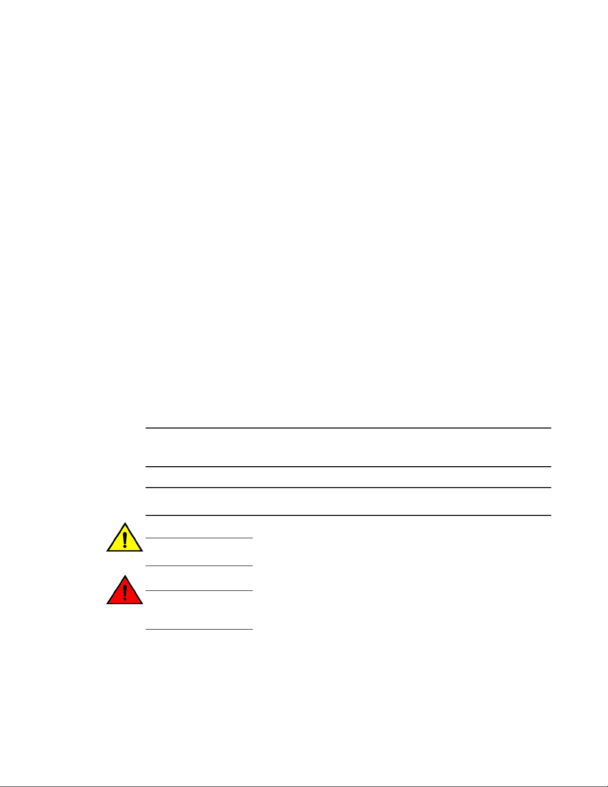
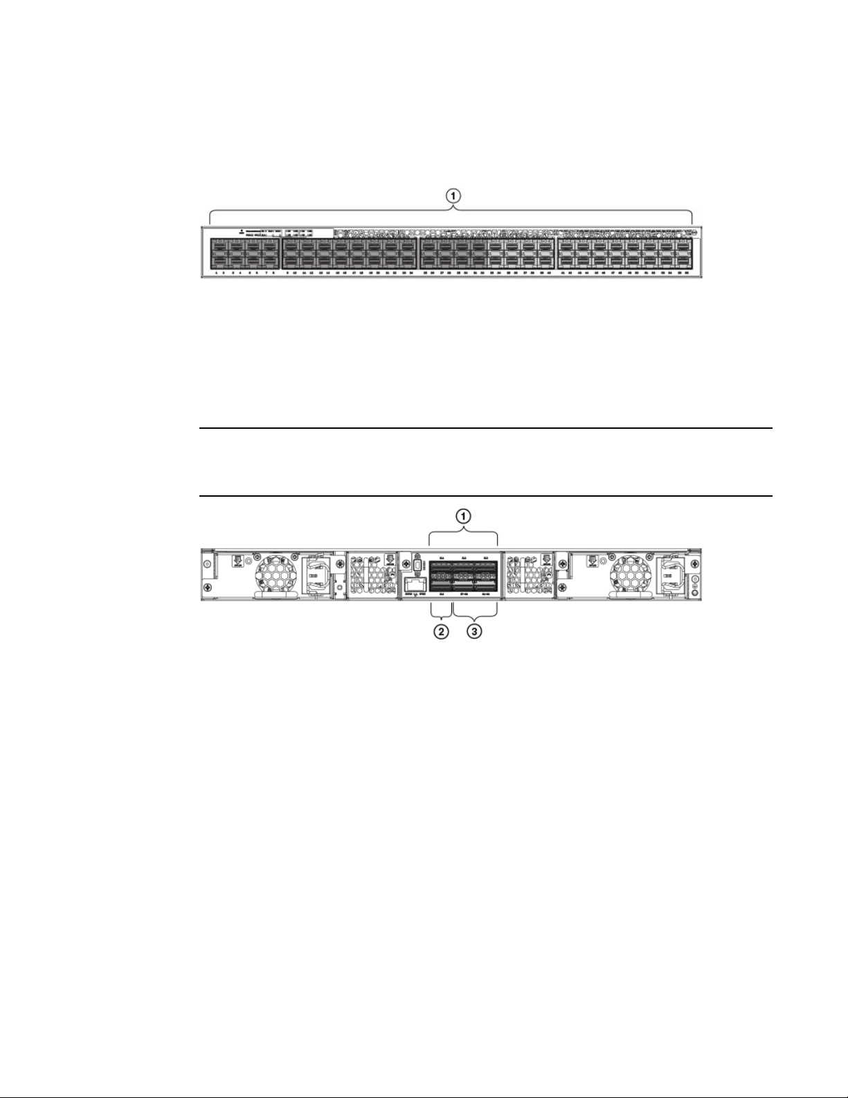
Views of the Brocade ICX 6650 switch
Push button reset
1
2 PSU1 and PSU2 status LEDs
3 DIAG and MS status LEDs
4 40 GbE QSFP rear port status/activity
LEDs
5 10 GbE QSFP-to-SFP breakout port
status/activity LED
6 Air intake/exhaust
7 Ports 1/1 through 1/32
8 Ports 1/33 through 1/40
9 Ports 1/41 through 1/48
10 Ports 1/49 through 1/56
FIGURE 1 Front view of the Brocade ICX 6650
14 Brocade ICX 6650 Hardware Installation Guide
53-1003083-01
Page 17
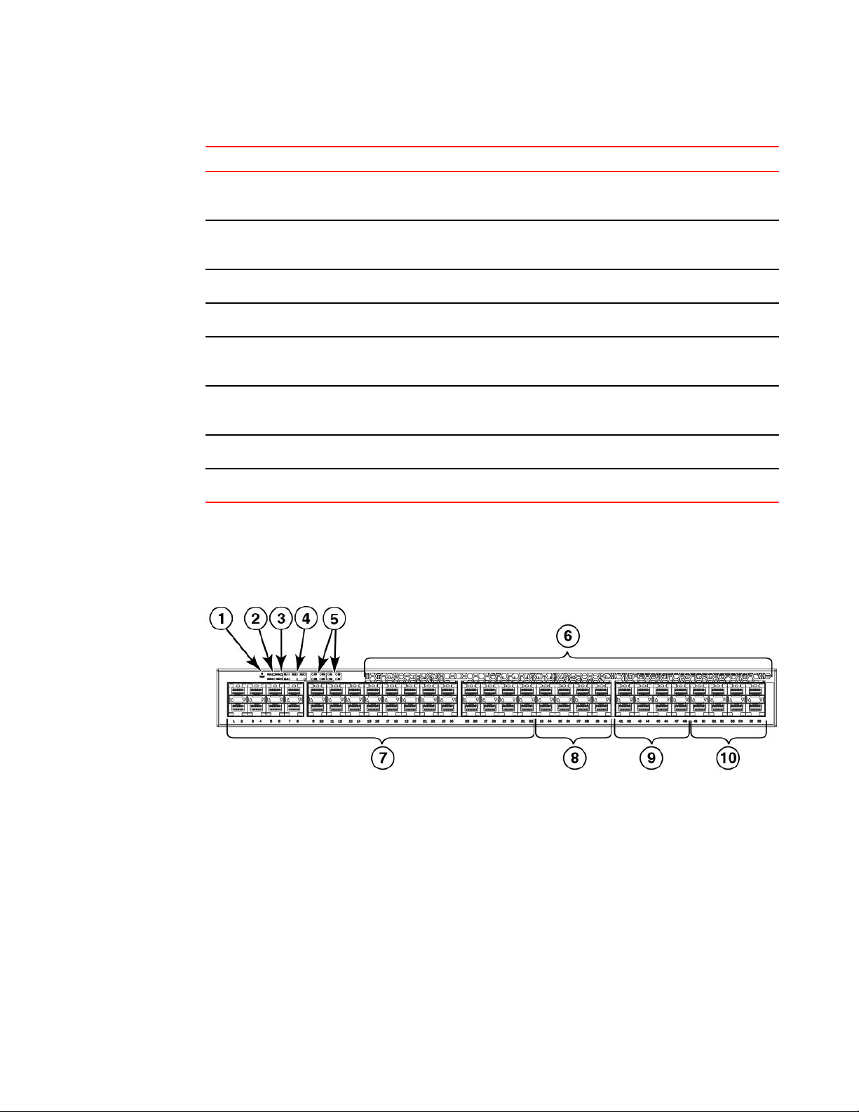
Ports on Demand licensing
1 Fan unit
2 Mini-USB serial console port
3 Ports 2/1 through 2/2
4 Port 2/3
5 Fan unit
FIGURE 2 Rear view of the Brocade ICX 6650
Ports on Demand licensing
The Brocade ICX 6650 features Ports on Demand licensing. With Ports on Demand licensing, software
features do not require licenses and you can add port licenses as needed.
A fully populated device supports 56 front-panel, dual-speed 1/10 GbE SFP+ ports, 4 rear-panel 40
GbE QSFP+ ports, and 2 rear-panel 4x10 GbE QSFP+ breakout ports.
You can purchase and install Ports on Demand licenses in blocks of eight dual-speed 1/10 GbE SFP+
on the front-panel ports. These ports are grouped sequentially, enabling ports 33 through 40, 41
through 48, and 49 through 56. To enable the additional front-panel ports, you must purchase and
install an ICX6650-8P10G-LIC-POD license.
6 Power supply
7 Ethernet management port
8 Port 2/4
9 Ports 3/1 through 3/8
10 Power supply
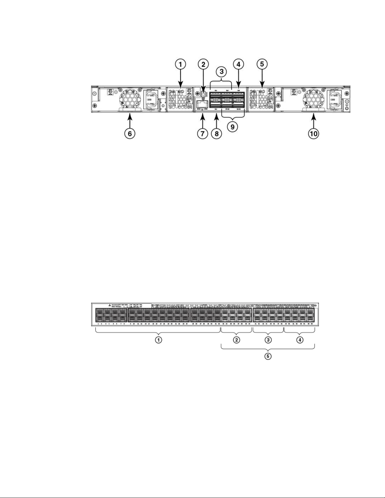
Base (32x10 GbE)
1
2 8x10 GbE (33-40)
3 8x10 GbE (41-48)
4 8x10 GbE (49-56)
5 Blocks of 8x10 GbE SFP+ ports
FIGURE 3 Brocade ICX 6650 front-panel ports
You can purchase and install up to three ICX6650-2P40G-LIC-POD licenses to enable pairs of 40 GbE
ports or 4x10 GbE breakout ports on the rear panel. An ICX6650-2P40G-LIC-POD license can be
applied to any of the following pairs of 40 GbE rear-panel ports or 4x10 GbE breakout ports:
Brocade ICX 6650 Hardware Installation Guide 15
53-1003083-01
Page 18
Brocade ICX 6650 slot and Ethernet port numbering
• 2/1 and 2/2 40 GbE rear-panel ports
• 2/3 and 2/4 40 GbE rear-panel ports
• 3/1-4 and 3/5-8 4x10 GbE rear-panel breakout ports
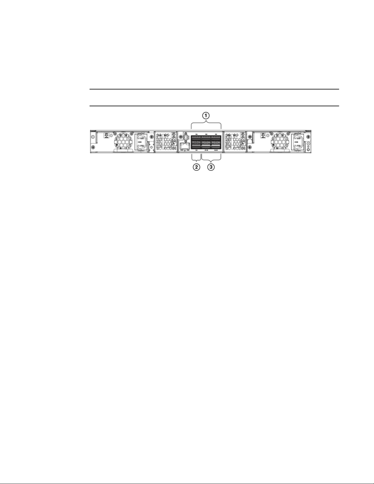
NOTE
You can add an ICX6650-2P40G-LIC-POD license to any configuration.
1 2/1-2: Any pair of QSFP+ ports—2x40
GbE ports (2/1-2, 2/3-4), 2 4x10 GbE
ports (3/1-4,3/5-8)
2 2/4
3 3/1-8: 4x10 GbE breakout ports (3/1-4,
3/5-8)
FIGURE 4 Brocade ICX 6650 rear-panel ports
The breakout ports support one of the following options:
• Direct-attached QSPF+ to 4 SFP+ copper breakout cables (Part number 40G-QSFP-4SFP-C-/
0101/0301/0501)
• Breakout-capable SR4 QSPF+ optical transceiver (Part number 40G-QSFP-SR4-INT)
No trial licenses are available with Ports on Demand licensing.
Brocade ICX 6650 slot and Ethernet port numbering
Many CLI commands require users to enter port numbers as part of the command syntax, and many
show command outputs display port numbers. The port numbers are entered and displayed in stack-
unit/slot number/port number format. In all Brocade ICX 6650 inputs and outputs, the stack-unit
number is always 1.
16 Brocade ICX 6650 Hardware Installation Guide
53-1003083-01
Page 19
Supported transceivers and cables
The Brocade ICX 6650 contains the following slots and Ethernet ports:
• Slot 1 is located on the front of the Brocade ICX 6650 switch and contains ports 1 through 56,
which are 1/10 GbE SFP+ ports. Refer to the following figure.
1 Slot 1
FIGURE 5 Brocade ICX 6650 front-panel ports
• Slot 2 is located on the rear of the Brocade ICX 6650 switch and contains ports 1 through 3 on the
top row and port 4 on the bottom row. These ports are 40 GbE QSFP+ ports. Refer to the following
figure.
NOTE
The QSFP+ 40GbE LR4 optical transceiver is supported in ports 1 and 2 only. When the module is
inserted into a stack-unit/slot number/port number combination that is not 1/2/1 or 1/2/2, the following
error message displays: “QSFP LR-4 optics not supported on port port-number.”
Slot 2
1
2 Slot 2
3 Slot 3
FIGURE 6 Brocade ICX 6650 rear-panel ports
• Slot 3 is located on the rear of the Brocade ICX 6650 switch and contains ports 1 through 8. These
ports are 4x10 GbE breakout ports and require the use of a breakout cable. Refer to the previous
figure.
Supported transceivers and cables
The Brocade ICX 6650 supports the following transceivers and cables:
• 1 GbE
Brocade ICX 6650 Hardware Installation Guide 17
53-1003083-01
Page 20

Breakout cables
‐ SX
‐ LX
‐ Copper
• 10 GbE
‐ SFP+: USR, Short Reach, Long Reach
‐ Active twinaxial copper (1 meter, 3 meter, and 5 meter)
‐ 10 GbE ER SFP+
• 40 GbE
‐ Standard 40 GbE (SR4) transceiver without breakout
‐ 40 GbE (SR4) QSFP+ transceiver with breakout to 4x10 GbE up to 100 meters on OM3
fiber
‐ 40 GbE direct attach (DAC) copper breakout (1 meter, 3 meter, and 5 meter)
‐ 40 GbE QSFP to QSFP active twinaxial (1 meter, 3 meter, and 5 meter)
‐ 40 GbE (LR4) QSFP+ transceiver up to 10 km
NOTE
Non-branded active twinaxial cables can be used, but Brocade does not support them.
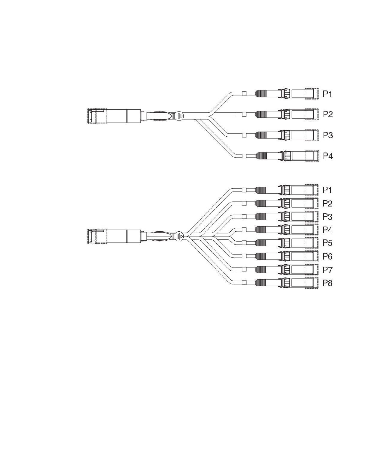
Breakout cables
The rear panel of the Brocade ICX 6650 contains two 4x10 GbE ports which support the following
cables:
18 Brocade ICX 6650 Hardware Installation Guide
53-1003083-01
Page 21
Brocade ICX 6650 Overview
• QSFP+ to 4 SFP+ (4x10 GbE) direct-attach copper breakout cables
• QSFP+ (MTP 1x8 or 1x12) optical breakout cables
FIGURE 7 QSFP+ to 4 SFP+ (4x10 GbE) direct-attach copper breakout cable
FIGURE 8 QSFP+ (MTP 1x8 or 1x12) optical breakout cable
Brocade ICX 6650 Hardware Installation Guide 19
53-1003083-01
Page 22

Breakout cables
20 Brocade ICX 6650 Hardware Installation Guide
53-1003083-01
Page 23

Installing the Brocade ICX 6650
● Unpacking the device......................................................................................................21
● Installation and safety considerations............................................................................. 22
● Installation tasks..............................................................................................................24
● Installation precautions................................................................................................... 24
● Installing the device in a rack or cabinet......................................................................... 26
● Attaching a PC or terminal.............................................................................................. 32
● Powering on the system..................................................................................................32
● Power supplies................................................................................................................33
● Installing an SFP+ transceiver........................................................................................ 40
Unpacking the device
The Brocade ICX 6650 ships with all of the items listed below. Verify the contents of your shipping
container. If any items are missing, contact the place of purchase.
Package contents (ICX6650-32-E-ADV, ICX6650-48-E-ADV, and ICX6650-56-E-ADV)
The following items are included in your shipping carton:
• A Brocade ICX 6650 device
• One accessory kit, containing the following items:
‐ Two power cords
‐ One RJ-45 to DB9F adapter
‐ One RJ-45 crossover cable
‐ One mini-USB (M)-DB9(F) cable
‐ Two mounting ears and screws
‐ Grounding terminal screw
Package contents (ICX6650-32-ADV)
Package contents (ICX6650-32-ADV)
The following items are included in your shipping carton:
• A Brocade ICX 6650 device
• One accessory kit, containing the following items:
‐ One RJ-45 to DB9F adapter
‐ One RJ-45 crossover cable
‐ One mini-USB (M)-DB9(F) cable
Brocade ICX 6650 Hardware Installation Guide
53-1003083-01
21
Page 24

Installation and safety considerations
‐ Two mounting ears and screws
‐ Grounding terminal screw
• Installed filler panels for the right power supply unit (PSU1) slot and left fan slot.
CAUTION
The filler panels must be in place if operating the switch with only one power supply and fan.
Installation and safety considerations
You can install the Brocade ICX 6650 in the following ways:
• As a standalone unit on a flat surface.
• In an EIA cabinet using a fixed-rail rack mount kit. The optional fixed-rail rack mount kit can be
ordered from your switch retailer. Both the 24"-28" rack depth kit and the 28"-32" rack depth kit
will work with the Brocade ICX 6650.
• In a 2-post Telco rack using a flush mount rack kit. The optional flush mount rack kit for switches
can be ordered from your switch retailer.
• In a 2-post Telco rack using a mid-mount rack kit. The optional mid-mount rack kit for switches
can be ordered from your switch retailer.
Electrical considerations
To install and operate the switch successfully, ensure compliance with the following requirements:
• The primary outlet is correctly wired, protected by a circuit breaker, and grounded in accordance
with local electrical codes.
• The supply circuit, line fusing, and wire size are adequate, as specified by the electrical rating on
the switch nameplate.
• The power supply standards are met.
Environmental considerations
For successful installation and operation of the switch, ensure that the following environmental
requirements are met:
• Because the Brocade ICX 6650 can be ordered with fans that move air either front to back or
back to front, be sure to orient your switch with the airflow pattern of any other devices in the rack.
All equipment in the rack should force air in the same direction to avoid intake of exhaust air.
• The ambient air temperature does not exceed 40° C (104° F) while the switch is operating.
• Some combinations of intake and exhaust airflows may not be compatible with your environment.
Consult your fan and power supply module FRU kit to determine the correct configuration.
Location considerations
Before installing the device, plan its location and orientation relative to other devices and equipment.
Devices can be mounted in a standard 19-inch equipment rack or on a flat surface.
The site should meet the following requirements:
22 Brocade ICX 6650 Hardware Installation Guide
53-1003083-01
Page 25

Cabinet considerations
• Maintain the operating environment as specified in Environmental considerations on page 22.
• Allow a minimum of 3 in. of space between the front and the back of the device and walls or other
obstructions for proper airflow.
• Allow at least 3 in. of space at the front and back of the device for the twisted-pair, fiber-optic, and
power cabling.
• Be accessible for installing, cabling, and maintaining the devices.
• Allow the status LEDs to be clearly visible.
• Allow for twisted-pair cables to be routed away from power lines, fluorescent lighting fixtures, and
other sources of electrical interference, such as radios and transmitters.
• Allow for the unit to be connected to a separate grounded power outlet that provides 100 to 240
VAC, 50 to 60 Hz, is within 2 m (6.6 ft) of each device, and is powered from an independent circuit
breaker. As with any equipment, a filter or surge suppressor is recommended.
Cabinet considerations
For successful installation and operation of the switch in a cabinet, ensure the following cabinet
requirements are met:
• The cabinet must be a standard EIA cabinet.
• The equipment in the cabinet is grounded through a reliable branch circuit connection and
maintains ground at all times. Do not rely on a secondary connection to a branch circuit, such as a
power strip.
• Airflow and temperature requirements are met on an ongoing basis, particularly if the switch is
installed in a closed or multicabinet assembly.
• The additional weight of the switch does not exceed the cabinet’s weight limits or unbalance the
cabinet in any way.
• The cabinet is secured to ensure stability in case of unexpected movement, such as an
earthquake.
Recommendations for cable management
Cables can be organized and managed in a variety of ways; for example, use cable channels on the
sides of the cabinet or patch panels to reduce the potential for tangling the cables. The following list
provides some recommendations for cable management:
CAUTION
Before plugging a cable to any port, be sure to discharge any static charge stored on the cable
by touching the electrical contacts to ground surface.
ATTENTION
You should not use tie wraps with optical cables because they are easily overtightened and can
damage the optic fibers. Velcro-like wraps are recommended.
• Plan for the rack space required for cable management before installing the switch.
• Leave at least 1 m (3.28 ft) of slack for each port cable. This provides room to remove and replace
the switch, allows for inadvertent movement of the rack, and helps prevent the cables from being
bent to less than the minimum bend radius.
• For easier maintenance, label the cables and record the devices to which they are connected.
• Keep LEDs visible by routing port cables and other cables away from the LEDs.
Brocade ICX 6650 Hardware Installation Guide 23
53-1003083-01
Page 26

Installation tasks
Installation tasks
Perform the following steps to install your device. Details for each of these steps are provided on the
pages indicated.
Task number Task Where to find more information
Installation tasks TABLE 4
1 Ensure that the physical environment that will host the device
has the proper cabling and ventilation.
2 If customizing the ICX6650-32-ADV baseline chassis:
1. Install at least one power supply unit.
2. Install at least one fan.
3. Obtain and install a PoD license, as described in the
FastIron Ethernet Switch Administration Guide.
3 Install the device in an equipment rack. Installing the device in a rack or
4 Attach a terminal or PC to the device. This will enable you to
configure the device through the command line interface
(CLI).
5 Plug the device into a nearby power source that adheres to
the regulatory requirements outlined in this manual.
6 Assign a password for additional access security. No default
password is assigned to the CLI.
7 Before attaching equipment to the device, you must configure
an interface IP address to the subnet on which the device will
be located. Initial IP address configuration is performed using
the CLI with a direct serial connection. Subsequent IP
address configuration can be performed using the Web
management interface.
Environmental considerations on
page 22
Installing and replacing a power
supply unit on page 33
Installing or replacing the fan
assembly on page 66
cabinet on page 26
Attaching a PC or terminal on
page 32
Powering on the system on page
32
Assigning permanent passwords
on page 43
Configuring IP addresses on page
44
9 Test IP connectivity to other devices by pinging them and
tracing routes.
10 Continue configuring the device using the CLI or the Web
management interface.
11 Secure access to the device. FastIron Ethernet Switch
Testing connectivity on page 49
FastIron Ethernet Switch
Administration Guide
Administration Guide
Installation precautions
Follow all precautions when installing a device.
24 Brocade ICX 6650 Hardware Installation Guide
53-1003083-01
Page 27
General precautions
General precautions
CAUTION
All fiber-optic interfaces use Class 1 lasers.
CAUTION
Do not install the device in an environment where the operating ambient temperature might
exceed 40° C (104° F).
CAUTION
Make sure the airflow around the front and sides of the device is not restricted.
CAUTION
Never leave tools inside the device.
Lifting precautions
CAUTION
Make sure the rack or cabinet housing the device is adequately secured to prevent it from
becoming unstable or falling over.
Power precautions
CAUTION
Use a separate branch circuit for each AC power cord, which provides redundancy in case one
of the circuits fails.
CAUTION
To avoid high voltage shock, do not open the device while the power is on.
Brocade ICX 6650 Hardware Installation Guide 25
53-1003083-01
Page 28
Installing the device in a rack or cabinet
CAUTION
Ensure that the device does not overload the power circuits, wiring, and over-current
protection. To determine the possibility of overloading the supply circuits, add the ampere
(amp) ratings of all devices installed on the same circuit as the device. Compare this total with
the rating limit for the circuit. The maximum ampere ratings are usually printed on the devices
near the input power connectors.
CAUTION
Disconnect the power cord from all power sources to completely remove power from the
device.
CAUTION
Before plugging a cable to any port, be sure to discharge any static charge stored on the cable
by touching the electrical contacts to ground surface.
CAUTION
If the installation requires a different power cord than the one supplied with the device, make
sure you use a power cord displaying the mark of the safety agency that defines the
regulations for power cords in your country. The mark is your assurance that the power cord
can be used safely with the device.
Installing the device in a rack or cabinet
CAUTION
Make sure the rack or cabinet housing the device is adequately secured to prevent it from
becoming unstable or falling over.
NOTE
You need a #2 Phillips screwdriver for installation.
Before mounting the switch in a rack, pay particular attention to the following factors:
• Temperature: Because the temperature within a rack assembly may be higher than the ambient
room temperature, check that the rack-environment temperature is within the specified operating
temperature range.
• Mechanical loading: Do not place any equipment on top of a rack-mounted unit.
• Circuit overloading: Be sure that the supply circuit to the rack assembly is not overloaded.
• Grounding: Rack-mounted equipment should be properly grounded. Particular attention should be
given to supply connections other than direct connections to the mains.
26 Brocade ICX 6650 Hardware Installation Guide
53-1003083-01
Page 29

2-post rack mount installation
2-post rack mount installation
NOTE
Use the following procedure when installing the Brocade ICX 6650 in a 2-post rack. For 4-post racks,
follow the procedures in 4-post rack mount installation on page 29.
Use the following steps to mount the Brocade ICX 6650 in a 2-post rack.
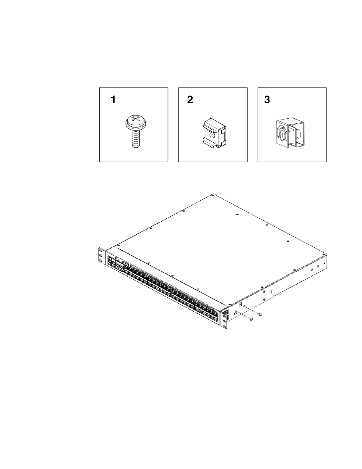
1. Remove the rack mount kit from the shipping carton. The kit contains the following:
• Two L-shaped mounting brackets.
• Sixteen 8-32 x 5/16 in., panhead Phillips screws with patchlocks.
• Four 10-32 x 5/8 in., panhead Phillips screws (torque to 25 in-lb, 29 cm-kg). Refer to item 1 in
the following figure.
Brocade ICX 6650 Hardware Installation Guide 27
53-1003083-01
Page 30
Installing the Brocade ICX 6650
• Eight 32-10 retainer nuts (for square-hole rack rails). Refer to item 2 in the following figure.
• Eight 32-10 retainer nuts (for round-hole rack rails). Refer to item 3 in the following figure.
FIGURE 9 2-post screws and retainer nuts
2. Attach the mounting brackets to the sides of the device using the 8-32 x 5/16 in. screws.
FIGURE 10 Attaching the mounting brackets for aBrocade ICX 6650
Position the device in the cabinet, providing temporary support under the switch until the rail kit is
3.
secured to the cabinet.
28 Brocade ICX 6650 Hardware Installation Guide
53-1003083-01
Page 31

4-post rack mount installation
4. Attach the front right bracket to the rail rack using two 10-32 x 5/8 in. screws and the appropriate
round-hole or square-hole retainer nuts. Refer to the following figure.
FIGURE 11 Installing the Brocade ICX 6650 in a 2-post rack
5. Repeat Step 3 to attach the left front bracket to the left front rack rail and tighten all 10-32 x 5/8 in.
screws to a torque of 25 in-lb (29 cm-kg).
Proceed to Attaching a PC or terminal on page 32.
4-post rack mount installation
Kits for 4-post rack mounting are not included in the shipping carton and must be ordered separately.
NOTE
Use the following procedure when installing the Brocade ICX 6650 in a 4-post rack cabinet. For 2-post
cabinets, follow the procedures in 2-post rack mount installation on page 27.
Use the following steps to mount the Brocade ICX 6650 in a 4-post rack.
1. Remove the rack mount kit from the shipping carton. The kit contains the following:
• Two L-shaped mounting brackets.
• Four rack mount rails: two for side attach and two for rear attach racks.
• Thirty-two 8-32 x 5/16 in., panhead Phillips screws with patchlocks.
• Eight 10-32 x 5/8 in., panhead Phillips screws (torque to 25 in-lb, 29 cm-kg). Refer to item 1 in
the following figure.
Brocade ICX 6650 Hardware Installation Guide 29
53-1003083-01
Page 32

Installing the Brocade ICX 6650
• Eight 32-10 retainer nuts (for square-hole rack rails). Refer to item 2 in the following figure.
• Eight 32-10 retainer nuts (for round-hole rack rails). Refer to item 3 in the following figure.
FIGURE 12 4-post screws and retainer nuts
CAUTION
Do not use the hardware supplied in a 2-post rack mounting kit to mount a Brocade ICX
6650 in a 4-post rack. Mounting the in a 4-post rack requires additional hardware to prevent
drooping from possible flexing and distortion of the 4-post rack when a device is not
properly installed.
2. Attach the mounting brackets to the sides of the device as illustrated in 2-post rack mount
installation on page 27 using the 8-32 x 5/16 in. screws.
3. Attach the appropriate rails: either side attach or rear attach as determined by the type of rack in
which you are installing the device.
30 Brocade ICX 6650 Hardware Installation Guide
53-1003083-01
Page 33

Installing the Brocade ICX 6650
The following figures show exploded views of the optional 4-post rack mount kit.
FIGURE 13 Optional 4-post rack mount kit, rear attachment
FIGURE 14 Optional 4-post rack mount kit, side attachment
4. Position the switch in the cabinet, providing temporary support under the switch until the rail kit is
secured to the cabinet.
5. Attach the front right bracket to the rail rack using two 10-32 x 5/8 in. screws and the appropriate
round-hole or square-hole retainer nuts.
6. Repeat step 5 to attach the left front bracket to the left front rack rail and tighten all 10-32 x 5/8 in.
screws to a torque of 25 in-lb (29 cm-kg).
7. Attach the rear right bracket to the rail rack using two 10-32 x 5/8 in. screws and the appropriate
round-hole or square-hole retainer nuts.
8. Repeat step 7 to attach the rear left bracket to the rail rack and tighten all 10-32 x 5/8 in. screws to
a torque of 25 in-lb (29 cm-kg).
Proceed to Attaching a PC or terminal on page 32.
Brocade ICX 6650 Hardware Installation Guide 31
53-1003083-01
Page 34

Attaching a PC or terminal
Attaching a PC or terminal
To assign an IP address, you must have access to the command line interface (CLI). The CLI is a textbased interface that can be accessed through a direct serial connection to the device and through
Telnet connections. The CLI is described in detail in the FastIron Ethernet Switch Administration
Guide.
Access the CLI by connecting to the console port. After you assign an IP address, you can access the
system through Telnet, the Web management interface, or Brocade Network Advisor.
Use the following steps to attach a management station to the console port.
1. Connect a PC or terminal to the console management port on the rear of the Brocade ICX 6650
using the mini-USB serial console port cable (Part number 50-1000059-01.
For port pinout information for the mini-USB serial console port, refer to Pinouts and signaling on
page 74.
NOTE
You must run a terminal emulation program on the PC.
2. Launch the terminal emulation program and set the following session parameters:
• Baud: 9600 bps
• Data bits: 8
• Parity: None
• Stop bits: 1
• Flow control: None
The console serial communication port serves as a connection point for management by a PC.
Powering on the system
After you complete the physical installation, you can power on the system.
1. Remove the power cable from the shipping package container.
2. Attach the AC power cable to the AC connector on the rear panel.
3. Insert the power cable plug into a 100V-240V outlet.
NOTE
To turn the system off, simply unplug the power cable or cables.
NOTE
The socket should be installed near the equipment and should be easily accessible.
32 Brocade ICX 6650 Hardware Installation Guide
53-1003083-01
Page 35

Power supplies
Each Brocade ICX 6650 comes with two alternating-current (AC) power supplies. The Brocade ICX
6650 device also supports direct-current (DC) power supplies. The Brocade ICX 6650 is capable of
running on one power supply and one fan. The second set provide redundancy.
If the second power supply and fan slots are unused, you must cover them with filler panels.
CAUTION
When running two power supplies, they must be of the same type: either two alternating-current
(AC) power supplies or two direct-current (DC) power supplies. AC and DC units cannot be
mixed in a device.
Installing and replacing a power supply unit
When installing or replacing a power supply unit, keep in mind the following:
• Power supplies can be swapped in or out while the device is running. The remaining power supply
• The airflow direction of the power supply must match that of the installed fan tray. All must be either
Power supplies
provides enough power for the device.
exhaust or intake.
CAUTION
Power supplies are hot-swappable. However, they should be inserted or removed without a
power cord being connected to a power source to avoid damage.
CAUTION
For Brocade ICX 6650 devices, be sure that the airflow direction of the power supply unit
matches that of the installed fan tray. The power supplies and fan trays are clearly labeled with
either a green arrow with an "E", or an orange arrow with an "I."
Installing an AC power supply
NOTE
You need a #2 Phillips screwdriver and a flat-head screwdriver for installation.
Brocade ICX 6650 Hardware Installation Guide 33
53-1003083-01
Page 36

Installing the Brocade ICX 6650
Use the following steps to install an AC power supply in the switch.
FIGURE 15 Installing an AC power supply unit
1. If replacing a power supply, remove the previously installed power supply from the appropriate
slot by removing the two screws with a flat-head screwdriver.
2. If installing a new power supply into a slot covered with a filler panel:
a) Using a Phillips screwdriver, unscrew the screws on the filler panel.
b) Remove the filler panel.
3. Before opening the package that contains the power supply, touch the bag to the switch casing to
discharge any potential static electricity. Brocade recommends using an ESD wrist strap during
installation.
4. Remove the power supply from the anti-static shielded bag.
5. Holding the power supply level, guide it into the carrier rails on each side and gently push it all the
way into the slot, ensuring that it firmly engages with the connector.
6. When you are sure the power supply has properly engaged the connector, tighten the retainer
screws to secure the power supply in the slot.
When the device is powered on, the AC or DC LEDs on the power supply back panel should turn
green to confirm that the power supply is correctly installed and supplying power.
You can also verify correct installation by running the show chassis command, as shown in this
example:
ICX6650-64 Router#show chassis
The stack unit 1 chassis info:
Power supply 1 (AC - Regular) present, status ok
Model Number: 23-0000144-01
Serial Number: 028
Firmware Ver: A
Power supply 1 Fan Air Flow Direction: Front to Back
Power supply 2 not present
Fan 1 ok, speed (auto):