


Page 1

53-1003082-02
11 April 2014
Brocade ICX 6610
Stackable Switch
Hardware Installation Guide
Supporting FastIron Software Release 08.0.10
Page 2

©
2014, Brocade Communications Systems, Inc. All Rights Reserved.
Brocade, the B-wing symbol, Brocade Assurance, ADX, AnyIO, DCX, Fabric OS, FastIron, HyperEdge, ICX, MLX, MyBrocade, NetIron,
OpenScript, VCS, VDX, and Vyatta are registered trademarks, and The Effortless Network and the On-Demand Data Center are trademarks
of Brocade Communications Systems, Inc., in the United States and in other countries. Other brands and product names mentioned may be
trademarks of others.
Notice: This document is for informational purposes only and does not set forth any warranty, expressed or implied, concerning any
equipment, equipment feature, or service offered or to be offered by Brocade. Brocade reserves the right to make changes to this document
at any time, without notice, and assumes no responsibility for its use. This informational document describes features that may not be
currently available. Contact a Brocade sales office for information on feature and product availability. Export of technical data contained in
this document may require an export license from the United States government.
The authors and Brocade Communications Systems, Inc. assume no liability or responsibility to any person or entity with respect to the
accuracy of this document or any loss, cost, liability, or damages arising from the information contained herein or the computer programs that
accompany it.
The product described by this document may contain open source software covered by the GNU General Public License or other open
source license agreements. To find out which open source software is included in Brocade products, view the licensing terms applicable to
the open source software, and obtain a copy of the programming source code, please visit http://www.brocade.com/support/oscd.
Page 3

Contents
Preface.....................................................................................................................................5
Document conventions......................................................................................5
Text formatting conventions.................................................................. 5
Command syntax conventions.............................................................. 5
Notes, cautions, and warnings.............................................................. 6
Brocade resources............................................................................................ 7
Getting technical help........................................................................................7
Document feedback.......................................................................................... 8
About This Document................................................................................................................ 9
Introduction....................................................................................................... 9
Supported software............................................................................... 9
What’s new in this document ........................................................................... 9
ICX 6610 Overview..................................................................................................................11
Hardware features...........................................................................................11
Management interfaces...................................................................................12
Console management interface ......................................................... 13
Out-of-band management interface.................................................... 13
Reset button........................................................................................13
Network interfaces for ICX 6610devices......................................................... 13
Slot locations.......................................................................................14
Slot designations.................................................................................15
10/100/1000 BASE-T ports................................................................. 15
SFP interfaces.....................................................................................15
40-Gbps QSFP interface stacking ports..............................................16
Specifying a port address................................................................................16
Specifying a data port......................................................................... 16
Specifying a stacking port................................................................... 16
Specifying a management port........................................................... 17
Port, system, and power status LEDs............................................................. 17
Fan trays......................................................................................................... 20
Power supplies................................................................................................20
PoE and PoE+ power..........................................................................21
Installing the ICX 6610 Switch................................................................................................ 23
Unpacking the device......................................................................................23
Installation tasks..............................................................................................24
Installation precautions................................................................................... 25
Preparing the installation site.......................................................................... 26
Brocade ICX 6610 Stackable Switch Hardware Installation Guide
53-1003082-02
Package contents................................................................................23
General requirements......................................................................... 23
General precautions............................................................................25
Lifting precautions............................................................................... 25
Power precautions.............................................................................. 25
Cabling infrastructure.......................................................................... 26
Installation location..............................................................................26
1
Page 4

Installing the device.......................................................................................27
Desktop installation...........................................................................28
Rack mount installation.....................................................................28
2-Post rack mount installation...........................................................29
4-Post rack mount installation...........................................................33
Connecting devices in a traditional stack......................................................36
Stacking ports and trunks..................................................................36
Stacking configuration requirements.................................................37
Stacking cables.................................................................................37
Stack size..........................................................................................38
Stacking topologies...........................................................................38
Connecting devices in a mixed stack............................................................41
ICX 6610 stacking ports and trunks.................................................. 41
ICX 6450 stacking ports and trunks.................................................. 44
Stacking configuration requirements.................................................45
Stacking cables.................................................................................45
Stack size..........................................................................................45
Stacking topologies...........................................................................46
Connecting ICX 6610 devices in the backbone................................ 50
Connecting a peripheral device to an ICX 6610 and to another
peripheral device......................................................................... 50
Extended distance stacking.............................................................. 51
Attaching a PC or terminal............................................................................ 51
Powering on the system................................................................................52
Power supplies for the Brocade ICX 6610.................................................... 52
Installing and replacing a power supply unit..................................... 53
Installing an AC power supply...........................................................53
Installing a DC power supply.............................................................55
DC-DC power source cautions..........................................................58
Installing or replacing fan trays..................................................................... 59
Checking Network Devices and Testing Connectivity...............................................................61
Assigning permanent passwords.................................................................. 61
Setting passwords.............................................................................62
Recovering from a lost password......................................................62
Configuring IP addresses..............................................................................63
Devices running Layer 2 software.....................................................63
Devices running Layer 3 software.....................................................64
Connecting network devices......................................................................... 67
Connectors........................................................................................67
Cable specifications.......................................................................... 67
Connecting to Ethernet or fast Ethernet hubs...................................67
Connecting to workstations, servers, or routers................................68
Connecting a network device to a fiber port......................................69
Testing connectivity.......................................................................................72
Pinging an IP address.......................................................................72
Observing LEDs................................................................................72
Tracing a route..................................................................................73
Troubleshooting network connections.......................................................... 74
Digital optical monitoring...................................................................74
Managing the ICX 6610 Hardware.........................................................................................75
Managing temperature settings.................................................................... 75
Using the temperature sensor...........................................................75
Displaying the temperature............................................................... 75
Displaying Syslog messages for temperature...................................76
2
Brocade ICX 6610 Stackable Switch Hardware Installation Guide
53-1003082-02
Page 5

Changing the temperature warning level ........................................... 76
Changing the temperature poll time.................................................... 78
Removing MAC address entries..................................................................... 78
Displaying ICX 6610 CPU usage.................................................................... 78
Hardware maintenance schedule....................................................................79
Replacing a copper or fiber optic module........................................................79
Removing a copper or fiber-optic module........................................... 79
Cabling a fiber optic module................................................................80
Cleaning the fiber optic connectors.....................................................80
Hardware Specifications......................................................................................................... 81
Hardware specifications.................................................................................. 81
Physical dimensions and weight......................................................... 81
Environmental considerations............................................................. 81
Cooling system and fans.....................................................................82
Pinouts and signalling......................................................................... 83
Cable specifications............................................................................ 84
Power cords........................................................................................ 86
AC power supply specifications.......................................................... 86
Power consumption specifications...................................................... 87
Troubleshooting ..................................................................................................................... 89
Diagnosing switch indicators...........................................................................89
Power and cooling problems...............................................................89
Installation........................................................................................... 89
In-band access....................................................................................90
Regulatory Statements............................................................................................................91
USA (FCC CFR 47 Part 15 Warning)..............................................................91
Industry Canada statement............................................................................. 91
Europe and Australia (CISPR 22 Class A Warning)....................................... 92
Germany (Noise Warning).............................................................................. 92
Japan (VCCI).................................................................................................. 92
Japan power cord............................................................................................92
Korea...............................................................................................................93
China...............................................................................................................94
Russia............................................................................................................. 95
BSMI statement (Taiwan)................................................................................95
Regulatory compliance....................................................................................95
Cautions and Danger Notices.................................................................................................. 97
Cautions.......................................................................................................... 97
Danger notices.............................................................................................. 101
Index.................................................................................................................................... 105
Brocade ICX 6610 Stackable Switch Hardware Installation Guide
53-1003082-02
3
Page 6

4 Brocade ICX 6610 Stackable Switch Hardware Installation Guide
53-1003082-02
Page 7

Preface
● Document conventions......................................................................................................5
● Brocade resources............................................................................................................ 7
● Getting technical help........................................................................................................7
● Document feedback.......................................................................................................... 8
Document conventions
The document conventions describe text formatting conventions, command syntax conventions, and
important notice formats used in Brocade technical documentation.
Text formatting conventions
Text formatting conventions such as boldface, italic, or Courier font may be used in the flow of the text
to highlight specific words or phrases.
Format
bold text
italic text
Courier font
Description
Identifies command names
Identifies keywords and operands
Identifies the names of user-manipulated GUI elements
Identifies text to enter at the GUI
Identifies emphasis
Identifies variables and modifiers
Identifies paths and Internet addresses
Identifies document titles
Identifies CLI output
Identifies command syntax examples
Command syntax conventions
Bold and italic text identify command syntax components. Delimiters and operators define groupings of
parameters and their logical relationships.
Convention
bold text Identifies command names, keywords, and command options.
italic text Identifies a variable.
Description
Brocade ICX 6610 Stackable Switch Hardware Installation Guide 5
53-1003082-02
Page 8

Notes, cautions, and warnings
Convention Description
value In Fibre Channel products, a fixed value provided as input to a command
option is printed in plain text, for example, --show WWN.
[ ]
{ x | y | z }
x | y
< >
...
\
Syntax components displayed within square brackets are optional.
Default responses to system prompts are enclosed in square brackets.
A choice of required parameters is enclosed in curly brackets separated by
vertical bars. You must select one of the options.
In Fibre Channel products, square brackets may be used instead for this
purpose.
A vertical bar separates mutually exclusive elements.
Nonprinting characters, for example, passwords, are enclosed in angle
brackets.
Repeat the previous element, for example, member[member...].
Indicates a “soft” line break in command examples. If a backslash separates
two lines of a command input, enter the entire command at the prompt without
the backslash.
Notes, cautions, and warnings
Notes, cautions, and warning statements may be used in this document. They are listed in the order of
increasing severity of potential hazards.
NOTE
A Note provides a tip, guidance, or advice, emphasizes important information, or provides a reference
to related information.
ATTENTION
An Attention statement indicates a stronger note, for example, to alert you when traffic might be
interrupted or the device might reboot.
CAUTION
A Caution statement alerts you to situations that can be potentially hazardous to you or cause
damage to hardware, firmware, software, or data.
DANGER
A Danger statement indicates conditions or situations that can be potentially lethal or
extremely hazardous to you. Safety labels are also attached directly to products to warn of
these conditions or situations.
6 Brocade ICX 6610 Stackable Switch Hardware Installation Guide
53-1003082-02
Page 9

Brocade resources
Visit the Brocade website to locate related documentation for your product and additional Brocade
resources.
You can download additional publications supporting your product at www.brocade.com.
• Adapter documentation is available on the Downloads and Documentation for Brocade Adapters
page. Select your platform and scroll down to the Documentation section.
• For all other products, select the Brocade Products tab to locate your product, then click the
Brocade product name or image to open the individual product page. The user manuals are
available in the resources module at the bottom of the page under the Documentation category.
To get up-to-the-minute information on Brocade products and resources, go to MyBrocade. You can
register at no cost to obtain a user ID and password.
Release notes are available on MyBrocade under Product Downloads.
White papers, online demonstrations, and data sheets are available through the Brocade website.
Brocade resources
Getting technical help
You can contact Brocade Support 24x7 online, by telephone, or by e-mail.
For product support information and the latest information on contacting the Technical Assistance
Center, go to http://www.brocade.com/services-support/index.html.
Use one of the following methods to contact the Brocade Technical Assistance Center.
Online Telephone E-mail
Preferred method of contact for nonurgent issues:
• My Cases through MyBrocade
• Software downloads and
licensing tools
• Knowledge Base
Required for Sev 1-Critical and Sev
2-High issues:
• Continental US:
1-800-752-8061
• Europe, Middle East, Africa,
and Asia Pacific: +800-AT
FIBREE (+800 28 34 27 33)
• For areas unable to access toll
free number: +1-408-333-6061
• Toll-free numbers are available
in many countries.
support@brocade.com
Please include:
• Problem summary
• Serial number
• Installation details
• Environment description
Brocade ICX 6610 Stackable Switch Hardware Installation Guide 7
53-1003082-02
Page 10

Document feedback
Document feedback
To send feedback and report errors in the documentation you can use the feedback form posted with
the document or you can e-mail the documentation team.
Quality is our first concern at Brocade and we have made every effort to ensure the accuracy and
completeness of this document. However, if you find an error or an omission, or you think that a topic
needs further development, we want to hear from you. You can provide feedback in two ways:
• Through the online feedback form in the HTML documents posted on www.brocade.com.
• By sending your feedback to documentation@brocade.com.
Provide the publication title, part number, and as much detail as possible, including the topic heading
and page number if applicable, as well as your suggestions for improvement.
8 Brocade ICX 6610 Stackable Switch Hardware Installation Guide
53-1003082-02
Page 11

About This Document
● Introduction....................................................................................................................... 9
● What’s new in this document ........................................................................................... 9
Introduction
This guide includes procedures for installing and maintaining the hardware. The hardware procedures
show how to install or assemble the various hardware components with the necessary precautions,
warnings, and regulatory statements. This guide also describes the required device specifications for
running the hardware.
Supported software
For information about the features supported on a hardware platform, refer to the appropriate
configuration guide.
What’s new in this document
There are no new features for FastIron software release 08.0.10.
Brocade ICX 6610 Stackable Switch Hardware Installation Guide
53-1003082-02
9
Page 12

What’s new in this document
10 Brocade ICX 6610 Stackable Switch Hardware Installation Guide
53-1003082-02
Page 13

ICX 6610 Overview
● Hardware features...........................................................................................................11
● Management interfaces...................................................................................................12
● Network interfaces for ICX 6610devices......................................................................... 13
● Specifying a port address................................................................................................16
● Port, system, and power status LEDs............................................................................. 17
● Fan trays......................................................................................................................... 20
● Power supplies................................................................................................................20
Hardware features
The following hardware platforms are described in this guide:
• ICX 6610-24F -- 24 100/1000 Mbps SFP fiber ports, eight 1/10 Gbps SFP ports, two 40 Gbps and
two 4x10 Gbps stacking ports
• ICX 6610-24 -- 24 10/100/1000 Mbps copper ports, eight 1/10 Gbps SFP ports, two 40 Gbps and
two 4x10 Gbps stacking ports
• ICX 6610-24P -- 24 10/100/1000 Mbps copper PoE ports, eight 1/10 Gbps SFP ports, two 40 Gbps
and two 4x10 Gbps stacking ports
• ICX 6610-48 -- 48 10/100/1000 Mbps copper ports, eight 1/10 Gbps SFP ports, two 40 Gbps and
two 4x10 Gbps stacking ports
• ICX 6610-48P -- 48 10/100/1000 Mbps PoE copper ports, eight 1/10 SFP Gbps ports, two 40 Gbps
and two 4x10 Gbps stacking ports
The following sections describe the physical characteristics of the ICX 6610 models. For more details
about physical dimensions, power supply specifications, and pinouts, refer to the Hardware
Specifications section.
Brocade ICX 6610 Stackable Switch Hardware Installation Guide
53-1003082-02
11
Page 14
Management interfaces
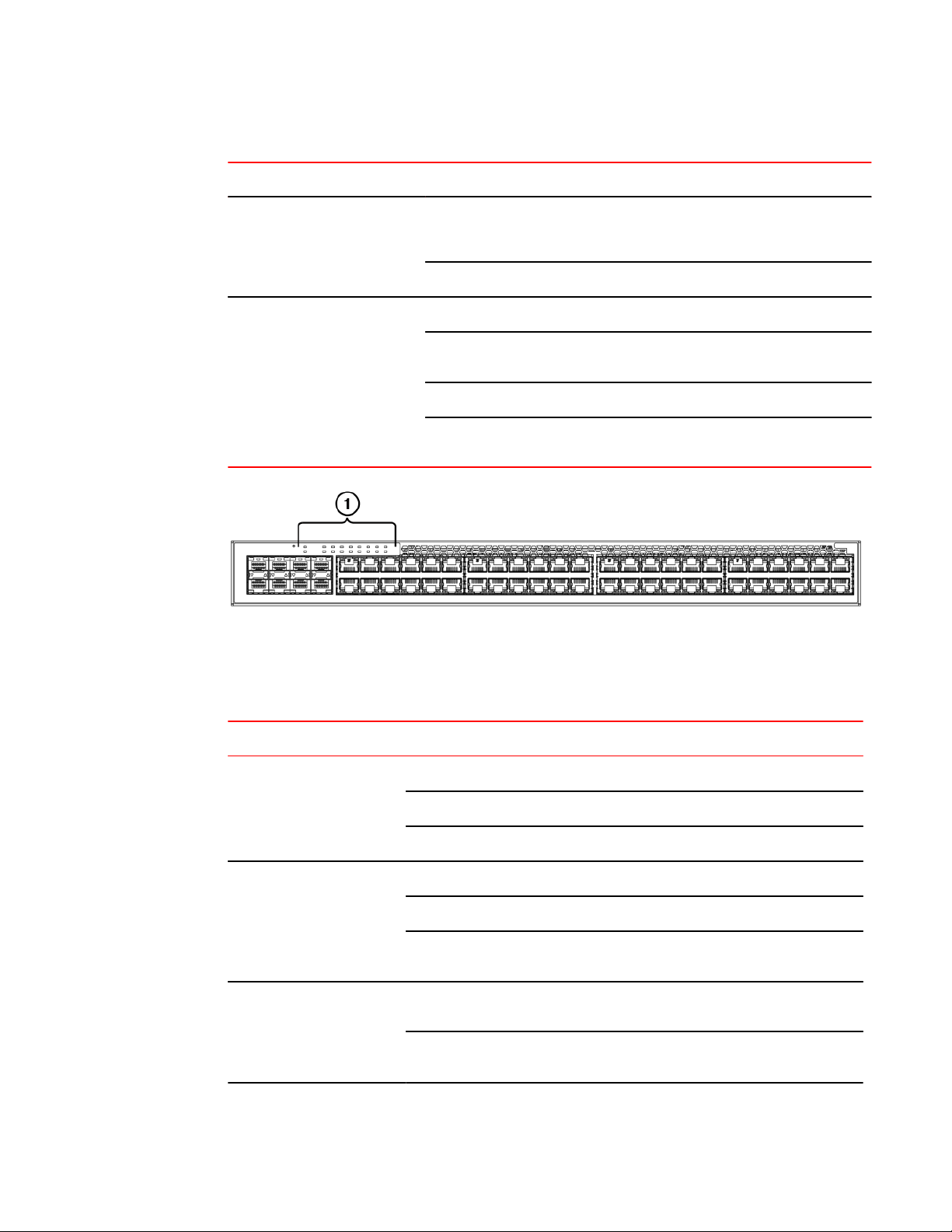
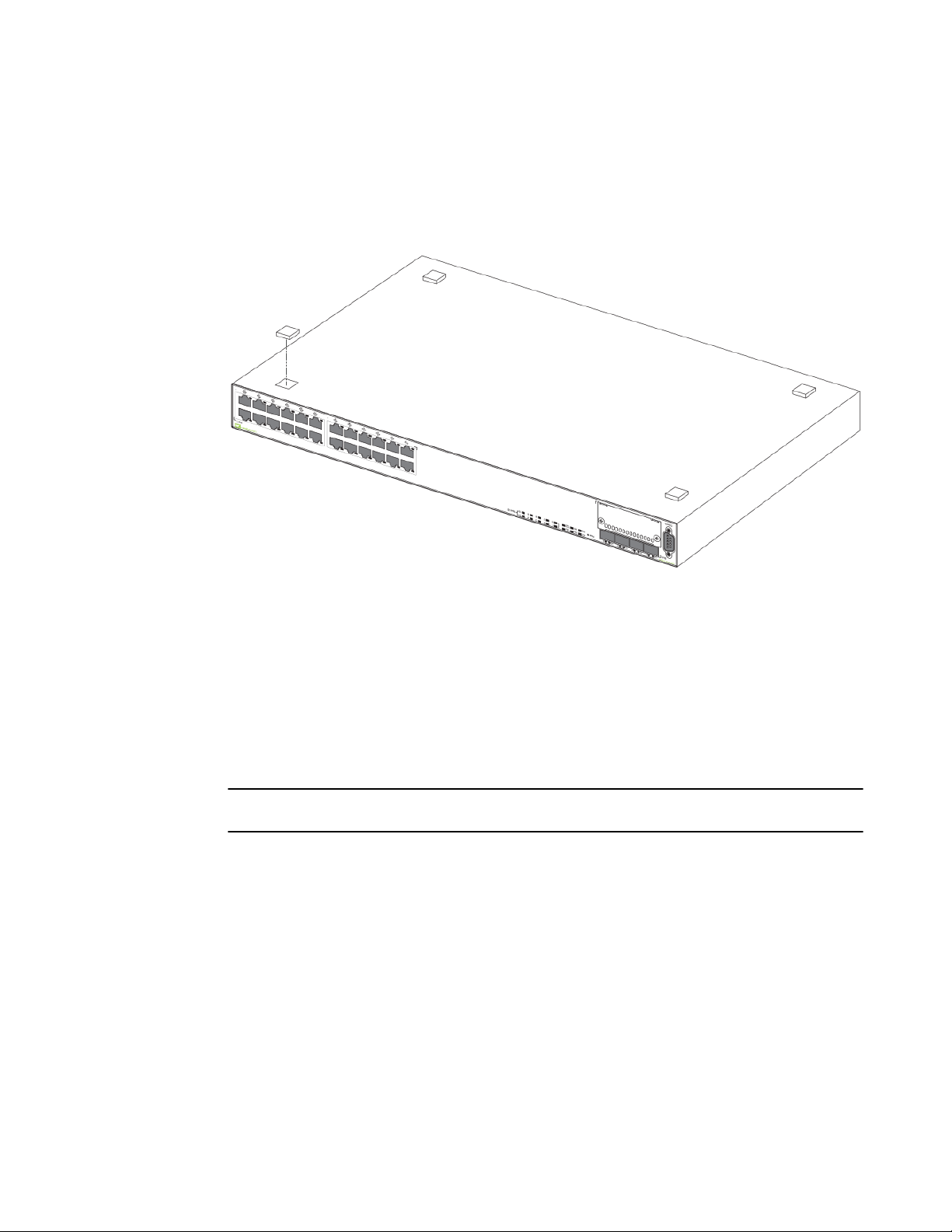
The following figures show the front and rear panels of the ICX 6610 models.
FIGURE 1 ICX 6610-24F front panel
FIGURE 2 ICX 6610-24 and ICX 6610-24P front panels
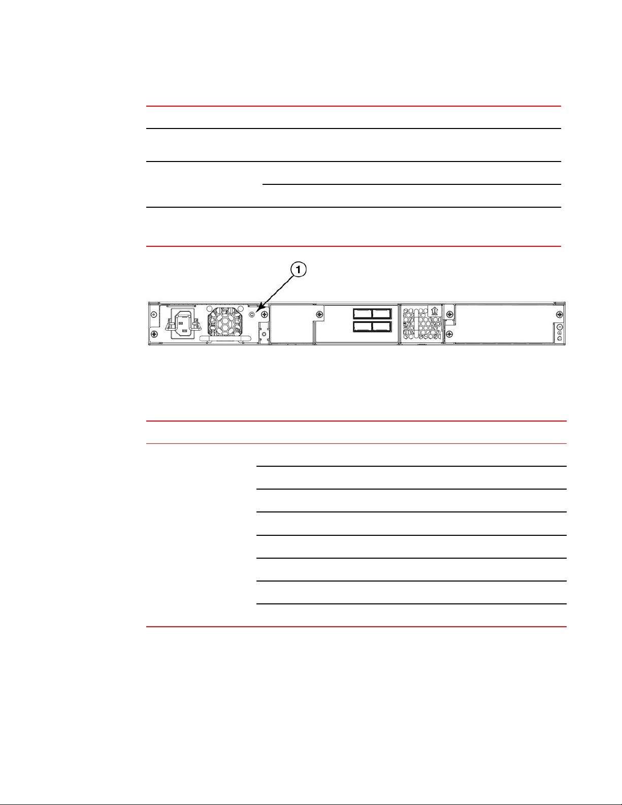
FIGURE 3 ICX 6610-24P rear panel
FIGURE 4 ICX 6610-48 and ICX 6610-48P front panels
FIGURE 5 ICX 6610-48P rear panels
FIGURE 6 ICX 6610-24, ICX 6610-48, and ICX 6610-24F rear panels
Management interfaces
Each ICX 6610 includes the following management interfaces:
• Console management interface (RJ45 serial port)
• Out-of-band management Interface (RJ45 port)
• Reset button
12 Brocade ICX 6610 Stackable Switch Hardware Installation Guide
53-1003082-02
Page 15
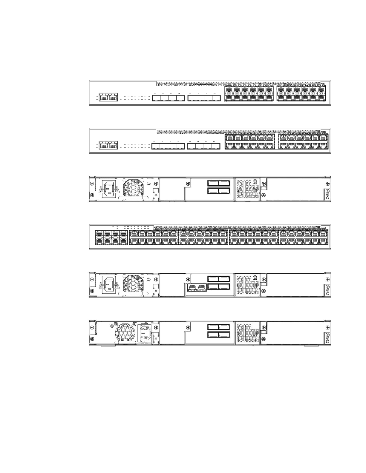
Console management interface
These RJ45 management ports are located together on the left side of the front panel on 24-port
models, and in the middle of the rear panel on 48P-port models.
1 Console port
2 Out-of-band management port
FIGURE 7 Management interfaces on 24-port models
1 Out-of-band management port
2 Console port
FIGURE 8 Management interfaces on 48P-port models
Console management interface
The console management interface is an RJ45 serial port that allows you to configure and manage the
device using a third-party terminal emulation application from a directly-connected PC.
Out-of-band management interface
The out-of-band management interface is an RJ45 port that allows you to configure and manage the
device from the network.
Reset button
The reset button allows you to restart the system without switching the power supplies off and on or
using the CLI or Web Management Interface. When the reset button is pressed, the system resets and
the software is reloaded. The reset button is located next to the PSU LED on both 24-port and 48-port
models.
Network interfaces for ICX 6610devices
ICX 6610-24, ICX 6610-24, ICX 6610-48, and ICX 6610-48P devices contain the following interfaces:
Brocade ICX 6610 Stackable Switch Hardware Installation Guide 13
53-1003082-02
Page 16
Slot locations
• 10/100/1000 Mbps ports with RJ45 copper connectors
• SFP/SFP+ ports
• QSFP stacking ports
ICX 6610-24F devices contain the following interfaces:
• 100/1000 SFP fiber ports
• SFP/SFP+ ports
• QSFP stacking ports
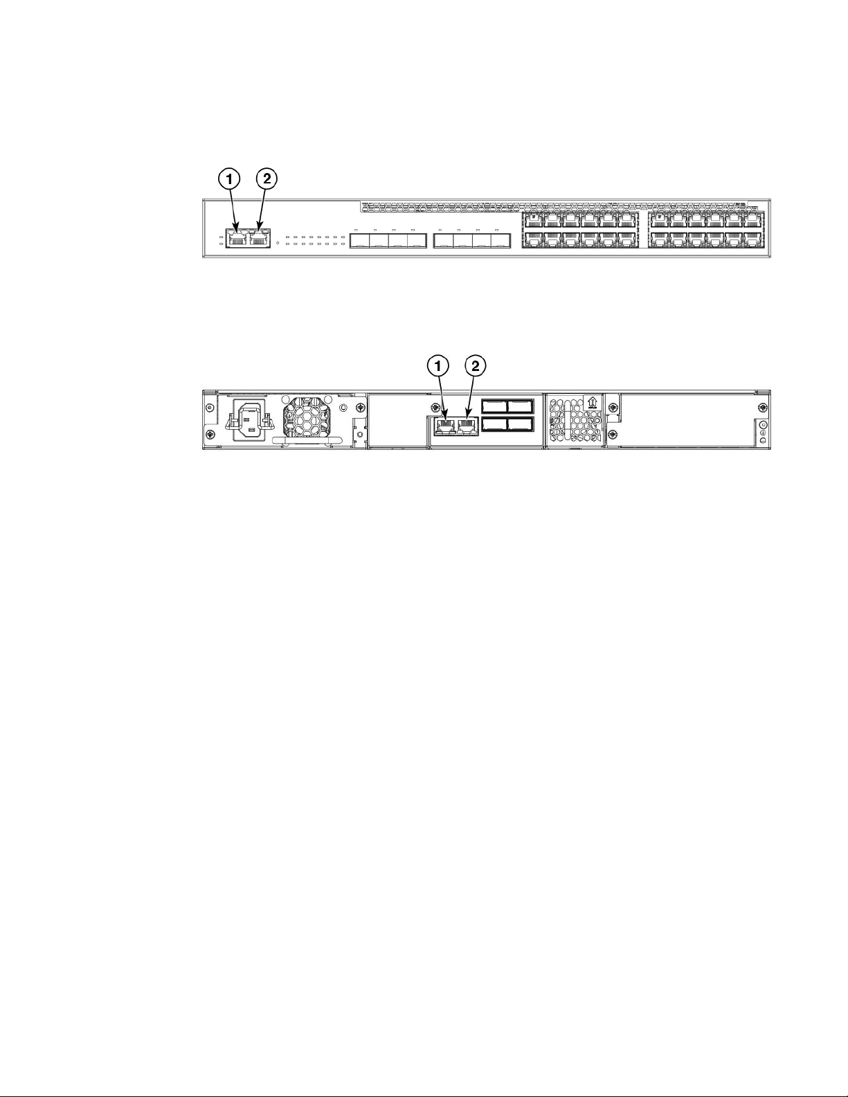
Slot locations
There are three slot locations on the ICX 6610: slots 3 and 1 on the front panel and slot 2 on the rear
panel.
FIGURE 9 Slot locations on the front panel of the 24-port model of the ICX 6610
1 Slot 3, SFP/SFP+ ports 2 Slot 1, 10/100/1000 Mbps ports
FIGURE 10 Slot locations on the front panel of the 48-port model of the ICX 6610
1
Slot 3, SFP/SFP+ ports 2 Slot 1, 10/100/1000 Mbps ports
The following figure shows slot 2 on the rear panel of the ICX 6610.
FIGURE 11 Slot location on the rear panel of the ICX 6610
14 Brocade ICX 6610 Stackable Switch Hardware Installation Guide
53-1003082-02
Page 17

Slot designations
1 Slot 2: Dedicated stacking ports 1, 2, 6, 7
Slot designations
The following table lists the slot designations for ICX 6610 models.
Stack unit slots for ICX 6610 stackable devices TABLE 1
Device Slot 1 Slot 2 Slot 3
ICX 6610-24 10/100/1000 Mbps ports 1-24 QSFP stacking ports 1, 2, 6, 7 SFP/SFP+ ports 1-8
ICX 6610-24F 100/1000 Mbps ports 1-24 QSFP stacking ports 1, 2, 6, 7 SFP/SFP+ ports 1-8
ICX 6610-24P 10/100/1000 Mbps ports 1-24 QSFP stacking ports 1, 2, 6, 7 SFP/SFP+ ports 1-8
ICX 6610-48 10/100/1000 Mbps ports 1-48 QSFP stacking ports 1, 2, 6, 7 SFP/SFP+ ports 1-8
ICX 6610-48P 10/100/1000 Mbps ports 1-48 QSFP stacking ports 1, 2, 6, 7 SFP/SFP+ ports 1-8
10/100/1000 BASE-T ports
All ICX 6610 copper devices provide 24 or 48 RJ45 ports that operate at 10 Mbps or 100 Mbps half or
full duplex, or at 1000 Mbps full duplex. In addition, ICX 6610 fiber models provide 24 SFP ports.
Because all ports support automatic MDI or MDI-X operation, you can use straight-through cables for all
network connections to PCs or servers, or to other switches or hubs. In addition, it is ideal (and
preferred) to use straight-through cable for switch-to-switch connections.
Each port supports auto-negotiation, so the optimum transmission mode (half or full duplex), and the
data rate (10, 100, or 1000 Mbps) can be selected automatically. If a device connected to one of these
ports does not support auto-negotiation, the communication mode of the port can be configured
manually.
SFP interfaces
The following table describes the SFP network interfaces supported on ICX 6610 devices.
Supported network interfacesTABLE 2
Interface show media command description
1000Base-BX-D M-GBXD
1000Base-BX-U M-GBXU
1000Base-LHA M-LHA
1000Base-LHB M-LHB
1000Base-LX M-LX
Brocade ICX 6610 Stackable Switch Hardware Installation Guide 15
53-1003082-02
Page 18

40-Gbps QSFP interface stacking ports
Supported network interfaces (Continued)TABLE 2
Interface show media command description
1000Base-SX M-SX
1000Base-T C
1000Base-TX M-TX
100Base-FX M-FX
40-Gbps QSFP interface stacking ports
ICX 6610 devices have two 40-Gbps QSFP stacking ports and two 4 x 10-Gbps QSFP stacking ports
on the rear panel. These ports can perform data transmission directly through copper links of up to 5
meters. ICX 6610 devices also support 40G-QSFP-SR4 at distances up to 100 meters.
Specifying a port address
You can specify a port address for a data port, stacking port, or a management port.
Specifying a data port
The port address format is stack unit/slot/port, where:
• stack unit --Specifies the stack unit ID. Range is from 1 to 8. If the device is not part of a stack, the
stack unit ID is 1.
• slot --Specifies the slot number. Can be 1 or 3.
• port --Specifies the port number in the slot. Range is from 1 to 24 (24-port models) or 1 to 48 (48port models).
This example shows how to specify port 2 in slot 1 of a device that is not part of a stack:
Brocade (config) # interface ethernet 1/1/2
Specifying a stacking port
The port address format is stack unit/slot/port, where:
• stack unit --Specifies the stack unit ID. Range is from 1 to 8.
• slot --Specifies the slot number. Stacking ports are in slot 2.
• port --Specifies the port number in the slot. Dedicated stacking ports are 1, 2, 6, and 7.
This example shows how to specify stacking port 2 in slot 2 of unit 3 in a stack:
Brocade (config) # interface ethernet 3/2/2
16 Brocade ICX 6610 Stackable Switch Hardware Installation Guide
53-1003082-02
Page 19
Specifying a management port
The management port number is always 1. This example shows how to specify the management port:
Brocade (config) # interface management 1
The Up Link and Down Link LEDs on the front panel indicate operational status. If the Up Link or Down
Link LED is on, the port is connected. If the Up Link or Down Link LED is off, no connection exists, or
the link is down.
Port, system, and power status LEDs
ICX 6610 devices include LEDs that indicate the status of device components. This section identifies
and describes these LEDs.
Specifying a management port
1 Port status LEDs
FIGURE 12 Port status LEDs
Port status LEDs TABLE 3
LED Condition Status
Ethernet(1~24/48) On/Flashing Green The port has established a valid link at 1000 Mbps.
On/Flashing Yellow The port has established a valid link at 10 or 100
Off A link is not established with a remote port.
PoE(1~24/48) On The port is providing PoE power to a connected
Off The port is not providing PoE power.
SFP/SFP+(1F~8F) On/Flashing Green The SFP port is operating at 10 Gbps. Flashing
Flashing indicates the port is transmitting and
receiving user packets.
Mbps. Flashing indicates the port is transmitting and
receiving user packets.
device.
indicates the port is transmitting and receiving user
packets.
Brocade ICX 6610 Stackable Switch Hardware Installation Guide 17
53-1003082-02
Page 20
ICX 6610 Overview
Port status LEDs (Continued)TABLE 3
LED Condition Status
Out of band management port (2
LEDs)
1 System status LEDs
On/Flashing Yellow The SFP port is operating at 1 Gbps. Flashing
Off A link is not established with a remote port.
Off (both LEDs) Offline
On/Flashing (right side) Link-up. Flashing indicates the port is transmitting
Green (left side) 1000Mbps Link-up
Left LED off, right LED
on or flashing
indicates the port is transmitting and receiving user
packets.
and receiving user packets.
10/100Mbps Link-up. Flashing indicates the port is
transmitting and receiving user packets.
FIGURE 13 System status LEDs
System status LEDs TABLE 4
LED Condition Status
PS1
PS2
(Power Supply Status)
Diag
(Diagnostic)
MS
(Stacking configuration)
Green Power supply is operating normally.
Yellow Power supply fault.
Off Power off or failure.
Flashing Green System self-diagnostic test in progress.
Green System self-diagnostic test successfully completed.
Yellow System self-diagnostic test has detected a fault. (Blower,
thermal or any interface fault.)
Green The device is the Active controller. Flashing indicates the
system is initializing.
Yellow Indicates the device is the Standby controller. Flashing indicates
the system is in Master arbitration/selection state.
18 Brocade ICX 6610 Stackable Switch Hardware Installation Guide
53-1003082-02
Page 21
System status LEDs (Continued)TABLE 4
LED Condition Status
ICX 6610 Overview
XL1, XL2-XL5, XL6, XL7-XL10
(Stacking port status)
1-10+
(Stack ID)
1 Power status LED
Off Device is operating as a stack member, or is in standalone
Green Port is operating normally.
Off Link has failed or there is no link.
Green Indicates the device stack ID.
mode.
FIGURE 14 Power status LED on 48P-port models
Power status LED TABLE 5
LED Condition Status
Power status Green (steady) Nominal
Off No input power
Flash 55 V out of range
Flash 12 V out of range
Off AC input under voltage
Flash Fan fault
Flash OTP
Flash PSU disabled
Brocade ICX 6610 Stackable Switch Hardware Installation Guide 19
53-1003082-02
Page 22

Fan trays
1 Fan tray LED
FIGURE 15 Fan tray status LED on 48P-port models
Fan tray status LEDTABLE 6
LED Condition Status
Fan Status Green Fan is operating normally
Yellow Fan failure
Fan trays
The device has two fan tray receptacles on the rear panel. Each device ships with one fan tray
installed. A secondary fan tray can be installed. Fan trays are hot-swappable. For instructions on
installing and replacing a fan tray refer to Installing or replacing fan trays section.
Power supplies
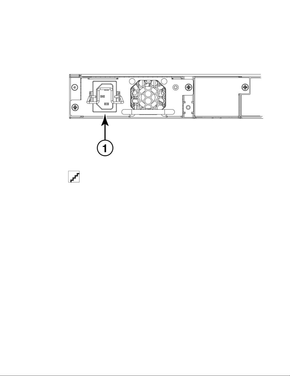
The device has two power supply receptacles on the rear panel. Each device ships with one AC power
supply installed. Each power supply has one standard power receptacle for the AC power cable. A
secondary AC power supply can be installed to provide backup power in case of a failure and for loadbalancing when both power supplies are operational. AC power supplies can be hot swapped.
DC power supplies are available for the device. A secondary DC power supply can be installed for
backup and load-balancing when both power supplies are operational. DC power supplies can also be
hot swapped.
Note: AC and DC power supplies cannot be installed and used in the same device. Mismatched power
supplies in the same device cause continual reboot on power up.
20 Brocade ICX 6610 Stackable Switch Hardware Installation Guide
53-1003082-02
Page 23
PoE and PoE+ power
For instructions on installing and replacing a power supply refer to Installing and replacing a power
supply unit on page 53 section. For information on LED status refer to Power status LEDs table in the
section Port, system, and power status LEDs on page 17.
FIGURE 16 ICX 6610 AC power supply receptacle on 48-port models
1. AC power receptacle
1 DC power receptacle
FIGURE 17 ICX 6610 DC power supply receptacle on 48-port models
PoE and PoE+ power
The 1000W power supply provides 250W for the system and 750W for PoE. A device with two 1000W
power supplies installed provides 1500W for PoE. The total power allocation of all PoE ports on a
device cannot exceed the maximum PoE power available from the device. For example, each 1000W
power supply supports a maximum of 24 PoE+ (30W) ports.
Brocade ICX 6610 Stackable Switch Hardware Installation Guide 21
53-1003082-02
Page 24

PoE and PoE+ power
22 Brocade ICX 6610 Stackable Switch Hardware Installation Guide
53-1003082-02
Page 25
Installing the ICX 6610 Switch
● Unpacking the device......................................................................................................23
● Installation tasks..............................................................................................................24
● Installation precautions................................................................................................... 25
● Preparing the installation site.......................................................................................... 26
● Installing the device.........................................................................................................27
● Connecting devices in a traditional stack........................................................................ 36
● Connecting devices in a mixed stack.............................................................................. 41
● Attaching a PC or terminal.............................................................................................. 51
● Powering on the system..................................................................................................52
● Power supplies for the Brocade ICX 6610...................................................................... 52
● Installing or replacing fan trays....................................................................................... 59
CAUTION
The procedures in this manual are intended for qualified service personnel.
CAUTION
Before beginning the installation, see the precautions in Power precautions on page 25.
Unpacking the device
ICX 6610 devices ship with all of the items in the following list. Verify the contents of your shipping
container. If any items are missing, contact the place of purchase.
Package contents
The following items are included in your shipping carton:
• ICX 6610 device
• AC power cable for North America (not included for models with DC power supply)
• Two 1M Passive copper QSFP stacking cable (not included for models with DC power supply)
• Two mounting ears and screws
• 4 rubber feet
• Grounding terminal
General requirements
To manage the ICX 6610, you need a management station, such as a PC running a terminal emulation
application. Connect the management station to the Console serial port on the switch.
Brocade ICX 6610 Stackable Switch Hardware Installation Guide
53-1003082-02
23
Page 26

Installation tasks
Use the serial connection to perform basic configuration tasks, including assigning an IP address and
network mask to the system. This information is required to manage the system using the IronView
Network Manager or using the CLI through Telnet or SSH.
Installation tasks
Details for the following tasks are documented in the sections of this document noted in the “Where To
Find More Information” column.
Installation tasks TABLE 7
Task Number Task Where to Find More
1 Ensure that the physical environment that will host the device
has the proper cabling and ventilation.
2 Install any required optional modules into the device. See “Powering on the system”
3 Install the device on a desktop, or in an equipment rack. See “Installing the device”
4 Once the device is installed, plug the device into a nearby
power source that adheres to the regulatory requirements
outlined in this manual.
5 Attach a terminal or PC to the device. This will enable you to
configure the device through the Command Line Interface
(CLI) .
6 No default password is assigned to the CLI. For additional
access security, assign a password.
7 Before attaching equipment to the device, you need to
configure an interface IP address to the subnet on which the
device will be located. Initial IP address configuration is
performed using the CLI with a direct serial connection.
Subsequent IP address configuration can also be performed
using the CLI through Telnet or SSH.
Information
See “Preparing the installation
site” section.
section.
section.
See “Powering on the system”
section.
See “Attaching a PC or terminal”
section.
See “Assigning permanent
passwords” section.
See “Configuring IP addresses”
section.
8 Once you power on the device and assign IP addresses, the
system is ready to accept network equipment.
9 Test IP connectivity to other devices by pinging them and
tracing routes.
10 Continue configuring the device using the CLI through Telnet
or SSH. You also can use IronView Network Manager to
manage the device.
11 Secure access to the device. FastIron Ethernet Switch
24 Brocade ICX 6610 Stackable Switch Hardware Installation Guide
See “Configuring IP addresses”
section.
See “Testing connectivity”
section.
FastIron Ethernet Switch
Administration Guide
Security Configuration Guide
53-1003082-02
Page 27
Installation precautions
Follow all precautions when installing a device.
General precautions
CAUTION
All fiber-optic interfaces use Class 1 lasers.
CAUTION
Do not install the device in an environment where the operating ambient temperature might
exceed 40 ο C (104 ο F).
Installation precautions
CAUTION
Make sure the air flow around the front and sides of the device is not restricted.
CAUTION
Never leave tools inside the device.
CAUTION
Risk of explosion if battery is replaced by an incorrect type. Dispose of used batteries according
to the instructions.
Lifting precautions
CAUTION
Make sure the rack or cabinet housing the device is adequately secured to prevent it from
becoming unstable or falling over.
Power precautions
CAUTION
Use a separate branch circuit for each power cord, which provides redundancy in case one of
the circuits fails.
Brocade ICX 6610 Stackable Switch Hardware Installation Guide 25
53-1003082-02
Page 28
Preparing the installation site
CAUTION
To avoid high voltage shock, do not open the device while the power is on.
CAUTION
Ensure that the device does not overload the power circuits, wiring, and over-current
protection. To determine the possibility of overloading the supply circuits, add the ampere
(amp) ratings of all devices installed on the same circuit as the device. Compare this total with
the rating limit for the circuit. The maximum ampere ratings are usually printed on the devices
near the input power connectors.
CAUTION
Disconnect the power cord from all power sources to completely remove power from the
device.
CAUTION
Before plugging a cable to any port, be sure to discharge any static charge stored on the cable
by touching the electrical contacts to ground surface.
CAUTION
If the installation requires a different power cord than the one supplied with the device, make
sure you use a power cord displaying the mark of the safety agency that defines the
regulations for power cords in your country. The mark is your assurance that the power cord
can be used safely with the device.
Preparing the installation site
Before installing the device, plan its location and orientation relative to other devices and equipment.
Cabling infrastructure
Ensure that the proper cabling is installed at the site. Refer to the "Hardware Specifications" chapter or
www.brocade.com for a summary of supported cabling types and their specifications.
Installation location
Before installing the device, plan its location and orientation relative to other devices and equipment.
Devices can be mounted in a standard 19-inch equipment rack or on a flat surface. Be sure to follow
the guidelines below when choosing a location.
The site should meet the following requirements:
26 Brocade ICX 6610 Stackable Switch Hardware Installation Guide
53-1003082-02
Page 29

Installing the device
• Maintain the operating environment as specified in the Environmental considerationssection .
• Temperatures within 0 to 40 ο C (32 to 104 ο F) and humidity levels within 5% to 95%, noncondensing.
• Allow a minimum of 3 in. of space between the front and the back of the device and walls or other
obstructions for proper air flow.
• Allow at least 3 in. of space at the front and back of the device for the twisted-pair, fiber-optic, and
power cabling.
• Be accessible for installing, cabling and maintaining the devices.
• Allow the status LEDs to be clearly visible.
• Allow for twisted-pair cable to be always routed away from power lines, fluorescent lighting fixtures
and other sources of electrical interference, such as radios and transmitters.
• Allow for the unit to be connected to a separate grounded power outlet that provides 100 to 240
VAC, 50 to 60 Hz, is within 2 m (6.6 feet) of each device, and is powered from an independent
circuit breaker. As with any equipment, a filter or surge suppressor is recommended.
• Some combinations of intake and exhaust airflows may not be compatible with your environment.
Consult your fan and power supply module FRU kit to determine the correct configuration.
• For a 4-post rail mount configuration, order the appropriate mounting kit and refer to the kit
documentation.
Installing the device
You can install the device on a desktop or in an equipment rack.
CAUTION
Make sure the rack or cabinet housing the device is adequately secured to prevent it from
becoming unstable or falling over.
Brocade ICX 6610 Stackable Switch Hardware Installation Guide 27
53-1003082-02
Page 30
Desktop installation
Desktop installation
Use the following steps to install the ICX 6610 on a desktop or other flat surface.
FIGURE 18 Attaching the adhesive feet
1. Attach the four adhesive feet to the bottom of the first switch.
2. Set the device on a flat desktop, table, or shelf near an AC power source. Make sure that
adequate ventilation is provided for the system. A 3 inch clearance is recommended on each side.
3. If installing a single switch only, refer to Powering on the system section.
4. If installing multiple switches, attach the adhesive feet to each one. Place each device squarely on
top of the one below, in any order.
Rack mount installation
NOTE
You will need a Phillips screwdriver for installation.
Before mounting the switch in a rack, pay particular attention to the following factors:
• Temperature: Because the temperature within a rack assembly may be higher than the ambient
room temperature, check that the rack-environment temperature is within the specified operating
temperature range.
• Mechanical loading: Do not place any equipment on top of a rack-mounted unit.
• Circuit overloading: Be sure that the supply circuit to the rack assembly is not overloaded.
• Grounding: Rack-mounted equipment should be properly grounded. Be sure to check supply
connections in addition to direct connections to the mains.
28 Brocade ICX 6610 Stackable Switch Hardware Installation Guide
53-1003082-02
Page 31

2-Post rack mount installation
2-Post rack mount installation
NOTE
Use the following procedure when installing the Brocade ICX 6610 device in a 2-post rack. For 4-post
racks, follow the procedures in the section 4-Post rack mount installation on page 33.
Remove the rack mount kit from the shipping carton. The kit contains the following:
• Two L-shaped mounting brackets.
• Sixteen 8-32 x 3/8 in., panhead Phillips screws with patchlocks.
• Four 10-32 x 5/8 in., panhead Phillips screws (torque to 25 in-lb, 29 cm-kg)
• Eight 32-10 retainer nuts (for square-hole rack rails)
• Eight 32-10 retainer nuts (for round-hole rack rails)
1 Bracket, front right
2 Bracket, front left
3 Screw, 8-32 x 3/8 in., panhead Phillips
4 Screw, 10-32 x 5/8 in., panhead Phillips
5 Retainer nut, 10-32, (for square-hole
rack rails)
6 Retainer nut, 10-32, (for round-hole
rack rails)
FIGURE 19 2-post rack mount kit for Brocade ICX 6610
Brocade ICX 6610 Stackable Switch Hardware Installation Guide 29
53-1003082-02
Page 32

Installing the ICX 6610 Switch
Use the following steps to mount devices in a 2-post rack.
1. Attach the mounting brackets to the sides of the device using the 8-32 x 3/8 in. screws.
There are two sets of holes, labeled "A" or "B". Use the holes labeled "A" if you want the device to
be flushed with the rack rails.
1 Bracket
2 32 x 3/8 in. screws
FIGURE 20 Attaching the brackets on an Brocade ICX 6610, flush rail mounting
Use the holes labeled "B" if you want the device to protrude 4-1/2 inches from the front of the rail
rack .
30 Brocade ICX 6610 Stackable Switch Hardware Installation Guide
53-1003082-02
Page 33

Installing the ICX 6610 Switch
1 Bracket
2 - 32 x 3/8 in. screws
FIGURE 21 Attaching the brackets on a ICX 6610 devices, mid rail mounting
2. Position the switch in the cabinet, providing temporary support under the switch until the rail kit is
secured to the cabinet.
Brocade ICX 6610 Stackable Switch Hardware Installation Guide 31
53-1003082-02
Page 34

Installing the ICX 6610 Switch
3. Attach the front right bracket to the rail rack using two 10-32 x 5/8 in. screws and the appropriate
round or square retainer nuts.
FIGURE 22 Installing the device, flush rail mounting
FIGURE 23 Installing the device, mid rail mounting
4. Repeat Step 1 to Step 3 to attach the left front bracket to the left front rack rail and tighten all
10-32 x 5/8 in. screws to a torque of 25 in-lb (29 cm-kg).
32 Brocade ICX 6610 Stackable Switch Hardware Installation Guide
53-1003082-02
Page 35

4-Post rack mount installation
4-Post rack mount installation
Kits for 4-post rack mounting are not included in the shipping carton and must be ordered separately.
NOTE
Use the following procedure when installing the Brocade ICX 6610 device in a 4-post rack cabinet. For
2-post cabinets, follow the procedures in the “2-Post rack mount installation” section.
Remove the rack mount kit from the shipping carton. The kit contains the following:
• ‐ Two mounting brackets.
‐ Two pairs of extension brackets. Use the shorter pair for rack that are up 27 inches deep.
Use the longer pair for racks up to 32 inches deep.
‐ Thirty-two 8-32 x 3/8 in., panhead Phillips screws with patchlocks.
‐ Eight 10-32 x 5/8 in., panhead Phillips screws (torque to 25 in-lb, 29 cm-kg).
Brocade ICX 6610 Stackable Switch Hardware Installation Guide 33
53-1003082-02
Page 36

Installing the ICX 6610 Switch
‐ Eight 32-10 retainer nuts (for square-hole rack rails).
‐ Eight 32-10 retainer nuts (for round-hole rack rails)
1 Bracket, front right
2 Bracket, front left
3 Bracket extensions up to 34 in.
4 Bracket extensions, up to 27 in.
5 Screw, 8-32 x 3/8 in., panhead Phillips
6 Screw, 10-32 x 5/8 in., panhead Phillips
7 Retainer nut, 10-32, (for square-hole
rack rails)
8 Retainer nut, 10-32, (for round-hole
rack rails)
FIGURE 24 4-post rail kit
Use the steps below to mount devices in a 4-post rack.
CAUTION
Do not use the hardware supplied in a 2-post rack mounting kit to mount a Brocade ICX 6610
device in a 4-post rack. Mounting the device in a 4-post rack requires additional hardware to
prevent drooping from possible flexing and distortion of the 4-post rack when a device is not
properly installed.
1. Attach the mounting brackets to the sides of the device, using the 8-32 x 3/8 in. screws.
34 Brocade ICX 6610 Stackable Switch Hardware Installation Guide
53-1003082-02
Page 37

Installing the ICX 6610 Switch
1 Bracket
2 - 32 x 3/8 in. screws
FIGURE 25 Attaching 4-post brackets
2. Attach the appropriate extensions as required for the type of rack in which you are installing the
device.
Bracket
1
2 32 x 3/8 in. screws
FIGURE 26 Attaching bracket extensions
Brocade ICX 6610 Stackable Switch Hardware Installation Guide 35
53-1003082-02
Page 38

Connecting devices in a traditional stack
3. Position the switch in the cabinet, providing temporary support under the switch until the rail kit is
secured to the cabinet.
4. Attach the brackets to the front and back rails, using the 10-32 x 5/8 in. screws and the
appropriate round or square retainer nuts.
FIGURE 27 Attaching device to a 4-post rack
Connecting devices in a traditional stack
ICX 6610 devices can operate as standalone devices and also as members of a traditional stack. A
stack is a group of devices (Brocade stackable units and their connected stacking links) that are
connected so that the stack is managed as a single entity. A traditional stack contains devices from
only one model in a product family.
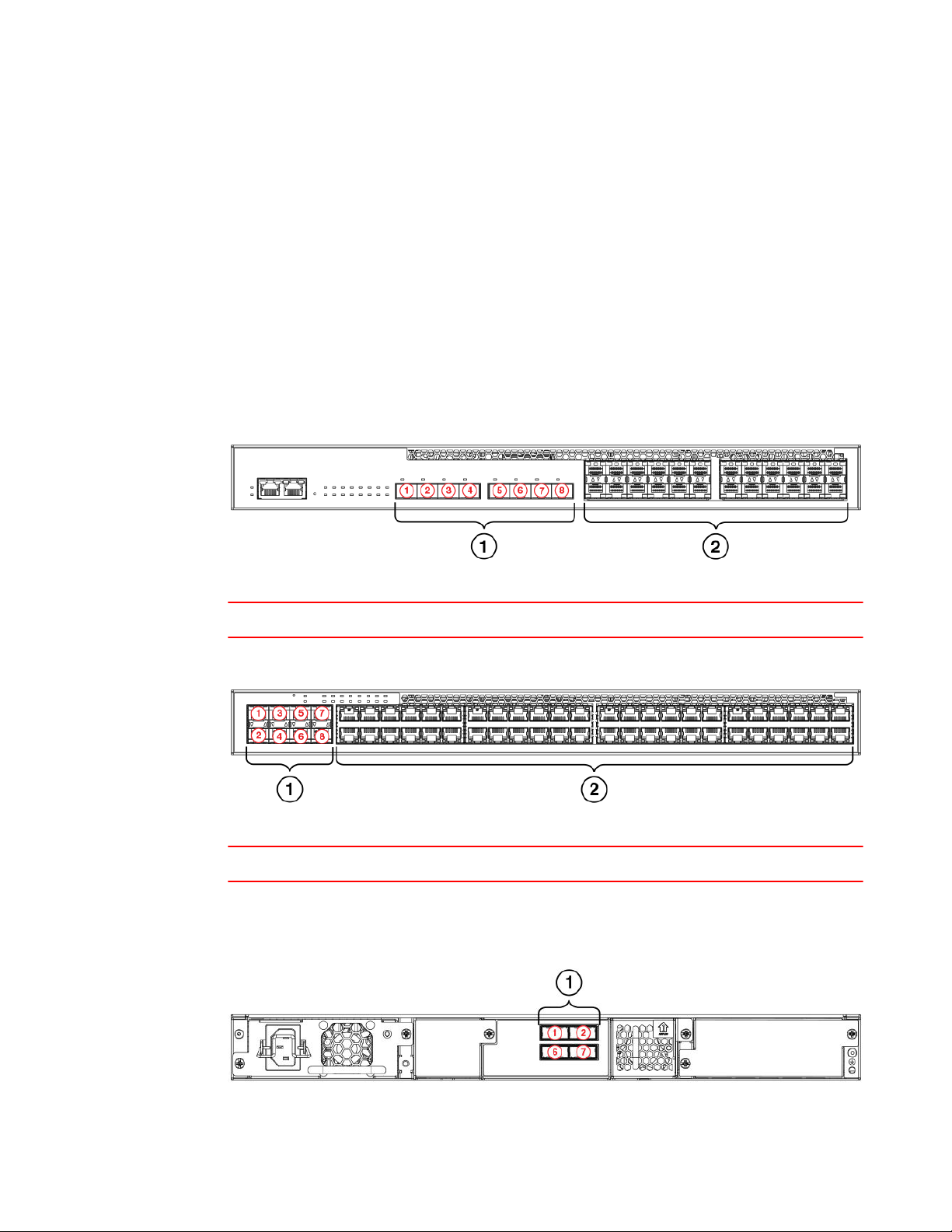
Stacking ports and trunks
The ICX 6610 device contains four ports in slot 2 on the rear panel that are dedicated stacking ports.
They cannot be used as data ports, even when stacking is not enabled. There are two 40 Gbps ports
and two 4 x 10 Gbps ports arranged in two rows.
The stacking ports can be grouped into two trunks. Ports 1 and 2 on the top row can form trunk 0;
ports 6 and 7 on the bottom row can form trunk 1.
You can trunk stacking ports by connecting one port of each type (40 Gbps or 4 x 10 Gbps) to ports of
the same type on another ICX 6610 device in the stack. The following figure shows the stacking ports
and trunks.
36 Brocade ICX 6610 Stackable Switch Hardware Installation Guide
53-1003082-02
Page 39

Trunking requirements
1 1-Port 1, 40 Gbps
2 2-Trunk 0
3 3-Port 2, 4 x 10 Gbps
4 4- Port 6, 40 Gbps
5 5-Trunk 1
6 6- Port 7, 4 x 10 Gbps
FIGURE 28 Dedicated stacking ports and trunks in slot 2 on ICX 6610 devices
Trunking requirements
• You can connect one or both ports in a trunk. Connecting both ports in a trunk increases stacking
bandwidth and provides resiliency.
• You must connect each port type (40 Gbps or 4x10 Gbps) to the same type of port on another
device as shown in the following table.
• If you connect both ports in a trunk, both ports must connect to both ports of one trunk on another
device.
Port connections for trunking between ICX 6610 devices TABLE 8
Valid port connections Invalid port connections
Device 1 Device 2 Device 1 Device 2
Port 1 to Port 1 Port 1 to Port 2
Port 1 to Port 6 Port 1 to Port 7
Port 2 to Port 2 Port 2 to Port 1
Port 2 to Port 7 Port 2 to Port 6
Stacking configuration requirements
Before configuring the traditional stack using the CLI, physically connect the devices using stacking
cables. For information about configuring a stack, refer to the FastIron Ethernet Switch Stacking
Configuration Guide.
Stacking cables
Use 1 meter passive copper QSFP stacking cables or SFP+ fiber-optic cables to connect ICX 6610
devices in a traditional stack. 40G-QSFP-SR4 is also supported.
Brocade ICX 6610 Stackable Switch Hardware Installation Guide 37
53-1003082-02
Page 40

Stack size
Stack size
A traditional stack can contain a maximum of eight ICX 6610 devices.
Stacking topologies
Both linear and ring topologies are supported in a traditional stack. In a linear stack topology, there is a
connection between each switch that carries two-way communications across the stack. This
connection can use one port or two ports per trunk.
For example, in a four-unit stack using a linear topology, unit 1 connects to unit 2, unit 2 to unit 3, and
unit 3 to unit 4.
In ring stack topology, there is an extra connection between the logical first and last devices to form a
"ring" or "closed-loop." The closed-loop connection provides a redundant path for the stack link, so if
one link fails, stack communications can be maintained.
For example, in a four-unit stack using a ring topology, unit 1 connects to unit 2, unit 2 to unit 3, unit 3
to unit 4, and unit 4 connects to unit 1.
You can connect stacking units using one port per trunk or both ports in a trunk. For maximum
bandwidth and link redundancy, use both ports per trunk.
The following figures show supported stacking topologies:
38 Brocade ICX 6610 Stackable Switch Hardware Installation Guide
53-1003082-02
Page 41

Installing the ICX 6610 Switch
• Linear stacking topology using both ports in each trunk
• Linear (top) and ring (bottom) stacking topologies using one port per trunk
• Ring stacking topology using both ports in each trunk
FIGURE 29 Linear stacking topology using both ports in each trunk
FIGURE 30 Linear and ring stacking topologies using one port per trunk
Brocade ICX 6610 Stackable Switch Hardware Installation Guide 39
53-1003082-02
Page 42

Installing the ICX 6610 Switch
FIGURE 31 Ring stacking topology using both ports in each trunk
40 Brocade ICX 6610 Stackable Switch Hardware Installation Guide
53-1003082-02
Page 43

Connecting devices in a mixed stack
ICX 6610 devices can operate as standalone devices and also as members of a mixed stack. A stack is
a group of devices (Brocade stackable units and their connected stacking links) that are connected so
that the stack is managed as a single entity.
A mixed stack contains ICX 6610 devices and ICX 6450 devices. ICX 6610 devices form the backbone
of the mixed stack. ICX 6450 devices are peripheral units that connect to the backbone and to other
peripheral units.
The following table summarizes the ports used in mixed stacking.
Stacking ports used in mixed stacking TABLE 9
Device Stacking ports Panel/slot Ports Speed Connection type
Connecting devices in a mixed stack
ICX 6610 Dedicated stacking Rear/2 1, 6,
2, 7
ICX 6610 SFP+ Front/3 1-8 10 Gbps Backbone to peripheral:
ICX 6450 SFP+ Front/2 1-4 10 Gbps Peripheral to backbone:
40 Gbps
4 x 10 Gbps
Backbone to backbone:
ICX 6610 to ICX 6610
ICX 6610 to ICX 6450
ICX 6450 to ICX 6610
Peripheral to peripheral:
ICX 6450 to ICX 6450
ICX 6610 stacking ports and trunks
This section discusses the ports you can use to connect ICX 6610 devices in the backbone and to ICX
6450 devices.
Ports used to connect ICX 6610 devices in the backbone
The ICX 6610 device contains four ports in slot 2 on the rear panel that are dedicated stacking ports.
They cannot be used as data ports, even when stacking is not enabled. There are two 40 Gbps ports
and two 4 x 10 Gbps ports arranged in two rows.
The stacking ports can be grouped into two trunks. Ports 1 and 2 on the top row can form trunk 0; ports
6 and 7 on the bottom row can form trunk 1.
Brocade ICX 6610 Stackable Switch Hardware Installation Guide 41
53-1003082-02
Page 44

Trunking requirements
You can trunk stacking ports by connecting one port of each type (40 Gbps or 4 x 10 Gbps) to ports of
the same type on another ICX 6610 device in the stack. The following figure shows the stacking ports
and trunks.
FIGURE 32 Dedicated stacking ports and trunks on the rear panel of an ICX 6610 device
• 1-Port 1, 40 Gbps
• 2-Trunk 0
• 3-Port 2, 4 x 10 Gbps
• 4-Port 6, 40 Gbps
• 5-Trunk 1
• 6-Port 7, 4 x 10 Gbps
Trunking requirements
• You can connect one or both ports in a trunk. Connecting both ports in a trunk increases stacking
bandwidth and provides resiliency.
• You must connect each port type (40 Gbps or 4x10 Gbps) to the same type of port on another
device as shown in the following table.
Port connections for trunking between ICX 6610 devices TABLE 10
Valid port connections Invalid port connections
Device 1 Device 2 Device 1 Device 2
Port 1 to Port 1 Port 1 to Port 2
Port 1 to Port 6 Port 1 to Port 7
Port 2 to Port 2 Port 2 to Port 1
• If you connect both ports in a trunk, both ports must connect to both ports of one trunk on another
device.
NOTE
If you use the Secure Setup utility to set up a mixed stack, the stacking units (ICX 6610 devices and
ICX 6450 devices) are automatically trunked.
42 Brocade ICX 6610 Stackable Switch Hardware Installation Guide
53-1003082-02
Page 45

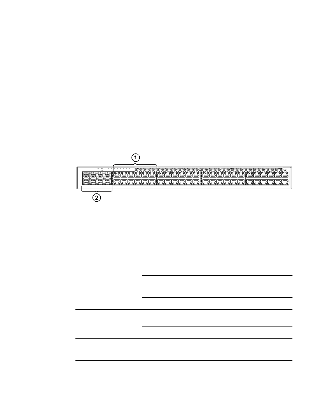
Ports used to connect ICX 6610 devices to ICX 6450 devices
Ports used to connect ICX 6610 devices to ICX 6450 devices
There are eight SFP+ ports in slot 3 on the front panel of an ICX 6610 device that are used to connect
ICX 6610 devices to ICX 6450 devices in a mixed stack.
NOTE
Without a license at bootup, the SFP+ ports come up in 10 Gbps port speed in an error-disabled state.
To enable the SFP+ ports to 10 Gbps port speed, you must purchase the ICX6610-10G-LIC-POD
license for each ICX 6610 SFP+ port that connects to an ICX 6450 device.
Maximum number of ports you can use on an ICX 6610 device to connect to ICX 6450 devices
Any one ICX 6610 device supports a maximum of:
• Two trunk connections to ICX 6450 peripheral devices (four ports total).
• Two single (untrunked) port connections to ICX 6450 peripheral devices.
FIGURE 33 SFP+ ports on the front panel of the 24-port model of an ICX 6610 device
1 Slot 3: 10 Gbps SFP+ ports 1-8 2 Slot 1: 10/100/1000 Mbps ports
FIGURE 34 SFP+ ports on the front panel of the 48-port model of an ICX 6610 device
1 Slot 3: 10 Gbps SFP+ ports 1-8 2 Slot 1: 10/100/1000 Mbps ports
Brocade ICX 6610 Stackable Switch Hardware Installation Guide 43
53-1003082-02
Page 46

ICX 6450 stacking ports and trunks
ICX 6450 stacking ports and trunks
The ICX 6450 contains four SFP+ ports in slot 2 on the front panel that can be used as uplink (data)
ports or as stacking ports. The following figure shows the ports in slot 2; the top row consists of ports 1
and 3, and the bottom row consists of ports 2 and 4.
FIGURE 35 Stacking ports on the front panel of an ICX 6450 device
• 1- Console port
• 2- Slot 2 (SFP and SFP + uplink or stacking ports)
• 3- Out-of-band management port
• 4- Slot 1 (10/100/1000 Mbps ports)
Ports 1 and 3 are default stacking ports. Default stacking ports have the capability to accept special
stacking packets during a CLI-initiated command sequence of the Secure Setup utility. If ports 1 and 3
are not used as stacking ports, you can use them as data ports. Configuration is not required to use
them as data ports.
All four ports in slot 2 can be used as stacking ports.
The stacking ports can be grouped into two trunks. Ports 1 and 2 can form a trunk; ports 3 and 4 can
form another trunk. By default, ICX 6450 devices are not configured for trunking.
On the ICX 6450, ports 1 and 3 are 10 Gbps ports. Without a license at bootup, ICX 6450 ports 2 and
4 come up in 10 Gbps port speed in an error disabled state. To enable ports 2 and 4 to 10 Gbps port
speed, you must purchase the ICX6450-2X10G-LIC-POD license. For more information about
enabling ports 2 and 4 to 10 Gbps port speed, refer to the FastIron Ethernet Switch Administration
Guide.
Trunking requirements
• You can connect one or both ports in a trunk. Connecting both ports in a trunk increases stacking
bandwidth and provides resiliency.
• If you connect both ports in a trunk, both ports must connect to both ports of one trunk on another
device.
• When configuring a trunk, the ports in the same column are always trunked (port 1 to port 2, port
3 to port 4). One or both of the two sets of stacking ports can be trunked (or untrunked).
• For ICX 6450 devices, all stacking ports must be configured to 10 Gbps port speed to enable
trunking.
NOTE
If you use the Secure Setup utility to set up a mixed stack, the stacking units (ICX 6610 devices and
ICX 6450 devices) are automatically trunked.
44 Brocade ICX 6610 Stackable Switch Hardware Installation Guide
53-1003082-02
Page 47

Stacking configuration requirements
Stacking configuration requirements
Before configuring the mixed stack, physically connect the devices using stacking cables.
All configuration methods
Before configuring the mixed stack, physically connect the devices using stacking cables.
Secure Setup utility
To use the 10 Gbps SFP+ ports on the front panel of ICX 6610 devices to connect ICX 6610 devices to
ICX 6450 devices in a mixed stack, configure the SFP+ ports on the ICX 6610 devices to 10 Gbps using
the speed command.
Automatic and manual configuration methods
To connect an ICX 6610 device in the backbone to an ICX 6450 device (peripheral unit), configure the
peri-port command or peri-trunk command on the ICX 6610 device
For information about configuring a stack, see the FastIron Ethernet Switch Stacking Configuration
Guide.
Stacking cables
The following table shows the cables to connect devices in a mixed stack.
Cables to connect devices in a mixed stack TABLE 11
To connect this device To this device Use this cable
ICX 6610 ICX 6610 1 meter passive copper QSFP stacking cable
100 meter QSFP fiber-optic cable
ICX 6450 ICX 6450 SFP+ fiber-optic cable
10 Gbps copper stacking cable
ICX 6610 ICX 6450 SFP+ fiber-optic cable
10 Gbps copper stacking cable
Stack size
A mixed stack can contain one or two ICX 6610 devices. They form the backbone of the mixed stack.
ICX 6450 devices are peripheral units. There can be one to six ICX 6450 devices in a mixed stack.
Peripheral devices can form one or more substacks. A substack is a topology that is formed by ICX
6450 devices. If ICX 6450 devices are separated by an ICX 6610 device, the ICX 6450 devices belong
to different substacks.
Brocade ICX 6610 Stackable Switch Hardware Installation Guide 45
53-1003082-02
Page 48

Stacking topologies
Stacking topologies
Two basic ring topologies are supported in a mixed stack: single ring and dual ring.
In a linear stack topology, there is a connection between each switch that carries two-way
communications across the stack. This connection can use one port or two ports per trunk.
In ring stack topology, there is an extra connection between the logical first and last devices to form a
"ring" or "closed-loop." The closed-loop connection provides a redundant path for the stack link, so if
one link fails, stack communications can be maintained.
For example, in a four-unit stack using a ring topology, unit 1 connects to unit 2, unit 2 to unit 3, unit 3
to unit 4, and unit 4 connects to unit 1.
You can connect stacking units using one port per trunk or both ports in a trunk. For maximum
bandwidth and link redundancy, use both ports per trunk on all stack units.
Topology 1: Single ring
In the following figure, two ICX 6610 devices form the backbone, and there are three ICX 6450
peripheral devices. There can be up to six ICX 6450 peripheral devices.
46 Brocade ICX 6610 Stackable Switch Hardware Installation Guide
53-1003082-02
Page 49

Topology 2: Dual ring
This is a single ring configuration in which the second ICX 6610 device is connected to the first ICX
6450 device, and the first ICX 6610 device is connected to the last ICX 6450 device. There is one
substack that contains three peripheral devices.
FIGURE 36 Topology 1: Single ring
Topology 2: Dual ring
In the following figure, two ICX 6610 devices form the backbone, and there are six ICX 6450 peripheral
devices in two rings. This is a dual ring configuration.
The first ICX 6610 device is connected to the last ICX 6450 device in the "vertical" ring. The backbone
devices are also connected to the first and last ICX 6450 devices in the "horizontal" ring.
Brocade ICX 6610 Stackable Switch Hardware Installation Guide 47
53-1003082-02
Page 50

Topology 3: Linear and ring
There are two substacks, each containing three peripheral devices.
FIGURE 37 Topology 2: Dual ring
Topology 3: Linear and ring
In the following figure, two ICX 6610 devices form the backbone, and there are six ICX 6450
peripheral devices in two substacks. Each substack contains three peripheral devices.
One substack is connected to one ICX 6610 device to form a linear topology. The other substack is
connected to each of the ICX 6610 devices to form a ring topology.
48 Brocade ICX 6610 Stackable Switch Hardware Installation Guide
53-1003082-02
Page 51

Topology 4: Ring with one backbone device
Topology 3 is almost identical to topology 2, except that the "horizontal" substack is not connected to
the second ICX 6610 device, either by design or because the link is broken. This is still a valid topology.
FIGURE 38 Topology 3: Linear and ring
Topology 4: Ring with one backbone device
In the following figure, one ICX 6610 device forms the backbone, and there are six ICX 6450 peripheral
devices in a ring topology. One substack that contains all six peripheral devices.
Topology 4 shows that you can have a mixed stack with only one ICX 6610 device, although this
configuration does not provide high availability or resiliency for the stack because there is no standby
controller.
FIGURE 39 Topology 4: Ring with one backbone device
Topology recommendations
Consider these factors when you implement a topology:
• Limit the number of VLANs with peripheral devices to reduce broadcast and multicast packets
flooding to the peripheral devices.
• Broadcast and multicast packets from a VLAN are flooded to a substack if the substack has any
ports in the VLAN. For this reason, you should limit (localize) VLAN association of substack ports.
Brocade ICX 6610 Stackable Switch Hardware Installation Guide 49
53-1003082-02
Page 52

Connecting ICX 6610 devices in the backbone
For example, substacks 1 and 2 have ports in VLAN 10, 11, 12, and 13. In this case, you should
arrange the VLAN port association so that substack 1 ports are in VLAN 10, 11, and 12, and
substack 2 ports are in VLAN 12 and 13. Such an arrangement avoids flooding packets in VLAN
13 to substack 1, and also avoids flooding packets in VLAN 10 and 11 to substack 2.
• A ring is a more resilient topology than a linear topology.
• If there are two backbone devices, link substacks to both backbone devices.
• To prevent traffic congestion and avoid potential latency issues, keep substacks small, especially
in linear topologies.
Connecting ICX 6610 devices in the backbone
The following figure shows how to connect ICX 6610 devices in a mixed stack backbone using both
ports (ports 1 and 2) in trunk 0 of each ICX 6610 device. Ports 1 and 2 in the top device connect to
ports 1 and 2 in the bottom device, respectively.
FIGURE 40 Connecting ICX 6610 devices in the backbone
Connecting a peripheral device to an ICX 6610 and to another peripheral device
The following figure shows how to connect an ICX 6610 device in the backbone to an ICX 6450
peripheral device. It also shows how to connect two ICX 6450 peripheral devices to each other. Both
ports in each ICX 6450 trunk are used.
One trunk (ports 1 and 2) in the middle ICX 6450 device is used for the upstream link to the ICX 6610
device. The other trunk (ports 3 and 4) in the middle ICX 6450 device is used for the downstream link
to the second ICX 6450 device.
The ports or trunk on an ICX 6610 device that connect to a peripheral device are called peripheral
ports or a peripheral trunk, because they link to ICX 6450 peripheral devices. The first port in a
50 Brocade ICX 6610 Stackable Switch Hardware Installation Guide
53-1003082-02
Page 53

Extended distance stacking
peripheral trunk on a backbone device and the first port in a stack trunk on a peripheral device must be
an odd-numbered port, for example, 1/3/1 or 3/2/1.
FIGURE 41 Connecting a peripheral device to an ICX 6610 and to another peripheral device
Extended distance stacking
Extended distance stacking allows stacking of devices in a distributed network environment. You can
form a stack of co-located devices or devices located over an extended distance to form a distributed
stack. Extended distance stacking provides resiliency, scalability, and ease of management whether the
location of switches is in the same equipment rack or distributed across a network.
To set up extended distance stacking, use fiber optic cables to connect the devices in a stack. Contact
your Brocade representative for information about supported fiber optic cables and distances.
Attaching a PC or terminal
To assign an IP address, you must have access to the Command Line Interface (CLI). The CLI is a textbased interface that can be accessed through a direct serial connection to the device and through
Telnet connections or SSH sessions. The CLI is described in detail in the FastIron Configuration Guide.
Access the CLI by connecting to the console port. After you assign an IP address, you can access the
system through Telnet or SSH, the Web management interface, or Brocade Network Advisor.
Use the following steps to attach a management station to the console port:
1. Connect a PC or terminal to the console (RJ45 serial port) of the device.
To connect the console port to a DB-9 port, you need an RJ45 to DB-9 adaptor.
For information about locating the serial port, see the Management interfacessection.
The serial port has an RJ-45 connector. For port pinout information, see the Console (serial RJ45)
management port pinoutssection.
Brocade ICX 6610 Stackable Switch Hardware Installation Guide 51
53-1003082-02
Page 54

Powering on the system
NOTE
You need to run a terminal emulation program on the PC.
2. Launch the terminal emulation program and set the following session parameters:
• ‐ Baud: 9600 bps
‐ Data bits: 8
‐ Parity: None
‐ Stop bits: 1
‐ Flow control: None
The console serial communication port serves as a connection point for management by a PC or
SNMP workstation.
Powering on the system
Complete the physical installation before you power on the system.
1.
NOTE
The socket should be installed near the equipment and should be easily accessible.
Remove the power cable from the shipping container.
2. Attach the power cable to the power connector.
3. Insert the power cable plug into a 100V-240VAC outlet if your unit uses AC power or a 40-70VDC
outlet if your unit uses DC power.
NOTE
To turn the system off, simply unplug the power cable or cables.
Power supplies for the Brocade ICX 6610
Each ICX 6610 ships by default with one alternating current (AC) power supply. A second power
supply can be added. The ICX 6610 can also be ordered with direct current (DC) power supplies.
CAUTION
When running two power supplies, they must be of the same type: either two alternating
current (AC) power supplies or two direct current (DC) power supplies. AC and DC units cannot
be mixed in a device.
If power supplies are inadvertently mismatched, the device will continuously reboot when powered on.
If a second power supply is installed and does not match the primary power supply, it will not be
operational.
52 Brocade ICX 6610 Stackable Switch Hardware Installation Guide
53-1003082-02
Page 55

Installing and replacing a power supply unit
Installing and replacing a power supply unit
CAUTION
Power supplies are hot swappable. Remove the power cord from a power supply before you
install it in or remove it from the device. Otherwise, the power supply or the device could be
damaged as a result. (The device can be running while a power supply is being installed or
removed, but the power supply itself should not be connected to a power source.)
CAUTION
For the ICX 6610 devices, be sure that the airflow direction of the power supply unit matches
that of the installed fan tray. The power supplies and fan trays are clearly labeled with either a
green arrow with an "E", or an orange arrow with an "I."
You can run the device with one or two power supply units installed. If you install a second power
supply, it is recommended to install a second fan tray also.
Installing an AC power supply
NOTE
You need a #2 Phillips screwdriver and a flat-head screwdriver for installation.
Use the following steps to install an AC power supply in the switch.
FIGURE 42 Installing an AC power supply unit
1. If replacing a power supply, remove the previously installed power supply from the appropriate slot
by removing the two screws with a flat-head screwdriver.
2. If installing a new power supply into a slot covered with a filler panel:
a) Using a Phillips screwdriver, unscrew the screws on the filler panel.
b) Remove the filler panel.
Brocade ICX 6610 Stackable Switch Hardware Installation Guide 53
53-1003082-02
Page 56

Installing the ICX 6610 Switch
3. Before opening the package that contains the power supply, touch the bag to the switch casing to
discharge any potential static electricity. Brocade recommends using an ESD wrist strap during
installation.
4. Remove the power supply from the anti-static shielded bag.
5. Holding the power supply level, guide it into the carrier rails on each side and gently push it all the
way into the slot, ensuring that it firmly engages with the connector.
6. When you are sure the power supply has properly engaged the connector, tighten the retainer
screws to secure the power supply in the slot.
When the device is powered on, the AC or DC LEDs on the power supply back panel should turn
green to confirm that the power supply is correctly installed and supplying power.
You can also verify correct installation by running the show chassis command, as shown in this
example:
ICX6650-64 Router#show chassis
The stack unit 1 chassis info:
Power supply 1 (AC - Regular) present, status ok
Model Number: 23-0000144-01
Serial Number: 028
Firmware Ver: A
Power supply 1 Fan Air Flow Direction: Front to Back
Power supply 2 not present
Fan 1 ok, speed (auto):