

Page 1

53-1003079-01
8 January 2014
Brocade ICX 6430 and ICX
6450 Stackable Switches
Hardware Installation Guide
Supporting FastIron Software Release 08.0.10
Page 2

©
2014, Brocade Communications Systems, Inc. All Rights Reserved.
Brocade, the B-wing symbol, Brocade Assurance, ADX, AnyIO, DCX, Fabric OS, FastIron, HyperEdge, ICX, MLX, MyBrocade, NetIron,
OpenScript, VCS, VDX, and Vyatta are registered trademarks, and The Effortless Network and the On-Demand Data Center are trademarks
of Brocade Communications Systems, Inc., in the United States and in other countries. Other brands and product names mentioned may be
trademarks of others.
Notice: This document is for informational purposes only and does not set forth any warranty, expressed or implied, concerning any
equipment, equipment feature, or service offered or to be offered by Brocade. Brocade reserves the right to make changes to this document
at any time, without notice, and assumes no responsibility for its use. This informational document describes features that may not be
currently available. Contact a Brocade sales office for information on feature and product availability. Export of technical data contained in
this document may require an export license from the United States government.
The authors and Brocade Communications Systems, Inc. assume no liability or responsibility to any person or entity with respect to the
accuracy of this document or any loss, cost, liability, or damages arising from the information contained herein or the computer programs that
accompany it.
The product described by this document may contain open source software covered by the GNU General Public License or other open
source license agreements. To find out which open source software is included in Brocade products, view the licensing terms applicable to
the open source software, and obtain a copy of the programming source code, please visit http://www.brocade.com/support/oscd.
Page 3

Contents
Preface.....................................................................................................................................5
Document conventions......................................................................................5
Text formatting conventions.................................................................. 5
Command syntax conventions.............................................................. 5
Notes, cautions, and warnings.............................................................. 6
Brocade resources............................................................................................ 7
Getting technical help........................................................................................7
Document feedback.......................................................................................... 8
About This Document................................................................................................................ 9
Supported Software.......................................................................................... 9
What’s new in this document............................................................................ 9
ICX6430 and ICX 6450 Overview.............................................................................................11
Hardware features...........................................................................................11
ICX 6430 models.................................................................................11
ICX 6450 models.................................................................................12
Network and management interfaces............................................................. 14
Console management interface ......................................................... 14
Out-of-band management interface.................................................... 15
System reset button............................................................................ 15
Network interfaces for ICX 6430 and ICX 6450 devices..................... 15
Specifying a port address....................................................................16
Port, system, and power status LEDs............................................................. 17
Power supplies................................................................................................21
Power supply usage............................................................................22
ICX 6430 and ICX 6450 Installation........................................................................................ 23
Items included with the ICX 6430 and ICX 6450 devices............................... 23
Configuration requirements.............................................................................23
Summary of installation tasks......................................................................... 24
Installation precautions................................................................................... 24
General precautions............................................................................24
Lifting precautions............................................................................... 25
Power precautions.............................................................................. 25
Preparing the installation site.......................................................................... 26
Cabling infrastructure.......................................................................... 26
Installation location..............................................................................26
Rack-mount installation considerations...............................................26
Installing the device.........................................................................................26
Desktop installation............................................................................. 27
Rack mount installation....................................................................... 27
Wall mount installation........................................................................ 29
Connecting devices in a traditional stack........................................................ 31
Stacking ports and trunks....................................................................32
Stacking configuration requirements...................................................32
Stacking cables................................................................................... 33
Brocade ICX 6430 and ICX 6450 Stackable Switches Hardware Installation Guide
53-1003079-01
1
Page 4

Stack size..........................................................................................33
Stacking topologies...........................................................................33
Connecting devices in a mixed stack............................................................35
ICX 6610 stacking ports and trunks.................................................. 36
ICX 6450 stacking ports and trunks.................................................. 38
Stacking configuration requirements.................................................39
Stacking cables.................................................................................39
Stack size..........................................................................................40
Stacking topologies...........................................................................40
Connecting ICX 6610 devices in the backbone................................ 44
Connecting a peripheral device to an ICX 6610 and to another
peripheral device......................................................................... 44
Extended distance stacking.............................................................. 45
Powering on the system................................................................................45
ICX 6400–EPS1500 Installation........................................................................................... 47
ICX 6400-EPS1500 external power supply...................................................47
Features and benefits....................................................................... 48
Front and rear panels........................................................................49
LEDs................................................................................................. 49
Items included with the ICX 6400-EPS1500................................................. 50
General requirements................................................................................... 51
Summary of installation tasks....................................................................... 51
Installation precautions................................................................................. 51
General precautions..........................................................................51
Lifting precautions.............................................................................52
Power precautions............................................................................ 52
Preparing the installation site........................................................................53
Rack-mount installation considerations.............................................53
Installing the device.......................................................................................54
Desktop installation...........................................................................54
Mounting an external power supply in a rack....................................55
Assembling the wire saddle for the EPS cord...................................56
Connecting devices to the external power supply.............................60
Powering on the system................................................................................61
Verifying proper operation.............................................................................62
Configuring an ICX 6430 or ICX 6450 device......................................................................... 63
Configuration tasks....................................................................................... 63
PC or terminal attachment............................................................................ 64
Password assignment...................................................................................65
Assigning passwords........................................................................ 65
Recovering from a lost password......................................................66
IP address configuration............................................................................... 66
Devices running Layer 2 software.....................................................67
Devices running Layer 3 software.....................................................67
Connecting network devices......................................................................... 70
Connectors........................................................................................70
Cable specifications.......................................................................... 70
Connecting to Ethernet or Fast Ethernet hubs..................................70
Connecting to workstations, servers, or routers................................71
Connecting a network device to a fiber port......................................72
Troubleshooting network connections.......................................................... 72
Digital optical monitoring...................................................................72
Testing connectivity.......................................................................................73
Pinging an IP address.......................................................................73
2
Brocade ICX 6430 and ICX 6450 Stackable Switches Hardware Installation Guide
53-1003079-01
Page 5

Observing LEDs.................................................................................. 73
Tracing a route.................................................................................... 75
Managing an ICX 6430 or ICX 6450 device..............................................................................77
Managing temperature settings.......................................................................77
Displaying the temperature................................................................. 77
Displaying syslog messages for temperature..................................... 78
Temperature threshold levels..............................................................78
Changing the temperature warning level ........................................... 79
Temperature shutdown levels............................................................. 79
Changing the temperature poll time.................................................... 80
Displaying CPU usage.................................................................................... 80
Removing MAC address entries..................................................................... 80
Hardware Maintenance and Replacement............................................................................... 83
Hardware maintenance schedule....................................................................83
Copper or fiber-optic module replacement......................................................83
Removing a copper or fiber-optic module........................................... 83
Installing a new copper or fiber-optic transceiver................................85
Cabling a fiber-optic transceiver..........................................................86
Cleaning the fiber-optic connectors.....................................................86
Hardware Specifications......................................................................................................... 87
Hardware specifications.................................................................................. 87
AC power supply specifications.......................................................... 87
Physical dimensions and weight......................................................... 88
Environmental considerations............................................................. 89
Cooling system and fans.................................................................................90
Pinouts and signalling..................................................................................... 94
Cable specifications............................................................................ 95
Power cords........................................................................................ 95
Troubleshooting ..................................................................................................................... 97
Diagnosing switch indicators...........................................................................97
Installation........................................................................................... 97
Power and cooling problems...............................................................97
In-band access....................................................................................98
Regulatory Statements............................................................................................................99
USA (FCC CFR 47 Part 15 Warning)..............................................................99
Industry Canada statement............................................................................. 99
Europe and Australia (CISPR 22 Class A Warning)..................................... 100
Germany (Noise Warning)............................................................................ 100
Japan (VCCI)................................................................................................ 100
Japan power cord..........................................................................................100
Korea.............................................................................................................101
China.............................................................................................................102
BSMI statement (Taiwan)..............................................................................102
Regulatory compliance..................................................................................103
Cautions and Danger Notices................................................................................................105
Brocade ICX 6430 and ICX 6450 Stackable Switches Hardware Installation Guide
53-1003079-01
3
Page 6

Cautions......................................................................................................105
Danger notices............................................................................................109
Index..................................................................................................................................113
4 Brocade ICX 6430 and ICX 6450 Stackable Switches Hardware Installation Guide
53-1003079-01
Page 7

Preface
● Document conventions......................................................................................................5
● Brocade resources............................................................................................................ 7
● Getting technical help........................................................................................................7
● Document feedback.......................................................................................................... 8
Document conventions
The document conventions describe text formatting conventions, command syntax conventions, and
important notice formats used in Brocade technical documentation.
Text formatting conventions
Text formatting conventions such as boldface, italic, or Courier font may be used in the flow of the text
to highlight specific words or phrases.
Format
bold text
italic text
Courier font
Description
Identifies command names
Identifies keywords and operands
Identifies the names of user-manipulated GUI elements
Identifies text to enter at the GUI
Identifies emphasis
Identifies variables and modifiers
Identifies paths and Internet addresses
Identifies document titles
Identifies CLI output
Identifies command syntax examples
Command syntax conventions
Bold and italic text identify command syntax components. Delimiters and operators define groupings of
parameters and their logical relationships.
Convention
bold text Identifies command names, keywords, and command options.
italic text Identifies a variable.
Description
Brocade ICX 6430 and ICX 6450 Stackable Switches Hardware Installation Guide 5
53-1003079-01
Page 8
Notes, cautions, and warnings
Convention Description
value In Fibre Channel products, a fixed value provided as input to a command
option is printed in plain text, for example, --show WWN.
[ ]
{ x | y | z }
x | y
< >
...
\
Syntax components displayed within square brackets are optional.
Default responses to system prompts are enclosed in square brackets.
A choice of required parameters is enclosed in curly brackets separated by
vertical bars. You must select one of the options.
In Fibre Channel products, square brackets may be used instead for this
purpose.
A vertical bar separates mutually exclusive elements.
Nonprinting characters, for example, passwords, are enclosed in angle
brackets.
Repeat the previous element, for example, member[member...].
Indicates a “soft” line break in command examples. If a backslash separates
two lines of a command input, enter the entire command at the prompt without
the backslash.
Notes, cautions, and warnings
Notes, cautions, and warning statements may be used in this document. They are listed in the order of
increasing severity of potential hazards.
NOTE
A note provides a tip, guidance, or advice, emphasizes important information, or provides a reference
to related information.
ATTENTION
An Attention statement indicates potential damage to hardware or data.
CAUTION
A Caution statement alerts you to situations that can be potentially hazardous to you or cause
damage to hardware, firmware, software, or data.
DANGER
A Danger statement indicates conditions or situations that can be potentially lethal or
extremely hazardous to you. Safety labels are also attached directly to products to warn of
these conditions or situations.
6 Brocade ICX 6430 and ICX 6450 Stackable Switches Hardware Installation Guide
53-1003079-01
Page 9

Brocade resources
Visit the Brocade website to locate related documentation for your product and additional Brocade
resources.
You can download additional publications supporting your product at www.brocade.com.
• Adapter documentation is available on the Downloads and Documentation for Brocade Adapters
page. Select your platform and scroll down to the Documentation section.
• For all other products, select the Brocade Products tab to locate your product, then click the
Brocade product name or image to open the individual product page. The user manuals are
available in the resources module at the bottom of the page under the Documentation category.
To get up-to-the-minute information on Brocade products and resources, go to MyBrocade. You can
register at no cost to obtain a user ID and password.
Release notes are available on MyBrocade under Product Downloads.
White papers, online demonstrations, and data sheets are available through the Brocade website.
Brocade resources
Getting technical help
You can contact Brocade Support 24x7 online, by telephone, or by e-mail.
For product support information and the latest information on contacting the Technical Assistance
Center, go to http://www.brocade.com/services-support/index.html.
Use one of the following methods to contact the Brocade Technical Assistance Center.
Online Telephone E-mail
Preferred method of contact for nonurgent issues:
• My Cases through MyBrocade
• Software downloads and
licensing tools
• Knowledge Base
Required for Sev 1-Critical and Sev
2-High issues:
• Continental US:
1-800-752-8061
• Europe, Middle East, Africa,
and Asia Pacific: +800-AT
FIBREE (+800 28 34 27 33)
• For areas unable to access toll
free number: +1-408-333-6061
• Toll-free numbers are available
in many countries.
support@brocade.com
Please include:
• Problem summary
• Serial number
• Installation details
• Environment description
Brocade ICX 6430 and ICX 6450 Stackable Switches Hardware Installation Guide 7
53-1003079-01
Page 10

Document feedback
Document feedback
To send feedback and report errors in the documentation you can use the feedback form posted with
the document or you can e-mail the documentation team.
Quality is our first concern at Brocade and we have made every effort to ensure the accuracy and
completeness of this document. However, if you find an error or an omission, or you think that a topic
needs further development, we want to hear from you. You can provide feedback in two ways:
• Through the online feedback form in the HTML documents posted on www.brocade.com.
• By sending your feedback to documentation@brocade.com.
Provide the publication title, part number, and as much detail as possible, including the topic heading
and page number if applicable, as well as your suggestions for improvement.
8 Brocade ICX 6430 and ICX 6450 Stackable Switches Hardware Installation Guide
53-1003079-01
Page 11

About This Document
● Supported Software.......................................................................................................... 9
● What’s new in this document............................................................................................ 9
Supported Software
For information about the features supported on a hardware platform, refer to the appropriate
configuration guide.
What’s new in this document
There are no new features in this document for FastIron software release R08.0.10.
Brocade ICX 6430 and ICX 6450 Stackable Switches Hardware Installation Guide 9
53-1003079-01
Page 12

What’s new in this document
10 Brocade ICX 6430 and ICX 6450 Stackable Switches Hardware Installation Guide
53-1003079-01
Page 13

ICX6430 and ICX 6450 Overview
● Hardware features...........................................................................................................11
● Network and management interfaces............................................................................. 14
● Port, system, and power status LEDs............................................................................. 17
● Power supplies................................................................................................................21
Hardware features
The following sections describe the physical characteristics of the ICX 6430 and ICX 6450 devices. For
more details about physical dimensions and power supply specifications, see the “Hardware
Specifications” chapter.
ICX 6430 models
The ICX 6430 device is available in the following models:
• ICX 6430-24P -- 24 10/100/1000 Mbps copper ports and 4 1-Gbps SFP fiber uplink and stacking
ports
• ICX 6430-24P -- 24 10/100/1000 Mbps PoE+ copper ports and 4 1-Gbps SFP fiber uplink and
stacking ports.
• ICX 6430-48 -- 48 10/100/1000 Mbps copper ports and 4 1-Gbps SFP fiber uplink and stacking
ports
• ICX 6430-48P -- 48 10/100/1000 Mbps PoE+ copper ports and 4 1-Gbps SFP fiber uplink and
stacking ports.
Brocade ICX 6430 and ICX 6450 Stackable Switches Hardware Installation Guide
53-1003079-01
11
Page 14

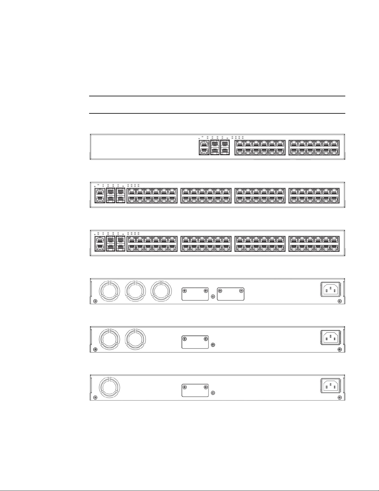
ICX 6450 models
NOTE
The ICX 6430-24P and ICX 6430-48P devices support up to 802.3at PoE+.
FIGURE 1 ICX 6430-48 and ICX 6430-48P front panels
FIGURE 2 ICX 6430-24P front panel
FIGURE 3 ICX 6430-24P front panel
FIGURE 4 ICX 6430-24P and ICX 6430-48P rear panels
FIGURE 5 ICX 6430-24P rear panel
FIGURE 6 ICX 6430-48 rear panel
ICX 6450 models
The ICX 6450 device is available in the following models:
• ICX 6450-24 — 24 10/100/1000 Mbps copper ports and 4 ports with 1 or 10 Gbps SFP+ fiber
uplink and stacking ports
• ICX 6450-24P — 24 10/100/1000 Mbps PoE+ copper ports and 4 ports with 1 or 10 Gbps SFP+
fiber uplink and stacking ports
12 Brocade ICX 6430 and ICX 6450 Stackable Switches Hardware Installation Guide
53-1003079-01
Page 15
ICX6430 and ICX 6450 Overview
• ICX 6450-48 — 48 10/100/1000 Mbps copper ports and 4 ports with 1 or 10 Gbps SFP+ fiber uplink
and stacking ports
• ICX 6450_48P — 48 10/100/1000 Mbps PoE+ copper ports and 4 ports with 1 or 10 Gbps SFP+
fiber uplink and stacking ports
NOTE
The ICX 6450-24P and ICX 6450_48P devices support up to 802.3 at PoE+.
FIGURE 7 ICX 6450-24 and ICX 6450-24P front panels
FIGURE 8 ICX 6450-48 front panel
FIGURE 9 ICX 6450_48P front panel
FIGURE 10 ICX 6450_48P rear panel
FIGURE 11 ICX 6450-24P rear panel
FIGURE 12 ICX 6450-24 and ICX 6450-48 rear panels
Brocade ICX 6430 and ICX 6450 Stackable Switches Hardware Installation Guide 13
53-1003079-01
Page 16
Network and management interfaces
Network and management interfaces
Each ICX 6430 and ICX 6450 includes the following management interfaces, and a system reset
button on the front panel of the device:
• Console management interface (RJ45 serial port)
• Out-of-band management interface (RJ45 port)
• Reset button
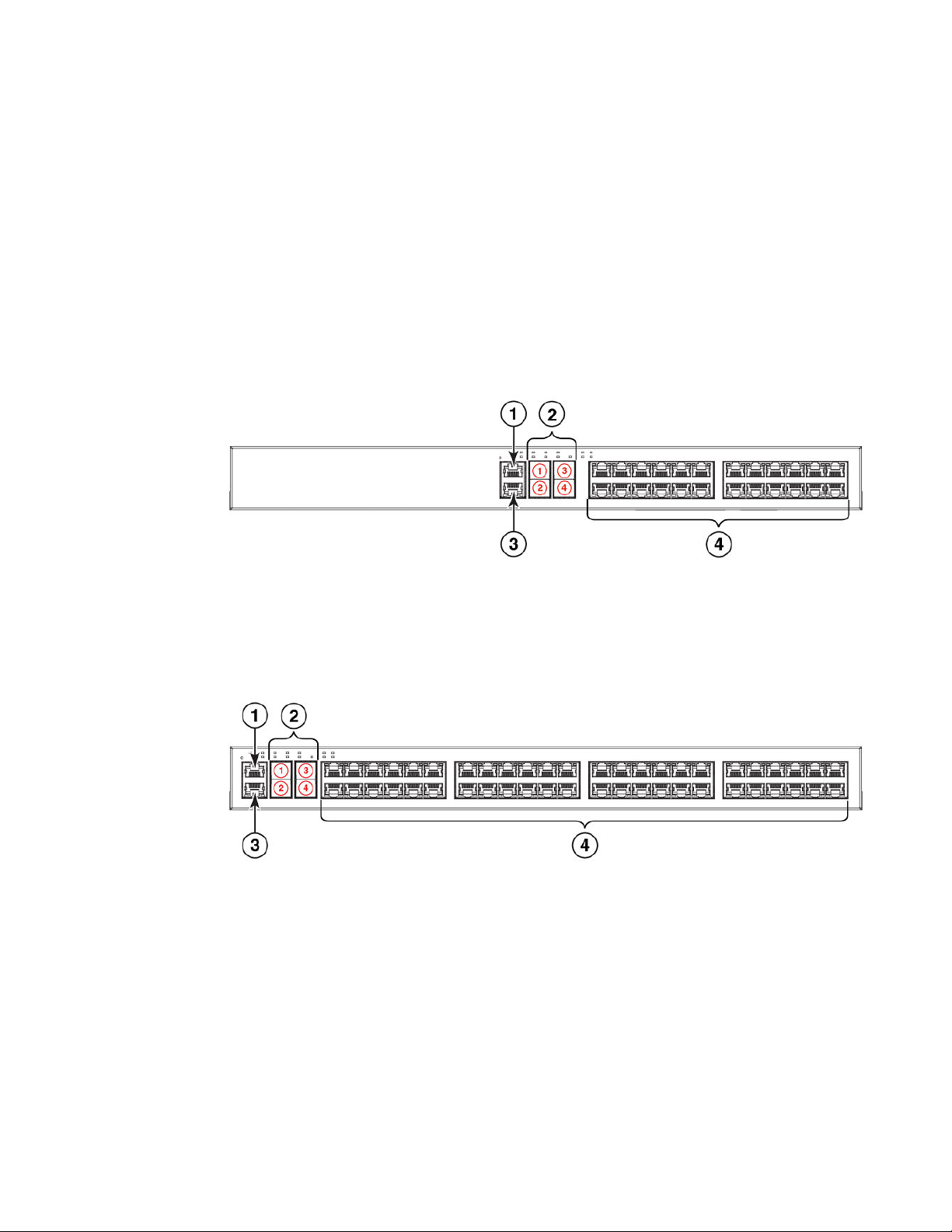
These RJ45 management ports are located together in the middle of the front panel on 24-port
models, and on the left side of the front panel on 48-port models.
FIGURE 13 Management interfaces and slot locations on 24-port models
1. Console port
2. Slot 2 (SFP and SFP + uplink or stacking ports)
3. Out-of-band management port
4. Slot 1 (10/100/1000 Mbps ports)
FIGURE 14 Management interfaces and slot locations on 48-port models
1. Console port
2. Slot 2 (SFP and SFP + uplink or stacking ports)
3. Out-of-band management port
4. Slot 1 (10/100/1000 Mbps ports
Console management interface
The console management interface is an RJ45 serial port that allows you to configure and manage the
device using a third-party terminal emulation application from a directly connected PC.
14 Brocade ICX 6430 and ICX 6450 Stackable Switches Hardware Installation Guide
53-1003079-01
Page 17

Out-of-band management interface
Out-of-band management interface
The out-of-band management interface is an RJ45 port that allows you to configure and manage the
device from the network.
System reset button
The reset button allows you to restart the system without switching the power supply off and on, using
the CLI. When the reset button is pressed, the system resets and the software is reloaded. The button
is located to the left of the console management interface.
Network interfaces for ICX 6430 and ICX 6450 devices
ICX 6430 and ICX 6450 devices contain the following interfaces:
• 10/100/1000 Mbps ports with RJ45 copper connectors.
• SFP/SFP+ ports.
SFP ports support 1 Gbps port speeds. SFP+ ports support 10 Gbps port speeds.
NOTE
ICX 6430 models support SFP ports only. ICX 6450 models support both SFP or SFP+ ports.
Slot designations
Refer to Network and management interfaces on page 14 for the location of slot 1 and slot 2 on the
front panel of the 24-port models and the 48-port models.
Slot designations for ICX 6430 and ICX 6450 devices TABLE 1
Device Slot 1 (10/100/1000 BASE-T ports) Slot 2 (SFP and SFP +ports)
ICX 6430-24 10/100/1000 Mbps ports 1-24 SFP ports 1-4
ICX 6430-24P 10/100/1000 Mbps ports 1-24 SFP ports 1-4
ICX 6430-48 10/100/1000 Mbps ports 1-48 SFP ports 1-4
ICX 6430-48P 10/100/1000 Mbps ports 1-48 SFP ports 1-4
ICX 6450-24 10/100/1000 Mbps ports 1-24 SFP and SFP+ ports 1-4
ICX 6450-24P 10/100/1000 Mbps ports 1-24 SFP and SFP+ ports 1-4
ICX 6450-48 10/100/1000 Mbps ports 1-48 SFP and SFP+ ports 1-4
ICX 6450_48P 10/100/1000 Mbps ports 1-48 SFP and SFP+ ports 1-4
Brocade ICX 6430 and ICX 6450 Stackable Switches Hardware Installation Guide 15
53-1003079-01
Page 18

10/100/1000 BASE-T ports
10/100/1000 BASE-T ports
All ICX 6430 and ICX 6450 devices provide 24 or 48 RJ45 ports that operate at 10 Mbps or 100 Mbps
half or full duplex, or at 1000 Mbps full duplex. Because all ports support automatic MDI or MDI-X
operation, you can use straight-through cables for all network connections to PCs, servers, or other
devices or hubs. In addition, it is ideal (and preferred) to use straight-through cables for switch-toswitch connections.
Each port supports auto-negotiation, so the optimum transmission mode (half or full duplex), and the
data rate (10, 100, or 1000 Mbps) can be selected automatically. If a device connected to one of these
ports does not support auto-negotiation, the communication mode of the port can be configured
manually.
SFP or SFP+ fiber ports
ICX 6430 and ICX 6450 devices contain four small form factor pluggable (SFP) ports (ports 1 through
4). The top row consists of ports 1 and 3, and the bottom row consists of ports 2 and 4. These ports
reside on Slot 2 of the stackable switch and can be used as uplink (data) ports or stacking ports.
The ICX 6430 contains SFP ports that support 1 Gbps port speeds but do not support 10 Gbps port
speeds. The ICX 6450 contains SFP+ ports that support 1 Gbps or 10 Gbps port speeds.
Ports 1 and 3 are default stacking ports. Default stacking ports are enabled to accept special stacking
packets during a CLI-initiated command sequence of the Secure Setup utility. If ports 1 and 3 are not
used as stacking ports, you can use them as data ports. Configuration is not required to use them as
data ports.
On the ICX 6450, ports 1 and 3 are 10 Gbps ports. Without a license at bootup, ICX 6450 ports 2 and
4 come up in 10 Gbps port speed in an error disabled state. To enable ports 2 and 4 to 10 Gbps port
speed, purchase the ICX6450-2X10G-LIC-POD license. For more information about enabling ports 2
and 4 to 10 Gbps port speed, refer to the FastIron Ethernet Switch Administration Guide. The
ICX6450-10G-LIC-POD license is not applicable toICX 6430 devices because there are no 10 Gbps
ports on the device.
For information about supported SFP and SFP+ transceivers, refer to the following Brocade website:
http://www.brocade.com/downloads/documents/data_sheets/product_data_sheets/Optics_DS.pdf
Specifying a port address
You can specify a port address for an uplink (data) port, stacking port, or a management port.
Specifying a data port
The port address format is stack unit/slot/port , where:
• stack unit --Specifies the stack unit ID. For the ICX 6430, range is from 1 to 4. For the ICX 6450,
range is from 1 to 8. If the device is not part of a stack, the stack unit ID is 1.
• slot --Specifies the slot number. Can be 1 or 2.
• port --Specifies the port number in the slot. Range is from 1 to 24 (24-port models) or 1 to 48 (48port models).
This example shows how to specify port 2 in slot 1 of a device that is not part of a stack:
Brocade (config) # interface ethernet 1/1/2
16 Brocade ICX 6430 and ICX 6450 Stackable Switches Hardware Installation Guide
53-1003079-01
Page 19
Specifying a stacking port
Specifying a stacking port
The port address format is stack unit/slot/port , where:
• stack unit --Specifies the stack unit ID. For the ICX 6430, range is from 1 to 4. For the ICX 6450,
range is from 1 to 8.
• slot --Specifies the slot number. Stacking ports are in slot 2.
• port --Specifies the port number in the slot. Stacking ports are 1, 2, 3, and 4.
This example shows how to specify stacking port 3 in slot 2 of unit 3 in a stack:
Brocade (config) # interface ethernet 3/2/3
Specifying a management port
The management port number is always 1. This example shows how to specify the management port:
Brocade (config) # interface management 1
Port, system, and power status LEDs
ICX 6430 and ICX 6450 devices include LEDs that indicate the status of device components.
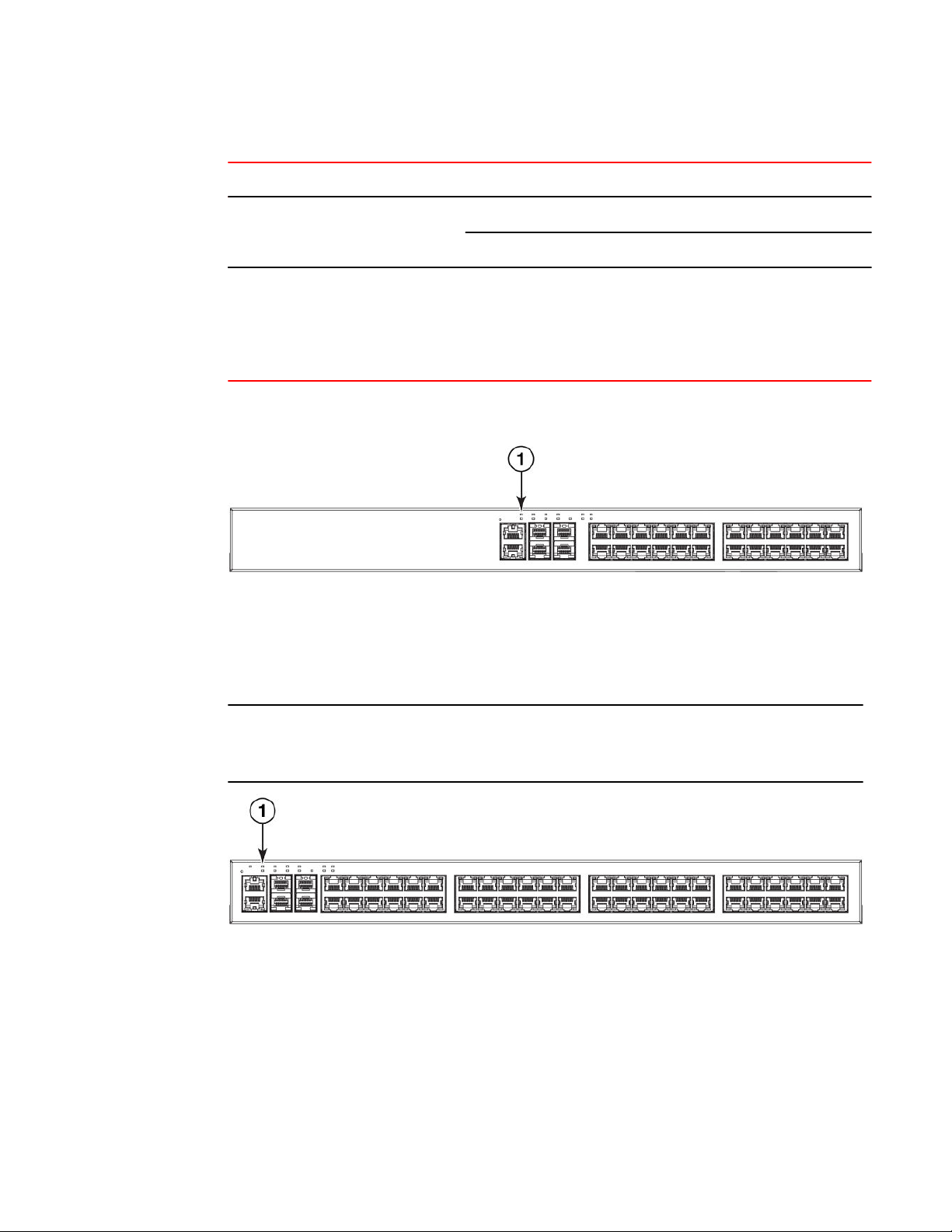
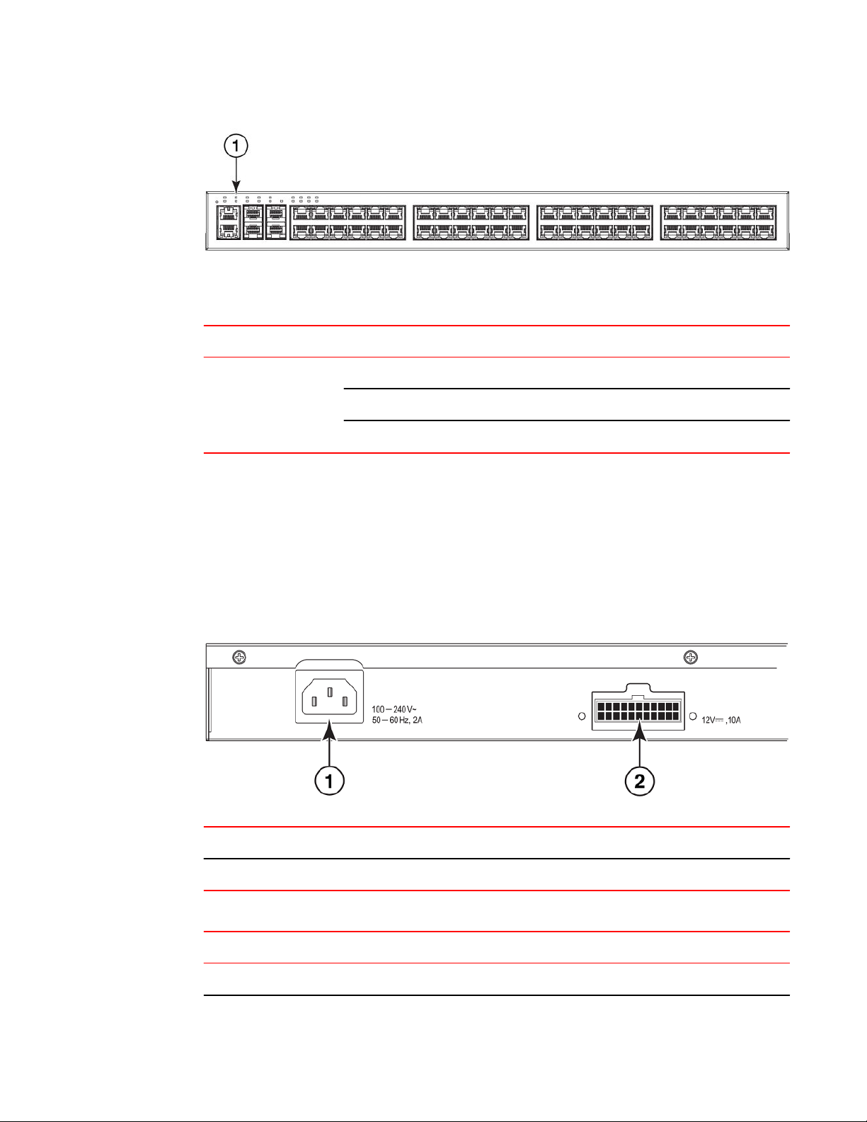
Port status LEDs
1
FIGURE 15 Port status LEDs on 24-port models
Port status LEDs
1
2 Port status LEDs
FIGURE 16 Port status LEDs on 48-port models
Brocade ICX 6430 and ICX 6450 Stackable Switches Hardware Installation Guide 17
53-1003079-01
Page 20

ICX6430 and ICX 6450 Overview
LED Condition Status
Port status LEDs TABLE 2
Ethernet
(1 - 24/48)
PoE/PoE+(1~24/48) On/Green The port is providing PoE or PoE+ power to a
SFP/SFP+(X1 - X4) for ICX 6450
devices
SFP(F1 - F4) for ICX 6430 devices On/ Flashing Green The SFP port is operating at 1 Gbps. Flashing
Out-of-band management port (2
LEDs)
On/Flashing Green The port has established a valid link at 10, 100 or
1000 Mbps. Flashing indicates the port is
transmitting and receiving user packets.
Off A link is not established with a remote port.
connected device.
Off The port is not providing PoE or PoE+ power.
On/Flashing Green The SFP port is operating at 10 Gbps. Flashing
indicates the port is transmitting and receiving user
packets at 10 Gbps.
On/Flashing Yellow The SFP port is operating at 1 Gbps. Flashing
indicates the port is transmitting and receiving user
packets at 1 Gbps.
Off A link is not established with a remote port.
indicates the port is transmitting and receiving user
packets at 1 Gbps.
Off A link is not established with a remote port.
Off (both LEDs) Offline
On/Flashing (left side) Link-up. Flashing indicates the port is transmitting
and receiving user packets.
On/Green (right side) 1 Gbps Link-up
Right LED off, left LED
on or flashing
18 Brocade ICX 6430 and ICX 6450 Stackable Switches Hardware Installation Guide
10/100 Mbps Link-up. Flashing indicates the port is
transmitting and receiving user packets.
53-1003079-01
Page 21
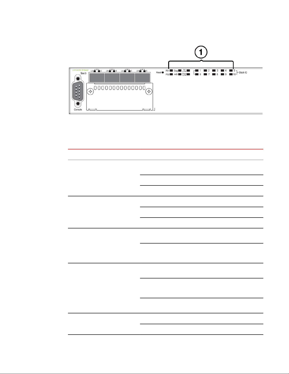
1 System status LEDs
FIGURE 17 System status LEDs on ICX 6430-48P 48-port model
System status LEDs on ICX 6450 and ICX 6430 devices TABLE 3
ICX6430 and ICX 6450 Overview
LED Condition Status
EPS1 and EPS2
(External Power Supply status for ICX
6450_48P devices only)
PWR
(Power)
Diag
(Diagnostic)
MS
(Stacking configuration)
Green EPS1 and EPS2 power supplies are operating
normally.
Yellow EPS1 and EPS2 power supply fault.
Off EPS1 and EPS2 off or not present.
Green Power supply is operating normally.
Yellow Power supply fault.
Off Power supply off.
Flashing Green System self-diagnostic test in progress. System
reloads automatically.
Steady Yellow System self-diagnostic test has detected a fault. (Fan,
thermal, or any interface fault.) The user must reload
the system.
Green The device is the Active controller. Flashing indicates
the system is initializing.
Yellow Indicates the device is the Standby controller. Flashing
indicates the system is in Master arbitration or
selection state.
Off Device is operating as a stack member, or is in
Uplink (X1 and X2)
(Stacking port status)
Brocade ICX 6430 and ICX 6450 Stackable Switches Hardware Installation Guide 19
53-1003079-01
Green Uplink port is operating normally.
Off Uplink has failed or there is no link.
standalone mode.
Page 22
ICX6430 and ICX 6450 Overview
LED Condition Status
System status LEDs on ICX 6450 and ICX 6430 devices (Continued)TABLE 3
Downlink (X3 and X4)
(Stacking port status)
1-8
(Switch ID in the stack)
Green Downlink port is operating normally.
Off Downlink has failed or there is no link.
Green Indicates the switch ID in the stack.
For ICX 6430 devices, 1 - 4 indicates the switch ID in
the stack.
For ICX 6450 devices, 1 - 8 indicates the switch ID in
the stack.
The following three figures show the location of the system status LEDs on the 24-port models and 48port models.
1 Power status LEDs
FIGURE 18 Power status LED on the ICX 6430-24 model
Power status LED on the ICX 6430-48 and ICX 6430-48P models
NOTE
The location of the power status LED on the front panel of the ICX 6430-48 and ICX 6430-48P devices
is the same on the ICX 6430-24P device, ICX 6450-24 device, ICX 6450-24P device, and the ICX
6450-48 device.
Power status LEDs
1
FIGURE 19 Power status LED on the ICX 6450_48P model
20 Brocade ICX 6430 and ICX 6450 Stackable Switches Hardware Installation Guide
53-1003079-01
Page 23
1 Power status LEDs
Power status LED on ICX 6430 and ICX 6450 devicesTABLE 4
LED Condition Status
Internal power status Off No input power
Green (steady) Internal Power Supply Unit (PSU) is working normally
Yellow (steady) Internal PSU failed, power is provided by EPS.
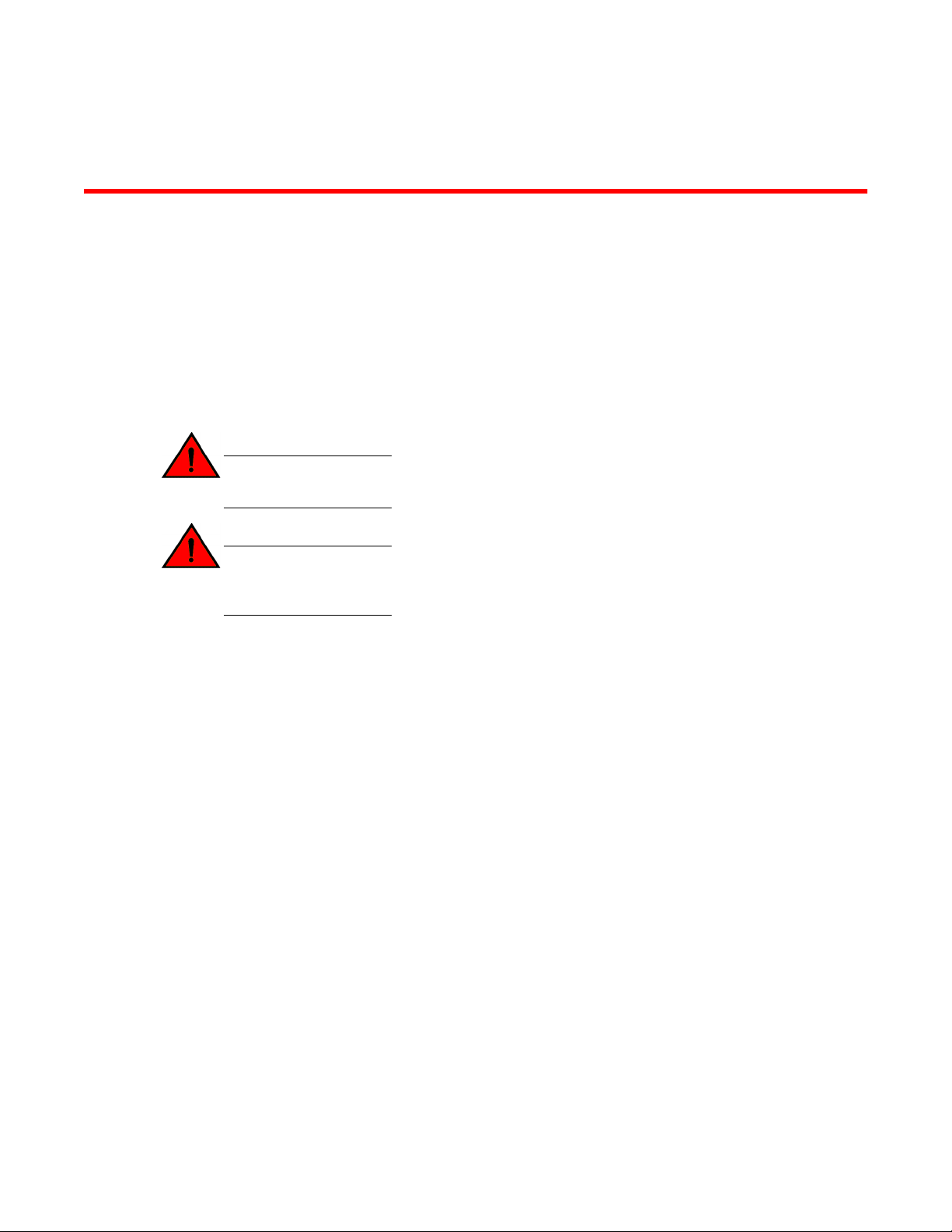
Power supplies
Power supplies
ICX 6430 and ICX 6450 devices have one standard power supply receptacle on the rear panel of the
device for the AC power cord. The connector labeled "EPS" is for the optional external power supply
cord that can provide power to the device in the event the internal power supply fails.
FIGURE 20 ICX 6430-48 power supply connectors
1
2 External power supply (EPS) connector
AC power supply socket
EPS connectors on the ICX 6430 and ICX 6450 modelsTABLE 5
Model EPS connectors
ICX 6430-24 0
Brocade ICX 6430 and ICX 6450 Stackable Switches Hardware Installation Guide 21
53-1003079-01
Page 24

Power supply usage
EPS connectors on the ICX 6430 and ICX 6450 models (Continued)TABLE 5
Model EPS connectors
ICX 6430-24P 1
ICX 6430-48 1
ICX 6430-48P 1
ICX 6450-24 1
ICX 6450-24P 1
ICX 6450-48 1
ICX 6450_48P 2
Power supply usage
The ICX 6430 and ICX 6450 models support specific AC power supply inputs and numbers of POE
and POE+ ports with internal power supply.
NOTE
Each EPS connection from the device to the ICX 6400-EPS1500 can add 24 ports of PoE or 12 ports
of PoE+ power in addition to the internal power supply by providing system power backup. The system
power portion of the EPS can be used for internal system power redundancy.
AC power supply and POE and POE+ usageTABLE 6
Model Maximum Power Draw from
AC line input (Watts)
ICX 6430-24 23.01 Watts 0 0
ICX 6430-24P 471.1 Watts 24 PoE ports 12 PoE+ ports
ICX 6430-48 45.01 Watts 0 0
ICX 6430-48P 484.6 Watts 24 PoE ports 12 PoE+ ports
ICX 6450-24 44.4 Watts 0 0
ICX 6450-24P 481.3 Watts 24 PoE ports 12 PoE+ ports
The number of PoE ports
supported with internal
power supply
The number of PoE+ ports
supported with internal power
supply
ICX 6450-48 65.6 Watts 0 0
ICX 6450_48P 912.4 Watts 48 PoE ports 24 PoE+ ports
22 Brocade ICX 6430 and ICX 6450 Stackable Switches Hardware Installation Guide
53-1003079-01
Page 25
ICX 6430 and ICX 6450 Installation
● Items included with the ICX 6430 and ICX 6450 devices............................................... 23
● Configuration requirements.............................................................................................23
● Summary of installation tasks......................................................................................... 24
● Installation precautions................................................................................................... 24
● Preparing the installation site.......................................................................................... 26
● Installing the device.........................................................................................................26
● Connecting devices in a traditional stack........................................................................ 31
● Connecting devices in a mixed stack.............................................................................. 35
● Powering on the system..................................................................................................45
DANGER
The procedures in this manual are intended for qualified service personnel.
DANGER
Before beginning the installation, see the precautions in the “Power_precautions” section under
the “Installation precautions” section in this chapter.
Items included with the ICX 6430 and ICX 6450 devices
ICX 6430 and ICX 6450 devices ship with all of the following items included in your shipping container.
Verify the contents of your shipping container. If any items are missing, contact the place of purchase.
• ICX 6430 or ICX 6450 device
• Rack mounting kit containing two L-shaped mounting brackets and six sink-head screws
• Wall mounting kit containing two wall-mount screws and two plastic anchors (for ICX 6430-24, ICX
6430-24P, ICX 6450-24, and ICX 6450-24P devices only)
• Two-post rack kit containing four rack-mounting screws and four cage nuts
• One AC power cord - US only
• Power cord retainer clip
• Console cable
• Four rubber feet
• China ROHS sheet
• Read Me First document
Configuration requirements
To manage theICX 6430 or ICX 6450, you need a management station, such as a PC running a
terminal emulation application, for serial connection to the device.
Brocade ICX 6430 and ICX 6450 Stackable Switches Hardware Installation Guide
53-1003079-01
23
Page 26
Summary of installation tasks
Use the serial connection to perform basic configuration tasks, including assigning an IP address and
network mask to the system. This information is required to manage the system using the CLI through
Telnet or the Brocade Network Advisor.
Summary of installation tasks
Follow the steps listed below to install your device. Details for each of these steps are provided on the
pages indicated.
Installation tasks TABLE 7
Task number Task Where to find more information
1 Ensure that the physical environment that will host the
device has the proper cabling and ventilation.
2 Unpack the device and all included accessories, Items included with the ICX 6430 and
3 Install the device on a desktop, or in an equipment
rack.
4 Once the device is installed, plug the device into a
nearby power source that adheres to the regulatory
requirements outlined in this manual.
Installation precautions
Follow all precautions when installing a device.
General precautions
DANGER
All fiber-optic interfaces use Class 1 lasers.
Preparing the installation site on page
26
ICX 6450 devices on page 23
Installing the device on page 26
Powering on the system on page 45
CAUTION
Do not install the device in an environment where the operating ambient temperature might
exceed 40 ο C (104 ο F).
CAUTION
Make sure the airflow around the front, sides, and back of the device is not restricted.
24 Brocade ICX 6430 and ICX 6450 Stackable Switches Hardware Installation Guide
53-1003079-01
Page 27
Lifting precautions
CAUTION
Never leave tools inside the device.
Lifting precautions
DANGER
Make sure the rack or cabinet housing the device is adequately secured to prevent it from
becoming unstable or falling over.
DANGER
Mount the devices you install in a rack or cabinet as low as possible. Place the heaviest device
at the bottom and progressively place lighter devices above.
Power precautions
CAUTION
Ensure that the device does not overload the power circuits, wiring, and over-current protection.
To determine the possibility of overloading the supply circuits, add the ampere (amp) ratings of
all devices installed on the same circuit as the device. Compare this total with the rating limit for
the circuit. The maximum ampere ratings are usually printed on the devices near the input
power connectors.
DANGER
Disconnect the power cord from all power sources to completely remove power from the device.
CAUTION
Before plugging a cable to any port, be sure to discharge any static charge stored on the cable
by touching the electrical contacts to ground surface.
DANGER
If the installation requires a different power cord than the one supplied with the device, make
sure you use a power cord displaying the mark of the safety agency that defines the regulations
for power cords in your country. The mark is your assurance that the power cord can be used
safely with the device.
Brocade ICX 6430 and ICX 6450 Stackable Switches Hardware Installation Guide 25
53-1003079-01
Page 28

Preparing the installation site
Preparing the installation site
Before installing the device, plan its location and orientation relative to other devices and equipment.
Cabling infrastructure
Ensure that the proper cabling is installed at the site. For information about supported SFP and SFP+
transceivers and cable lengths and types, refer to the following Brocade website: http://
www.brocade.com/downloads/documents/data_sheets/product_data_sheets/Optics_DS.pdf
Installation location
Devices can be mounted in a standard 19-inch equipment rack or on a flat surface.
The site should meet the following requirements:
• Maintain the operating environment as specified in the section Environmental considerations on
page 89.
• Allow a minimum of 7.62 cm (3 in.) of space between the front and the back of the device and
walls or other obstructions for proper airflow.
• Allow at least 7.62 cm (3 in.) of space at the front and back of the device for the twisted-pair, fiberoptic, and power cabling.
• The site should be accessible for installing, cabling and maintaining the devices.
• Allow the status LEDs to be clearly visible.
• Allow for twisted-pair cables to be routed away from power lines, fluorescent lighting fixtures, and
other sources of electrical interference, such as radios and transmitters.
• Allow for the unit to be connected to a separate grounded power outlet that provides 100 to 240
VAC, 50 to 60 Hz, is within 2 m (6.6 ft) of each device, and is powered from an independent circuit
breaker. As with any equipment, a filter or surge suppressor is recommended.
• Some combinations of intake and exhaust airflows may not be compatible with your environment.
• For a 2-post rail mount configuration, order the appropriate mounting kit and refer to the kit
documentation.
Rack-mount installation considerations
Before mounting the device in a rack, ensure that the following rack-mount installation requirements
are met:
• Temperature: Because the temperature within a rack assembly may be higher than the ambient
room temperature, check that the rack-environment temperature is within the specified operating
temperature range. (Refer to Operating environment on page 89.)
• Mechanical loading: Do not place any equipment on top of a rack-mounted unit.
• Circuit overloading: Be sure that the supply circuit to the rack assembly is not overloaded.
• Grounding: Rack-mounted equipment should be properly grounded.
Installing the device
You can install the device on a desktop or in an equipment rack.
26 Brocade ICX 6430 and ICX 6450 Stackable Switches Hardware Installation Guide
53-1003079-01
Page 29
Desktop installation
DANGER
Mount the devices you install in a rack or cabinet as low as possible. Place the heaviest device
at the bottom and progressively place lighter devices above.
Desktop installation
Complete the following steps to install the ICX 6430 or ICX 6450 device on a desktop or other flat
surface.
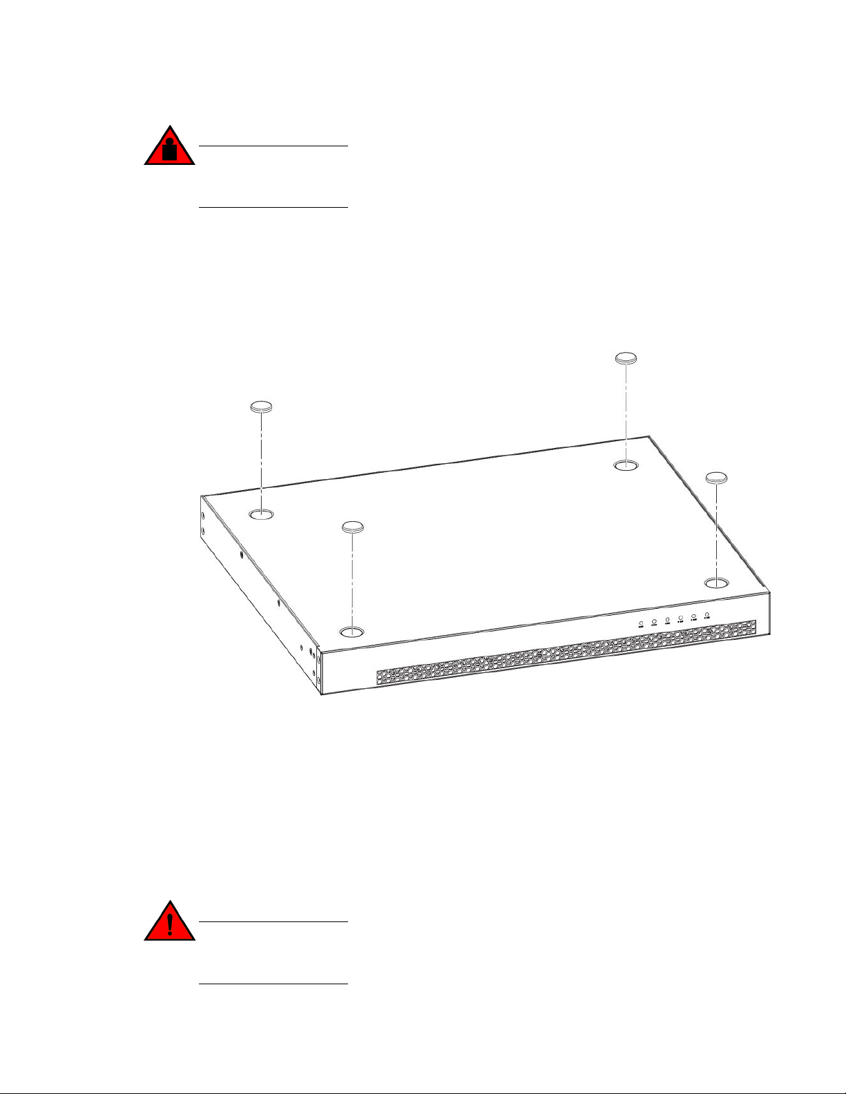
FIGURE 21 Attaching the adhesive feet
1. Attach the four adhesive feet to the bottom of the device.
2. Set the device on a flat desktop, table, or shelf near an AC power source. Make sure that adequate
ventilation is provided for the system. A 7.62 cm (3-inch) clearance is recommended on each side.
3. If installing a single device only, go to the “Powering on the system” task. Place each device
squarely on top of the one below.
4. If installing multiple devices, attach the adhesive feet to each device.
Rack mount installation
The devices use stationary mounting when mounted in a rack.
DANGER
Make sure the rack or cabinet housing the device is adequately secured to prevent it from
becoming unstable or falling over.
Brocade ICX 6430 and ICX 6450 Stackable Switches Hardware Installation Guide 27
53-1003079-01
Page 30
ICX 6430 and ICX 6450 Installation
NOTE
You need a #2 Phillips screwdriver for rack mount installation.
Complete the following steps to mount devices in rack.
1. Remove the rack mount kit from the shipping carton. The kit contains two L-shaped mounting
brackets and six sink-head screws.
2. Using a Phillips screwdriver, attach the mounting brackets to the sides of the device using six
sink-head screws.
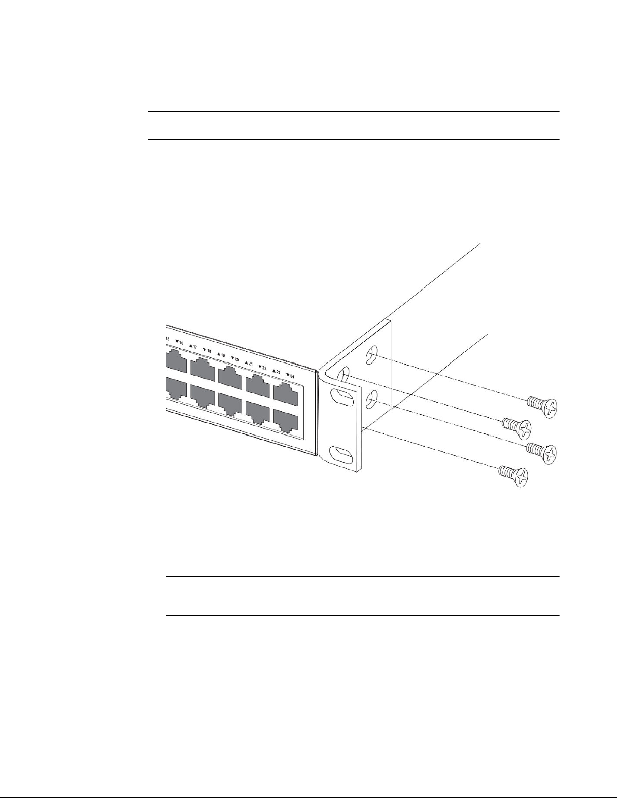
FIGURE 22 Attaching the mounting brackets for ICX 6430 and ICX 6450 devices
3. Remove the two-post rack kit from the shipping carton. The kit contains four rack-mounting
screws and four cage nuts.
4. Insert the cage nuts in the two-post rack where you want to mount the device.
5. Using a Phillips screwdriver, mount the device in a two-post rack using four rack-mounting
screws.
NOTE
The ICX 6430 and ICX 6450 devices must be installed on 2-post racks only. The devices cannot
be installed on 4-post racks.
28 Brocade ICX 6430 and ICX 6450 Stackable Switches Hardware Installation Guide
53-1003079-01
Page 31

Wall mount installation
1 Rack-mounting screws
2 Cage nuts
FIGURE 23 Installing the device in a two-post rack
6. If installing a single device only, proceed to “Powering on the system.” If installing multiple devices,
mount them in the rack, one below the other.
Wall mount installation
NOTE
You need a #2 Phillips screwdriver, a hammer, and a drill for wall mount installation.
Mounting the device to a wall is only applicable to ICX 6430-24, ICX 6430-24P, ICX 6450-24, and ICX
6450-24P devices. Brocade recommends that you wall mount the device with the port side down.
NOTE
The ICX 6430-48, ICX 6430-48P, ICX 6450-48, and ICX 6450_48P devices cannot be wall mounted.
Complete the following steps to mount the device to a wall.
Brocade ICX 6430 and ICX 6450 Stackable Switches Hardware Installation Guide 29
53-1003079-01
Page 32

ICX 6430 and ICX 6450 Installation
1. Attach the four adhesive feet to the bottom of the device.
2. Using a Phillips screwdriver, attach the wall mount brackets to the sides of the device using four
sink-head screws.
FIGURE 24 Attaching the wall mount brackets for ICX 6430-24 devices
3.
Drill two holes on the wall where you want to mount the device.
4. Hammer two wall mount anchors into the holes on the wall.
5. Use the two wall mount screws to fasten the device to the wall mount anchors.
30 Brocade ICX 6430 and ICX 6450 Stackable Switches Hardware Installation Guide
53-1003079-01
Page 33

Connecting devices in a traditional stack
1 Drilled holes
2 Wall mount anchors
3 Wall mount screws
FIGURE 25 Wall mounting the ICX 6430-24P device
Connecting devices in a traditional stack
ICX 6430 devices and ICX 6450 devices can operate as standalone devices and also as members of
traditional stacks. A stack is a group of devices—Brocade stackable units and their connected stacking
links—that are connected so that the stack is managed as a single entity.
A traditional stack contains devices from only one model in a product family: only ICX 6430 devices or
only ICX 6450 devices. A traditional stack cannot contain both ICX 6430 devices and ICX 6450 devices.
Brocade ICX 6430 and ICX 6450 Stackable Switches Hardware Installation Guide 31
53-1003079-01
Page 34

Stacking ports and trunks
Stacking ports and trunks
There are four SFP ports (ICX 6430) or four SFP+ ports (ICX 6450) on the front panels that can be
used as uplink (data) ports or as stacking ports. The figure below shows the ports in slot 2; the top row
consists of ports 1 and 3, and the bottom row consists of ports 2 and 4.
FIGURE 26 Stacking ports
1. Console port
2. Slot 2 (SFP and SFP + uplink or stacking ports)
3. Out-of-band management port
4. Slot 1 (10/100/1000 Mbps ports)
Ports 1 and 3 are default stacking ports. Default stacking ports have the capability to accept special
stacking packets during a CLI-initiated command sequence of the Secure Setup utility. If ports 1 and 3
are not used as stacking ports, you can use them as data ports. Configuration is not required to use
them as data ports.
All four ports in slot 2 can be used as stacking ports.
The stacking ports can be grouped into two trunks. Ports 1 and 2 can form a trunk; ports 3 and 4 can
form another trunk. By default, ICX 6430 and ICX 6450 devices are not configured for trunking.
On the ICX 6450, ports 1 and 3 are 10 Gbps ports. Without a license at bootup, ICX 6450 ports 2 and
4 come up in 10 Gbps port speed in an error disabled state. To enable ports 2 and 4 to 10 Gbps port
speed, purchase the ICX6450-2X10G-LIC-POD license. For more information about enabling ports 2
and 4 to 10 Gbps port speed, refer to the FastIron Ethernet Switch Administration Guide.
Trunking requirements
• You can connect one or both ports in a trunk. Connecting both ports in a trunk increases stacking
bandwidth and provides resiliency.
• If you connect both ports in a trunk, both ports must connect to both ports of one trunk on another
device.
• When configuring a trunk, the ports in the same column are always trunked (port 1 to port 2, port
3 to port 4). One or both of the two sets of stacking ports can be trunked (or un-trunked).
• For ICX 6430 devices, all stacking ports must be at 1-Gbps port speed to enable trunking. For ICX
6450 devices, all stacking ports must be configured to 10-Gbps port speed to enable trunking.
Stacking configuration requirements
Before configuring the traditional stack using the CLI, physically connect the devices using stacking
cables. For information about configuring a stack, see the FastIron Ethernet Switch Stacking
Configuration Guide.
32 Brocade ICX 6430 and ICX 6450 Stackable Switches Hardware Installation Guide
53-1003079-01
Page 35

Stacking cables
Stacking cables
Use copper stacking cables or SFP+ fiber optic cables to connect ICX 6450 devices or ICX 6430
devices in a traditional stack. The active copper cable lengths for 1-Gbps ports are 1 meter and 5
meters. The copper cable lengths for 10-Gbps ports are 1 meter, 3 meters, and 5 meters.
Stack size
A traditional stack can contain a maximum of eight ICX 6450 devices or four ICX 6430 devices. A
traditional stack cannot contain both ICX 6430 and ICX 6450 devices.
Stacking topologies
Both linear and ring topologies are supported in a traditional stack. In a linear stack topology there is a
connection between each switch that carries two-way communications across the stack. This
connection can use one port or two ports per trunk.
For example, in a four-unit stack using a linear topology, unit 1 connects to unit 2, unit 2 to unit 3, and
unit 3 to unit 4.
In ring stack topology, there is an extra connection between the logical first and last devices forming
a"ring" or "closed-loop." The closed-loop connection provides a redundant path for the stack link, so if
one link fails, stack communications can be maintained.
For example, in a four-unit stack using a ring topology, unit 1 connects to unit 2, unit 2 to unit 3, unit 3 to
unit 4, and unit 4 connects to unit 1.
You can connect stacking units using one port per trunk or both ports in a trunk. For maximum
bandwidth and link redundancy, use both ports per trunk.
The following figures show supported stacking topologies:
Brocade ICX 6430 and ICX 6450 Stackable Switches Hardware Installation Guide 33
53-1003079-01
Page 36

ICX 6430 and ICX 6450 Installation
• Linear and ring stacking topologies using one port per trunk. (the most commonly configured
stacking topology.)
• Linear stacking topology using both ports in each trunk.
• Ring stacking topology using both ports in each trunk.
FIGURE 27 Linear and ring stacking topologies using one port per trunk
FIGURE 28 Linear stacking topology using both ports in each trunk
34 Brocade ICX 6430 and ICX 6450 Stackable Switches Hardware Installation Guide
53-1003079-01
Page 37

FIGURE 29 Ring stacking topology using both ports in each trunk
Connecting devices in a mixed stack
Connecting devices in a mixed stack
ICX 6450 devices can operate as standalone devices and also as members of a mixed stack. A stack is
a group of devices--Brocade stackable units and their connected stacking links--that are connected so
that the stack is managed as a single entity.
A mixed stack contains ICX 6610 devices and ICX 6450 devices. ICX 6610 devices form the backbone
of the mixed stack. ICX 6450 devices are peripheral units that connect to the backbone and to other
peripheral units.
The table below summarizes the ports used in mixed stacking.
Brocade ICX 6430 and ICX 6450 Stackable Switches Hardware Installation Guide 35
53-1003079-01
Page 38

ICX 6610 stacking ports and trunks
Stacking ports used in mixed stackingTABLE 8
Device Stacking ports Panel/Slot Ports Speed Connection
Type
ICX 6610 Dedicated
stacking
ICX 6610 SFP+ Front/3 1-8 10 Gbps Backbone to
ICX 6450 SFP+ Front/2 1-4 10 Gbps Peripheral to
Rear/2 1, 6
2, 7
40 Gbps
4 x 10 Gbps
Backbone to
backbone: ICX
6610 to ICX
6610
peripheral: ICX
6610 to ICX
6450
backbone: ICX
6450 to ICX
6610
Peripheral to
peripheral: ICX
6450 to ICX
6450
ICX 6610 stacking ports and trunks
This section discusses the ports you can use to connect ICX 6610 devices in the backbone and to ICX
6450 devices.
Ports used to connect ICX 6610 devices in the backbone
The ICX 6610 device contains four ports in slot 2 on the rear panel that are dedicated stacking ports.
They cannot be used as data ports, even when stacking is not enabled. There are two 40 Gbps ports
and two 4 x 10 Gbps ports arranged in two rows.
The stacking ports can be grouped into two trunks. Ports 1 and 2 on the top row can form trunk 0;
ports 6 and 7 on the bottom row can form trunk 1.
You can trunk stacking ports by connecting one port of each type (40 Gbps or 4 x 10 Gbps) to ports of
the same type on another ICX 6610 device in the stack.
FIGURE 30 Dedicated stacking ports and trunks on the rear panel of an ICX 6610 device
1. Port 1, 40 Gbps
2. Trunk 0
3. Port 2, 4 x 10 Gbps
36 Brocade ICX 6430 and ICX 6450 Stackable Switches Hardware Installation Guide
53-1003079-01
Page 39

Trunking requirements
4. Port 6, 40 Gbps
5. Trunk 1
6. Port 7, 4 x 10 Gbps
Trunking requirements
• You can connect one or both ports in a trunk. Connecting both ports in a trunk increases stacking
bandwidth and provides resiliency.
• You must connect each port type (40 Gbps or 4x10 Gbps) to the same type of port on another
device, as shown in the table below.
Port connections for trunking between ICX 6610 devices TABLE 9
Valid port connections Invalid port connections
Device 1 Device 2 Device 1 Device 2
Port 1 to Port 1 Port 1 to Port 2
Port 1 to Port 6 Port 1 to Port 7
Port 2 to Port 2 Port 2 to Port 1
• If you connect both ports in a trunk, both ports must connect to both ports of one trunk on another
device.
NOTE
If you use the Secure Setup utility to set up a mixed stack, the stacking units (ICX 6610 devices and
ICX 6450 devices) are automatically trunked.
Ports used to connect ICX 6610 devices to ICX 6450 devices
There are eight SFP+ ports in slot 3 on the front panel of an ICX 6610 device that are used to connect
ICX 6610 devices to ICX 6450 devices in a mixed stack. The first figure below shows the 10 Gbps SFP+
ports in slot 3 of a 24-port device. The second figure below shows the 10 Gbps SFP+ ports in slot 3 of a
48-port device.
Without a license at bootup, the SFP+ ports come up in 10 Gbps port speed in an error-disabled state.
To enable the SFP+ ports to 10 Gbps port speed, you must purchase the ICX6610-10G-LIC-POD
license for each ICX 6610 SFP+ port that connects to an ICX 6450 device.
Maximum number of ports you can use on an ICX 6610 device to connect to ICX 6450 devices
Any one ICX 6610 device supports a maximum of:
Brocade ICX 6430 and ICX 6450 Stackable Switches Hardware Installation Guide 37
53-1003079-01
Page 40

ICX 6450 stacking ports and trunks
• Two trunk connections to ICX 6450 peripheral devices (four ports total).
• Two single (untrunked) port connections to ICX 6450 peripheral devices.
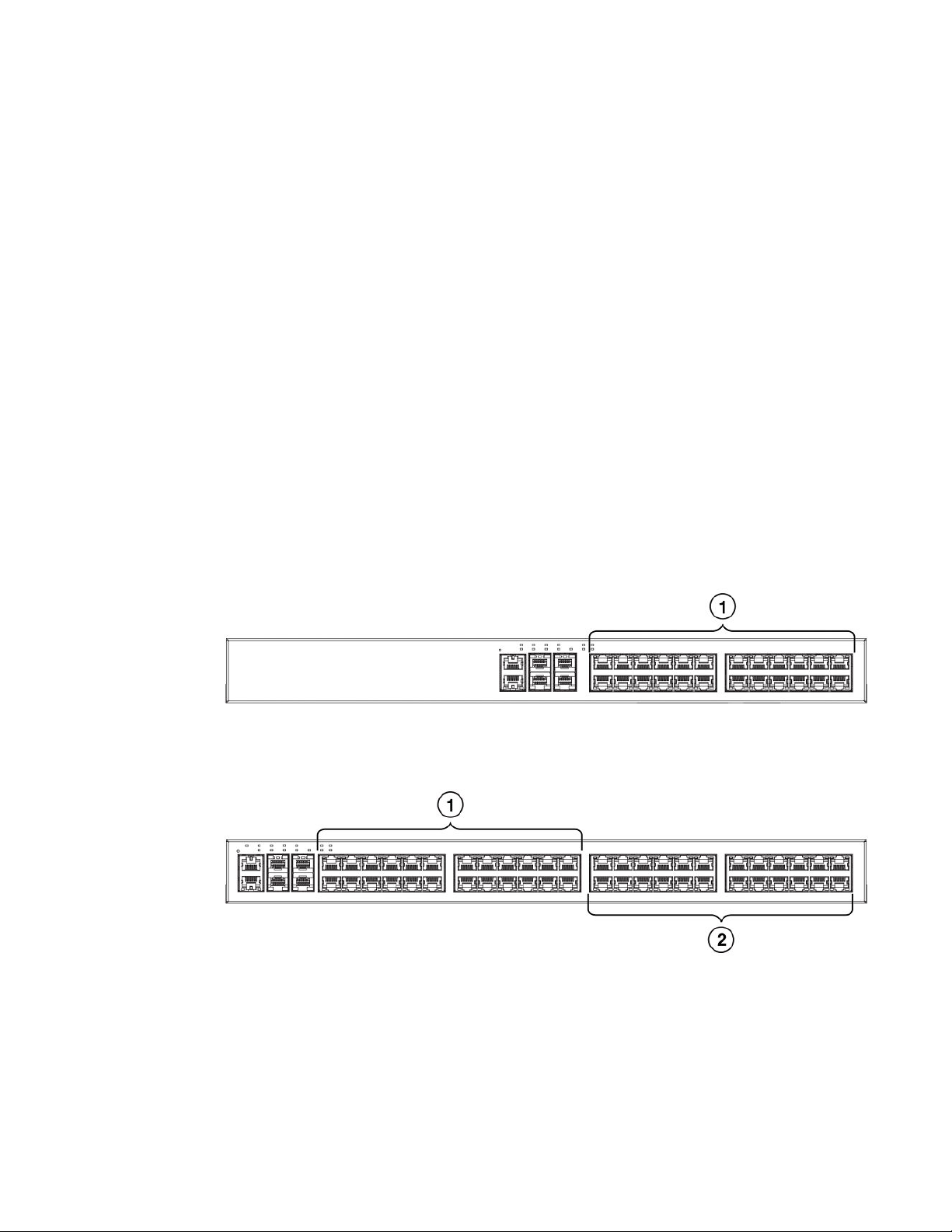
FIGURE 31 SFP+ ports on the front panel of the 24-port model of an ICX 6610 device
1. Slot 3: 10 Gbps SFP+ ports 1-8
2. Slot 1: 10/100/1000 Mbps ports
FIGURE 32 SFP+ ports on the front panel of the 48-port model of an ICX 6610 device
1. Slot 3: 10 Gbps SFP+ ports 1-8
2. Slot 1: 10/100/1000 Mbps ports
ICX 6450 stacking ports and trunks
The ICX 6450 contains four SFP+ ports in slot 2 on the front panel that can be used as uplink (data)
ports or as stacking ports. The figure below shows the ports in slot 2; the top row consists of ports 1
and 3, and the bottom row consists of ports 2 and 4.
FIGURE 33 Stacking ports on the front panel of an ICX 6450 device
1. Console port
2. Slot 2 (SFP and SFP + uplink or stacking ports)
3. Out-of-band management port
4. Slot 1 (10/100/1000 Mbps ports)
Ports 1 and 3 are default stacking ports. Default stacking ports have the capability to accept special
stacking packets during a CLI-initiated command sequence of the Secure Setup utility. If ports 1 and 3
are not used as stacking ports, you can use them as data ports. Configuration is not required to use
them as data ports.
38 Brocade ICX 6430 and ICX 6450 Stackable Switches Hardware Installation Guide
53-1003079-01
Page 41

Trunking requirements
All four ports in slot 2 can be used as stacking ports.
The stacking ports can be grouped into two trunks. Ports 1 and 2 can form a trunk; ports 3 and 4 can
form another trunk. By default, ICX 6450 devices are not configured for trunking.
On the ICX 6450, ports 1 and 3 are 10 Gbps ports. Without a license at bootup, ICX 6450 ports 2 and 4
come up in 10 Gbps port speed in an error disabled state. To enable ports 2 and 4 to 10 Gbps port
speed, you must purchase the ICX6450-2X10G-LIC-POD license. For more information about enabling
ports 2 and 4 to 10 Gbps port speed, refer to the FastIron Ethernet Switch Administration Guide.
Trunking requirements
• You can connect one or both ports in a trunk. Connecting both ports in a trunk increases stacking
bandwidth and provides resiliency.
• If you connect both ports in a trunk, both ports must connect to both ports of one trunk on another
device.
• When configuring a trunk, the ports in the same column are always trunked (port 1 to port 2, port 3
to port 4). One or both of the two sets of stacking ports can be trunked (or untrunked).
• For ICX 6450 devices, all stacking ports must be configured to 10 Gbps port speed to enable
trunking.
NOTE
If you use the Secure Setup utility to set up a mixed stack, the stacking units (ICX 6610 devices and
ICX 6450 devices) are automatically trunked.
Stacking configuration requirements
All configuration methods
Before configuring the mixed stack, physically connect the devices using stacking cables.
Secure Setup utility
To use the 10 Gbps SFP+ ports on the front panel of ICX 6610 devices to connect ICX 6610 devices to
ICX 6450 devices in a mixed stack, configure the SFP+ ports on the ICX 6610 devices to 10 Gbps using
the speed command.
Automatic and manual configuration methods
To connect an ICX 6610 device in the backbone to an ICX 6450 device (peripheral unit), configure the
peri-port command or peri-trunk command on the ICX 6610 device
For information about configuring a stack, see the FastIron Ethernet Switch Stacking Configuration
Guide.
Stacking cables
Brocade ICX 6430 and ICX 6450 Stackable Switches Hardware Installation Guide 39
53-1003079-01
Page 42

Stack size
Cables to connect devices in a mixed stack TABLE 10
To connect this device To this device Use this cable
ICX 6610 ICX 6610 1 meter passive copper QSFP stacking cable
100 meter QSFP fiber optic cable
ICX 6450 ICX 6450 SFP+ fiber optic cable
10 Gbps copper stacking cable
ICX 6610 ICX 6450 SFP+ fiber optic cable
10 Gbps copper stacking cable
Stack size
A mixed stack can contain one or two ICX 6610 devices. They form the backbone of the mixed stack.
ICX 6450 devices are peripheral units. There can be one to six ICX 6450 devices in a mixed stack.
Peripheral devices can form one or more substacks. A substack is a topology that is formed by ICX
6450 devices. If ICX 6450 devices are separated by an ICX 6610 device, the ICX 6450 devices belong
to different substacks.
Stacking topologies
Two basic ring topologies are supported in a mixed stack: single ring and dual ring.
In a linear stack topology there is a connection between each switch that carries two-way
communications across the stack. This connection can use one port or two ports per trunk.
In ring stack topology, there is an extra connection between the logical first and last devices forming
a"ring" or "closed-loop." The closed-loop connection provides a redundant path for the stack link, so if
one link fails, stack communications can be maintained.
For example, in a four-unit stack using a ring topology, unit 1 connects to unit 2, unit 2 to unit 3, unit 3
to unit 4, and unit 4 connects to unit 1.
You can connect stacking units using one port per trunk or both ports in a trunk. For maximum
bandwidth and link redundancy, use both ports per trunk on all stack units.
Topology 1: single ring
In the figure below, two ICX 6610 devices form the backbone and there are three ICX 6450 peripheral
devices. There can be up to six ICX 6450 peripheral devices.
40 Brocade ICX 6430 and ICX 6450 Stackable Switches Hardware Installation Guide
53-1003079-01
Page 43

Topology 2: dual ring
This is a single ring configuration in which the second ICX 6610 device is connected to the first ICX
6450 device, and the first ICX 6610 device is connected to the last ICX 6450 device. There is one
substack that contains three peripheral devices.
FIGURE 34 Topology 1: single ring
Topology 2: dual ring
In the figure below, two ICX 6610 devices form the backbone and there are six ICX 6450 peripheral
devices in two rings. This is a dual ring configuration.
The first ICX 6610 device is connected to the last ICX 6450 device in the "vertical" ring. The backbone
devices are also connected to the first and last ICX 6450 devices in the "horizontal" ring.
Brocade ICX 6430 and ICX 6450 Stackable Switches Hardware Installation Guide 41
53-1003079-01
Page 44

Topology 3: linear and ring
There are two substacks, each containing three peripheral devices.
FIGURE 35 Topology 2: dual ring
Topology 3: linear and ring
In the figure below, two ICX 6610 devices form the backbone and there are six ICX 6450 peripheral
devices in two substacks. Each substack contains three peripheral devices.
One substack is connected to one ICX 6610 device to form a linear topology. The other substack is
connected to each of the ICX 6610 devices to form a ring topology.
42 Brocade ICX 6430 and ICX 6450 Stackable Switches Hardware Installation Guide
53-1003079-01
Page 45

Topology 4: ring with one backbone device
Topology 3 is almost identical to topology 2 except that the "horizontal" substack is not connected to the
second ICX 6610 device either by design or because the link is broken. This is still a valid topology.
FIGURE 36 Topology 3: linear and ring
Topology 4: ring with one backbone device
In the figure below, one ICX 6610 device forms the backbone and there are six ICX 6450 peripheral
devices in a ring topology. There is one substack that contains all six peripheral devices.
Topology 4 shows that you can have a mixed stack with only one ICX 6610 device, although it does not
provide high availability or resiliency for the stack because there is no standby controller.
FIGURE 37 Topology 4: ring with one backbone device
Topology recommendations
Consider these factors when you implement a topology:
• Limit the number of VLANs of peripheral devices to reduce broadcast and multicast packets
flooding to the peripheral devices.
• Broadcast and multicast packets of a VLAN are flooded to a substack if the substack has any ports
in the VLAN. For this reason, you should limit (localize) VLAN association of substack ports.
For example, substacks 1 and 2 have ports in VLAN 10, 11, 12, and 13. In this case, you should
arrange the VLAN port association so that substack 1 ports are in VLAN 10, 11, and 12 and substack 2
Brocade ICX 6430 and ICX 6450 Stackable Switches Hardware Installation Guide 43
53-1003079-01
Page 46

Connecting ICX 6610 devices in the backbone
ports are in VLAN 12 and 13. Such an arrangement avoids flooding packets in VLAN 13 to substack 1,
and also avoids flooding packets in VLAN 10 and 11 to substack 2.
• A ring topology is more resilient than a linear topology.
• If there are two backbone devices, link substacks to both backbone devices.
• To prevent traffic congestion and avoid potential latency issues, keep substacks small -especially in linear topologies.
Connecting ICX 6610 devices in the backbone
The figure below shows how to connect ICX 6610 devices in a mixed stack backbone using both ports
(ports 1 and 2) in trunk 0 of each ICX 6610 device. Ports 1 and 2 in the top device connect to ports 1
and 2 in the bottom device, respectively.
FIGURE 38 Connecting ICX 6610 devices in the backbone
Connecting a peripheral device to an ICX 6610 and to another peripheral device
The figure below shows how to connect an ICX 6610 device in the backbone to an ICX 6450
peripheral device. It also shows how to connect two ICX 6450 peripheral devices to each other. Both
ports in each ICX 6450 trunk are used.
One trunk (ports 1 and 2) in the middle ICX 6450 device are used for the upstream link to the ICX
6610 device. The other trunk (ports 3 and 4) in the middle ICX 6450 device is used for the downstream
link to the second ICX 6450 device.
The ports or trunk on an ICX 6610 device that connect to a peripheral device are called peripheral
ports or a peripheral trunk, because they link to ICX 6450 peripheral devices. The first port in a
44 Brocade ICX 6430 and ICX 6450 Stackable Switches Hardware Installation Guide
53-1003079-01
Page 47

Extended distance stacking
peripheral trunk on a backbone device and the first port in a stack trunk on a peripheral device must be
an odd-numbered port, for example, 1/3/1 or 3/2/1.
FIGURE 39 Connecting a peripheral device to an ICX 6610 and to another peripheral device
Extended distance stacking
Extended distance stacking allows stacking of devices in a distributed network environment. You can
form a stack of co-located devices or devices located over an extended distance to form a distributed
stack. Extended distance stacking provides resiliency, scalability, and ease of management whether the
location of switches is in the same equipment rack or distributed across a network.
To set up extended distance stacking, use fiber optic cables to connect the devices in a stack. Contact
your Brocade representative for information about supported fiber optic cables and distances.
Powering on the system
After you complete the physical installation, you can power on the system.
NOTE
The socket should be installed near the equipment and should be easily accessible.
1. Remove the power cord from the shipping container.
2. Attach the AC power cord to the AC connector on the rear panel.
3. Insert the power cord plug into a 100V-240V outlet.
NOTE
To turn the system off, simply unplug the power cord or cords.
Brocade ICX 6430 and ICX 6450 Stackable Switches Hardware Installation Guide 45
53-1003079-01
Page 48

Powering on the system
46 Brocade ICX 6430 and ICX 6450 Stackable Switches Hardware Installation Guide
53-1003079-01
Page 49

ICX 6400–EPS1500 Installation
● ICX 6400-EPS1500 external power supply.....................................................................47
● Items included with the ICX 6400-EPS1500................................................................... 50
● General requirements..................................................................................................... 51
● Summary of installation tasks......................................................................................... 51
● Installation precautions................................................................................................... 51
● Preparing the installation site.......................................................................................... 53
● Installing the device.........................................................................................................54
● Powering on the system..................................................................................................61
● Verifying proper operation...............................................................................................62
DANGER
The procedures in this manual are intended for qualified service personnel.
DANGER
Before beginning the installation, see the precautions in “Power_precautions.”
ICX 6400-EPS1500 external power supply
In the event of an AC power loss or internal power supply device failure, the BrocadeICX 6400EPS1500 external power supply can be used as a backup power source to a device when any of the
three ports are connected to an ICX 6430 or ICX 6450 device. Proprietary DC cables are used to
connect any of the three EPS ports of the ICX 6400-EPS1500 to the rear EPS port of an ICX 6430 or
ICX 6450 device. For more information about connecting an ICX 6430 or ICX 6450 device to the ICX
6400-EPS1500, refer to, Connecting devices to the external power supply on page 60.
Each EPS port provides an external 12 V redundant system power source (up to 65 W), and an external
54 V additional PoE power source (up to 370 W). When the ICX 6400-EPS1500 is connected to an ICX
6430 or ICX 6450 non-PoE device, it operates as an external redundant power supply to the devices. In
this case, only the 12 V of the EPS port is utilized by the device. The 54 V PoE power source is not
used by the device.
NOTE
The internal power supply of the ICX 6430 or ICX 6450 device is not a field-replaceable unit (FRU). The
devices must be shut down by administrators for replacement.
Brocade recommends that you pay attention to the PoE or PoE+ port configuration of the device when
connecting to an ICX 6400-EPS1500. The internal power supply of each ICX 6430 or ICX 6450 PoE or
PoE+ device has a maximum number of supported PoE or PoE+ ports. Brocade recommends that
when the ICX 6400-EPS1500 is used as a redundant power source for the ICX 6430 or ICX 6450 PoE
device, that the maximum number of PoE or PoE+ ports of the external power supply must not exceed
Brocade ICX 6430 and ICX 6450 Stackable Switches Hardware Installation Guide
53-1003079-01
47
Page 50

Features and benefits
the maximum number of PoE or PoE+ ports of the internal power supply capability of each ICX 6430
or ICX 6450 device.
For more information about the maximum number of PoE or PoE+ ports supported with the internal
power supply of a device, refer to the Power supply usage on page 22 section. For example, an ICX
6450_48P device with two EPS connectors must be connected to the ICX 6400-EPS1500. If you
increase the maximum number of PoE or PoE+ ports that can be supported in each ICX 6430 or ICX
6450 device, and if the internal power supply fails, the ICX 6400-EPS1500 cannot guarantee the
devices are protected by the backup power source. The ICX 6400-EPS1500 will not have enough
power to sustain the failed internal power supply. In this case, the device can go down even with the
ICX 6400-EPS1500 connected.
The ICX 6400-EPS1500 has three DC output ports: EPS OUT 1, EPS OUT 2, and EPS OUT 3. Each
port supplies 65 W of +12 VDC of DC power, and 370 W of 54 VDC of PoE power. The ICX 6400EPS1500 is powered on when it is connected to an active AC power source.
NOTE
The ICX 6400-EPS1500 DC cable is hot-pluggable. You must pay attention to the PoE power usage to
ensure that the devices are protected before removing the EPS connectors or AC power cords.
The following devices are supported by the BrocadeICX 6400-EPS1500:
• ICX 6430-24P
• ICX 6430-48
• ICX 6430-48P
• ICX 6450-24
• ICX 6450-24P
• ICX 6450-48
• ICX 6450_48P
NOTE
The ICX 6430-24P is not supported by the ICX 6400-EPS1500.
Features and benefits
• Supports up to three connections to ICX 6430 and ICX 6450 devices.
• Fixed internal power supply.
• Total power rating is 1500 W.
• Status LEDs located on the front panel.
• Universal (100-240 V) AC line cord draws power from power outlet.
• DC line cord provides power to the attached device.
• Thermal overload protection prevents the ICX 6400-EPS1500 from overheating if a thermal
overload occurs.
• Over-voltage protection shuts down an output channel if the voltage exceeds a preset threshold.
• Over-current protection shuts down the ICX 6400-EPS1500 if the output load exceeds a preset
threshold.
• Short-circuit protection prevents damage to the ICX 6400-EPS1500 due to a short circuit on any
output channel.
• If an ICX 6430 or ICX 6450 device is not connected to an EPS port, the power will not come up.
• Power supplies are hot swappable. The device can be running while the ICX 6430 or ICX 6450
units are connected to the ICX 6400-EPS1500.
48 Brocade ICX 6430 and ICX 6450 Stackable Switches Hardware Installation Guide
53-1003079-01
Page 51

Front and rear panels
Front and rear panels
Three power indicators and three fan indicators are located on the front panel. The AC supply and the
three EPS DC backup receptacles are located on the rear panel.
1 System status indicators
FIGURE 40 ICX 6400-EPS1500 front panel
1 Fans
2 External power sockets 1-3
3 AC power socket
FIGURE 41 ICX 6400-EPS1500 rear panel
LEDs
The figure below shows the location of the LEDs on the ICX 6400-EPS1500.
EPS LED
1
2 FAN LED
FIGURE 42 ICX 6400-EPS1500 LEDs
Brocade ICX 6430 and ICX 6450 Stackable Switches Hardware Installation Guide 49
53-1003079-01
Page 52

Items included with the ICX 6400-EPS1500
The table below describes the functions of the ICX 6400-EPS1500 LEDs.
System Status LEDs on the ICX 6400-EPS1500TABLE 11
LED Condition Status
EPS 1 Green The power supply is operating normally. The port is providing power to the connected device
Red The port is not delivering power to the device. Power failure at 12 V and 54 V of power.
EPS 2 Green The power supply is operating normally. The port is providing power to the connected device
Red The port is not delivering power to the device. Power failure at 12 V and 54 V of power.
EPS 3 Green The power supply is operating normally. The port is providing power to the connected device
Red The port is not delivering power to the device. Power failure at 12 V and 54 V of power.
FAN 1 Green The cooling fan is operating normally.
Amber The cooling fan has failed.
FAN 2 Green The cooling fan is operating normally.
Amber The cooling fan has failed.
FAN 3 Green The cooling fan is operating normally.
Amber The cooling fan has failed.
at 12 V and 54 V of power.
at 12 V and 54 V of power.
at 12 V and 54 V of power.
Items included with the ICX 6400-EPS1500
The ICX 6400-EPS1500 ships with all of the following items included in your shipping container. Verify
the contents of your shipping container. If any items are missing, contact the place of purchase.
• ICX 6400-EPS1500 external power supply
• Read Me First document
• Rack mounting kit containing two L-shaped mounting brackets and six sink-head screws
• Two-post rack kit containing four rack-mounting screws and four cage nuts
• EPS AC power cord
• EPS power cord retainer clip
• Four rubber feet
• EPS cord kit that contains:
‐ Three EPS power cords
‐ Three wire saddles
‐ Three cable ties
• China ROHS sheet
50 Brocade ICX 6430 and ICX 6450 Stackable Switches Hardware Installation Guide
53-1003079-01
Page 53

General requirements
To manage the ICX 6400-EPS1500, you will need a management station, such as a PC running a
terminal emulation application, for serial connection to the switch. Use the serial connection to perform
basic configuration tasks, including assigning an IP address and network mask to the system. This
information is required to manage the system using the CLI through Telnet or the Brocade Network
Advisor.
Summary of installation tasks
Follow the steps listed below to install your device. Details for each of these steps are provided on the
pages indicated.
Installation tasks TABLE 12
Task number Task Where to Find More Information
General requirements
1 Ensure that the physical environment that will host
the device has the proper cabling and ventilation.
2 Unpack the device and all included accessories. “Items included with the ICX_6400-EPS1500”
3 Install the device on a desktop, or in an equipment
rack.
4 Once the device is installed, plug the device into a
nearby power source that adheres to the regulatory
requirements outlined in this manual.
5 Verify that the device is working properly by
plugging it into a power source and verifying that it
passes the self test.
Installation precautions
Follow all precautions when installing a device.
General precautions
“Preparing the installation site” section
section
“Installing the device” section
“Powering on the system” section
“Verifying_proper_operation” section
DANGER
All fiber-optic interfaces use Class 1 lasers.
Brocade ICX 6430 and ICX 6450 Stackable Switches Hardware Installation Guide 51
53-1003079-01
Page 54

Lifting precautions
CAUTION
Do not install the device in an environment where the operating ambient temperature might
exceed 40 ο C (104 ο F).
CAUTION
Make sure the airflow around the front, sides, and back of the device is not restricted.
CAUTION
Never leave tools inside the device.
CAUTION
Risk of explosion if battery is replaced by an incorrect type. Dispose of used batteries
according to the instructions.
If the battery dies, contact Technical Support for assistance.
Lifting precautions
DANGER
Make sure the rack or cabinet housing the device is adequately secured to prevent it from
becoming unstable or falling over.
DANGER
Mount the devices you install in a rack or cabinet as low as possible. Place the heaviest device
at the bottom and progressively place lighter devices above.
Power precautions
CAUTION
Use a separate branch circuit for each AC power cord, which provides redundancy in case one
of the circuits fails.
52 Brocade ICX 6430 and ICX 6450 Stackable Switches Hardware Installation Guide
53-1003079-01
Page 55

Preparing the installation site
CAUTION
Ensure that the device does not overload the power circuits, wiring, and over-current protection.
To determine the possibility of overloading the supply circuits, add the ampere (amp) ratings of
all devices installed on the same circuit as the device. Compare this total with the rating limit for
the circuit. The maximum ampere ratings are usually printed on the devices near the input
power connectors.
DANGER
Disconnect the power cord from all power sources to completely remove power from the device.
CAUTION
Before plugging a cable to any port, be sure to discharge any static charge stored on the cable
by touching the electrical contacts to ground surface.
DANGER
If the installation requires a different power cord than the one supplied with the device, make
sure you use a power cord displaying the mark of the safety agency that defines the regulations
for power cords in your country. The mark is your assurance that the power cord can be used
safely with the device.
Preparing the installation site
ICX 6400-EPS1500 external power supplies can be mounted in a standard 19-inch equipment rack or
on a flat surface.
The installation site should meet these requirements:
• Be at the center of all the devices you want to link, and near a power outlet.
• Maintain temperatures within 0 to 40°C (32 to 104 °F) and humidity levels within 5 to 95%, noncondensing.
• Provide adequate space (approximately 5.08 cm [2 in.]) on all sides for proper airflow.
• Be accessible for installing, cabling, and maintaining the devices.
• Allow the status LEDs to be clearly visible.
• Allow for twisted-pair cables to be routed away from power lines, fluorescent lighting fixtures, and
other sources of electrical interference, such as radios and transmitters.
• Provide a separate grounded power outlet that provides 100 to 240 VAC, 50-60 Hz, is within 2.44
m (8 ft) of each device, and is powered from an independent circuit breaker.
• As with any electrical equipment, a filter or surge suppressor is recommended.
Rack-mount installation considerations
Before mounting the external power supply in a rack, consider the following factors:
Brocade ICX 6430 and ICX 6450 Stackable Switches Hardware Installation Guide 53
53-1003079-01
Page 56

Installing the device
• Temperature: Because the temperature within a rack assembly may be higher than the ambient
room temperature, check that the rack-environment temperature is within the specified operating
temperature range.
• Mechanical loading: Do not place any equipment on top of a rack-mounted device.
• Circuit overloading: Be sure that the supply circuit to the rack assembly is not overloaded.
• Grounding: Rack-mounted equipment should be properly grounded.
Installing the device
You can install the device on a desktop or in an equipment rack.
DANGER
Mount the devices you install in a rack or cabinet as low as possible. Place the heaviest device
at the bottom and progressively place lighter devices above.
Desktop installation
Complete the following steps to install the ICX 6400-EPS1500 on a desktop or other flat surface.
1. Attach the four adhesive feet to the bottom of the external power supply. Refer to Desktop
installation on page 54.
FIGURE 43 Attaching the adhesive feet to the ICX 6400-EPS1500
2. Set the external power supply on a flat surface near an AC power source, making sure there are
at least 5.08 cm (2 in.) of space on all sides for proper airflow.
54 Brocade ICX 6430 and ICX 6450 Stackable Switches Hardware Installation Guide
53-1003079-01
Page 57

Mounting an external power supply in a rack
Mounting an external power supply in a rack
DANGER
Make sure the rack or cabinet housing the device is adequately secured to prevent it from
becoming unstable or falling over.
Complete the following steps to install an external power supply in a rack.
1. Remove the rack mount kit from the shipping carton. The kit contains two L-shaped mounting
brackets, six sink-head mounting screws, four rack-mounting screws, and four cage nuts.
2. Using a Phillips screwdriver, attach the mounting brackets to the sides of the external power supply
using six sink-head screws.
FIGURE 44 Attaching the mounting brackets for the ICX 6400–EPS1500
3. Mount the external power supply in a rack using four rack-mounting screws.
4. Use the four cage nuts to screw the device to the rack mount holes.
Brocade ICX 6430 and ICX 6450 Stackable Switches Hardware Installation Guide 55
53-1003079-01
Page 58

Assembling the wire saddle for the EPS cord
1 Rack-mounting screws
2 Cage nuts
FIGURE 45 Installing the external power supply in a rack
5. If installing multiple external power supplies, mount them in the rack one below the other.
Assembling the wire saddle for the EPS cord
The wire saddle for the EPS cord is used to hold the EPS cord securely in place when connecting to
multiple devices. This is an optional installation that will help to prevent the EPS cord from accidentally
unplugging and losing connection with the external power receptacle. Assemble the wire saddle on
both ends of the EPS cord.
Complete the following steps to assemble the wire saddle for the EPS cord.
1. Using a Phillips screwdriver, remove the two screws on the EPS faceplate of the external power
receptacle, as illustrated in the figure below.
56 Brocade ICX 6430 and ICX 6450 Stackable Switches Hardware Installation Guide
53-1003079-01
Page 59

ICX 6400–EPS1500 Installation
1 Screws and faceplate
FIGURE 46 Removing the EPS faceplate on the ICX 6430 or ICX 6450 device
2. Clip the cable tie onto the wire saddle, as illustrated in the figure below.
Brocade ICX 6430 and ICX 6450 Stackable Switches Hardware Installation Guide 57
53-1003079-01
Page 60

ICX 6400–EPS1500 Installation
1 Cable tie
2 Wire saddle
FIGURE 47 Assembling the cable tie and wire saddle
3. Plug the cable tie into the holes of the external power receptacle, as illustrated in the figure below.
58 Brocade ICX 6430 and ICX 6450 Stackable Switches Hardware Installation Guide
53-1003079-01
Page 61

ICX 6400–EPS1500 Installation
1 Wire saddle
FIGURE 48 Complete assembly of cable tie and wire saddle
4. Open the wire saddle hook and plug the EPS cord into the external power receptacle.
5. Lock down the wire saddle hook on the EPS cord and tighten by adjusting the nut connector, as
illustrated in the figure below.
Brocade ICX 6430 and ICX 6450 Stackable Switches Hardware Installation Guide 59
53-1003079-01
Page 62

Connecting devices to the external power supply
1 Wire saddle
FIGURE 49 Adjusting the wire saddle on the EPS cord
Connecting devices to the external power supply
Complete the following steps to connect devices to the external power supply.
1. Connect one end of the AC cord to the AC receptacle on the device, and the other end to a
grounded power outlet.
2. Connect one end of an EPS cord to the external power receptacle on the device, and the other
end to an available receptacle on the external power supply (EPS OUT 1, EPS OUT 2, and EPS
OUT 3).
3. Repeat Step 1 and Step 2 to connect up to three devices to the external power supply. Refer to
the figure below.
60 Brocade ICX 6430 and ICX 6450 Stackable Switches Hardware Installation Guide
53-1003079-01
Page 63

Powering on the system
4. Connect one end of the AC cord to the AC receptacle on the external power supply, and the other
end to a grounded power outlet.
5. Check the LEDs on the external power supply to ensure proper operation with the devices. On the
ICX 6400-EPS1500, the LED indicators (EPS 1, EPS 2, and EPS 3) should light (green). If the
LEDs do not light, refer to Diagnosing switch indicators on page 97.
FIGURE 50 Connecting multiple devices to an external power supply
1 EPS Input port on the ICX 6430 or ICX 6450 device 4 AC power supply for ICX 6400-EPS1500
2 ICX 6430 and ICX 6450 devices 5 ICX 6400-EPS1500
3 AC power supplies for ICX 6430 or ICX 6450 devices. 6 Output port of the ICX 6400-EPS1500
NOTE
For international use, you may need to change the AC line cord. You must use a line cord set that
has been approved for the receptacle type in your country.
Powering on the system
After you complete the physical installation, you can power on the system.
Brocade ICX 6430 and ICX 6450 Stackable Switches Hardware Installation Guide 61
53-1003079-01
Page 64

Verifying proper operation
NOTE
The socket should be installed near the equipment and should be easily accessible.
1. Remove the power cord from the shipping container.
2. Attach the AC power cord to the AC connector on the rear panel.
3. Insert the power cord plug into a 100V-240V outlet.
NOTE
To turn the system off, simply unplug the power cord or cords.
Verifying proper operation
After you have installed an external power supply, verify that the device is working properly by
plugging it into a power source and verifying that it passes the self test.
1. Connect the power cord supplied with the device to the power connector on the power supply on
the rear of the device.
2. Insert the other end into a properly grounded electrical outlet.
3. Verify that the LED for the power supply is green.
4. Verify proper operation by observing the LEDs.
LEDs for linked ports will come on during the boot process, then all LEDs will go off. Once the
boot sequence is complete, LEDs for linked ports will again come on.
For more details on specific LED conditions after system start-up, refer to, LEDs on page 49.
62 Brocade ICX 6430 and ICX 6450 Stackable Switches Hardware Installation Guide
53-1003079-01
Page 65

Configuring an ICX 6430 or ICX 6450 device
● Configuration tasks......................................................................................................... 63
● PC or terminal attachment.............................................................................................. 64
● Password assignment..................................................................................................... 65
● IP address configuration................................................................................................. 66
● Connecting network devices........................................................................................... 70
● Troubleshooting network connections.............................................................................72
● Testing connectivity.........................................................................................................73
This chapter contains the following sections:
DANGER
The procedures in this manual are for qualified service personnel.
Configuration tasks
Follow the steps listed in the table below to configure the device. Details for each of these steps are
provided on the pages indicated.
Configuration tasks TABLE 13
Task number Task Where to find more information
1 Attach a terminal or PC to the device. This will enable you to
configure the device through the command line interface
(CLI).
2 No default password is assigned to the CLI. For additional
access security, assign a password.
3 Before attaching equipment to the device, you must
configure an interface IP address to the subnet on which the
device will be located. Initial IP address configuration is
performed using the CLI with a direct serial connection.
4 Once you power on the device and assign IP addresses, the
system is ready to accept network equipment.
5 Test IP connectivity to other devices by pinging them and
tracing routes.
6 Continue configuring the device using the CLI. You can also
use Brocade Network Advisor to manage the device.
PC or terminal attachment on page
64
PC or terminal attachment on page
64
IP address configuration on page
66
Configuring IP parameters for
devices running Layer 3 software on
page 68
Testing connectivity on page 73
FastIron Ethernet Switch
Administration Guide
Brocade ICX 6430 and ICX 6450 Stackable Switches Hardware Installation Guide 63
53-1003079-01
Page 66

PC or terminal attachment
Task number Task Where to find more information
Configuration tasks (Continued)TABLE 13
7 Secure access to the device. FastIron Ethernet Switch
PC or terminal attachment
You can access the CLI by attaching a serial cable to the console port. After you assign an IP address,
you can access the system through Telnet or Brocade Network Advisor.
Complete the following steps to attach a management station to the console port.
1. Connect a PC or terminal to the console (RJ45 serial port) of the device.
To connect the console port to a DB-9 port, you need an RJ45 to DB-9 adapter.
For information about locating the serial port, refer to Network and management interfaces on
page 14.
The serial port has an RJ45 connector. For port pinout information, refer to Pinouts and signalling
on page 94.
NOTE
You must run a terminal emulation program on the PC.
2. Launch the terminal emulation program and set the following session parameters:
• ‐ Baud: 9600 bps
‐ Data bits: 8
‐ Parity: None
‐ Stop bits: 1
‐ Flow control: None
The console serial communication port serves as a connection point for management by a PC or
SNMP workstation. When you establish the serial connection to the system, press Enter to
display the CLI prompt in the terminal emulation window, as shown in the following example.
Administration Guide
device>
If you see this prompt, you are connected to the system and can proceed to the “Password
assignment” task.
You can customize the prompt by changing the system name. For more information, refer to the
FastIron Ethernet Switch Administration Guide.
If you do not see the prompt, make sure the cable is securely connected to your PC and to the
Brocade system.
Check the settings in your terminal emulation program. In addition to the previously configured
session settings, make sure the terminal emulation session is running on the same serial port you
attached to the Brocade system.
64 Brocade ICX 6430 and ICX 6450 Stackable Switches Hardware Installation Guide
53-1003079-01
Page 67

Password assignment
By default, the CLI is not protected by passwords. To secure CLI access, Brocade strongly
recommends assigning passwords. Refer to the FastIron Ethernet Switch Administration Guide.
NOTE
You can assign passwords using Brocade Network Advisor if an enable password for a Super User has
been configured on the device.
The CLI contains the following access levels:
• User EXEC - The level you enter when you first start a CLI session. At this level, you can view
some system information but you cannot configure system or port parameters.
• Privileged EXEC - This level is also called the Enable level and can be secured by a password.
You can perform tasks such as managing files on the flash module, saving the system
configuration to flash, and clearing caches at this level.
• CONFIG - The configuration level. This level allows you to configure the system IP address and
configure switching and routing features. To access the CONFIG mode, you must already be
logged in to the Privileged EXEC level.
You can set the following levels of Enable passwords:
• Super User - Allows complete read-and-write access to the system. This is generally for system
administrators and is the only password level that allows you to configure passwords.
Password assignment
NOTE
You must set a Super User password before you can set other types of passwords.
• Port Configuration - Allows read-and-write access for specific ports but not for global (system-
wide) parameters.
• Read-Only - Allows access to the Privileged EXEC mode and CONFIG mode but only with read
access.
Assigning passwords
Complete the following steps to set passwords.
NOTE
Depending on the device you purchased, and the code (Layer 2 or Layer 3) loaded on your system, the
router prompt is displayed accordingly. For example, for an ICX 6450-48P device running Layer 3 code
on the device, the router prompt displays ICX6450-48P Router> at the CLI level.
1. At the opening CLI prompt, enter the following command to change to the Privileged EXEC mode:
device> enable
2. Access the config mode of the CLI by entering the following command:
device# configure terminal
3. Enter the following command to set the Super User password:
device(config)# enable super-user-password joe
Brocade ICX 6430 and ICX 6450 Stackable Switches Hardware Installation Guide 65
53-1003079-01
Page 68

Recovering from a lost password
NOTE
You must set the Super User password before you can set other types of passwords.
4. Enter the following commands to set the port configuration and read-only passwords:
device(config)# enable port-config-password john
device(config)# enable read-only-password sam
NOTE
If you forget your Super User password, refer to the “Recovering_from_a_lost_password” task.
Syntax: enable { super-user-password | read-only-password | port-config-password} text
Passwords can be up to 32 characters long.
Recovering from a lost password
By default, the CLI does not require passwords. However, if a password has been configured for the
device but the password has been lost, you can regain Super User access to the device using the
following procedure.
NOTE
Recovery from a lost password requires direct access to the serial port and a system reset.
1. Start a CLI session over the serial interface to the Brocade device.
2. Reboot the device.
3. While the system is booting, before the initial system prompt appears, enter b to enter the boot
monitor mode.
4. Enter no password. (You cannot abbreviate this command.)
5. Enter boot. This command causes the device to bypass the system password check.
After the console prompt reappears, assign a new password.
Syntax: [no] password
Syntax: boot
IP address configuration
You must configure at least one IP address using the serial connection to the CLI before you can
manage the system using the other management interfaces.
Brocade devices support both classical IP network masks (Class A, B, and C subnet masks, and so
on) and Classless Interdomain Routing (CIDR) network prefix masks.
• To enter a classical IP network mask, enter the mask in IP address format. For example, enter
"10.157.22.99 255.255.255.0" for an IP address with a Class C subnet mask.
• To enter a prefix number for a network mask, enter a forward slash (/) and the number of bits in
the mask immediately after the IP address. For example, enter "10.157.22.99/24" for an IP
address that has a network mask with 24 significant ("mask") bits.
By default, the CLI displays network masks in classical IP address format (for example,
255.255.255.0). You can change the display to the prefix format. Refer to the FastIron Ethernet Switch
Administration Guide.
66 Brocade ICX 6430 and ICX 6450 Stackable Switches Hardware Installation Guide
53-1003079-01
Page 69

Devices running Layer 2 software
Devices running Layer 2 software
NOTE
The ICX 6430 device supports only switch code. The ICX 6450 device supports both switch and router
code.
Use the following procedure to configure an IP address on a device running Layer 2 software.
1. At the opening CLI prompt, enter enable.
device> enable
2. Enter the following command at the Privileged EXEC level prompt, and then press Enter . This
command erases the factory test configuration if still present.
device# erase startup-config
CAUTION
Use the erase startup-config command only for new systems. If you enter this command on
a system you have already configured, the command erases the configuration. If you
accidentally do erase the configuration on a configured system, enter the write memory
command to save the running configuration to the startup-config file.
3. Access the global configuration level of the CLI by entering the following command:
device# configure terminal
device(config)#
4. Configure the IP address and mask for the device.
device(config)# ip address 10.22.3.44 255.255.255.0
5. Set a default gateway address for the device.
device(config)# ip default-gateway 10.22.3.1
NOTE
You do not need to assign a default gateway address for single subnet networks.
Syntax: [no] ip address { ip-addr ip-mask | ip-addr/mask-bits }
Syntax: [no] ip default-gateway ip-addr
Devices running Layer 3 software
Before attaching equipment to a Brocade ICX 6450 router, you must assign an interface IP address to
the subnet on which the router will be located. You must use the serial connection to assign the first IP
address. For subsequent addresses, you also can use the CLI through Telnet.
By default, you can configure up to 24 IP interfaces on each port, virtual interface, and loopback
interface. You can increase this amount to up to 64 IP subnet addresses per port by increasing the size
of the subnet-per-interface table.
The following procedure shows how to add an IP address and mask to a router port.
Brocade ICX 6430 and ICX 6450 Stackable Switches Hardware Installation Guide 67
53-1003079-01
Page 70

Configuring IP parameters for devices running Layer 3 software
1. At the opening CLI prompt, enter enable.
device> enable
2. Enter the following command at the CLI Privileged EXEC level prompt, and then press Enter .
This command erases the factory test configuration if still present.
device# erase startup-config
CAUTION
Use the erase startup-config command only for new systems. If you enter this command
on a system you have already configured, the command erases the configuration. If you
accidentally do erase the configuration on a configured system, enter the write memory
command to save the running configuration to the startup-config file.
3. Access the global configuration level of the CLI by entering the following command.
device# configure terminal
Brocade(config)#
4. Configure the IP addresses and mask addresses for the interfaces on the router.
device(config)# interface ethernet 2
device(config)# ip address 10.22.3.44 255.255.255.0
NOTE
You can use the ip address ip-addr/mask-bits command if you know the subnet mask length. In
the example in step 4, you could enter IP address 10.22.3.44/24.
Syntax: [no] ip address { ip-addr ip-mask [ secondary ] | ip-addr/mask-bits [ secondary ] }
Use the secondary parameter if you have already configured an IP address within the same
subnet on the interface.
Configuring IP parameters for devices running Layer 3 software
This section describes how to configure IP parameters for devices running Layer 3 software.
Configuring IP addresses
You can configure an IP address on the following types of Layer 3 interfaces:
• Ethernet port
• Virtual routing interface (also called a Virtual Ethernet or "VE")
• Loopback interface
By default, you can have up to 24 IP addresses on each interface, but you can increase this number to
128 IP addresses.
NOTE
Once you configure a virtual routing interface on a VLAN, you cannot configure Layer 3 interface
parameters on individual ports in the VLAN. Instead, you must configure the parameters on the virtual
routing interface itself.
68 Brocade ICX 6430 and ICX 6450 Stackable Switches Hardware Installation Guide
53-1003079-01
Page 71

Configuring an ICX 6430 or ICX 6450 device
Assigning an IP address to an Ethernet port
Enter the following commands to assign an IP address to port 1/1/1.
Brocade(config)# interface ethernet 1/1/1
Brocade(config)# ip address 10.45.6.1 255.255.255.0
You also can enter the IP address and mask in CIDR format, as follows:
Brocade># ip address 10.45.6.1/24
Syntax: [no] ip address { ip-addr ip-mask | ip-addr/mask-bits }
Assigning an IP address to a loopback interface
Loopback interfaces are always up, regardless of the states of physical interfaces. They can add
stability to the network because they are not subject to route flap problems that can occur due to
unstable links between a Layer 3 device and other devices. You can configure up to four loopback
interfaces on a Layer 3 device.
You can add up to 24 IP addresses to each loopback interface.
NOTE
If you configure the device to use a loopback interface to communicate with a BGP4 neighbor, you must
also configure a loopback interface on the neighbor and configure the neighbor to use that loopback
interface to communicate with the Brocade device.
To add a loopback interface, enter commands such as those shown in the following example:
Brocade(config)# exit
Brocade(config)# interface loopback 1
Brocade(config)# ip address
10.0.0.1/24
Syntax: interface loopback num
The num parameter specifies the virtual interface number. You can specify from 1 through the
maximum number of virtual interfaces supported on the device. To display the maximum number of
virtual interfaces supported on the device, enter the show default values command.
Assigning an IP address to a virtual routing interface
A virtual interface is a logical port associated with a Layer 3 Virtual LAN (VLAN) configured on a Layer 3
device. You can configure routing parameters on the virtual interface to enable the Layer 3 device to
route protocol traffic from one Layer 3 VLAN to the other, without using an external router.
NOTE
The device uses the lowest MAC address on the device (the MAC address of port 1 or 1/1/1) as the
MAC address for all ports within all virtual interfaces you configure on the device.
Enter commands similar to the following to add a virtual interface to a VLAN and configure an IP
address on the interface.
Brocade(config)# vlan 2 name IP-Subnet_10.1.2.1/24
Brocade(config-vlan-2)# untag 1/1/1 to 1/1/4
Brocade(config-vlan-2)# router-interface ve1
Brocade(config-vlan-2)# interface ve1
Brocade(config-vif-1)# ip address 10.1.2.1/24
Brocade ICX 6430 and ICX 6450 Stackable Switches Hardware Installation Guide 69
53-1003079-01
Page 72

Deleting an IP address
The first two commands in this example create a Layer 3 protocol-based VLAN named "IPSubnet_10.1.2.1/24" and add a range of untagged ports to the VLAN. The router-interface command
creates virtual interface 1 as the routing interface for the VLAN. The last two commands change to the
interface configuration level for the virtual interface and assign an IP address to the interface.
Syntax: router-interface ve num
Syntax: interface ve num
Deleting an IP address
Enter a command similar to the following to delete an IP address.
Brocade(config-if-1/1/1)# no ip address 10.1.2.1
This command deletes IP address 10.1.2.1. You do not need to enter the subnet mask.
To delete all IP addresses from an interface, enter the following command.
Brocade(config-if-1/1/1)# no ip address *
Syntax: [no] ip address { ip-addr | * }
Connecting network devices
Brocade devices support connections to other vendors’ routers, switches, and hubs, as well other
Brocade devices.
Connectors
For port pinouts, refer to Pinouts and signalling on page 94.
Cable specifications
For information about supported transceivers and cable lengths and types, refer to the following
Brocade websites at:
http://www.brocade.com/downloads/documents/data_sheets/product_data_sheets/Optics_DS.pdf
Connecting to Ethernet or Fast Ethernet hubs
For copper connections to Ethernet hubs, a 10/100Base-TX or 1000Base-T switch, or another
Brocade device, a crossover cable is required (see the figures below). If the hub is equipped with an
uplink port, it requires a straight-through cable instead of a crossover cable.
NOTE
The 802.3ab standard (automatic MDI or MDIX detection) calls for automatic negotiation of the
connection between two 1000Base-T ports. In this case, a straight-through cable may work just as well
70 Brocade ICX 6430 and ICX 6450 Stackable Switches Hardware Installation Guide
53-1003079-01
Page 73

Connecting to workstations, servers, or routers
as a crossover cable. For more information about this feature, refer to the FastIron Ethernet Switch
Security Configuration Guide.
FIGURE 51 UTP crossover cable
FIGURE 52 Straight-through cable
Connecting to workstations, servers, or routers
Straight-through UTP cabling is required for direct UTP attachment to workstations, servers, or routers
using network interface cards (NICs).
Fiber cabling is required for direct attachment to Gigabit NICs or switches and routers through fiber
ports. Refer to “Connecting a network device to a fiber port.”
Brocade ICX 6430 and ICX 6450 Stackable Switches Hardware Installation Guide 71
53-1003079-01
Page 74

Automatic MDI or MDIX detection
Automatic MDI or MDIX detection
All 10/100 and 1000 Mbps Ethernet copper ports on the devices support automatic Media Dependent
Interface (MDI) and Media Dependent Interface Crossover (MDIX) detection. This feature is enabled
on all 10/100 and Mbps copper ports by default. For each port, you can disable auto-MDI or MDIX,
designate the port as an MDI port, or designate the port as an MDIX port.
For more information about this feature and how to configure it, refer to the FastIron Ethernet Switch
Security Configuration Guide.
Connecting a network device to a fiber port
For direct attachment from the device to a Gbps NIC, switch, or router, using a fiber-optic transceiver,
you need fiber cabling with an LC connector.
To connect the device to another network device using a fiber port, you must perform the following
tasks:
• Install a fiber-optic transceiver (SFP or SFP+).
• Cable the fiber-optic transceiver.
For instructions on installing fiber-optic transceivers, refer to Installing a new copper or fiber-optic
transceiver on page 85.
For instructions on cabling a fiber-optic transceiver, refer to Cabling a fiber-optic transceiver on page
86.
For instructions on cleaning a fiber-optic module, refer to Cleaning the fiber-optic connectors on page
86.
Troubleshooting network connections
• For the indicated port, verify that both ends of the cabling (at the device and the connected
device) are snug.
• Verify that the device and the connected device are both powered on and operating correctly.
• Verify that you have used the correct cable type for the connection:
‐ For twisted-pair connections to an end node, use straight-through cabling.
‐ For fiber-optic connections, verify that the transmit port on the device is connected to the
receive port on the connected device, and that the receive port on the device is
connected to the transmit port on the connected device.
• Use the CLI to verify that the port has not been disabled through a configuration change. If you
have configured an IP address on the device, you also can use the Brocade Network Advisor.
• If the other procedures do not resolve the problem, try using a different port or a different cable.
If a 1-Gbps optic transceiver is inserted into a ICX 6450 device, you must configure the port using the
speed-duplex 1000-full-master command at the interface level.
Digital optical monitoring
NOTE
10 Gbps optical transceivers are not supported on ICX 6430 devices.
72 Brocade ICX 6430 and ICX 6450 Stackable Switches Hardware Installation Guide
53-1003079-01
Page 75

You can configure your device to monitor optical transceivers in the system, either globally or by
specified port. When this feature is enabled, the system monitors the temperature and signal power
levels for the optical transceivers in the specified ports. Console messages and syslog messages are
sent when optical operating conditions fall below or rise above the SFP and SFP+ manufacturer’s
recommended thresholds. For more information about digital optical monitoring, refer to the FastIron
Ethernet Switch Security Configuration Guide.
Testing connectivity
Test for connectivity by observing the LEDs related to network connection.
Pinging an IP address
To verify that a device can reach another device through the network, enter a command similar to the
following at any level of the CLI.
device> ping 10.33.4.7
Syntax: ping ip-addr [ source ip-addr ] [ count num ] [ timeout msec ] [ ttl num ] [ verify ] [ nofragment ] [ quiet ] [ data 1-to-4 byte hex#, e.g., abcdef00 ] [ numeric ] [ size byte ] [ brief [ max-printper-sec num, 0-2047 ] ]
Testing connectivity
NOTE
If you address the ping to the IP broadcast address, the device lists the first four responses.
Observing LEDs
After you install the network cables, you can observe certain LEDs to determine if the network
connections are functioning properly. The table below outlines the LEDs related to the network
connections, the desired state of each LED, possible abnormal states of each LED, and what to do if an
LED indicates an abnormal state.
Brocade ICX 6430 and ICX 6450 Stackable Switches Hardware Installation Guide 73
53-1003079-01
Page 76

Configuring an ICX 6430 or ICX 6450 device
Network connection-related LED states TABLE 14
LED Desired
Ethernet(1-24/48) On or
PoE
(1-24/48)
state
flashing
(Green)
On
(Green)
Meaning Abnormal
The port has
established a valid
link at 10, 100 or
1000 Mbps.
Flashing indicates
the port is
transmitting and
receiving user
packets.
The port is
providing PoE
power to a
connected device.
state
Off A link is not established with the remote port.
Off A link is not established with the PoE device.
Meaning or action
You can do the following:
• Verify that the connection to the other
network device has been properly made.
Also, make certain that the other
network device is powered on and
operating correctly.
• Verify that the port has not been
disabled through a configuration change.
You can use the CLI. If you have
configured an IP address on the device,
you also can use the Web management
interface or Brocade Network Advisor.
• If the other actions do not resolve the
problem, try using a different port or a
different cable.
You can do the following:
• Verify that the connection to the other
network device has been properly made.
• If the other actions do not resolve the
problem, try using a different port or a
different cable.
SFP/SFP+(X1 - X4)
for ICX 6450
devices
On or
flashing
(Green or
Yellow)
The SFP+ port is
operating at 10
Gbps. Flashing
green indicates
the port is
transmitting and
receiving user
packets at 10
Gbps.
Flashing yellow
indicates the port
is transmitting and
receiving user
packets at 1
Gbps.
Off A link is not established with the remote port.
You can do the following:
• Verify that the connection to the other
network device has been properly made.
Also, make certain that the other
network device is powered on and
operating correctly.
• Verify that the transmit port on the
device is connected to the receive port
on the other network device, and that the
receive port on the device is connected
to the transmit port on the other network
device. If you are not certain, remove the
two cable connectors from the port
connector and reinsert them in the port
connector, reversing their order.
• Dust may have accumulated in the cable
connector or port connector. For
information about cleaning the
connectors, refer to Cleaning the fiber-
optic connectors on page 86.
• Verify that the port has not been
disabled through a configuration change.
• Ensure that the SFP+ in both ends are of
the same optic type (for example. SR,
LR, LRM).
• If the other actions do not resolve the
problem, try using a different port or a
different cable.
74 Brocade ICX 6430 and ICX 6450 Stackable Switches Hardware Installation Guide
53-1003079-01
Page 77

Tracing a route
Network connection-related LED states (Continued)TABLE 14
LED Desired
SFP(F1 - F4) for
ICX 6430 devices
state
On or
flashing
(Green)
Meaning Abnormal
The SFP port is
operating at 1
Gbps. Flashing
green indicates
the port is
transmitting and
receiving user
packets at 1
Gbps.
state
Off A link is not established with the remote port.
Meaning or action
You can do the following:
• Verify that the connection to the other
network device has been properly made.
Also, make certain that the other
network device is powered on and
operating correctly.
• Verify that the transmit port on the
device is connected to the receive port
on the other network device, and that the
receive port on the device is connected
to the transmit port on the other network
device. If you are not certain, remove the
two cable connectors from the port
connector and reinsert them in the port
connector, reversing their order.
• Dust may have accumulated in the cable
connector or port connector. For
information about cleaning the
connectors, refer to Cleaning the fiber-
optic connectors on page 86.
• Verify that the port has not been
disabled through a configuration change.
• If the other actions do not resolve the
problem, try using a different port or a
different cable.
If a problem persists after taking these actions, contact Brocade Technical Support.
Tracing a route
To determine the path through which a Brocade device can reach another device, enter a command
similar to the following at any level of the CLI on the device.
device> traceroute 10.33.4.7
Syntax: traceroute host-ip-addr [ maxttl value ] [ minttl value ] [ numeric ] [ timeout value ] [ sourceip ip-addr ]
The CLI displays trace route information for each hop as soon as the information is received.
Traceroute requests display all responses to a given TTL. In addition, if there are multiple equal-cost
routes to the destination, the Brocade device displays up to two responses by default.
Brocade ICX 6430 and ICX 6450 Stackable Switches Hardware Installation Guide 75
53-1003079-01
Page 78

Tracing a route
76 Brocade ICX 6430 and ICX 6450 Stackable Switches Hardware Installation Guide
53-1003079-01
Page 79

Managing an ICX 6430 or ICX 6450 device
● Managing temperature settings.......................................................................................77
● Displaying CPU usage.................................................................................................... 80
● Removing MAC address entries..................................................................................... 80
DANGER
The procedures in this manual are for qualified service personnel.
Managing temperature settings
The device contains temperature sensors that the software reads based on a configurable device poll
time. Except for the ICX 6430-24P model, the device has two automatic speed fan control settings
based on the temperature. To protect the device from overheating, the following temperature threshold
levels exist:
• The warning level is the temperature at which the device generates a syslog message. It is
configurable up to 83°C.
• The shutdown level is the temperature at which the device reboots. It is set by the device and is not
configurable. When the device temperature reaches the shutdown level, it generates a warning
message that the device’s temperature is over the shutdown level and the device will shutdown in
five minutes. The system restarts five minutes after the device reaches the temperature shutdown
level.
Temperature thresholdsTABLE 15
Model Warning level temperature threshold
(°C)
ICX 6430
ICX 6450
Brocade recommends setting the warning level temperature
no higher than 83°C.
Critical (shutdown) temperature
threshold
(°C)
88°C
Displaying the temperature
To display the temperature of a device, enter the show chassis command at any level of the CLI. The
show chassis command displays the power supply status, and temperature threshold levels for fan
speed.
NOTE
The displayed temperature reflects the temperature of the board inside the device.
Brocade# show chassis
Brocade ICX 6430 and ICX 6450 Stackable Switches Hardware Installation Guide
53-1003079-01
77
Page 80

Displaying syslog messages for temperature
The stack unit 1 chassis info:
Power supply present, status ok
Fanless model
Sensor B Temperature Readings:
Current temperature : 55.0 deg-C
Sensor A Temperature Readings:
Current temperature : 50.0 deg-C
Warning level.......: 76.0 deg-C
Shutdown level......: 83.0 deg-C
Boot Prom MAC : 748e.f8ea.0360
Management MAC: 748e.f8ea.0360
=====
Syntax: show chassis
Displaying syslog messages for temperature
The software sends a syslog message and an SNMP trap if the temperature crosses the warning or
shutdown thresholds. The following method describes how to view the system log on the device. If you
have configured the device to use a syslog server or SNMP trap receiver, refer to the documentation
for the server or receiver.
To display the system log, enter the show log command at any CLI level.
Brocade# show log
Syslog logging: enabled (0 messages dropped, 0 flushes, 0 overruns)
Buffer logging: level ACDMEINW, 20 messages logged
level code: A=alert C=critical D=debugging M=emergency E=error
I=informational N=notification W=warning
Static Log Buffer:
1d02h07m29s:A:System: Stack unit 1 Temperature 60.0 C degrees, warning level 55.0 C
degrees, shutdown level 65.0 C degrees
1d02h07m29s:W:System: Temperature is over warning level on unit 1
Dec 1 10:16:34:A:System: Stack unit 2 Temperature 46.0 C degrees, warning level
70.0 C degrees, shutdown level 80.0 C degrees
Dec 1 10:16:34:A:System: Temperature on Unit 2 is over shutdown level, system is
going to be reset in 2 seconds
Dynamic Log Buffer (50 lines):
0d00h00m53s:I:STP: VLAN 1 Port 1/2/2 Bridge TC Event (FwdDlyExpiry)
0d00h00m53s:I:STP: VLAN 1 Port 1/2/2 STP State -> FORWARDING (FwdDlyExpiry)
0d00h00m37s:I:STP: VLAN 1 Port 1/2/2 STP State -> LEARNING (FwdDlyExpiry)
0d00h00m26s:I:STP: VLAN 1 Port 1/2/3 STP State -> FORWARDING (FwdDlyExpiry)
0d00h00m26s:I:STP: VLAN 1 Port 1/1/1 STP State -> FORWARDING (FwdDlyExpiry)
0d00h00m24s:I:STP: VLAN 1 Port 1/2/3 STP State -> LEARNING (FwdDlyExpiry)
0d00h00m24s:I:STP: VLAN 1 Port 1/1/1 STP State -> LEARNING (FwdDlyExpiry)
0d00h00m23s:I:STP: VLAN 1 Port 1/2/4 STP State -> BLOCKING (MakeBlking)
0d00h00m22s:I:System: Interface ethernet 1/2/4, state up
0d00h00m22s:I:STP: VLAN 1 Port 1/2/4 STP State -> LISTENING (MakeFwding)
0d00h00m22s:I:System: Interface ethernet 1/2/3, state up
Syntax: show log
Temperature threshold levels
The fan speed settings are set by the device, and are not configurable. The table below describes the
temperature thresholds in Celsius of the fan speeds for the Brocade devices.
By default, the warning temperature level is 10 degrees less than the critical temperature level. The
fan speed is high when the temperature level for a device reaches a high threshold level. The fan
speed is decreased when the temperature reaches a low threshold level.
78 Brocade ICX 6430 and ICX 6450 Stackable Switches Hardware Installation Guide
53-1003079-01
Page 81

Changing the temperature warning level
NOTE
For the ICX 6430-24P device, the low and high temperature thresholds (TA and TB) are used only for
software settings because the ICX 6430-24P model is a fanless device. There are no fan speed control
settings on the ICX 6430-24P device.
Temperature thresholdsTABLE 16
Model Low limit temperature
TA (°C)
ICX 6430-24 N/A N/A 88
ICX 6430-24P 60 65 82
ICX 6430-48 56 61 81
ICX 6430-48P 58 63 79
ICX 6450-24 66 71 83
ICX 6450-24P 59 64 88
ICX 6450-48 64 69 76
ICX 6450_48P 56 61 79
High limit temperature
TB (°C)
Critical (shutdown) temperature
TC (°C)
Changing the temperature warning level
To change the temperature at which the device sends a syslog message and an SNMP trap, enter a
command similar to the following at the Privileged EXEC level of the CLI.
Brocade# temperature warning 1 82
Syntax: temperature warning stack-id value
The stack-id can be a value from 1 through 8.
The value variable is the temperature warning level, in Celsius. You cannot set this level higher than
83°C . The temperature warning level must be at least five degrees Celsius less than the temperature
shut down level, which is automatically set by the device.
The following console and syslog message is displayed when the temperature reaches the warning
level:
!!! Temperature is over warning level on stack unit 1!!!
Temperature shutdown levels
When the temperature crosses the critical (shutdown) threshold levels, the device will reset after 5
minutes. The following console and syslog message is displayed:
!!! Temperature is over shutdown level, please shutdown your stack unit 1 to avoid hw
damage!!!
Brocade ICX 6430 and ICX 6450 Stackable Switches Hardware Installation Guide 79
53-1003079-01
Page 82

Changing the temperature poll time
NOTE
Brocade recommends that you shut down your stack unit to avoid any hardware damage.
Changing the temperature poll time
By default, the software polls the temperature sensor every 60 seconds to get the current temperature.
This poll rate is controlled by the device poll time, which also controls how often the software polls
other system components.
To change the poll time, enter a command similar to the following at the global config level.
Brocade(config)# chassis poll-time 200
Syntax: chassis poll-time value
The value variable can be from 0 through 65535 seconds.
Displaying CPU usage
You can display the amount of the CPU in use. To do so, enter the show cpu command at any level
of the CLI.
Brocade# show cpu
20 percent busy, from 318 sec ago
1 sec avg: 2 percent busy
5 sec avg: 1 percent busy
60 sec avg: 1 percent busy
300 sec avg: 1 percent busy
Syntax: show cpu
Removing MAC address entries
You can remove the following types of learned MAC address entries from the system MAC address
table:
• All MAC address entries
• All MAC address entries for a specified Ethernet port
• All MAC address entries for a specified VLAN
• A specified MAC address entry in all VLANs
For example, to remove entries for the MAC address 00-00-00 in all VLANs, enter the following
command at the Privileged EXEC level of the CLI.
Brocade# clear mac-address 00-00-00
Syntax: clear mac-address [ mac-address | ethernet port-num| vlan number ]
If you enter the clear mac-address command without any parameters, the software removes all MAC
entries.
80 Brocade ICX 6430 and ICX 6450 Stackable Switches Hardware Installation Guide
53-1003079-01
Page 83

Managing an ICX 6430 or ICX 6450 device
Use the mac-address variable to remove a specified MAC address from all VLANs. Specify the MAC
address in the following format: HHHH.HHHH.HHHH.
Use the ethernet port-num parameter to remove all MAC addresses for a specified Ethernet port.
Use the vlan number parameter to remove all MAC addresses for a specified VLAN.
Brocade ICX 6430 and ICX 6450 Stackable Switches Hardware Installation Guide 81
53-1003079-01
Page 84

Removing MAC address entries
82 Brocade ICX 6430 and ICX 6450 Stackable Switches Hardware Installation Guide
53-1003079-01
Page 85

Hardware Maintenance and Replacement
● Hardware maintenance schedule....................................................................................83
● Copper or fiber-optic module replacement......................................................................83
Hardware maintenance schedule
DANGER
The procedures in this manual are for qualified service personnel.
The ICX 6430 and ICX 6450 devices require minimal maintenance for their hardware components.
However, Brocade recommends cleaning the fiber-optic connectors on a fiber-optic port and the
connected fiber cable each time you disconnect the cable.
Copper or fiber-optic module replacement
You can replace the copper and fiber-optic modules (SFP transceivers). You can remove an SFP
transceiver from a slot and replace it with a new one while the ICX 6430 or ICX 6450 device is powered
on and running.
This section provides information about the following tasks:
• Removing a copper or fiber-optic module
• Installing a new copper or fiber-optic transceiver
• Cabling a fiber-optic module
• Cleaning a fiber-optic module
Removing a copper or fiber-optic module
You can remove a copper or fiber SFP transceiver from a slot while the ICX 6430 or ICX 6450 device is
powered on and running.
While removing a copper or fiber-optic module, be sure to wear an ESD wrist strap with a plug that can
be inserted in the ESD connector on the ICX 6430 or ICX 6450 device.
DANGER
For safety reasons, the ESD wrist strap should contain a series 1 megaohm resistor.
To remove a copper or fiber-optic module from an SFP slot, do the following.
Brocade ICX 6430 and ICX 6450 Stackable Switches Hardware Installation Guide
53-1003079-01
83
Page 86

Hardware Maintenance and Replacement
1. Put on the ESD wrist strap and ground yourself by attaching the clip end to a metal surface (such
as an equipment rack).
2. Disconnect the copper or fiber cable connector from the port connector.
3. Unlock the copper or fiber-optic module by pulling the bail latch forward, away from the front panel
of the module. This unlocks the module from the front panel.
NOTE
On 1000Base-SX ports, the bail latch is enclosed in a black sleeve, and on 1000Base-LX ports,
the bail latch is enclosed in a blue sleeve.
1 Bail latch
FIGURE 53 Unlocking the bail latch
NOTE
The bail latch may be attached to either the top or the bottom of the SFP transceiver.
4. Grasp the bail latch and pull the copper or fiber-optic module out of the port.
FIGURE 54 Removing the fiber-optic module
5. Store the copper or fiber-optic module in a safe, static-free place or in an anti-static bag.
6. Install a new copper or fiber-optic transceiver in the port.
84 Brocade ICX 6430 and ICX 6450 Stackable Switches Hardware Installation Guide
53-1003079-01
Page 87

Installing a new copper or fiber-optic transceiver
Installing a new copper or fiber-optic transceiver
You can install a new fiber-optic transceiver in an SFP or SFP+ slot while the device is powered on and
running.
While installing a transceiver, wear an ESD wrist strap with a plug that can be inserted in the ESD
connector on the ICX 6430 or ICX 6450 device.
NOTE
If the E1MG-TX SFP transceiver is inserted into the ICX 6450 device, the link may go down on the fiber
ports. This is seen during bootup or speed change from 10-Gbps to 1-Gbps port speed. The
workaround is to disable the port and then re-enable the port through the CLI, or unplug and plug in the
cable.
DANGER
For safety reasons, the ESD wrist strap should contain a series 1 megohm resistor.
DANGER
All fiber-optic interfaces use Class 1 lasers.
Perform the following steps to install a fiber-optic transceiver.
1. Put on the ESD wrist strap and ground yourself by attaching the clip end to a metal surface (such
as an equipment rack) to act as the ground.
2. Remove the new transceiver from the protective packaging.
3. Gently insert the transceiver into the slot until it clicks into place. Transceivers are keyed to prevent
incorrect insertion.
Brocade ICX 6430 and ICX 6450 Stackable Switches Hardware Installation Guide 85
53-1003079-01
Page 88

Cabling a fiber-optic transceiver
1 Transceiver
FIGURE 55 Installing a transceiver
Cabling a fiber-optic transceiver
Perform the following steps to cable a fiber-optic transceiver.
1. Remove the protective covering from the fiber-optic port connectors and store the covering for
future use.
NOTE
Before cabling a fiber-optic transceiver, Brocade strongly recommends cleaning the cable
connectors and the port connectors.
2. Gently insert the cable connector (a tab on each connector should face upward) into the
transceiver connector until the tabs lock into place.
3. Observe the link and active LEDs to determine if the network connections are functioning
properly. For more information about the LED indicators, refer to Testing connectivity on page 73.
Cleaning the fiber-optic connectors
To avoid problems with the connection between the fiber-optic transceiver (SFP, SFP+, or mini-GBIC)
and the fiber cable connectors, Brocade strongly recommends cleaning both connectors each time
you disconnect and reconnect them. Dust can accumulate in the connectors and cause problems,
such as reducing the optic launch power.
To clean the fiber cable connectors, Brocade recommends using a fiber-optic reel-type cleaner. When
not using an SFP connector, make sure to keep the protective covering in place.
86 Brocade ICX 6430 and ICX 6450 Stackable Switches Hardware Installation Guide
53-1003079-01
Page 89

Hardware Specifications
● Hardware specifications.................................................................................................. 87
● Cooling system and fans.................................................................................................90
● Pinouts and signalling..................................................................................................... 94
Hardware specifications
This section provides the hardware specifications for ICX 6430 and ICX 6450 devices, and the ICX
6400-EPS1500.
AC power supply specifications
All devices ship with one removable AC power supply unit with a standard IEC type (IEC320) input
connector, operating universal or wide input. The first table below lists the AC power supply
specifications for these devices. The second table below lists the maximum power and thermal
specifications for the PoE and non-PoE devices.
Power specifications TABLE 17
Model Input voltage range (AC) Internal power supply rating (watts) Max output power
(1 power supply)
ICX 6430-24 100 - 240 V 36 Watts 36 Watts
ICX 6430-24P 100 - 240 V 525 Watts 525 Watts
ICX 6430-48 100 - 240 V 65 Watts 65 Watts
ICX 6430-48P 100 - 240 V 525 Watts 525 Watts
ICX 6450-24 100 - 240 V 65 Watts 65 Watts
ICX 6450-24P 100 - 240 V 525 Watts 525 Watts
ICX 6450-48 100 - 240 V 100 Watts 100 Watts
ICX 6450_48P 100 - 240 V 880 Watts 880 Watts
ICX 6400-EPS1500 100 - 240 V
(50- 60 Hz, 16A Max)
525 Watts x 3 1500 Watts
(12Vdc,5.6A/
54Vdc,6.85A)
(Each DC output)
Brocade ICX 6430 and ICX 6450 Stackable Switches Hardware Installation Guide 87
53-1003079-01
Page 90

Physical dimensions and weight
Power and thermal specifications for POE and non-PoE devicesTABLE 18
Model Power inlet
rating at 100V
AC input
(maximum AC
RMS current)
ICX 6430-24 0.9 Amp 0.375 Amp 24.16 Watts 20.54 Watts 82.44 BTU/Hr 70.08 BTU/Hr
ICX
6430-24P
ICX 6430-48 1.5 Amp 0.625 Amp 47.26 Watts 39.56 Watts 161.26
ICX
6430-48P
ICX 6450-24 1.5 Amp 0.625 Amp 46.62 Watts 38.30 Watts 159.07
ICX
6450-24P
ICX 6450-48 2 Amp 0.833 Amp 68.88 Watts 57.20 Watts 235.03
6 Amp 2.5 Amp 494.66
6 Amp 2.5 Amp 508.83 Watts 423.45 Watts 1736.2
6 Amp 2.5 Amp 505.37 Watts 419.19 Watts 1724.38
Power inlet
rating at 240V
AC input
(maximum AC
RMS current)
Maximum
system AC
power draw
with 100V AC
input
Watts
Maximum
system DC
power output
with 100V AC
input
416.00 Watts 1687.83
Maximum
thermal input
with100V AC
input
(BTU/Hr)
BTU/Hr
BTU/Hr
BTU/Hr
BTU/Hr
BTU/Hr
BTU/Hr
Maximum
thermal
output with
100V AC
input
(BTU/Hr)
1419.45
BTU/Hr
135.00 BTU/Hr
1444.89
BTU/Hr
130.70 BTU/Hr
1430.34
BTU/Hr
195.19 BTU/Hr
ICX
6450_48P
10 Amp 4.167 Amp 958.02 Watts 814.338
Watts
Physical dimensions and weight
Physical dimensions and weight for ICX 6430 and ICX 6450 devicesTABLE 19
Model Height Width Depth Weight
(no load)
ICX 6430-24 44 mm
(1.7 in.)
ICX 6430-24P 44 mm
(1.7 in.)
ICX 6430-48 44 mm
(1.7 in.)
443 mm
(17.44 in.)
443 mm
(17.44 in.)
443 mm
(17.44 in.)
240 mm
(9.45 in.)
240 mm
(9.45 in.)
370 mm
(14.57 in.)
3.44 kg
(7.58 lbs)
4.57 kg
(10.08 lbs)
5.03 kg
(11.09 lbs)
3268.9
BTU/Hr
Weight (full load)
4.08 kg
(9.00 lbs)
5.25 kg
(11.58 lbs)
6.00 kg
(13.23 lbs)
2778.64
BTU/Hr
88 Brocade ICX 6430 and ICX 6450 Stackable Switches Hardware Installation Guide
53-1003079-01
Page 91

Environmental considerations
Physical dimensions and weight for ICX 6430 and ICX 6450 devices (Continued)TABLE 19
Model Height Width Depth Weight
(no load)
ICX 6430-48P 44 mm
(1.7 in.)
ICX 6450-24 44 mm
(1.7 in.)
ICX 6450-24P 44 mm
(1.7 in.)
ICX 6450-48 44 mm
(1.7 in.)
ICX 6450_48P 44 mm
(1.7 in.)
ICX 6400-EPS1500 44 mm
(1.7 in.)
443 mm
(17.44 in.)
443 mm
(17.44 in.)
443 mm
(17.44 in.)
443 mm
(17.44 in.)
443 mm
(17.44 in.)
443 mm
(17.44 in.)
370 mm
(14.57 in.)
240 mm
(9.45 in.)
240 mm
(9.45 in.)
370 mm
(14.57 in.)
370 mm
(14.57 in.)
370 mm
(14.57 in.)
6.26 kg
(13.8 lbs)
3.35 kg
(7.39 lbs)
4.55 kg
(10.03 lbs)
5.02 kg
(11.07 lbs)
6.4 kg
(14.11 lbs)
6.75 kg
(14.85 lbs)
Weight (full load)
7.09 kg
(15.63 lbs)
4.29 kg
(9.46 lbs)
5.27 kg
(11.62 lbs)
6.17 kg
(13.61 lbs)
7.42 kg
(16.36 lbs)
9.08 kg
(20.0 lbs)
Environmental considerations
For optimal performance, operate or store your device in compliance with the following environmental
conditions.
Operating environment
The first table below provides the operating and storage environment specifications for the ICX 6430
and ICX 6450 devices, and the ICX 6400-EPS1500.
The second table below provides the humidity environment specifications for the ICX 6430 and ICX
6450 devices, and the ICX 6400-EPS1500.
The third table below provides the storage altitude environment specifications for the ICX 6430 and ICX
6450 devices, and the ICX 6400-EPS1500.
Operating and storage environment TABLE 20
Operating temperature Storage temperature
0° - 45 ºC (32° - 113 ºF) -40 to 70 ºC (-40 to 158°F)
Brocade ICX 6430 and ICX 6450 Stackable Switches Hardware Installation Guide 89
53-1003079-01
Page 92

Cooling system and fans
Humidity environmentTABLE 21
Relative humidity
5 to 95%, non-condensing
Storage altitude environment TABLE 22
Storage altitude
10,000 ft (3000 m) maximum
Cooling system and fans
The fans cool the CPU, main memory, and voltage regulators. The ICX 6450_48P device uses three
fans to move the air from the side to the back of device. The ICX 6430-24P, ICX 6430-48P, and ICX
6450-24P devices use two fans to move the air from the side to the back of the device. The ICX
6430-48 and ICX 6450-48 devices use one fan to move the air from both sides of the device to the
back of the device. The ICX 6450-24 device uses one fan to move the air from the side to the back of
the device. The ICX 6430-24 device is fanless. The ICX 6400-EPS1500 external power supply uses
three fans to move the air from the front to the back of the unit.
90 Brocade ICX 6430 and ICX 6450 Stackable Switches Hardware Installation Guide
53-1003079-01
Page 93

Hardware Specifications
The figures below show the airflow for the models with side-to-back airflow or airflow for the ICX 6400EPS1500 with front-to-back airflow.
FIGURE 56 ICX 6450_48P device airflow-side to back (three fans)
FIGURE 57 ICX 6430-48P device airflow-- side to back (two fans)
Brocade ICX 6430 and ICX 6450 Stackable Switches Hardware Installation Guide 91
53-1003079-01
Page 94

Hardware Specifications
FIGURE 58 ICX 6450-48 device airflow-- side to back (one fan)
92 Brocade ICX 6430 and ICX 6450 Stackable Switches Hardware Installation Guide
53-1003079-01
Page 95

Hardware Specifications
FIGURE 59 ICX 6450-24 device airflow- side to back (one fan)
FIGURE 60 ICX 6400-EPS1500 unit airflow-front to back (three fans)
Brocade ICX 6430 and ICX 6450 Stackable Switches Hardware Installation Guide 93
53-1003079-01
Page 96

Pinouts and signalling
For a complete list of regulatory compliances, see the "Regulatory compliance" section.
Pinouts and signalling
Pinout information for the console serial RJ45 management port is provided in the table below. For
more information about the management ports, refer to Network and management interfaces on page
14.
94 Brocade ICX 6430 and ICX 6450 Stackable Switches Hardware Installation Guide
53-1003079-01
Page 97

Console serial RJ45 management port pinouts TABLE 23
Pin number Definition Notes
1 NC
2 NC
3 UART0_TX Console Port
4 GND
5 GND
6 UART0_RX Console Port
7 NC
8 NC
Cable specifications
Cable specifications
For information about supported transceivers and cable lengths and types, refer to the following
Brocade website at:
http://www.brocade.com/downloads/documents/data_sheets/product_data_sheets/Optics_DS.pdf
NOTE
Cable installation and network configuration affects overall transmission capability. For network-specific
recommendations, consult your local Brocade reseller or system engineer.
Power cords
NOTE
Brocade recommends that you use the power cord that is shipped with the device.
For the ICX 6430 and ICX 6450 devices to operate at 100V, the power cord should be C13 type
connector with 13A rating or better (NEMA-5-15 plug)
For the ICX 6430 and ICX 6450 devices to operate at 240V, the power cord should be C13 type
connector with 10A rating or better.
For the ICX 6400-EPS1500 to operate at 100V, the power cord should be C19 type connector with 20A
rating or better (NEMA5-20P plug)
For the ICX 6400-EPS1500 to operate at 240V, the power cord should be C19 type connector with 13A
or better.
All devices ship with United States compatible power cords unless otherwise specified at the time of
order. United Kingdom- and European-compatible power cords are also available.
Brocade ICX 6430 and ICX 6450 Stackable Switches Hardware Installation Guide 95
53-1003079-01
Page 98

Power cords
96 Brocade ICX 6430 and ICX 6450 Stackable Switches Hardware Installation Guide
53-1003079-01
Page 99

Troubleshooting
● Diagnosing switch indicators...........................................................................................97
Diagnosing switch indicators
Troubleshooting chart TABLE 24
Symptom Action
Power LED is Off • Internal power supply is disconnected.
• Check connections between the device, the power cord, and the wall outlet.
• Contact Technical Support.
Power LED is Amber Internal power supply has failed. Contact Technical Support.
Diag LED is Amber • The device self test has detected a fault.
• Power cycle the device to try and clear the condition. If the condition persists, contact
Technical Support.
Link LED is Off • Verify that the device and attached device are powered on.
• Be sure the cable is plugged into both the device and corresponding device.
• Verify that the proper cable type is used and its length does not exceed specified limits.
• Check the adapter on the attached device and cable connections for possible defects.
Replace the defective adapter or cable if necessary.
Installation
Verify that all system components have been properly installed. If one or more components appear to
be malfunctioning (such as the power cord or network cabling), test them in an alternate environment
where you are sure that all the other components are functioning properly.
Power and cooling problems
If the power indicator does not turn on when the power cord is plugged in, you may have a problem with
the power outlet, power cord, or internal power supply. However, if the unit powers off after running for a
while, check for loose power connections, power losses or surges at the power outlet, and use the
show chassis command to verify that the temperature is below the shutdown threshold. If you still
cannot isolate the problem, then the internal power supply may be defective. In this case, contact
Technical Support for assistance.
Brocade ICX 6430 and ICX 6450 Stackable Switches Hardware Installation Guide
53-1003079-01
97
Page 100

In-band access
In-band access
You can access the management agent in the device from anywhere within the attached network
using Telnet, or other network management software. However, you must first configure the device
with a valid IP address, subnet mask, and default gateway. If you have trouble establishing a link to
the management agent, check to see if you have a valid network connection. Then verify that you
entered the correct IP address. Also, be sure the port through which you are connecting to the device
has not been disabled. If it has not been disabled, then check the network cabling that runs between
your remote location and the device.
98 Brocade ICX 6430 and ICX 6450 Stackable Switches Hardware Installation Guide
53-1003079-01
 Loading...