

Page 1

53-1003168-01
27 June 2014
Flow Vision
Administrators Guide
Supporting Fabric OS v7.3.0
Page 2

©
2014, Brocade Communications Systems, Inc. All Rights Reserved.
Brocade, the B-wing symbol, Brocade Assurance, ADX, AnyIO, DCX, Fabric OS, FastIron, HyperEdge, ICX, MLX, MyBrocade, NetIron,
OpenScript, VCS, VDX, and Vyatta are registered trademarks, and The Effortless Network and the On-Demand Data Center are trademarks
of Brocade Communications Systems, Inc., in the United States and in other countries. Other brands and product names mentioned may be
trademarks of others.
Notice: This document is for informational purposes only and does not set forth any warranty, expressed or implied, concerning any
equipment, equipment feature, or service offered or to be offered by Brocade. Brocade reserves the right to make changes to this document
at any time, without notice, and assumes no responsibility for its use. This informational document describes features that may not be
currently available. Contact a Brocade sales office for information on feature and product availability. Export of technical data contained in
this document may require an export license from the United States government.
The authors and Brocade Communications Systems, Inc. assume no liability or responsibility to any person or entity with respect to the
accuracy of this document or any loss, cost, liability, or damages arising from the information contained herein or the computer programs that
accompany it.
The product described by this document may contain open source software covered by the GNU General Public License or other open
source license agreements. To find out which open source software is included in Brocade products, view the licensing terms applicable to
the open source software, and obtain a copy of the programming source code, please visit http://www.brocade.com/support/oscd.
Page 3

Contents
Preface.....................................................................................................................................7
Document conventions......................................................................................7
Text formatting conventions.................................................................. 7
Command syntax conventions.............................................................. 7
Notes, cautions, and warnings.............................................................. 8
Brocade resources............................................................................................ 9
Contacting Brocade Technical Support.............................................................9
Document feedback........................................................................................ 10
About This Document.............................................................................................................. 11
Supported hardware and software.................................................................. 11
What's new in this document...........................................................................12
Brocade Flow Vision terminology....................................................................13
Flow Vision .............................................................................................................................15
Overview of Flow Vision..................................................................................15
Flow Vision features............................................................................15
Flow Vision limitations and considerations..........................................16
Roles and access in Flow Vision ....................................................................16
Flow Vision flows.............................................................................................16
Flow definitions................................................................................... 17
Supported port configurations for each application.............................19
Flow frametype parameters................................................................ 19
Numbers of flows supported............................................................... 20
Flow learning ......................................................................................21
Viewing flows ..................................................................................... 22
Flow deletion....................................................................................... 28
Resetting flow statistics.......................................................................29
Flow Vision licensing.......................................................................................30
Flow Vision configuration setup...................................................................... 30
System event handling....................................................................................30
Firmware upgrade and downgrade considerations......................................... 31
High Availability and Flow Vision.................................................................... 32
Flow Vision integration with MAPS ................................................................ 32
Flow Vision Administrators Guide
53-1003168-01
Flow Monitor...........................................................................................................................33
Overview of Flow Monitor ...............................................................................33
Replicating APM monitors using Flow Monitor....................................34
Creating Flow Monitor flows............................................................................34
Parameter usage exceptions ............................................................. 35
Creating an inactive flow in Flow Monitor............................................35
Activating Flow Monitor flows..........................................................................36
Automatic activation of a Flow Monitor flow........................................ 36
Deactivating Flow Monitor flows......................................................................36
Automatic deactivation of a Flow Monitor flow.................................... 36
Viewing Flow Monitor flows.............................................................................37
Learning in Flow Monitor flows........................................................................37
3
Page 4

Creating Flow Monitor learning flows................................................37
Learning Flow creation on offline or slave ports............................... 38
Flow Monitor learning on E_Ports and EX_Ports..............................38
Configuring Flow Monitor for a trunk group...................................................39
Monitoring Fibre Channel routed fabrics.......................................................40
Monitoring FC router fabrics using port WWNs.................................40
Monitoring Fibre Channel router fabrics using proxy IDs .................45
XISL and Backbone E_Port monitoring........................................................ 50
Flow Monitor examples ................................................................................ 52
Monitoring LUN level statistics..........................................................52
Viewing summary flow data for a specific device pair ......................52
Monitoring flows using the learning functionality ..............................53
XISL_Port or Backbone E_Port flow examples.................................54
Legacy use case monitoring............................................................. 55
Flow Monitor and High Availability................................................................ 57
Flow monitors and MAPS..............................................................................57
Flow monitors on Access Gateways............................................................. 57
Flow Monitor limitations.................................................................................57
Flow Generator..................................................................................................................... 59
Overview of Flow Generator ........................................................................ 59
Flow Generator setup........................................................................60
Predefined Flow Generator flows......................................................60
Creating Flow Generator flows......................................................................63
Parameter usage exceptions............................................................ 64
Creating an inactive flow in Flow Generator..................................... 64
Activating Flow Generator flows....................................................................65
Automatic activation of a Flow Generator flow..................................65
Learning in Flow Generator flows................................................................. 65
Viewing Flow Generator flows.......................................................................66
Displaying the status of a single Flow Generator flow...................... 66
Viewing the output of a learned Flow Generator flow....................... 66
Notes on displaying the status of a Flow Generator flow..................66
Deactivating Flow Generator flows............................................................... 67
Customizing Flow Generator flows............................................................... 67
Frame payload size ..........................................................................67
Frame payload pattern .....................................................................68
Flow Generator examples ............................................................................68
Creating a flow from a specific source ID to a specific
destination ID...............................................................................68
Integrating Flow Generator with Flow Monitor.................................. 69
Commands related to Flow Generator .........................................................70
SIM port attributes and configuration............................................................ 71
SIM port criteria.................................................................................71
Identifying SIM ports......................................................................... 72
Sending traffic using a Fabric Assigned WWN............................................. 73
Flow Generator and High Availability............................................................73
Flow Generator and MAPS........................................................................... 73
Flow Generator limitations and considerations............................................. 74
Flow Mirror........................................................................................................................... 75
Overview of Flow Mirror................................................................................ 75
Creating Flow Mirror flows............................................................................ 76
Flow Mirror limitations and restrictions..............................................77
Local flow mirroring...........................................................................78
Creating an inactive flow in Flow Mirror............................................ 80
4
Flow Vision Administrators Guide
53-1003168-01
Page 5

Activating Flow Mirror flows............................................................................ 80
Automatic activation of a Flow Mirror flow...........................................80
Viewing Flow Mirror flows............................................................................... 80
Summary information view of a Flow Mirror flow................................ 81
Verbose information view of a Flow Mirror flow.................................. 81
Viewing a Flow Mirror flow in time blocks........................................... 82
Learning in Flow Mirror flows.......................................................................... 83
Deactivating Flow Mirror flows........................................................................ 84
Customizing Flow Mirror CFM flow frame retention........................................ 84
Mirroring traffic flowing to remote fabrics........................................................ 85
Troubleshooting using Flow Mirror..................................................................86
Diagnosing excessive SCSI reserve and release activity .................. 86
Diagnosing a slow-draining F_Port..................................................... 86
Tracking SCSI commands.................................................................. 87
Tracking latency between a host and all connected targets............... 88
Troubleshooting protocol errors.......................................................... 89
Flow Mirror and High Availability.....................................................................90
Flow Vision Administrators Guide 5
53-1003168-01
Page 6

6 Flow Vision Administrators Guide
53-1003168-01
Page 7

Preface
● Document conventions......................................................................................................7
● Brocade resources............................................................................................................ 9
● Contacting Brocade Technical Support.............................................................................9
● Document feedback........................................................................................................ 10
Document conventions
The document conventions describe text formatting conventions, command syntax conventions, and
important notice formats used in Brocade technical documentation.
Text formatting conventions
Text formatting conventions such as boldface, italic, or Courier font may be used in the flow of the text
to highlight specific words or phrases.
Format
bold text
italic text
Courier font
Description
Identifies command names
Identifies keywords and operands
Identifies the names of user-manipulated GUI elements
Identifies text to enter at the GUI
Identifies emphasis
Identifies variables and modifiers
Identifies paths and Internet addresses
Identifies document titles
Identifies CLI output
Identifies command syntax examples
Command syntax conventions
Bold and italic text identify command syntax components. Delimiters and operators define groupings of
parameters and their logical relationships.
Convention
bold text Identifies command names, keywords, and command options.
italic text Identifies a variable.
Description
Flow Vision Administrators Guide 7
53-1003168-01
Page 8

Notes, cautions, and warnings
Convention Description
value In Fibre Channel products, a fixed value provided as input to a command
[ ] Syntax components displayed within square brackets are optional.
option is printed in plain text, for example, --show WWN.
Default responses to system prompts are enclosed in square brackets.
{ x | y | z } A choice of required parameters is enclosed in curly brackets separated by
x | y A vertical bar separates mutually exclusive elements.
< > Nonprinting characters, for example, passwords, are enclosed in angle
...
\
vertical bars. You must select one of the options.
In Fibre Channel products, square brackets may be used instead for this
purpose.
brackets.
Repeat the previous element, for example, member[member...].
Indicates a “soft” line break in command examples. If a backslash separates
two lines of a command input, enter the entire command at the prompt without
the backslash.
Notes, cautions, and warnings
Notes, cautions, and warning statements may be used in this document. They are listed in the order of
increasing severity of potential hazards.
NOTE
A Note provides a tip, guidance, or advice, emphasizes important information, or provides a reference
to related information.
ATTENTION
An Attention statement indicates a stronger note, for example, to alert you when traffic might be
interrupted or the device might reboot.
CAUTION
A Caution statement alerts you to situations that can be potentially hazardous to you or cause
damage to hardware, firmware, software, or data.
DANGER
A Danger statement indicates conditions or situations that can be potentially lethal or
extremely hazardous to you. Safety labels are also attached directly to products to warn of
these conditions or situations.
8 Flow Vision Administrators Guide
53-1003168-01
Page 9

Brocade resources
Visit the Brocade website to locate related documentation for your product and additional Brocade
resources.
You can download additional publications supporting your product at www.brocade.com. Select the
Brocade Products tab to locate your product, then click the Brocade product name or image to open the
individual product page. The user manuals are available in the resources module at the bottom of the
page under the Documentation category.
To get up-to-the-minute information on Brocade products and resources, go to MyBrocade. You can
register at no cost to obtain a user ID and password.
Release notes are available on MyBrocade under Product Downloads.
White papers, online demonstrations, and data sheets are available through the Brocade website.
Contacting Brocade Technical Support
Brocade resources
As a Brocade customer, you can contact Brocade Technical Support 24x7 online, by telephone, or by email. Brocade OEM customers contact their OEM/Solutions provider.
Brocade customers
For product support information and the latest information on contacting the Technical Assistance
Center, go to http://www.brocade.com/services-support/index.html.
If you have purchased Brocade product support directly from Brocade, use one of the following methods
to contact the Brocade Technical Assistance Center 24x7.
Online Telephone E-mail
Preferred method of contact for nonurgent issues:
• My Cases through MyBrocade
• Software downloads and licensing
tools
• Knowledge Base
Required for Sev 1-Critical and Sev
2-High issues:
• Continental US: 1-800-752-8061
• Europe, Middle East, Africa, and
Asia Pacific: +800-AT FIBREE
(+800 28 34 27 33)
• For areas unable to access toll
free number: +1-408-333-6061
• Toll-free numbers are available in
many countries.
support@brocade.com
Please include:
• Problem summary
• Serial number
• Installation details
• Environment description
Brocade OEM customers
If you have purchased Brocade product support from a Brocade OEM/Solution Provider, contact your
OEM/Solution Provider for all of your product support needs.
• OEM/Solution Providers are trained and certified by Brocade to support Brocade® products.
• Brocade provides backline support for issues that cannot be resolved by the OEM/Solution Provider.
Flow Vision Administrators Guide 9
53-1003168-01
Page 10

Document feedback
• Brocade Supplemental Support augments your existing OEM support contract, providing direct
access to Brocade expertise. For more information, contact Brocade or your OEM.
• For questions regarding service levels and response times, contact your OEM/Solution Provider.
Document feedback
To send feedback and report errors in the documentation you can use the feedback form posted with
the document or you can e-mail the documentation team.
Quality is our first concern at Brocade and we have made every effort to ensure the accuracy and
completeness of this document. However, if you find an error or an omission, or you think that a topic
needs further development, we want to hear from you. You can provide feedback in two ways:
• Through the online feedback form in the HTML documents posted on www.brocade.com.
• By sending your feedback to documentation@brocade.com.
Provide the publication title, part number, and as much detail as possible, including the topic heading
and page number if applicable, as well as your suggestions for improvement.
10 Flow Vision Administrators Guide
53-1003168-01
Page 11

About This Document
● Supported hardware and software.................................................................................. 11
● What's new in this document...........................................................................................12
● Brocade Flow Vision terminology....................................................................................13
Supported hardware and software
In those instances in which procedures or parts of procedures documented here apply to some switches
but not to others, this list identifies exactly which switches are supported and which are not.
Although many different software and hardware configurations are tested and supported by Brocade
Communications Systems, Inc. for Fabric OS 7.3.0, documenting all possible configurations and
scenarios is beyond the scope of this document.
The following hardware platforms are supported by this release of Fabric OS:
Brocade Fixed-port switchesTABLE 1
Gen 4 platform (8-Gpbs) Gen 5 platform (16-Gbps)
Brocade 300 switch Brocade 6505 switch
Brocade 5100 switch Brocade M6505 embedded switch
Brocade 5300 switch Brocade 6510 switch
Brocade 5410 embedded switch Brocade 6520 switch
Brocade 5424 embedded switch Brocade 6547 embedded switch
Brocade 5430 embedded switch Brocade 6548 embedded switch
Brocade 5431 embedded switch Brocade 7840 extension switch
Brocade 5432 embedded switch
Brocade 5450 embedded switch
Brocade 5460 embedded switch
Brocade 5470 embedded switch
Brocade 5480 embedded switch
Brocade NC-5480 embedded switch
Brocade 7800 extension switch
Brocade VA-40FC
Brocade Encryption Switch
Flow Vision Administrators Guide 11
53-1003168-01
Page 12

What's new in this document
Brocade DCX Backbone familyTABLE 2
Gen 4 platform (8-Gpbs) Gen 5 platform (16-Gbps)
Brocade DCX Brocade DCX 8510-4
Brocade DCX-4S Brocade DCX 8510-8
What's new in this document
The following items are new or revised in this version of the Flow Vision Administrator's Guide:
• Supported hardware and software on page 11
• Firmware upgrade and downgrade restrictions
• Predefined flow creation and monitoring
• Increase in total number of concurrent flows supported
• Increase in the number of Virtual Channels supported
• Support for the Brocade 7840 extension switch
• Support for deactivated duplicate flow definitions.
In Fabric OS 7.3.0, the separate Flow Vision features have the following changes which are reflected
in the documentation.
Flow Monitor updates:
• Flow performance monitor learning support on E_Ports and EX_Ports.
• Static and learning flow support for both inter- and intra-fabric traffic passing through XISL_Ports.
• Added support for duplicate flow definitions, but note that only one can be active at a time.
• Described chip duplicate flow enhancements.
Flow Generator updates:
• Information on a default predefined flow that automatically generates traffic between all configured
SIM ports in a switch.
Flow Mirror updates:
• Support for combining the following keywords in Flow Mirror commands:
‐ -frametype and -ingrport
‐ -frametype and -bidir
• Support for Gen 5 (16 Gbps) F_Ports and F_Port trunks as either ingress or egress ports on the
following devices:
‐ Switches: Brocade 6505, 6510, 6520, and DCX 8510-4 and DCX 8510-8
‐ Blades: CR16-4, CR16-8, FC8-32E, FC8-48E, FC16-32, FC16-48, FC16-64
With this support, Flow Mirror can mirror frames from both Access Gateways and 16 Gbps Host Bus
Adapters.
• Mirroring traffic to a physical port on the local switch.
• Mirroring traffic to a specific port (physical or virtual) on the local switch.
• Mirroring traffic originating from the CPU to an egress port.
12 Flow Vision Administrators Guide
53-1003168-01
Page 13

Brocade Flow Vision terminology
The following terms are used in this document.
Term Description
Defined flow User-created flow; it can be active or inactive.
Local flow Flow defined on the switch on which the flow command is being run.
Root flow Instance of a static flow used to create learned flows.
Static flow Flow created when learning is not used.
Sub-flow System auto-created flow based on a root flow. There can be more than one sub-flow.
Remote flow Flow defined on a different switch from the one on which you are viewing it.
Brocade Flow Vision terminology
Learned flow Flow created by using an asterisk (*) as part of the flow definition.
Local switch Switch on which the flow command is being run.
Remote switch Switch other than the switch on which the flow command is being run.
ISL An Inter-Switch Link (ISL) is a protocol that maintains VLAN information in Ethernet frames as
DISL A Dedicated ISL (DISL) is a physically-connected link between two logical switches that belong
LISL A LISL (Logical ISL) is a logical link between two logical switches that is used for control
XISL An XISL (eXtended ISL) is a logical link connecting base switches together to form the base
Backbone E_Port This is the E_Port on a Fibre Channel Routing (FCR)-enabled switch.
traffic flows between switches and routers, or switches and switches.
to the same Fabric ID (FID). A DISL is dedicated to carry frames only related to the FIDs of
connected logical switches.
frames. Depending on the fabric topology, a LISL may or may not map directly to a single
physical ISL.
fabric. It carries frames from the base fabric and other logical fabrics using the encapsulation
and inter-fabric link (IFL) header as identifiers.
Flow Vision Administrators Guide 13
53-1003168-01
Page 14

Brocade Flow Vision terminology
14 Flow Vision Administrators Guide
53-1003168-01
Page 15

Flow Vision
● Overview of Flow Vision..................................................................................................15
● Roles and access in Flow Vision ....................................................................................16
● Flow Vision flows.............................................................................................................16
● Flow Vision licensing.......................................................................................................30
● Flow Vision configuration setup...................................................................................... 30
● System event handling....................................................................................................30
● Firmware upgrade and downgrade considerations......................................................... 31
● High Availability and Flow Vision.................................................................................... 32
● Flow Vision integration with MAPS ................................................................................ 32
Overview of Flow Vision
Flow Vision is a Fibre Channel SAN network diagnostic tool supported on all platforms supported by
Fabric OS 7.2.0 and later, that provides you with a comprehensive vision of and deep insight into fabric
traffic flows, along with the ability to non-disruptively create and capture copies of traffic flows for
analysis of traffic flows, bottlenecks, bandwidth utilization and similar fabric connectivity functionality.
Flow Vision also provides a test flow generation capability that you can use to pre-test a SAN
infrastructure for robustness. This test flow generation capability is also useful for testing the internal
connections on a switch before deploying the switch into a production environment. In addition, Flow
Vision allows you to test for fabric connectivity issues, such as slow drain, bandwidth utilization, and
similar issues.
Flow Vision features
Flow Vision has three features: Flow Monitor, Flow Generator, and Flow Mirror.
Flow Monitor
Flow Monitor provides flow monitoring and the gathering of frame statistics for fabric application flows,
including the ability to learn (discover) flows automatically that are flowing through a specified port.
Refer to Flow Monitor on page 33 for a complete description and sample use cases.
Flow Generator
Flow Generator simulates and generates test-load traffic in specific flows; this allows you to validate
hardware components, connectivity, and verify performance. Refer to Flow Generator on page 59 for
a complete description and sample use cases.
Flow Mirror
Flow Mirror provides the ability to non-disruptively create copies of application flow frames that can be
captured for deeper analysis of their contents. Refer to Flow Mirror on page 75 for a a complete
description and sample use cases.
Flow Vision Administrators Guide
53-1003168-01
15
Page 16

Flow Vision limitations and considerations
Flow Vision limitations and considerations
Beyond the individual feature-specific restrictions, the following restrictions and limitations apply to
Flow Vision as a whole:
• You cannot run Flow Vision and either Advanced Performance Monitor (APM) or Port Mirroring at
the same time on a chassis (even across logical switches), as Flow Vision and Port Mirror
connections are mutually exclusive. This means that legacy Port Mirroring-related operations are
not allowed if any Flow Vision flow (active or defined) is present on a switch, and no Flow Vision
flows can be created or run if legacy Port Mirroring is enabled.
• Port swap functionality is not supported.
Roles and access in Flow Vision
Flow Vision can be accessed by users with the following roles: Admin, Switch Admin, or Fabric Admin.
Flow Vision flows
A flow is a set of Fibre Channel (FC) frames or packets that share similar traits, such as an ingress
port or egress port identifier or any other data that can be used to differentiate one set of related
frames or packets from a different set.
These parameters are specified as part of the flow command, and include:
• Port parameters: (Also called the “Point of Interest”, or where the data you want to examine is
from.) This consists of an ingress port (ingrport) or an egress port (egrport). Only one can be
specified when defining a flow.
• Frame parameters: These are the following parameters: Source Device Identification (SID or
WWN), Destination Device Identification (DID or WWN), LUN, or frame type. At least one frame
parameter must be present to define a flow. Refer to Flow frametype parameters on page 19 for
details on frame types.
• Direction: A direction is implicitly defined from an ingress port to an egress port, or a source device
(srcdev) to a destination device (dstdev). For example, srcdev=x, dstdev=y indicates traffic flowing
from x to y. The -bidir option causes the flow definition to be monitored in both directions. This
makes the following true:
‐ Entering srcdev=x dstdev=y specifies that only traffic flowing from x to y is the desired
‐ Entering srcdev=x dstdev=y -bidir specifies that traffic traveling from x to y and traffic
The following figure illustrates how the frame and port parameters apply to a flow.
flow.
traveling from y to x are both desired flows.
16 Flow Vision Administrators Guide
53-1003168-01
Page 17
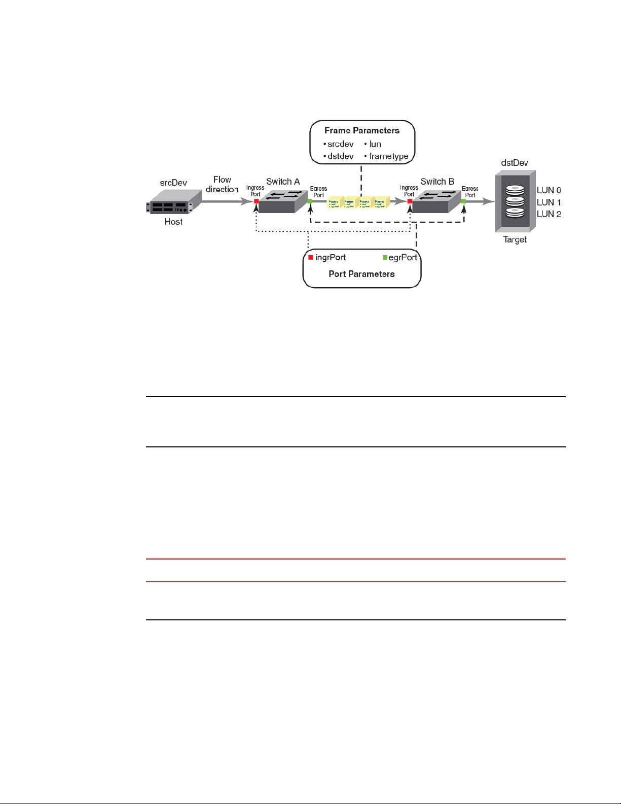
FIGURE 1 Frame and port parameters
Flow definitions
Flow definitions
To define a flow and configure Flow Vision to monitor that flow, you must provide a unique flow name
and specify the flow parameters. These parameters identify the sets of related frames that compose the
flow; these can either be explicitly defined or Flow Vision can learn them through observation.
NOTE
These flow definitions are stored on the switch on which the flow is created, and are not distributed
across the fabric. This means that each switch (logical or physical) knows only its own unique flows and
does not know what flows exist on other switches.
When creating or viewing a flow, you can specify any combination of the three features (monitor, mirror,
generator) in the flow command.
Flow definition parameters and rules
The rules listed in the following table identify the parameters that can be used to define a flow.
Flow definition rulesTABLE 3
Parameters Field names Rules
Port ingrport
egrport
• One field only must be specified
• Values must be explicit
Flow Vision Administrators Guide 17
53-1003168-01
Page 18

Duplicate flow definition support
Parameters Field names Rules
Flow definition rules (Continued)TABLE 3
Frame srcdev
dstdev
lun
frametype
NOTE
Refer to Table 5 on page 19 for more information
on frame types.
• At least one field must be specified.
• Values for srcdev and dstdev can be
explicit or "*" ("*" indicates learned
flows).
• Values for lun and frametype must be
explicit.
• On XISL monitors, the SFID and DFID
values are mandatory but srcdev &
dstdev are not.
Notes
• On 8 Gbps-capable Fibre Channel platforms, possible frame monitoring flow classifiers include:
egrport, ingrport, srcdev, dstdev, and lun.
• On Gen 5 Fibre Channel platforms and the Brocade FC8-32E and FC8-48E blades, possible frame
monitoring flow classifiers include: ingrport, egrport, dstdev, srcdev, and lun.
Duplicate flow definition support
Flow Vision allows duplicate flow definitions to be created as long as the flows are not active.
Duplicate flow definitions are detected during flow activation. If a flow is a duplicate of an active flow,
the duplicate will not be activated.
Any flow that is considered to be a duplicate will remain deactivated as long as there is an existing
matching flow definition active irrespective of the defined application. A warning message is displayed
when you try to create (which implicitly activates) or activate a flow if there is an existing matching flow
definition active. You must manually deactivate the active flow to activate the new flow definition.
A flow definition must be active to be considered a duplicate. For example, the following user-defined
flow definitions are considered to be duplicates, as the "*" value for dstdev in the second example
would include the 0xa20c81 value specified in the first.
flow --create flow1 -feature monitor -ingrport 9/46 -srcdev 0xb2c680 -
•
dstdev 0xa20c81
flow --create flow2 -feature monitor -ingrport 9/46 -srcdev 0xb2c680 -
•
dstdev *
However, these user-defined flow definitions will not be considered to be duplicates:
flow --create flow1 -feature monitor -ingrport 9/46 -srcdev 0xb2c680 -
•
dstdev 0xa20c81
flow --create flow2 -feature monitor -ingrport 9/46 -srcdev 0xb2c680 -
•
dstdev 0xa20c81 –noactivate
flow --create flow3 -feature generator -ingrport 9/46 -srcdev 0xb2c680 -
•
dstdev 0xa20c81 -noactivate
Predefined flows are considered when checking for duplicate flows. When a predefined flow is active
for any feature, all user-defined flows for that feature are considered to be duplicate flows, but userdefined flows for different features are not considered to be duplicate flows. Duplicate predefined flow
definitions can be active for different applications. Duplicate predefined flow definitions cannot be
active simultaneously for the same application.
18 Flow Vision Administrators Guide
53-1003168-01
Page 19

Supported port configurations for each application
Supported port configurations for each application
The following table lists the supported configurations for each Flow Vision feature that can be made
using only the basic flow identification parameters (ingrport and srcdev, egrport and dstdev).
Port configurations supported in Flow Vision TABLE 4
Switch Configuration Mode
Access Gateway Virtual Fabric
Not Supported Supported
Supported
(F_Ports only)
Supported
Feature
Flow
Generator
Flow
Mirror
Flow
Monitor
Platforms
16 Gbps-capable Fibre Channel
(Gen 5)
Supported (SIM ports only) Supported (Destination
Supported (F_Ports and F_Port
trunks)
Supported (E_Ports, EX_Ports,
F_Ports, SIM ports, and
XISL_Ports)
8 Gbps-capable Fibre
Channel
SIM ports only)
Not Supported Not Supported Supported
Supported (E_Ports,
EX_Ports, F_Ports, and
XISL_Ports)
Notes on supported configurations
• Neither ranges nor lists are supported for any parameter.
• If you are using at least one advanced parameter (lun, frametype, or bidir), then feature-specific rules
apply. Refer to the individual Flow Vision features for specific details.
• Support for Gen 5 F_Ports and F_Port trunks is provided on the following devices:
‐ Switches: Brocade 6505, 6510, 6520, DCX 8510-4 and DCX 8510-8
‐ Blades: CR16-4, CR16-8, FC8-32E, FC8-48E, FC16-32, FC16-48, and FC16-64
‐ Disabling a SIM port that is receiving traffic may produce class 3 discards for the simulated
traffic; however, this will have no effect on other traffic flows.
Flow frametype parameters
Frame monitoring can be done for a variety of frames using predefined frametype parameters.
The following table lists these parameters and the type of frames counted for each.
Supported frametype parametersTABLE 5
Frametype
parameter
abts Abort Sequence
baacc All frames accepted
barjt All frames rejected
scsi All SCSI frames (including both command and data frames)
scsiread Only SCSI read command frames
Flow Vision Administrators Guide 19
53-1003168-01
Frames counted
Page 20

Numbers of flows supported
Supported frametype parameters (Continued)TABLE 5
Frametype
parameter
scsiwrite Only SCSI write command frames
scsirw Both SCSI read and write command frames
scsi2reserve Only SCSI 2 reserve command frames
scsi3reserve Only SCSI 3 reserve command frames
scsi2release Only SCSI 2 release command frames
scsi3release Only SCSI 3 release command frames
scsi2reserverelease Only SCSI 2 reserve-release command frames
scsi3reserverelease Only SCSI 3 reserve-release command frames
scsitur Only SCSI test unit ready frames
scsistatus Only SCSI status frames
scsicmdsts Only SCSI command status frames
Frames counted
NOTE
This parameter is valid only for Flow Mirror. It implicitly assumes “-bidir” and looks for both
SCSI command and status frames.
scsigoodstatus Only SCSI status frames with status marked as good (all 0s [zeros] in the status byte)
scsicheckstatus Only SCSI status frames with check status (Check Condition, Busy, Reservation Conflict,
scsiinquiry Only SCSI inquiry frames
scsiresvconflict Only SCSI status frames with reservation conflict set
scsixferrdy Only SCSI FCP XFER_RDY (transfer ready) frames
Task Full Set)
Numbers of flows supported
On chassis-based platforms, Flow Vision supports a maximum of 512 user-defined flows plus an
additional 512 learned flows and predefined flows. On fixed-port platforms, Flow Vision supports a
maximum of 128 user-defined flows plus an additional 128 learned flows and predefined flows.
However, there is a combined limit for all features of 64 static flows and learning flows (whether active
or inactive) for any one port, and a maximum of 64 learned flows per feature per port. This means (as
an example) that two different learning flows on a given port can each have 64 learned flows.
Beyond these limits, there are limits for each individual feature, as described in the following table. In
addition, refer to the individual features for other feature-specific restrictions.
20 Flow Vision Administrators Guide
53-1003168-01
Page 21

Flow learning
NOTE
A verification is done for each flow when it is created or activated to ensure that there is no identical
flow active. Duplicate flows will not be created or activated when there is a identical flow already active.
To create a new flow that duplicates an active flow, you must use the -noactivate keyword as part of
the flow --create command. Refer to the “Creating an inactive flow” section of each feature for
instructions on creating an inactive flow for that feature.
Feature-specific flow count restrictions in Flow VisionTABLE 6
Feature Limit to number of flows
Flow Monitor Up to 64 active flows per port, including static flows, learning flows, and learned flows.
Flow Generator Up to 39 active flows per port for ingress ports and 64 active flows per port for egress
Flow Mirror One active flow per port.
ports.
Flow learning
Flow Vision can create a learned flow by using an asterisk (*) for the source device, the destination
device, or both devices. This allows you to discover what flows are active on a port without having to
explicitly identify all the devices.
The following items should be kept in mind when constructing learning flows:
• Learning is enabled on a port if the flow definition has an asterisk as the value for any of the flow
parameters. The learning flow is expanded to learned flows based on the parameters indicated by
the asterisk. Cumulative data is presented for parameters for which learning is not requested.
• When you enter an asterisk as part of the command to indicate a learned flow, you must enclose it in
double quotes, like this: ("*").
• Learning source device (srcdev) or destination device (dstdev) values are only supported on Gen 5
Fibre Channel ports.
• Each Flow Vision feature uses learning as follows:
‐ Flow Monitor can learn all the source device and destination device pairs passing through
the ingress or egress port defined in a flow. Learning is not supported for Flow Monitor flows
defined using the lun, frametype, or bidir parameters. Refer to Learning in Flow Monitor
flows on page 37 for additional information.
‐ Flow Generator can generate traffic to or from every source or destination device that
shares the zone with the ingress or egress port defined in a flow. Refer to Learning in Flow
Generator flows on page 65 for additional information.
‐ Flow Mirror can capture all the source device and destination device pairs passing through
the ingress or egress port defined in a flow. Learning is supported for Flow Mirror flows
defined using the lun, frametype, or bidir parameters. Refer to Learning in Flow Mirror flows
on page 83 for additional information.
Flow Vision Administrators Guide 21
53-1003168-01
Page 22

Viewing flows
Viewing flows
Flow Vision allows you to view the configuration parameters for each flow on a switch.
• To display all Flow Vision flows, enter flow --show.
• To display all flows for a specific feature, enter flow --show -feature feature_name.
• To display the definition for a specific flow, enter flow --show flow_name -feature feature_name.
When you enter flow --show with a flow name, only the flow definition for the specified flow is
displayed. If the feature is also specified, feature-specific data is displayed for the specified flow
name. For root and static flows, this command shows the Source ID-Destination ID pairs and the
cumulative frame count for the ingress or egress port specified in the flow definition.
The following example displays all the existing flows on the switch.
switch:admin> flow --show
------------------------------------------------------------------------------------------------------Flow Name | Feature |SrcDev | DstDev |IngrPt|EgrPt |BiDir|LUN |FrameType|SFID|DFID|MirPt |
------------------------------------------------------------------------------------------------------local |gen |- |019200 |13 |- |no |- |- |- |- |- |
flow2 |gen+,mon+ |010900 |01c100 |1/9 |- |no |- |- |- |- |- |
flow1 |gen+,mon+ |01c100 |- |8/1 |- |no |- |- |- |- |- |
sys_gen_all_simports|gen |* |* |* |* |no |- |- |- |- |- |
------------------------------------------------------------------------------------------------------ + Denotes feature is currently activated for the flow
The flow name with prefix sys_ denotes a predefined flow
Refer to the individual features to see feature-specific output.
Repeating flow output
You can configure the Flow Vision features to repeat their flow output. The purpose of repeating a flow
is so that you can view sample frames or output over time to look for differences. This allows you to
continuously monitor a changing situation.
To specify the number of times the flow output should be repeated, complete the following steps.
1. Connect to the switch and log in using an account with admin permissions.
2. Use the flow --show flow_name -feature feature_name -count num command. The num value can
range from 1 through 10. The default value is 1.
22 Flow Vision Administrators Guide
53-1003168-01
Page 23

Flow Vision
Repeating a Flow Monitor flow
The following example creates a Flow Monitor flow named “ag159_flow_2”, and
then repeats the output two times:
switch:admin> flow --create ag159_flow_2 -feature monitor -srcdev 10:05:00:11:0d:78:45:02 -dstdev
10:00:8c:7c:ff:43:c0:01 -ingrport 3/2 -bidir
switch:admin> flow --show ag159_flow_2 -feature monitor -count 2
=======================================================================================================
Name : ag159_flow_2 Features: mon(Activated) noConfig: Off
Definition: IngrPort(3/2),SrcDev(10:05:00:11:0d:78:45:02),DstDev(10:00:8c:7c:ff:43:c0:01),BiDir
Flow Monitor (Activated):
Monitor time: | Mon Jun 16 19:04:42 UTC 2014 |
---------------------------------------------------------
-----------------------------------------------------------------------------------------------------| Frame Count | Frames Per Sec. | Byte Count | Throughput(Bps) |FrmSize(B) |
| Tx / Rx / Total | Tx / Rx /Total | Tx /Rx /Total | Tx / Rx /Total | Tx / Rx |
-----------------------------------------------------------------------------------------------------|382.91M/394.17M/777.08M|46.93k/48.16k/95.10k|703.75G/701.23G/1.37T|88.34M/87.72M/176.07M|1976/1912 |
------------------------------------------------------------------------------------------------------
------------------------------------------------------------------------------------------------| I/O Count | I/O Per Sec.(IOPS) | I/O bytes Transferred | I/O bytes Per Sec. |
| Reads / Writes/ Total | Reads / Writes/ Total | Reads / Writes/ Total | Reads / Writes/ Total |
------------------------------------------------------------------------------------------------| 11.26M/ 11.26M/ 22.52M| 1.40k/ 1.39k/ 2.80k|687.43G/687.43G/ 1.34T| 87.85M/ 87.46M/175.31M|
------------------------------------------------------------------------------------------------=======================================================================================================
=======================================================================================================
Name : ag159_flow_2 Features: mon(Activated) noConfig: Off
Definition: IngrPort(3/2),SrcDev(10:05:00:11:0d:78:45:02),DstDev(10:00:8c:7c:ff:43:c0:01),BiDir
Flow Monitor (Activated):
Monitor time: | Mon Jun 16 19:04:48 UTC 2014 |
---------------------------------------------------------
------------------------------------------------------------------------------------------------------| Frame Count | Frames Per Sec. | Byte Count | Throughput(Bps) |FrmSize(B)
| Tx / Rx / Total | Tx / Rx /Total | Tx /Rx /Total | Tx / Rx /Total |Tx / Rx |
------------------------------------------------------------------------------------------------------|383.23M/394.50M/777.74M|53.69k/55.40k/109.09k|704.34G/701.82G/1.37T|101.04M/100.94M/201.98M|1976/1912|
-------------------------------------------------------------------------------------------------------
------------------------------------------------------------------------------------------------| I/O Count | I/O Per Sec.(IOPS) | I/O bytes Transferred | I/O bytes Per Sec. |
| Reads / Writes/ Total | Reads / Writes/ Total | Reads / Writes/ Total | Reads / Writes/ Total |
------------------------------------------------------------------------------------------------| 11.27M/ 11.27M/ 22.54M| 1.53k/ 1.54k/ 3.08k| 688G/688.00G/ 1.34T| 96.20M/ 96.69M/192.89M|
------------------------------------------------------------------------------------------------=======================================================================================================
Flow Vision Administrators Guide 23
53-1003168-01
Page 24

Flow Vision
Repeating a Flow Generator flow
The following example creates a Flow Generator flow named “simflow_1”, and
then repeats the output three times:
switch:admin> flow --create simflow_1 -feature generator -srcdev 07f000 -dstdev 371400 -ingrport 12/16
switch:admin> flow --show simflow_1 -feature generator -count 3
=======================================================================================================
Name : simflow_1 Features: gen(Activated),mon(Activated) noConfig: Off
Definition: IngrPort(12/16),SrcDev(0x07f000),DstDev(0x371400)
Flow Generator (Activated):
----------------------| SrcDev | DstDev |
----------------------| 0x07f000 | 0x371400 |
----------------------Number of frames generated from IngrPort : 2.57G
=======================================================================================================
=======================================================================================================
Name : simflow_1 Features: gen(Activated),mon(Activated) noConfig: Off
Definition: IngrPort(12/16),SrcDev(0x07f000),DstDev(0x371400)
Flow Generator (Activated):
----------------------| SrcDev | DstDev |
----------------------| 0x07f000 | 0x371400 |
----------------------Number of frames generated from IngrPort : 2.58G
=======================================================================================================
24 Flow Vision Administrators Guide
53-1003168-01
Page 25

Flow Vision
Repeating a Flow Mirror flow
The following example creates a bidirectional Flow Mirror flow named
“fmcount_cfm” that is mirrored to the CPU, and repeats the output three times:
switch:admin> flow --create fmcount_cfm -feature mirror -ingrport 10 -srcdev 010403 -dstdev 020504 bidir
switch:admin> flow --show fmcount_cfm -fea mir -count 3
=======================================================================================================
Name : fmcount_cfm Features: mir(Activated) noConfig: Off
Definition: IngrPort(14),SrcDev(0x010e00),DstDev(0x010f00),BiDir
Flow Mirror (Activated):
-------------------------------------------------------------------------------------| OXID | RXID | SOF | EOF | Frame_type | LUN(*) | Dir | Time-Stamp |
-------------------------------------------------------------------------------------| 0001 | ffff | SOFn3 | EOFn | Data | ---- | Rx | Jun 05 07:54:27:100 |
| 0044 | ffff | SOFn3 | EOFn | Data | ---- | Tx | Jun 05 07:54:27:100 |
(output truncated)
| 0001 | ffff | SOFn3 | EOFn | Data | ---- | Rx | Jun 05 07:54:31:109 |
| 0044 | ffff | SOFn3 | EOFn | Data | ---- | Tx | Jun 05 07:54:31:109 |
------------------------------------------------------------------------------------------- No of Mirrored Frames : 1280, No of RX Mirrored Frames : 640, No of TX Mirrored Frames : 640
-------------------------------------------------------------------------------------------=======================================================================================================
=======================================================================================================
Name : fmcount_cfm Features: mir(Activated) noConfig: Off
Definition: IngrPort(14),SrcDev(0x010e00),DstDev(0x010f00),BiDir
Flow Mirror (Activated):
-------------------------------------------------------------------------------------| OXID | RXID | SOF | EOF | Frame_type | LUN(*) | Dir | Time-Stamp |
-------------------------------------------------------------------------------------| 0001 | ffff | SOFn3 | EOFn | Data | ---- | Rx | Jun 05 07:54:34:100 |
| 0044 | ffff | SOFn3 | EOFn | Data | ---- | Tx | Jun 05 07:54:34:100 |
(output truncated)
| 0001 | ffff | SOFn3 | EOFn | Data | ---- | Rx | Jun 05 07:54:38:109 |
| 0044 | ffff | SOFn3 | EOFn | Data | ---- | Tx | Jun 05 07:54:38:109 |
------------------------------------------------------------------------------------------- No of Mirrored Frames : 1280, No of RX Mirrored Frames : 640, No of TX Mirrored Frames : 640
-------------------------------------------------------------------------------------------=======================================================================================================
=======================================================================================================
Name : fmcount_cfm Features: mir(Activated) noConfig: Off
Definition: IngrPort(14),SrcDev(0x010e00),DstDev(0x010f00),BiDir
Flow Mirror (Activated):
-------------------------------------------------------------------------------------| OXID | RXID | SOF | EOF | Frame_type | LUN(*) | Dir | Time-Stamp |
-------------------------------------------------------------------------------------| 0001 | ffff | SOFn3 | EOFn | Data | ---- | Rx | Jun 05 07:54:40:100 |
| 0044 | ffff | SOFn3 | EOFn | Data | ---- | Tx | Jun 05 07:54:40:100 |
(output truncated)
| 0001 | ffff | SOFn3 | EOFn | Data | ---- | Rx | Jun 05 07:54:44:109 |
| 0044 | ffff | SOFn3 | EOFn | Data | ---- | Tx | Jun 05 07:54:44:109 |
------------------------------------------------------------------------------------------- No of Mirrored Frames : 1280, No of RX Mirrored Frames : 640, No of TX Mirrored Frames : 640
-------------------------------------------------------------------------------------------=======================================================================================================
The following example creates a Flow Mirror flow named “fmcount_lfm” that is
mirrored to local port 16, and repeats the output five times:
switch:admin> flow --create fmcount_lfm -feature mirror -ingrport 14 -srcdev 010403 -dstdev 020504 mirrorport 16
switch:admin> flow --show fmcount_lfm -feature mirror -count 5
=======================================================================================================
Name : fmcount_lfm Features: mir(Activated) noConfig: Off
Definition: IngrPort(14),SrcDev(0x010e00),DstDev(0x010f00),MirPort(16)
Flow Mirror (Activated):
------------------------------------------------------------------------------------------- No of Mirrored Frames : 1032316, No of RX Mirrored Frames : 1032316, No of TX Mirrored Frames : 0
--------------------------------------------------------------------------------------------
=======================================================================================================
Flow Vision Administrators Guide 25
53-1003168-01
Page 26

Sorting flow output
=======================================================================================================
Name : fmcount_lfm Features: mir(Activated) noConfig: Off
Definition: IngrPort(14),SrcDev(0x010e00),DstDev(0x010f00),MirPort(16)
Flow Mirror (Activated):
------------------------------------------------------------------------------------------- No of Mirrored Frames : 1267119, No of RX Mirrored Frames : 1267119, No of TX Mirrored Frames : 0
-------------------------------------------------------------------------------------------=======================================================================================================
=======================================================================================================
Name : fmcount_lfm Features: mir(Activated) noConfig: Off
Definition: IngrPort(14),SrcDev(0x010e00),DstDev(0x010f00),MirPort(16)
Flow Mirror (Activated):
------------------------------------------------------------------------------------------- No of Mirrored Frames : 1501921, No of RX Mirrored Frames : 1501921, No of TX Mirrored Frames : 0
-------------------------------------------------------------------------------------------=======================================================================================================
=======================================================================================================
Name : fmcount_lfm Features: mir(Activated) noConfig: Off
Definition: IngrPort(14),SrcDev(0x010e00),DstDev(0x010f00),MirPort(16)
Flow Mirror (Activated):
------------------------------------------------------------------------------------------- No of Mirrored Frames : 1736723, No of RX Mirrored Frames : 1736723, No of TX Mirrored Frames : 0
-------------------------------------------------------------------------------------------=======================================================================================================
=======================================================================================================
Name : fmcount_lfm Features: mir(Activated) noConfig: Off
Definition: IngrPort(14),SrcDev(0x010e00),DstDev(0x010f00),MirPort(16)
Flow Mirror (Activated):
------------------------------------------------------------------------------------------- No of Mirrored Frames : 1971525, No of RX Mirrored Frames : 1971525, No of TX Mirrored Frames : 0
-------------------------------------------------------------------------------------------=======================================================================================================
Sorting flow output
In Flow Vision, frames can be sorted whether or not sub-flows are present. Sorting the output allows
you to highlight a selected aspect of the flow data.
To sort the flow output, complete the following steps.
1. Connect to the switch and log in using an account with admin permissions.
2. Use the flow --show flow_name -feature feature_name -sortby columncolumn_num command.
The columncolumn_num value is the number of the output column on which the data is to be
sorted. There is no space between “column” and the column number.
NOTE
The -sortby parameter can only be applied when there is only one feature (monitor, mirror, or
generator) specified in the flow --show flow_name command.
26 Flow Vision Administrators Guide
53-1003168-01
Page 27

Flow Vision
Sorting a Flow Monitor flow
Flow Monitor flows only would nee d sorting if they are a learned flow, as sorting
with the dstdev and srcdev explicitly defined would not make sense because
there would be only one line of data in the output. The table headings have been
edited so that they will display more clearly in this document.
The following example creates the Flow Monitor flow “neutrons”, and then shows
the output sorted by column 4, the Destination ID.
switch:admin> flow --create neutrons -feature monitor -egrport 1212 -dstdev "*" -srcdev "*"
switch:admin> flow --show neutrons -feature monitor -sortby column4
Monitor time: | Mon Jun 16 21:46:52 UTC 2014 |
--------------------------------------------------------=======================================================================================================
Name : neutrons Features: mon(Activated) noConfig: Off
Definition: EgrPort(1212),SrcDev(*),DstDev(*),SFID(*),DFID(*)
Flow Monitor (Activated):
------------------------------------------------------------------------------------------------------|SFID(*)|DFID(*)|SID(*)|DID(*)|Tx Frm Cnt|Tx Frm/Sec.|Tx Bytes Cnt|Tx Throughput(Bps)|Avg Tx Frm Sz(B)|
------------------------------------------------------------------------------------------------------| 25| 25|0ffe80|01cd40| 50.59k | 8.38k | 1.28G | 16.97M | 2124 |
| 25| 25|0fffc0|01cec0| 752.38k | 9.65k | 1.48G | 19.55M | 2124 |
| 25| 25|0fff40|01e800| 634.85k | 8.17k | 1.25G | 16.55M | 2124 |
| 25| 25|0ffe00|01efc0| 742.98k | 9.53k | 1.46G | 19.30M | 2124 |
| 45| 45|3c8340|5ac9c0| 303.27k | 3.92k | 614.30M | 7.94M | 2120 |
| 45| 45|3cf140|5ac9c0| 174.55k | 2.22k | 353.58M | 4.49M | 2124 |
| 45| 45|3cfc00|5ac9c0| 562.38k | 7.27k | 1.11G | 14.73M | 2120 |
| 45| 45|3cfd00|5aca00| 981.76k | 12.61k | 1.94G | 25.54M | 2120 |
| 45| 45|3cb000|5aca00| 1.02M | 12.99k | 2.03G | 26.31M | 2120 |
| 45| 45|3c8340|5aca00| 301.74k | 3.90k | 611.20M | 7.90M | 2124 |
| 45| 45|3cdcc0|5aca00| 653.07k | 8.48k | 1.29G | 17.17M | 2120 |
| 45| 45|3cfd00|5aca40| 960.02k | 12.33k | 1.89G | 24.97M | 2120 |
| 45| 45|3cbe00|5aca40| 418.35k | 5.33k | 847.41M | 10.81M | 2120 |
| 45| 45|3c8340|5aca80| 262.76k | 3.41k | 532.25M | 6.91M | 2120 |
| 45| 45|3cdcc0|5aca80| 630.51k | 8.16k | 1.24G | 16.54M | 2124 |
| 45| 45|3cfd00|5aca80| 946.89k | 12.17k | 1.87G | 24.65M | 2120 |
| 45| 45|3cf140|5aca80| 175.48k | 2.22k | 355.45M | 4.51M | 2124 |
| 45| 45|3cbd00|5aca80| 52.19k | 661 | 105.72M | 1.33M | 2124 |
| 45| 45|3cbd00|5acac0| 64.22k | 807 | 130.09M | 1.63M | 2124 |
| 45| 45|3c82c0|5acac0| 209.24k | 2.75k | 423.85M | 5.58M | 2124 |
| 45| 45|3cfc00|5acac0| 570.87k | 7.36k | 1.12G | 14.92M | 2124 |
| 45| 45|3c8340|5acac0| 404.76k | 5.23k | 819.88M | 10.61M | 2124 |
| 45| 45|3cf140|5acac0| 168.94k | 2.14k | 342.21M | 4.34M | 2124 |
| 45| 45|3cf040|5acac0| 108.99k | 1.40k | 220.78M | 2.84M | 2124 |
| 45| 45|3cdd40|5acac0| 412.87k | 5.34k | 836.30M | 10.81M | 2120 |
| 45| 45|3cbe00|5acac0| 396.50k | 5.05k | 803.16M | 10.23M | 2124 |
| 45| 45|3c8300|5ace00| 970.02k | 12.43k | 1.91G | 25.19M | 2124 |
| 45| 45|3cbcc0|5ace00| 42.39k | 538 | 85.87M | 1.09M | 2124 |
| 45| 45|3cdd00|5ace00| 952.45k | 12.37k | 1.88G | 25.07M | 2120 |
| 45| 45|3cbf40|5ace00| 448.57k | 5.67k | 908.62M | 11.49M | 2124 |
Sorting a Flow Generator flow
The following example creates a Flow Generator flow, and then shows the output
sorted by column 2:
switch:admin> flow --create fSort -feature generator -egrport 4/8 -dstdev 022a00 srcdev 01d8c0
switch:admin> flow --show fSort -feature generator -sortby column2
Flow Vision Administrators Guide 27
53-1003168-01
Page 28

Flow deletion
Sorting a Flow Mirror flow
The following example creates a Flow Mirror flow, and then shows the output
sorted by column 3, the OXID.
switch:admin> flow --create sortMirror -feature mirror -egrport 15 -srcdev "*" -bidir
switch:admin> flow --show sortMirror -feature mirror -sortby column3
=======================================================================================================
Name : sortMirror Features: mir(Activated) noConfig: Off
Definition: EgrPort(15),SrcDev(*),BiDir
Flow Mirror (Activated):
------------------------------------------------------------------------------------------------------| SID(*) | DID(*) | OXID | RXID | SOF | EOF | Frame_type | LUN(*) | Dir | Time-Stamp |
------------------------------------------------------------------------------------------------------| 010e00 | 010f00 | 0001 | ffff | SOFn3 | EOFn | Data | ---- | Tx | Jun 05 10:16:50:100 |
| 010e00 | 010f00 | 0001 | ffff | SOFn3 | EOFn | Data | ---- | Tx | Jun 05 10:16:50:101 |
| 010e00 | 010f00 | 0001 | ffff | SOFn3 | EOFn | Data | ---- | Tx | Jun 05 10:16:50:102 |
| 010e00 | 010f00 | 0001 | ffff | SOFn3 | EOFn | Data | ---- | Tx | Jun 05 10:16:50:103 |
| 010e00 | 010f00 | 0001 | ffff | SOFn3 | EOFn | Data | ---- | Tx | Jun 05 10:16:50:104 |
| 010e00 | 010f00 | 0001 | ffff | SOFn3 | EOFn | Data | ---- | Tx | Jun 05 10:16:50:105 |
| 010e00 | 010f00 | 0001 | ffff | SOFn3 | EOFn | Data | ---- | Tx | Jun 05 10:16:50:106 |
| 010e00 | 010f00 | 0001 | ffff | SOFn3 | EOFn | Data | ---- | Tx | Jun 05 10:16:50:107 |
| 010e00 | 010f00 | 0001 | ffff | SOFn3 | EOFn | Data | ---- | Tx | Jun 05 10:16:50:108 |
| 010e00 | 010f00 | 0001 | ffff | SOFn3 | EOFn | Data | ---- | Tx | Jun 05 10:16:50:109 |
| 010e00 | 010f00 | 0001 | ffff | SOFn3 | EOFn | Data | ---- | Tx | Jun 05 10:16:50:110 |
| 010e00 | 010f00 | 0001 | ffff | SOFn3 | EOFn | Data | ---- | Tx | Jun 05 10:16:51:104 |
| 010f00 | 010e00 | 0044 | ffff | SOFn3 | EOFn | Data | ---- | Rx | Jun 05 10:16:51:111 |
| 010f00 | 010e00 | 0044 | ffff | SOFn3 | EOFn | Data | ---- | Rx | Jun 05 10:16:52:104 |
| 010f00 | 010e00 | 0044 | ffff | SOFn3 | EOFn | Data | ---- | Rx | Jun 05 10:16:52:104 |
| 010f00 | 010e00 | 0044 | ffff | SOFn3 | EOFn | Data | ---- | Rx | Jun 05 10:16:53:106 |
| 010f00 | 010e00 | 0044 | ffff | SOFn3 | EOFn | Data | ---- | Rx | Jun 05 10:16:54:109 |
(output truncated)
------------------------------------------------------------------------------------------- No of Mirrored Frames : 1280, No of RX Mirrored Frames : 640, No of TX Mirrored Frames : 640
-------------------------------------------------------------------------------------------=======================================================================================================
Flow deletion
Flow Vision allows you to delete either individual flows or all flows at one time.
When you delete a flow, the following actions occur:
• The specified flow is automatically deactivated before it is deleted.
• All instances of the specified flow are removed.
• Any sub-flows associated with the specified flow are removed.
• If the specified flow is a Flow Monitor or Flow Mirror flow, all flow statistics for it are automatically
cleared. If the specified flow is a Flow Generator flow, the statistics are retained.
• You are not asked to confirm the deletion, unless you use all as the flow name and do not use the force keyword. For example: flow --delete all.
For more information on the flow --delete command, refer to the Fabric OS Command Reference.
Deleting flows
Flow Vision allows you to delete either a single flow or all flows.
Deleting a single flow
To delete any Flow Vision flow, complete the following steps.
28 Flow Vision Administrators Guide
53-1003168-01
Page 29

Deleting all flows at one time
1. Connect to the switch and log in using an account with admin permissions.
2. Enter flow --delete flow_name.
The named flow is immediately deleted and cannot be recovered.
The following example deletes a Flow Monitor flow named “Flow1”.
switch:admin> flow --delete Flow1
Deleting all flows at one time
To delete all Flow Vision flows at one time, complete the following steps.
1. Connect to the switch and log in using an account with admin permissions.
2. Enter flow --delete all.
You are then prompted to confirm this action.
3. Enter y.
All user-defined Flow Vision flows will be deleted and cannot be recovered. Predefined flows will not
be deleted, but they will be deactivated.
NOTE
You can compel the deletion of flows by adding the -force keyword to the command. Using this
keyword causes Flow Vision to not issue a confirmation prompt.
The following example deletes all flows without prompting you for confirmation.
switch:admin> flow --delete all -force
Resetting flow statistics
Flow Vision allows you to clear (reset) the flow statistics record for each feature individually or as a
group.
NOTE
Clearing the Flow Mirror statistics for a flow also clears the mirrored frames.
Clearing the statistics for all flow features
To clear all the statistics for a flow, complete the following steps.
1. Connect to the switch and log in using an account with admin permissions.
2. Enter flow --reset flow_name -feature all.
You will not be asked to confirm this action.
The following example clears only the Flow Monitor statistics for the flow named
“Flow4”.
switch:admin> flow --reset Flow4 -feature monitor
Flow Vision Administrators Guide 29
53-1003168-01
Page 30

Clearing the statistics for a specific flow feature
Clearing the statistics for a specific flow feature
To clear the statistics for specified features of a flow, complete the following steps.
1. Connect to the switch and log in using an account with admin permissions.
2. Enter flow --reset flow_name -feature feature_list. Replace feature_list with either an individual
feature or a comma-separated list of features (for example, “generator,monitor” or “mir,mon”).
You will not be asked to confirm this action.
The following example clears only the Flow Monitor statistics for the flow named
“Flow4”.
switch:admin> flow --reset Flow4 -feature monitor
Flow Vision licensing
To run Flow Vision, you need either the Fabric Vision (FV) license, or both the Fabric Watch (FW) and
the Advanced Performance Monitor (APM) licenses. If you have both of these licenses, you do not
need a separate Flow Vision license.
Refer to the Fabric OS Software Licensing Guide for more specific information about licensing and
how to obtain the needed license keys.
Flow Vision configuration setup
When a switch goes offline or comes online, Flow Vision reads the configuration files and then deletes
flows, creates flows, and activates flows. After a switch goes offline, any flows that were active at the
time it went offline will be reactivated when it comes back online and new traffic will be generated as
soon as the source and destination devices defined in the flow are online. This includes predefined
flows.
Use the following commands to upload, download, and delete configurations:
• To download a Flow Vision configuration to the switch, use the configDownload command.
• To save the Flow Vision configuration to the host FTP site, use the configUpload command.
• To delete all flows and simulation ports (SIM ports) from a switch, use the configDefault command.
NOTE
Statistical data for flows is not saved in the configuration database.
System event handling
Flow Vision handles the following system events:
30 Flow Vision Administrators Guide
53-1003168-01
Page 31

Firmware upgrade and downgrade considerations
• When an E_Port or F_Port comes online (PORT_ONLINE), if the resources are available, any flows
specifying that port will be installed in the ASIC and made active. If the resources are not available,
the flow will stay deactivated.
• When an E_Port is changed (EPORT_CHANGE), if the resources are available, any flows specifying
that port will be installed in the ASIC and made active. If the resources are not available (for
example, if there is already a flow using that port), the flow will stay deactivated.
• When an F_Port is changed (FPORT_CHANGE), if the resources are available, any flows specifying
that port will be installed in the ASIC and made active. If the resources are not available (for
example, if there is already a flow using that port), the flow will stay deactivated.
An F_Port trunk has same trunk index for both the master and slave ports (as displayed in the output
for switchshow, below). In order to create the same flow definition on the master and slave ports
when portIdMode is set to “index”, the domain/Index can be obtained by using the porttrunkarea –
show all command (as shown below). If you create a flow using the trunk index, then depending
upon whether the trunk index maps to the master or the slave port the flow may or may not be
installed. If the slave port becomes the master, it will be installed.
switch:admin> switchshow
…
Index Port Address Media Speed State Proto
==================================================
…
4 4 010400 id N8 Online FC F-Port (Trunk master)
4 5 010400 id N8 Online FC F-Port (Trunk port, master is Port 4)
…
switch:admin> porttrunkarea --show all
Port Type State Master TI DI
------------------------------------ 0 -- -- -- 0
1 -- -- -- 1
2 -- -- -- 2
3 -- -- -- 3
4 F-port Master 4 4 4
5 F-port Slave 4 4 5
• If a PID is changed for a WWN flow and the new PID does not match the PID in the flow definition,
the active flow will be uninstalled and then reinstalled with the updated PID in the flow definition.
Firmware upgrade and downgrade considerations
There are no restrictions on upgrading the firmware of a switch that has Flow Vision installed. However,
downgrading the firmware on a switch with Flow Vision installed will fail if any Flow Vision-related
configurations are present on the switch being downgraded. Both user-defined and system-defined
flows support the configuration upload and download procedures.
Flow Vision functionality will not be affected if a switch running Fabric OS 7.3.0 is connected to a switch
running Fabric OS 7.2.x. Connecting to a switch running any version of Fabric OS earlier than 7.2.0 will
disable Flow Vision.
Upgrade considerations
The following items should be taken into consideration when upgrading to Fabric OS 7.3.0:
• When moving a configuration from a switch running Fabric OS 7.2.x to one running 7.3.0, predefined
flows will be included automatically when the older configuration is downloaded to a switch running
Fabric OS 7.3.0, but they will remain deactivated after download.
• If the in-flight encryption and compression functionality is enabled, then any Flow Mirror flow active
before the upgrade will be deactivated after the upgrade and a RASlog entry displayed on the
console.
Flow Vision Administrators Guide 31
53-1003168-01
Page 32

High Availability and Flow Vision
Downgrade considerations
The following items should be taken into consideration when downgrading to a version of Fabric OS
earlier than 7.3.0:
• All Flow Vision-related flows or simulation ports must be deleted prior to performing a downgrade to
any version of Fabric OS prior to version 7.2.0; if they are not, the downgrade will be blocked and a
warning message displayed.
• Flow counts that exceed the supported scalability limits will not be replayed when downgraded or
failed over to a version of Fabric OS earlier than 7.3.0.
• Predefined flows will not be replayed, and flow definitions for newly introduced features will not be
replayed from the flow configuration.
• Downgrading from Fabric OS 7.3.0 is not allowed if a Flow Mirror flow is active for local flow
mirroring (LFM). You must first deactivate any active flow that is using a local mirror port.
• Flows that were created with the following keyword combinations are automatically deactivated.
‐ -bidir and -frametype
‐ -ingrport and -frametype
• Flows created using learning on E_Ports and EX_Ports will not be replayed after the downgrade.
• Flows created using monitor support on XISL ports will not be replayed after the downgrade.
• Flows will be deleted from memory configuration when firmware is downgraded.
High Availability and Flow Vision
High Availability (HA) preserves only the Flow Vision configuration settings through an HA failover, HA
reboot, or a power cycle and reboot. It does not save feature-related data (for example, statistics).
User-defined or system-defined (predefined) flows will not be restored if failed over to an earlier
version of Fabric OS.
If a standby command processor (CP) with a downgrade revision code comes online and any flows
(active or non-active) are configured, the HA will be out of sync. If a standby CP with a downgrade
revision code comes online and no flows (active or non-active) are configured, HA will be in sync but
flow creation will fail.
Refer to the following sections for information on how each feature is treated under HA:
• Flow Monitor and High Availability on page 57
• Flow Generator and High Availability on page 73
• Flow Mirror and High Availability on page 90
Flow Vision integration with MAPS
Statistics generated using Flow Vision can be monitored with the Monitoring and Alerting Policy Suite
(MAPS) threshold service.
Refer to the individual features for information on how that feature interacts with MAPS, and the
Monitoring and Alerting Policy Suite Administrator's Guide for more details on MAPS in general.
32 Flow Vision Administrators Guide
53-1003168-01
Page 33

Flow Monitor
● Overview of Flow Monitor ...............................................................................................33
● Creating Flow Monitor flows............................................................................................34
● Activating Flow Monitor flows..........................................................................................36
● Deactivating Flow Monitor flows......................................................................................36
● Viewing Flow Monitor flows.............................................................................................37
● Learning in Flow Monitor flows........................................................................................37
● Configuring Flow Monitor for a trunk group.....................................................................39
● Monitoring Fibre Channel routed fabrics......................................................................... 40
● XISL and Backbone E_Port monitoring...........................................................................50
● Flow Monitor examples .................................................................................................. 52
● Flow Monitor and High Availability.................................................................................. 57
● Flow monitors and MAPS................................................................................................57
● Flow monitors on Access Gateways............................................................................... 57
● Flow Monitor limitations...................................................................................................57
Overview of Flow Monitor
Flow Monitor enables you to monitor all the traffic passing through E_Ports, EX_Ports, F_Ports, and
XISL_Ports using any hardware-supported flow parameters. It also lets you define your own monitoring
flows using combinations of ingress and egress ports, source and destination devices, logical unit
numbers (LUNs), and frame types to create a flow definition for a specific use case.
Flow Monitor provides support for monitoring the following flows and traffic:
• Learning and static flows for traffic passing through E_Ports and F_Ports
• Learning and static flows monitoring edge-to-edge traffic, edge-to-backbone traffic, and backbone-toedge traffic passing through EX_Ports
• Learning and static flows monitoring traffic inside logical fabrics and inter-fabric (routed) traffic
passing through XISL_Ports
• Learning and static flows monitoring inter-fabric traffic and backbone traffic passing through
backbone E_Ports
In Fabric OS 7.1.x and earlier, the Advanced Performance Monitor (APM) provided the following
monitors: End-to-End, Frame-based, ISL, and Top Talker. In Fabric OS 7.3.0, Flow Monitor provides
you with the following abilities in addition to those provided by the APM monitors:
• Monitoring of application flows (for example, a flow within a fabric from a Host to a Target/LUN) at a
given port.
• Comprehensive visibility into application flows in a fabric, including the ability to learn (discover) flows
automatically.
• When N_Port ID Virtualization (NPIV) is used on the host, you can monitor VM (Virtual Machine)-toLUN level performance.
• Capturing statistics for specified flows, which provides insights into application performance. These
statistics include transmitted and received frame counts, transmitted and received frame throughput
rates, SCSI Read and SCSI Write frame counts, the number of SCSI Reads and Writes per second
(IOPS), as well as others.
Flow Vision Administrators Guide
53-1003168-01
33
Page 34

Replicating APM monitors using Flow Monitor
A sample use case would be to monitor throughput statistics for inbound traffic between a source
device and a destination device. Monitoring LUN level statistics on page 52 provides an example
of the command and the results for this use case.
• Monitoring of various frame types at a switch port to provide deeper insights into storage I/O access
patterns at a LUN, reservation conflicts, and I/O errors. Examples of the frame types that can be
monitored include SCSI Aborts, SCSI Read, SCSI Write, SCSI Reserve, all rejected frames, and
many others. Refer to Flow frametype parameters on page 19 for a list and description of the frame
types that can be monitored.
• The SCSI Read/Write Frame Count and SCSI Read/Write Data statistics are supported only for
F_Ports for any flow configuration where either srcdev or dstdev exists on the switch, and the flow is
defined using a combination of srcdev, dstdev, ingrport, or egrport (with or without bidir), or a
combination of srcdev, dstdev, lun, ingrport, or egrport.
• Integration with the Monitoring and Alerting Policy Suite (MAPS) service to enable threshold-based
monitoring and alerting based on flows. Refer to the Monitoring and Alerting Policy Suite
Administrator's Guide for more information on integration with MAPS.
Replicating APM monitors using Flow Monitor
It is possible to replicate standard Advanced Performance Monitor (APM) functionality using Flow
Monitor.
For information on replicating standard APM functionality using Flow Monitor, refer to the following
links:
• Creating an end-to-end monitor equivalent on page 55
• Creating a frame monitor equivalent on page 55
• Creating an ingress or egress Top Talker monitor equivalent on page 56
• Creating an end-to-end monitor equivalent on page 55
Creating Flow Monitor flows
To create a Flow Monitor flow, enter the flow --create flowname -feature monitor parameters
command using the parameters listed in the following table. The figure Frame and port parameters on
page 17 illustrates how the frame and port parameters apply to a flow.
Flow Monitor flow parameter combinations TABLE 7
Parameters Field names Description
Port ingrport
egrport
Frame srcdev
dstdev
lun
frametype
• One field only must be specified
• Values must be explicit
• Can be an F_Port, E_Port, or EX_Port on a local switch
• At least one field must be specified
• Values for srcdev and dstdev can be explicit or "*" ("*" indicates
learned flows)
• Values for lun and frametype must be explicit
Optional keyword parameters
34 Flow Vision Administrators Guide
53-1003168-01
Page 35

Flow Monitor flow parameter combinations (Continued)TABLE 7
Parameters Field names Description
Parameter usage exceptions
-bidir Adding this keyword makes the application monitor traffic in both
-noactivate Adding this keyword creates the flow without activating it.
-noconfig Adding this keyword creates the flow without saving the flow to the
directions.
configuration.
Parameter usage exceptions
The following restrictions apply to parameter usage in Flow Monitor flow definitions:
• The -lun and -bidir parameters cannot be used together in a flow definition.
• Flow Monitor does not support learning flows using the -frametype, -lun, or -bidir parameters.
The following example creates a Flow Monitor flow named “Flow1” that monitors all traffic flowing from
device 010403 to device 020504 ingressing through port 10 on the switch on which this command was
run.
switch:admin> flow --create Flow1 -feature monitor -ingrport 10 -srcdev 010403 dstdev 020504
When you create a flow, it is automatically activated unless you use the -noactivate keyword as part of
the flow --create command. Refer to Creating an inactive flow in Flow Monitor on page 35 for an
example of this option.
ATTENTION
Flow creation is not allowed if Advanced Performance Monitor (APM) or Port Mirroring is enabled.
Similarly, APM and Port Mirroring-related operations will not be allowed if any flow (active or defined) is
present on the switch.
Creating an inactive flow in Flow Monitor
The reason to create an inactive flow is to have it ready for future use. To create an inactive Flow
Monitor flow, enter flow --create flowname -feature feature_list flow_parameters -noactivate.
The following example creates an inactive Flow Monitor flow named “sflow128” from device 020a00 to
device 01c000 ingressing through port 10.
switch:admin> flow --create sflow128 -feature mirror -ingrport 10 -srcdev 0x020a00 dstdev 0x01c000 -noactivate
For information on activating an inactive Flow Monitor flow, refer to Activating Flow Monitor flows on
page 36.
Flow Vision Administrators Guide 35
53-1003168-01
Page 36

Activating Flow Monitor flows
Activating Flow Monitor flows
To activate an inactive Flow Monitor flow, enter flow --activate flowname -feature monitor. Activating
a flow automatically clears all the flow statistics for that flow.
The following example activates the Flow Monitor flow named “Flow1”:
switch:admin> flow --activate Flow1 -feature monitor
Automatic activation of a Flow Monitor flow
Flow Monitor automatically activates monitoring flows under the following conditions:
• On flow creation, unless the flow is created using the -noactivate keyword.
• On slot power-on, if any of the ports or devices defined in the flow are on the slots being powered
on. This assumes that the flow was active when the slots were powered off.
• On a High Availability (HA) failover, HA reboot, or a power cycle, if the flow was active when the
event occurred.
Deactivating Flow Monitor flows
You can deactivate Flow Monitor flows without deleting them. This allows you to create and store a
“library” of flows that you can activate when needed without having to recreate them every time they
are needed.
To deactivate a Flow Monitor flow, enter flow --deactivate flow_name -feature monitor.
NOTE
You can deactivate a single feature even though the flow is defined for multiple features. For example,
if a flow had been defined using “-feature monitor,generator”, you can deactivate only the monitoring
feature, while leaving the generator feature active.
The following example deactivates the Flow Monitor flow named “Flow1”.
switch:admin> flow --deactivate Flow1 -feature monitor
Automatic deactivation of a Flow Monitor flow
Flow Vision automatically deactivates Flow Monitor flows and stops monitoring if any of these
conditions occur:
• Slot is powered off for the ingress or egress ports defined in the flow.
• Slot is powered off for the source or destination devices defined in the flow.
• The ingress or egress port type changes to anything other than an E_Port, EX_Port, XISL_Port,
F_Port, or SIM port for a learned flow ("*"). The flow will not automatically reactivate if the port type
is changed back. You must manually reactivate such a flow.
• The ingress or egress port type changes to anything other than an E_Port, EX_Port, XISL_Port,
F_Port, or SIM port for a flow that has the lun or frametype value specified. The flow will not
automatically reactivate if the port type is changed back. You must manually reactivate such a flow.
36 Flow Vision Administrators Guide
53-1003168-01
Page 37

Viewing Flow Monitor flows
To display Flow Monitor flows, enter flow --show flowname -feature monitor.
The displayed information includes:
• Frame Statistics: Frame count and rate for the flow-defined frame type
• Throughput Statistics: Word count and throughput (bytes per second)
• I/O Statistics: I/O count, I/O per second, and I/O data transferred on a read/write basis
• Learn Statistics: All learned ("*") flows on a given port and the throughput and frame statistics for
each learned flow on 16 GBps-capable Fibre Channel platforms
You can also repeat and sort the output of a Flow Monitor flow. For information on these tasks, refer to
Repeating flow output on page 22 and Sorting flow output on page 26.
For illustrations of flow --show command output, refer to Flow Monitor examples on page 52.
Learning in Flow Monitor flows
Viewing Flow Monitor flows
You can apply learning in Flow Monitor flows in order to discover flow traffic. To apply learning to a Flow
Monitor flow, you enter an asterisk inside quotation marks ("*") as the parameter value for the
parameter to be learned.
The following list outlines the support for learning on various port types:
• F_Ports. Learning and static monitoring is supported.
• E_Ports. Learning and static monitoring is supported.
• EX_Ports. Learning and static monitoring is supported.
• XISL_Ports. Fabric wide learning and static monitoring is supported.
• Backbone E_Ports. Learning and static monitoring is supported.
• Trunked ports. Learning is supported, although statistics will be gathered only on the flow associated
with the master port. These statistics are the cumulative total of all the ports on the trunk.
Notes on learning in Flow Monitor flows
The following items apply to learning in Flow Monitor flows:
• Only Gen 5 (16 Gbps-capable) Fibre Channel platforms and 8 Gbps Enhanced blades have the
capability to learn flows on a specified port.
• Only one active flow per ASIC can be a learning flow.
• Using two flows to monitor traffic ingressing and egressing on the same ASIC is only supported if
both flows are static. If one flow is a learning flow, only the static flow will count frames.
• You can use either a WWN or a PID for the srcdev and dstdev values when creating learning flows
for Flow Monitor.
Creating Flow Monitor learning flows
Using learning flows in Flow Monitor allows you to discover flow traffic without having to identify specific
devices or ports.
Refer to Monitoring flows using the learning functionality on page 53 to view how to display the data
captured using a learning flow.
Flow Vision Administrators Guide 37
53-1003168-01
Page 38

Learning Flow creation on offline or slave ports
To create a leaning flow in Flow Monitor, complete the following steps.
1. Connect to the switch and log in using an account with admin permissions.
2. Enter flow --create flow_name -feature monitor port_values , using an asterisk in quotes ("*") for
those port and device values you want to be learned.
The following example creates a Flow Monitor learning flow named “ingressTT”
ingressing through port 30 (an E_Port).
switch:admin> flow --create ingressTT -feature monitor -ingrport 30 -srcdev "*" dstdev "*"
The following example creates a Flow Monitor learning flow named
“ex_lrn_ingr” which captures traffic ingressing through port 219 headed for
device 20:13:00:05:33:88:a3:90.
switch:admin> flow --create ex_lrn_ingr -feature monitor -ingrport 219 -srcdev "*" dstdev 20:13:00:05:33:88:a3:90
Learning Flow creation on offline or slave ports
Flows can be created that specify either an inactive or slave port in their definitions, but activation is
controlled not only by the port status, but by available resources and flow count limits.
• When a flow is created on an offline port, the flow is considered inactive until the port comes online.
However, the flow would only be installed in the ASIC and made active if the resources are
available. If the resources are not available the flow would remain deactivated.
• When a flow is created on a slave port, the flow is considered inactive until the port becomes the
master port. However, the flow would only be installed in the ASIC and made active if the resources
are available. If the resources are not available, the flow would remain deactivated.
Flow Monitor learning on E_Ports and EX_Ports
Flow Monitor supports learning and monitoring all the traffic passing through both E_Ports and
EX_Ports. The captured statistics are similar to the existing learning support provided for F_Ports.
As it is for F_Ports, learning is supported on trunked E_Ports and EX_Ports, and statistics are
gathered only on the flow associated with the master port. These statistics are the cumulative total
from all of the trunked ports. For this reason, you should create and use the same flow definition for
each of the ports in the trunk. You can use either a WWN or a PID value for the srcdev and dstdev
identifiers when creating learning flows.
While the source fabric ID to destination fabric ID option is allowed on any E_Port, it is needed only for
Backbone E_Ports and the XISL_Ports. If the source fabric ID to destination fabric ID combination is
configured on an edge E_Port learning flow, it will display the same source fabric ID to destination
fabric ID combination for all learned flows.
38 Flow Vision Administrators Guide
53-1003168-01
Page 39

Configuring Flow Monitor for a trunk group
FIGURE 2 Learning support in a Fibre Channel Routing fabric
The fixed parameters of a learning flow on an E_Port or an EX_Port should use the following
combinations when defining flows using specific ingress or egress ports:
• For flows using an ingress port (ingrport), the real source ID of the source device and the proxy ID of
the destination device.
• For flows using an egress port (egrport), the proxy ID of the source device and the real destination ID
of the destination device.
The flow --show output for an E_Port or an EX_Port will use the flow definition; in this output the proxy
ID of the destination device will be reported for flows defined using the ingress port, and the proxy ID of
the source device will be reported for flows defined using the egress port.
Monitoring flows using the learning functionality on page 53 provides examples of both the flow
command and the flow output.
Configuring Flow Monitor for a trunk group
Flow Monitor supports monitoring trunk ports subject to the following conditions:
• You must create the same flow on all trunk member ports.
• If you create a flow on a slave port without using the -noactivate keyword with the flow command,
this flow is then automatically activated when the slave port becomes the master port.
• After a switch initialization or a recovery (cold or warm), existing flows are re-created on both master
and slave ports, but only those flows associated with the master port are activated.
To configure Flow Monitor on a trunk group, use the following steps.
1. Identify your trunk group members using the switchshow command.
2. Create individual flow monitors for each member of the trunk group using the flow -create command.
Flow Vision Administrators Guide 39
53-1003168-01
Page 40

Monitoring Fibre Channel routed fabrics
NOTE
You cannot create a learned flow in a trunk group.
3. Enter flow --show flow_name -feature monitor to view the Flow Monitor statistical data for the
entire trunk group.
NOTE
The accumulated Flow Monitor statistical data for the entire trunk group is stored on the master
port. If the master port changes, the data is transferred to the new master port. To view this data,
you must run the flow --show command on a flow that is defined using the master port. Flow
statistics are not displayed for slave trunk ports.
The following example displays the trunked ports and then creates four flows,
one for each member of the trunk group identified by the switchshow
command.
switch:admin> switchshow
24 24 021800 id N16 Online FC E-Port 10:00:00:05:33:e5:3c:d4 "Odin" (downstream)(Trunk master)
25 25 021900 id N16 Online FC E-Port (Trunk port, master is Port 24)
26 26 021a00 id N16 Online FC E-Port (Trunk port, master is Port 24)
27 27 021b00 id N16 Online FC E-Port (Trunk port, master is Port 24)
switch:admin> flow -create f1 -feature monitor -egrport 24 -srcdev 022b00 -dstdev 033a00
switch:admin> flow -create f2 -feature monitor -egrport 25 -srcdev 022b00 -dstdev 033a00
switch:admin> flow -create f3 -feature monitor -egrport 26 -srcdev 022b00 -dstdev 033a00
switch:admin> flow -create f4 -feature monitor -egrport 27 -srcdev 022b00 -dstdev 033a00
Monitoring Fibre Channel routed fabrics
When you are monitoring Fibre Channel-routed fabrics, you should keep the following points in mind:
• When monitoring a FC-routed fabric, you may find it simpler to use port WWNs rather than proxy
IDs in your flow definitions. This is because you do not need to locate and map the proxy IDs for the
actual source and destination devices.
• When creating flow monitors on EX_Ports, you can use either a WWN or a Fibre Channel ID (FCID)
for the source device (srcdev) and destination device (dstdev).
• Inter-Fabric Link (IFL) flows can be monitored only on 16 Gbps-capable EX_Ports in a Fibre
Channel router.
• IFL flows are not supported on E_Ports or F_Ports.
• Even though a flow definition is always created in the backbone fabric, the perspective of the flow is
from the edge fabric.
Monitoring FC router fabrics using port WWNs
The following figures and their descriptions illustrate how port IDs are assigned in Fibre Channel router
fabrics using World Wide Names (WWNs). Use the flow --control -deviceidmode wwn command to
set the mode to WWN.
The following figure identifies the physical devices as A, B, and C, and shows that they have the port
WWNs a, b, and c, respectively.
40 Flow Vision Administrators Guide
53-1003168-01
Page 41

Monitoring an edge-to-edge flow through an ingress port identified by a WWN
FIGURE 3 A Fibre Channel router fabric
The following figure provides the port WWN values for the physical devices and port WWNs.
FIGURE 4 A Fibre Channel router fabric annotated with port WWN values
Monitoring an edge-to-edge flow through an ingress port identified by a WWN
In a network set up as shown in Figure 4 on page 41, for a flow passing from Device A to Device B that
is ingressing through EX_Port1, the source device (srcdev) is port “WWN a”, the destination device
(dstdev) is port “WWN b”, and the ingress port (ingrport) is EX_Port1. (Traffic is running from right to
left, and the flow definitions are based on the Edge 1 Fabric’s perspective.)
The following example creates a flow that filters frames passing from one edge fabric to another edge
fabric using a specific ingress port on the backbone. The first command shows the available ports and
the available Fibre Channel routers. The second command creates a Flow Monitor flow named
“e2e_src_dcx_wwn” between device 10:00:00:05:1e:e8:e2:00 and device 20:00:00:11:0d:e4:18:00
ingressing through port 219, and the last command displays the results of the flow.
NOTE
The slash character (\) in the example indicates a break inserted because the output is too long to
display here as a single line.
DCX_Backbone128:admin> switchshow |grep Port
Index Slot Port Address Media Speed State Proto
37 3 5 012500 id N16 Online FC EX-Port 10:00:00:05:33:ef:f1:1c \
47 3 15 012f00 id N8 Online FC F-Port 20:02:00:11:0d:51:00:00 \
Flow Vision Administrators Guide 41
53-1003168-01
Page 42

Monitoring an edge-to-edge flow through an egress port identified by a WWN
219 10 27 01db00 id N16 Online FC EX-Port 10:00:00:05:33:ee:d0:a5 \
E-Port 50:00:51:e4:91:9e:0f:28 \
\ "Wasp_e2" (fabric id=50)(Trunk master)
\
\ "Gnat_e1" (fabric id=100)(Trunk master)
\ "fcr_xd_2_100"
DCX_Backbone128:admin> flow --create e2e_src_dcx_wwn -feature monitor -ingrport 219
-srcdev 10:00:00:05:1e:e8:e2:00 -dstdev 20:00:00:11:0d:e4:18:00
DCX_Backbone128:admin>flow --show
---------------------------------------------------------------------------------------- \
Flow Name | Feature | SrcDev | DstDev | \
---------------------------------------------------------------------------------------- \
e2e_src_dcx_wwn |mon+ |10:00:00:05:1e:e8:e2:00 |20:00:00:11:0d:e4:18:00 | \
---------------------------------------------------------------------------------------- \
\ ------------------------------------\ IngrPt|EgrPt |BiDir| LUN |FrameType|
\ ------------------------------------\ 219 |- |no |- |- |
\ ------------------------------------\ + Denotes feature is currently activated for the flow
DCX_Backbone128:admin> flow --show e2e_src_dcx_wwn -feature monitor
==================================================================
Name : e2e_src_dcx_wwn Features: mon(Active) noConfig: Off
Definition: IngrPort(219),SrcDev(10:00:00:05:1e:e8:e2:00),
DstDev(20:00:00:11:0d:e4:18:00)
Flow Monitor (Activated):
Monitor time: | Mon Jun 17 14:59:58 UTC 2013 |
-----------------------------------------------------------------
----------------------------------------------------------------------------------------------------| Rx Frames Count | Rx Frames per Sec. | Rx Bytes Count | Rx Throughput(Bps) | Avg Rx Frm Sz(Bytes)|
----------------------------------------------------------------------------------------------------| 2.85G | 8.44M | 387.88G | 1.12G | 132 |
-----------------------------------------------------------------------------------------------------
Monitoring an edge-to-edge flow through an egress port identified by a WWN
In a network set up as shown in Figure 4 on page 41, for a flow passing from Device B to Device A
that is egressing through EX_Port1, the source device (srcdev) is port “WWN b”, the destination
device (dstdev) is port “WWN a”, and the egress port (egrport) is EX_Port1. (Traffic is running from
right to left, and the flow definitions are based on the Edge 1 Fabric’s perspective.)
The following example creates a flow that filters out frames passing from one edge fabric to another
edge fabric using a specific egress port on the backbone. The first command shows the available ports
and the available Fibre Channel routers. The second command creates a Flow Monitor flow named
“e2e_dst_dcx” between device 20:00:00:11:0d:e4:18:00 and device 10:00:00:05:1e:e8:e2:00
egressing through port 219, and the last command displays the results of the flow.
NOTE
The slash character (\) in the example indicates a break inserted because the output is too long to
display here as a single line.
DCX_Backbone128:admin> switchshow |grep Port
Index Slot Port Address Media Speed State Proto
37 3 5 012500 id N16 Online FC EX-Port 10:00:00:05:33:ef:f1:1c \
47 3 15 012f00 id N8 Online FC F-Port 20:02:00:11:0d:51:00:00 \
219 10 27 01db00 id N16 Online FC EX-Port 10:00:00:05:33:ee:d0:a5 \
E-Port 50:00:51:e4:91:9e:0f:28 \
\ "Wasp_e2" (fabric id=50)(Trunk master)
\
\ "Gnat_e1" (fabric id=100)(Trunk master)
\ "fcr_xd_2_100"
DCX_Backbone128:admin> flow --create e2e_dst_dcx -feature monitor -egrport 219
42 Flow Vision Administrators Guide
53-1003168-01
Page 43

Monitoring a backbone-to-edge flow identified by WWNs
-srcdev 20:00:00:11:0d:e4:18:00 -dstdev 10:00:00:05:1e:e8:e2:00
DCX_Backbone128:admin> flow --show
----------------------------------------------------------------------------- \
Flow Name | Feature | SrcDev | DstDev | \
----------------------------------------------------------------------------- \
e2e_dst_dcx |mon+ |20:00:00:11:0d:e4:18:00 |10:00:00:05:1e:e8:e2:00 | \
----------------------------------------------------------------------------- \
\ --------------------------------------\ |IngrPt|EgrPt |BiDir|LUN |FrameType|
\ --------------------------------------\ |- |219 |no |- |- |
\ --------------------------------------\ + Denotes feature is currently activated for the flow
DCX_Backbone128:admin> flow --show e2e_dst_dcx -feature monitor
===========================================================================
Name : e2e_dst_dcx Features: mon(Active) noConfig: Off
Definition: EgrPort(219),SrcDev(20:00:00:11:0d:e4:18:00),
DstDev(10:00:00:05:1e:e8:e2:00)
Flow Monitor (Activated):
Monitor time: | Mon Jun 17 14:59:58 UTC 2013 |
---------------------------------------------------------
-----------------------------------------------------------------------------------------------| Tx Frames Count| Tx Frames per Sec.| Tx Bytes Count| Tx Throughput(Bps)| Avg Tx Frm Sz(Bytes)|
-----------------------------------------------------------------------------------------------| 2.85G | 8.44M | 387.88G | 1.12G | 132 |
------------------------------------------------------------------------------------------------
Monitoring a backbone-to-edge flow identified by WWNs
In a network set up as shown in Figure 4 on page 41, for a flow passing from Device C to Device A that
is egressing through EX_Port1, the source device (srcdev) is port “WWN c”, the destination device
(dstdev) is port “WWN a”, and the egress port (egrport) is EX_Port1. (Traffic is running from right to left,
and the flow definitions are based on the Edge 1 Fabric’s perspective.)
The following example creates a flow that filters out frames passing from the backbone fabric to an
edge fabric using a specific egress port. The first command shows the available ports and the available
Fibre Channel routers. The second command creates a Flow Monitor flow named “b2e_dst_dcx”
between device 20:02:00:11:0d:51:00:00 and device 10:00:00:05:1e:e8:e2:00 egressing through port
219, and the last command displays the results of the flow.
NOTE
The slash character (\) in the example indicates a break inserted because the output is too long to
display here as a single line.
DCX_Backbone128:admin> switchshow |grep Port
Index Slot Port Address Media Speed State Proto
37 3 5 012500 id N16 Online FC EX-Port 10:00:00:05:33:ef:f1:1c \
47 3 15 012f00 id N8 Online FC F-Port 20:02:00:11:0d:51:00:00 \
219 10 27 01db00 id N16 Online FC EX-Port 10:00:00:05:33:ee:d0:a5 \
E-Port 50:00:51:e4:91:9e:0f:28 \
\ "Wasp_e2" (fabric id=50)(Trunk master)
\
\ "Gnat_e1" (fabric id=100)(Trunk master)
\ "fcr_xd_2_100"
DCX_Backbone128:admin> flow --create b2e_dst_dcx -feature monitor -egrport 219
-srcdev 20:02:00:11:0d:51:00:00 -dstdev 10:00:00:05:1e:e8:e2:00
DCX_Backbone128:admin> flow --show
---------------------------------------------------------------------------- \
Flow Name | Feature | SrcDev | DstDev | \
---------------------------------------------------------------------------- \
b2e_dst_dcx |mon+ |20:02:00:11:0d:51:00:00 |10:00:00:05:1e:e8:e2:00 | \
---------------------------------------------------------------------------- \
\ -------------------------------------\ |IngrPt|EgrPt|BiDir| LUN | FrameType|
Flow Vision Administrators Guide 43
53-1003168-01
Page 44

Monitoring an edge-to-backbone flow identified by WWNs
\ -------------------------------------\ |- |219 |no |- |- |
\ ------------------------------------- + Denotes feature is currently activated for the flow
DCX_Backbone128:admin> flow --show b2e_dst_dcx -feature monitor
===========================================================================
Name : b2e_dst_dcx Features: mon(Active) noConfig: Off
Definition: EgrPort(219),SrcDev(20:02:00:11:0d:51:00:00),
DstDev(10:00:00:05:1e:e8:e2:00)
Flow Monitor (Activated):
Monitor time: | Mon Jul 17 15:59:58 UTC 2013 |
---------------------------------------------------------
-----------------------------------------------------------------------------------------------| Tx Frames Count| Tx Frames per Sec.| Tx Bytes Count| Tx Throughput(Bps)| Avg Tx Frm Sz(Bytes)|
-----------------------------------------------------------------------------------------------| 142.93M | 3.74M | 26.97G | 724.78M | 204 |
------------------------------------------------------------------------------------------------
Monitoring an edge-to-backbone flow identified by WWNs
In a network set up as shown in Figure 4 on page 41, for a flow passing from Device A to Device C
that is ingressing through EX_Port1, the source device (srcdev) is port “WWN a”, the destination
device (dstdev) is port “WWN c”, and the ingress port (ingrport) is EX_Port1. (Traffic is running from
right to left, and the flow definitions are based on the Edge 1 Fabric’s perspective.)
The following example creates a flow that filters out frames passing from an edge fabric to the
backbone fabric using a specific ingress port. The first command shows the available ports and the
available Fibre Channel routers. The second command creates a Flow Monitor flow named
“e2b_src_dcx” between device 10:00:00:05:1e:e8:e2:00 and device 20:02:00:11:0d:51:00:00
egressing through port 219, and the last command displays the results of the flow.
NOTE
The slash character (\) in the example indicates a break inserted because the output is too long to
display here as a single line.
DCX_Backbone128:admin> switchshow |grep Port
Index Slot Port Address Media Speed State Proto \
37 3 5 012500 id N16 Online FC EX-Port 10:00:00:05:33:ef:f1:1c \
47 3 15 012f00 id N8 Online FC F-Port 20:02:00:11:0d:51:00:00 \
219 10 27 01db00 id N16 Online FC EX-Port 10:00:00:05:33:ee:d0:a5 \
E-Port 50:00:51:e4:91:9e:0f:28 \
\
\ "Wasp_e2" (fabric id=50)(Trunk master)
\
\ "Gnat_e1" (fabric id=100)(Trunk master)
\ "fcr_xd_2_100"
DCX_Backbone128:admin> flow --create e2b_src_dcx -feature monitor -ingrport 219
-srcdev 10:00:00:05:1e:e8:e2:00 -dstdev 20:02:00:11:0d:51:00:00
DCX_Backbone128:admin>flow --show
---------------------------------------------------------------------------- \
Flow Name | Feature | SrcDev | DstDev | \
---------------------------------------------------------------------------- \
e2b_src_dcx |mon+ |10:00:00:05:1e:e8:e2:00 |20:02:00:11:0d:51:00:00 | \
---------------------------------------------------------------------------- \
\ -------------------------------------\ |IngrPt|EgrPt|BiDir| LUN |FrameType |
\ -------------------------------------\ |219 |- |no |- |- |
\ ------------------------------------- + Denotes feature is currently activated for the flow
DCX_Backbone128:admin> flow --show e2b_src_dcx -feature monitor
===========================================================================
Name: e2b_src_dcx Features: mon(Active) noConfig: Off
Definition: IngrPort(219),SrcDev(10:00:00:05:1e:e8:e2:00),
DstDev(20:02:00:11:0d:51:00:00)
44 Flow Vision Administrators Guide
53-1003168-01
Page 45

Monitoring Fibre Channel router fabrics using proxy IDs
Flow Monitor (Activated):
Monitor time: | Mon Jul 17 15:59:58 UTC 2013 |
---------------------------------------------------------
-----------------------------------------------------------------------------------------------| Rx Frames Count| Rx Frames per Sec.| Rx Bytes Count| Rx Throughput(Bps)| Avg Rx Frm Sz(Bytes)|
-----------------------------------------------------------------------------------------------| 142.93M | 3.74M | 26.97G | 724.78M | 204 |
------------------------------------------------------------------------------------------------
Monitoring Fibre Channel router fabrics using proxy IDs
The following figures and their descriptions illustrate how port IDs (PIDs) are assigned in Fibre Channel
router fabrics using proxy IDs. Use the flow --control -deviceidmode pid command to set the mode to
PID mode.
In the following figure, the physical devices are labeled A, B, and C. The proxy devices are the devices
labeled A′, B′, C′, A″, B″, and C″, representing the physical devices A, B, and C, respectively.
FIGURE 5 An FC router fabric
The following figure provides the port ID, fabric ID, and proxy port ID values for the following examples.
FIGURE 6 An FC router fabric annotated with PID, FID, and proxy PID values
NOTE
The proxy port ID values for devices B″ and C″ were not generated for the examples, and so are
marked “xxxxxx” in this figure.
Flow Vision Administrators Guide 45
53-1003168-01
Page 46

Monitoring an edge-to-edge flow through an ingress port identified by a proxy ID
Monitoring an edge-to-edge flow through an ingress port identified by a proxy ID
In a network set up as shown in Figure 6 on page 45, for a flow passing from Device A to Device B
that is ingressing through EX_Port1, the source device (srcdev) is Device A, the destination device
(dstdev) is Device B′, and the ingress port (ingrport) is EX_Port1. (Traffic is running from left to right,
and the flow definitions are based on the Edge 1 Fabric’s perspective.)
The following example creates a flow that filters frames passing from one edge fabric to another edge
fabric using a specific ingress port on the backbone. Notice that this is running in port WWN (portwwn)
mode rather than device ID (deviceid) mode. The first two commands show the available ports and the
available Fibre Channel routers. The third command creates a Flow Monitor flow named
“e2e_src_dcx_wwn” between device 220200 and device 01f001 ingressing through port 219, and the
last command displays the results of the flow.
NOTE
The slash character (\) in the example indicates a break inserted because the output is too long to
display here as a single line.
DCX_Backbone128:admin> switchshow |grep Port
Index Slot Port Address Media Speed State Proto \
37 3 5 012500 id N16 Online FC EX-Port 10:00:00:05:33:ef:f1:1c \
47 3 15 012f00 id N8 Online FC F-Port 20:02:00:11:0d:51:00:00 \
219 10 27 01db00 id N16 Online FC EX-Port 10:00:00:05:33:ee:d0:a5 \
E-Port 50:00:51:e4:91:9e:0f:28 \
\
\"Wasp_e2" (fabric id=50)(Trunk master)
\
\"Gnat_e1" (fabric id=100)(Trunk master)
\"fcr_xd_2_100"
DCX_Backbone128:admin> fcrproxydevshow
Proxy WWN Proxy Device Physical State
Created PID Exists PID
in Fabric in Fabric
------------------------------------------------------------------------ 50 10:00:00:05:1e:e8:e2:00 01f001 100 220200 Imported
100 20:00:00:11:0d:e4:18:00 01f001 50 030f00 Imported
100 20:02:00:11:0d:51:00:00 02f001 128 012f00 Imported
128 10:00:00:05:1e:e8:e2:00 02f001 100 220200 Imported
Total devices displayed: 4
DCX_Backbone128:admin> flow --create e2e_src_dcx_wwn -feature monitor -ingrport 219
-srcdev 220200 -dstdev 01f001
DCX_Backbone128:admin> flow --show
------------------------------------------------------------------------- \
Flow Name | Feature | SrcDev | DstDev \
------------------------------------------------------------------------- \
e2e_src_dcx_wwn |mon+ |220200 |01f001 \
------------------------------------------------------------------------- \
\ -------------------------------------\ |IngrPt|EgrPt|BiDir| LUN | FrameType|
\ -------------------------------------\ |219 |- |no |- |- |
\ ------------------------------------- + Denotes feature is currently activated for the flow
DCX_Backbone128:admin> flow --show e2e_src_dcx_wwn -feature monitor
===========================================================================
Name : e2e_src_dcx_wwn Features: mon(Active) noConfig: Off
Definition: IngrPort(219),SrcDev(220200),DstDev(01f001)
Flow Monitor (Activated):
Monitor time: | Mon Jun 17 14:59:58 UTC 2013 |
---------------------------------------------------------
------------------------------------------------------------------------------------------------| Rx Frames Count| Rx Frames per Sec.| Rx Bytes Count| Rx Throughput(Bps)| Avg Rx Frm Sz(Bytes)|
-------------------------------------------------------------------------------------------------
46 Flow Vision Administrators Guide
53-1003168-01
Page 47

Monitoring an edge-to-edge flow through an egress port identified by a proxy ID
| 2.85G | 8.44M | 387.88G | 1.12G | 132 |
-------------------------------------------------------------------------------------------------
Monitoring an edge-to-edge flow through an egress port identified by a proxy ID
In a network set up as shown in Figure 6 on page 45, for a flow passing from Device B to Device A that
is egressing through EX_Port1, the source device (srcdev) is Device B′, the destination device (dstdev)
is Device A, and the egress port (egrport) is EX_Port1. (Traffic is running from left to right.)
The following example creates a flow that filters out frames passing from one edge fabric to another
edge fabric using a specific egress port on the backbone. The first two commands show the available
ports and the available Fibre Channel routers. The third command creates a Flow Monitor flow named
“e2e_dst_dcx” between device 01f001 and device 220200 egressing through port 219, and the last
command displays the results of the flow.
NOTE
The slash character (\) in the example indicates a break inserted because the output is too long to
display here as a single line.
DCX_Backbone128:admin> switchshow |grep Port
Index Slot Port Address Media Speed State Proto \
37 3 5 012500 id N16 Online FC EX-Port 10:00:00:05:33:ef:f1:1c \
47 3 15 012f00 id N8 Online FC F-Port 20:02:00:11:0d:51:00:00 \
219 10 27 01db00 id N16 Online FC EX-Port 10:00:00:05:33:ee:d0:a5 \
E-Port 50:00:51:e4:91:9e:0f:28 \
\
\ "Wasp_e2" (fabric id=50)(Trunk master)
\
\ "Gnat_e1" (fabric id=100)(Trunk master)
\ "fcr_xd_2_100"
DCX_Backbone128:admin> fcrproxydevshow
Proxy WWN Proxy Device Physical State
Created PID Exists PID
in Fabric in Fabric
------------------------------------------------------------------------- 50 10:00:00:05:1e:e8:e2:00 01f001 100 220200 Imported
100 20:00:00:11:0d:e4:18:00 01f001 50 030f00 Imported
100 20:02:00:11:0d:51:00:00 02f001 128 012f00 Imported
128 10:00:00:05:1e:e8:e2:00 02f001 100 220200 Imported
Total devices displayed: 4
DCX_Backbone128:admin> flow --create e2e_dst_dcx -feature monitor -egrport 219
-srcdev 01f001 -dstdev 220200
DCX_Backbone128:admin>flow --show
------------------------------------------------------------------------- \
Flow Name | Feature | SrcDev | DstDev \
------------------------------------------------------------------------- \
e2e_dst_dcx |mon+ |01f001 |220200 \
------------------------------------------------------------------------- \
\ -------------------------------------\ |IngrPt|EgrPt|BiDir| LUN | FrameType|
\ -------------------------------------\ |- |219 |no |- |- |
\ ------------------------------------- + Denotes feature is currently activated for the flow
DCX_Backbone128:admin> flow --show e2e_dst_dcx -feature monitor
==========================================================================
Name : e2e_dst_dcx Features: mon(Active) noConfig: Off
Definition: EgrPort(219),SrcDev(0x01f001),DstDev(0x220200)
Flow Monitor (Activated):
Monitor time: | Mon Jun 17 14:59:58 UTC 2013 |
---------------------------------------------------------
------------------------------------------------------------------------------------------------
Flow Vision Administrators Guide 47
53-1003168-01
Page 48

Monitoring a backbone-to-edge flow identified by proxy IDs
| Tx Frames Count| Tx Frames per Sec.| Tx Bytes Count| Tx Throughput(Bps)| Avg Tx Frm Sz(Bytes)|
-----------------------------------------------------------------------------------------------| 2.85G | 8.44M | 387.88G | 1.12G | 132 |
------------------------------------------------------------------------------------------------
Monitoring a backbone-to-edge flow identified by proxy IDs
In a network set up as shown in Figure 6 on page 45, for a flow passing from Device C to Device A
that is egressing through EX_Port1, the source device (srcdev) is Device C′, the destination device
(dstdev) is Device A, and the egress port (egrport) is EX_Port1. (Traffic is running from left to right,
and the flow definitions are based on the Edge 1 Fabric’s perspective.)
The following example creates a flow that filters out frames passing from the backbone fabric to an
edge fabric using a specific egress port. The first two commands show the available ports and the
available Fibre Channel routers. The third command creates a Flow Monitor flow named
“b2e_dst_dcx” between device 02f001 and device 220200 egressing through port 219, and the last
command displays the results of the flow.
NOTE
The slash character (\) in the example indicates a break inserted because the output is too long to
display here as a single line.
DCX_Backbone128:admin> switchshow |grep Port
Index Slot Port Address Media Speed State Proto \
37 3 5 012500 id N16 Online FC EX-Port 10:00:00:05:33:ef:f1:1c \
47 3 15 012f00 id N8 Online FC EX-Port 10:00:00:05:33:ef:f1:1c \
219 10 27 01db00 id N16 Online FC F-Port 20:02:00:11:0d:51:00:00 \
FC EX-Port 10:00:00:05:33:ee:d0:a5 \
E-Port 50:00:51:e4:91:9e:0f:28 \
\
\ "Wasp_e2" (fabric id=50)(Trunk master)
\ "Wasp_e2" (fabric id=50)(Trunk master)
\ "Gnat_e1" (fabric id=100)(Trunk master)
\ "fcr_xd_2_100"
DCX_Backbone128:admin> fcrproxydevshow
Proxy WWN Proxy Device Physical State
Created PID Exists PID
in Fabric in Fabric
------------------------------------------------------------------------ 50 10:00:00:05:1e:e8:e2:00 01f001 100 220200 Imported
100 20:00:00:11:0d:e4:18:00 01f001 50 030f00 Imported
100 20:02:00:11:0d:51:00:00 02f001 128 012f00 Imported
128 10:00:00:05:1e:e8:e2:00 02f001 100 220200 Imported
Total devices displayed: 4
DCX_Backbone128:admin> flow --create b2e_dst_dcx -feature monitor
-egrport 219 -srcdev 02f001 -dstdev 220200
DCX_Backbone128:admin> flow --show
------------------------------------------------------------------------- \
Flow Name | Feature | SrcDev | DstDev \
------------------------------------------------------------------------- \
b2e_dst_dcx |mon+ |02f001 |220200 \
------------------------------------------------------------------------- \
\ -------------------------------------\ |IngrPt|EgrPt|BiDir| LUN | FrameType|
\ -------------------------------------\ |- |219 |no |- |- |
\ ------------------------------------- + Denotes feature is currently activated for the flow
DCX_Backbone128:admin> flow --show b2e_dst_dcx -feature monitor
===========================================================================
Name : b2e_dst_dcx Features: mon(Active) noConfig: Off
Definition: EgrPort(219),SrcDev(0x02f001),DstDev(0x220200)
Flow Monitor (Activated):
Monitor time: | Mon Jul 17 15:59:58 UTC 2013 |
---------------------------------------------------------
-----------------------------------------------------------------------------------------------
48 Flow Vision Administrators Guide
53-1003168-01
Page 49

Monitoring an edge-to-backbone flow identified by proxy IDs
| Tx Frames Count| Tx Frames per Sec.| Tx Bytes Count| Tx Throughput(Bps)|Avg Tx Frm Sz(Bytes)|
----------------------------------------------------------------------------------------------| 142.93M | 3.74M | 26.97G | 724.78M | 204 |
-----------------------------------------------------------------------------------------------
Monitoring an edge-to-backbone flow identified by proxy IDs
In a network set up as shown in Figure 6 on page 45, for a flow passing from Device A to Device C that
is ingressing through EX_Port1, the source device (srcdev) is Device A, the destination device (dstdev)
is Device C′, and the ingress port (ingrport) is EX_Port1. (Traffic is running from left to right, and the flow
definitions are based on the Edge 1 Fabric’s perspective.)
The following example creates a flow that filters out frames passing from an edge fabric to the
backbone fabric using a specific ingress port. The first two commands show the available ports and the
available Fibre Channel routers. The third command creates a Flow Monitor flow named “e2b_src_dcx”
between device 220200 and device 02f001 egressing through port 219, and the last command displays
the results of the flow.
NOTE
The slash character (\) in the example indicates a break inserted because the output is too long to
display here as a single line.
DCX_Backbone128:admin> switchshow |grep Port
Index Slot Port Address Media Speed State Proto \
37 3 5 012500 id N16 Online FC EX-Port 10:00:00:05:33:ef:f1:1c \
47 3 15 012f00 id N8 Online FC F-Port 20:02:00:11:0d:51:00:00 \
219 10 27 01db00 id N16 Online FC EX-Port 10:00:00:05:33:ee:d0:a5 \
E-Port 50:00:51:e4:91:9e:0f:28 \
\
\ "Wasp_e2" (fabric id=50)(Trunk master)
\
\ "Gnat_e1" (fabric id=100)(Trunk master)
\ "fcr_xd_2_100"
DCX_Backbone128:admin> fcrproxydevshow
Proxy WWN Proxy Device Physical State
Created PID Exists PID
in Fabric in Fabric
------------------------------------------------------------------------- 50 10:00:00:05:1e:e8:e2:00 01f001 100 220200 Imported
100 20:00:00:11:0d:e4:18:00 01f001 50 030f00 Imported
100 20:02:00:11:0d:51:00:00 02f001 128 012f00 Imported
128 10:00:00:05:1e:e8:e2:00 02f001 100 220200 Imported
Total devices displayed: 4
DCX_Backbone128:admin> flow --create e2b_src_dcx -feature monitor -ingrport 219
-srcdev 220200 -dstdev 02f001
DCX_Backbone128:admin> flow --show
------------------------------------------------------------------------- \
Flow Name | Feature | SrcDev | DstDev \
------------------------------------------------------------------------- \
e2b_src_dcx |mon+ |220200 |02f001 \
------------------------------------------------------------------------- \
\ ---------------------------------------\ |IngrPt|EgrPt|BiDir| LUN | FrameType|
\ ---------------------------------------\ |219 |- |no |- |- |
\ --------------------------------------- + Denotes feature is currently activated for the flow
DCX_Backbone128:admin> flow --show e2b_src_dcx -feature monitor
===========================================================================
Name: e2b_src_dcx Features: mon(Active) noConfig: Off
Definition: IngrPort(219),SrcDev(0x220200),DstDev(0x02f001)
Flow Monitor (Activated):
Monitor time: | Mon Jul 17 15:59:58 UTC 2013 |
---------------------------------------------------------
Flow Vision Administrators Guide 49
53-1003168-01
Page 50

XISL and Backbone E_Port monitoring
-----------------------------------------------------------------------------------------------| Rx Frames Count| Rx Frames per Sec.| Rx Bytes Count| Rx Throughput(Bps)| Avg Rx Frm Sz(Bytes)|
-----------------------------------------------------------------------------------------------| 142.93M | 3.74M | 26.97G | 724.78M | 204 |
------------------------------------------------------------------------------------------------
XISL and Backbone E_Port monitoring
Flow Monitor provides support for both learning and static monitoring of fabric-wide statistics on both
XISL_Ports and Backbone E_Ports.
Output created using the flow --show command for a flow using an XISL_Port or a Backbone E_Port
displays actual device PIDs and the edge fabric FIDs for Edge-to-Edge traffic, and PIDs with reference
to the backbone fabric and backbone fabric FID for Edge to Backbone traffic. You can use this data to
estimate the logical fabric or inter-fabric utilization of an XISL_Port or a Backbone E_Port, as shown in
the following figures.
The following restrictions apply to XISL and Backbone E_Port monitoring:
• IFL flows cannot be monitored if the source fabric ID and destination fabric IDs are not specified. If
these are not specified, the devices will not be known in the backbone fabric and the flow will be
treated as a flow with end devices “offline”.
• Flows without the source fabric ID and destination fabric IDs specified will work only for flows on the
same fabric. IFL traffic will not be monitored (except in the case of Backbone-to-Edge flows, where
the flow is deemed to be in same fabric).
• Only the combinations specified in the following table can be configured.
XISL and Backbone E_Port monitoring combinationsTABLE 8
Srcdev Dstdev SFID DFID Port Description
Not
specified
Not
specified
* * * * Ingress or Egress This combination monitors frame statistics on
Not
specified
Not
specified
FixedFixedIngress or Egress This combination monitors frame statistics for
traffic using the specified port from the specified
SFID to the specified DFID.
* * Ingress or Egress This combination monitors frame statistics on
the specified port for traffic from all SFIDs to all
DFIDs.
the specified port for traffic from all SFIDs to all
DFIDs, and records the device IDs associated
with the traffic.
50 Flow Vision Administrators Guide
53-1003168-01
Page 51

FIGURE 7 Monitoring fabric statistics on an XISL_Port
Flow Monitor
Learning support for XISL_Ports and Backbone E_PortsTABLE 9
Learned
traffic
Intra-fabric
traffic
Inter-fabric
traffic
Backbone E_Ports XISL_Ports
Only Backbone fabric traffic is learned. Logical fabric traffic is learned.
Edge-to-edge, Backbone-to-edge, and edge-to-Backbone
traffic is learned.
Edge-to-edge traffic only is
learned.
The following figure shows fabric-based monitoring on a Backbone E_Port between BB1 and BB2.
FIGURE 8 Fabric-based monitoring on a Backbone E_Port
Refer to XISL_Port or Backbone E_Port flow examples on page 54 to see examples of the flow
creation and output for this type of flow.
Flow Vision Administrators Guide 51
53-1003168-01
Page 52

Flow Monitor examples
Flow Monitor examples
The following examples display how to use the Flow Monitor feature.
Monitoring LUN level statistics
A common use of flow monitors is to monitor traffic flowing from a particular ingress port to a specified
LUN.
The following example creates a flow named “lunFlow11” that monitors traffic ingressing on port 5
between device 010502 and device 030700 using LUN 4, and then displays the results of that flow.
The figure provides an illustration of what is happening in the example.
FIGURE 9 A LUN monitoring flow
switch128:admin> flow --create lunFlow11 -feature monitor -ingrport 5 -srcdev 0x010502 -dstdev
0x030700 -lun 4
switch128:admin> flow --show lunFlow11 -feature monitor
Name : lunflow1 Features: mon(Activated) noConfig: off
Definition: IngrPort(5),SrcDev(010502),DstDev(030700),Lun(4)
Flow Monitor (Activated):
Monitor time: | Thu Jun 06 15:15:39 UTC 2013 |
------------------------------------------------------------------------------------------------| I/O Count | I/O Per Sec.(IOPS) | I/O bytes Transferred | I/O bytes Per Sec. |
| Reads / Writes/ Total | Reads / Writes/ Total | Reads / Writes/ Total | Reads / Writes/ Total |
------------------------------------------------------------------------------------------------| 44.92k/ 44.94k/ 89.85k| 2.00k/ 2.00k/ 4.01k| 5.88M/ 5.89M/ 11.77M| 2.62M/ 2.62M/ 5.25M|
-------------------------------------------------------------------------------------------------
Viewing summary flow data for a specific device pair
The following example creates a Flow Monitor flow gathering statistics for frames ingressing through
port 30 between device 010000 and device 010100, and then displays the results. The point of interest
in this example is port 30; it can be an E_Port, EX_Port, or F_Port.
switch:admin> flow --create sumflow1 -feature monitor -ingrport 30 -srcdev 010000 -dstdev 010100
switch:admin> flow --show
-------------------------------------------------------------------------------------------------Flow Name | Feature | SrcDev | DstDev |IngrPt|EgrPt |BiDir| LUN | FrameType|
------------------------------------------------------------------------------------------------- sumflow1 |mon+ |010000 |010100 |30 |- |no |- |- |
------------------------------------------------------------------------------------------------- + Denotes feature is currently activated for the flow
52 Flow Vision Administrators Guide
53-1003168-01
Page 53

Monitoring flows using the learning functionality
switch:admin> flow --show sumflow1 -feature monitor
=====================================================================================================
Name : sumflow1 Features: mon(Active) noConfig: Off
Definition: IngrPort(30),SrcDev(0x010000),DstDev(0x010100)
Flow Monitor (Activated):
Monitor time: | Tue Jul 16 22:06:32 CLT 2013 |
---------------------------------------------------------
----------------------------------------------------------------------------------------------------| Rx Frames Count | Rx Frames per Sec. | Rx Bytes Count | Rx Throughput(Bps) | Avg Rx Frm Sz(Bytes)|
----------------------------------------------------------------------------------------------------| 4.83G | 10.62M | 617.07G | 1.34G | 140 |
-----------------------------------------------------------------------------------------------------
----------------------------------------------------------------------------------------------------| I/O Count | I/O Per Sec.(IOPS) | I/O bytes Transferred | I/O bytes Per Sec. |
| Reads / Writes/ Total | Reads / Writes/ Total | Reads / Writes/ Total | Reads / Writes/ Total |
----------------------------------------------------------------------------------------------------| 4.88G/ 0 / 4.88G | 10.62M/ 0 / 10.62M | 21.79T/ 0 / 21.79T | 559.59M/ 0 / 559.59M |
----------------------------------------------------------------------------------------------------=====================================================================================================
Monitoring flows using the learning functionality
The following example illustrates using the learning functionality for flow monitoring on an E_Port. The
defined flow will monitor for frames ingressing on port 30 between all devices. The example then shows
the flow output.
switch:admin> flow --create ingressTT -feature monitor -ingrport 30 -srcdev "*" -dstdev "*"
switch:admin> flow --show ingressTT
----------------------------------------------------------------------------------------------Flow Name |Feature |SrcDev |DstDev |IngrPt|EgrPt |BiDir| LUN | FrameType|
----------------------------------------------------------------------------------------------ingressTT |mon+ |* |* |30 |- |no |- |- |
---------------------------------------------------------------------------------------------- + Denotes feature is currently activated for the flow
switch:admin> flow --show ingressTT -feature monitor
===============================================================================================
Name : ingresstt Features: mon(Active) noConfig: Off
Definition: IngrPort(30),SrcDev(*),DstDev(*)
Flow Monitor (Activated):
Monitor time: | Tue Jul 16 06:12:12 CLT 2013 |
---------------------------------------------------------
-----------------------------------------------------------------------------------------------------|SID(*)|DID(*)|Rx Frames Cnt|Rx Frames per Sec.|Rx Bytes Cnt |Rx Throughput(Bps)|Avg Rx Frm Sz(Bytes)|
-----------------------------------------------------------------------------------------------------|010000|010100| 9.92G | 201.22k | 18.87T | 399.93M | 2092 |
|010000|010200| 9.92G | 201.23k | 18.87T | 399.93M | 2092 |
|010000|010300| 9.92G | 201.23k | 18.87T | 399.93M | 2092 |
|010000|010400| 9.92G | 201.22k | 18.87T | 399.93M | 2092 |
-----------------------------------------------------------------------------------------------------| * | * | 39.69G | 804.91k | 75.48T | 1.56G | 2092 |
-----------------------------------------------------------------------------------------------------=======================================================================================================
The following example illustrates using the learning functionality for flow monitoring on an EX_Port. The
defined flow will monitor for frames ingressing on port 219 headed for device 20:02:00:11:0d:51:00:00.
The example then shows the flow output.
DCX_edge2:admin> flow --create ex_lrn_ingr -feature monitor -ingrport 219 -srcdev "*" -dstdev
20:02:00:11:0d:51:00:00
DCX_edge2:admin> flow --show ex_lrn_ingr
=======================================================================================================
Name : ex_lrn_ingr Features: mon(Active)
Definition: IngrPort(219),SrcDev(*),DstDev(*)
Flow Stats (Active):
Stats time: | Mon Jun 17 14:59:58 UTC 2013 |
------------------------------------------------------------------------------------------------------| SID | DID |Rx Frames Cnt|Rx Frames per Sec.|Rx Bytes Cnt|Rx Throughput(Bps)|Avg Rx Frm Sz(Bytes)|
Flow Vision Administrators Guide 53
53-1003168-01
Page 54

XISL_Port or Backbone E_Port flow examples
------------------------------------------------------------------------------------------------------|220200| 01f001 | 2.85G | 8.45M | 387.88G | 1.12G | 132 |
------------------------------------------------------------------------------------------------------|220200| 02f001 | 2.85G | 6.00M | 350.00G | 1.00G | 232 |
------------------------------------------------------------------------------------------------------| * | * | 5.60G | 14.45M | 737.88G | 2.12G | 152 |
=======================================================================================================
XISL_Port or Backbone E_Port flow examples
The following examples show the creation and typical results of flows for using XISL_Ports or
Backbone E_Ports.
The following example creates three flows on one XISL_Port or Backbone E_Port.
switch10:FID128:admin> flow --create fm219 –ingrport 219 –sfid 10 –dfid 20 -feature
monitor
switch10:FID128:admin> flow --create fm219 –ingrport 219 –sfid "*" –dfid "*" feature monitor
switch10:FID128:admin> flow --create fm219 –ingrport219 -srcdev "*" -dstdev "*" –
sfid "*" –dfid "*" -feature monitor
The following example shows the result of entering these commands.
switch10:FID128:admin> flow --show fm219 -feature monitor
===========================================================================
Name : fm Features: gen(Activated),mon(Activated) noConfig: Off
Definition: EgrPort(12),SFID(80),DFID(90)
Flow Monitor (Activated):
Monitor time: | Thu Oct 31 23:48:30 UTC 2013 |
------------------------------------------------------------------------------------------------------|SFID|DFID|Tx Frames Count|Tx Frames per Sec.|Tx Bytes Count |Tx Throughput(Bps) |Avg Tx Frm Sz(Bytes)|
------------------------------------------------------------------------------------------------------|80 |90 | 16.29M | 402.46k | 31.61G | 799.88M | 208 |
switch10:FID128:admin> flow --show fm -feature monitor
===========================================================================
Name : fm Features: gen(Activated),mon(Activated) noConfig: Off
Definition: EgrPort(11),SFID(70),DFID(70)
Flow Monitor (Activated):
Monitor time: | Thu Oct 31 23:48:30 UTC 2013 |
------------------------------------------------------------------------------------------------------|SFID|DFID|Tx Frames Count|Tx Frames per Sec.|Tx Bytes Count |Tx Throughput(Bps) |Avg Tx Frm Sz(Bytes)|
------------------------------------------------------------------------------------------------------|70 |70 | 16.29M | 402.46k | 31.61G | 799.88M | 2084 |
switch10:FID128:admin> flow --show fm219 -feature monitor
===========================================================================
Name : fm Features: gen(Activated),mon(Activated) noConfig: Off
Definition: IngrPort(8),SID(*),DID(*), SFID(*),DFID(*)
Flow Monitor (Activated):
Monitor time: | Thu Oct 31 23:48:30 UTC 2013 |
------------------------------------------------------------------------------------------------------|SFID|DFID|SID |DID |RxFramesCount|RxFrames perSec|RxBytesCount|RxThroughput(Bps)|AvG Rx Sz(Bytes)|
------------------------------------------------------------------------------------------------------|7 |11 |021200|031300| 16.29M | 402.46k | 31.61G | 799.88M | 2084 |
|7 |9 |021700|041200| 16.29M | 402.46k | 31.61G | 799.88M | 2084 |
|10 |10 |057200|057300| 18.00M | 420.50k | 36.11G | 799.88M | 2084 |
|20 |20 |061200|061300| 19.30M | 450.50k | 41.61G | 799.88M | 2084 |
------------------------------------------------------------------------------------------------------|* |* | * | * | 69.88M | 1674.96k | 126.46G | 3.12G | 2084 |
54 Flow Vision Administrators Guide
53-1003168-01
Page 55

Legacy use case monitoring
Legacy use case monitoring
You can create monitoring flows in Flow Vision that provide similar functionality to those available
through Advanced Performance Monitor (APM). The following examples cover creating Flow Monitor
equivalents for an end-to-end monitor, a frame monitor, and an ingress or egress Top Talker monitor.
Creating an end-to-end monitor equivalent
You can use the -bidir keyword with the flow command to create the equivalent to an end-to-end
monitor.
The following example creates a bidirectional Flow Monitor flow between device 02d8c0 and device
023a00 egressing port 4/10 of the switch on which the command is running.
switch:admin> flow --create e2eflow -feature monitor -egrport 4/10 -dstdev 023a00 -srcdev 02d8c0 -bidir
switch:admin> flow --show e2eflow
=========================================================================
Name : e2eflow Features: mon(Activated) noConfig: Off
Definition: EgrPort(4/10),SrcDev(0x02d8c0),DstDev(0x023a00),BiDir
Flow Monitor (Activated):
Monitor time: | Fri Aug 30 22:52:35 UTC 2013 |
-------------------------------------------------------------------------
------------------------------------------------------------------------------------------------------| Frame Count | Frames Per Sec. | Byte count | Throughput(Bps) |Frame |
Size(Bytes)|
| Tx / Rx / Total | Tx / Rx / Total | Tx / Rx / Total | Tx / Rx / Total| Tx / Rx |
------------------------------------------------------------------------------------------------------|65.11M/129.63M/194.75M|962.52k/653.84k/1.61M|99.49G/185.44G/284.93G|958.32M/957.77M/1.87G|1632 /1528 |
-------------------------------------------------------------------------------------------------------
------------------------------------------------------------------------------------------------------| I/O Count | I/O Per Sec.(IOPS) | I/O bytes Transferred | I/O bytes Per Sec. |
| Reads / Writes/ Total | Reads / Writes/ Total | Reads / Writes/ Total | Reads / Writes/ Total |
------------------------------------------------------------------------------------------------------| 3.19M/ 24.14M/ 27.33M | 481.13k/481.13k/962.27k | 176.56G/ 1.30T/ 1.47T | 2.61G/ 2.61G/ 1.22G |
------------------------------------------------------------------------------------------------------===================================================================================================
Creating a frame monitor equivalent
You can use the -frametype parameter as part of the flow command to create the equivalent to an
APM monitor created using the fmmonitor command.
The following example creates a Flow Monitor flow that counts SCSI Read-Write (scsirw) frames
egressing port 2 of the switch on which the command is running.
switch:admin> flow --create scsirw -fe mon -egrport 2 -frametype scsirw
Monitor feature(s) have been activated.
switch:admin> flow --show
-----------------------------------------------------------------------------------------------------Flow Name | Feature | SrcDev | DstDev |IngrPt|EgrPt|BiDir| LUN | FrameType |
-----------------------------------------------------------------------------------------------------f1 |mon |030300 |030400 |3 |- |no |0 |- |
lrn0 |mon+ |* |* |0 |- |no |- |- |
lrn89 |mon+ |* |* |89 |- |no |- |- |
scsirw |mon+ |- |- |- |2 |no |- |srdwr |
------------------------------------------------------------------------------------------------------
switch:admin> flow --show scsirw
===========================================================================
Name : scsirw Features: mon(Activated) noConfig: Off
Definition: EgrPort(2),FrameType(srdwr)
Flow Monitor (Activated):
Monitor time: | Fri Aug 30 23:31:04 UTC 2013 |
---------------------------------------------------------
----------------------------------------| Tx Frames Count | Tx Frames per Sec. |
-----------------------------------------
Flow Vision Administrators Guide 55
53-1003168-01
Page 56

Creating an ingress or egress Top Talker monitor equivalent
| 10.27M | 327.55k |
----------------------------------------===========================================================================
Creating an ingress or egress Top Talker monitor equivalent
You can use the learning flow ("*") parameter to create the equivalent to a legacy Top Talker monitor.
A Top Talker monitor is used to identify high-volume flows passing a port.
The following example creates both an ingress and an egress Top Talker monitor. The first command
creates a Flow Monitor learning flow named “ingresstt” for all frames between any devices ingressing
through port 41 of the switch on which the command is running. The second command creates a Flow
Monitor learning flow named “egresstt” for all frames between any devices egressing through port 30
of the switch on which the command is running.
switch:admin> flow --create ingresstt -feature monitor -ingrport 41 -srcdev "*" -dstdev "*"
Monitor feature(s) have been activated.
switch:admin> flow --create egresstt -feature monitor -egrport 30 -srcdev "*" -dstdev "*"
Monitor feature(s) have been activated.
switch:admin> flow --show
--------------------------------------------------------------------------------------Flow Name | Feature | SrcDev | DstDev |IngrPt|EgrPt|BiDir| LUN | FrameType|
--------------------------------------------------------------------------------------ingresstt |mon+ |* |* |41 |- |no |- |- |
egresstt |mon+ |* |* |30 |- |no |- |- |
-------------------------------------------------------------------------------------- + Denotes feature is currently activated for the flow
=========================================================================
switch:admin> flow --show ingresstt
=========================================================================
Name : ingresstt Features: mon(Activated) noConfig: Off
Definition: IngrPort(41),SrcDev(*),DstDev(*)
Flow Monitor (Activated):
Monitor time: | Fri Aug 30 23:44:58 UTC 2013 |
-------------------------------------------------------------------------
------------------------------------------------------------------------------------------------------|SID(*)|DID(*)|Rx Frames Cnt|Rx Frames per Sec.|Rx Bytes Cnt |Rx Throughput(Bps)| Avg Rx Frm Sz(Bytes)|
------------------------------------------------------------------------------------------------------|012900|051e00| 3.97M | 112.68k | 5.68G | 165.06M | 1536 |
|012900|020600| 7.95M | 225.64k | 15.09G | 438.13M | 2036 |
|012900|010700| 4.52M | 128.62k | 4.36G | 127.08M | 1036 |
|012900|020900| 7.90M | 224.21k | 11.31G | 328.43M | 1536 |
------------------------------------------------------------------------------------------------------| * | * | 24.36M | 691.16k | 36.44G | 1.03G | 1606 |
-------------------------------------------------------------------------------------------------------
switch:admin> flow --show egresstt
=========================================================================
Name : egresstt Features: mon(Activated) noConfig: Off
Definition: EgrPort(0/30),SrcDev(*),DstDev(*)
Flow Monitor (Activated):
Monitor time: | Fri Aug 30 23:25:35 UTC 2013 |
-------------------------------------------------------------------------
-----------------------------------------------------------------------------------------------------|SID(*)|DID(*)|Tx Frames Cnt|Tx Frames per Sec.|Tx Bytes Cnt|Tx Throughput(Bps)| Avg Tx Frm Sz(Bytes)|
-----------------------------------------------------------------------------------------------------|022900|051e00| 7.99M | 1.86k | 9.19G | 2.19M | 1236 |
|012c00|051e00| 4.50M | 1.04k | 4.35G | 1.03M | 1036 |
|022800|051e00| 7.99M | 1.86k | 7.71G | 1.83M | 1036 |
|012a00|051e00| 2.25M | 524 | 3.22G | 787.35k | 1532 |
|022a00|051e00| 7.38M | 1.71k | 14G | 3.33M | 2032 |
|012b00|051e00| 4.50M | 1.04k | 4.35G | 1.03M | 1036 |
|012900|051e00| 2.25M | 524 | 4.27G | 1.01M | 2032 |
-----------------------------------------------------------------------------------------------------| * | * | 36.89M | 8.58k | 47.11G | 11.23M | 1368 |
------------------------------------------------------------------------------------------------------
Note: Statistics are provided for the aggregate traffic generated to the specified SIM-port.
No traffic is actually transmitted out on the SIM-port.
=======================================================================
56 Flow Vision Administrators Guide
53-1003168-01
Page 57

Flow Monitor and High Availability
When a High Availability (HA) failover, High Availability reboot, or a power cycle occurs, all flows are
deactivated, and statistics for all Flow Monitor flows are not retained. Flow Monitor will begin to gather
statistics again when the standby control processor becomes active. After the device is back online,
only the first 64 Flow Monitor sub-flows that can be learned are reactivated. Flow Monitor always
recreates these sub-flows based on the order in which the switch learns the flows.
Refer to High Availability and Flow Vision on page 32 for more information.
Flow monitors and MAPS
Flow Monitor statistics can be used by the Monitoring and Alerting Policy Suite (MAPS) service. This
can help you identify critical administrative information such as traffic patterns, bottlenecks, and slow
drains. Refer to the Monitoring and Alerting Policy Suite Administrator's Guide for more details.
Flow Monitor and High Availability
Flow monitors on Access Gateways
Access Gateways support flow monitoring on ingress F_Ports only. The CLI and outputs are exactly the
same as for a switch.
NOTE
Enabling WWN device ID mode is blocked on Access Gateways. This means that the -deviceIdMode
WWN keyword is not permitted as part of the flow command, so the device ID mode always remains
“PID” on Access Gateways.
Flow Monitor limitations
The following limitations apply to all Flow Monitor flows:
• Only one active learned flow is supported per ASIC.
• Learning is supported only on 16 Gbps-capable Fibre Channel platforms.
• The frame type parameters scsiread, scsiwrite, and scsirdwr monitor only SCSI 6-, 10-, 12-, and 16bit Read and Write values. Read Long and Write Long values cannot be monitored.
• Flow Monitor is not supported on ports with Encryption or Compression enabled.
• IFL flows can be monitored only on EX_Ports in a Fibre Channel router.
• Flow Monitor cannot monitor Inter-Fabric Link (IFL) flows on E_Ports or F_Ports.
• Flow Monitor cannot monitor flows that are using frame redirection for encryption.
• Flow Monitor flows cannot be converted to Fabric OS 7.1.x flow performance monitors.
Flow Vision Administrators Guide 57
53-1003168-01
Page 58

Flow Monitor
• The calculated Rx and Tx frame size values displayed in the output are accurate within a range of
-4 through +8 bytes. For example, a frame size value of 256 bytes may actually be anywhere from
252 to 260 bytes in size.
• For Flow Monitor flows passing through the base switch in a VF-enabled fabric the source fabric ID
(SFID) and destination fabric ID (DFID) values must be specified when the flow is defined.
The following limitations apply to 16 Gbps-capable Fibre Channel platforms, including the Brocade
FC8-32E and FC8-48E blades:
• They support a maximum of 2 flows defined using a combination of ingress port and frame type
parameters per ASIC chip.
• Each port supports a maximum of 12 flows defined using both egress port and frame type
parameters.
• Flow Monitor can only monitor flows that are using EX_Ports.
The following limitations apply to 8 Gbps-capable Fibre Channel platforms and blades:
• They do not support monitoring flows using both ingress port and frame type parameters.
• Each port supports a maximum of 12 flows defined using both egress port and frame type
parameters, except for the Brocade 300, 5300, 5410, 5424, 5450, 5460, 5470, 5480, 7800 and
7840 platforms, which support a maximum of 8 flows per port.
• They cannot show statistics for SIM ports.
• They do not support learning.
58 Flow Vision Administrators Guide
53-1003168-01
Page 59

Flow Generator
● Overview of Flow Generator .......................................................................................... 59
● Creating Flow Generator flows........................................................................................63
● Activating Flow Generator flows......................................................................................65
● Learning in Flow Generator flows................................................................................... 65
● Viewing Flow Generator flows.........................................................................................66
● Deactivating Flow Generator flows................................................................................. 67
● Customizing Flow Generator flows................................................................................. 67
● Flow Generator examples .............................................................................................. 68
● Commands related to Flow Generator ........................................................................... 70
● SIM port attributes and configuration.............................................................................. 71
● Sending traffic using a Fabric Assigned WWN............................................................... 73
● Flow Generator and High Availability.............................................................................. 73
● Flow Generator and MAPS............................................................................................. 73
● Flow Generator limitations and considerations............................................................... 74
Overview of Flow Generator
Flow Generator is a test traffic generator designed to allow you to pre-test a SAN infrastructure
(including internal connections) for robustness before deploying it.
CAUTION
You should not use Flow Generator in an active production environment, as the Flow Generator
traffic can saturate the links and will impact the production traffic sharing the same links.
Flow Generator provides you with the ability to:
• Configure a 16 Gbps Gen 5 Fibre Channel-capable port as a simulated device that can transmit
frames at full 16 Gbps line rate.
• Emulate a 16 Gbps SAN without actually having any 16 Gbps hosts or targets or SAN-testers.
• Pre-test the entire SAN fabric at the full line rate, including optics and cables on ISLs as well as
internal connections within a switch.
Flow Generator achieves this using simulation mode (SIM) ports. SIM ports behave like normal F_Ports,
but are used only for testing. By using SIM ports, Flow Generator traffic is terminated at the destination
port and does not leave the switch. Refer to SIM port attributes and configuration on page 71 for more
information on SIM ports.
Flow Generator can generate standard frames or create custom frames with sizes and patterns you
specify. A sample use case would be to create a traffic flow from a Source ID (SID) to a Destination ID
(DID) to validate routing and throughput. Creating a flow from a specific source ID to a specific
destination ID on page 68 provides an example of the command and the results for this use case.
Flow Generator supports predefined flows to generate traffic between all configured SIM ports. Fabric
OS 7.3.0 supports 36 Virtual Channels (VCs), and balances the traffic generated from a SIM port to
multiple destinations by transmitting traffic using the same number of VCs for each destination.
Flow Vision Administrators Guide
53-1003168-01
59
Page 60

Flow Generator setup
Once you activate a Flow Generator flow, the flow will stay active until you deactivate the flow. The
flow stays active even though the SID and DID SIM-ports are offline. As soon as SID and DID SIMports are online, traffic will start.
Flow Generator setup
Flow Generator offers several flow control options that you can configure, including the ability to
specify both the frame size and the frame payload pattern. Header parameters and other control
parameters can also be added as part of the definition. The 0XID value for frames cannot be userspecified.
Flow Generator generates and receives traffic only from simulated ingress and egress ports (SIM
ports) which emulate device entries in the Name Server database, so that they are treated as real
devices and can be used to evaluate various switch and fabric operations such as QoS and Traffic
Isolation. For more information on working with SIM ports, refer to SIM port attributes and
configuration on page 71.
Flow Generator flows are defined using a combination of the source device (srcdev), destination
device (dstdev), ingress port (ingrport), and egress port (egrport) parameters. All of these must be SIM
ports. The source device is the origination point of the test traffic. The destination device is the
destination of the test traffic; for Flow Generator flows it may be remote from the switch. The port that
transmits the simulation traffic must be a 16 Gbps-capable Fibre Channel port. The port that receives
the simulated traffic can be either an 8 Gbps- or a 16 Gbps-capable Fibre Channel port. The following
figure illustrates this concept.
FIGURE 10 A Flow Generator flow structure
Predefined Flow Generator flows
Predefined flows are system-defined flows that support most common testing scenarios. These flows
are automatically created and defined based on your network structure as part of the upgrade to
Fabric OS 7.3.0. These flows use the port ID and device ID modes and other control parameters
configured for Flow Generator.
With the release of Fabric OS 7.3.0, there is one predefined flow. The name of this flow is
sys_gen_all_simports. In this flow, traffic is generated from each SIM port on a switch to all the other
SIM ports configured on that switch. This allows you to easily stress-test the hardware, ASIC path,
backplanes, front-end, switch, and fabric operations. The stress-testing operation is handled in
iterations. At each iteration, all SIM ports generate traffic to a set of destination ports, determined by
their order in the physical chip interleave, so that all the chips are tested at the beginning of the test.
Every SIM port will generate traffic to four destinations through 39 Virtual Channels, but it will not
generate traffic to itself.
You can configure this flow to run on all the ports on the switch, or on a specific slot, port range, or list
of ports.
60 Flow Vision Administrators Guide
53-1003168-01
Page 61

Flow Generator
• To run the test on all the ports on the local switch, set all the ports on the switch to SIM ports.
• To run the test on one slot only, set only the ports of the slot to SIM ports.
• To run the test on any other set of ports, set these specific ports to SIM ports.
The frame payload size and pattern control parameters apply to sys_gen_all_simports. The control
parameters can be the default, user-defined default, or specific to the sys_gen_all_simports flow. Refer
to Customizing Flow Generator flows on page 67 for more details.
To start this flow, you must first enable it (specifying the ports you want used), and then you must
activate it. The following example enables SIM ports 10 through 20 and then activates the flow.
switch:admin> flow --control -simport 10-20 -enable
switch:admin> flow –-activate -feature generator sys_gen_all_simports
NOTE
Once started, sys_gen_all_simports will run until you deactivate the flow.
To stop the flow, enter flow --deactivate -feature generator sys_gen_all_simports.
To reset the flow metrics, enter flow --reset -feature generator sys_gen_all_simports. This resets
the ingress and egress counts for all the tested SIM ports.
The following restrictions apply specifically to this stress-test flow:
• You must configure the SIM ports you are going to test before activating the flow.
• There is a limit of 256 flows (64 flows at 4 flows per port) that can be generated per iteration.
• This flow bypasses all zoning, as SIM ports do not need to be zoned for the flows to be generated.
• Activating the predefined flow is mutually exclusive with all other active Flow Generator flows. If there
are any static flows or sub-flows activated on the switch, you cannot activate the predefined flow. If
the predefined flow is activated, no other Flow Generator flow can be activated.
Entering flow --show sys_gen_all_simports displays:
• The SID-DID pairs tested
• The number of complete runs where all the SID-DID pairs have been tested
• The completion percentage of the current run
• The total number of frames generated from all the ingress ports
Flow Vision Administrators Guide 61
53-1003168-01
Page 62

Notes on predefined flows
The following example shows the typical results of the flow -- show command
when the sys_gen_all_simports flow is active:
switch10:FID128:admin> flow --show
------------------------------------------------------------------------------------------------------Flow Name | Feature | SrcDev | DstDev |IngrPt|EgrPt |BiDir| LUN | FrameType|
------------------------------------------------------------------------------------------------------f1 |gen+,mon+ |* |- |- |5 |no |- |- |
sys_gen_all_simports |gen+ |* |* |- |* |* |- |- |
------------------------------------------------------------------------------------------------------ + Denotes feature is currently activated for the flow
The flow name with prefix sys_ denotes predefined flow
The following example shows the results of flow --show
sys_gen_all_simports.
switch10:FID128:admin> flow --show sys_gen_all_simports
===================================================================================
Name : sys_gen_all_simports Features: gen(Activated) noConfig: Off
Number of complete runs: 2
Percent complete of the current run: 33
Flow Generator (Activated):
----------------------| SrcDev | DstDev |
----------------------| 0x014000 | 0x014100 |
----------------------| 0x014000 | 0x014200 |
----------------------| 0x014000 | 0x014300 |
----------------------| 0x014000 | 0x014400 |
----------------------| 0x014100 | 0x014000 |
----------------------| 0x014100 | 0x014200 |
----------------------| 0x014100 | 0x014300 |
----------------------| 0x014100 | 0x014400 |
(output truncated)
Number of frames generated from IngrPorts : 9.20G
Notes on predefined flows
The following items should be kept in mind when working with predefined flows:
• If the sys_gen_all_simports flow was active before a reboot, it will be replayed after the reboot.
• If the port, SIM device, slot, or switch goes offline, the subflows on the offline ports will be stopped.
Traffic will continue to run on the online ports.
• If all SIM ports in the test go offline, the flow will stay active but traffic will not start, and entering
flow --show will return “no sim devices”. In this case, the flow traffic will resume when any SIM
ports in the flow come online.
• To prevent dropped frames when offline SIM ports come back on line, those ports included in the
test flow are only added back to the test flow during the pause between iterations.
• The following restrictions apply to predefined flows:
‐ Activation, deactivation, reset, show, and control operations are supported, but creation
and deletion are not supported.
‐ Predefined flows do not include learned flows (those created using an asterisk (*)) or sub-
flows.
62 Flow Vision Administrators Guide
53-1003168-01
Page 63

Creating Flow Generator flows
Refer to Notes on predefined flows for information on how sys_gen_all_simports behaves with HA and
MAPS.
Determining how long one pass of sys_gen_all_simports should take
The following calculation can be used to estimate how long one full pass should take if all the possible
pairings of Source ID and Destination ID are tested.
• Flows per port = 4
• Time per iteration = 1 minute
• Number of iterations for full run = Integer of ((number of SIM ports -1 ) / flows per port). This value
should always be rounded up to the next integer.
• The number of iterations needed to complete one full pass = (number of iterations + 1)
• Time to run one full pass = (number of iterations for full run * time per iteration)
Based on the above formula, the time it takes to run a full pass of sys_gen_all_simports for 128 SIM
ports is 32 * 1 min = 32 minutes.
In those cases where the device ID (DID) is equal to the source (SID), that DID will be skipped and the
next DID (from the next iteration) will be selected to run. This way, every SID will send traffic to four
destinations at a time for every iteration.
Creating Flow Generator flows
To create a Flow Generator flow, enter the flow --create flow_name -feature generator parameters
command.
The following table lists the parameters available to Flow Generator.
Flow Generator supported flow parameter combinations TABLE 10
Parameter Field name Description
Port ingrport
egrport
Frame srcdev
dstdev
Optional keyword parameters
-bidir Not supported directly. To emulate this function you must create two flows (one in
-noactivate Adding this keyword creates the flow without activating it.
• One field only must be specified.
• Values must be explicit.
• Must be a SIM port local to the switch for a flow to generate traffic.
• At least one field must be specified.
• Values for srcdev and dstdev can be explicit or "*" ("*" indicates learned flows).
• Must be a SIM port PID for a flow to generate traffic.
• The parameters lun and frametype are not supported.
each direction).
-noconfig Adding this keyword creates the flow without saving the flow to the configuration.
Refer to Customizing Flow Generator flows on page 67 for information on changing the flow frame
size and contents.
Flow Vision Administrators Guide 63
53-1003168-01
Page 64

Parameter usage exceptions
Parameter usage exceptions
When you create a flow, it is automatically activated unless you use the -noactivate keyword for the
flow --create command. Refer to Creating an inactive flow in Flow Generator on page 64 for an
example.
The following illustrated example creates a Flow Generator flow named “Flow11” and generates traffic
using the ingress SIM port 1/1 from device 040100 (Domain 4) to device 050200 (Domain 5).
FIGURE 11 A Flow Generator flow between two switches
switch123:admin> flow --create Flow11 -feature generator -ingrport 1/1 -srcdev
040100 -dstdev 050200
Restrictions
The following restrictions apply to Feature Generator parameter usage:
• If the srcdev and ingrport parameters are both defined, they must both be local to the switch and
refer to the same source.
• If the dstdev and egrport parameters are both defined for the flow, they must both be local to the
switch and represent the same destination.
ATTENTION
Flow creation is not allowed if Advanced Performance Monitor (APM) or Port Mirroring is enabled.
Similarly, APM and Port Mirroring-related operations will not be allowed if any flow (active or defined)
is present on the switch.
Creating an inactive flow in Flow Generator
To create an inactive Flow Generator flow, enter flow --create flow_name -feature grenerator
flow_parameters -noactivate.
Refer to Activating Flow Generator flows on page 65 for information on activating a Flow Generator
flow.
The following example creates an inactive Flow Generator flow named “superflow238” from device
020a00 to device 01c000 ingressing through SIM-Port 110.
switch:admin> flow --create superflow238 -feature generator -ingrport 110 -srcdev
0x020a00 -dstdev 0x01c000 -noactivate
64 Flow Vision Administrators Guide
53-1003168-01
Page 65

Activating Flow Generator flows
When a flow is activated, traffic is generated by the ingress port or source device for that flow and any
sub-flows associated with it as soon as all SIM ports and devices defined in the flow are online.
Activating a flow does not automatically clear the flow statistics for that flow; the existing statistic
counters resume counting using the resumed flow data. If you are activating a learned flow, the subflows will be refreshed based on the first 39 Source ID-Destination ID pairs of SIM devices in the zone
database that are registered in the Name Server. A flow can be activated that includes SIM ports that
are either offline or that have not yet been created. If such a flow is activated, an alert message is
displayed, noting that the activated flow is not enforced.
To activate an inactive Flow Generator flow, complete the following steps.
1. Connect to the switch and log in using an account with admin permissions.
2. Enter flow --activate flow_name -feature generator.
The following example activates the Flow Generator flow named “Flow1”.
switch:admin> flow --activate Flow1 -feature generator
Activating Flow Generator flows
Automatic activation of a Flow Generator flow
Flow Generator automatically activates a generated flow under the following conditions:
• On flow creation, unless the flow is being created using the -noactivate keyword as part of the flow
command. Refer to Creating an inactive flow in Flow Generator on page 64 for information on this
procedure.
• On slot power-on, if the specified port belongs to the slot being powered on and the flow was active
when the slot was powered off.
• On a High Availability (HA) failover, or a HA reboot, if the flow was active when the HA event
occurred.
Learning in Flow Generator flows
To apply learning to a Flow Generator flow, use an asterisk inside of quotation marks ("*") to specify the
parameter to be learned.
When Flow Generator activates learned flows, it queries the Name Server database to identify source
and destination devices that are zoned together. These pairings are not automatically changed if either
member of the pair changes zones. If either member of the pair changes zones, you must deactivate
the flow and then reactivate it to use the new zone values. Flow Generator allocates the first 39 flows
per source ID to zoned destination IDs. The rest of the destination IDs are not tested. For learned flows,
zone enforcement is applied to both the source and destination SIM-Ports.
In the following example, the only flows that will be activated are the ones where the destination devices
share a zone with the source device (204000) and use ingress port 24. To view the data generated by
this flow, refer to Viewing the output of a learned Flow Generator flow on page 66.
switch:admin> flow --create fgflow12 -feature generator -ingrport 24 -srcdev 0x204000
-dstdev "*"
Flow Vision Administrators Guide 65
53-1003168-01
Page 66

Viewing Flow Generator flows
Viewing Flow Generator flows
To display Flow Generator flows, enter flow --show flowname -feature generator. For root and static
flows, this command shows the Source ID-Destination ID pairs and the cumulative frame count on the
ingress or egress port specified in the flow definition.
Displaying the status of a single Flow Generator flow
The following example displays the status of the Flow Generator flow named “f2”.
switch:admin> flow --show f2 -feature generator
=================================================================================
Name : f2 Features: gen(Active) noConfig: Off
Definition: IngrPort(1/9),SrcDev(0x010900),DstDev(0x01c100)
Flow Generator (Activated):
----------------------| SrcDev | DstDev |
----------------------| 0x010900 | 0x01c100 |
----------------------Number of frames generated from IngrPort : 595.41M
Note: More than 1 flow active on this port.
=================================================================================
Viewing the output of a learned Flow Generator flow
To view the output of a learned Flow Generator flow, enter flow --show flow_name -feature
generator.
When you view the output of a learned flow, the Name line displays the flow name and flow features
with their respective states. The Definition line displays the port of interest and the device. In the table
under Flow Generator, each row is an individual sub-flow, and the column shows the individual device
IDs. The last line displays the number of frames (in units of 1000 (K), 1,000,000 (M), or 1,000,000,000
(G)) that have passed through that port measured from the time the port became active.
The following example shows the output of the Flow Generator flow named "fgflow12":
switch:admin>flow --show fgflow12 -feature generator
Name : fgflow12 Features: gen(Active) noConfig: Off
Definition: IngrPort(4),DstDev(*)
Flow Generator (Activated):
----------------------| SrcDev | DstDev |
----------------------| 0x204000 | 0x040700 |
----------------------| 0x204000 | 0x040800 |
----------------------| 0x204000 | 0x050900 |
----------------------| 0x204000 | 0x051000 |
----------------------Number of frames generated from IngrPort : 82.21M
Notes on displaying the status of a Flow Generator flow
• If you want to see the per-flow frame count on a port with multiple flows, you must include the flow
monitoring feature in the flow definition (flow --create flow_name -feature generator,monitor).
• Flow Generator will append a note at the bottom of the output if there is more than one static flow or
a learned flow active on the port.
66 Flow Vision Administrators Guide
53-1003168-01
Page 67

Deactivating Flow Generator flows
You can deactivate Flow Generator flows without deleting them. This allows you to have a “library” of
flows that you can activate as needed without having to recreate them.
NOTE
When a flow is deactivated, traffic stops for that flow and any sub-flows associated with it. When a flow
is deactivated, the definition remains but Flow Generator does not populate it with traffic.
To manually deactivate a Flow Generator flow, complete the following steps.
1. Connect to the switch and log in using an account with admin permissions.
2. Enter flow --deactivate flow_name -feature generator.
The following example deactivates the Flow Generator flow named “Flow1”.
switch:admin> flow --deactivate Flow1 -feature generator
Deactivating Flow Generator flows
Customizing Flow Generator flows
Flow Generator allows you to specify the frame payload size and pattern to be used for the Flow
Generator flows by using the flow --control command.
Frame payload size
Flow Generator allows you to define the frame payload size in bytes. The frame payload size value
must be either 0 (which produces frames of random size using a multiple of 4 between 64 and 2048
bytes) or a multiple of 4 in the range from 64 through 2048. (64, 68, 72, 120, 140, 320, 512, and so on).
The default payload size value is 2048.
There are two ways to change the frame payload size; you can change the default payload size or you
can change the payload size for a single flow.
To see the current generic payload size, enter flow --show -ctrlcfg; to see the payload size for a
specific flow, enter flow --show flow_name-ctrlcfg.
Changing the default frame payload size
Assigning a frame payload size without defining a flow creates a default that applies to all flows created
afterward. The following example sets the payload size default for all new flows to 512 bytes.
switch:admin> flow --control -feature generator -size 512
Changing the frame payload size for a single flow
Assigning a frame payload size explicitly to a flow affects only that flow and overrides the existing
payload size for that flow. Changing a flow’s payload size can only be done to an inactive flow. The
following example changes the payload size for the flow “F1024” to 1024 bytes.
switch:admin> flow --control F1024 -feature generator -size 1024
Flow Vision Administrators Guide 67
53-1003168-01
Page 68

Frame payload pattern
Frame payload pattern
Flow Generator allows you to define the pattern to be used as the frame payload. The frame payload
pattern must be an alphanumeric ASCII string between 1 and 32 characters in length. The default
frame payload pattern value is 0, which produces a random pattern of alphanumeric ASCII characters
with a variable string length between 1 and 32 characters.
There are two ways to change a frame payload pattern; you can change the default payload pattern,
or you can change the payload pattern for a single flow.
To see the current generic payload pattern, enter flow --show -ctrlcfg; to see the payload pattern for
a specific flow, enter flow --show flow_name -ctrlcfg.
Changing the default frame payload pattern
Assigning a frame payload pattern without defining a flow creates a default that applies to all
subsequently-created flows. The following example sets the default payload pattern for all new flows to
“TestFlow”.
switch:admin> flow --control -feature generator -pattern "TestFlow"
Changing the frame payload pattern for a specific flow
Explicitly assigning a frame payload pattern to a flow overrides the existing frame payload pattern for
that flow, and affects only that flow. Changing a payload pattern can only be done to an inactive flow.
The following example sets the default payload pattern for the flow F2 to “a5a5a5”.
switch:admin> flow --control F2 -feature generator -pattern "a5a5a5"
Flow Generator examples
The following examples describe how to work with Flow Generator flows.
Creating a flow from a specific source ID to a specific destination ID
To create a flow between a specific source ID (SID) and a specific destination ID (DID), complete the
following steps.
1. Create two SIM ports.
2. Create an active flow from the SID to the DID.
FIGURE 12 A flow from a specific source ID to a specific destination ID
68 Flow Vision Administrators Guide
53-1003168-01
Page 69

Integrating Flow Generator with Flow Monitor
The following example creates the flow as shown in the figure above. SIM port 1/1 is the source port
and SIM port 1/2 is the destination device. The flow --show flowCase1 -feature generator
command displays the SID frame count and then the DID frame count.
switch:admin> flow --control -simport 1/1 -enable
switch:admin> flow --control -simport 1/2 -enable
switch:admin> flow --create flowcase1 -feature generator -ingrport 1/1 -srcdev 0x040100 -dstdev
0x050200
switch:admin> flow --show flowCase1 -feature generator
Name: flowcase1 Features: gen(Activated) noConfig: Off
Definition: IngrPort(1/1),SrcDev(040100),DstDev(050200)
Flow Generator (Activated):
----------------------| SrcDev | DstDev |
----------------------| 0x040100 | 0x050200 |
----------------------Number of frames generated from ingrport: 19.46M
switch:admin> flow --show -ctrlcfg
SimPort Information
-------|------|--------|-------------------------|--------------------|------------------|
Slot | Port | PID | PWWN | SID Frame Count | DID Frame Count |
-------|------|--------|-------------------------|--------------------|----------------- 1 | 2 | 050200 | 20:02:00:05:1e:e2:8e:00 | 0K | 19480K |
-------|------|--------|-------------------------|--------------------|------------------|
Addressing mode information
Port Addressing Mode: index
Device Addressing Mode: PID
Flow Generator Information
Size: 2048
Pattern: Random (Default)
Flow mirror Information
enable_wrap
Integrating Flow Generator with Flow Monitor
Flow Generator flows can be monitored using Flow Monitor. For example, you can use a combination of
Flow Generator flows and Flow Monitor flows to verify per-flow throughput at an ingress or egress port.
This can be useful when more than one Flow Generator flow shares the same ingress or egress port.
To do this, you must create a flow using both the Flow Generator feature and the Flow Monitor feature
that share the ingress or egress port.
The following example illustrates a flow that uses both the Flow Generator and Flow Monitor features. In
this example, they share an ingress port.
switch:admin> flow --create flowCase3Source -feature generator,monitor -ingrPort 1/1 -srcDev 0x010100 dstDev "*"
switch:admin> flow --show flowCase3Source -feature generator,monitor
Name: flowCase3Source Features: gen(Activated),sts(Activated)
Definition: IngrPort(1/1),SrcDev(010100),DstDev(*)
Flow Generator (Activated):
----------------------| SrcDev | DstDev |
----------------------| 0x010100 | 0x010000 |
----------------------| 0x010100 | 0x015000 |
----------------------| 0x010100 | 0x015100 |
-----------------------
Number of frames generated from IngrPort : 1.63G
Flow Monitor (Activated):
---------------------------------------------------------------------------------------------------|DID(*)| Rx Frames Count | Rx Frames per Sec. | Rx Bytes Count | Rx Throughput(Bps) | Avg Rx Frm Sz|
(Bytes) |
Flow Vision Administrators Guide 69
53-1003168-01
Page 70

Commands related to Flow Generator
---------------------------------------------------------------------------------------------------| 10000| 75.84M | 482.95k | 1568G | 14.47M | 2080 |
| 15000| 37.42M | 241.47k | 784.4G | 50.23M | 2080 |
| 15100| 37.42M | 241.47k | 784.4G | 50.23M | 2080 |
---------------------------------------------------------------------------------------------------| * | 1.50G | 965.90k | 3137G | 1.15G | 2080 |
----------------------------------------------------------------------------------------------------
Commands related to Flow Generator
The following commands affect or are affected by Flow Generator. Refer to the Fabric OS Command
Reference for more detailed information.
portcfgshow
Entering portcfgshow for a specified port shows the configuration of the SIM port. (Called out for
illustration.)
switch:admin>portcfgshow 8/0
Area Number: 96
Octet Speed Combo: 1(16G|8G|4G|2G)
Speed Level: AUTO(SW)
AL_PA Offset 13: OFF
. . . . .
Mirror Port OFF
SIM Port ON <-- SIM Port status
Credit Recovery ON
F_Port Buffers 48
. . . . .
Compression: OFF
Encryption: OFF
FEC: ON
portperfshow
When you run the portperfshow command, an asterisk (*) represents traffic running on either an
ingress port or an egress port from a Flow Generator flow. For the portperfshow command, the
Transmit Throughput value represents the egress port, and the Receive Throughput value represents
the ingress port.
portstatsclear
Entering portstatsclear for a port clears the Flow Generator frame count for all flows sharing this port.
This is equivalent to the flow --reset command. Refer to Resetting flow statistics on page 29 for
details.
portstatsshow
When you run the portstatsshow command, the Transmit Word Count value represents the egress
port, and the Receive Word Count value represents the ingress port. The frame size used for
portstatsshow is 2048 bytes, regardless of what value has been set for the flow.
slotstatsclear
Entering slotstatsclear for a slot clears the Flow Generator frame count for all flows sharing the ports
on that slot.
70 Flow Vision Administrators Guide
53-1003168-01
Page 71

switchshow
Entering switchshow generates output showing which ports are set as simulation mode ports (SIM
ports) and displays the WWN for each emulated device.
switch:admin> switchshow | grep SIM
192 8 0 046000 id 16G Online FC SIM-Port 20:c0:00:05:1e:99:61:00
193 8 1 046100 id 16G Online FC SIM-Port 20:c1:00:05:1e:99:61:00
194 8 2 046200 id 16G Online FC SIM-Port 20:c2:00:05:1e:99:61:00
195 8 3 046300 id 16G Online FC SIM-Port 20:c3:00:05:1e:99:61:00
196 8 4 046400 id 16G Online FC SIM-Port 20:c4:00:05:1e:99:61:00
SIM port attributes and configuration
Flow Vision requires that the source device and destination device ports be in simulation mode (SIM
port mode) prior to activating the test flows, and checks for this before activating the test flows. Prior to
creating and activating flows, you must enter flow --control on the local switch to set the source device
(srcdev) and the destination device (dstdev) ports as SIM ports. This ensures that test flows are not
unintentionally transmitted to real devices. After the source device and destination device ports are
configured to be SIM ports, you can create and activate the flow.
The following restrictions will affect your use of SIM-Ports:
• Flow Generator supports up to 39 active flows per ingress SIM port, and takes 48 credits per SIM
port from the ASIC.
• Zoning is bypassed on SIM ports. Traffic will reach its destination regardless of zoning configuration.
• Zones are used to gather the Source ID-Destination ID pairs for learning flows, zoning is bypassed
for static and pre-defined flows.
SIM port attributes and configuration
SIM port criteria
Flow Generator simulation (SIM) ports must meet the following criteria to be valid:
• SIM ports are supported on ASICs that support either 8 Gbps- or 16 Gbps-capable Fibre Channel
ports. Source devices or ingress ports can only be on 16 Gbps-capable Fibre Channel ports.
Destination devices or egress ports can be on either 8 Gbps- or 16 Gbps-capable Fibre Channel
ports.
• SIM ports cannot be in the base switch or Access Gateway.
• SIM ports cannot be configured on a port that is online and connected to a real device.
NOTE
If a port is connected to a real device, you can disable the port, configure the SIM port, and then reenable the port. The port will be a SIM port; the real device will not join the fabric.
• Existing SIM ports are added to Device Connection Control (DCC) policies when created with a
wildcard (*) but are not adhered to. These SIM port entries must be deleted if a new WWN is
connected.
• SIM ports cannot be configured as any of the following port types; these restrictions also apply at the
time a SIM port is enabled:
‐ Any port running Encryption or Compression
‐ Any port configured with QoS on
‐ Any F_Port connected to a real device (unless the port is disabled)
‐ D_Port (Diagnostic Port)
‐ E_Port
Flow Vision Administrators Guide 71
53-1003168-01
Page 72

Identifying SIM ports
‐ EX_Port
‐ F_Port trunked
‐ Fastwrite port
‐ FCoE port
‐ ICL port
‐ L_Port
‐ M_Port (Mirror Port)
‐ VE port
• If a port is configured with CSCTL_mode enabled, you can configure it as a SIM port.
• If a port has an Ingress Rate Limit set, you can configure it as a SIM port.
• If a port is configured as a SIM port:
‐ You cannot enable QoS.
‐ You cannot enable CSCTL_mode.
‐ You can set an Ingress Rate Limit.
• The following features of a SIM port are persistent across a reboot:
‐ Each SIM port is assigned a PID and is displayed in a switchShow command.
‐ Each SIM port’s Port Worldwide Name by default is the switch Port Worldwide Name
(PWWN), unless a user-defined Virtual Port Worldwide Name is assigned to it.
‐ Each SIM port registers itself into the Name Server database.
Identifying SIM ports
In order to distinguish SIM ports from other devices, the Name Server commands show “Port
Properties: SIM Port”, as called out in the following example:
switch:admin> nscamshow
nscam show for remote switches:
Switch entry for 105
state rev owner cap_available
known v730 0xfffc6e 1
Device list: count 12
Type Pid COS PortName NodeName
N 691000; 3; 10:00:00:00:00:0f:00:00;10:00:00:00:00:00:0f:00;
Fabric Port Name: 20:10:00:05:1e:57:dc:b3
Permanent Port Name: 10:00:00:00:00:0f:00:00
Port Index: 16
Share Area: No
Device Shared in Other AD: No
Redirect: No
Partial: No <— Port Properties is not shown for non-SIM ports
N 691400; 2,3; 20:14:00:05:1e:57:dc:b3;20:14:00:05:1e:57:dc:b3;
Fabric Port Name: 20:14:00:05:1e:57:dc:b3
Permanent Port Name: 20:14:00:05:1e:57:dc:b3
Port Index: 20
Share Area: No
Device Shared in Other AD: No
Redirect: No
Partial: No
Port Properties: SIM Port <— Port Properties shows "SIM Port"
(output truncated)
switch:admin> nsshow
Type Pid COS PortName NodeName TTL(sec)
N 691000; 3; 10:00:00:00:00:0f:00:00;10:00:00:00:00:00:0f:00; na
Fabric Port Name: 20:10:00:05:1e:57:dc:b3
Permanent Port Name: 10:00:00:00:00:0f:00:00
Port Index: 16
Share Area: No
Device Shared in Other AD: No
Redirect: No
Partial: No
LSAN: No <— Port Properties is not shown for non-SIM ports
N 691400; 2,3; 20:14:00:05:1e:57:dc:b3;20:14:00:05:1e:57:dc:b3; na
Fabric Port Name: 20:14:00:05:1e:57:dc:b3
72 Flow Vision Administrators Guide
53-1003168-01
Page 73

Sending traffic using a Fabric Assigned WWN
Permanent Port Name: 20:14:00:05:1e:57:dc:b3
Port Index: 20
Share Area: No
Device Shared in Other AD: No
Redirect: No
Partial: No
LSAN: No
Port Properties: SIM Port <— Port Properties shows "SIM Port"
(output truncated)
Sending traffic using a Fabric Assigned WWN
If you want to use a Fabric Assigned WWN (FA-WWN), you need to set the FA-WWN on the SIM port
using the Dynamic Fabric Provisioning command, fapwwn -assign. For details, refer to the "Dynamic
Fabric Provisioning" section of the Fabric OS Administrator's Guide.
CAUTION
If the fapwwn command is used to assign a user-defined Port WWN to a SIM port, it is the
person making the assignment’s responsibility to not assign a Port WWN that duplicates one
already in the fabric. If there is a duplicated WWN, both entries will be removed from the Name
Sever database. This has a high probability of disrupting traffic.
Flow Generator and High Availability
On a High Availability (HA) failover, HA reboot, or a power cycle and reboot, both local and remote
flows remain active. When SIM ports come back online from an HA failover or HA reboot event, local
flows are re-created and reactivated, and local traffic is restarted. Inactive flows are re-created but not
activated by an HA failover, HA reboot, or a power cycle and reboot.
ATTENTION
For the first 39 flows that can be learned for Flow Generator, a HA failover, HA reboot, or a power cycle
and reboot event may cause different sub-flows to be re-created, as the flow order depends on the zone
database.
If the sys_gen_all_simports flow was active prior to a HA failover, the flow will be replayed after the HA
failover with all the SIM ports that are configured on the switch.
Refer to High Availability and Flow Vision on page 32 and Notes on predefined flows on page 62 for
more information.
Flow Generator and MAPS
The Monitoring and Alerting Policy Suite (MAPS) can be used to monitor SIM port traffic thresholds
while Flow Generator flows are running.
MAPS treats SIM ports as F_Ports, so MAPS can issue warnings on these ports if threshold values are
triggered. If you do not want to see MAPS warnings for SIM ports, you must disable MAPS monitoring
for those ports.
Flow Vision Administrators Guide 73
53-1003168-01
Page 74

Flow Generator limitations and considerations
Flow Generator traffic will also impact E_Ports; this may cause MAPS warnings for E_Port throughput
levels. Refer to the Monitoring and Alerting Policy Suite Administrator's Guide for more information
about working with MAPS.
You can use the Monitoring and Alerting Policy Suite (MAPS) utility to monitor traffic in the
sys_gen_all_simports flow using the same default and custom policies as used for F_Ports. However,
there will not be a check in MAPS for maximum throughput for SIM ports, as Flow Generator always
runs at maximum throughput.
Flow Generator limitations and considerations
The following limitations apply specifically to Flow Generator:
• If used on a live production system, Flow Generator traffic will compete with any existing traffic.
Consequently, E_Ports and FCIP links can become congested when using Flow Generator, leading
to throughput degradation. FCIP links are more prone to congestion than E_Ports.
• Only four active Flow Generator flows are allowed per ingress port.
• Flow Generator flows can only be mirrored at the ingress port; they cannot be mirrored at the
egress port.
• Flow Generator is not supported on Access Gateways or for Fibre Channel routers.
• Frame redirection is not supported for SIM ports.
• Zoning is not enforced. Sources and destinations can be in different zones.
• Flow Generator gathers source and destination pairs from the zoning database for learning flows
only at the time the flow is activated. Subsequent changes to this database will not be registered
until a flow is reactivated.
• If a SIM port configuration is deleted while the port is online, Flow Vision automatically stops all
Flow Generator flows, but the flows are not deactivated.
74 Flow Vision Administrators Guide
53-1003168-01
Page 75

Flow Mirror
● Overview of Flow Mirror.................................................................................................. 75
● Creating Flow Mirror flows.............................................................................................. 76
● Activating Flow Mirror flows............................................................................................ 80
● Viewing Flow Mirror flows............................................................................................... 80
● Learning in Flow Mirror flows.......................................................................................... 83
● Deactivating Flow Mirror flows........................................................................................ 84
● Customizing Flow Mirror CFM flow frame retention........................................................ 84
● Mirroring traffic flowing to remote fabrics........................................................................ 85
● Troubleshooting using Flow Mirror..................................................................................86
● Flow Mirror and High Availability.....................................................................................90
Overview of Flow Mirror
As storage networks get larger and more complicated, it is becoming increasingly important to have
non-intrusive diagnostic tools which can help identify problems without the need of disturbing the
existing fabric. Flow mirroring is a diagnostic feature within Flow Vision that addresses this need.
Flow Mirror provides you with the ability to:
• Non-disruptively create copies of application flows that can be captured for deeper analysis.
• Conduct in-depth analysis of flows of interest, such as SCSI Reservation frames, ABTS frames, flows
going to a bottlenecked device, and others.
• Select the type of frames you want to be mirrored.
• Select a traffic pattern and create a real-time copy of this traffic, allowing you to debug a live system
without disturbing existing connections. You can also use this feature as a way to view traffic passing
through a port.
Flow Mirror duplicates the specified frames in a user-defined flow, and sends them to a sink. This sink
could be either:
• The Local switch control processor unit (CPU); this form is called CPU flow mirroring or CFM, and
has a limit of 256 frames per second.
• An external analyzer/packet sniffer connected through a port in the metaSAN. The limit for this is the
bandwidth of the mirror destination port. This form is called Local flow mirroring (LFM), and mirrors
the flow to a port on the same physical switch. This requires that a loopback SFP be plugged in at
the other end of the analyzer, or on the port configured as a mirror port, which must be in the same
domain.
NOTE
Any mirroring possible in CFM is also possible in LFM, however LFM and CFM are mutually
exclusive.
Flow Mirror flows can be in an active or inactive state. If the mirror flow is “active”, mirroring starts
immediately; if the flow is “inactive”, the flow must be activated (by using the flow --activate command)
for mirroring to start. Mirrored flows can be unidirectional or bidirectional.
Flow Vision Administrators Guide
53-1003168-01
75
Page 76

Creating Flow Mirror flows
A sample use case would be to mirror the traffic flow from a slow-draining F_Port to see what is
causing this condition. Diagnosing a slow-draining F_Port on page 86 provides an example of this
use case.
The following figure provides a diagram of a flow that mirrors to the CPU the traffic ingressing through
the ingrport. Flow Mirror can similarly mirror the egrport, but only one port (ingrport or egrport) can be
mirrored per flow. To mirror from one port in both flow directions (left to right and right to left in the
figure), the -bidir keyword must be used in the flow definition.
FIGURE 13 A flow being mirrored to the CPU
Creating Flow Mirror flows
To create a Flow Mirror flow, use the flow --create flow_name -feature mirror parameters command.
When you create a flow, it is automatically activated unless you use the -noactivate keyword as part
of the flow --create command. Refer to Creating an inactive flow in Flow Mirror on page 80 for an
example.
Figure 1 on page 17 illustrates how the frame and port parameters apply to a flow. The following table
shows the supported Flow Mirror flow parameter combinations.
Flow Mirror-supported flow parameter combinations TABLE 11
Parameters Field names Description
Port ingrport
egrport
Frame srcdev
dstdev
lun
frametype
Optional keyword parameters
• One field only must be specified.
• Values must be explicit.
• Can only be an F_Port local to the switch, a Gen 5 (16 Gbps) F_Port, or a Gen 5
F_Port trunk on the local domain.
• Only one field can be specified.
• Values for srcdev and dstdev can be explicit or "*" ("*" indicates learned flows).
• Values for lun and frametype must be explicit.
-bidir Adding this keyword makes the application mirror traffic in both directions.
76 Flow Vision Administrators Guide
53-1003168-01
Page 77

Flow Mirror limitations and restrictions
Flow Mirror-supported flow parameter combinations (Continued)TABLE 11
Parameters Field names Description
-noactivate Adding this keyword creates the flow without activating it.
-noconfig Adding this keyword creates the flow without saving the flow to the configuration.
The following example creates a Flow Mirror flow named “flowmirror14” that
mirrors traffic flowing from device “080e00 “ to device “080f00” ingressing
through the port 14 on the switch on which this command was run.
switch:admin> flow --create flowmirror14 -feature mirror -ingrport 14 -srcdev 080e00 dstdev 080f00
Mirror feature(s) have been activated.
Flow Mirror limitations and restrictions
The following limitations and restrictions apply specifically to Flow Mirror flows and flow mirroring:
• Flow Mirror is supported only on Gen 5 Fibre Channel platforms.
• Only one active Flow Mirror flow is supported per chassis or fixed-port switch.
• Active Flow Mirror flows are mutually exclusive with the In-Flight Encryption/Compression feature on
a blade or fixed-port switch. However, if Flow Mirror flows can exist on one blade and In-Flight
encryption/compression can be enabled on a different blade in the same chassis, then they can coexist.
• You cannot simultaneously mirror to a local port (LFM) and to the CPU (CFM). These are mutually
exclusive.
• A mirror port cannot be either an ingress or egress port of the flow definition.
• The flow --create enable_wrap and flow --create disable_wrap _wrap command are only
applicable to CPU flow mirroring.
• The mirror port should always be in the local domain.
• For bidirectional traffic, if the combined traffic rate exceeds the limit of the mirror port traffic limit, then
the Flow Mirror flow is not permitted. (For example, the combined rate of a bidirectional flow from a
16 Gbps port is 32 Gbps, and so cannot be mirrored to a 16 Gbps mirror port.)
• If a flow monitor flow defined using the “-frametype” keyword as part of the flow command is installed
on an ingress port, and a matching Flow Mirror flow is installed on an egress port, then traffic
egressing through the egress port is not mirrored.
• If a flow is created for both Flow Monitor and Flow Mirror that uses a combination of either the “frametype” and “-ingrport” keywords, or a combination of “-frametype”, “-egrport”, and “bidir”
keywords, frames matching these definitions will be monitored but will not be mirrored.
• If a Flow Monitor flow is created on a blade or fixed-port switch that uses a combination of either the
“-frametype” and “-ingrport” keywords, or a combination of “-frametype”, “-egrport”, and “bidir”
keywords, then Flow Mirror frames matching any flow definitions defined using the “-ingrport”
keyword that use ports on the same blade or fixed-port switch are not mirrored.
• Flow Mirror is not supported in Access Gateway mode or on SIM ports that are specified as ingress
or egress ports in the flow definition.
• Flow Mirror cannot mirror:
‐ Frames belonging to device-switch communication (for example, a FLOGI or PLOGI action)
‐ Link Primitives, discarded frames, frames from a remote Control Unit Port (CUP), Link
Control Frames, or frames containing domain controller addresses used as source IDs
• For flows mirrored to a CPU, only the first 256 frames are mirrored. If a greater number of frames that
match the flow definition within a second are identified, those later frames are not mirrored.
Flow Vision Administrators Guide 77
53-1003168-01
Page 78

Local flow mirroring
For example, on a fixed-port switch, if 500 frames meet the flow definition in the first second of the
Flow Mirror operation, only the first 256 frames are mirrored. In the next second, frame mirroring will
begin with the five-hundred-and-first frame that matches the flow definition. The intervening frames
will not be mirrored, even though they match the flow definition.
The following table shows the maximum frame rate and mirroring capacity for each platform type.
Flow Mirror CFM frame rates and frame capacityTABLE 12
Platform type Maximum rate (frames per second) Maximum capacity (frames)
Fixed-port switch 256 1280
Chassis-based systems 256 5120
Local flow mirroring
Local flow mirroring (LFM) allows you to mirror a flow to a port in the same domain that the flow has
been defined in. This mirrored data can then be analyzed through an external analyzer/frame sniffer
connected to the port.
To mirror traffic to a local port, the port must be configured as a mirror port before it is used in the flow
definition. A loopback SFP should be plugged in at the other end of the analyzer or on the port
configured as a mirror port.
Here is the pattern for a command creating a flow definition to mirror a local flow:
• First: Use the portcfg mirrorport port_num --enable command to configure the mirror port.
• Next: Use the flow --create flow_name –feature mirror –srcDev SrcDevID -dstDev DestDevID ingrport portID -bidir –mirrorport port_num to create the flow that is mirrored to that port.
A typical configuration for local flow mirroring is shown below.
FIGURE 14 Sample local flow mirroring configuration
The following example configures port 16 as a mirror port, then creates a flow for all traffic flowing from
device 010e00 to device 010f00 ingressing through port 14 that sends the mirrored frames to the
mirror port, and finally displays a list of the flows followed by the results of the flow.
switch:admin> portcfg mirrorport 16 --enable
switch:admin> flow --create fmtest -feature mirror -srcdev 010e00 -dstdev 010f00 -ingrport 14 mirrorport 16
Mirror feature(s) have been activated.
78 Flow Vision Administrators Guide
53-1003168-01
Page 79

Flow Mirror
switch:admin> flow --show
-----------------------------------------------------------------------------------------------Flow Name |Feature| SrcDev | DstDev |IngrPt|EgrPt|BiDir|LUN|FrameType|SFID|DFID|MirPt|
-----------------------------------------------------------------------------------------------sys_gen_all_simports|gen |* |* |* |* |no |- |- |- |- |- |
fmtest |mir+ |010e00 |010f00 |14 |- |no |- |- |- |- |16 |
----------------------------------------------------------------------------------------------- + Denotes feature is currently activated for the flow
The flow name with prefix sys_ denotes predefined flow
switch:admin> flow --show fmtest -feature mirror
================================================================================================
Name : fmtest Features: mir(Activated) noConfig: Off
Definition: IngrPort(14),SrcDev(0x010e00),DstDev(0x010f00),MirPort(16)
Flow Mirror (Activated):
-----------------------------------------------------------------------------------------------No of Mirrored Frames : 91134, No of RX Mirrored Frames : 91134, No of TX Mirrored Frames : 0
-----------------------------------------------------------------------------------------------================================================================================================
After a port is configured as a mirror port, the switchshow command output looks similar to the
following example:
switch:admin> switchshow|grep
Port
Index Port Address Media Speed State Proto
3 3 010300 id N16 Online FC G-Port
4 4 010400 id 16G Online FC SIM-Port 20:04:00:27:f8:93:6a:23
5 5 010500 id 16G Online FC SIM-Port 20:05:00:27:f8:93:6a:23
6 6 010600 id 16G Online FC SIM-Port 20:06:00:27:f8:93:6a:23
7 7 010700 id 16G Online FC SIM-Port 20:07:00:27:f8:93:6a:23
8 8 010800 id N8 Online FC G-Port
14 14 010e00 id N8 Online FC F-Port 50:08:01:60:09:15:7a:03
15 15 010f00 id N8 Online FC F-Port 50:08:01:60:09:15:7a:02
16 16 011000 id 8G Online FC Mirror Port<— Mirror port identification
After a port is configured as a mirror port, the portcfgshow command output looks similar to the
following example:
switch:admin> portcfgshow 16
Area Number: 16
Speed Level: AUTO(SW)
AL_PA Offset 13: OFF
Trunk Port ON
Long Distance OFF
VC Link Init OFF
Locked L_Port OFF
Locked G_Port OFF
Disabled E_Port OFF
Locked E_Port OFF
ISL R_RDY Mode OFF
RSCN Suppressed OFF
Persistent Disable OFF
LOS TOV enable OFF
NPIV capability ON
QOS Port AE
Port Auto Disable: OFF
Rate Limit OFF
EX Port OFF
Mirror Port ON <— Mirror port identification
SIM Port OFF
Credit Recovery ON
F_Port Buffers 32
E_Port Credits OFF
Fault Delay: 0(R_A_TOV)
NPIV PP Limit: 126
NPIV FLOGI Logout: OFF
CSCTL mode: OFF
D-Port mode: OFF
D-Port over DWDM: OFF
FEC: ON
FEC via TTS: OFF
Non-DFE: OFF
Flow Vision Administrators Guide 79
53-1003168-01
Page 80

Creating an inactive flow in Flow Mirror
Creating an inactive flow in Flow Mirror
To create an inactive Flow Mirror flow, enter the flow --create flow_name -feature mirror
flow_parameters -noactive command.
The following example creates an inactive Flow Mirror flow named “mirroredflow120” from device
020a00 to device 01c000 ingressing through port 120.
switch:admin> flow --create mirroredflow120 -noactivate -feature mirror -ingrport
120 -srcdev 0x020a00 -dstdev 0x01c000
Refer to Activating Flow Mirror flows on page 80 for information on activating a Flow Mirror flow.
Activating Flow Mirror flows
To activate an inactive Flow Mirror flow, complete the following steps.
1. Connect to the switch and log in using an account with admin permissions.
2. Enter flow --activate flow_name -feature mirror.
The following example activates the Flow Mirror flow named “Flow1”.
switch:admin> flow --activate Flow1 -feature mirror
NOTE
Activating a Flow Mirror flow automatically clears all the flow statistics for that
flow.
Automatic activation of a Flow Mirror flow
Flow Mirror automatically activates a mirroring flow under the following conditions:
• On flow creation, unless the flow is created using the -noactivate keyword as part of the flow
command.
• On slot power-on, if the port specified is part of the slot being powered on and the flow was active
when the slot was powered off.
• On a High Availability (HA) failover, HA reboot, or a power cycle, if the flow was active when the HA
event occurred.
NOTE
Flow Mirror will not automatically re-activate a flow if the port types are other than Gen 5 (16 Gbps)
F_Ports or F_Port trunks.
Viewing Flow Mirror flows
The following sections describe the different ways of viewing frames mirrored by Flow Mirror.
80 Flow Vision Administrators Guide
53-1003168-01
Page 81

Summary information view of a Flow Mirror flow
Summary information view of a Flow Mirror flow
To display the summary view of a Flow Mirror flow, enter flow --show flow_name -feature mirror.
In the summary information view, the first output line lists the flow name and the flow features; the
second line lists the source and destination devices and ports, and the flow’s directionality; the third line
identifies the active features. The following section presents a table with a line for each mirrored frame
listing the destination ID, the OXID (originator exchange identifier) of the flow, the RXID (responder
exchange identifier) of the flow, the start of frame and end of frame values, the frame type, the LUN, the
direction of the frame, and the time stamp of the frame. A learned field column (indicated by an asterisk
(*) adjacent to the column name) is added to the output only if the flow definition does not contain the
keyword associated with the field for this column. The last data line displays the total number of frames
sent to the CPU, the total number of received frames and the total number of transmitted frames.
The following example displays the summary information recorded for the Flow Mirror flow named
“fmshow”. The LUN column is a learned field in this example.
switch:admin> flow --show fmshow -feature mirror
==================================================================================================
Name : fmshow Features: mir(Activated) noConfig: Off
Definition: IngrPort(2),SrcDev(*)
Flow Mirror (Activated):
----------------------------------------------------------------------------------------------| SID(*) | DID(*) | OXID | RXID | SOF | EOF |Frame_type| LUN(*) | Dir | Time-Stamp |
------------------------------------------------------------------------------------------------| 040200 | 040f00 | 0ca0 | ffff | SOFi3 | EOFt | SCSIRead | 0000 | Rx | Jul 12 06:29:13:639|
| 040200 | 040f00 | 0bea | 0be1 | SOFn3 | EOFn | Data | ---- | Rx | Jul 12 06:29:13:639|
| 040200 | 040f00 | 0f42 | ffff | SOFi3 | EOFt | SCSIWrite| 0000 | Rx | Jul 12 06:29:13:639|
| 040200 | 040f00 | 0dc0 | ffff | SOFi3 | EOFt | SCSIRead | 0000 | Rx | Jul 12 06:29:13:639|
| 040200 | 040f00 | 0592 | ffff | SOFi3 | EOFt | SCSIRead | 0000 | Rx | Jul 12 06:29:13:639|
......
| 000000 | fffffe | 801e | ffff | SOFi3 | EOFt | FLOGI | ---- | Rx | Jul 12 06:29:45:292|
| 040200 | fffffc | 8024 | ffff | SOFi3 | EOFt | PLOGI | ---- | Rx | Jul 12 06:29:49:411|
| 040200 | fffffd | 8028 | ffff | SOFi3 | EOFt | ELSframe | ---- | Rx | Jul 12 06:29:49:411|
| 040200 | fffc04 | 88b9 | ffff | SOFi3 | EOFt | 01 | ---- | Rx | Jul 12 06:29:51:614|
| 040200 | fffc04 | 802c | ffff | SOFi3 | EOFt | PRLI | ---- | Rx | Jul 12 06:29:51:614|
------------------------------------------------------------------------------------------------ No of Mirrored Frames : 528, No of RX Mirrored Frames : 528, No of TX Mirrored Frames : 0
-------------------------------------------------------------------------------------------==================================================================================================
Verbose information view of a Flow Mirror flow
To display all the information recorded for a flow, enter flow --show flow_name -feature mirror verbose.
In the verbose information view, the first output line lists the flow name and the flow features; the
second line lists the source and destination devices and ports; the third line identifies the active
features. The following lines list for each frame the time stamp of the frame, the direction of the frame,
the start of frame and end of frame values, the frame type, and the first 64 bytes (16 words) of the
frame. The last data line displays the number of frames sent to the switch Control Processor Unit
(CPU), the number of received frames and the number of transmitted frames. If any learned field
(indicated by an asterisk (*) adjacent to the column name) is part of the flow definition, then that field is
displayed in the show output (there will be a column in the output representing this field).
The following example displays all the information recorded for the Flow Mirror flow named “fmshow”.
The LUN column is a learned field in this example, and the “Frame Contents” column has been
trimmed.
switch:admin> flow --show fmshow -feature mirror -verbose
=========================================================
Name : fmshow Features: mir(Activated) noConfig: Off
Definition: IngrPort(2),SrcDev(*)
Flow Mirror (Activated):
-----------------------------------------------------------------------------------------------------| Time-Stamp | Dir | SOF | EOF | Frame_type | LUN(*) | Frame Contents |
Flow Vision Administrators Guide 81
53-1003168-01
Page 82

Viewing a Flow Mirror flow in time blocks
-----------------------------------------------------------------------------------------------------| Jul 12 06:29:13:637 | Rx | SOFn3 | EOFn | Data | ---- | 01040f00 00040200 08000008 … |
| Jul 12 06:29:51:614 | Rx | SOFi3 | EOFt | PRLI | ---- | 22fffc04 00040200 01290000 … |
| Jul 12 06:29:51:622 | Rx | SOFi3 | EOFt | 01 | ---- | 23fffc04 00040200 01990000 … |
| Jul 12 06:29:51:625 | Rx | SOFi3 | EOFt | 01 | ---- | 23fffc04 00040200 01990000 … |
| Jul 12 06:30:10:951 | Rx | SOFi3 | EOFt | Abort | ---- | 81fffffc 00040200 00090000 … |
| Jul 12 06:30:12:970 | Rx | SOFi3 | EOFt | 20 | ---- | 02fffffc 00040200 20290000 … |
(output truncated)
------------------------------------------------------------------------------------------- No of Mirrored Frames : 530, No of RX Mirrored Frames : 530, No of TX Mirrored Frames : 0
-------------------------------------------------------------------------------------------==================================================================================================
Viewing a Flow Mirror flow in time blocks
To display all the information recorded for a Flow Mirror flow blocked out using a specific time interval,
enter flow --show flow_name -feature mirror -t num.
The “-t” parameter applies only to Flow Mirror flows. The num value is the number of seconds between
samples, and can be 6, 7, 8, 9, or 10. The default value is 7. Using this parameter updates the output
on the console at the specified time interval until you press Ctr+C. In time interval output, only frames
that were mirrored in the time window between t and t+t (for example at 6, 12, 18, 24… seconds) are
displayed.
The following examples shows the frame rates for the Flow Mirror flow named “fmshow” at 6-second
intervals. The time stamp for each frame is for the frame, not the time block. At the bottom of each
interval block, a data line displays the total number of mirrored frames sent to the CPU, the total
number of received mirrored frames and the total number of frames mirrored during the previous
interval.
This example shows the result of mirroring the flow to the CPU (CFM).
switch:admin> flow --show fmtime_cfm -feature mirror -time 6
=======================================================================================================
Name : fmtime_cfm Features: mir(Activated) noConfig: Off
Definition: EgrPort(15),SrcDev(0x010e00),DstDev(0x010f00),BiDir
Flow Mirror (Activated):
-------------------------------------------------------------------------------------| OXID | RXID | SOF | EOF | Frame_type | LUN(*) | Dir | Time-Stamp |
-------------------------------------------------------------------------------------| 0001 | ffff | SOFn3 | EOFn | Data | ---- | Tx | Jun 05 09:45:34:100 |
| 0044 | ffff | SOFn3 | EOFn | Data | ---- | Rx | Jun 05 09:45:34:100 |
(output truncated)
| 0001 | ffff | SOFn3 | EOFn | Data | ---- | Tx | Jun 05 09:45:38:110 |
| 0044 | ffff | SOFn3 | EOFn | Data | ---- | Rx | Jun 05 09:45:38:110 |
| 0001 | ffff | SOFn3 | EOFn | Data | ---- | Tx | Jun 05 09:45:38:110 |
------------------------------------------------------------------------------------------- No of Mirrored Frames : 1280, No of RX Mirrored Frames : 640, No of TX Mirrored Frames : 640
-------------------------------------------------------------------------------------------=======================================================================================================
=======================================================================================================
Name : fmtime_cfm Features: mir(Activated) noConfig: Off
Definition: EgrPort(15),SrcDev(0x010e00),DstDev(0x010f00),BiDir
Flow Mirror (Activated):
-------------------------------------------------------------------------------------| OXID | RXID | SOF | EOF | Frame_type | LUN(*) | Dir | Time-Stamp |
-------------------------------------------------------------------------------------| 0001 | ffff | SOFn3 | EOFn | Data | ---- | Tx | Jun 05 09:45:41:100 |
| 0044 | ffff | SOFn3 | EOFn | Data | ---- | Rx | Jun 05 09:45:41:100 |
(output truncated)
| 0001 | ffff | SOFn3 | EOFn | Data | ---- | Tx | Jun 05 09:45:45:109 |
| 0044 | ffff | SOFn3 | EOFn | Data | ---- | Rx | Jun 05 09:45:45:109 |
------------------------------------------------------------------------------------------- No of Mirrored Frames : 1280, No of RX Mirrored Frames : 640, No of TX Mirrored Frames : 640
-------------------------------------------------------------------------------------------=======================================================================================================
=======================================================================================================
Name : fmtime_cfm Features: mir(Activated) noConfig: Off
Definition: EgrPort(15),SrcDev(0x010e00),DstDev(0x010f00),BiDir
82 Flow Vision Administrators Guide
53-1003168-01
Page 83

Learning in Flow Mirror flows
Flow Mirror (Activated):
-------------------------------------------------------------------------------------| OXID | RXID | SOF | EOF | Frame_type | LUN(*) | Dir | Time-Stamp |
-------------------------------------------------------------------------------------| 0001 | ffff | SOFn3 | EOFn | Data | ---- | Tx | Jun 05 09:45:47:100 |
| 0044 | ffff | SOFn3 | EOFn | Data | ---- | Rx | Jun 05 09:45:47:100 |
| 0001 | ffff | SOFn3 | EOFn | Data | ---- | Tx | Jun 05 09:45:47:100 |
(output truncated)
| 0001 | ffff | SOFn3 | EOFn | Data | ---- | Tx | Jun 05 09:45:51:109 |
| 0044 | ffff | SOFn3 | EOFn | Data | ---- | Rx | Jun 05 09:45:51:109 |
------------------------------------------------------------------------------------------- No of Mirrored Frames : 1280, No of RX Mirrored Frames : 640, No of TX Mirrored Frames : 640
-------------------------------------------------------------------------------------------=======================================================================================================
(output truncated)
This example shows the result of mirroring the flow to a local port (LFM).
switch:admin> flow --show fmtime_lfm -feature mirror -time 6
=======================================================================================================
Name : fmtime_lfm Features: mir(Activated) noConfig: Off
Definition: EgrPort(15),SrcDev(0x010e00),DstDev(0x010f00),MirPort(16)
Flow Mirror (Activated):
------------------------------------------------------------------------------------------- No of Mirrored Frames : 481442, No of RX Mirrored Frames : 0, No of TX Mirrored Frames : 481442
-------------------------------------------------------------------------------------------=======================================================================================================
=======================================================================================================
Name : fmtime_lfm Features: mir(Activated) noConfig: Off
Definition: EgrPort(15),SrcDev(0x010e00),DstDev(0x010f00),MirPort(16)
Flow Mirror (Activated):
------------------------------------------------------------------------------------------- No of Mirrored Frames : 716244, No of RX Mirrored Frames : 0, No of TX Mirrored Frames : 716244
-------------------------------------------------------------------------------------------=======================================================================================================
=======================================================================================================
Name : fmtime_lfm Features: mir(Activated) noConfig: Off
Definition: EgrPort(15),SrcDev(0x010e00),DstDev(0x010f00),MirPort(16)
Flow Mirror (Activated):
------------------------------------------------------------------------------------------- No of Mirrored Frames : 951046, No of RX Mirrored Frames : 0, No of TX Mirrored Frames : 951046
-------------------------------------------------------------------------------------------=======================================================================================================
(output truncated)
Learning in Flow Mirror flows
Flow Mirror supports learning for both source and destination devices. To specify learning in a Flow
Mirror flow, identify the parameter to be learned by using an asterisk inside quotation marks ("*") for the
device identifier.
For a flow using learning, if the frame type is specified in the flow definition, the value for -frametype
must be a fixed value for the flow to work. Refer to Flow frametype parameters on page 19 for a list of
valid -frametype values.
The following example creates a Flow Mirror flow using the learning capability to mirror traffic from any
device to any device that is ingressing through port 1/20.
switch:admin> flow --create fmir_learn1-20 -feature mirror -ingrport 1/20 -srcdev "*"
-dstdev "*"
Flow Vision Administrators Guide 83
53-1003168-01
Page 84

Deactivating Flow Mirror flows
Deactivating Flow Mirror flows
Flow Mirror flows can be deactivated without deleting them. This allows you to have a “library” of flows
that you can activate as needed without having to create them repeatedly.
To manually deactivate a Flow Mirror flow, enter flow --deactivate flow_name -feature mirror.
The following example deactivates the Flow Mirror flow named “Flow1”:
switch:admin> flow --deactivate Flow1 -feature mirror
Automatic deactivation of a Flow Mirror flow
Flow Vision automatically deactivates a Flow Mirror flow if any of the following changes to a port
defined as part of the mirrored flow occur:
• An ingress or egress port defined in the flow has the port type change to other than an F_Port or
F_Port Trunk. You must correct the port type error and then manually reactivate the flow.
• Slot power being powered off for ingress or egress ports. Reactivation occurs automatically when
the power is restored.
Customizing Flow Mirror CFM flow frame retention
You can change how frames mirrored to a CPU are retained in the Flow Mirror buffer when it is full.
To have the Flow Mirror buffer overwrite existing frames in the buffer on a first-in-first-out basis when
full (replacing the oldest frames with newer ones), enter flow --control -feature mirror -enable_wrap.
To have the Flow Mirror buffer discard any additional mirrored frames once the buffer is full, enter flow
--control -feature mirror -disable_wrap.
The -enable_wrap and -disable_wrap keywords affect only Flow Mirror flows, but they apply to all
Flow Mirror flows, so you cannot specify a flow name. By default, -enable_wrap is active.
ATTENTION
All Flow Mirror flows must be inactive to use -enable_wrap or -disable_wrap as part of a flow -control command. If any Flow Mirror flow is active when you run the command, it will fail and an error
message will be displayed in the interface.
To see the current buffer setting, enter flow --show -ctrlcfg (the buffer status appears in the last line
of the following example, and is called out).
switch:admin> flow --show -ctrlcfg
SimPort Information
-----|------|--------|-------------------------|------------------|------------------
Slot | Port | PID | PWWN | SID Frame Count | DID Frame Count |
-----|------|--------|-------------------------|------------------|------------------
1 | 2 | 050200 | 20:02:00:05:1e:e2:8e:00 | 0K | 19480K |
-----|------|--------|-------------------------|------------------|------------------
Addressing mode information
Port Addressing Mode : index
Device Addressing Mode: PID
Flow Generator Information
Size: 2048
Pattern: Random (Default)
Flow mirror Information
enable_wrap <- current buffer setting
84 Flow Vision Administrators Guide
53-1003168-01
Page 85

Mirroring traffic flowing to remote fabrics
Flow Vision allows you to mirror traffic that is flowing to a remote fabric.
To mirror traffic that is flowing to a remote fabric, in the flow definition you must specify the imported
port ID or real PWWN of the device in the other fabric.
The following illustration shows how such a mirroring situation might be constructed. In this illustration, if
the flow definition is made on Device A (a switch in Fabric 1), then you must use the imported port ID for
B′ to mirror to a port on device B in Fabric 2. If the flow definition is given in WWN mode, then the real
PWWN of Device B can be used instead.
FIGURE 15 Mirroring traffic flowing to a remote fabric
Mirroring traffic flowing to remote fabrics
The following example creates shows the proxy identifications and output of such a flow.
switchP1:admin> fcrproxydevshow
Proxy WWN Proxy Device Physical State
Created PID Exists PID
in Fabric in Fabric
--------------------------------------------------------------------------- 1 20:00:00:11:0d:07:00:00 02f001 2 010300 Imported
Total devices displayed: 1
switchP2:admin> fcrproxydevshow
Proxy WWN Proxy Device Physical State
Created PID Exists PID
in Fabric in Fabric
--------------------------------------------------------------------------- 2 10:00:8c:7c:ff:25:9b:00 02f001 1 010000 Imported
Total devices displayed: 1
switchP2:admin> flow --create fm_edge1_edge2 -srcdev 010000 -dstdev 02f001 -feature mirror -ingrport
3/22 -mirrorport 3/43
Mirror feature(s) have been activated.
switch2:admin> flow --show
------------------------------------------------------------------------------------------------------Flow Name |Feature | SrcDev | DstDev |IngrPt|EgrPt|BiDir|LUN |FrameType |SFID|DFID|MirPt |
------------------------------------------------------------------------------------------------------sys_gen_all_simports|gen |* |* |* |* |no |- |- |- |- |- |
fm_edge1_edge2 |mir+ |010000 |02f001 |3/22 |- |no |- |- |- |- |3/43 |
-------------------------------------------------------------------------------------------------------
Flow Vision Administrators Guide 85
53-1003168-01
Page 86

Troubleshooting using Flow Mirror
+ Denotes feature is currently activated for the flow
switchP2:admin> flow --show fm_edge1_edge2 -feature mirror
=======================================================================================================
Name : fm_edge1_edge2 Features: mir(Activated) noConfig: Off
Definition: IngrPort(3/22),SrcDev(0x010000),DstDev(0x02f001),MirPort(3/43)
Flow Mirror (Activated):
-------------------------------------------------------------------------------------------No of Mirrored Frames : 1903144, No of RX Mirrored Frames : 1903144, No of TX Mirrored Frames : 0
-------------------------------------------------------------------------------------------=======================================================================================================
Troubleshooting using Flow Mirror
The following use cases describe how to use Flow Mirror to troubleshoot typical fabric performance
problems.
Diagnosing excessive SCSI reserve and release activity
If there is excessive SCSI reserve and release activity in a virtualized environment, you can use Flow
Mirror to identify the affected LUNs.
The following example creates a flow to mirror all the SCSI release frames from multiple servers to
LUNs on the target on port 1/20. You can then analyze the mirrored frames to determine the impacted
LUNs.
switch:admin> flow --create flow_scsi -feature mirror -egrport 1/20 -srcdev "*" -dstdev "*" -frametype
scsiresrel
------------------------------------------------------------------------------------------------------| SID(*) | DID(*) | OXID | RXID | SOF | EOF | Frame_type | LUN(*) | Dir | Time-Stamp |
------------------------------------------------------------------------------------------------------| b28600 | a2bd00 | 0f27 | ffff | SOFi3 | EOFt | SCSI3_Rel | 0003 | Tx | Jul 16 17:21:47:253 |
| b28000 | a2bd00 | 09de | ffff | SOFi3 | EOFt | SCSI3_Rel | 0002 | Tx | Jul 16 17:21:47:253 |
| b2c680 | a2bd00 | 0afe | ffff | SOFi3 | EOFt | SCSI3_Rel | 0001 | Tx | Jul 16 17:21:47:253 |
| b28600 | a2bd00 | 0f51 | ffff | SOFi3 | EOFt | SCSI3_Rel | 0005 | Tx | Jul 16 17:21:47:253 |
| b28000 | a2bd00 | 09f0 | ffff | SOFi3 | EOFt | SCSI3_Res | 0002 | Tx | Jul 16 17:21:47:253 |
| b28600 | a2bd00 | 0f1f | ffff | SOFi3 | EOFt | SCSI3_Rel | 0004 | Tx | Jul 16 17:21:47:253 |
(output truncated)
Diagnosing a slow-draining F_Port
A slow-draining F_Port can be challenging to diagnose. Bottleneck detection allows you to identify the
slow draining F_Port, and Flow Mirroring helps you identify the affected LUN on that F_Port.
The following example creates a flow to mirror traffic passing in both directions from device 0x020200
to F_Port 15 on device 0x040F00, and then displays the output. (The “Frame Contents” column has
been trimmed in this example.) The following image provides a illustration of what is happening in the
example.
86 Flow Vision Administrators Guide
53-1003168-01
Page 87

Tracking SCSI commands
FIGURE 16 A Flow Mirror revealing a slow drain
switch:admin> flow --create slwdrn -feature mirror -egrport 15 -dstdev 0x040f00 -srcdev 0x020200 -bidir
switch:admin> flow --show slwdrn -feature mirror -verbose
Name : flow_slowdrain Features: mir(Active)
Definition: EgrPort(15),SrcDev(0x020200),DstDev(0x040f00),BiDir
Flow Mirror (Active):
------------------------------------------------------------------------------------------------| Time-Stamp | Dir | SOF | EOF | Frame_type | LUN(*) | Frame Contents |
------------------------------------------------------------------------------------------------| Jul 12 06:29:13:637 | Rx | SOFn3 | EOFn | Data | ---- | 01040f00 00020200 08000008 … |
| Jul 12 06:29:13:639 | Rx | SOFi3 | EOFt | SCSIRead | 0000 | 06040f00 00020200 08290000 … |
| Jul 12 06:29:13:639 | Rx | SOFi3 | EOFt | SCSIWrite | 0000 | 06040f00 00020200 08290000 … |
| Jul 12 06:29:13:639 | Rx | SOFi3 | EOFt | SCSIRead | 0000 | 06040f00 00020200 08290000 … |
| Jul 12 06:29:13:639 | Rx | SOFn3 | EOFn | Data | ---- | 01040f00 00020200 08000008 … |
| Jul 12 06:29:13:639 | Rx | SOFi3 | EOFt | SCSIRead | 0000 | 06040f00 00020200 08290000 … |
| Jul 12 06:29:49:398 | Rx | SOFi3 | EOFt | FLOGI | ---- | 22fffffe 00000000 01290000 … |
| Jul 12 06:29:49:411 | Rx | SOFi3 | EOFt | PLOGI | ---- | 22fffffc 00020200 01290000 … |
| Jul 12 06:29:49:411 | Rx | SOFi3 | EOFt | ELSframe | ---- | 22fffffd 00020200 01290000 … |
| Jul 12 06:29:51:614 | Rx | SOFi3 | EOFt | PRLI | ---- | 22fffc04 00020200 01290000 … |
(output truncated)
------------------------------------------------------------------------------------------- No of Mirrored Frames : 530, No of RX Mirrored Frames : 530, No of TX Mirrored Frames : 0
--------------------------------------------------------------------------------------------
Tracking SCSI commands
There are many reasons why you might want to see the SCSI commands being initiated by a host. For
example, such a flow could be used to find all the targets that the host is communicating with. Getting
this data can help identify the favorite targets of a host, which would then allow you to provide additional
privileges like QoS or TI path creation between those devices.
If you want to see all the SCSI frames being initiated by a host device (for example, the host H1
connected to port F1 on switch SW Dom1 in the following figure), you would create a pair of flow
definitions such as the following on the switch SW Dom 2:
switch:admin> flow –create SCSIflow1 –feature mirror –egrport F3 –srcdev H1 –
frametype scsicmd
switch:admin> flow –create SCSIflow1 –feature mirror -ergrport F4 –srcdev H1 –
frametype scsicmd
Then you would create a flow definition similar to the following on the switch SW Dom 1:
switch:admin> flow -create SCSIflow2 -feature mirror -ingrport F1 -frametype scsicmd
This flow will mirror all the frames containing SCSI commands that ingress through port F1. As you can
have only one mirror flow active at a time for a chassis or fixed port switch, you cannot trap all the
frames initiated by H1 to both T2 and T3 at the same time. This makes it almost impossible to capture
all the SCSI command frames initiated by H1. However, by using the –frametype option along with –
ingrport option, you can still track frames between a given initiator and target pair. This will help you
view any of the SCSI frames which are being sent out by H1 to any target in the zone.
Flow Vision Administrators Guide 87
53-1003168-01
Page 88

Tracking latency between a host and all connected targets
FIGURE 17 SCSI command tracking
Tracking latency between a host and all connected targets
In order to smooth out application performance, you may want to track the latency of SCSI InitiatorTarget pairs so that you can load balance them.
The following examples capture all the SCSI commands and their status frames initiated by device H1
ingressing through port F1, as illustrated by the following figure. This will capture all the SCSI
commands and status frames that can be viewed using Flow Vision. You can then deduce the latency
between a SCSI command and its respective status frame for a CPU-mirrored flow at the host port by
viewing the output of the Flow Mirror flow using the flow --show command, and for a local mirrored
flow by viewing the mirrored frame data.
FIGURE 18 SCSI command tracking for latency
NOTE
In both of the following examples, specifying -frametype scsicmdsts implicitly makes the flow capture
bidirectional.
88 Flow Vision Administrators Guide
53-1003168-01
Page 89

Troubleshooting protocol errors
Tracking latency using a CPU-mirrored flow
To track the latency using a CPU-mirrored flow, you create the flow and then use the flow --show
command to view the captured results. In this case, the latency is an approximate latency (best effort
latency), because the latency is an approximate latency block completion time. You can use the time
stamps on the appropriate frames and deduce the latency from those values. The following example
shows a typical command for this purpose; be aware that the output is dependent on the fabric
topology.
switch:admin> flow --create fm_scsicmdsts -feature mirror -srcdev 10:00:8c:7c:ff:25:aa:00 -ingrport
3/11 -frametype scsicmdsts
Mirror feature(s) have been activated.
switch:admin> flow --show fm_scsicmdsts -feature mirror
=======================================================================================================
Name : fm_scsicmdsts Features: mir(Activated) noConfig: Off
Definition: IngrPort(3/11),SrcDev(10:00:8c:7c:ff:25:aa:00),FrameType(scmdsts)
Flow Mirror (Activated):
-----------------------------------------------------------------------------------------------| DID(*) | OXID | RXID | SOF | EOF | Frame_type | LUN(*) | Dir | Time-Stamp |
-----------------------------------------------------------------------------------------------| 072300 | 0772 | ffff | SOFi3 | EOFt | SCSIRead | 0000 | Rx | Jun 05 12:23:50:334 |
| 072300 | 0b5c | ffff | SOFi3 | EOFt | SCSIRead | 0000 | Rx | Jun 05 12:23:50:334 |
(output truncated)
| 072b00 | 0c30 | 0d3d | SOFi3 | EOFt | SCSIGoodSts | ---- | Tx | Jun 05 12:24:09:347 |
| 07cac0 | 056c | ffff | SOFi3 | EOFt | SCSIWrite | 0000 | Rx | Jun 05 12:24:09:347 |
----------------------------------------------------------------------------------------------- No of Mirrored Frames : 5120, No of RX Mirrored Frames : 2567, No of TX Mirrored Frames : 2553
-----------------------------------------------------------------------------------------------=======================================================================================================
Tracking latency using a local mirrored flow
To track the latency using a locally mirrored flow, you must first specify the mirror port, and then create
the flow using that mirror port. You can then deduce the latency by viewing the mirrored frames. In this
case, the latency is close to the exact latency, because the latency I/O Block completion time is close to
the actual I/O Block time. The following example shows a typical command for this purpose; the output
can be viewed on an analyzer.
switch:admin> portcfgmirrorport 9 --enable
switch:admin> flow --create LocalMirrorflow -feature mirror -ingrport F1 -srcdev H1 frametype scsicmdsts -mirrorport 9
Troubleshooting protocol errors
You can use Flow Mirror to mirror protocol error frames by creating a flow that tracks the error frames
you want to know about.
The following example mirrors only SCSI abort (ABTS) frames egressing through port 1/20. The Flow
Mirror output provides you with samples of the ABTS frames for detailed analysis.
switch:admin> flow --create fprotocol_errors -feature mirror -egrport 1/20 -srcdev
"*" -dstdev "*" -frametype abts
NOTE
This can also be set up to mirror frames based on the total ABTS count provided by Flow Monitor. The
following example creates such a flow to the CPU and then shows the output. IF you wanted to mirror to
a local port (LFM), you would add -mirrorport port_ID at the end of the command.
switch:admin> flow --create fm_abts -feature mirror -srcdev "*" -dstdev "*" -ingrport 3/4 -frametype
abts
Mirror feature(s) have been activated.
Flow Vision Administrators Guide 89
53-1003168-01
Page 90

Flow Mirror and High Availability
switch:admin> flow --show fm_abts
=======================================================================================================
=
Name : fm_abts Features: mir(Activated) noConfig: Off
Definition: IngrPort(3/4),SrcDev(*),DstDev(*),FrameType(abts)
Flow Mirror (Activated):
-------------------------------------------------------------------------------------------------------
| SID(*) | DID(*) | OXID | RXID | SOF | EOF | Frame_type | LUN(*) | Dir | Time-Stamp
|
-------------------------------------------------------------------------------------------------------
| 072400 | 07ce40 | f59b | ffff | SOFn3 | EOFn | Abort | ---- | Rx | Jun 05 13:18:24:982
|
| 072400 | 07ce40 | f59b | ffff | SOFn3 | EOFn | Abort | ---- | Rx | Jun 05 13:18:24:982
|
| 072400 | 07ce40 | f59b | ffff | SOFn3 | EOFn | Abort | ---- | Rx | Jun 05 13:18:24:982
|
(output truncated)
| 072400 | 07ce40 | f59b | ffff | SOFn3 | EOFn | Abort | ---- | Rx | Jun 05 13:18:43:983
|
| 072400 | 07ce40 | f59b | ffff | SOFn3 | EOFn | Abort | ---- | Rx | Jun 05 13:18:43:983
|
------------------------------------------------------------------------------------------- No of Mirrored Frames : 5120, No of RX Mirrored Frames : 5120, No of TX Mirrored Frames : 0
-------------------------------------------------------------------------------------------=======================================================================================================
=
Flow Mirror and High Availability
On High Availability (HA) failover, HA reboot, or a power cycle, Flow Mirror will stop mirroring frames
until the system recovers; at which point it will resume mirroring. This could be as early as when the
hashow command indicates that both control processor units (CPUs) are in sync, but it could occur
after HA sync, in which case switchshow output would then indicate the correct switch port status. All
flow statistics are cleared and reset after a failover recovery. Refer to High Availability and Flow Vision
on page 32 for more information.
90 Flow Vision Administrators Guide
53-1003168-01
 Loading...