

Page 1

53-1003144-01
27 June 2014
FICON
Administrator's Guide
Supporting Fabric OS v7.3.0
Page 2

©
2014, Brocade Communications Systems, Inc. All Rights Reserved.
Brocade, the B-wing symbol, Brocade Assurance, ADX, AnyIO, DCX, Fabric OS, FastIron, HyperEdge, ICX, MLX, MyBrocade, NetIron,
OpenScript, VCS, VDX, and Vyatta are registered trademarks, and The Effortless Network and the On-Demand Data Center are trademarks
of Brocade Communications Systems, Inc., in the United States and in other countries. Other brands and product names mentioned may be
trademarks of others.
Notice: This document is for informational purposes only and does not set forth any warranty, expressed or implied, concerning any
equipment, equipment feature, or service offered or to be offered by Brocade. Brocade reserves the right to make changes to this document
at any time, without notice, and assumes no responsibility for its use. This informational document describes features that may not be
currently available. Contact a Brocade sales office for information on feature and product availability. Export of technical data contained in
this document may require an export license from the United States government.
The authors and Brocade Communications Systems, Inc. assume no liability or responsibility to any person or entity with respect to the
accuracy of this document or any loss, cost, liability, or damages arising from the information contained herein or the computer programs that
accompany it.
The product described by this document may contain open source software covered by the GNU General Public License or other open
source license agreements. To find out which open source software is included in Brocade products, view the licensing terms applicable to
the open source software, and obtain a copy of the programming source code, please visit http://www.brocade.com/support/oscd.
Page 3

Contents
Preface.....................................................................................................................................5
Document conventions......................................................................................5
Text formatting conventions.................................................................. 5
Command syntax conventions.............................................................. 5
Notes, cautions, and warnings.............................................................. 6
Brocade resources............................................................................................ 7
Contacting Brocade Technical Support.............................................................7
Document feedback.......................................................................................... 8
About This Document................................................................................................................ 9
Supported hardware and software.................................................................... 9
Additional FICON resources............................................................................. 9
What’s new in this document............................................................................ 9
Introducing FICON...................................................................................................................11
FICON overview..............................................................................................11
Fabric OS support for FICON..............................................................11
Latency guideline................................................................................ 12
FICON concepts..............................................................................................13
FICON configurations......................................................................................14
Switched point-to-point........................................................................15
Cascaded FICON................................................................................15
Access control in FICON.................................................................................23
Cascaded zoning................................................................................ 24
Error reporting..................................................................................... 26
Secure access control.........................................................................26
FICON commands.......................................................................................... 28
Link and FC addressing.................................................................................. 30
Domain ID........................................................................................... 31
Port area............................................................................................. 31
ALPA................................................................................................... 31
FICON Administrator's Guide
53-1003144-01
Administering FICON Fabrics...................................................................................................33
User security considerations........................................................................... 33
Meeting high-integrity fabric requirements...................................................... 33
Enabling the insistent domain ID.........................................................34
Creating and activating the SCC policy...............................................34
Enabling the fabric-wide consistency policy........................................35
Enabling High-Integrity Fabric mode...................................................35
Using other security commands..........................................................36
Preparing a switch for FICON......................................................................... 36
Cascaded FICON and two-byte addressing considerations............... 37
Configuring switched point-to-point FICON.....................................................37
Configuring cascaded FICON......................................................................... 41
FCR and FICON cascading............................................................................ 42
FICON and FICON CUP in Virtual Fabrics..................................................... 43
Addressing modes.......................................................................................... 44
1
Page 4

Mode 0 (10-bit addressing)............................................................... 44
Mode 1 (zero-based addressing)...................................................... 45
Mode 2 (port-based addressing).......................................................45
Changing the addressing mode........................................................ 45
FICON and blade support for addressing modes............................. 46
Port swap limitations......................................................................... 46
Disabling and enabling ports - persistent states........................................... 46
Clearing the FICON management database.................................................47
Automating CS_CTL mapping...................................................................... 47
FICON best practices....................................................................................49
Latency guideline.......................................................................................... 50
Configuring FICON CUP.........................................................................................................51
Control Unit Port overview............................................................................ 51
FICON CUP restrictions....................................................................52
CUP configuration recommendations............................................... 53
FICON CUP zoning and PDCM considerations................................54
Port and switch naming standards for FMS mode........................................ 54
FICON CUP Fabric OS commands...................................................54
Configuring FICON CUP...............................................................................55
Disabling ports 0xFE and 0xFF.........................................................55
Configuring FICON CUP in Virtual Fabrics....................................... 56
Determining physical port assignment ......................................................... 56
FMS mode and FICON CUP.........................................................................56
Fabric OS command limitations and considerations.........................57
Displaying FMS mode.......................................................................58
Enabling FMS mode..........................................................................58
Disabling FMS mode.........................................................................58
Resetting FMS mode........................................................................ 58
FMS mode and FICON OxFE or OxFF ports....................................58
Upgrade considerations.................................................................... 59
Port swap limitations......................................................................... 60
Mode register bit settings..............................................................................60
FICON file access facility.................................................................. 61
Considerations for setting mode register bits....................................63
Setting the mode register bits........................................................... 63
Setting the MIHPTO value............................................................................ 63
Persistently enabling and disabling ports for CUP........................................64
Administering FICON Extension Services................................................................................65
Platforms supporting FICON extension over IP............................................ 65
FICON emulation overview........................................................................... 65
IBM z/OS Global Mirror emulation.................................................... 66
Tape emulation................................................................................. 67
Printer emulation...............................................................................69
Teradata emulation........................................................................... 70
FCIP configuration requirements for FICON extension................................ 70
Configuration requirements for switches and backbones............................. 70
High-integrity fabric requirements for cascaded configurations........ 71
FICON emulation requirement for a determinate path......................71
Configuring FICON emulation.......................................................................72
Configuration examples.................................................................... 72
Displaying FICON emulation configuration values............................73
Modifying FICON emulation..........................................................................73
Displaying FICON emulation performance statistics.....................................73
FICON emulation monitoring.............................................................74
2
FICON Administrator's Guide
53-1003144-01
Page 5

Options for displaying statistics...........................................................75
Maintaining and Troubleshooting FICON..................................................................................77
Firmware management in a FICON environment........................................... 77
Upgrade and downgrade considerations............................................ 77
Firmware download disruption............................................................ 77
Non-disruptive firmware upload and download................................... 78
Configuration restoration in a FICON environment......................................... 78
Traffic Isolation Zoning....................................................................................79
Determining ports for the TI Zone....................................................... 80
Enhanced TI Zoning............................................................................80
Monitoring and Alerting Policy Suite............................................................... 87
Port fencing..................................................................................................... 87
Defining port fencing........................................................................... 87
Settings for FICON environments....................................................... 88
FICON information.......................................................................................... 88
Link incidents...................................................................................... 88
Registered listeners............................................................................ 89
Node identification data.......................................................................89
FRU error reporting............................................................................. 89
Swapping port area IDs...................................................................................91
Important notes................................................................................... 91
Blade swapping...............................................................................................91
Common FICON issues.................................................................................. 92
Troubleshooting FICON.................................................................................. 95
General information to gather for all cases......................................... 95
Switched point-to-point topology checklist.......................................... 96
Cascaded topology checklist...............................................................97
Gathering additional information......................................................... 97
CUP diagnostics..................................................................................97
Troubleshooting FICON CUP..........................................................................97
Troubleshooting NPIV..................................................................................... 98
FICON Administrator's Guide
53-1003144-01
Platforms Supporting FICON....................................................................................................99
Introduction..................................................................................................... 99
Supported platforms with end-of-support announcements............................. 99
Currently supported platforms.......................................................................100
Supported Brocade blades............................................................................101
Unsupported blades.......................................................................... 102
Basic Switch Configuration................................................................................................... 103
Address Binding Examples....................................................................................................107
Sequential address binding...........................................................................107
Example scripts for binding ports...................................................... 108
Port-based address binding.......................................................................... 112
Example scripts for binding ports...................................................... 112
Unbinding multiple ports................................................................................116
Configuration Information Record......................................................................................... 117
3
Page 6

EBCDIC Code Page............................................................................................................. 119
Index..................................................................................................................................121
4 FICON Administrator's Guide
53-1003144-01
Page 7

Preface
● Document conventions......................................................................................................5
● Brocade resources............................................................................................................ 7
● Contacting Brocade Technical Support.............................................................................7
● Document feedback.......................................................................................................... 8
Document conventions
The document conventions describe text formatting conventions, command syntax conventions, and
important notice formats used in Brocade technical documentation.
Text formatting conventions
Text formatting conventions such as boldface, italic, or Courier font may be used in the flow of the text
to highlight specific words or phrases.
Format
bold text
italic text
Courier font
Description
Identifies command names
Identifies keywords and operands
Identifies the names of user-manipulated GUI elements
Identifies text to enter at the GUI
Identifies emphasis
Identifies variables and modifiers
Identifies paths and Internet addresses
Identifies document titles
Identifies CLI output
Identifies command syntax examples
Command syntax conventions
Bold and italic text identify command syntax components. Delimiters and operators define groupings of
parameters and their logical relationships.
Convention
bold text Identifies command names, keywords, and command options.
italic text Identifies a variable.
Description
FICON Administrator's Guide 5
53-1003144-01
Page 8

Notes, cautions, and warnings
Convention Description
value In Fibre Channel products, a fixed value provided as input to a command
option is printed in plain text, for example, --show WWN.
[ ]
{ x | y | z }
x | y
< >
...
\
Syntax components displayed within square brackets are optional.
Default responses to system prompts are enclosed in square brackets.
A choice of required parameters is enclosed in curly brackets separated by
vertical bars. You must select one of the options.
In Fibre Channel products, square brackets may be used instead for this
purpose.
A vertical bar separates mutually exclusive elements.
Nonprinting characters, for example, passwords, are enclosed in angle
brackets.
Repeat the previous element, for example, member[member...].
Indicates a “soft” line break in command examples. If a backslash separates
two lines of a command input, enter the entire command at the prompt without
the backslash.
Notes, cautions, and warnings
Notes, cautions, and warning statements may be used in this document. They are listed in the order of
increasing severity of potential hazards.
NOTE
A Note provides a tip, guidance, or advice, emphasizes important information, or provides a reference
to related information.
ATTENTION
An Attention statement indicates a stronger note, for example, to alert you when traffic might be
interrupted or the device might reboot.
CAUTION
A Caution statement alerts you to situations that can be potentially hazardous to you or cause
damage to hardware, firmware, software, or data.
DANGER
A Danger statement indicates conditions or situations that can be potentially lethal or
extremely hazardous to you. Safety labels are also attached directly to products to warn of
these conditions or situations.
6 FICON Administrator's Guide
53-1003144-01
Page 9

Brocade resources
Visit the Brocade website to locate related documentation for your product and additional Brocade
resources.
You can download additional publications supporting your product at www.brocade.com. Select the
Brocade Products tab to locate your product, then click the Brocade product name or image to open the
individual product page. The user manuals are available in the resources module at the bottom of the
page under the Documentation category.
To get up-to-the-minute information on Brocade products and resources, go to MyBrocade. You can
register at no cost to obtain a user ID and password.
Release notes are available on MyBrocade under Product Downloads.
White papers, online demonstrations, and data sheets are available through the Brocade website.
Contacting Brocade Technical Support
Brocade resources
As a Brocade customer, you can contact Brocade Technical Support 24x7 online, by telephone, or by email. Brocade OEM customers contact their OEM/Solutions provider.
Brocade customers
For product support information and the latest information on contacting the Technical Assistance
Center, go to http://www.brocade.com/services-support/index.html.
If you have purchased Brocade product support directly from Brocade, use one of the following methods
to contact the Brocade Technical Assistance Center 24x7.
Online Telephone E-mail
Preferred method of contact for nonurgent issues:
• My Cases through MyBrocade
• Software downloads and
licensing tools
• Knowledge Base
Required for Sev 1-Critical and Sev
2-High issues:
• Continental US:
1-800-752-8061
• Europe, Middle East, Africa,
and Asia Pacific: +800-AT
FIBREE (+800 28 34 27 33)
• For areas unable to access toll
free number: +1-408-333-6061
• Toll-free numbers are available
in many countries.
support@brocade.com
Please include:
• Problem summary
• Serial number
• Installation details
• Environment description
Brocade OEM customers
If you have purchased Brocade product support from a Brocade OEM/Solution Provider, contact your
OEM/Solution Provider for all of your product support needs.
FICON Administrator's Guide 7
53-1003144-01
Page 10

Document feedback
• OEM/Solution Providers are trained and certified by Brocade to support Brocade® products.
• Brocade provides backline support for issues that cannot be resolved by the OEM/Solution
Provider.
• Brocade Supplemental Support augments your existing OEM support contract, providing direct
access to Brocade expertise. For more information, contact Brocade or your OEM.
• For questions regarding service levels and response times, contact your OEM/Solution Provider.
Document feedback
To send feedback and report errors in the documentation you can use the feedback form posted with
the document or you can e-mail the documentation team.
Quality is our first concern at Brocade and we have made every effort to ensure the accuracy and
completeness of this document. However, if you find an error or an omission, or you think that a topic
needs further development, we want to hear from you. You can provide feedback in two ways:
• Through the online feedback form in the HTML documents posted on www.brocade.com.
• By sending your feedback to documentation@brocade.com.
Provide the publication title, part number, and as much detail as possible, including the topic heading
and page number if applicable, as well as your suggestions for improvement.
8 FICON Administrator's Guide
53-1003144-01
Page 11

About This Document
● Supported hardware and software.................................................................................... 9
● Additional FICON resources............................................................................................. 9
● What’s new in this document............................................................................................ 9
Supported hardware and software
Although many different software and hardware configurations are tested and supported by Brocade
Communications Systems, Inc. for Fabric OS v7.3.0 documenting all possible configurations and
scenarios is beyond the scope of this document.
For a complete list of platforms supported by FICON and Fabric OS v7.3.0, refer to Platforms
supporting FICON on page 99 Platforms supporting FICON.
In cases where procedures or parts of procedures do not apply to all Brocade hardware platforms, this
guide identifies which platforms are supported.
Additional FICON resources
In addition to Brocade product resources listed under "Brocade Resources" in this Preface, a dedicated
page for mainframe resources is located at Mainframe and FICON Solutions.
What’s new in this document
The following information was added or changed in this document:
• Added information on Brocade 7840 extension switch to various parts of Administering FICON
Extension Services and information on the FC16-64 blade to Supported Brocade blades on page
101.
• Created FCR and FICON cascading on page 42 in Administering FICON Fabrics.
• Created Disabling and enabling ports - persistent states on page 46 in Administering FICON
Fabrics.
• Created Meeting high-integrity fabric requirements on page 33 in Administering FICON Fabrics.
• Created Extended fabric configurations on page 17 in Introducing FICON.
• Added step to configure High-Integrity Fabric Mode in Configuring cascaded FICON on page 41.
• Added Resetting FMS mode on page 58.
• Added notes in various locations, such as in Configuring FICON CUP on page 55 and FMS mode
and FICON CUP on page 56, that High-Integrity Fabric mode must be configured to enable FMS
mode.
• Added definition of IPL file in FICON concepts on page 13.
FICON Administrator's Guide
53-1003144-01
9
Page 12

About This Document
• Added notes wherever configupload command mentioned that it backs up Fabric OS feature and
switch configuration, but not FMS and FICON-specific configuration.
• Added notes wherever enabling FMS mode is described that all high-integrity fabric attributes
must be configured and HIF mode enabled to enable FMS mode.
• Changed Moving ports to a logical switch section to Disabling and enabling ports - persistent
states on page 46 and added details comparing port persistent enable and disable states with
interactions of ASM Mode setting, IPL state, and use of portdisable and portenable commands.
• Added note in Upgrade considerations on page 59 that upgrading the Fabric OS v7.3.0 and
later from v7.2.1 and earlier requires high-integrity fabric attributes configured and HIF mode
enabled.
• Added note under "Routing policies" bullet in Fabric OS support for FICON on page 11 that
System z FICON does not support exchange-based routing.
• Added note under "Insistent Domain ID (IDID)" bullet that IDID is the recommended best practice
for single-byte addressing.
• Added Extended fabric configurations on page 17.
• Added sentence to Firmware download disruption on page 77 about FCIP Hot Code Load
feature on Brocade 7840 switch.
• Added Monitoring and Alerting Policy Suite on page 87.
• In Basic Switch Configuration, changed step to enable port-based routing policy to device-based
routing policy.
10 FICON Administrator's Guide
53-1003144-01
Page 13

Introducing FICON
● FICON overview..............................................................................................................11
● FICON concepts..............................................................................................................13
● FICON configurations......................................................................................................14
● Access control in FICON.................................................................................................23
● FICON commands.......................................................................................................... 28
● Link and FC addressing.................................................................................................. 30
FICON overview
IBM Fibre Connection (FICON®) is an industry-standard, high-speed input/output (I/O) interface for
mainframe connections to storage devices. This guide discusses support offered by Fabric OS in
intermix mode operations, in which FICON and Fibre Channel technology work together.
For specific information about intermix mode and other aspects of FICON, refer to the IBM Redbook,
FICON® Implementation Guide (SG24-6497-01), and Implementing an IBM/Brocade SAN with 8 Gbps
Directors and Switches (SG24-6116-08).
NOTE
In this guide, the term switch is used to refer to a Brocade switch, Backbone, or backbone platform
unless otherwise noted.
Fabric OS support for FICON
The following Fabric OS standard features support FICON fabrics:
• Blade swapping
Allows you to swap a blade of the same type so that you can replace a field-replaceable unit (FRU)
with minimal traffic disruption. This feature is available for both FICON and open system
environments. Blade swapping resolves situations in which the hardware has failed and the
channel configurations cannot be changed quickly. In addition, a blade swap minimizes and
eliminates the need to make changes to the I/O sysgen in the hardware configuration definition
(HCD). Blade swapping has minimal or no impact on other switch features.
• Routing policies
System z FICON did not support exchange-based routing as of the publication date of this
document, but does support port-based and device- based routing. For details on these policies,
refer to the "Routing Traffic" chapter in the Fabric OS Administrator's Guide.
• FICON MIB module
Addresses link incident data for FICON hosts and devices connected to a switch. The FICON MIB
module supplements other Management Information Bases (MIBs) used to manage switches and
should be used in conjunction with those other MIBs.
• Insistent Domain ID (IDID)
FICON Administrator's Guide
53-1003144-01
11
Page 14

Latency guideline
Disables the dynamic domain ID feature and only allows the switch to use a pre-set domain ID. All
switches in a fabric must have a unique domain ID. An insistent domain ID is required with 2-byte
addressing. IDID is the recommended best practice for single byte addressing.
• Link incident detection, registration, and reporting
Provides administrative and diagnostic information.
• Swap port area IDs (PIDs) of physical ports
Redirects resources from a failed port to a healthy port without changing the mainframe hardware
configuration definition (HCD) settings. This feature, also called "port swapping," is available for
both FICON and open system environments. Swapping PIDs on ports resolves situations in which
the hardware has failed and the channel configurations cannot be changed quickly. Port swpping
has minimal or no impact on other switch features.
• Switch connection control (SCC) policy
Includes fabric security methods that prevent unauthorized switches from joining a fabric. SCC
policy is required for cascaded FICON configurations and whenever 2-byte addressing is used.
• Traffic Isolation (TI) Zones and Enhanced TI Zones
TI Zones are used to direct traffic across links through a specified path. Enhanced TI Zones allow
you to have ports in more than one TI Zone and to program domain controller routes to
destination domains for F-class traffic, ensuring fabric stability.
NOTE
For more detail on these features and configuration procedures, refer to the Fabric OS Administrator's
Guide.
Brocade management tools provide further support:
• Brocade Network Advisor
Brocade Network Advisor is an optional software program that can be used to manage a fabric
that supports FICON and Fibre Channel Protocol (FCP) devices and traffic. This is the
recommended GUI management tool for FICON environments on B-series enterprise-class
switches. For more information on Brocade Network Advisor, refer to the manual appropriate for
your version requirements:
‐ Brocade Network Advisor SAN + IP User Manual
‐ Brocade Network Advisor SAN User Manual
• Web Tools
Web Tools is an embedded GUI-management tool that can be used to manage a Brocade switch
or backbone that supports FICON and Fibre Channel Protocol (FCP) devices and traffic. For more
information on Web Tools, refer to the Web Tools Administrator's Guide.
Latency guideline
The maximum supported distance for a FICON channel is 300 Km (1.5 msec of delay). Synchronous
mirroring applications are generally limited to 100 Km (0.5 msec of delay). Greater distances require
that the FICON Acceleration feature be used with FCIP. The FICON Acceleration feature emulates
control unit response to the channel to make the devices appear closer to the channel than they
actually are.
12 FICON Administrator's Guide
53-1003144-01
Page 15
FICON concepts
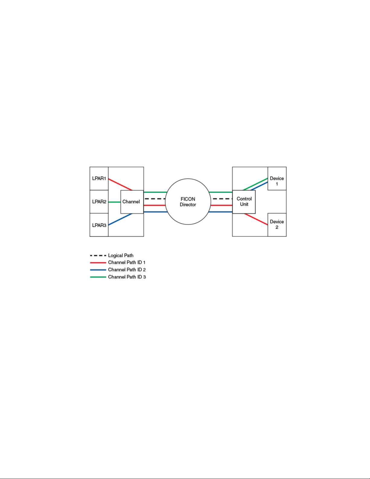
The following figure shows how the traffic in a switched point-to-point configuration flows in a FICON
environment. The logical path of the traffic is defined as frames moving from the channel to the switch
to the control unit. FICON traffic moves from a logical partition (LPAR) and through the channel, through
a Fibre Channel link to the switch through the control unit, and ends at the device. This is also called a
channel path , which is a single interface between a central processor and one or more control units
along which signals and data can be sent to perform I/O requests. The channel path uses the logical
path to traverse the Fibre Channel fabric. The channel path is defined using an ID, called the channel
path ID (CHPID). This information is stored in the Input/Output Definition File (IODF) and may be
dynamically configured using the mainframe feature, zDAC (Discover and Auto Configuration). The
IODF is typically built using the hardware configuration definition (HCD).
FIGURE 1 FICON traffic
FICON concepts
The traffic on the channel path communicates using channel command words (CCWs) that direct the
device to perform device-specific actions, such as seek, read, or rewind. In a FICON environment,
buffer credits are used at the Fibre Channel Protocol (FCP) level for flow control between optically
adjacent ports, while information unit (IU) pacing is the flow control mechanism used by the channel.
There are times when there are no more buffer credits to pass back to the other end of the link and a
frame pacing delay occurs. Frame pacing delay is the number of intervals of 2.5 microseconds that a
frame had to wait to be transmitted due to a lack of available buffer credits. Frame pacing delay
information is reported in the FICON Director Activity Report with the System z RMF feature.
FICON introduces the following concepts:
• FICON Control Unit Port (CUP)
The internal port in a switch that assumes an Fibre Channel (FC) address such that it is the FC
domain ID (DID) used to direct FICON traffic to the FICON Management Server (FMS).
• FICON Manager
Host communication includes control functions such as blocking and unblocking ports, as well as
monitoring and error-reporting functions.
• Hardware configuration definition (HCD)
HCD is an IBM interactive interface application that allows you to define the hardware configuration
for both the processor channel subsystem and the operating system running on the processor.
• Information unit
FICON Administrator's Guide 13
53-1003144-01
Page 16

FICON configurations
A unit of FICON data consisting of from one to four Fibre Channel frames.
• Link Incident Record Registration (LIRR)
The LIRR Extended Link Service (ELS) requests that the recipient add the requesting port to its
list of ports that are to receive a Registered Link Incident Report (RLIR).
• Node
A node is an endpoint that contains information. It can be a computer (host), a device controller,
or a peripheral device, such as a disk array or tape drive. A node has a unique 64-bit identifier
known as the Node_Name. The Node_Name is typically used for management purposes.
• Prohibit Dynamic Connectivity Mask (PDCM) and connectivity attributes
PDCM controls whether communication between a pair of ports in the switch is prohibited.
Connectivity attributes control whether all the communication is blocked for a port.
• Read Record Set (RRS)
RRS is an IBM Channel-initiated CCW command. The Brocade FCIP FICON Acceleration
License allows the emulation of command chains that include this CCW command. The command
is used in IBM z/OS Global Mirror configurations to read updates from a volume in an active
mirroring session.
• Registered Link Incident Report (RLIR)
RLIR ELS provides a way for a node port to send an incident record to another node port.
• Request Node Identification Data (RNID)
RNID ELS acquires the associated node’s identification data, which provides configuration
discovery and management purpose information.
• Resource Measurement Facility (RMF)
Performance monitoring software that gathers transaction data from the environment and
generates performance reports. All Level II reports, which include port statistics, require the
FICON Control Unit Port (CUP) and FICON Management Server (FMS).
• Systems Operations (SysOps)
SysOps provides the ability to monitor and control all subsystems in a sysplex from any system in
the sysplex. This includes controlled startup, controlled shutdown, and automated recovery of
software resources.
• Sysplex
In IBM mainframe computers, a Systems Complex, commonly called a sysplex, allows multiple
processors to be joined into a single unit, sharing the same sysplex name and Couple Data Sets.
• IPL file
The initial program load (IPL) File, located in nonvolatile storage, contains the current, active
configuration settings for the FICON director. If functions to initialize data on the Director during a
POR event. When the "Active=Saved" FICON CUP mode register bit setting is on, any active
configuration in switch memory is automatically saved to the IPL file.
FICON configurations
There are two types of FICON configurations that are supported using Brocade Fabric OS: switched
point-to-point and cascaded topologies.
14 FICON Administrator's Guide
53-1003144-01
Page 17
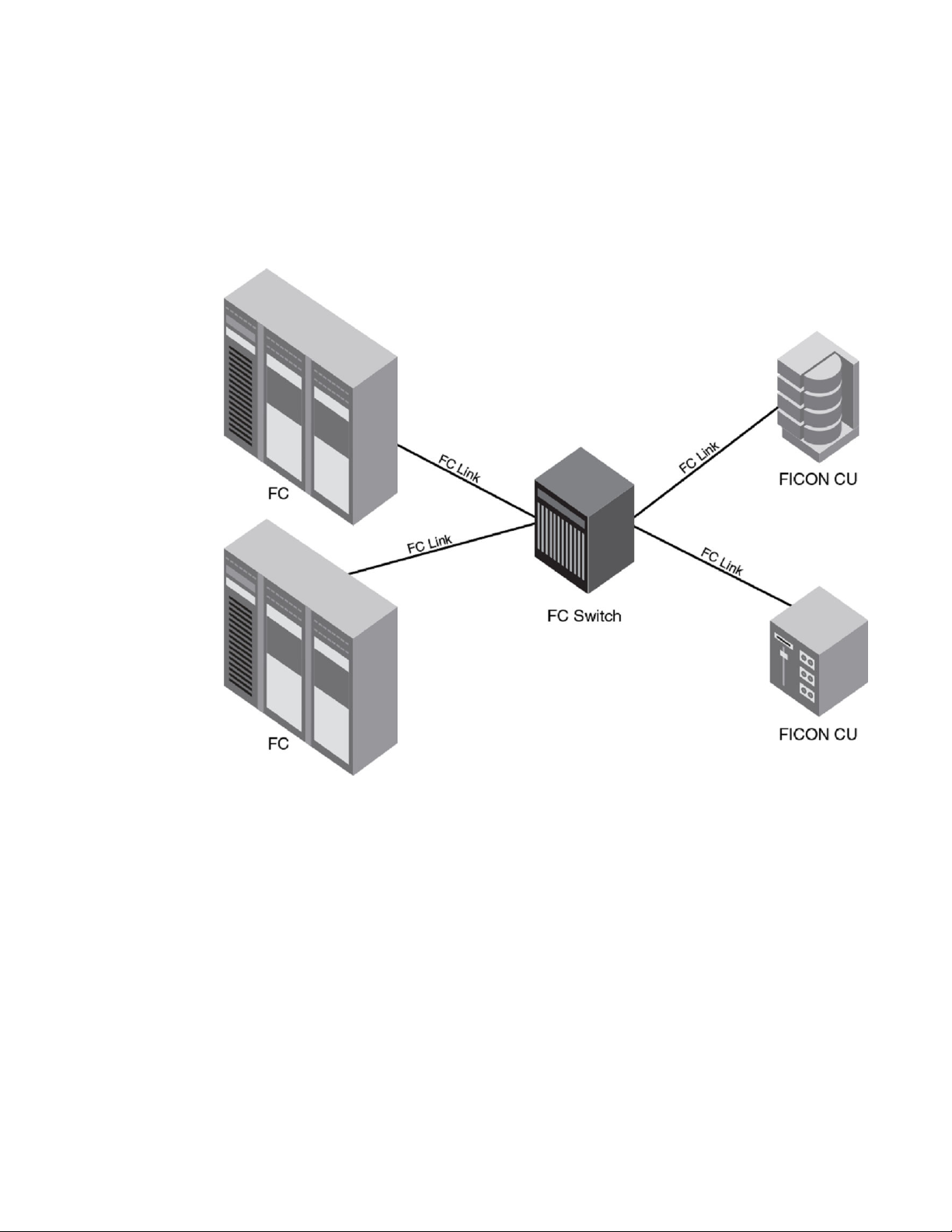
Switched point-to-point
Switched point-to-point
A single-switch configuration is called switched point-to-point allows the channel to use single-byte
addressing.
FIGURE 2 Switched point-to-point FICON
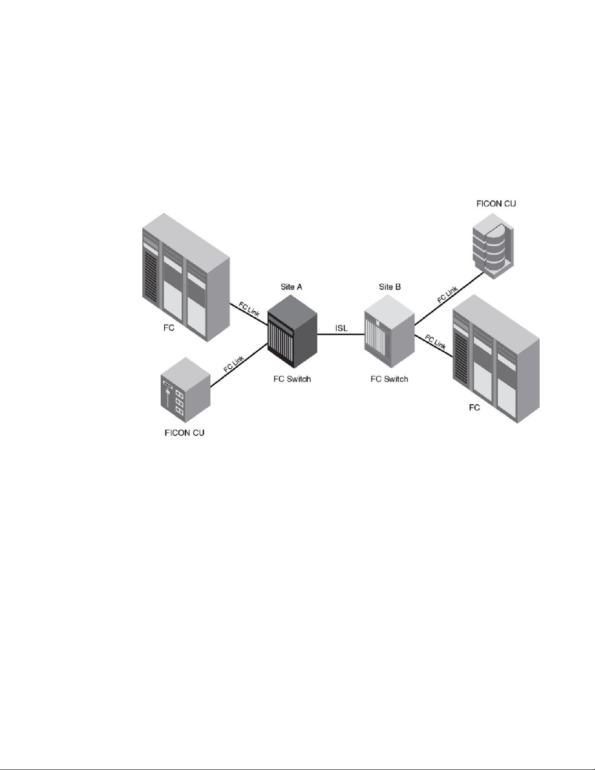
Cascaded FICON
Cascaded FICON refers to an implementation of FICON that uses one or more FICON channel paths in
which the domain ID of the entry switch is different than the domain ID of the switch where the control
unit is attached. Therefore, cascading requires a two-byte link address. Anytime a two-byte link address
is defined on a channel, all link addresses must be two-byte link addresses.
Switches may be interconnected using the following links:
• Traditional Inter-Switch Links (ISLs)
• Inter-Chassis Links (ICLs)
• Fibre Channel over Internet Protocol (FCIP)
The processor interface is connected to one switch (known as the entry switch), while the storage
interface is connected to the other. This configuration is supported for both disk and tape, with multiple
processors, disk subsystems, and tape subsystems sharing the ISLs or ICLs between the switches and
backbones. Multiple ISLs between the switches and backbones are also supported. Cascading between
FICON Administrator's Guide 15
53-1003144-01
Page 18
Qualified FICON cascaded configurations
switches and backbones is also supported. An example of this would be a Brocade DCX 8510-8
Backbone connected to a Brocade 6510.
A cascaded configuration (refer to the following figure) requires two-byte addressing. Two byteaddressing requires a list of authorized switches. This authorization feature, called fabric binding, is
available through the Secure Access Control List feature. The fabric binding policy allows a predefined
list of switches (domains) to exist in the fabric and prevents other switches from joining the fabric. This
type of configuration is described in User security considerations on page 33.
FIGURE 3 Cascaded FICON
There are hardware and software requirements specific to two-byte addressing:
• Both the FICON switches must be Brocade switches.
• The mainframes must be zSeries machines or System z processors: z196, z114, z800, 890, 900,
990, z9 BC, z9 EC, z10 BC, EC, and zEC12. Cascaded FICON requires 64-bit architecture to
support the two-byte addressing scheme. Cascaded FICON is not supported on 9672 G5/G6
mainframes.
• z/OS version 1.4 or later, or z/OS version 1.3 with required Program Temporary Fixes (PTFs) and
Microcode Loads (MCLs) to support two-byte link addressing (DRV3g and MCL (J11206) or later)
is required.
• Switch configuration requirements:
‐ Make sure that E_D_TOV is the same on all switches in the fabric (typically, this is not
changed from the default)
‐ Make sure that R_A_TOV is the same on all switches in the fabric (typically, this is not
changed from the default)
‐ Configure insistent Domain ID (IDID)
‐ Configure fabric binding (strict SCC policy)
Qualified FICON cascaded configurations
Not all fibre channel fabrics are qualified for FICON. Cascaded FICON configurations are limited to
well-controlled paths. Only the channel paths illustrated in this section are supported for FICON. The
16 FICON Administrator's Guide
53-1003144-01
Page 19
Extended fabric configurations
resulting fabric scenario after ISL failures must not result in an unsupported configuration. When
physical cabling is not practical to enforce these configurations, zoning or Traffic Isolation zoning (TI
zoning) with failover disabled may be used to ensure unsupported fabrics cannot be formed. Note that
these restrictions apply to logical switches and not the chassis.
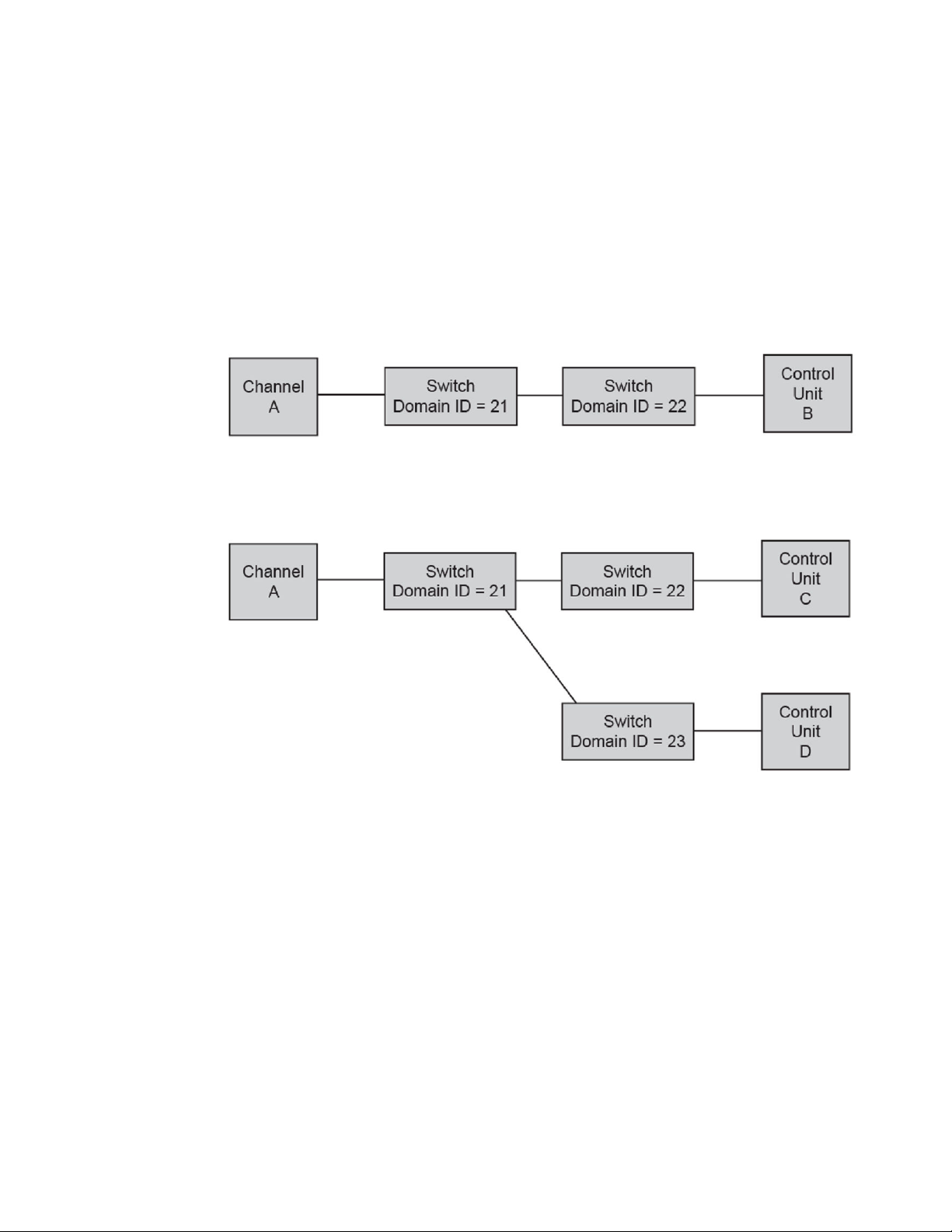
The following figures show two cascaded configurations. These configurations require Channel A to be
configured for two-byte addressing and require IDID and fabric binding. It is recommended that there be
only two domains in a path from a FICON Channel interface to a FICON Control Unit interface. There
are exceptions to the two-domain rule in extended fabric configurations. Refer to Extended fabric
configurations on page 17 for examples.
FIGURE 4 Cascaded configuration, two switches
The following figure illustrates multiple switches cascaded off of switch 21. As long as there is only one
hop from channel to control unit, the configuration is supported.
FIGURE 5 Cascaded configuration, core-edge architecture
Extended fabric configurations
Switches in cascaded configurations may be connected through interchassis links (ICLs), interswitch
links (ICLs), and FCIP. Connection using FCIP is through Fibre Channel extension devices, such as
7800 switches and FX8-24 blades. Following are example configurations.
For more information on long distance and extended fabrics, refer to the Fabric OS Administrator's
Guide. For more information on FCIP and extension products, refer to the Fabric OS FCIP
Administrator's Guide.
FICON Administrator's Guide 17
53-1003144-01
Page 20
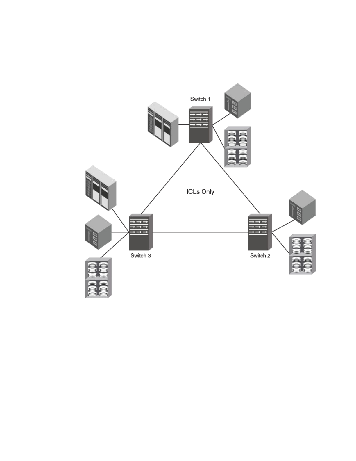
Introducing FICON
The following figure illustrates a multi-hop ICL triangle configuration that uses ICLs. Note that three
switches are connected through ICLs only.
FIGURE 6 Multi-hop ICL triangle
18 FICON Administrator's Guide
53-1003144-01
Page 21
Introducing FICON
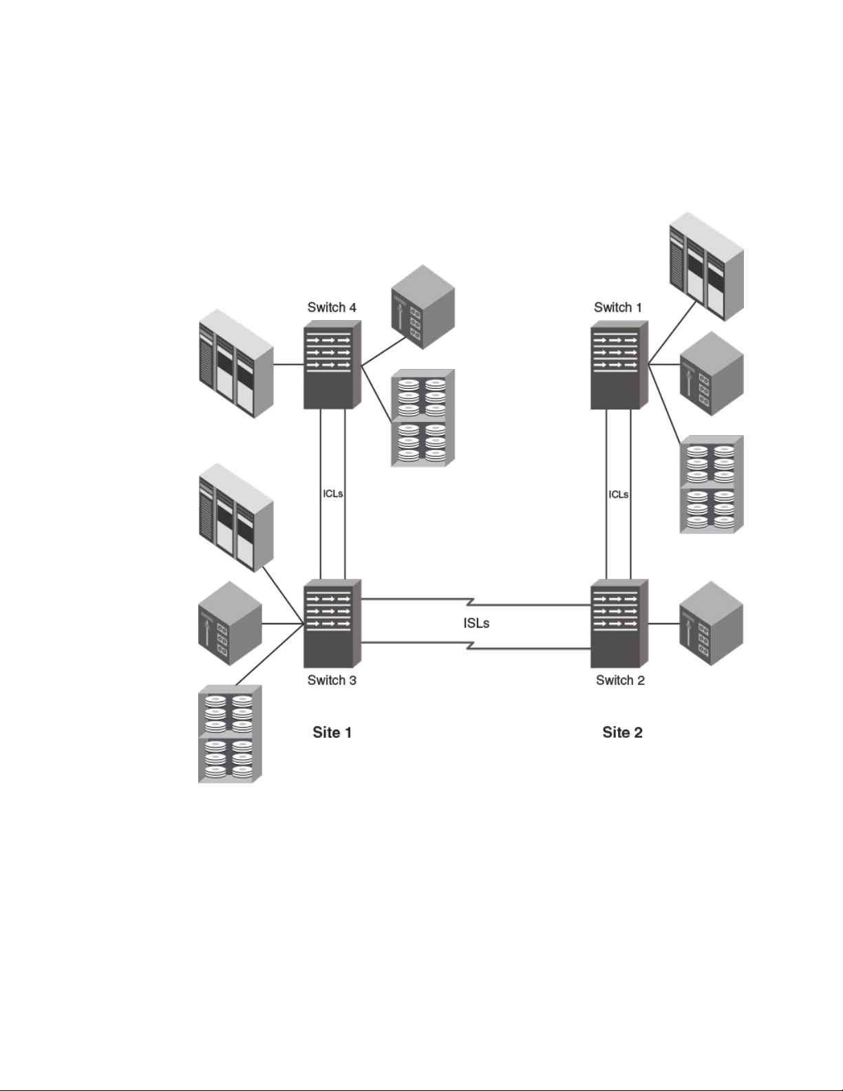
The following figure illustrates a multi-hop configuration that uses ICLs and ISLs. This configuration is
supported with or without switches 4 or 1. All switches must be all generation (Gen) 4 or all Gen 5. You
cannot mix Gen 4 and Gen 4 on ICL connections.
FIGURE 7 Multi-hop configuration with ICLs
The following figure illustrates a multi-hop configuration that uses ICLs and FCIP. The two 7800
switches are for ISL extension only using FCIP. Channel or control unit connections are not permitted.
These switches may be replaced with an FX8-24 blade installed in directors. This configuration can be
FICON Administrator's Guide 19
53-1003144-01
Page 22
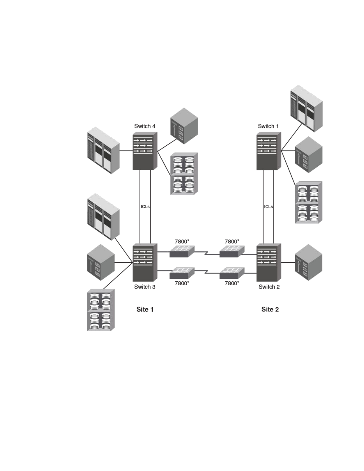
Introducing FICON
supported with or without switches 4 or 1. All switches must be Gen 4 or Gen 5. You cannot mix Gen 4
and Gen 5 switches with ICLs.
FIGURE 8 Multi-hop with ICLS and FCIP
20 FICON Administrator's Guide
53-1003144-01
Page 23

Introducing FICON
The following figure illustrates a configuration that uses FCIP between 7800 switches that are used as
routers only, for ISL extension. Channel or control unit connections are not permitted. The 7800
switches may be replaced with FX8-24 blades installed in directors.
FIGURE 9 FCIP with 7800 switches as routers only
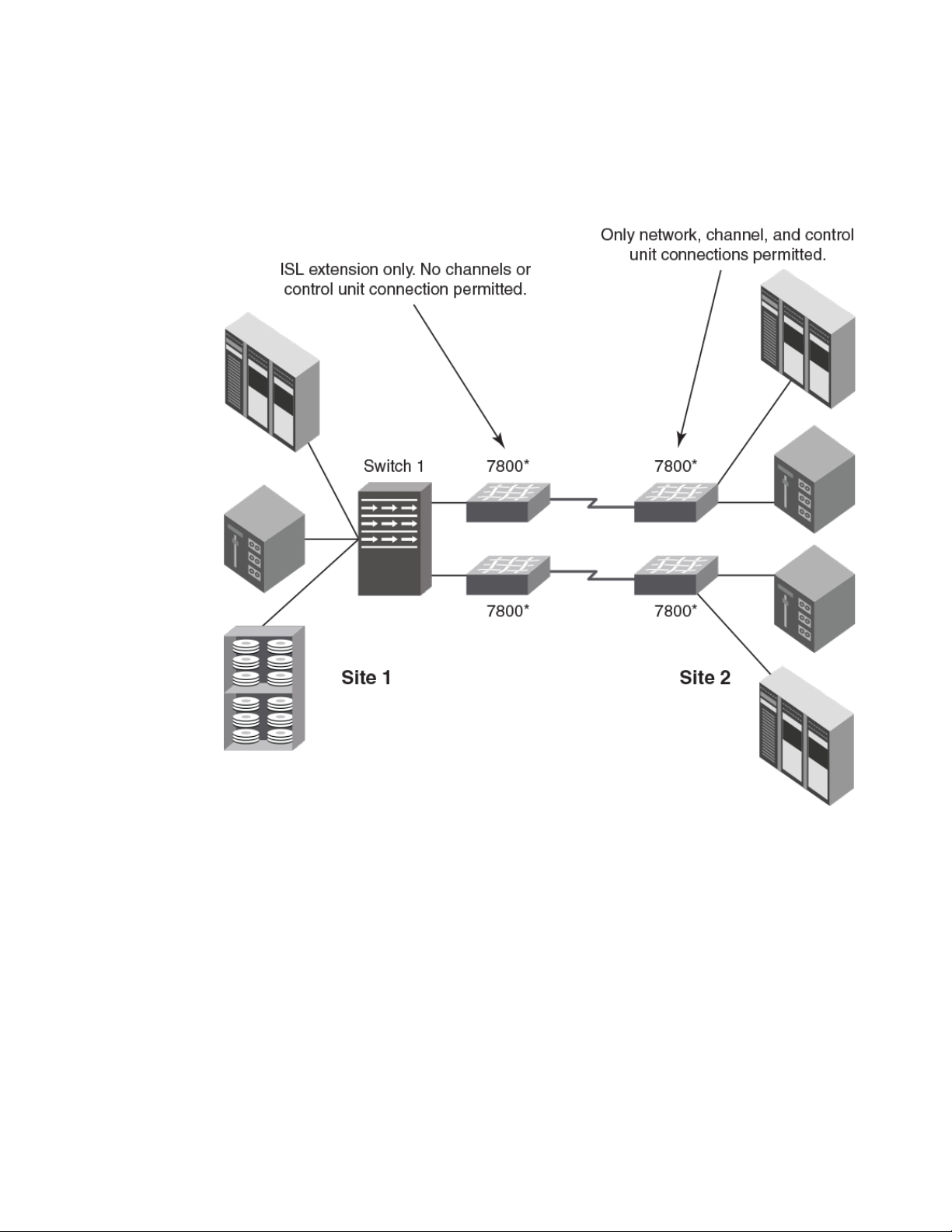
The following figure illustrates a configuration that uses cascaded FCIP with four 7800 switches. The
7800 switches at site 1 are used for ISL extension only. Channel or control unit connections are not
FICON Administrator's Guide 21
53-1003144-01
Page 24
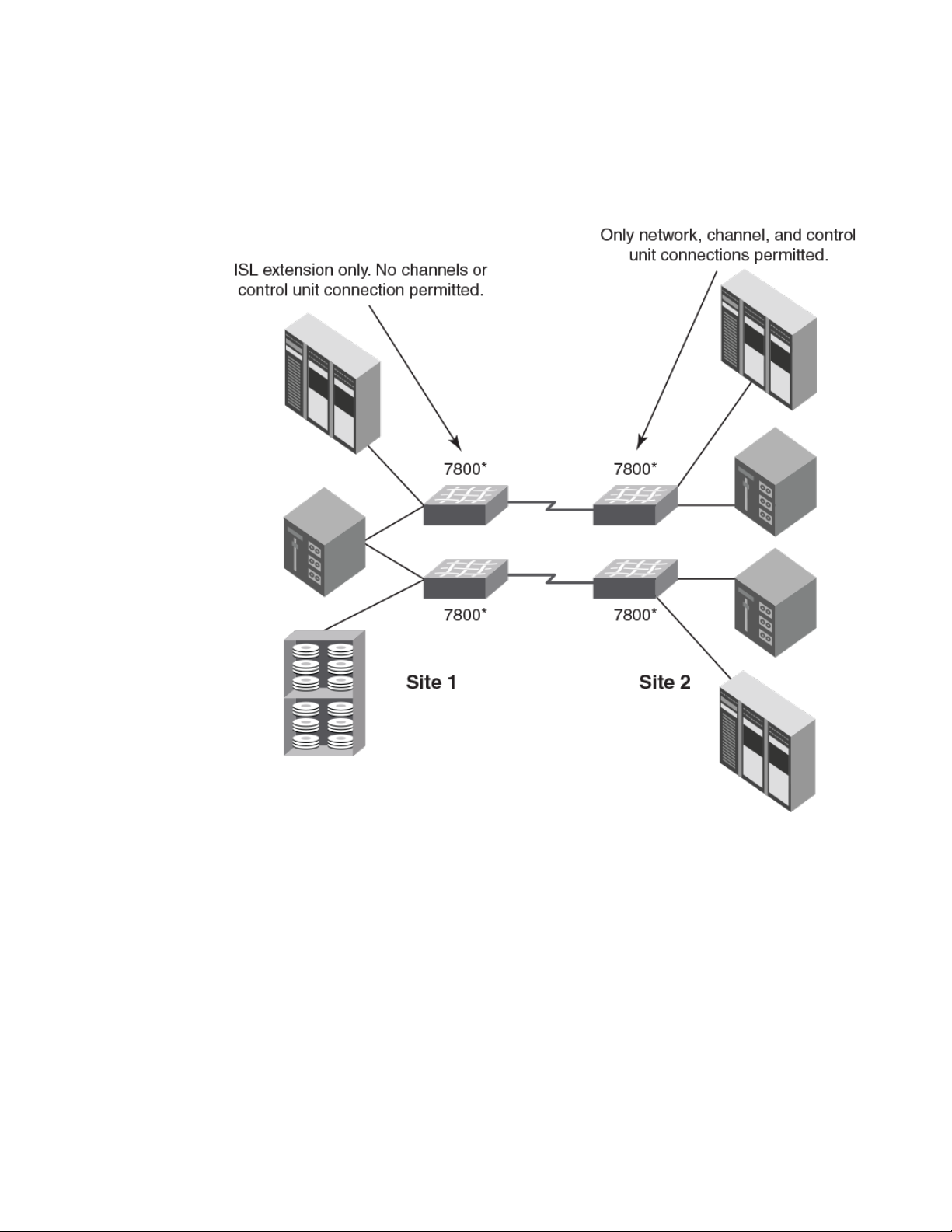
Introducing FICON
permitted. The 7800 switches at site 2 are only for network, channel, and control unit connections. The
7800 switches on either site may be replaced with the FX8-24 blades installed in directors.
FIGURE 10 Cascaded configuration using FCIP and 7800 switches
The following figure illustrates a cascaded configuration that uses FCIP and 7800 switches as edge
switches. At site 1, the 7800 switches are used for ISL extension only. Channel or control unit
connections are not permitted. At site 2, only channel, and control unit connections are permitted on
22 FICON Administrator's Guide
53-1003144-01
Page 25
Access control in FICON
the 7800 switches. The 7800 switches at either site may be replaced with the FX8-24 blades installed in
directors.
FIGURE 11 Cascaded configuration using FCIP and 7800 edge switches
Access control in FICON
Zoning is used to control access in a FICON environment. A zone consists of a group of ports or
WWNs. Connectivity is permitted only between connections to the switch that are in the same zone.
There are three types of zoning: WWN, port, and domain index zoning. A zone configuration includes at
least one zone. In open systems environments and in more complex FICON deployments, the zone
configuration contains multiple zones. Although domain index zoning is supported, WWN zoning for
Quality of Service (QoS) is recommended in environments where N_Port ID Virtualization (NPIV) is
deployed. For more information on how to implement QoS domain index zoning in your fabric, refer to
the "QoS zones" section of the Fabric OS Administrator's Guide for details.
When zoning changes occur, Registered State Change Notification (RSCN) messages are sent out
throughout the zone. RSCNs are part of the low-level Fibre Channel Protocol that alerts channels and
FICON Administrator's Guide 23
53-1003144-01
Page 26
Cascaded zoning
devices to changes in the fabric. Using multiple smaller zones instead of one large zone helps
alleviate the need for channels and device interfaces to process RSCNs that are not relevant.
NOTE
Session-based zoning enforcement is not recommended on a FICON switch. For more information on
session-based zoning enforcement, refer to the Fabric OS Administrator's Guide.
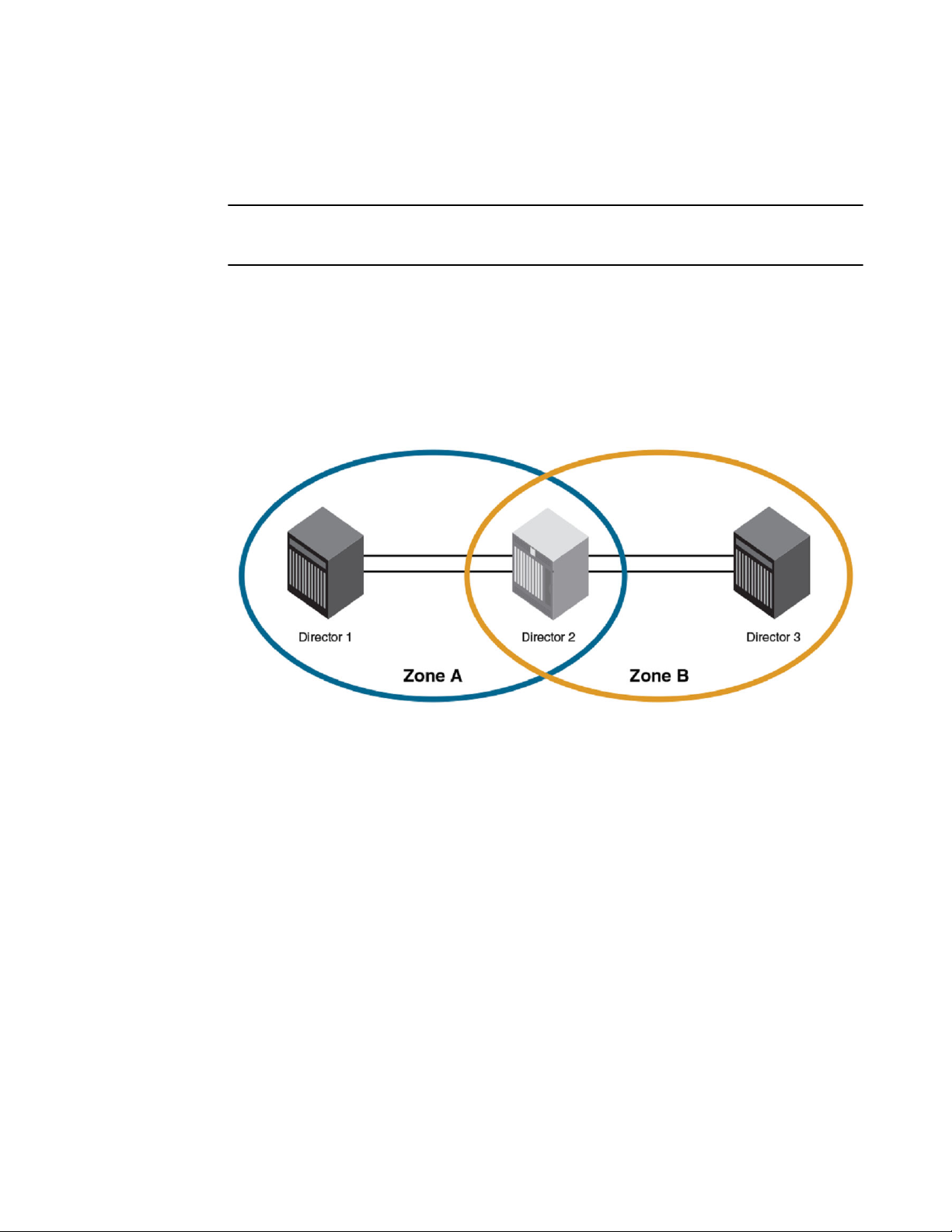
Cascaded zoning
The figure below illustrates multiple sites sharing the same disaster-recovery site. Each switch or
Backbone at a remote site, labeled Director 1 and Director 31, can pass traffic to Director 2, but no
traffic is permitted between Zone A and Zone B.
FIGURE 12 Simple cascaded zoning
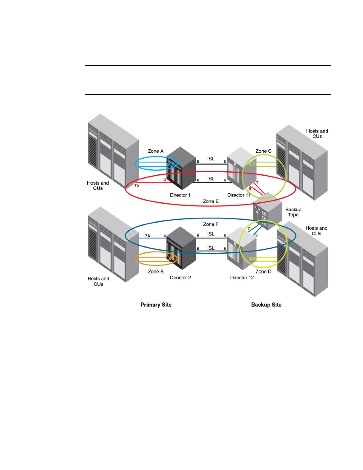
The figure below illustrates the multiple zoning concepts that can be used to restrict traffic. Any host
channel at the Backup Site (connected to Director 11 or Director 12) can connect to the backup tape
contained within the same zone. Notice that no more than a single hop is ever allowed and only
Channel Path Identifiers (CHPIDs) 79 and 7A on the Primary Site can connect to the backup tape.
Furthermore, CHPIDs 79 and 7A can only connect to the backup tape at the Backup Site.
24 FICON Administrator's Guide
53-1003144-01
Page 27
Introducing FICON
NOTE
Zoning does not replace the need to set up the connectivity from the host to storage control units in the
HCD or Input/Output Configuration Program (IOCP). For more information on zoning, refer to the Fabric
OS Administrator's Guide.
FIGURE 13 Complex cascaded zoning
Zone A (Blue): Any CHPID connected to Director 1, except CHPID 79, can get to any control unit
connected to Director 1. The zone includes all ports in Director 1 except ports 4, 5, and 6.
Zone B (Orange): Any CHPID connected to Director 2, except CHPID 7A, can get to any control unit
connected to Director 2. The zone includes all ports in Director 2 except ports 4, 5, and 6.
Zone C (Green): Any CHPID connected to Director 11 can get to any control unit connected to Director
11. The zone includes all ports in Director 11 except ports 5 and 6. Adding ports 5 and 6 to the zone, so
that all ports in the switch or Backbone are in the same zone, would not affect permitted connectivity
and may be a more practical alternative.
Zone D (Yellow): Any CHPID connected to Director 12 can get to any control unit connected to Director
12. The zone includes all ports in Director 12 except ports 5 and 6, which are used for ISLs.
Red Zone E: CHPID 79 can talk only to the remote tape connected to ports 7 and 8 on Director 11. The
zone includes port 4 of Director 1 and ports 7 and 8 of Director 11. Either ISL can be used.
Purple Zone F: CHPID 7A can talk only to the remote tape connected to ports 7 and 8 on Director 12.
The zone includes port 4 of Director 2 and ports 7 and 8 of Director 12. Either ISL can be used.
FICON Administrator's Guide 25
53-1003144-01
Page 28

Error reporting
Error reporting
Non-implicit link incidents (such as Fabric OS recognized or bit error rate threshold exceeded) and
implicit link incidents (such as FRU failure) are reported to registered listeners on the local switch. The
RMF 74-7 record (FICON Director Activity Report, which is the same RMF record containing the
average frame pacing delay information) reports port errors, which in turn are also reported back to the
mainframe host management consoles.
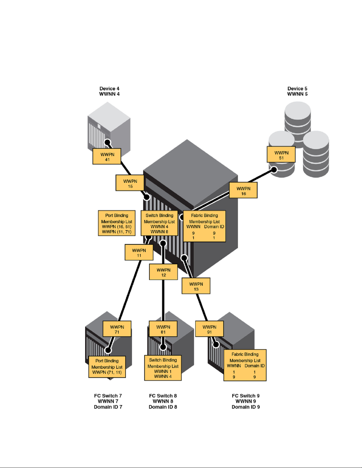
Secure access control
Binding is a method used to prevent devices from attaching to the switch or backbone. Secure Access
Control Lists (ACLs) provides the following fabric, switch, and port binding features:
• Fabric binding is a security method for restricting switches within a multiple-switch fabric. Brocade
recommends using fabric binding for cascaded FICON. SCC ACLs with strict fabric-wide
consistency are required for FICON fabric binding.
• Switch binding is a security method for restricting devices that connect to a particular switch or
backbone. If the device is another switch, this is handled by the SCC policy. If the device is a host
or storage device, the device connection control (DCC) policy binds those devices to a particular
switch. Policies range from completely restrictive to reasonably flexible, based upon customer
needs. SCC ACLs with strict fabric-wide consistency are necessary for FICON switch binding.
• Port binding is a security method for restricting host or storage devices that connect to particular
switch ports. The DCC policy also binds device ports to switch ports. Policies range from
completely restrictive to reasonably flexible, based on customer needs.
26 FICON Administrator's Guide
53-1003144-01
Page 29
Introducing FICON
The figure below demonstrates the three types of binding you can use depending on the security
requirements of your fabric.
FIGURE 14 Types of binding for access control
FICON Administrator's Guide 27
53-1003144-01
Page 30

FICON commands
FICON commands
NOTE
The Fabric OS CLI supports only a subset of the Brocade management features for FICON fabrics.
The full set of FICON CUP administrative procedures is available using the Brocade Network Advisor
and Web Tools software features. You can also use an SNMP agent and the FICON Management
Information Base (MIB).
The table below summarizes the Fabric OS CLI commands that can be used for managing FICON
fabrics. For detailed information on these commands, refer to the Fabric OS Command Reference.
Command Description
Standard Fabric OS commands
Fabric OS commands related to FICON TABLE 1
bladeSwap
configure
configUpload
firmwareShow
licenseAdd
licenseRemove
licenseShow
licenseSlotCfg
Swaps the area numbers for matching port pairs of
two blades.
Changes a variety of switch configuration settings,
including setting the domain ID and the insistent
mode.
Backs up the current FOS feature and switch
configuration, but does not back up FMS or FICONspecific configuration such as IPL file, active
configuration, mode register, and host data.
Displays the current version of the firmware.
Adds a license to the switch. The license key is casesensitive and must be entered exactly.
Removes a license from the switch. Note that FMS
mode must be disabled before removing the FICON
license.
Displays current license keys, along with a list of
licensed products enabled by these keys.
Enables and displays slot-based licenses for a switch
chassis. Note that for a switch without blades, such as
the 7800 Extension Switch, slot 0 is used as the slotbased license target. For blades, slot numbers are
based on the switch chassis numbering scheme. A
license key with the specified capacity must be
installed with the licenseAdd command before you
can enable a feature on a specified slot with this
command.
portAddress
28 FICON Administrator's Guide
Binds the 16-bit address to the lower two bytes of a
port 24-bit Fibre Channel address. Also unbinds the
currently bound address for the specified port.
53-1003144-01
Page 31

Fabric OS commands related to FICON (Continued)TABLE 1
Command Description
Introducing FICON
portSwap Swaps ports. Note that the portswap --restore
command restores swapped ports to an unswapped
state.
portSwapDisable Disables the portSwap feature. The portSwap
command cannot be used after this feature is
disabled. The disabled state is persistent across
reboots and power cycles. Enabling or disabling the
portSwap feature does not affect previously
performed portSwap operations.
portSwapEnable
portSwapShow
supportShowCfgEnable ficon
Commands specific to FICON
ficonClear rlir
ficonClear rnid
ficonCfg --set LIRR portnumber
Enables the portSwap feature.
Displays information about swapped ports.
Turns on logging of FICON information on the switch.
Removes all RLIR records from the local RLIR
database.
Removes all outdated RNID records from the local
RNID database.
Sets the current LIRR device port number persistently.
ficonCfg --reset LIRR portnumber
ficonHelp
ficonCupSet fmsmode enable | disable |reset
ficonCupSet modereg bitname 0 | 1
ficonCupSet MIHPTO seconds
ficonCupSet CRP PID CHID
ficonCupShow DD_LOG
Clears the currently configured LIRR port number.
Displays a list of FICON support commands.
Enables, disables, or resets FICON Management
Server (FMS) mode.
CAUTION
Use the ficonCupSet fmsmode reset option
only under direction from technical support
personnel. Indiscriminate use can disrupt CCW
processing and create errors at the host.
Sets FICON-CUP mode register bits.
Sets missing interrupt handler primary timeout
(MIHPTO) values.
Sets the current reporting path (CRP).
Displays the log information associated with the last
diagnostic command processed by the CUP.
FICON Administrator's Guide 29
53-1003144-01
Page 32

Link and FC addressing
Fabric OS commands related to FICON (Continued)TABLE 1
Command Description
ficonCupShow diag_info
ficonCupShow fmsmode
ficonCupShow hlthchk_log
ficonCupShow modereg bitname
ficonCupShow MIHPTO
ficonCupShow LP
ficonShow lirr fabric
ficonShow rlir fabric
ficonShow rnid fabric
Displays the diagnostic interval setting and related
statistic sampling information for diagnostic
information collected by the CUP.
Displays the current FMS mode setting.
Displays health check logs for the logical switch.
Displays FICON-CUP mode register bits.
Displays MIHPTO values.
Displays the CUP logical path and error-reporting path
information.
Displays registered listeners for link incidents for the
local switch or for the fabric, if specified.
While all FICON channels register as "conditional"
recipients of registered link incident reports (RLIRs)
and are added to the switch LIRR database, only one
channel per switch is selected to forward reports to the
host. The command output displays all channels which
have registered and indicates which node on each
switch is selected to generate reports to the host.
Displays node identification data for all devices
registered with the local switch or all devices
registered with all switches defined in the fabric, if
specified.
ficonShow rnid port
ficonShow rnid table
ficonShow switchrnid fabric
Displays node identification data for a specified port.
Displays the local node identification database in
tabular format.
Displays node identification data for the local switch or
for the fabric, if specified.
For limitations and considerations for using Fabric OS commands with FMS mode enabled, refer to
Fabric OS command limitations and considerations on page 57.
Link and FC addressing
To understand the addressing mode requirements and restrictions for FICON, it is important to
understand the relationship between the link address and the FC address. Understanding this
relationship is also valuable for troubleshooting paths.
30 FICON Administrator's Guide
53-1003144-01
Page 33

Domain ID
The following figure represents components of link and FC addresses that are explained in this section.
FIGURE 15 Link and FC address components
Domain ID
Although you enter the domain ID in decimal format when configuring a switch, it is represented in
hexadecimal formal in the FC address.
For single-byte addressing, the domain area returned from the switch where the channel logs in is used
for the FC address. Therefore, the channel and control unit must be in the same logical switch. With
two-byte link addressing, the most significant byte of the link address is used for the domain area of the
FC address. Once two-byte link addressing is defined for a channel, all link addressing for that channel
must use two-byte link addressing.
Port area
The port area address is the single-byte link address or the least significant byte of a two-byte link
address. The link address is entered in the HCD in hexadecimal format and is represented in
hexadecimal in the FC address.
ALPA
The Arbitrated Loop Physical Address (ALPA) was originally used in fibre channel for loop devices.
Currently, the ALPA is used for N_Port ID Virtualization (NPIV), which allows multiple WWNs to log in to
the same switch port. The ALPA determines the logical entity to which frames belong. This is how
virtual servers using zLinux or zVM can share the same channel. Because the DCX and DCX 8510-8
Backbones can have up to 512 ports, the upper two bits of the ALPA are used in certain addressing
modes.
FICON does not use the ALPA byte. However, the ALPA is a required byte in the FC address. The
channel completes the FC address for a control unit link address by acquiring the ALPA that the switch
returned to the channel when the channel logged in. This is why the ALPA must be the same for both
the channel port and the control unit port. This is also the reason why 10-bit addressing mode cannot be
used for FICON (refer to Addressing modes on page 44).
FICON Administrator's Guide 31
53-1003144-01
Page 34

ALPA
32 FICON Administrator's Guide
53-1003144-01
Page 35

Administering FICON Fabrics
● User security considerations........................................................................................... 33
● Meeting high-integrity fabric requirements...................................................................... 33
● Preparing a switch for FICON......................................................................................... 36
● Configuring switched point-to-point FICON.....................................................................37
● Configuring cascaded FICON......................................................................................... 41
● FCR and FICON cascading............................................................................................ 42
● FICON and FICON CUP in Virtual Fabrics..................................................................... 43
● Addressing modes.......................................................................................................... 44
● Disabling and enabling ports - persistent states............................................................. 46
● Clearing the FICON management database...................................................................47
● Automating CS_CTL mapping........................................................................................ 47
● FICON best practices......................................................................................................49
● Latency guideline............................................................................................................ 50
User security considerations
To administer FICON, you must have one of the following roles associated with your login name on the
switch:
• Admin
• Operator
• SwitchAdmin
• FabricAdmin
The User and BasicSwitchAdmin roles are view-only. The ZoneAdmin and SecurityAdmin roles have no
access.
In an Admin Domain-aware fabric, if you use the FICON commands (ficonShow, ficonClear,
ficonCupShow, and ficonCupSet) for any Admin Domain other than AD0 and AD255, the current
switch must be a member of that Admin Domain. The output is not filtered based on the Admin Domain.
In Virtual Fabrics, these commands apply to the current logical or specified switch only.
Meeting high-integrity fabric requirements
In a cascaded switch configuration, FICON channels use an Extended Link Service Query Security
Attributes (ELS QSA) function to determine whether they are connected to a high-integrity fabric. Each
switch in a high integrity fabric must have the following attributes configured:
• An insistent domain ID (IDID)
• A valid SCC policy (configured and activated)
• A fabric-wide consistency policy greater to or equal than switch connection control - strict mode
(SCC:S)
FICON Administrator's Guide
53-1003144-01
33
Page 36

Enabling the insistent domain ID
NOTE
You enable the fabric-wide consistency policy on the fabric once the switch joins the fabric.
NOTE
If FMS mode is enabled before upgrading to v7.3.0, IDID, SCC_Policy, and SCC:S will be
validated and the firmware attempt failed if either are incorrect. If validation is successful, HIF
mode will automatically enable when the firmware installs.
If a FICON channel tries to connect to a fabric switch without these features configured, the channel
segments from the fabric.
Once these features are configured, you must enable the switch in High-Integrity Fabric (HIF) mode
using the Fabric OS configure command. This verifies the required features are set and locks the
configuration to ensure connection with the FICON channel. Once the HIF mode is set, you cannot
change the IDID, fabric-wide consistency policy, and SCC policy without disabling HIF mode.
Following are considerations for using HIF mode:
• You must enable HIF mode to enable FMS mode.
• Before a Fabric OS downgrade, you must disable HIF mode. Note that this operation is not
recommended for FICON and should only be used when downgrading firmware. You will receive
a warning to this effect if FMS mode is enabled. If HIF is disabled, any new channel initialization
would fail as the Query Security Attribute (QSA) reply from the switch to the channel will fail. The
existing channel will continue to operate, however.
• Before a Fabric OS upgrade, be sure the switch has appropriate IDID, fabric-wide consistency
policy, SCC policy settings are enabled so that HIF mode can enable when the firmware installs.
The following instructions are provided in this section to configure a switch as part of a high-integrity
fabric:
• Enabling insistent domain ID on page 34
• Creating and activating the SCC policy on page 34
• Enabling the fabric-wide consistency policy on page 35
• Enabling High-Integrity Fabric mode on page 35
Enabling the insistent domain ID
To enable the insistent domain ID, complete the following steps for each switch in the fabric.
1. Connect to the switch and log in using an account assigned to the admin role.
2. Enter the configure command and step through the interactive prompts.
a) At the "Fabric parameters" prompt, type y.
b) At the "Insistent Domain ID Mode" prompt, type y.
Creating and activating the SCC policy
Creating a switch connection control (SCC) policy defines switches allowed in the fabric.
To configure and activate an SCC policy, use the following steps.
1. Connect to the switch and log in.
2. Perform one of the following steps:
34 FICON Administrator's Guide
53-1003144-01
Page 37

Enabling the fabric-wide consistency policy
• Enter the secpolicycreate command to add all switches in the fabric, if they are connected.
secpolicycreate "SCC_POLICY","*"
• Enter the secpolicyadd command to add one or more members to an existing policy. The
following command is an example of adding a member using device WWNs.
secpolicyadd "SCC_POLICY","wwn1;wwn2"
3. Enter the secpolicyactivate command to activate the currently defined SCC policy.
This activates the policy set on the local switch or all switches in the fabric, depending on the
configured fabric-wide consistency policy.
Enabling the fabric-wide consistency policy
Enable the fabric-wide consistency policy after all the switches have joined the merged fabric. If there
are fabric-wide data distribution (FDD) conflicts on any of the ISLs, disable the fabric-wide consistency
policy on each switch in the fabric.
Once the fabric has merged successfully (use fabricShow to verify), enter the following command.
fddcfg --fabwideset "SCC:S"
Following are considerations for enabling the fabric-wide security policy:
• SCC:S enforces strict mode, which is required for FICON.
• Fabric-wide consistency policy cannot be set to strict mode on an edge fabric if the fabric connects
to a FCR, although FCR front and translate domains can exist in the fabric. For more information,
refer to FCR and FICON cascading on page 42.
Enabling High-Integrity Fabric mode
Setting High-Integrity Fabric (HIF) mode on a switch verifies that the switch meets high-integrity fabric
requirements through the channel's Extended Link Services Exchange Query Security Attributes (ELS
QSA) function.
For a list of high-integrity fabric requirements for switches, refer to Meeting high-integrity fabric
requirements on page 33. Setting HIF mode locks the IDID, fabric-wide consistency policy, and SCC
policy settings to ensure that the fabric is of high integrity so that it can connect with the FICON
channel. You cannot change these settings without disabling HIF mode.
NOTE
HIF mode must be enabled to enable FMS mode.
To enable HIF mode, use the following steps.
1. Connect to the switch and log in using an account assigned to the admin role.
2. Enter the configure command and step through the interactive prompts.
a) At the "Fabric parameters" prompt, type y.
b) At the "High Integrity Fabric Mode" prompt, type y.
If HIF configuration requirements have not been met, an error message describes what you must
configure for the command to succeed. For example, the following message states that an IDID, SCC
policy or fabric-wide consistency policy have not been configured for the switch. Perform additional
configuration if required, then enable HIF mode.
Error: Unable to set HIF Mode. No valid IDID settings,
SCC policy and/or Fabric wide(SCC:S) configuration
FICON Administrator's Guide 35
53-1003144-01
Page 38

Using other security commands
Using other security commands
The following commands are some other security-related commands that you might find useful.
Disabling the fabric-wide consistency policy
To disable the fabric-wide consistency policy, enter the fddcfg --fabwideset command.
Displaying the fabric-wide consistency policy
To display fabric-wide consistency policy information, enter the fddcfg --showall command.
Displaying the current security policy
To display the current security policy, enter the secpolicyshow command.
Deleting the SCC_POLICY
Enter the secpolicydelete "SCC_POLICY" command if you get messages that the E_Port is in a
security violation state.
Recovering the E_Port
Enter the following commands for each switch if the E_Port is down:
secpolicyactivate
portenable n
NOTE
For more detailed information on commands and command output referenced in this section, refer to
the Fabric OS Command Reference.
Preparing a switch for FICON
Use the following steps to verify and prepare a switch for use in a switched point-to-point FICON
environment. A single-switch configuration does not require insistent domain IDs (IDIDs) or fabric
binding, provided that connected channels are configured for single-byte addressing. However, you
should configure an IDID to ensure that domain IDs are maintained.
1. Connect to the switch and log in using an account assigned to the admin role.
2. Verify the management IP addresses have been set up.
3. Verify the switches can be seen by your management tool.
4. Verify the switches have the correct version of Fabric OS.
5. Add feature keys, if applicable.
6. Enter the configUpload command to save a baseline of the switch configuration.
36 FICON Administrator's Guide
53-1003144-01
Page 39

Cascaded FICON and two-byte addressing considerations
Cascaded FICON and two-byte addressing considerations
The following are considerations when installing a switch in a FICON environment where two-byte
addressing is used. Two-byte addressing is always used in cascaded environments but may be used in
single-switch fabrics as well. Making changes to your switch or backbone may require scheduled
downtime.
• All fabric operating parameters, such as timeout values, must be the same. If you have not made
any changes outside the scope of this document, there is nothing additional to consider regarding
these parameters.
• The domain IDs of all switches must be unique and insistent.
• Although not required, it will be easier to configure the security policies if the zoning matches.
Ensuring proper zoning configuration, ISL connections, and that switches and backbones have
merged into a fabric will also make the process of setting the security attributes much easier.
Configuring switched point-to-point FICON
This section provides detailed steps and commands to configure a switch for point-to-point FICON
operation. The following steps assume that you have used your hardware reference manual to perform
the initial setup of the switch and have performed all the steps from Preparing a switch for FICON on
page 36.
For basic steps and commands in a checklist format to quickly configure a switch for fabric and possible
FICON operation, refer to the Basic Switch Configuration chapter, then return to this chapter for detailed
FICON configuration procedures.
Use the worksheet in the Configuration Information Record appendix to record your configuration
information.
Refer to FICON commands on page 28 for a list of FICON-related Fabric OS commands.
CAUTION
Configuring the switch for FICON is a disruptive process. The switch must be disabled to
configure switch parameters.
1. Connect to the switch and log in using an account assigned to the admin role.
2. Enter the switchDisable command. You will need to disable the switch to access all the switch
parameters.
3. Configure the switch and chassis name, if applicable.
4. Set the routing policy by entering the aptPolicy command.
Port-based routing (PBR) and device-based routing (DBR) are qualified for System z; however,
reference your system qualification letter for current support information. The recommended policy
is DBR (aptPolicy 2).
If FICON Emulation features (IBM z/OS Global Mirror or Tape Pipelining) are enabled on an FCIP
Tunnel in the switch, PBR or (aptPolicy 1) must be used.
5. Configure Dynamic Load Sharing.
The recommended best practice is to enable Dynamic Load Sharing (DLS); however, DLS is only
supported when Lossless is enabled.
• To enable Lossless with DLS, use the dlsSet --enable -lossless command.
• If Lossless will not be used, use the dlsReset command.
FICON Administrator's Guide 37
53-1003144-01
Page 40

Administering FICON Fabrics
NOTE
If Lossless DLS is not enabled, the routing policy must be port-based routing (aptPolicy 1).
6. Set In-Order Delivery using the iodSet command.
7. Configure the switch parameters using the configure command and enter the responses shown
in the table below when prompted. (Items in italics are top-level parameters.)
FICON switch parameters TABLE 2
Parameter Response Comment
Fabric parameter Yes Prompts for the fabric parameters.
Domain The domain ID is the switch address. The recommended best practice is to
R_A_TOV 10000 Do not change. The Resource Allocation TimeOut Value (R_A_TOV) is
E_D_TOV 2000 The Error Detect TimeOut Value (E_D_TOV) is a timeout value entered in
WAN_TOV 0 Wide-Area Network TimeOut Value (WAN_TOV) is set in milliseconds.
MAX HOPS 7 This parameter should not be confused with the one- hop FICON
set the switch address and domain ID to be the same. The domain ID is
entered in decimal, so a switch address of hexadecimal 0x22 would have a
domain ID of decimal 34.
entered in milliseconds. This works with the variable E_D_TOV to
determine switch actions when presented with an error condition.
Allocated circuit resources with detected errors are not released until the
time value has expired. If the condition is resolved prior to the timeout, the
internal timeout clock resets and waits for the next error condition.
milliseconds. This timer is used to flag a potential error condition when an
expected response is not received within the set time limit. If the time for
an expected response exceeds the set value, then an error condition
occurs. Leave this value at 2 seconds (2000) unless connected to
extension equipment. In some cases, when connecting to extension
equipment, such as the Brocade 7800, it must be set to 5 seconds (5000).
This field should only be changed after consulting a Brocade Certified
Fabric Professional.
This is the maximum frame timeout value for a WAN, if any,
interconnecting the Fibre Channel islands.
cascading limitation. There are configurations that are more than one hop
because more than two domain IDs are used in the path that fit within the
IBM support limitation of "one hop."
Data field size 2112 Do not change. Specifies the largest possible value, in bytes, for the size
Sequence level
switching
Disable device
probing
38 FICON Administrator's Guide
0 Do not change. When set to 1, frames of the same sequence from a
1 The recommended best practice is to disable device probing. When
of a type 1 (data) frame. The switch advertises this value to other switches
in the fabric during construction of the fabric and to other devices when
they connect to the fabric. Setting this value smaller than 2112 may result
in decreased performance.
particular source are transmitted together as a group. When set to 0,
frames are interleaved among multiple sequences when transmitted.
Under normal conditions, sequence-level switching should be disabled for
better performance.
disable device probing is set to 1, devices that do not register with the
Name Server will not be present in the Name Server database.
53-1003144-01
Page 41

FICON switch parameters (Continued)TABLE 2
Parameter Response Comment
Administering FICON Fabrics
Suppress Class F
traffic
Per-frame route
priority
Long-distance
fabric
Insistent Domain
ID Mode
High Integrity
Fabric Mode
Virtual Channel
parameters
0 Do not change. By default, the switch can send Class F frames. When
this option is turned on (set to 1), Class F traffic is converted to Class 2
traffic before being transmitted to support remote fabrics that involve ATM
gateways.
0 Do not change. In addition to the virtual channels used in frame routing
priority, when this value is set to 1, support is also available for per-framebased prioritization.
0 Do not change. The recommended best practice is to configure individual
ports for long distance when cascading at extended distances.
Yes The recommended best practice is to set the domain ID to be insistent.
Setting the insistent domain ID is required for two-byte addressing.
No Before setting HIF mode, the following attributes must be configured:
• An insistent domain ID (IDID
• A Fabric Wide Consistency Policy => SCC:S (Strict mode)
• A valid SCC_Policy (configured and activated)
Setting HIF mode locks the IDID, fabric wide consistency policy, and SCC
policy settings to ensure that the fabric is of high integrity so that it can
connect with the FICON channel. You cannot change these settings
without disabling HIF mode.
No Do not change. The switch allows fine-tuning of a specific application
through virtual channel parameters. The default virtual channel settings
have already been optimized for switch performance. Changing these
values can improve switch performance, but can also degrade
performance.
F-Port login
parameters
Maximum logins
per switch
Maximum logins
per port
Maximum logins
per second
Login stage
interval
Zoning operation
parameters
FICON Administrator's Guide 39
53-1003144-01
No With Fabric OS v6.1.0 and later, it is not necessary to make any changes
to F_Port login parameters. The only other reason to answer yes (y) to this
prompt is if NPIV is being used and there is a need to change the default
number of NPIV logins.
Change this only if NPIV is being used and the number of fabric logins will
exceed the default or there is a need to limit the number of logins.
Change this only if NPIV is being used and the number of port logins will
exceed the default or there is a need to limit the number of logins.
For Fabric OS v6.1.0b and later - Do not change. Leave at default.
Do not change. Specifies the stage interval in the staged F_Port login, in
milliseconds.
No Do not change. Disables and enables NodeName Zone Checking.
Page 42

Administering FICON Fabrics
FICON switch parameters (Continued)TABLE 2
Parameter Response Comment
RSCN
transmission mode
Arbitrated Loop
parameters
System services No Enables or disables the read link status (RLS) probing performed by the
Portlog events
enable
SSL attributes No Enables or disables Secure Socket Layer attributes.
RPCD attributes No Enables or disables Remote Procedure Call Daemon (RPCD) attributes.
cfgload attributes No Configures configuration upload and download parameters. Refer to the
No Configures end-device RSCN Transmission Mode values such as:
• RSCN only contains single PID
• RSCN contains multiple PIDs (Default)
• Fabric addresses RSCN
No Parameters include Send FAN frames, Enable CLOSE on OPEN received,
and Always send RSCN. Refer to the configure command in the Fabric
OS Command Reference for more information.
FCP daemon.
No Determines whether various types of port events are logged.
configureChassis command in the Fabric OS Command Reference for
more information.
Web Tools
attributes
No Modifies Webtools attributes such as enabling the Basic User Enabled
Perform License, Checking and Warning, Allow Fabric Event Collection,
and Login Session Timeout.
8. Enter the switchEnable command to set the switch online.
9. Enter the trackChangesSet command to enable or disable the track-changes feature and to
configure the SNMP-TRAP mode.
10. Enter the fabricPrincipal command on the switch you want to be the principal switch.
In cascaded fabrics, only one switch should be the principal. In core-edge designs, the director
class switch should be the principal.
11. Enter the portCfgSpeed command to configure port speeds.
By default, all ports are configured to auto-negotiate. Normally, the only time the port configuration
is changed is when connecting to 1 Gbps ports. Some Dense Wavelength Division Multiplexing
(DWDM) ports are known not to auto-negotiate well. Furthermore, although older 1 Gbps FICON
channels log in correctly, they will generate errors, so the speed should be forced to 1 Gbps with
1 Gbps FICON channels.
NOTE
8 Gbps ports will not auto-negotiate to 1 Gbps and cannot be configured for 1 Gbps. 16 Gbps
ports will not auto-negotiate to 2 Gbps or 1 Gbps.
12. Enter the portCfgLongDistance command for ports with fiber connections exceeding 10 km.
For ports with fiber connections exceeding 10 km, configuring the port for long distance mode
increases the number of buffer-to-buffer (BB) credits available on that port. If you have any
Extended Fabrics links, enable VC translation link initialization to stabilize them. Refer to the
Fabric OS Administrator's Guide for details on this option of the portCfgLongDistance command.
40 FICON Administrator's Guide
53-1003144-01
Page 43

Configuring cascaded FICON
13. Configure the fill word for all 8 Gbps ports using the portCfgFillWord command. The following
example shows the command with recommended mode 3 and passive operands set:
portcfgfillword slot/port, 3 passive
NOTE
This command is only supported on 8 Gbps FC ports. For more information, refer to the
portCfgFillWord command in the Fabric OS Command Reference.
14. Enter the defZone --noaccess command to disable the default zone.
15. Configure zoning for your fabric.
Follow standard FICON zoning practices published by IBM. For more information on zoning, refer
to the administrator’s guide for your management tool.
16. Enter the statsClear command to clear port statistics.
17. Enter the switchShow command to verify that the switch and devices are online.
18. Enter the ficonShow rnid command to verify that the FICON devices are registered with the
switch. Enter this command only if fabric binding is enabled; otherwise, channels will be attached
as invalid. The ficonShow rnid port command displays RNID information for a port.
19. Enter the ficonShow lirr command to verify that the FICON host channels are registered to listen
for link incidents. Enter this command only if fabric binding is enabled; otherwise, channels will be
attached as invalid.
20. Enter the configUpload command to save your configuration.
NOTE
This command backs up the current FOS feature and switch configuration, but does not back up
FMS or FICON-specific configuration such as IPL file, active configuration, mode register, and host
data.
21. Enter the command appropriate for your environment:
• If you do not have access to an FTP server, use a Telnet session that can log console output
and enter the supportShow command to save a FICON baseline.
• If you have access to an FTP server, enter the supportSave command to save the FICON
baseline of your switch.
22. Take the appropriate action based on your configuration:
• If you have a cascaded configuration, continue configuring your switches using the instructions
in Configuring cascaded FICON on page 41.
• If you have and plan to use a CUP license, continue configuring your switches using the
instructions in Configuring FICON CUP on page 55.
• If you have a switched point-to-point configuration, you have completed the switch
configuration.
Configuring cascaded FICON
In addition to performing the steps listed in Configuring switched point-to-point FICON on page 37, you
also must perform the following steps to configure cascaded FICON.
FICON Administrator's Guide 41
53-1003144-01
Page 44

FCR and FICON cascading
CAUTION
Configuring the switch for FICON is a disruptive process. The switch must be disabled to
configure switch parameters. This procedure must be followed prior to channels joining the
fabric.
1. Perform the following actions for each switch:
2. Use the secPolicyCreate command to configure the SCC policies on all switches to limit
a) Enable the IDID mode using the Fabric OS configure command. For details on enabling
the IDID mode, refer to Enabling the insistent domain ID on page 34.
b) Set the domain ID. It is highly recommended that the switch ID used in hardware
configuration definition (HCD) and Input/Output Configuration Program (IOCP) be the
same as the switch address in hexadecimal. All switches ship from the factory with a
default domain ID of 1. The best practice is to use something other than 1 so that a new
switch can be added to the fabric without changing the domain ID.
connectivity to only the switches in the selected fabric.
switch:admin> secPolicyCreate SCC_POLICY, member;...;member
In the command syntax, member indicates a switch that is permitted to join the fabric. Specify
switches by WWN, domain ID, or switch name. Enter an asterisk (*) to indicate all the switches in
the fabric. To create a policy that includes all the switches in the fabric, enter the following
command:
switch:admin> secPolicyCreate SCC_POLICY "*"
3. Save or activate the new policy by entering either the secPolicySave or the secPolicyActivate
command. If neither of these commands is entered, the changes are lost when the session is
logged out.
4. Enter the fddCfg command to enable the ACL fabric-wide consistency policy and enforce a strict
SCC policy.
switch:admin> fddcfg --fabwideset "SCC:S"
5. Enable High-Integrity Fabric mode using the Fabric OS configure command. For details on
enabling HIF mode, refer to Enabling High-Integrity Fabric mode on page 35.
Setting HIF mode locks the IDID, fabric-wide consistency policy, and SCC policy settings to
ensure that the fabric is of high integrity to connect with the FICON channel. You cannot change
these settings without disabling HIF mode.
6. Connect and enable channel and control unit (CU) devices. The Query Security Attributes (QSA)
response to the channel indicates that the fabric binding and IDID are enabled.
FCR and FICON cascading
For Fabric OS v7.3 and later, FICON cascading is allowed in an FCR configuration when front or
translate domains are present. These domains can co-exit with a fabric-wide "strict" SCC policy.
To connect edge fabrics to high-integrity backbone fabrics that use a FCR, use the following these
general steps:
1. Define the FC Router EX_Ports.
2. Enter the portcfgexport slot/port command to obtain the front domain WWN.
42 FICON Administrator's Guide
53-1003144-01
Page 45

3. Add the front domain WWN to the SCC Policy lists in the edge switches to be merged.
4. Connect the switches.
FICON and FICON CUP in Virtual Fabrics
For FICON CUP, FICON Management Server (FMS) mode is enabled on the logical switch and not the
chassis. For example, in a Virtual Fabrics environment on the Brocade 6510 switch and the Brocade
DCX Backbones, enable CUP on each logical switch.
You can configure up to four CUP switches as logical switches in a Virtual Fabrics-enabled platform in
FMS mode. Complete instructions for creating a logical switch using Fabric OS commands are in the
Fabric OS Administrator's Guide Instructions for for creating a logical switch using Brocade Network
Advisor are in the Brocade Network Advisor User Manual. Once a logical switch is configured, CUP
must be installed on the switch per the instructions under Configuring FICON CUP on page 55.
The table below specifies the maximum number of logical switches and maximum number of logical
switches with FMS mode enabled for supported Brocade switches and backbones.
FICON and FICON CUP in Virtual Fabrics
Maximum logical switches for FICON switches and backbonesTABLE 3
Switch or backbone Maximum number of logical switches Maximum number of logical switches with
DCX 8510-8 8 4
DCX 8 4
DCX-4S 8 4
7840 4 (does not support base switch) 2
7800 4 (does not support base switch) 4
6510 4 (3 if using a base switch) 4
5300 4 2
FMS (CUP) enabled
1
When creating a logical switch, consider the following for FICON:
• Set the addressing mode to 1 (zero-based) or 2 (port-based) for FICON CUP. Setting these modes
may be required for specific hardware configurations; refer to the following examples:
‐ For 48-port blades in an 8-slot chassis, FICON is supported only on a logical switch with
mode 1 addressing configured. This must be in a logical switch other than the default
switch.
‐ For 48-port blades in a DCX Backbone, FICON is supported on a logical switch defined for
mode 1 or mode 2 addressing. This must be in a logical switch other than the default
switch.
For more information on addressing modes, refer to Addressing modes on page 44.
• You can use the Fabric OS configure command to allow XISL use.
1
Refer to your system qualification letter to determine your specific limits.
FICON Administrator's Guide 43
53-1003144-01
Page 46

Addressing modes
An extended interswitch link (XISL) is an interswitch link (ISL) that connects the logical switch to a
base switch and carries traffic for multiple logical fabrics. The XISL is a logical switch feature, not
a link feature. It is shared by multiple logical switches and can be used for multiple Fabric IDs
(FIDs). Creating an XISL is disruptive because it provides a core routing function for the switch.
For more information on creating XISLs and restrictions, refer to the configure command in the
Fabric OS Command Reference.
When using XISLs, the effective routing policy for all logical switches configured to allow XISL use
is that of the base switch regardless of how the routing policy is defined. The best practice is to
set the routing policy in all logical switches that allow XISL use to have the same routing policy as
the base switch to avoid confusion about the routing policy used. A base switch can only be used
for XISLs. Therefore, the switch cannot be managed through a CUP port and cannot report
statistics for RMF.
Port-based routing (PBR) and device-based routing (DBR) are qualified for System z; however,
reference your system qualification letter for current support information. The recommended
policy is DBR or aptPolicy 2.
• If addresses 0xFE or 0XFF have been assigned to physical ports, those ports must be disabled
before FMS can be enabled.
• Each logical switch has its own configuration data, such as the following:
‐ Initial Program Load (IPL) file.
‐ Configuration data elements, such as Prohibit Dynamic Connectivty Mask (PDCM),
Product Information Broker (PIB), port address names, mode register, and key counter.
‐ CUP configuration files.
• Ports moved into a logical switch will have persistent states based on the Active=Saved (ASM) bit
setting and other factors. Refer to Disabling and enabling ports - persistent states on page 46
for more information.
Addressing modes
The following 256-area addressing modes provide extended functionality in dynamically created
partitions:
• Mode 0 - 10-bit addressing
• Mode 1 - zero-based addressing
• Mode 2 - port-based addressing
Mode 0 (10-bit addressing)
Mode 0 is called “Disabled” in the Brocade Network Advisor. It is not supported for FICON, but can be
used for mainframe FCP channels associated with zLinux or zVM partitions. That is, on a chassis in a
FICON environment, you can utilize a logical switch or default switch only in Mode 1 (zero-based
addressing) for FICON, even if Mode 0 is enabled on a different non-FICON logical switch.
Mode 0 uses the two upper bits in the ALPA to address up to 1024 ports in a single logical switch.
Because a 64-port blade is the highest port count blade available and eight slots is the highest slot
count available in a Brocade chassis, the practical address limit is 512 ports. Because NPIV also uses
ALPA bits, this address mode leaves just 6 bits for NPIV. Therefore, the maximum NPIV logins is
limited to 64 (63 practical), not 256.
Mode 0 is supported on chassis switch models only when one of the following is true (typically for
customers upgrading from FOS v6.x):
44 FICON Administrator's Guide
53-1003144-01
Page 47

Mode 1 (zero-based addressing)
• The default switch is being used for FICON and no 48 or 64 port blades are installed in the chassis.
The default switch address mode 0 will be 8-bit area mode with zero based addressing (which
supports FICON) instead of 10-bit addressing.
• The chassis is not enabled for virtual fabrics and 48 or 64 port blades are not installed in the
chassis.
Mode 1 (zero-based addressing)
Mode 1 is the recommended mode for FICON. In this addressing mode, port numbers are assigned
starting with 00 as the ports are moved into the logical switch. Typically, several ports are moved at
once. The bottom port in the left-most port column on the blade has the lowest slot number and is
assigned 00. Addresses increment by one as ports progress up the blade from 00 and to the next
column on the right. Addresses continue to increment by one as they move to the next blade. This is
different than how port addresses are assigned in a chassis that is not enabled for Virtual Fabrics.
The ALPA is always 0x00. Therefore, Mode 1 addressing limits the maximum switch size to 256 ports.
Mode 1 does not use any of the ALPA bits and may be preferred for native FCP with zVM to allow up to
256 (255 practical) NPIV logins.
NOTE
Although port addresses are assigned when moved to a logical switch, the address is not bound to the
port. To ensure that the link address for a control unit attached to a port does not change, the
portAddress command must be used to bind the address to the port even if you are not changing the
port address assignments. Refer to Sequential address binding on page 107 for a list of commands
that will bind ports on DCX or DCX 8510-8 Backbones fully populated with 32-port blades.
Mode 2 (port-based addressing)
Port-based addressing follows a default port numbering scheme that starts with 00 for the port on the
bottom leftmost column of the blade in slot 1 and increments for each port going up the blade. For a
DCX and DCX 8510-8 Backbone, the rightmost port column on the blade starts with 0x80, and port
numbering increments going up the blade. Subsequent blade slots follow the same port numbering
scheme with an offset of 0x80. The ALPA is always 0x00 except on the 48-port blades. The 48-port
blades use bits in the ALPA for the upper 16 ports on bladed switches that support more than 256 ports.
This is why the 48-port blade in the DCX and DCX 8510-8 Backbones is only supported with zerobased addressing. The DCX-4S and DCX 8510-4 Backbones do not use the ALPA bits with the 48-port
blades. Port-based addressing is used in a Brocade switch or Backbone not enabled for Virtual Fabrics.
Refer to Port-Based Address Binding on page 112 for a list of commands that will allow DCX or DCX
8510-8 Backbones fully populated with 32-port blades that are configured for zero-based addressing to
use port-based addresses.
Changing the addressing mode
Changing the addressing mode can have serious implications. After changing the addressing mode, the
following actions occur:
• Physical ports can receive new area assignments.
• Port addresses that are referenced in an Input/Output Configuration Data Set (IOCDS) generation
can be associated with entirely new physical ports.
To change the addressing mode, use the following procedure.
FICON Administrator's Guide 45
53-1003144-01
Page 48

FICON and blade support for addressing modes
NOTE
To access all parameters controlled by the configure command, you must disable the switch. Any
configuration change to a logical switch that requires disabling the switch also requires disabling FMS
mode.
1. Disable FMS mode using the ficonCupSet fmsmode disable command.
2. Disable the switch using the switchDisable command.
3. Change the address mode using the configure command.
The configure command runs in interactive mode and presents you with a series of hierarchical
menus. To change the address mode, select the Fabric parameters menu, then select the
Enable a 256 Area Limit field and enter appropriate option values. For more information on this
command and an example of command output, refer to the Fabric OS Command Reference.
4. Enable the switch using the switchEnable command.
5. Enable FMS mode using the ficonCupSet fmsmode enable command.
FICON and blade support for addressing modes
Note the following considerations about FICON and blade support on logical switches in DCX
systems:
• On default logical switches (and non-Virtual Fabrics switches), FICON is not supported if
addressing Mode 1 is enabled.
• Addressing Mode 1 is not supported if FICON CUP is enabled on the default logical switch.
• On default logical switches with an addressing mode other than Mode 1, any 48-port and 64-port
blades are disabled.
Port swap limitations
For limitations for port swapping on logical switches and when FMS mode is enabled, refer to Port
swap limitations on page 60.
Disabling and enabling ports - persistent states
You cannot issue the portCfgPersistentDisable command if FMS mode is enabled. When FMS
mode is enabled, persistently enabled or disabled configuration states are saved in the CUP's IPL file.
When FMS mode is enabled and Active=Saved Mode (ASM) is ON, the user can achieve persistent
port configuration states by using the portDisable and portEnable command. IBM CUP literature
refers to these persistent configuration states as blocked and unblocked.
The persistent configuration state depends on the following factors:
• If ASM is set to one (1) and you change the port's enabled state to block, unblock, enable, or
disable in the CUP Active Configuration, then that setting will update the IPL file and will be in a
persistent configuration state.
• If ASM is set to zero (0) and you change the port's enabled state to block, unblock, enable, or
disable in the CUP Active Configuration, then that setting will not update the IPL file and will not
be in a persistent configuration state.
46 FICON Administrator's Guide
53-1003144-01
Page 49

Clearing the FICON management database
The following tables compare the achievement of port persistent enable and disable states with
interactions between the ASM Mode setting, IPL state. and use of the portdisable or portenable
command.
ASM 1 ONTABLE 4
Initial IPL state Blocked Blocked Unblocked Unblocked
User action
Physical state of port Enabled Disabled Enabled Disabled
Port state in IPL file Unblocked Blocked Unblocked Blocked
PortCfgShow
command display for
persistent state
ASM 0 OFFTABLE 5
Initial IPL state Blocked Blocked Unblocked Unblocked
User action
Physical state of port Enabled Disabled Enabled Disabled
Port state in IPL file Blocked Blocked Unblocked Unblocked
PortCfgShow
command display for
persistent state
portenable
command
OFF ON OFF ON
portenable
command
OFF OFF OFF OFF
pordisable
command
pordisable
command
portenable
command
portenable
command
pordisable
command
pordisable
command
Following are summaries of important points in the tables:
• The only time "Persistent Disable ON" should display with the PortCfgShow command is when
you disable a port and ASM is set to ON.
• The only time the IPL file changes is when ASM is set to ON.
• When FMS mode is enabled, persistence is controlled by the interaction of ASM mode and the IPL
file.
Clearing the FICON management database
Perform the following steps to clear RLIR and RNID records from the FICON management database.
1. Connect to the switch and log in as admin.
2. Enter ficonClear rlir to remove all the RLIR records from the local RLIR database.
3. Enter ficonClear rnid to remove all the RNID records marked "not current" from the local RNID
database.
Automating CS_CTL mapping
The CS_CTL-based frame prioritization feature allows you to prioritize the frames between a host and
target as having high, medium, or low priority, depending on the value of the CS_CTL field in the FC
FICON Administrator's Guide 47
53-1003144-01
Page 50

Administering FICON Fabrics
frame header. High, medium, and low priority frames are allocated to different virtual channels (VCs).
High priority frames receive more VCs than medium priority frames, which receive more VCs than low
priority frames. The virtual channels are allocated according to the CS_CTL value.
NOTE
Check with your host and storage manufacturer to determine if they support Fibre Channel CS_CTL
prioritization on their devices.
The Fabric OS Administrator's Guide provides additional information on this feature and steps to
enable CS_CTL-based frame prioritization on your switch using the portCfgQos command.
The configureChassis command allows you to set chassis-level configuration parameters, such as
cfgload, custom, system, and Fabric OS attributes, to be used by ASIC drivers. The following
procedure uses the Fabric OS attribute, CS_CTL QoS Mode, to change CS_CTL values mapped to
VCs for priority levels from default to auto mode. While default mode maps CS_CTL values 1-8 (low),
9-16 (medium), and 17-24 (high) to specific VCs, auto mode maps CS_CTL values 1 (low), 2
(medium), and 3 (high) to VCs based on the ASIC supported by your platform. For DCX 8510-4, DCX
8510-8, and 6510 models, a single CS_CTL value is mapped to multiple VCs.
To enable auto mode for CS_CTL to VC mapping on a FICON switch, use the following steps.
NOTE
This process is disruptive as you must reboot the chassis to reset the configuration in the ASIC. You
cannot enable CS_CTL mapping on individual ports until this is done. If auto mode is selected, you
must select auto mode for each chassis in the fabric. Not doing so will mean different virtual channels
(VCs) will be used across the fabric with undesirable results.
1. Connect to the switch and log in to an account that has admin permissions.
2. Launch the configureChassis command.
3. Select no when prompted to modify cfgload attributes, custom attributes, and system attributes,
then select yes to modify Fabric OS attributes.
root> configurechassis
Configure...
cfgload attributes (yes, y, no, n): [no]
Custom attributes (yes, y, no, n): [no]
system attributes (yes, y, no, n): [no]
fos attributes (yes, y, no, n): [no] y
4. Select 1 (auto mode) when prompted to configure CS_CTL QoS mode.
CSCTL QoS Mode (0 = default; 1 = auto mode): (0..1) [0] 1
5. Reboot the switch or chassis.
6. To verify if auto mode or default mode is set for the chassis, enter the configShow --all
command.
root> configshow -all | grep fos.csctlMode
fos.csctlMode:1
• If auto mode is set, the following should display in the command output:
fos.csctlMode:1
• If default mode is set, the following should display in the command output:
fos.csctlMode:0
To return to default mode, follow the preceding steps, but select 0 (default mode) for CS_CTL
QoS mode when modifying fos attributes through the configureChassis command.
48 FICON Administrator's Guide
53-1003144-01
Page 51

NOTE
The configureChassis command does not provide options to enable the CS_CTL QoS mode on
individual ports in the chassis. Once you set the mode on the chassis, you must enable individual
ports to use this mode with the portCfgQos command. For details on the configureChassis and
portCfgQos commands, refer to the Fabric OS Command Reference for details.
FICON best practices
Use the following best practices for configuring FICON on Brocade switches and Backbones:
• Configuring Domain ID
Give all switches a unique domain ID and always set the IDs to "insistent."
• Switch ID
Make the Switch ID in the IOCP or HCD the same as the hexadecimal equivalent of the domain ID.
Although not required, this will make it easier to correlate switches to the IOCP. For example, if the
domain ID is 32 (0x20), the Switch ID should be 20.
• Firmware
‐ Use only qualified firmware for FICON.
‐ All versions of firmware for switches that Brocade Network Advisor will be managing
should be in the Brocade Network Advisor repository.
‐ All switches in a fabric should be at the same code level.
‐ When upgrading code more than two levels, plan the upgrades so that no switch in the
fabric is more than one release apart.
‐ Always check the version of firmware on a switch before putting the switch into production.
‐ If a firmware upgrade is required on a new switch installation, upgrade the firmware before
making any configuration changes.
• CHPID and control unit placement
Place CHPID and control unit connections on the same port card when possible to minimize the
impact of a card failure.
• Default switch
Leave the default switch FID at 128.
• Logical switches
Always use a logical switch other than the default switch for FICON and do not disable Virtual
Fabrics.
• Cascading
When cascading switches, connect ISLs so that a fabric forms before configuring switches for
FICON. Merging switches into the fabric after configuring FICON is possible, but allowing the
fabrics to form before applying the FICON settings simplifies the configuration process.
• Addressing mode
Always use Mode 1 addressing. You can bind ports to specific addresses and ensure Mode 1 or
Mode 2 addressing using the portAddress --bind command. Use the Fabric OS scripts in
Sequential address binding on page 107 and Port-Based Address Binding on page 112 to help
simplify configuration.
• Port fencing
Set the port fencing parameters with the following values:
FICON best practices
FICON Administrator's Guide 49
53-1003144-01
Page 52

Latency guideline
‐ C3 Discard Frames - 2 per minute
‐ Invalid Words - 25 per minute
‐ Invalid CRCs - 3 per minute
‐ Link Reset - 2 per minute
‐ Protocol Error - 2 per minute
‐ State Change - 7 per minute
• WWN-based persistent port area IDs (PIDs)
Do not enable WWN-based persistent PIDs for FICON environments.
Latency guideline
The maximum supported distance for a FICON channel is 300 Km (1.5 msec of delay). Synchronous
mirroring applications are generally limited to 100 Km (0.5 msec of delay). Greater distances require
that the FICON Acceleration feature be used with FCIP. The FICON Acceleration feature emulates
control unit response to the channel to make the devices appear closer to the channel than they
actually are.
50 FICON Administrator's Guide
53-1003144-01
Page 53

Configuring FICON CUP
● Control Unit Port overview.............................................................................................. 51
● Port and switch naming standards for FMS mode.......................................................... 54
● Configuring FICON CUP................................................................................................. 55
● Determining physical port assignment ........................................................................... 56
● FMS mode and FICON CUP...........................................................................................56
● Mode register bit settings................................................................................................ 60
● Setting the MIHPTO value.............................................................................................. 63
● Persistently enabling and disabling ports for CUP.......................................................... 64
Control Unit Port overview
The Control Unit Port (CUP) provides an in-band management interface defined by IBM that defines the
channel command words (CCWs) that the FICON host can use for managing the switch. The protocol
used is the IBM version of the ANSI FC-SB3 single-byte command code specification, which defines the
protocol used for transporting CCWs to the switch, and for the switch to direct data and status back.
The CUP is an optional licensed feature.
The CUP provides an interface for host in-band management and collection of FICON switch
performance metrics using the Resource Measurement Facility (RMF) 74-7 record, more commonly
known as the FICON Director Activity Report. Host-based management programs manage the FICON
switches by sending commands to the switch control unit defined in the I/O Configuration Data Set
(IOCDS) and hardware configuration definition (HCD). A FICON switch that supports CUP can be
controlled by one or more host-based management programs or switch consoles. Control of the FICON
switches can be shared between these options. CUP commands, or CCWs, monitor and control FICON
switch functions. CUP commands are oriented towards management of a single switch, even though
the use of CUP in a cascaded FICON environment is fully supported.
NOTE
The CUP port address will always be xxFExx. Port addresses xxFE and xxFF are unavailable to assign
to physical ports when FMS is enabled. For more information, refer to Disabling ports 0xFE and 0xFF
on page 55.
FICON Administrator's Guide
53-1003144-01
51
Page 54

FICON CUP restrictions
FICON Management Server mode (FMS mode) must be enabled on the switch to enable CUP
management features. For more information, refer to FMS mode and FICON CUP on page 56.
FIGURE 16 FICON CUP
The figure above is a simplified representation of a FICON environment and how CUP fits into that
environment. FICON switches with FMS enabled use port address "FE" as the embedded internal port
for host connectivity to the CUP, and port address "FF" is reserved. Therefore, addresses "FE" and
"FF" cannot be used for assignment to physical ports when FMS is enabled. For more information,
refer to Disabling ports 0xFE and 0xFF on page 55.
In a FICON environment, only one RMF logical partition (LPAR) should be configured to poll the CUP
for port statistical counter data to minimize contention for the CUP device. Host contention for access
to the CUP can lead to missing interrupts, potentially causing the host to box the device. It is a best
practice to have more than one CHPID defined as a path to the CUP to ensure redundancy for host-toCUP connectivity.
FICON CUP restrictions
The following restrictions apply to Brocade FICON switches having at least 256 ports when FMS mode
is enabled and when host applications are used for in-band monitoring and management of the switch:
• FICON Management Server mode (FMS mode) must be enabled on the switch to enable CUP
management features. When this mode is enabled, Fabric OS prevents configuration requests
from out-of-band management interfaces from interfering with host in-band configuration requests
by serializing access to switch parameters.
52 FICON Administrator's Guide
53-1003144-01
Page 55

CUP configuration recommendations
ATTENTION
Once FMS mode is enabled, you cannot bind addresses 0xFE or 0xFF to any ports using either the
portAddress or wwnAddress commands.
• The switch is advertised to the mainframe by the CUP as having a specific number of ports, which
is based on the hardware platform. The maximum supported switch size is 256 ports.
• The FE and FF addresses are not components of the Allow/Prohibit Matrixes (as they are called in
Brocade Network Advisor and Web Tools), because the Prohibit Dynamic Connectivity Masks
(PDCMs) for the ports associated with FE and FF are defined architecturally and cannot be
modified by the user.
• The port address name for the internal FE port can be read by the host, and corresponds to the
switch name that is set for the switch. The switch name can be modified by the host, with the
limitation that the host can write Extended Binary Coded Decimal Interchange Code (EBCDIC)
characters that cannot be converted directly to ASCII for display in the GUI or CLI management
interfaces. Such characters will be converted to dots (...) for these displays.
• Addresses FE and FF are not available for external connections. Before enabling FMS mode, you
must manually disable physical ports associated with FE and FF if there is an active device
connected to these ports. If there is an active device connected to either of these ports, Fabric OS
will not enable FMS mode until either the port is disabled or the device is taken offline (logs out of
the switch). If there is no active device connected, these ports will automatically disable when FMS
enables. Because the ports associated with FE and FF are not available after enabling FMS mode,
you should first move any fiber connected to either of them to another free port. For more
information, refer to Disabling ports 0xFE and 0xFF on page 55.
CUP configuration recommendations
The following are recommendations for setting up FICON CUP:
• Device Type: 2032
Use device type 2032 as the CUP "UNIT" type for the CNTLUNIT and IODEVICE statements in the
IOCDS or HCD. Although IBM has developed new machine types for switches, all Brocade
Backbones and switches regardless of model or manufacture should be configured as 2032.
• Paths
Define at least two CHPIDs as paths to the CUP in the IOCDS Control Unit statement for the switch
to ensure redundancy for host connectivity.
• RMF 74-7 statistics gathering
So as not to overwhelm the CUP, the recommended best practice in a sysplex environment is to
disable FICON switch statistics (RMF polling) on all but one host system that has in-band access to
the CUP. If no FICON statement is specified, the system will gather switch statistics by default so
FICON switch statistics should be disabled on all but the system intended to gather statistics.
• Missing Interrupt Handler (MIH)
Set the MIHPTO to three minutes (180 seconds).
NOTE
Although 180 seconds should be the default value set on the switch when FMS mode is enabled,
this value may not be set when older versions of Fabric OS are upgraded. This value must be set
on the host system as well.
FICON Administrator's Guide 53
53-1003144-01
Page 56

FICON CUP zoning and PDCM considerations
FICON CUP zoning and PDCM considerations
The FICON PDCMs control whether or not communication between a pair of ports in the switch is
prohibited or allowed. PDCMs are a per-port construct. Each port on the switch has its own PDCM that
defines whether communication is allowed between that particular port and each of the other ports in
the switch, including itself. The Allow/Prohibit Matrix presents a matrix that allows you to set and clear
the PDCMs for all external ports. If there are any differences between restrictions set up with Brocade
Advanced Zoning and PDCMs, the most restrictive rules are automatically applied.
FMS mode must be enabled for the Allow/Prohibit Matrix to be operational, and there must be an
active zoning configuration. Domain,Index (D,I) zoning is recommended for FICON, but is not
specifically required. Hard-port or hard WWN zoning enforcement is required however. PDCMs will not
be enforced on ports with session-based enforcement.
If Brocade Advanced Zoning is in use, refer to the Fabric OS Administrator's Guide for more
information on configuration.
Port and switch naming standards for FMS mode
The FICON management server and the FICON programming interface employ 8-bit EBCDIC
characters in port address names and switch names. Fabric OS employs 7-bit characters. Therefore,
when FMS mode is enabled, all characters greater than 0x40 and not equal to 0xFF; refer to the
EBCDIC Code Page section) are allowed in port address names, and it is possible for a channel to set
a name with nonprintable characters. If a name contains nonprintable characters, those characters are
displayed as dots (...). The following characters are also displayed as dots: semicolon (;), comma (,),
equal sign (=), and at sign (@).
The port name for the CUP must be unique within the chassis.
FICON CUP Fabric OS commands
The table below summarizes the Fabric OS CLI commands that can be used for managing FICON
fabrics. For detailed information on these commands, refer to the Fabric OS Command Reference.
Fabric OS commands related to FICON CUPTABLE 6
Command Description
ficonCupSet fmsmode Sets FICON Management Server mode on or off for the switch.
ficonCupSet crp Sets the current reporting path (CRP).
ficonCupSet MIHPTO Sets the Missing Interrupt Handler Primary Timeout value.
ficonCupSet modereg Sets the mode register bits for the switch.
ficonCupShow lp Displays the host logical path information for the CUP.
ficonCupShow fmsmode Displays the FICON Management Server enabled or disabled state for the switch.
ficonCupShow modereg Displays the mode register bit settings for the switch.
54 FICON Administrator's Guide
53-1003144-01
Page 57

Configuring FICON CUP
To set up FICON CUP, use the following procedure.
1. Connect to the switch and log in using an account assigned to the admin role.
2. Verify that the switch or backbone has been set up according to the instructions in Configuring
switched point-to-point FICON on page 37 and, if in a cascaded topology, Configuring cascaded
FICON on page 41.
3. For switches with at least 256 ports installed, use the portDisable command to disable ports 0xFE
and 0xFF. Refer to Disabling ports 0xFE and 0xFF on page 55 for more information.
4. Enter the ficonCupShow fmsmodefmsmode command to verify if FMS mode is disabled.
5. Take the appropriate action based on whether FMS mode is enabled or disabled:
• If FMS mode is disabled, proceed to step 6.
• If FMS mode is enabled, disable it using the ficonCupSet fmsmode disable command.
ATTENTION
If FMS mode is already enabled, disabling it may be disruptive to operations because ports that
were previously prohibited from communicating will be allowed to do so because prohibits are no
longer enforced.You must disable FMS mode to continue setting up CUP.
Configuring FICON CUP
6. Install a CUP license on the switch. For more information on installing a license, refer to the Fabric
OS Administrator's Guide.
7. Be sure that the switch meets requirements for a high-integrity fabric, and then enable HighIntegrity Fabric (HIF) mode using the configure command. For details, refer to Meeting high-
integrity fabric requirements on page 33.
NOTE
You must enable HIF mode to enable FMS mode.
8. Enter the ficonCupSet modereg command to set the mode register bits. Refer to Mode register bit
settings on page 60 for more information.
9. Verify with the systems programmer that the CUP ports are defined properly.
FICON ports are defined as part of the sysgen process. The z/OS systems programmer can verify
if the CUP ports are defined properly.
Disabling ports 0xFE and 0xFF
Addresses 0xFE and 0xFF are not available for external connections, so they must be disabled to
configure FICON CUP. Note that in logical switches or in cases where port address binding or port
swapping has occurred, addresses 0xFE and 0xFF are not necessarily tied to specific physical ports,
such as 254 and 255. After FMS mode has been successfully enabled, these two ports remain disabled
and cannot be used either as an F_Port or an E_Port. Because these ports are not available after
enabling FMS mode, you should first move any cable connected to either of them to another free port.
You must manually disable ports associated with 0xFE and 0xFF to enable FMS mode only if there is
an active device connected to these ports. Otherwise, if physical ports have been assigned these
addresses by default prior to enabling FMS mode, they will be automatically disabled when FMS mode
is enabled.
FICON Administrator's Guide 55
53-1003144-01
Page 58

Configuring FICON CUP in Virtual Fabrics
On a Brocade DCX and DCX-4S Backbones, when Virtual Fabrics is not enabled or addressing Mode
1 is not used, you must disable physical ports associated with addresses 0xFE and 0xFF (if ports were
assigned by default) before enabling FMS mode. Note that physical ports associated with 0xFE and
0xFF may be different in logical switches using Mode 1 addressing. Disable these addresses manually
if there is an active device attached. If an active device is not attached to the ports, they will be
disabled automatically when you enable FMS mode.
You can only disable ports if there is a card present in the slot.
If FMS mode is enabled in a logical switch with Mode 2 addressing, the physical ports with addresses
0xFE and 0xFF are essentially wasted and may be used better elsewhere. This is the same for a
switch with Mode 1 addressing where all available addresses are used, and thus no addresses are
available for binding to these ports. On logical switches with Mode 1 addressing, such ports may be
reclaimed for external connections by binding a new address to the port, if unused addresses are
available.
Ports that are disabled for having addresses "FE or "FF" when FMS mode is enabled are not eligible
for port swapping.
Configuring FICON CUP in Virtual Fabrics
For details on FICON and FICON CUP in Virtual Fabrics, refer to FICON and FICON CUP in Virtual
Fabrics on page 43.
Determining physical port assignment
The following steps help you locate the physical port from CUP_PortAddress.
1. Connect to the switch and log in using an account assigned to the admin role.
2. Set the context to the appropriate logical switch.
3. Enter the switchShow command.
4. Look for the PID in the Address column.
5. Read across to the Slot and Port columns to find the physical port number.
For more information and example output from the switchShow command, refer to the Fabric OS
Command Reference.
FMS mode and FICON CUP
Enabling FICON Management Server (FMS) mode in a Fabric OS environment allows the switch to
behave within the context of the FICON architecture and creates a FICON director. The FMS mode
setting can be changed whether the switch is disabled or enabled. If FMS mode is changed while the
switch is enabled, a device reset is performed for the control device and an RSCN is generated with
PID 0xDDFE00, where 0xDD is the domain ID of the switch.
The following are required on the switch to enable FMS mode:
• For Fabric OS 7.0 and later, a FICON CUP license.
• For Fabric OS 7.3 and later, High-Integrity Fabric (HIF) mode must be enabled.
Changing FMS mode from disabled to enabled triggers the following events:
56 FICON Administrator's Guide
53-1003144-01
Page 59

Fabric OS command limitations and considerations
• Access to switch configuration parameters is serialized.
• The active CUP configuration data, including the following, is initialized according to the IPL file:
‐ Port and switch names
‐ Port "Block" and "Unblock" values
‐ PDCM values
• Brocade Advanced Zoning, if used, continues to be in force. If there are any differences between
the port-to-port connectivity restrictions defined by Brocade Advanced Zoning and those defined by
PDCMs, the most restrictive rules are automatically applied.
• RSCNs are sent to devices if PDCM changes result in changes to connectivity between a set of
ports that are zoned together.
• An RSCN for the CUP is generated to all mainframe FICON and FCP channels in the fabric.
Changing FMS mode from enabled to disabled triggers the following events:
• A device reset is performed on the control device.
• Prohibits are no longer enforced.
• RSCNs may be generated to some devices if PDCM removal results in changes to connectivity
between a set of ports that are zoned together.
• If a given port was set to "Block" or "Unblock," that port remains disabled or enabled.
• The switch interface for host in-band management is no longer enabled.
• An RSCN for the CUP is generated to all mainframe FICON and FCP channels in the fabric.
NOTE
FMS mode cannot be enabled in a Virtual Fabrics environment when a logical switch is using Mode 0
addressing.
Fabric OS command limitations and considerations
This section describes limitations and considerations for using Fabric OS commands with FMS mode
enabled. For a list of Fabric OS commands related to FICON, refer to FICON commands on page 28.
• The following Fabric OS commands return a "switch busy" response if they are issued when the
host-based management application is performing a write operation. This prevents interference
from out-of-band management applications when a host-based management program is being
used to administer the switch.
‐ bladeEnable
‐ portName
‐ portShow
‐ portSwap
‐ switchCfgPersistentDisable
‐ switchDisable
‐ switchEnable
‐ switchName
‐ switchShow
‐ portDisable
‐ portEnable
• You cannot use the portCfgPersistentEnable and portCfgPersistentDisable commands to
persistently enable and disable ports. Refer to Persistently enabling and disabling ports for CUP on
page 64 for instructions.
• Specifying a range of ports for the portName command will fail except for the first port in the range.
FMS mode does not permit multiple ports with the same name.
FICON Administrator's Guide 57
53-1003144-01
Page 60

Displaying FMS mode
Displaying FMS mode
Use the ficonCupShow fmsmode command to display the enabled or disabled state of FMS mode
for the switch.
Enabling FMS mode
Before enabling FMS mode, you must enable attributes for high-integrity fabrics and HIF mode. For
more information, refer to Meeting high-integrity fabric requirements on page 33.
1. Connect to the switch and log in using an account assigned to the admin role.
2. Enter ficonCupSet fmsmode enable.
3. Enter the ficonCupShow fmsmode command to verify that FMS mode is enabled.
Disabling FMS mode
1. Connect to the switch and log in using an account assigned to the admin role.
2. Enter ficonCupSet fmsmode disable.
3. Enter the ficonCupShow fmsmode command to verify that FMS mode is disabled.
Resetting FMS mode
Resetting FMS mode provides a method to fix unresponsive CUP conditions and other run-time errors.
CAUTION
Use this procedure only under direction from technical support personnel. Indiscriminate use
can disrupt CCW processing and create errors at the host.
Entering the ficonCupSet fmsmode reset command does not change any configuration states, but
accomplishes the following:
• Resets the Linux mutexes (SMCB, CFG, Asy CCW)
• Resets the CUP logical path allegiance to neutral
• Clears pending sense data
• Clears pending CUE accept-status state
• Clears pending CUE-Owed
The following example illustrates use of this command:
switch:admin>ficoncupset fmsmode reset
FMS_001(I) - FMSMODE RESET completed - FMSMODE(Enabled)
Conditions prior to reset:
All CUP states nominal, no conditions reset
FMS mode and FICON OxFE or OxFF ports
OxFE and OxFF addresses are assigned to the CUP and cannot be associated with any physical port
with FMS mode enabled. Therefore, note the following when using FMS mode:
58 FICON Administrator's Guide
53-1003144-01
Page 61

Upgrade considerations
• You must manually disable ports associated with 0xFE and 0xFF using the portDisable command
before you can enable FMS mode, but only if there is an active device connected to these ports.
Otherwise, these ports will disable automatically when FMS is enabled. Refer to Disabling ports
0xFE and 0xFF on page 55 for more information.
• Enabling FMS mode disables all ports with OxFE and OxFF addresses.
• If you enable FMS mode, you will get port-disable messages for physical ports with OxFE or OxFF
FICON addresses.
• You cannot enable FMS mode when physical ports have OxFE or OxFF FICON addresses with live
devices connected.
• Port swapping and blade swapping cannot be performed on ports where FMS mode is enabled and
ports have either OxFF or OxFE FICON addresses.
Upgrade considerations
Take the CUP offline before performing an upgrade or downgrade operation. The upgrade can disrupt
CUP exchanges, especially for active RMF sessions.
For Fabric OS 7.0 and later, a FICON CUP license is required to enable FMS mode. Consider the
following when using FMS mode and upgrading from Fabric OS v6.4.0 to v7.0 or later:
• If using Fabric OS v6.4.0 and FMS mode is enabled, but a FICON CUP license was never installed:
‐ You can manage the port connectivity configuration through management applications
such as Brocade Network Advisor and Web Tools.
‐ The In-band Management feature is not enabled.
‐ After a nondisruptive upgrade from Fabric OS v6.4.0 to v7.0.0 or later:
‐ You can manage the port connectivity configuration using management
applications such as Brocade Network Advisor and Web Tools. The Web Tools
mode register is accessible.
‐ To enable In-band Management, you must install a FICON CUP license and
disable and then re-enable FMS mode.
NOTE
A nondisruptive upgrade is not possible for the Brocade DCX 8510 Backbones, so the
nondisruptive upgrade information does not apply.
• If using Fabric OS v6.4 and FMS mode is enabled, but a FICON CUP license was installed and
then removed:
‐ You can manage the port connectivity configuration through management applications
such as Brocade Network Advisor and Web Tools. The FICON CUP Mode Register is
accessible through Web Tools.
‐ Inband Management is enabled, providing you do not disable FMS mode, disable and
then re-enable the switch, or power-cycle the switch.
• After a nondisruptive upgrade from Fabric OS v6.4.0 to v7.0.0 or later, the following events occur:
NOTE
The following only occur on platforms released prior to Fabric OS v7.0.0.
‐ You can manage port connectivity using the Allow/Prohibit Matrix in Brocade Network
Advisor and Web Tools. Note that these applications are not available unless you install a
FICON Administrator's Guide 59
53-1003144-01
Page 62

Port swap limitations
FICON CUP license. The Mode Register is accessible via Web Tools and the Fabric OS
commands.
‐ In-band Management is enabled, provided you do not disable FMS mode, disable and
then enable the switch, or power-cycle the switch.
‐ If you disable FMS, a FICON CUP license is required to re-enable the feature.
• Upgrading with FMS mode enabled from Fabric OS v7.2.1 or prior to v7.3.0 or later requires that
the following attributes be configured. If FMS mode is enabled on the switch and these are not
configured, upgrade will fail.
‐ An insistent domain ID (IDID)
‐ A valid SCC_Policy (configured and activated)
‐ A Fabric Wide Consistency Policy => SCC:S (Strict mode)
NOTE
You enable the Fabric Wide Consistency Policy on the fabric once the switch joins the
fabric.
‐ HIF mode enabled.
Port swap limitations
The following limitations apply to swapping ports or blades using CLI commands or Brocade Network
Advisor options. Note that some of these constraints apply to logical switches in general, and are not
necessarily limited to switches enabled for FMS mode.
• A port can be swapped with only one other port at a time.
• Ports cannot be swapped if one of the ports has a value of 0xFE or 0xFF in the Fibre Channel
Port ID (FC ID) field.
• The logical switch addressing mode cannot be changed if the logical switch contains swapped
ports.
• Logical switch configuration (LSCFG) operations cannot operate on swapped ports.
• You cannot swap ports that are in two different logical switches.
• Swapped ports cannot be moved out of a logical switch.
• The portaddress - -bind command is not allowed on swapped ports.
• The wwnaddress - -bind command is not recommended on swapped ports.
Mode register bit settings
A mode register controls the behavior of the switch with respect to CUP itself, and with respect to the
behavior of other management interfaces. The mode register bits are described in the table below.
FICON CUP mode register bits TABLE 7
ACP Alternate control prohibited. Because the Fabric OS CLI, Web Tools, and Brocade Network Advisor are
considered to be switch consoles, this bit has no effect on their operations. Attempts to set CUP
parameters through SNMP are denied when this bit is set on. The default setting is 1 (on).
ASM Active=Saved mode. When this bit is set on, all CUP configuration parameters are persistent, meaning
that they will be saved in nonvolatile storage in the IPL file that is applied upon a cold reboot or a power
cycle. The default setting is 1 (on).
60 FICON Administrator's Guide
53-1003144-01
Page 63

FICON file access facility
FICON CUP mode register bits (Continued)TABLE 7
DCAM
Switch clock alert mode. When this bit is set on, a warning is issued when the date, tsClockServer, or
tsTimeZone commands are entered to set the time and date on the switch. The default setting is 0
(off).
HCP Host control prohibited. When this bit is set on, the host is not allowed to set CUP parameters. The
default setting is 0 (off).
POSC Programmed offline state control. If the bit is set (=1), the command from the host sets the switch offline.
If the bit is off (=0), the command from the host is rejected and the switch does not go offline. The default
setting is 1 (on).
UAM User alert mode. When this bit is set on, a warning is issued when an action is attempted that will write
CUP parameters on the switch. The default setting is 0 (off).
When the POSC bit=1, the FICON host is allowed to set the switch offline. The bit is set to 1 by default.
If you do not want to allow the host to have permission to set the switch offline, the bit should be turned
off. The state of this bit cannot be changed by the FICON host; it can only be changed through the
command line.
The ficonCupShow modereg command displays the mode register bit settings for the switch. A display
of 0 indicates that the mode register bit is set to off; 1 indicates that the bit is set to on. To display the
mode register bit HCP for the switch, enter the command as shown in the following example:
switch:admin> ficoncupshow modereg HCP
For more information on this command and an example of command output, refer to the Fabric OS
Command Reference.
FICON file access facility
The FICON file access facility (FAF) stores configuration files. This includes the initial program load
(IPL) and other configuration files. Fabric OS saves the IPL and all other configuration files on the
switch. The FAF supports a maximum of 16 configuration files, including the IPL file.
You can upload the configuration files saved on the switch to a management workstation using the
configUpload command.
For more information on the configUpload process, refer to the configuration file backup section in the
Fabric OS Administrator's Guide.
Configuration files uploaded
When you execute the configUpload command, all the files saved in the file access facility are
uploaded to a management workstation. There is a section in the uploaded configuration file labeled
[FICU SAVED FILES] where the files are stored in an encoded format.
Configuration files downloaded with Active=Saved mode enabled
When the Active=Saved mode register bit is set to on, the contents of existing files saved on the switch,
also present in the FICON_CUP section of the configuration file, are overwritten.
The files in the [FICU SAVED FILES] section of the configuration file, which are not currently on the
switch, are saved on the switch.
FICON Administrator's Guide 61
53-1003144-01
Page 64

Configuration files downloaded with Active=Saved mode disabled
The IPL is not replaced because Active=Saved mode is enabled. A warning message is displayed in
the event log to warn users that the IPL will not be overwritten.
Configuration files downloaded with Active=Saved mode disabled
The contents of existing files saved on the switch, which are also present in the [FICU SAVED FILES]
section, are overwritten.
When the Active=Saved mode register bit is set to off, the contents of existing files saved on the
switch, also present in the [FICU SAVED FILES] section of the configuration file, are overwritten.
The IPL is replaced because Active=Saved mode is disabled.
Sample IOCP configuration file
The channel subsystem controls communication between a configured channel, the control unit, and
the device. The I/O Configuration Data Set (IOCDS) defines the channels, control units, and devices to
the designated logical partitions (LPARs) within the server; this is generated using the Input/Output
Configuration Program (IOCP). The IOCP statements are typically built using the hardware
configuration definition (HCD). The interactive dialog is used to generate the Input/Output Definition
File (IODF), invoke the IOCP, and subsequently build the production IOCDS.
Each FICON switch in a fabric must have a unique domain ID and a unique switch ID. The switch ID
used in the IOCP definitions can be any value between x00 to xFF. The domain ID range for switches
is hex x01 to xEF or decimal 1 to 239. When defining the switch IDs in the IOCP definitions, ensure
that you use values within the FICON switch’s range.
The switch ID must be assigned by the user and must be unique within the scope of the definitions
(IOCP and HCD).
The domain ID is assigned by the manufacturer and can be customized to a different value. It must be
unique within the fabric.
Brocade recommends that the switch ID (IOCP or HCD) be set to the same value as the domain ID of
the FICON switch, which is defined to the switch at installation time. This simplifies the configuration
and reduces confusion by having a common designation across all definitions.
For more information on switch numbering, refer to the IBM publication, FICON
Guide (SG24-6497-00).
In the following sample IOCP configuration file, the UNIT value for FICON CUP definitions is 2032 for
any FICON switch regardless of vendor or platform. All Brocade switches require UNIT=2032 for the
CUP definition. All domain IDs are specified in hex values in the IOCP (and not in decimal values).
®
Implementation
*------------------------------------------------------------------
* Brocade Domain_ID=0x3c0000
*------------------------------------------------------------------
CNTLUNIT CUNUMBR=0D8,UNITADD=00,UNIT=2032,
PATH=(50,51),
LINK=(60FE,60FE)
IODEVICE ADDRESS=(0D8,1),CUNUMBR=0D8,UNIT=2032,STADET=Y,UNITADD=00
*-------------------------------------------------------------- CNTLUNIT CUNUMBR=0D9,UNITADD=00,UNIT=2032,
PATH=(8A,8B),
LINK=(22FE,22FE)
IODEVICE ADDRESS=(0D9,1),CUNUMBR=0D9,UNIT=2032,STADET=Y,UNITADD=00
*------------------------------------------------------------------
* Brocade Domain_ID=0x190000
*------------------------------------------------------------------
*
CNTLUNIT CUNUMBR=0DB,UNITADD=00,UNIT=2032,
PATH=(5A,5B),
LINK=(25FE,25FE)
IODEVICE ADDRESS=(0DB,1),CUNUMBR=0DB,UNIT=2032,STADET=Y,UNITADD=00
62 FICON Administrator's Guide
53-1003144-01
Page 65

Considerations for setting mode register bits
*
*------------------------------------------------------------------
Considerations for setting mode register bits
Consider the following when changing mode register bits:
• The UAM bit can only be set by host programming.
• All mode register bits except UAM are saved across power cycles; the UAM bit is reset to 0
following a power-on.
• Mode register bits can be changed when the switch is offline or online. If the ACP or HCP bits are
changed when the switch is online, they will take effect any time between the completion of the
current command and the end of the CCW command chain (or the next alternate manager
operation).
Setting the mode register bits
Perform the following steps to set mode register bits:
1. Connect to the switch and log in using an account assigned to the admin role.
2. Enter the ficonCupSet modereg command to set the FICON CUP mode register bits for the local
switch.
Example of setting the mode register bit HCP to off
switch:admin> ficoncupset modereg HCP 0
Example of setting the mode register bit ACP to on
switch:admin> ficoncupset modereg ACP 1
Setting the MIHPTO value
The missing interrupt handler primary timeout (MIHPTO) value determines how long the channel will
wait before timing out an expected response from the CUP. This value is part of the data returned to the
host when it reads the configuration data, but the host is under no obligation to adhere to this value. The
actual value that the host will use before detecting a timeout can be set by the system programmer
(overriding the value returned by the switch).
Use the ficonCupSet MIHPTO command to increase, decrease, or display the MIHPTO value that the
CUP returns to the host when configuration data is read. Changing the MIHPTO value requires that the
CUP control device be varied offline from the host, as the host will not automatically be notified when
the value is changed. The host will normally read the new value using the Read Configuration Data
command when the CUP is varied back online.
The MIHPTO setting will persist across reboots, power on reset (POR), and failovers. Setting this value
to the upper end of the time range will allow the CUP more time to process requests during intervals of
peak usage, without causing the host to detect timeouts. It is recommended that the value be set to 180
seconds (default).
Complete the following steps to set the MIHPTO value.
1. Connect to the switch and log in using an account assigned to the admin role.
2. Enter the ficonCupSet MIHPTO command and set the value from 15 through 600.
FICON Administrator's Guide 63
53-1003144-01
Page 66

Persistently enabling and disabling ports for CUP
Persistently enabling and disabling ports for CUP
When FMS mode is enabled, you cannot use the portCfgPersistentEnable and
portCfgPersistentDisable commands to persistently enable and disable ports. Instead, use the
following procedure.
1. Connect to the switch and log in using an account assigned to the admin role.
2. Enter the ficonCupShow modereg command to display the mode register bit settings.
3. Verify that the ASM bit is set on (1).
4. If the ASM bit is set off (0), enter the ficonCupSet modereg asm 1 command to set the bit to on.
For more information on this command and an example of command output, refer to the Fabric
OS Command Reference.
5. Use the portEnable and portDisable commands to enable and disable ports as necessary.
The ports remain enabled or disabled after a switch reboot.
switch:admin> portenable 1/1
Refer to Disabling and enabling ports - persistent states on page 46 for more information on enabling
and disabling ports and persistent states.
64 FICON Administrator's Guide
53-1003144-01
Page 67

Administering FICON Extension Services
● Platforms supporting FICON extension over IP.............................................................. 65
● FICON emulation overview............................................................................................. 65
● FCIP configuration requirements for FICON extension...................................................70
● Configuration requirements for switches and backbones............................................... 70
● Configuring FICON emulation......................................................................................... 72
● Modifying FICON emulation............................................................................................ 73
● Displaying FICON emulation performance statistics.......................................................73
Platforms supporting FICON extension over IP
FICON extension over IP is supported between Brocade 7800 Extension Switches and FX8-24 blades.
FICON on Brocade 7840 Extension Switches, but these switches can only connect to Brocade 7840
switches.
• The Brocade 7800 switch has 16 Fibre Channel ports and six physical GbE ports.
• The FX8-24 blade has 12 Fibre Channel ports, ten 1 GbE ports, and two 10 GbE ports.
• The Brocade 7840 switch has 24 physical Fibre Channel ports, two 40 GbE ports, and 16 1/10 GbE
ports.
FICON emulation overview
FICON emulation supports FICON traffic over IP WANs using FCIP as the underlying protocol. FICON
emulation can be extended to support performance enhancements for specific applications through use
of the following licensed features:
• IBM z/OS Global Mirror emulation (formerly eXtended Remote Copy or XRC)
• FICON tape emulation (tape read and write pipelining)
Brocade extension products use the following licenses:
• Advanced FICON Acceleration (FTR_AFA)
Allows interoperability for the following features and products:
‐ Prizm FICON to ESCON converter and ESBT Bus/Tag Interface Module for Prizm from
Optica Technologies, Inc. These products allow emulation and extended distance support
for bus and tag tapes and printers, such as 3203, 3211, 3800, 3900, 4248, and intelligent
printer data stream (IPDS) models.
‐ Write and read tape pipelining
‐ Teradata emulation
‐ IBM z/OS Global Mirror emulation
This license contains the following options:
FICON Administrator's Guide
53-1003144-01
65
Page 68

IBM z/OS Global Mirror emulation
‐ Capacity 1
‐ Consumed 1
‐ Configured Blade Slots 1
This is a slot-based license for extension switches and blades.
• Advanced Extension (FTR_AE)
Required for multiple-circuit tunnels, FCIP Trunking, Adaptive Rate Limiting, and other FCIP
features. Advanced Extension is not required for FICON Acceleration features, but multiple
circuits could be used in a FICON emulation environment. This is a slot-based license for
extension switches and blades.
This license contains the following options:
‐ Capacity 1
‐ Consumed 1
‐ Configured Blade Slots 1
ATTENTION
Use the licenseShow command to verify the licenses are installed on the hardware at both ends of
the FCIP tunnel. For slot-based licenses, use the licenseSlotCfg --show command to display all slotbased licenses in a chassis.
For more information on licensing, such as licensing required per product, refer to the Fabric OS
Software Licensing Guide.
IBM z/OS Global Mirror emulation
The IBM z/OS Global Mirror emulation (formerly eXtended Remote Copy or XRC) application is a
direct-attached storage device (DASD) application that implements asynchronous disk mirroring, as
supported by the disk hardware architecture and a host software component called System Data
Mover (SDM). Within this application, a specific application channel program invokes a wellconstrained type of channel program called a Read Record Set (RRS) channel program. This channel
program is used to read only updates to disk volumes (record sets) after they have been brought into
synchronization with the aim of writing only record updates to a mirrored volume. The RRS channel
program accesses primary volumes from a remote host for the purpose of reading these record sets
(updates) supported by IBM z/OS Global Mirror emulation. The emulation feature thus allows the
66 FICON Administrator's Guide
53-1003144-01
Page 69

Tape emulation
primary volume to be located at a distance from its mirrored secondary without encountering
performance degradation associated with IU pacing.
FIGURE 17 IBM z/OS Global Mirror emulation
The figure above shows how the primary volume and the secondary mirrored volume may be
geographically distant across an IP WAN. Updates to the primary disk volumes are completed by the
production applications and then staged in a control unit cache to be read by SDM. SDM then writes the
updates to the secondary volumes. The latency introduced by greater distance creates delays in
anticipated responses to certain commands. The FICON IU pacing mechanism may interpret delays as
an indication of a large data transfer that could monopolize a shared resource and react by throttling the
I/O. IBM z/OS Global Mirror emulation provides local responses to remote hosts, eliminating distancerelated delays. You can use the Brocade 7800 switch, Brocade 7840 switch, or an FX8-24 blade with
FICON emulation.
For information on configuring IBM z/OS Global Mirror emulation, refer to Configuring FICON emulation
on page 72. For information on displaying IBM z/OS Global Mirror emulation status and statistics,
refer to Displaying FICON emulation performance statistics on page 73.
Tape emulation
Tape emulation (also called tape pipelining) refers to the concept of maintaining a series of I/O
operations across a host-WAN-device environment and should not be confused with the normal FICON
streaming of CCWs and data in a single command chain. Normally, tape access methods can be
expected to read data sequentially until they reach the end-of-file delimiters (tape marks) or to write
data sequentially until either the data set is closed or an end-of-tape condition occurs (multi-volume file).
The emulation design strategy attempts to optimize performance for sequential reads and writes, while
accommodating any other nonconforming conditions in a lower performance non-emulating frame
shuttle. Because write operations can be expected to comprise the larger percentage of I/O operations
for tape devices (for archival purposes), they are addressed first.
For information on configuring tape emulation, refer to Configuring FICON emulation on page 72. For
information on displaying tape emulation status and statistics, refer to Displaying FICON emulation
performance statistics on page 73.
FICON Administrator's Guide 67
53-1003144-01
Page 70

Tape Write Pipelining
Tape Write Pipelining
FICON Tape Write Pipelining improves performance for a variety of applications when writing to tape
over extended distances. FICON Tape Write Pipelining locally acknowledges write data records,
enabling the host to generate more records while previous records are in transit across the IP WAN. If
an exception status is received from the device, the writing of data and emulation is terminated.
FIGURE 18 Tape Write Pipelining
Tape Read Pipelining
FICON Tape Read Pipelining improves performance for certain applications when reading from
FICON tape over extended distances. FICON Tape Read Pipelining reads data on the tape directly
from the tape device. Reading of the tape continues until a threshold is reached. The buffered data is
forwarded to the host in response to requests from the host. When the host sends the status accept
frame indicating that the data was delivered, the read processing on the device side credits the
68 FICON Administrator's Guide
53-1003144-01
Page 71

FICON and ESCON conversion support
pipeline and requests more data from the tape. If an exception status is received from the device, the
reading of data and emulation is terminated.
FIGURE 19 Tape Read Pipelining
FICON and ESCON conversion support
Brocade extension switches and blades can operate with the Prizm FICON to ESCON converter and
ESBT Bus/Tag Interface Module for Prizm from Optica Technologies, Inc. This allows FICON tape
emulation when connecting to ESCON and to bus and tag devices including 3480, 3490, and 3590
controllers. Discovery of these devices is automatic when FICON emulation is enabled on an FCIP
tunnel.
Printer emulation
Brocade extension switches and blades can operate with a Prizm FICON to ESCON converter and an
ESBT Bus/Tag Interface Module for Prizm from Optica Technologies, Inc. This allows FICON printer
emulation when connecting to printers such as the 1043, 3203, 3211, 3800, 4245, 4248, 6262, Xeros
Printer Access Facility (XPAF), and Intelligent Printer Data Stream (IPDS) models. Discovery of these
devices is automatic when FICON emulation is enabled on an FCIP tunnel.
For printer emulation, basic write streams are emulated to help resolve link latency resulting from
channel programming and associated FICON protocols. Because most supported printers will be
connected through the Prizm FICON to ESCON converter or ESBT Bus/Tag Interface Module, resolving
latency on the WAN is not required. The bottleneck will be the remote channel connection where it is
more important to have outstanding commands queued. Basic read commands known to be part of the
write command chain, typically those that read printer page counters, will be handled locally without
waiting for the actual read data from the device.
This emulation provides the following benefits:
FICON Administrator's Guide 69
53-1003144-01
Page 72

Teradata emulation
• Optimized performance for FICON printers over distance when printers are extended through an
FCIP tunnel with FICON emulation.
• Intermediate ending status as appropriate to prevent FlCON channel protocol timeout (PTOV)
expirations.
• Acceptance of device status as required to prevent FICON control unit PTOV expirations.
• Prevention of "clutching" during print jobs.
For information on configuring printer emulation, refer to Configuring FICON emulation on page 72.
For information on displaying printer emulation status and statistics, refer to Displaying FICON
emulation performance statistics on page 73.
Teradata emulation
Teradata emulation reduces latency on links to Teradata Warehouse systems caused by WAN
propagation delays and bandwidth restrictions. It accomplishes this by processing selected FICON
commands for associated control, data, and status responses. FICON Teradata emulation is only
supported between FICON channels and FICON Teradata controllers.
For write commands, control and status frames are generated for the host side of the WAN in order to
pipeline write commands over the same or multiple exchanges. Such pipelined write commands and
their data are queued at the device side of the WAN for asynchronous transfer to the device.
For read operations received by the device side of the WAN, a number of anticipatory read commands
are autonomously generated and transferred to the device. The data and status associated with such
commands are sent to the host side of the WAN and queued in anticipation of host-generated read
commands.
FICON emulation for Teradata sequences over an FCIP tunnel is controlled by using FICON emulation
feature flags in the PortCfg fciptunnel command associated with the FCIP tunnel.
For information on configuring Teradata emulation or tape emulation, refer to Configuring FICON
emulation on page 72. For information on displaying Teradata emulation status and statistics, refer
to Displaying FICON emulation performance statistics on page 73.
FCIP configuration requirements for FICON extension
FICON extension uses FCIP for transport. FCIP interfaces and tunnels used for FICON extension
must be defined prior to configuring FICON emulation. Ports should remain persistently disabled until
after FICON emulation is configured. Refer to the Fabric OS FCIP Administrator's Guide for
information about configuring FCIP interfaces, tunnels, and circuits.
Configuration requirements for switches and backbones
Consider these configuration issues when an extension switch or blade is connected to a switch in a
FICON configuration:
• If you are creating a cascaded configuration (connecting two switches or backbones with different
domain IDs), be aware of IBM requirements for high integrity fabrics.
• In configurations with ISLs, ensure that ISL paths are properly configured to meet FICON
emulation requirements for a determinate path for FICON commands and responses.
70 FICON Administrator's Guide
53-1003144-01
Page 73

High-integrity fabric requirements for cascaded configurations
• FICON networks with FCIP emulating and non-emulating tunnels do not support Dynamic Path
Selection (aptpolicy 3) configurations.
• When running FICON emulation features over an FCIP tunnel, it is highly recommended that both
switches providing the FCIP tunnel use the same Fabric OS release level.
High-integrity fabric requirements for cascaded configurations
You can use extended FICON connections between or through Brocade extension switches or blades
to create a cascaded FICON switched configuration. The fabric must be set up to provide a secure, or
high integrity, fabric to enable this configuration to operate in an IBM environment. Refer to Meeting
high-integrity fabric requirements on page 33 for an explanation of these requirements.
FICON emulation requirement for a determinate path
FICON emulation processing creates FICON commands and responses on extended CHPIDs, and
intercepts all exchanges between a channel and a CU. For FICON emulation processing to function
correctly, all the exchanges between a channel and a CU must take a single tunnel path.
There are two ways to ensure a determinate path for FICON commands and responses:
• Define only one FCIP tunnel between sites.
• When multiple FICON emulation FCIP tunnels are required between a pair of chassis, define a new
logical switch pair (one logical switch in each chassis) for each tunnel. The logical switches and the
FCIP tunnel in those logical switches will provide a determinant path for all FICON sequences
between the host and device ports in that logical switch pair.
• When it is not possible to create logical switches, use Traffic Isolation Zones (TI Zones) to define
the host and device ports that traverse each required FCIP tunnel.
FCIP tunnel between sites
Brocade extension switches and blades use FCIP trunking features to overcome the limitation of one
Ethernet interface, one IP address, and one FCIP tunnel. In Fabric OS v6.3 and later, an FCIP tunnel is
created with multiple FCIP circuits over different IP interfaces to provide WAN load balancing and
failover recovery in the event of a limited WAN outage. This provides a highly redundant WAN
configuration for all FICON or FCP emulation technologies with Fabric OS. The figure below shows that
a tunnel can have up to four circuits per GbE port.
FIGURE 20 FCIP tunnel and circuits
FICON Administrator's Guide 71
53-1003144-01
Page 74

Configuring FICON emulation
Configuring FICON emulation
Before you configure FICON emulation, you need to understand the available options, and whether
those options are to be implemented in your installation. If FICON emulation is new to you, refer to
FICON emulation overview on page 65.
ATTENTION
Make sure both ends of the tunnel match before bringing it up or the tunnel will not form.
1. Verify that the following ports are opened in the IP network for FCIP:
• TCP 3225--FC Class F frames
• TCP 3226--FC Class 2 and 3 frames
• TCP 3227--Brocade proprietary IP path performance utility (ipPerf)
• IP protocol 6--Transmission Control Protocol
• IP protocol 108--IP Payload Compression Protocol (IPComp)
2. Verify that the firmware is Fabric OS v6.1.0e or later using the firmwareShow command.
3. Verify the correct licenses are installed using the licenseShow command. You can verify all slot-
based licenses in a chassis using the licenseSlotCfg --show command.
4. Verify the switches have been set up according to the instructions in Configuring switched point-
to-point FICON on page 37 and Configuring cascaded FICON on page 41.
5. Configure the FCIP tunnel according to the Fabric OS FCIP Administrator's Guide.
6. Enable compression on the FCIP tunnel.
7. Configure FICON emulation on the tunnel that is solution-specific. Refer to Configuration
examples on page 72.
8. If you have more than one tunnel being configured, take the following actions:
• If there is more then one tunnel to the same destination and their tunnel commit rates are
different, configure the link cost values the same.
• Configure TI Zones ensuring that if there are multiple E_Ports of different link costs, from one
switch to another switch within TI Zones, configure the link cost values to be the same.
Configuration examples
You can configure FICON emulation with such features as Teradata read, Teradata write, printer
emulation, tape write pipelining, tape read pipelining, TIN/TIR, device level ACK, and IBM z/OS Global
Mirror (formerly XRC) emulation enabled.
Following are examples for enabling IBM z/OS Global Mirror, Teradata emulation, tape read and write
pipelining, and printer emulation.
portcfg fciptunnel 23 modify --ficon-xrc 1
portcfg fciptunnel 23 modify --ficon-tera-read 1 1 --ficon-tera-write 1
portcfg fciptunnel 23 modify --ficon-tape-write 1 --ficon-tape-read 1
portcfg fciptunnel 23 modify --ficon-print 1
Note that the preceding commands assume that an FCIP tunnel was a enabled for FICON operation
by using the -F or --ficon option. Following are two examples:
72 FICON Administrator's Guide
53-1003144-01
Page 75

• To create a empty tunnel as a FICON FCIP tunnel, use the following command:
portcfg fciptunnel 1/17 create -F -c 1
• To modify a tunnel to be FICON enabled and with hardware compression enabled, use the
following command:
portcfg fciptunnel 1/17 modify -c 1 -F 1
Displaying FICON emulation configuration values
For Brocade extension switches or blades, use the portShow fciptunnel command to display FICON
configuration values. Command output shows which emulation features are enabled or disabled and
displays related emulation parameters for each tunnel.
For more information, refer to Displaying FICON emulation performance statistics on page 73.
Modifying FICON emulation
Displaying FICON emulation configuration values
FICON emulation can be enabled on a per-FCIP tunnel basis. For Brocade extension switches and
blades, use the portCfg fciptunnel command to make modifications to the FICON emulation feature.
For details on command usage, refer to the Fabric OS Command Reference.
ATTENTION
You must bring the FCIP tunnel down in order to make changes. The following process is disruptive to
all traffic on the tunnel.
1. Connect to the switches at both ends of the FCIP tunnel and log in using an account assigned to
the admin role.
2. Disable the FCIP tunnel at both ends where FICON emulation is enabled.
3. Use the portCfg fciptunnel modify command for the Brocade extension switches and blades.
4. Make matching FICON emulation changes to both ends of the tunnel.
5. Enable the FCIP tunnel.
Displaying FICON emulation performance statistics
You can use the portShow command to view performance statistics and monitor the behavior of
FICON emulation. You do not need to disable any FICON emulation feature to display statistics.
1. Connect to the switch and log in using an account assigned to the admin role.
2. Use the portShow xtun command to display the statistics for the Brocade extension switches and
blades.
Refer to FICON emulation monitoring on page 74, Options for displaying statistics on page 75,
and the Fabric OS Command Reference for information on command formats that you can use to
display various FICON statistics.
FICON Administrator's Guide 73
53-1003144-01
Page 76

FICON emulation monitoring
FICON emulation monitoring
Use the -emul option for the portShow xtun command to display FICON emulation statistics. The
syntax for this command is portshow xtun [slot/]ve_port -ficon -emul.
The -emul option displays statistics and status for printer, Teradata, tape, and IBM z/OS Global Mirror
emulation.
IBM z/OS Global Mirror emulation (formerly eXtended Remote Copy or XRC) and tape statistics are
presented differently in output formats for the -emul option. The following elements are common to
both tape and IBM z/OS Global Mirror emulation outputs (refer to Emulation statistics examples on
page 74 for an illustration of actual tape and XRC emulation statistics output).
FDCB
Ptr
Path The device path, in the format VE-HD-HP-DD-DP-LP-CU-DV: where
A pointer to the FICON Device Control Block. Support personnel may use this
pointer.
• VE is the internal VE_Port number.
• HD is the hex value for the Host Domain (the entry domain for this host port
into the fabric).
• HP is the hex value for the Host Port (the entry port of this host connection
into the fabric).
• DD is the hex value for the Device Domain (the entry domain for this device
into the fabric).
• DP is the hex value for the Device Port (the entry port for this device
connection into the fabric).
• LP is the Logical Partition (LPAR) value for the host accessing the specific
device.
• CU is the Control Unit number (CUADDR) for the specific FICON connection.
• DV is the Device Number of this FICON connected device.
For example, the value 2463016406050001 breaks down as follows.
VE HD HP DD DP LP CU DV
24 63 01 64 06 05 00 01
State A value of zero indicates emulation is idle. Any non-zero value indicates emulation
is active.
Emulation statistics examples
The following is a tape statistics output example for the Brocade 7800 switch and FX8-24 blade.
root> portshow xtun 17 -ficon -emultape
TAPE EMULATION STATS
+------------+----------------+-+-----+----+----+----+-----------+----------+------+----------+--+
| FDCB Ptr | Path |H|State|Emul|Emul|Rtry| Emulated |Emulated |RdAvg |Emulated |WtAvg
|
| (0x) | (0x) |D| |Pipe|Q'd | Qd | Tape Ops |Read CCWs | Size|Write CCWs|Size|
+------------+----------------+-+-----+----+----+----+-----------+----------+------+----------+--+
|0x04100F4000|1163016401060400|H| 0x3C|0x10|0060|0000| 137053| 7808| 32760| 369837|32762|
|0x04100F4400|1163016401060401|H| 0x3C|0x12|006C|0000| 34126| 4947| 32760| 255851|32760|
|0x041013BC00|1163016401060402|H| 0x00| N/A|0000|0000| 32981| 0| 0| 251591|32760|
|0x0410139C00|1163016401060403|H| 0x3C|0x12|006C|0000| 36760| 23040| 32760| 260178|32760|
|0x04100F4880|1163016401060404|H| 0x3C|0x10|0060|0000| 35077| 9612| 32760| 257835|32760|
|0x0410077100|1163016401060405|H| 0x3C|0x10|0060|0000| 34849| 1925| 32760| 265122|32760|
|0x041012DC00|1163016401060406|H| 0x3C|0x12|006C|0000| 36587| 15176| 32760| 269822|32760|
|0x04100D1980|1163016401060407|H| 0x3C|0x12|006C|0000| 33455| 20584| 32760| 237519|32760|
|0x0410109980|1163016401060408|H| 0x00| N/A|0000|0000| 133494| 101103| 32767| 245794|32760|
|0x041010B980|1163016401060409|H| 0x00| N/A|0000|0000| 32023| 0| 0| 243572|32760|
74 FICON Administrator's Guide
53-1003144-01
Page 77

Options for displaying statistics
|0x041011C500|116301640106040A|H| 0x00| N/A|0000|0000| 34516| 0| 0| 262878|32760|
|0x04100A9700|116301640106040B|H| 0x3C|0x12|006C|0000| 33834| 19329| 32760| 240347|32760|
|0x04100F0000|116301640106040C|H| 0x3C|0x12|006C|0000| 34537| 12385| 32760| 253620|32760|
|0x0410049980|116301640106040D|H| 0x00| N/A|0000|0000| 34764| 0| 0| 266346|32760|
|0x04100FA500|116301640106040E|H| 0x3C|0x12|006C|0000| 23636| 16742| 32760| 183126|32760|
|0x041008F280|116301640106040F|H| 0x00| N/A|0000|0000| 32598| 0| 0| 248620|32760|
|0x04100FA000|1163016401060506|H| 0x00| N/A|0000|0000| 13684| 0| 0| 90210|32760|
|0x0410118500|1163016401060507|H| 0x00| N/A|0000|0000| 101108| 0| 0| 01108|32768|
|0x04100ED500|116301640106050B|H| 0x00| N/A|0000|0000| 101109| 101109| 32767| 0|
0|
+------------+----------------+-+-----+----+----+----+-----------+----------+------+----------+---
The following is an IBM z/OS Global Mirror output example.
root> portshow xtun 17 -ficon -emulxrc
XRC EMULATION STATS
+------------+----------------+-+-----+----+----+----+----+-----------+---+------+------+--+
| FDCB Ptr | Path |H|State|Cmds| Cmd|Data|Data| Emulated |Avg| RRS| RRS | Large|
| (0x) | (0x) |D| | Qd | Max| Qd |Max | RRS Ops |RRS| TLF| Read|Chains|
+------------+----------------+-+-----+----+----+----+----+-----------+---+------+------+--+
|0x04100D8880|1163006400060023|H| 0x00|0000|000F|0000|0002| 1| 1| 58864| 40| 0|
|0x04100DA880|116300640006002B|H| 0x00|0000|000F|0000|0002| 1| 1| 58864| 40| 0|
|0x041008FB00|1163006400060033|H| 0x00|0000|0003|0000|0001| 1| 1| 58864| 40| 0|
|0x04100ED980|116300640006003B|H| 0x00|0000|0003|0000|0001| 1| 1| 58864| 40| 0|
|0x04100DD100|1163006400060043|H| 0x00|0000|0003|0000|0001| 1| 1| 58864| 40| 0|
|0x04100E2000|1163006400060047|H| 0x00|0000|0003|0000|0001| 1| 1| 58864| 40| 0|
|0x04100E7100|1163006400060057|H| 0x00|0000|0003|0000|0001| 1| 1| 58864| 40| 0|
|0x04100ECC80|116300640006005F|H| 0x00|0000|0003|0000|0001| 1| 1| 58864| 40| 0|
+------------+----------------+-+-----+----+----+----+----+-----------+---+------+------+--+
Options for displaying statistics
Use the portshow xtun [slot/]ve_port -ficon -stats command to display status, performance statistics,
and other statistics for tape, Teradata, IBM z/OS Global Mirror, and printer emulation on Brocade
extension switches and blades. Refer to the table below for a description of command formats to
achieve various outputs.
FICON emulation statistics commandsTABLE 8
Command Output display
portshow xtun slot/ve_port ve_port -ficon -emul
portshow xtun slot/ve_port -ficon -emulxrc
portshow xtun slot/ve_port -ficon -emultape
portshow xtun slot/ve_port -ficon -emulprint
portshow xtun slot/ve_port -ficon -emultera
portshow xtun slot/ve_port -ficon -stats
Statistics and status for printer, Teradata, tape,
and IBM z/OS Global Mirror (XRC) emulation.
FICON IBM z/OS Global Mirror emulation
statistics and status.
FICON tape emulation statistics and status.
FICON printer emulation statistics and status.
FICON Teradata emulation statistics and status.
General statistics, including those for Teradata,
XRC, tape emulation, and FICON idle status
acceptance.
portshow xtun slot/ve_port -ficon -fdcb control block
portshow xtun ve_port ficon -teraperf
FICON Administrator's Guide 75
53-1003144-01
Teradata, tape, IBM z/OS Global Mirror, or
printer emulation statistics, including the device
extension of the FDCB for a specified Device
Control Block.
Teradata performance statistics.
Page 78

Administering FICON Extension Services
FICON emulation statistics commands (Continued)TABLE 8
Command Output display
portshow xtun ve_port -ficon -tapeperf
portshow xtun ve_port -ficon -xrcperf
portshow xtun ve_port -ficon -printperf
FICON tape pipelining performance statistics.
IBM z/OS Global Mirror performance statistics.
Printer emulation processing statistics.
Refer to the portShow command section of the Fabric OS Command Reference for more information
on these commands.
76 FICON Administrator's Guide
53-1003144-01
Page 79

Maintaining and Troubleshooting FICON
● Firmware management in a FICON environment........................................................... 77
● Configuration restoration in a FICON environment......................................................... 78
● Traffic Isolation Zoning....................................................................................................79
● Monitoring and Alerting Policy Suite............................................................................... 87
● Port fencing..................................................................................................................... 87
● FICON information.......................................................................................................... 88
● Swapping port area IDs...................................................................................................91
● Blade swapping...............................................................................................................91
● Common FICON issues.................................................................................................. 92
● Troubleshooting FICON.................................................................................................. 95
● Troubleshooting FICON CUP..........................................................................................97
● Troubleshooting NPIV..................................................................................................... 98
Firmware management in a FICON environment
You can use either the CLI or Brocade Network Advisor to upgrade or downgrade your Fabric OS.
Registered users can log in on the Brocade website at http://www.brocade.com and follow the links for
downloads to access firmware.
Firmware is downloaded in a .gz or .zip file. Brocade Network Advisor contains built-in intelligence that
unbundles the necessary files, making it unnecessary to unbundle a package. With Web Tools or the
CLI, it is necessary to decompress or extract the files from the package first.
For more information, refer to the firmware download process overview in the Fabric OS Administrator's
Guide.
Upgrade and downgrade considerations
Consider the following when upgrading and downgrading firmware:
• Concurrent upgrades are generally supported from one major release level to the next, for
• Firmware may need to be upgraded in multiple steps. Consult the Release Notes for details.
• When downgrading firmware, turn off and disable all features not supported in the final release.
For more information on the firmware download process and considerations for FICON CUP
environments, refer to the firmware download process overview section of the Fabric OS Administrator's
Guide.
Firmware download disruption
Downloading new firmware is not a disruptive process except for the following cases:
FICON Administrator's Guide
53-1003144-01
example, Fabric OS v7.0.0 to v7.3.0. As a precaution, always read the appropriate section in the
Brocade Fabric OS Release Notes before upgrading or downgrading firmware.
77
Page 80

Non-disruptive firmware upload and download
• During the firmware download process, a failover to the backup processor occurs. Any
outstanding CUP commands are lost which results in a timeout. To avoid this, CUP should be
varied offline before starting a firmware download. The CUP may be varied back online after a
successful firmware download.
• All firmware downloads cause an I/O disruption when the new code is activated on the Brocade
7800 switch and FX8-24 blade. However, the Brocade 7840 switch supports the FCIP Hot Code
Load (HCL) feature which allows firmware downloads without I/O disruption.
NOTE
If upgrading multiple switches or blades, upgrade one at a time. This is not a requirement for the DCX
or DCX-4S platforms.
Non-disruptive firmware upload and download
All systems maintain a primary and a secondary partition of nonvolatile storage areas. The following
overview of the firmware download process illustrates the use of the two partitions:
1. The firmware is downloaded to the secondary partition.
2. The current secondary and primary partitions are swapped.
3. The CP then reboots. In dual-CP systems (Brocade DCX Backbones), the backup CP is rebooted
with the new firmware and the HA failover is automatically invoked.
4. Once rebooted, the primary code image is copied to the secondary.
Considerations for fixed-port switches
Unlike director-class products, such as Brocade DCX Backbones, fixed-port switches have only one
control processor (CP) so they behave differently during Fabric OS hot code upgrades. This can
impact FICON operations if best practices are not followed.
During the code upload process, there is a period of time when the CP is busy rebooting the operating
system and re-initializing Fabric OS, and CP is not available to respond to CPU-targeted queries or
frames. For dual-CP products, this "busy" time is a couple of seconds (the time it takes for mastership
to change), and is non-disruptive. For single-CP fixed-port switches, however, the "busy" period can
last a minute or two. During this time, data traffic continues to flow uninterrupted, unless a response
from the CP is required. If a response from the CP is required, for path and device validation for
instance, Interface Control Checks (IFCCs) are possible. Any IFCCs should be recovered
automatically by the System z host, with no required user action.
This does not mean that switches are not appropriate for FICON. Fully certified FICON switch
deployments will continue to be sold and supported. It is important to follow the best practices of
performing the firmware upgrade during scheduled maintenance windows when traffic is minimized,
IFCCs can be tolerated, and the CUP is turned off.
Configuration restoration in a FICON environment
The following table describes the behavior of the configUpload and configDownload commands and
IPL file function when the ASM bit is set on or off. In general, if the switch is operating in a FICON
CUP environment and the ASM (Active=Saved) bit is set on, then the switch ignores the IPL file
downloaded when you restore a configuration.
78 FICON Administrator's Guide
53-1003144-01
Page 81

Traffic Isolation Zoning
Backup and restore in a FICON CUP environment TABLE 9
ASM bit Command Description
on or off
on
off
configUpload
configDownload
configDownload
All the files saved in the file
access facility are uploaded to
the management workstation. A
section in the uploaded
configuration file labeled
FICON_CUP is in an encoded
format.
Files saved on the switch that
are also present in the
FICON_CUP section of the
configuration file are overwritten.
Files in the FICON section of the
configuration file that are not
currently present on the switch
are saved.
The IPL file is not replaced,
because Active=Saved mode is
on.
Files saved on the switch that
are also present in the
FICON_CUP section of the
configuration file are overwritten.
Files in the FICON section of the
configuration file that are not
currently present on the switch
are saved.
The IPL file is replaced, because
Active=Saved mode is off. A
warning message is displayed in
the syslog to warn that the IPL
file is not being overwritten.
If FMS mode is enabled in a configuration file, but is disabled on the switch, the configDownload
command fails and displays an error message. This prevents undesirable conditions that could result
from enabling FMS mode on a switch that does not require it.
Traffic Isolation Zoning
Traffic Isolation (TI) Zoning allows you to specify dedicated data paths to control traffic flowing from a
specific set of source ports (N_Ports). TI Zoning has the following benefits:
• Separates direct attached storage device (DASD) and tape traffic.
• Selects traffic for diverse ISL routes (typical of dual fiber networks).
• In conjunction with long-distance channel extension equipment (FICON Acceleration), guarantees
bandwidth for certain mission-critical data.
Creating logical switches is preferred over creating TI Zones for FICON emulation configurations.
Logical switches can be created easily and they naturally separate disk and tape traffic to different
tunnels and network bandwidth.
FICON Administrator's Guide 79
53-1003144-01
Page 82

Determining ports for the TI Zone
Fabric OS v6.2.0 or later is required for TI Zoning in a FICON fabric. For more information on TI
Zoning, refer to the Fabric OS Administrator's Guide.
NOTE
Session-based zoning enforcement is not recommended on a FICON switch. For more information on
session-based zoning enforcement, refer to the Fabric OS Administrator’s Guide.
Determining ports for the TI Zone
To determine source ports and paths for specific devices, use the MVS display command. The
following example displays paths to device 1002 and where the device is connected:
D M=DEV(1002)
Response is:
DEVICE 1002 STATUS=OFFLINE
CHP AC AD AE AF
ENTRY LINK ADDRESS .. 6715 6808 6679
DEST LINK ADDRESS 66FE 66FE 66FE 66FE \
//CUP has link address = DDFE, where DD= domain ID of
switch//
PATH ONLINE Y Y Y Y
CHP PHYSICALLY ONLINE Y Y Y Y
PATH OPERATIONAL Y Y Y Y
MANAGED N N N N
CU NUMBER 1002 1002 1002 1002
MAXIMUM MANAGED CHPID(S) ALLOWED: 0
DESTINATION CU LOGICAL ADDRESS = 00
SCP CU ND = SLKWRM.DCX.BRD.CA.4FT00X39C19A.0001
SCP TOKEN NED = SLKWRM.DCX.BRD.CA.4FT00X39C19A.0000
SCP DEVICE NED = SLKWRM.DCX.BRD.CA.4FT00X39C19A.0000
Enhanced TI Zoning
Enhanced Traffic Isolation Zones allow you to specify a preferred and exclusive path through a
cascaded fabric for a particular flow by defining a set of devices or ports to appear in more than one
Enhanced TI Zone. A preferred path is one that has failover enabled and an exclusive path has
failover disabled . An exclusive path in the following topologies is beneficial as it limits the number of
hops between switches:
• Triangular
• System Data Mover
• Emulation
Enhanced TI Zoning for the three previously listed topologies is available only on the following
platforms running Fabric OS v6.4.0 or later:
• Brocade 5100
• Brocade 5300
• Brocade 7800
• Brocade DCX
• Brocade DCX-4S
80 FICON Administrator's Guide
53-1003144-01
Page 83

Triangular topology
Triangular topology
The triangular topology shown in the figure below is a common FICON deployment for managing data
center recovery functions. In this topology, a switch is located in each of three sites and connected to
the other two forming a triangle. In most environments, the purpose of this configuration is to give the
host application the ability to connect to storage media at the other two sites, which allows it to recover
from an outage at either site. Meanwhile, the storage systems constantly synchronize between the two
storage sites.
FIGURE 21 Typical triangular setup
During normal operation, the routes from any device on one switch are a one-hop path to either of the
other two switches. However, if the path between any pair of switches fails, then a two-hop path is
available. Multi-hop paths are not certified for FICON configurations.
To get around the multiple-hop issue, use Enhanced TI Zoning to prohibit the connection between
E_Ports on the switches. For this setup you must define a device in two zones with failover disabled.
FICON Administrator's Guide 81
53-1003144-01
Page 84

Maintaining and Troubleshooting FICON
The figure below shows that the setup allows a source device to reach two separate destinations over
exclusive, one-hop paths, while preventing the source device from taking the two-hop path in the event
of a failure.
FIGURE 22 Triangular topology with Enhanced TI Zones
The preceding figure shows the following TI Zone definitions for the triangular topology:
• Blue Zone includes the channel, ISL 1, and CU A.
• Green Zone includes the channel, ISL 2, and CU B.
• Red Zone includes the CU A, ISL 3, and CU B.
Using these definitions with failover disabled, the topology achieves the desired behavior. The channel
can reach CU A only over ISL 1 and CU B only over ISL 2. If either ISL should fail, connectivity to the
destination with the failed ISL is prevented because the exclusive path has failed.
82 FICON Administrator's Guide
53-1003144-01
Page 85

System Data Mover topology
System Data Mover topology
The figure below shows a cascaded topology which can be used to support an operations recovery site.
In this environment, host and storage systems exist at both sites, which are connected by two switches
cascaded together using the System Data Mover (SDM) application. The storage differs between the
sites. In the production site, DASD storage is used to support fast access for production applications. In
the backup site, tape storage is used to support archival operations for system restoration.
FIGURE 23 Typical System Data Mover topology
The host in the production site operates the SDM application that reads data from the DASD and writes
it to the remote tape. The path to the remote site is required to be isolated to support the bandwidth
requirements needed to write the data to the remote tape. The host in the backup site needs access to
the DASD in the production site to support a hot recovery scenario in the event the production host
FICON Administrator's Guide 83
53-1003144-01
Page 86

Maintaining and Troubleshooting FICON
goes down. Supporting these two functions requires the ability to define overlapping zones that isolate
the tape traffic from the DASD traffic and allow local access to the DASD ports.
FIGURE 24 System Data Mover topology using Enhanced TI Zones
The figure above shows the following Enhanced TI Zone definitions for the System Data Mover
topology:
• Green Zone includes Host A, ISL 1, and CU B.
• Orange Zone includes CU A, ISL 2, and Host B.
• Red Zone includes Host A and CU A.
• Blue Zone includes Host B and CU B.
Using these definitions with failover disabled achieves the desired behavior. The production channels
can access the local DASD and use an exclusive path to write data to the remote tape. The remote
channels can access the remote tape and use an exclusive path to write data to the production DASD.
In both cases, the production tape traffic is excluded from intruding on the backup DASD traffic and
vice versa.
84 FICON Administrator's Guide
53-1003144-01
Page 87

Emulation topology
Emulation topology
FICON device emulation topologies have unique requirements due to the characteristics of the
emulation devices. Each device must track the emulated sessions and maintain the state of the
emulated devices in order to satisfy both ends of the connection. Because this is done over very long
distances, care must be taken when configuring the ISL connections to insure that the sessions remain
along exclusive paths. By maintaining an exclusive path between the emulation units, the recovery
scenarios become manageable and allow system-level mechanisms to take precedence, such as
device level recovery at the channel or control unit.
Generally, channel-to-control unit access is deployed as a one-to-many topology where one channel is
defined to access many control units. FICON environments, however, are deployed in multiple
redundant configurations that also define access from one control unit to many channels. When
emulation is involved, these configurations can result in overlapping channel and control unit
FICON Administrator's Guide 85
53-1003144-01
Page 88

Maintaining and Troubleshooting FICON
connections that make emulation isolation difficult. By using Enhanced TI Zoning to support device
membership in multiple zones, these types of emulation configurations are addressed.
FIGURE 25 Emulation topology using Enhanced TI Zones
The preceding figure shows the following Enhanced TI Zoning definitions for the emulation topology:
• Green TI Zone includes channel 0, ISL 80, ISL 81, Grid 1, and Grid 4.
• Blue TI Zone includes channel 1, ISL 82, ISL 83, and Grid 4.
The unique characteristic of these zones is that each channel is defined with two control unit device
ports and one of the control unit device ports, Grid 4, is in both zones. In a traditional TI Zone
definition, these zones would have to be combined to provide the appropriate connectivity, but in the
event of an ISL failure, this configuration would lead to a multi-hop, multi-emulation path that would
severely affect performance. Multi-hop paths are not certified for FICON configurations.
86 FICON Administrator's Guide
53-1003144-01
Page 89

Monitoring and Alerting Policy Suite
The Monitoring and Alerting Policy Suite (MAPS) is an optional storage area network (SAN) health
monitor supported on all switches running Fabric OS 7.2.0. MAPS allows you to enable each switch to
constantly monitor itself for potential faults and automatically alerts you to problems before they become
costly failures.
MAPS tracks a variety of SAN fabric metrics and events. Monitoring fabric-wide events, ports, and
environmental parameters enables early fault detection and isolation as well as performance
measurements.
MAPS provides the following set of predefined monitoring policies that allow you to immediately use
MAPS on activation:
• dflt_conservative_policy
• dflt_moderate_policy
• dflt_aggressive_policy
It is recommended that all System z customers enable MAPS after upgrading to Fabric OS version
supporting MAPS and use the default aggressive policy (dflt_aggressive_policy). This policy contains
rules with very strict thresholds. For details on enabling MAPS and monitoring policies, refer to the
Monitoring and Alerting Policy Suite Administrator's Guide.
Monitoring and Alerting Policy Suite
Port fencing
Occasionally, bad optics and cables can cause errors to occur at such a rapid rate that error processing
and RSCN transmission and processing results in fabric performance problems. Port fencing allows you
to limit the number of errors a port can receive by forcing a port offline when certain error thresholds are
met.
The port fencing feature is configured through Fabric Watch. For more information on configuring port
fencing, refer to the Fabric Watch Administrator's Guide.
Defining port fencing
The following overview defines port fencing.
1. (Optional) Clear all alarms.
2. Define threshold levels.
3. Define alarm action.
4. Activate alarming.
NOTE
Establish a Telnet session with a tool such as PuTTy that allows the columns to be increased. This
is because some of the displays use more than the standard 80 columns that programs such as
HyperTerminal support. The recommended number of columns is 120.
FICON Administrator's Guide 87
53-1003144-01
Page 90

Settings for FICON environments
Settings for FICON environments
For typical FICON environments, port fencing is usually only set for CRC errors and Invalid Words.
The default of 1,000 errors per minute is a little high for CRC errors and Invalid Words. A more
common setting is 50 errors per minute. This is high enough to ignore occasional errors and transient
errors due to recabling but low enough to stop problematic optics from causing fabric issues.
By default, the alarms are set to fence the port, log an alert, send an e-mail message, and set an
SNMP trap. In most FICON environments, only fencing the port and logging the alert are desired.
The following are the default thresholds:
• Low - 0
• High - 1,000 errors per minute
FICON information
You can display link incidents, registered listeners, node identification data, and FRU failures, as
described in the following sections.
Link incidents
The Registered Link Incident Report (RLIR) ELS contains the link incident information sent to a
listener N_Port.
To display link incidents, connect to the switch, log in as user, and enter one of the following
commands:
• For the local switch: ficonShow rlir
• For all switches defined in the fabric: ficonShow rlirrlir fabric
Identifying ports
The ficonShow rlir command displays, among other information, a tag field for the switch port. You
can use this tag to identify the port on which a FICON link incident occurred. The tag field is a
concatenation of the switch domain ID and port number, in hexadecimal format. The following example
shows the top portion of command output which shows a link incident for the switch port at domain ID
120, port 93 (785d in hex):
switch:admin> ficonshow rlir
{
{Fmt Type PID Port Incident Count TS Format Time Stamp
0x18 F 785d00 93 1 Time server Thu Apr 22 09:13:32 2004
Port Status: Link not operational
Link Failure Type: Loss of signal or synchronization
Registered Port WWN Registered Node WWN Flag Node Parameters
50:05:07:64:01:40:16:03 50:05:07:64:00:c1:69:ca 0x10 0x200115
(output truncated)
For complete examples of output from this command, refer to the ficonShow command section of the
Fabric OS Command Reference.
88 FICON Administrator's Guide
53-1003144-01
Page 91

Registered listeners
Registered listeners
To display registered listeners for link incidents, connect to the switch, log in as user, and enter one of
the following commands:
• For the local switch: ficonShow lirr
• For all switches defined in the fabric: ficonShow lirr fabric
For an example of local Link Incident Record Registration (LIRR) database output, refer to the
ficonShow command section of the Fabric OS Command Reference.
When you configure an LIRR entry and it is current, it is marked with -C. If the Management Server
marks an entry as current based on order, it is marked with -C. If the Management Server marks an
entry as secondary, it is marked with -S. Following is an example of output with the -C and -S flags.
Switch Port WWN Listener Type
20:2d:00:60:69:80:1e:4e Conditional-C
20:0d:00:60:69:80:1e:4f Conditional-S
If the LIRR is configured, then the a valid port number displays as shown in the following example.
Current LIRR device port number: 27 (0x1b)
If the LIRR is not configured, the following displays:
Current LIRR device port number is not configured.
Node identification data
To display node identification data, connect to the switch, log in as user, and enter one of the following
commands:
• For the local switch: ficonShow switchrnid
• For all switches defined in the fabric: ficonShow switchrnid fabric
• For all devices registered with the local switch: ficonShow rnid
• For all devices registered with all switches defined in the fabric: ficonShow rnid
FRU error reporting
Field Replaceable Unit (FRU) error information, such as FRU failures and fan and power supply
removals and insertions, are stored in error reports as sense data. All FRUs in a chassis have an
assigned number that is included in this data. Each CUP instance retains a database of ten FRU error
reports. All error reports are sent to host LPARs that have appropriate Current Reporting Paths
established with the CUP.
Error reports are added to the database as they occur, and then they are removed when sent. If the
database fills up, new reports are discarded and not delivered.
Error data
The following examples show error data available from the host. The number identifying the failed
Brocade FRU (refer to FRU numbers on page 90) is derived from a single bit from byte 29 as the high
order bit and four bits from byte 30 or 31 as the low order bits (refer to the data in bold in the second
lines of the following examples). The FRU numbers are decoded for display as the FRU names, which
display in the third lines of the following examples.
IOS000I 1065,AB,EQC,**,8200,,,*MASTER*, 200
1000A00000000046700010000000000000000000000000000000000000008000
FICON Administrator's Guide 89
53-1003144-01
Page 92

FRU numbers
*IRD000E 1065,002032-001 LEVEL=1 FRU(S)=SLOT8
IOS000I 1065,AB,EQC,**,8200,,,*MASTER*, 286
1000A00000000046700000000000000000000000000000000000000000088000
*IRD000E 1065,002032-001 LEVEL=0 FRU(S)=FAN1
IOS000I 1065,AB,EQC,**,8200,,,*MASTER*, 461
1000A00000000046700000000000000000000000000000000000000000084000
*IRD000E 1065,002032-001 LEVEL=0 FRU(S)=PWR4
IOS000I 1065,AB,EQC,**,8200,,,*MASTER*, 496
1000A00000000046700000000000000000000000000000000000000000089000
*IRD000E 1065,002032-001 LEVEL=0 FRU(S)=FAN2
IOS000I 1065,AB,EQC,**,8200,,,*MASTER*, 502
1000A00000000046700000000000000000000000000000000000000000081000
*IRD000E 1065,002032-001 LEVEL=0 FRU(S)=PWR1
IOS000I 1065,AB,EQC,**,8200,,,*MASTER*, 568
1000A0000000004670000000000000000000000000000000000000000008F000
*IRD000E 1065,002032-001 LEVEL=0 FRU(S)=WWN-CRD
IOS000I 1065,AB,EQC,**,8200,,,*MASTER*, 662
1000A0000000004670001000000000000000000000000000000000000000A000
*IRD000E 1065,002032-001 LEVEL=1 FRU(S)=SLOT10
IOS000I 1061,A8,EQC,**,8200,,,*MASTER*, 697
1000A00000000046700010000000000000000000000000000000000000007000
*IRD000E 1061,002032-001 LEVEL=1 FRU(S)=SLOT7
FRU numbers
The following Brocade FRU numbers are provided for error reports and associated FRU names that
display in error reports. Note that the FRU number does not display in the error reports, but its
associated FRU name does display.
• 1 = SLOT1
• 2 = SLOT2
• 3 = SLOT3
• 4 = SLOT4
• 5 = SLOT5
• 6 = SLOT6
• 7 = SLOT7
• 8 = SLOT8
• 9 = SLOT9
• 10 = SLOT10
• 11 = SLOT11
• 12 = SLOT12
• 17 = PWR1
• 18 = PWR2
• 19 = PWR3
• 20 = PWR4
• 24 = FAN1
• 25 = FAN2
• 26 = FAN3
• 30 = CHASSIS
• 31 = WWN-CRD
90 FICON Administrator's Guide
53-1003144-01
Page 93

Swapping port area IDs
If a port malfunctions, or if you want to connect to different devices without having to rewire your
infrastructure, you can move a port’s traffic to another port (swap port area ID ) without changing the I/O
Configuration Data Set (IOCDS) on the mainframe computer.
To swap port area IDs, refer to the "Swapping port area IDs" procedure in the Fabric OS Administrator's
Guide.
For more detail on the following commands that you will use to swap port area IDs, refer to the Fabric
OS Command Reference Manual:
• portSwapEnable
• portDisable
• portSwap
• portSwapShow
• PortSwapDisable
Important notes
Swapping port area IDs
Consider the following when swapping port area IDs:
• Ports that have been swapped cannot be moved to another logical switch.
• Ports with area OxFE or OxFF addresses cannot be swapped when FMS mode is enabled.
• You can use the portSwapShow command to display information about swapped ports in a switch.
• You can use the portSwap command to disable the port swapping feature. You cannot use the
portSwap command after this feature is disabled. The enabled state of the port swapping feature is
persistent across reboots and power cycles. Enabling and disabling the port swapping feature does
not affect previously executed port swapping operations.
Blade swapping
Blade swapping allows you to swap one blade with another of the same type; in this way, you can
perform a FRU replacement with minimal traffic disruption. The entire operation is accomplished when
the bladeSwap command runs on Fabric OS. Fabric OS then validates each command before actually
implementing the command on the platform. If an error is encountered, the blade swap quits without
disrupting traffic flowing through the blades. If an unforeseen error does occur during the running of the
bladeSwap command, an entry will be made into the RASlog and all ports that have been swapped as
part of the blade swap operation will be swapped back. On successful completion of the command, the
source and destination blades are left in a disabled state, allowing you to complete the cable move.
Blade swapping is based on port swapping and has the same restrictions:
• Shared area ports cannot be swapped.
• Faulty blades cannot be swapped.
• Ports or blades with area OxFE or OxFF addresses cannot be swapped when FMS mode is
enabled.
• Ports that are part of a trunk group cannot be swapped.
• GbE ports cannot be swapped.
• Swapping ports between different logical switches is not supported. The ports on the source and
destination blades must be in the same logical switch.
FICON Administrator's Guide 91
53-1003144-01
Page 94

Common FICON issues
• Undetermined board types cannot be swapped. For example, a blade swap will fail if the blade
type cannot be identified.
• Blade swapping is not supported when swapping to a different model of blade or a different port
count. For example, you cannot swap an FC8-32 blade with an FC8-48 port blade.
• Blade swapping is not supported on application blades.
• Blade swapping is supported on the FX8-24 blade, but only the 12 Fibre Channel ports will swap.
The GbE and VE_ Ports will not be swapped.
For procedures and more information on blade swapping, refer to the Fabric OS Administrator's Guide.
Common FICON issues
Any information you need to verify that FICON has been set up correctly can be found in the
Administering FICON Fabrics or the Configuring FICON CUP chapters.
Symptom Probable cause and recommended action
Cascading: No path - Entry Link is ".." message This typically occurs when one or more of the required
Path to a device does not come online. No connection to device.
high integrity features for cascading have not been met.
Check the following:
• Review each step in Configuring switched point-to-
point FICON on page 37 and Configuring
cascaded FICON on page 41 and validate that all
features are configured properly.
• Validate that CUP is online for each backbone or
switch in the fabric with the data center’s system
programmer.
Make sure binding or zoning does not prevent the
connection. Validate the following with the data center's
system programmer:
• Correct switch addresses (not switch IDs) are
used in link statements. Remember that the switch
address is the domain ID converted to hex and
may have an offset.
• The switch ID, used in the CHPID statements, was
defined with the correct switch address.
• All addressing (link statements) uses two-byte
addressing on the channel if two-byte addressing
has been previously used on that channel. This is
necessary even when the specified path is not
cascaded.
92 FICON Administrator's Guide
53-1003144-01
Page 95

Maintaining and Troubleshooting FICON
Symptom Probable cause and recommended action
Packets are being dropped between two FICON units. Distance between devices is impacting data.
When planning cable needs, the following criteria must
be considered:
• Distance considerations
• Fiber Optic Sub Assembly (FOSA) type (SW or
LW)
• Cable specifications (SM or MM)
• Patch Panel Connections between FOSA ports
(link loss .3-5 dB per)
• Maximum allowable link budget (dB) loss
For cabling, the most important factor of a Fibre
Channel link is the selection of the Fibre Optic Sub
Assembly (FOSA) and matching cable type, to support
the required distance. Both ends of the optical link must
have the matching FOSA (SFP) types.
FICON Administrator's Guide 93
53-1003144-01
Page 96

Maintaining and Troubleshooting FICON
Symptom Probable cause and recommended action
Channel path with two-byte addressing does not come
online.
The fabric may not be configured properly, cable
connections are not correct, or cable is wrong type.
Find out what CHPID the operator is attempting to bring
online. In FICON environments, only the egress ports
are defined in the IOCDS. The CHPID number of the
channel appears in the node list, but only if the channel
path has logged in. If the channel path will not come
online, it may not have completed a Fibre Channel
fabric login. If this is the case, you will have to rely on
customer documentation to determine the switch port to
which the channel is connected.
Next, find out what type of error message the operator
is getting. An IOS error message is reported when there
is an error external to the host; an IEE error message
indicates something is wrong internal to the host.
Fabric Not Configured Properly
• Make sure that the insistent domain ID is set and
the domain IDs are unique for all switches in the
fabric.
• Make sure that the same binding method is used
on all switches in the fabric.
• Scroll through the node list and make sure there
are no invalid attachments.
• Make sure that the re-routing delay is turned off.
Cabling
Validate that cables are connected where intended.
When using multimode fiber, make sure that all fiber is
either all 50u or all 62.5u. A common mistake is to mix
50u and 62.5u fiber cables, which causes errors at
patch panels.
Example of a Boxed Channel
In the following example, the CHPIDs with two-byte
addressing did not come online. In response, the
CHPID was configured offline and then reconfigured
back online.
MVS console commands and responses (lines
beginning with "IEE" are responses and all other lines
are entries).
CF CHP(60),OFFLINE
IEE503I CHP(60),OFFLINE
IEE712I CONFIG PROCESSING COMPLETE
CF CHP(60),ONLINE
IEE754I NOT ALL PATHS BROUGHT ONLINE
WITH CHP(60)
IEE502I CHP(60),ONLINE
IEE712I CONFIG PROCESSING COMPLETE
The following line displays the status of the CHPID with
the "D M =" command. All other lines are responses.
D M=CHP(60)
IEE174I 03.29.45 DISPLAY M 021
CHPID 60: TYPE=1D, DESC=FICON
INCOMPLETE, ONLINE
DEVICE STATUS FOR CHANNEL PATH 60
0 1 2 3 4 5 6 7 8 9 A B C D E F
006 . $@ . . . . . . . . . . . . . .
94 FICON Administrator's Guide
53-1003144-01
Page 97

Troubleshooting FICON
Symptom Probable cause and recommended action
SWITCH DEVICE NUMBER = NONE
ATTACHED ND = NOT KNOWN
PHYSICAL CHANNEL ID = 01F0
************************ SYMBOL
EXPLANATIONS ************************
+ ONLINE @ PATH NOT VALIDATED OFFLINE . DOES NOT EXIST
* PHYSICALLY ONLINE $ PATH NOT
OPERATIONAL
The responses "NOT ALL PATHS BROUGHT ONLINE"
after attempting to configure the CHPID online and
"FICON INCOMPLETE" in the display example indicate
that the channel did not come online. You can
determine this because the IEE error types are shown
and combined with the validation that there was no
attempt to do a basic FLOGI (no light displayed on the
port view (LED) and no Fibre Channel frames were
received).
The Control Unit Port cannot access the switch. Domain or port ID has changed on CHPID link.
A two-byte CHPID link is defined using a domain and
port ID that must remain consistent. Any change in the
physical link, such as a change in a domain or port ID,
will prevent storage control unit access.
Use the configure command to verify and set the
insistent domain ID (IDID) parameter.
Unable to "vary online" FICON CUP port on the switch . FICON CUP port cannot go online.
Troubleshooting FICON
This section provides information-gathering and troubleshooting techniques necessary to fix your
problem.
General information to gather for all cases
The following information must be gathered for all FICON setups:
• The output from the standard support commands (portLogDump, supportSave, and
supportShow) the Fabric Manager Event Log or Brocade Network Advisor logs.
By default, the FICON group in the supportShow output is disabled. To enable the capture of
FICON data in the supportShow output, enter the supportShowCfgEnable ficon command. After
FICON:admin> configure
For more information and examples of using this
command to set the IDID parameter, refer to the
Configure command in the Fabric OS Command
Reference.
Use the haFailover command on the Backbone. This
the only known fix as there is no known firmware
solution.
FICON Administrator's Guide 95
53-1003144-01
Page 98

Switched point-to-point topology checklist
you get confirmation that the configuration has been updated, ouput from the following will be
collected and display for the supportShow command:
‐ ficonCupShow fmsmode
‐ ficonCupShow modereg
‐ ficonDbg dump rnid
‐ ficonDbg log
‐ ficonShow lirr
‐ ficonShow rlir
‐ ficonShow rnid
‐ ficonShow switchrnid
‐ ficuCmd dump -A
• The type of mainframe involved including the make, model, and driver levels in use.
• The type of storage array installed. Many arrays emulate a certain type of IBM array and the
make, model, and firmware of the array in use must be provided.
• Other detailed information for protocol-specific problems:
‐ Port data structures, displayed using the ptDataShow command.
‐ Port registers, displayed using the ptRegShow command.
The following actions must be performed to troubleshoot all FICON setups:
• Use the configUpload command to gather configuration files. Provide the IOCDS mainframe file.
This will define how all mainframe ports are configured.
• Verify that Dynamic Load Sharing (DLS) has been disabled with the dlsReset command.
If DLS is enabled, traffic on existing ISL ports may be affected when one or more new ISLs is
added between the same two switches. Specifically, adding the new ISL may result in dropped
frames as routes are adjusted to take advantage of the bandwidth provided. By disabling DLS,
you ensure that there will be no dropped frames. In thesupportShow output, search for
route.stickyRoutes and check for a value of 1 or enter the dlsShow command.
• Verify that IOD is enabled using the iodSet command to ensure in-order delivery.
In the output from the supportShow or supportSave, search for route.delayReroute and check
for a value of 1 as this indicates that the feature is turned on. Alternately, you can enter the
iodShow command.
Switched point-to-point topology checklist
Verify the following in your FICON environment to ensure proper functionality of the feature:
• Fabric OS v6.1.0 or later release is installed on Brocade switch or backbone.
• Appropriate management tool is being used, such as EFCM v9.6x, DCFM, or Brocade Network
Advisor.
• All required licenses are enabled for your FICON configuration.
• Switch or backbone does not have a special mode setting turned on for FICON.
• Brocade Advanced features software package (Trunking, Fabric Watch, Extended Fabric) license
is activated.
NOTE
There is no requirement to have a secure fabric in a switched point-to-point topology.
96 FICON Administrator's Guide
53-1003144-01
Page 99

Cascaded topology checklist
Cascaded topology checklist
Verify the following in your FICON environment to ensure proper functionality of the feature:
• Fabric OS v6.1.0 or later is installed Brocade switch or director.
• Appropriate management tool is used, such as EFCM v9.6x, DCFM, or Brocade Network Advisor.
• All required licenses are activated to enable your FICON configuration?
• The switch or director does not have a special mode setting enabled for FICON.
In addition to device-based routing, lossless, and in-order frame delivery (IOD), the dynamic loadsharing feature is enabled.
• If you have a fabric for intermix mode of operations, separate zones for FICON and FCP devices
are configured.
• A maximum of one hop exists for both FCP and FICON devices (mainframe channel device
connectivity rule).
• The insistent domain ID flag is set to keep the domain ID of a fabric switch persistent.
• The CHPID link path is defined using the two-byte address format.
• The FICON channel connectivity to the storage CU port does not exceed one hop.
• Proper security policies are enabled. Refer to Configuring cascaded FICON on page 41.
• The Switch Connection Control (SCC) security policy is active.
• Brocade Advanced features software package (Trunking, Fabric Watch, Extended fabric) license is
activated.
Gathering additional information
Collect information for your support provider as mentioned in the Fabric OS Troubleshooting and
Diagnostics Guide. In addtion, gather the following FICON-specific information.
• Did the problem occur during an initial install or has was everything functioning prior to the
problem?
• What was changed immediately before the problem occurred.
• Is the switch properly configured for a FICON environment.
Refer to the most recent version of the Fabric OS Release Notes for notes on FICON setup and
configuration.
• Is this a switched point-to-point or cascaded environment.
• Is the FICON group enabled for supportShow.
Enter the supportShow command and verify that FICON is enabled under "supportshow groups
enabled". If it is not enabled, use supportShowCfgEnable ficon command.
CUP diagnostics
FICON CUP supports the IBM Health Checker for zOS to diagnose problems. Refer to the IBM
Redbooks website at www.redbooks.ibm.com for details on using the IBM Health Checker for z/OS.
Troubleshooting FICON CUP
In addition to the information you collect for your support provider mentioned in Troubleshooting FICON
on page 95, also gather the following information which is specific to FICON CUP:
FICON Administrator's Guide 97
53-1003144-01
Page 100

Troubleshooting NPIV
• Verify the FICON CUP license is installed.
• Check the state of the CUP by running the ficonCupShow fmsmode command. If it is disabled,
enter the ficonCupSet fmsmode enable command to enable it. If the CUP is on a director, enter
the haFailover command to ensure both CPs are set correctly.
• Verify that the switch is using Fabric OS v6.1.0 or later.
• Ensure no device is plugged into port 254 on the Brocade DCX Backbone.
• Verify with the systems programmer that the CUP ports are defined properly.
FICON ports are defined as part of the sysgen process. The z/OS systems programmer can verify
if the CUP ports are defined properly.
• Verify that ports 254 and 255 display Disabled (FMS Mode) by entering the switchShow
command. If not, enter the portDisable command on the appropriate models for the related ports:
‐ On a Brocade 48000, disable 10/30 and 10/31.
‐ On a Brocade DCX Backbone, disable 12/30 and 12/31.
Troubleshooting NPIV
Gather all information as listed in General information to gather for all cases on page 95 and Gathering
additional information on page 97.
Be sure that NPIV licenses are installed if using Fabric OS v5.0.x. There is no license requirement for
Fabric OS v5.1.0 and later.
98 FICON Administrator's Guide
53-1003144-01
 Loading...