

Page 1

53-1003197-01
27 June 2014
FC16-64 Port Blade
QuickStart Guide
Supporting Brocade DCX 8510-4 and DCX 8510-8 with Fabric OS 7.3.0 and
above
Page 2

©
2014, Brocade Communications Systems, Inc. All Rights Reserved.
Brocade, the B-wing symbol, Brocade Assurance, ADX, AnyIO, DCX, Fabric OS, FastIron, HyperEdge, ICX, MLX, MyBrocade, NetIron,
OpenScript, VCS, VDX, and Vyatta are registered trademarks, and The Effortless Network and the On-Demand Data Center are trademarks
of Brocade Communications Systems, Inc., in the United States and in other countries. Other brands and product names mentioned may be
trademarks of others.
Notice: This document is for informational purposes only and does not set forth any warranty, expressed or implied, concerning any
equipment, equipment feature, or service offered or to be offered by Brocade. Brocade reserves the right to make changes to this document
at any time, without notice, and assumes no responsibility for its use. This informational document describes features that may not be
currently available. Contact a Brocade sales office for information on feature and product availability. Export of technical data contained in
this document may require an export license from the United States government.
The authors and Brocade Communications Systems, Inc. assume no liability or responsibility to any person or entity with respect to the
accuracy of this document or any loss, cost, liability, or damages arising from the information contained herein or the computer programs that
accompany it.
The product described by this document may contain open source software covered by the GNU General Public License or other open
source license agreements. To find out which open source software is included in Brocade products, view the licensing terms applicable to
the open source software, and obtain a copy of the programming source code, please visit http://www.brocade.com/support/oscd.
Page 3

Contents
FC16-64 Overview.....................................................................................................................3
FC16-64 port blade........................................................................................... 3
QSFP transceiver..............................................................................................4
Qualified transceivers for the FC16-64 port blade and the core blades............4
Cable types supported on the FC16-64 port blade........................................... 5
Installing the FC16-64.............................................................................................................. 7
Before you begin............................................................................................... 7
ESD precautions............................................................................................... 7
Time required for installation tasks................................................................... 7
Items required................................................................................................... 7
Installing the blade in the chassis..................................................................... 8
Attaching cables to the blade............................................................................ 9
Bundling and routing cables............................................................................10
Attaching cables to the patch panels.............................................................. 12
Additional documentation.......................................................................................................15
FC16-64 Port Blade QuickStart Guide
53-1003197-01
1
Page 4

2 FC16-64 Port Blade QuickStart Guide
53-1003197-01
Page 5
FC16-64 Overview
● FC16-64 port blade........................................................................................................... 3
● QSFP transceiver..............................................................................................................4
● Qualified transceivers for the FC16-64 port blade and the core blades............................4
● Cable types supported on the FC16-64 port blade........................................................... 5
FC16-64 port blade
The Brocade FC16-64 Fibre Channel port blade contains 64 ports supporting 4-, 8-, and 16-Gbps port
speeds. The blade also supports port-based in-flight encryption/decryption and compression/
decompression when it is configured as an inter-switch link (ISL). The FC16-64 port blade is compatible
with the Brocade DCX 8510-4 and Brocade DCX 8510-8. The FC16-64 port blade requires Fabric OS
v7.3.0 or later to run in these chassis.
The FC16-64 port blade enables high density SAN configurations supporting up to 256 16-Gbps
external ports in a single Brocade DCX 8510-4 chassis, and 512 16-Gbps external ports in a single
Brocade DCX 8510-8 chassis. The trunking technology allows you to group up to eight ports to create
high performance 128-Gbps ISL trunks between switches.
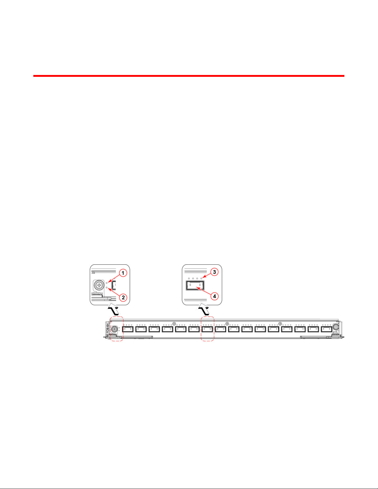
The following figure identifies the FC16-64 blade ports and LED indicators:
FIGURE 1 FC16-64 port blade
1. Blade status LED
2. Blade power LED
3. Port status LED for FC port 36
4. QSFP port 9; FC ports 36-39 (right to left)
The ports are numbered from 0 through 63 from right to left in the Brocade DCX 8510-4, and bottom to
top in the Brocade DCX 8510-8. The trunking port groups are 0-7, 8-15, 16-23, 24-31, 32-39, 40-47,
48-55, and 56-63.
FC16-64 Port Blade QuickStart Guide
53-1003197-01
3
Page 6
QSFP transceiver
QSFP transceiver
The FC16-64 port blade supports only Quad-SFP (QSFP) ports where a single MTP connector
supports up to four channels or ports. Thus, QSFP allows for simplified cable management and, at the
same time, supports high density SAN solutions. The QSFP transceivers differ from standard SFP+ or
mSFP transceivers. Cables with MTP/MPO connectors are required to use the QSFP transceivers.
The cables can be identified by the special connector at the QSFP end and the cables are of different
diameter (2.5×6.4 mm)than the standard LC-LC cables.
CAUTION
DO not use the standard SFP+ or mSFP optical transceivers with the FC16-64 port blade. They
do not fit correctly and can cause damage to the ports, cage connectors, and transceivers. Do
not force standard LC or mSFP connectors into the QSFP transceivers. This could result in
damage to both the connector and the cable.
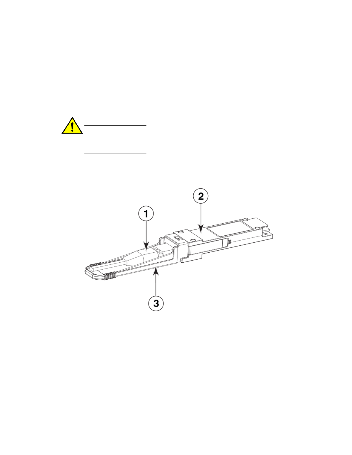
The following figure shows the QSFP transceiver and the connector.
FIGURE 2 QSFP transceiver
1. QSFP MTP connector
2. QSFP transceiver
3. Transceiver pull tab
Qualified transceivers for the FC16-64 port blade and the core blades
The following table shows the qualified transceivers for the FC16-64 port blade and the core blades.
4 FC16-64 Port Blade QuickStart Guide
53-1003197-01
Page 7

Cable types supported on the FC16-64 port blade
Qualified transceivers for FC16-64 port blade and the core bladesTABLE 1
Brocade part
number
57-1000294-01
57-1000267-01
57-0000090-01
Part type Cable length Port speeds Supported blades
QSFP transceiver 100 m OM4 Auto-negotiable 4-, 8-,
and 16-Gbps
QSFP transceiver 100 m OM4 Only fixed 16-Gbps
QSFP transceiver 50 m OM3
NOTE
The QSFP transceivers supported on FC16-64 port blade are not interchangeable with QSFP
transceivers supported on the core blades.
Cable types supported on the FC16-64 port blade
The FC16-64 port blade supports simplified cable management using QSFP cables. Each QSFP cable
has four links internally that run at 16-Gbps speed and the cables come in specific predetermined fixed
lengths.
The FC16-64 port blade supports the following types of cables:
FC16-64
CR16-4/8
FIGURE 3 QSFP to QSFP standard cables
1. QSFP MTP connector
FIGURE 4 QSFP-SFP/LC Break-out/Split-out cables
1. QSFP MTP connector
2. SFP+ LC connectors
FC16-64 Port Blade QuickStart Guide 5
53-1003197-01
Page 8

FC16-64 Overview
With the support for breakout cables, each port can be in a different mode. Inside the single physical
QSFP port, individual ports can be configured as an E_Port, F_Port or EX_Port. Also, each internal
port inside a single physical QSFP can be part of different Logical Switches.
With the support for breakout cables, trunking can be enabled on ports in a QSFP port group, with
ports connected through breakout cables at the other end.
6 FC16-64 Port Blade QuickStart Guide
53-1003197-01
Page 9

Installing the FC16-64
● Before you begin............................................................................................................... 7
● ESD precautions............................................................................................................... 7
● Time required for installation tasks................................................................................... 7
● Items required................................................................................................................... 7
● Installing the blade in the chassis..................................................................................... 8
● Attaching cables to the blade............................................................................................ 9
● Bundling and routing cables............................................................................................10
● Attaching cables to the patch panels.............................................................................. 12
Before you begin
Be sure to establish a naming or numbering scheme before you begin attaching cables. Each cable
should have a unique designation and should be labeled accordingly. You should also record this
information separately for future reference and troubleshooting. If you are using break-out cables,
remember to label appropriately that you know which ends are being connected. Refer to the serial
numbers on the break-out side of the cables for proper identification of individual channels or ports.
ESD precautions
The Brocade DCX Backbone series contains ESD-sensitive field-replaceable units (FRUs). When
working with any FRU, use correct electrostatic discharge (ESD) procedures.
• Wear a wrist grounding strap connected to chassis ground or a bench ground.
• Store ESD-sensitive components in antistatic packaging.
Time required for installation tasks
• Installing a single FC16-64 in a chassis should take less than five minutes.
• Refer to the documentation accompanying any patch panels for the approximate time to install and
pre-cable the panels.
• Attaching cables, bundling and routing them, and attaching the cables to the patch panel for one
FC16-64 should take approximately 40 minutes, depending on experience and the ability to work
with cable connections.
Items required
You should have the following items before you start installing FC16-64 port blade:
FC16-64 Port Blade QuickStart Guide
53-1003197-01
7
Page 10

Installing the blade in the chassis
• FC16-64 port blades (as many as ordered)
• Sufficient number of QSFP transceivers to fill the FC16-64 blades.
• Velcro® strips
• QSFP to QSFP cables (if necessary, to be used as inter-switch links (ISLs) or MTP patch panels)
• QSFP-LC patch cables (if necessary, to be used with LC patch panels)
• Phillips screwdriver
Installing the blade in the chassis
Complete the following steps to install the port blade in the chassis.
1. Ensure that all packing material have been removed from the blade.
2. Orient the blade so that the ports are at the front of the chassis and the flat side of the blade is at
the bottom when installing in the DCX 8510-4. Orient the blade with the flat side on the left when
installing in the DCX 8510-8
For an example of how a blade needs to be oriented in 8510-4 chassis, refer to the following
illustration.
FIGURE 5 Insertion of the FC16-64 port blade in DCX 8510-4
8 FC16-64 Port Blade QuickStart Guide
53-1003197-01
Page 11

Attaching cables to the blade
For an example of how a blade needs to be oriented in 8510-8 chassis, refer to the following
illustration.
FIGURE 6 Insertion of the FC16-64 port blade in DCX 8510-8
3. Adjust the ejectors to the open position by rotating them toward the center of the blade, align the
flat side of the blade inside the upper and lower rail guides in the slot, and slide the blade into the
slot until it is firmly seated.
4. Close the ejectors by rotating them away from the center of the blade.
5. Tighten the thumbscrews using the Phillips screwdriver.
Attaching cables to the blade
To attach the QSFP connector end of the QSFP cable to the FC16-64 blade, complete the following
steps.
FC16-64 Port Blade QuickStart Guide 9
53-1003197-01
Page 12

Bundling and routing cables
1. Remove the protective caps on the QSFP transceiver and the QSFP connector on the cable.
2. If the transceiver was not pre-installed, grasp the bail of the QSFP transceiver and push the
3. Grasp the QSFP connector end of the cable by the rubber housing and push it into the transceiver
4. Repeat steps 1 to 3 to attach all the cables to the blade.
transceiver into the port until it is firmly seated and the latching mechanism clicks. The transceiver
is keyed to fit into the port with the correct orientation. If a transceiver does not slide in easily,
ensure that it is correctly oriented. The Status LED blinks amber upon initial installation, and then
displays a steady amber.
FIGURE 7 Insertion of MTP/MPO connector to the QSFP transceiver
until it is firmly seated. The cable housing is keyed to fit into the transceiver with correct
orientation. The status LED displays steady amber until both ends of the cable are inserted and
the link is established. When the link is fully established, the LED displays steady green.
Bundling and routing cables
When you have cabled an entire FC16-64 port blade, complete the following steps to organize and
route the optical cables.
NOTE
Do not use plastic zip ties or metal tie wraps as these can be overtightened and damage the optical
cables.
1. Bundle the cables together with Velcro strips.
2. Route the bundle of cables through the cable management comb and dress the cables to the side
of the rack.
10 FC16-64 Port Blade QuickStart Guide
53-1003197-01
Page 13

Installing the FC16-64
For the DCX 8510-8, the cable management combs are mounted to the bottom of the chassis. You
need to route the cables towards the bottom and then bundle them together for each FC16-64 port
blade.
FIGURE 8 Cable routing in DCX 8510-8
For the DCX 8510-4, the cable management fingers are mounted to the sides of the chassis,
making the task of bundling and routing the cables in two directions. You can group the cables on
FC16-64 Port Blade QuickStart Guide 11
53-1003197-01
Page 14

Attaching cables to the patch panels
the left of a FC16-64 port blade to the left cable management finger, and those in the right to the
right cable management finger.
FIGURE 9 Cable routing in DCX 8510-4
Attaching cables to the patch panels
You can use three types of patch panels to connect FC16-64 port blades to other devices.
• MTP to MTP patch panels (requires MTP-MTP QSFP cables)
• MTP to LC patch panels (requires MTP-MTP QSFP cables and LC-LC cables)
• LC to LC patch panels (requires MTP-LC QSFP breakout cables and LC-LC cables
The following section describes the procedure for LC-LC patch panel with MTP-LC breakout/split
cables connected to the FC16-64 port blade:
To connect the cables to the patch panels, complete the following steps. You should have one 72-port
LC-LC patch panel for each FC16-64 port blade. Eight ports in each patch panel will not be used.
Remember to keep all the ports properly documented and labeled. Because the patch panel tray
slides out for access, be sure to leave enough slack in the cabling to accommodate this movement.
12 FC16-64 Port Blade QuickStart Guide
53-1003197-01
Page 15

Installing the FC16-64
1. Install the patch panel in the rack. See the directions accompanying the patch panel for detailed
mounting instructions. Leave a one rack unit gap between the bottom of a DCX 8510-8 chassis and
the first patch panel to allow for bending of the optical cables after they pass through the cable
management comb. If you mount the patch panels above the chassis, leave a one rack unit gap
below a chassis for bending the cables after they pass through the cable management comb.
2. Route the patch cables from the FC16-64 blades into the front of each patch panel shelf. Each
patch panel has three shelves. When you slide the tray out from the front of the rack, the top two
shelves can rotate upward to facilitate access.
3. Remove the protective caps on the ends of the MTP/LC connectors of the patch cables.
4. Insert the connector from the FC16-64 port blade into the front receptacles of the patch panel until
the latching mechanism clicks. Repeat until all cables have been inserted into the patch panel.
5. Route the cables from other devices through the rear of the patch panel and then slide the panel
out to the front. Be sure these cables have been labeled and bundled properly.
6. Insert the connector from the other devices into the back side of the patch panel. Repeat until all
cables have been inserted into the back of the patch panel.
7. Slide the patch panel back into the rack.
FC16-64 Port Blade QuickStart Guide 13
53-1003197-01
Page 16

Attaching cables to the patch panels
14 FC16-64 Port Blade QuickStart Guide
53-1003197-01
Page 17

Additional documentation
For more information, refer to the following documents:
• DCX 8510-8 Backbone Hardware Reference Manual
• DCX 8510-8 Backbone QuickStart Guide
• DCX 8510-4 Backbone Hardware Reference Manual
• DCX 8510-4 Backbone QuickStart Guide
FC16-64 Port Blade QuickStart Guide 15
53-1003197-01
Page 18

Additional documentation
16 FC16-64 Port Blade QuickStart Guide
53-1003197-01
 Loading...