


Broan S80UE, S80U, S110UE, S50U, S110U User Manual
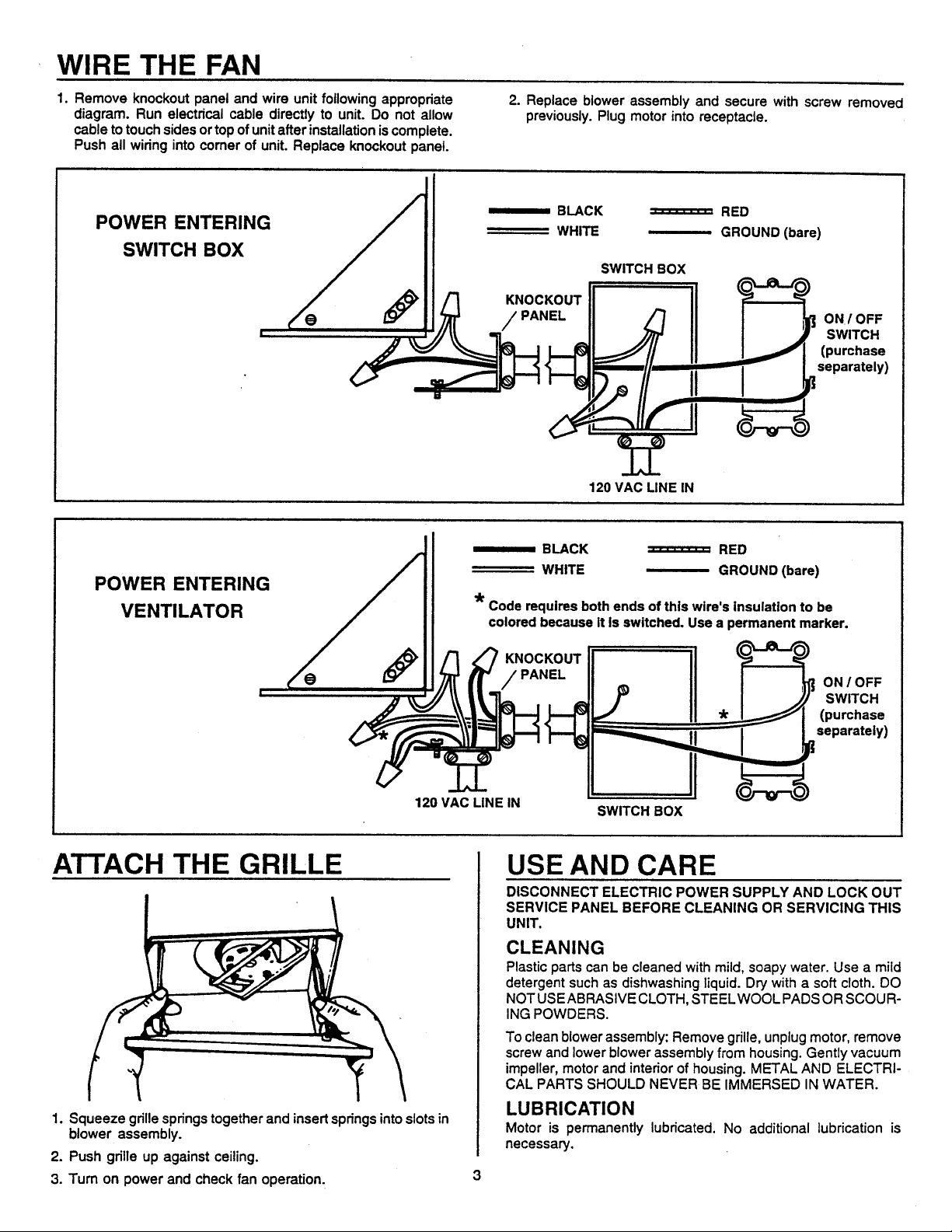
MODELS
POWER
CABLE
SUSPENDED CEILING
MATERIAL
4" ROUND DUCT
HOUSING
S50U, S80U, S80UE,
S110U & S110UE
SOLITAIRE ULTRA-SILENT® FAN
READ AND SAVE THESE INSTRUCTIONS
WARNING
TO REDUCE THE RISK OF FIRE, ELECTRIC SHOCK, OR INJURY
TO PERSONS, OBSERVE THE FOLLOWING:
1. Use this unit only in the manner intended by the manufacturer. If
you have questions, contact the manufacturer at the address or
telephone number listed in the warranty.
2. Before servicing or cleaning unit, switch power off at service panel
and lock the service disconnecting means to prevent power from
being switched on accidentally. When the service disconnecting
means cannot be locked, securely fasten a prominent warning
device, such as a tag, to the service panel.
3. Installation work and electrical wiring must be done by a qualified
person(s) in accordance with all applicable codes and standards,
including fire-rated construction codes and standards.
4. Sufficient air is needed for proper combustion and exhausting of
gases through the flue (chimney) of fuel burning equipment to
prevent backdrafting. Follow the heating equipment manufacturer’s
guideline and safety standards such as those published by the
National Fire Protection Association (NFPA), and the American
Society for Heating, Refrigeration and Air Conditioning Engineers
(ASHRAE), and the local code authorities.
5. When cutting or drilling into wall or ceiling, do not damage electrical
wiring and other hidden utilities.
TYPICAL INSTALLATION
CEILING
JOIST
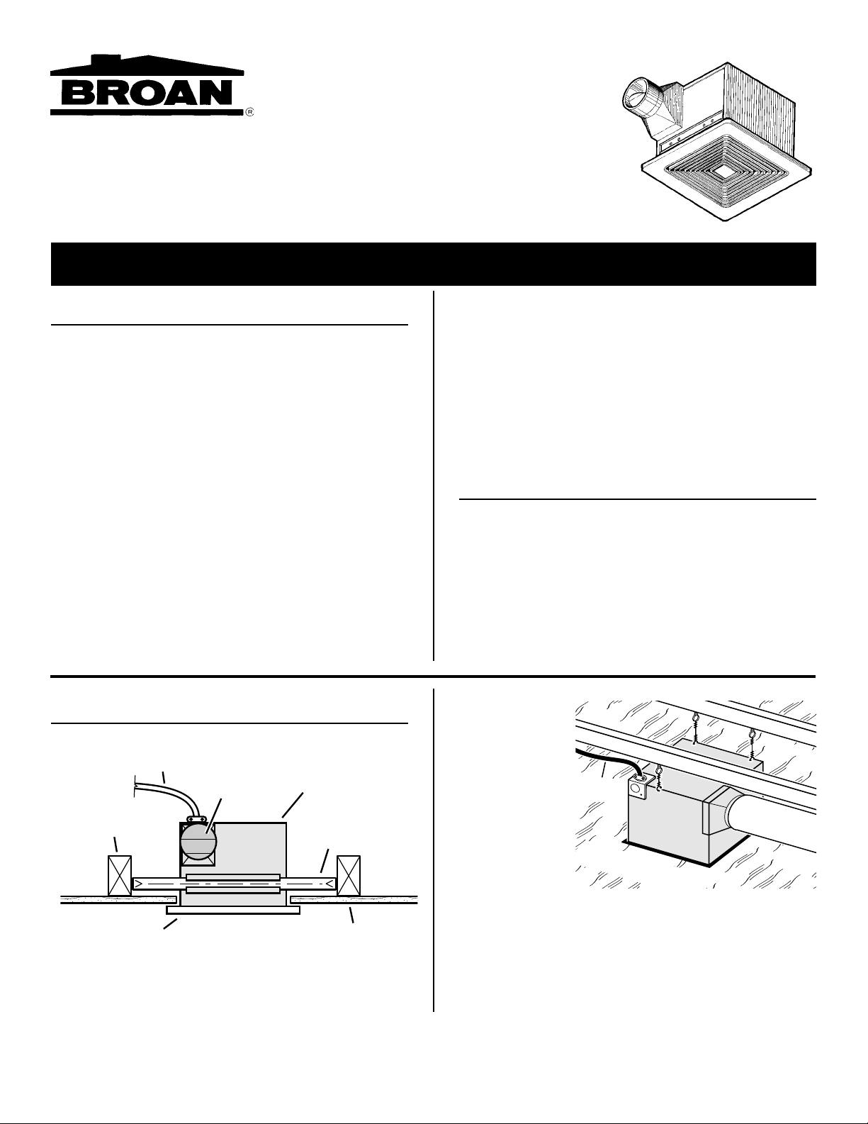
This unit can be installed anywhere between joists using mounting
brackets provided.
INSTALLER: LEAVE THIS MANUAL WITH THE HOMEOWNER.
HOMEOWNER: USE AND CARE INSTRUCTIONS ON PAGE 3.
POWER
CABLE
GRILLE FINISHED CEILING
4" ROUND
DAMPER/DUCT
CONNECTOR
HOUSING
MOUNTING
BRACKET
6. Ducted fans must always be vented to the outdoors.
7. If this unit is to be installed over a tub or shower, it must be marked
as appropriate for the application and be connected to a GFCI
(Ground Fault Circuit Interrupter) - protected branch circuit.
8. Never place a switch where it can be reached from a tub or shower.
9. This unit may be used over a tub or shower enclosure when
installed in a GFCI protected branch circuit. (Ceiling Installation
only)
10. This unit must be grounded.
CAUTION
1. For general ventilating use only. Do not use to exhaust hazardous
or explosive materials and vapors.
2. To avoid motor bearing damage and noisy and/or unbalanced
impellers, keep drywall spray, construction dust, etc. off power
unit.
3. Please read specification label on product for further information
and requirements
The unit can be
installed in a
suspended ceiling
using wire as
shown.
The unit will operate
most quietly when
located where the
shortest possible
duct run and
minimum number of
elbows will be
needed.
Plan to supply the
unit with proper line voltage and appropriate power cable.
Follow these basic steps when installing this unit:
• Nail housing to joists.
• Attach ductwork.
• Connect power cable.
• Install blower assembly.
• Fasten grille to housing.
.

PREPARE THE FAN
1. Remove the screw holding the blower assembly in place. Lift
assembly from housing.
INSTALL THE FAN (CONT'D)
Å
Å
1½" FOR
½" DRYWALL
2. Remove housing temporarily, and pound nails partially into
joists at all four marked locations.
2. Slide adjustable mounting brackets into bracket channels on
housing. NOTE: Housing may be mounted directly to joist
using keyholes provided.
INSTALL THE FAN
1. Position housing between joists and extend mounting brackets. Position brackets such that bottom edge of housing will be
flush with finished ceiling. Mark the top of keyhole on all four
mounting brackets.
3. Hang housing from nails. Use measuring guides on corners of
housing to check if unit will be flush with finished ceiling. Pound
nails tight. For wide joist centers: A #8 x 3/8 self-tapping screw
can be used to join extended brackets together and create a
rigid mount. To ensure a noise-free mount, crimp the bracket
channels tightly around mounting brackets.
4. Snap the damper/duct connector onto housing. Make sure that
tabs on the duct connector lock in housing slots and that gravity
closes damper.
5. Install 4” round duct and extend duct to outside through a roof
or wall cap. Check damper to make sure that it opens freely.
Tape all duct connections to make them secure and air tight.
2
 Loading...