


Bradford White RG130T6N, RG230T6N, RG230S6N, RG140T6N, RG240T6N User Manual
...
Flammable Vapor Ignition Resistant
Water Heaters
SERVICE
MANUAL
Troubleshooting Guide and Instructions for Service
(To be performed ONLY by qualified service providers)
Models Covered
by This Manual:
RG130T*(N,X) RG230S*(N,X)
RG140T*(N,X) RG230T*(N,X)
RG150T(N,X) RG240S*(N,X)
RG140S*(N,X) RG240T*(N,X)
RG150L*(N,X) RG250H*(N,X)
RG150S*(N,X) RG250L*(N,X)
LG255H*(N.X) RG250S*(N,X)
LG275H*(N,X) RG250T*(N,X)
LG250H65*(N,X) RG250H*(N,X)
RG2100H*(N,X) RG255H*(N,X)
RG275H*(N,X)
(*) Denotes Warranty Years
Manual 238-51542-00C REV 08/19 |
|
|
|
|
|
|
|
|
|
|
|
|
|
|
|
|
|
|
|
|
|
|
|
|
|
|
|
|
|
|
|
|
|
|
|
Save this manual for future reference |
|||||

The Bradford White
DEFENDER
Safety System®
Flammable Vapor Ignition Resistant Water Heaters
Table of Contents
Page |
Service |
Procedure |
|
Introduction………………………………………………………………………………...4 |
--- |
Troubleshooting Charts……………………………………………………………..…...6 |
--- |
Inner Door Gasket Removal, Inspection, and Replacement………………………..12 |
RG-I |
Thermocouple/Thermopile Testing and Replacement………………………….…..15 |
RG-II |
Pilot Assembly Inspection Cleaning and Replacement……………………………..18 |
RG-III |
Piezo Igniter, Electrode Testing and Replacement……………………………..…..19 |
RG-IV |
White Rodgers Mechanical Gas Valve Testing and Replacement…………….…..20 |
RG-V |
Electronic Gas Control Testing, Disassembly, and Replacement…………… …..25 |
RG-VI |
Burner Operation Inspection, Adjustment, Cleaning, and Replacement…………..35 |
RG-VII |
Resettable Thermal Switch Testing and Replacement……………………….. .…..37 |
RG-VIII |
ScreenLok® Flame Arrestor Cleaning………………………………………………..39 |
RG-IX |
Diptube and Anode Inspection and Replacement…………………………………..40 |
RG-X |
Parts Diagram……………………………………………………………………….…..42 |
--- |
Notes………..………………………………………………………………………… ...43 |
--- |
2
2
WARNING: If the information in these instructions is not followed exactly, a fire or explosion may result in property damage, personal injury, or death.
For Your Safety
Do not store or use gasoline or other flammable, combustible, or corrosive vapors and liquids in the vicinity of this or any other appliance.
–WHAT TO DO IF YOU SMELL GAS
x Do not try to light any appliance.
x Do not touch any electrical switch; do not use any phone in your building.
x Immediately call your gas supplier from a neighborʼs phone. Follow the gas supplierʼs instructions.
x If you cannot reach your gas supplier, call the fire department.
–Installation and service must be performed by a qualified installer, service agency, or the gas supplier.


 DANGER
DO NOT store or use gasoline or other flammable, combustible, or corrosive vapors and liquids in the vicinity of this or any other appliance.
IMPORTANT
Before proceeding, please inspect the water heater and its components for possible damage. DO NOT install any water heater with damaged components. If damage is evident then please contact the supplier where the water heater was purchased or the manufacturer listed on the rating plate for replacement parts.


 WARNING
Water heaters are heat producing appliances. To avoid damage or injury, do not store materials against the water heater or vent-air intake system. Use proper care to avoid unnecessary contact
(especially by children) with the water heater and vent-air intake components. UNDER NO
CIRCUMSTANCES SHOULD FLAMMABLE MATERIALS, SUCH AS GASOLINE OR PAINT THINNER BE USED OR STORED IN THE VICINITY OF THIS WATER HEATER, VENT-AIR INTAKE SYSTEM OR IN ANY LOCATION FROM WHICH FUMES COULD REACH THE WATER HEATER OR VENT-AIR INTAKE SYSTEM.


 WARNING
Hydrogen gas can be produced in an operating water heater that has not had water drawn from the tank for a long period of time (generally two weeks or more). HYDROGEN GAS IS EXTREMELY FLAMMABLE. To prevent the possibility of injury under these conditions, we recommend the hot water faucet to be open for several minutes at the kitchen sink before you use any electrical appliance which is connected to the hot water system. If hydrogen is present, there will be an unusual sound such as air escaping through the pipes as hot water begins to flow. DO NOT smoke or have open flame near the faucet at the time it is open.


 WARNING
DO NOT ATTEMPT TO LIGHT ANY GAS APPLIANCE IF YOU ARE NOT CERTAIN OF THE FOLLOWING:
xLiquefied petroleum gases/propane gas and natural gas have an odorant added by the gas supplier that aids in the detection of the gas.
xMost people recognize this odor as a “sulfur” or “rotten egg” smell.
xOther conditions, such as “odorant fade” can cause the odorant to diminish in intensity, or “fade”, and not be as readily detectable.
xIf you have a diminished sense of smell or are in any way unsure of the presence of gas, immediately contact your gas supplier from a neighborʼs telephone.
Gas detectors are available. Contact your gas supplier, or plumbing professional, for more information.


 WARNING
FAILURE TO INSTALL AND MAINTAIN A NEW, LISTED 3/4” X 3/4” TEMPERATURE AND PRESSURE RELIEF VALVE WILL RELEASE THE MANUFACTURER FROM ANY CLAIM THAT MIGHT RESULT FROM EXCESSIVE TEMPERATURE AND PRESSURES.


 CAUTION
If sweat fittings are to be used DO NOT apply heat to the nipples on top of the water heater. Sweat the tubing to the adapter before fitting the adapter to the water connections. It is imperative that heat is not applied to the nipples containing a plastic liner.
3
3

INTRODUCTION
The Bradford White DEFENDER Safety System®
The Bradford White DEFENDER Safety System® was designed to resist the ignition of flammable vapors that can occur outside of the water heater. Use and installation are nearly identical to previous versions of atmospherically fired and vented water heaters. A number of exclusive design features are incorporated in the system that will require additional knowledge on the part of the qualified service provider. The following information will instruct service professionals on the function, proper diagnosis and repair of water heaters employing the Bradford White DEFENDER Safety System.
How the Safety System Works
During normal operation, air for combustion is drawn into the water heater through the opening in the jacket. This air travels down and around the combustion chamber and enters through holes in the very bottom of the corrosion-resistant combustion chamber. The air then travels up through the oriented flame arrestor plate louvers, where the velocity of the air is increased, and its direction altered. The air then mixes in a normal manner with the supplied gas and is efficiently combusted, producing very low NOx emissions.
In the case where trace amounts of flammable vapors are present in the air flowing into the combustion chamber, the vapors are harmlessly ignited by the burner/pilot flame. If flammable vapors are in sufficient quantity to prevent normal combustion, the burner/pilot flame is shut down.
Should the flammable vapors continue to the burner, the flame arrestor plate prevents the flames from traveling backwards and igniting vapors outside of the combustion chamber. The calibrated, multipurpose thermal switch recognizes this and shuts down the pilot and main burner. This switch also deactivates the burner and pilot in the unlikely event of restricted airflow caused by severe lint, dust, or oil accumulation on the arrestor plate.
4
4
It is intended for this manual to be used by qualified service personnel for the primary purpose of troubleshooting and repair of the Bradford White DV Series water heaters.
The Honeywell Icon Gas Control will display status codes in the event of abnormal operation. Status codes are listed in the troubleshooting charts found in this service manual. The troubleshooting charts will also indicate the probable cause for the status code and direct the service professional to a service procedure to properly diagnose the abnormal operation.
In some difficult to diagnose conditions, it may be necessary to isolate the heater from the vent system to determine the problem.
Contact the Bradford White technical support group immediately if diagnosis cannot be made using the methods described in this service manual.
Tools Required for Service
Manometer: A liquid “U” tube type or a digital (magnahelic) type can be used. This device is used to measure gas and/or air pressure and vacuum.
Multi-Meter: A digital type is strongly recommended. This device is used to measure electrical values. The meter you select must have the capability to measure volts AC, volts DC, amps, micro-amps, and ohms.
Electronic Probes: In some cases, standard multi-meter probes will damage or simply not be effective to obtain certain voltage and ohm readings. It will be necessary to have special electronic “pin” type multi-meter probes. These probes are available at most electronic wholesale outlets.
Thermometer: Used to measure water temperature. An accurate thermometer is recommended.
Water Pressure Gage: Used to measure water supply pressure. Also used to determine tank pressure by adapting to the drain valve of the heater.
Various Hand Tools: Pipe wrench, channel locks, open end wrenches (3/8”, 7/16”, 1/2”), 12” crescent wrench, allen wrench set, screw drivers (common & Phillips), 1/4” nut driver, pliers (common & needle nose), socket set, side cutters, wire cutters, wire strippers, wire crimpers, torpedo level, small shop vacuum, step ladder, flashlight, and 5-gallon pail.
5
5

White Rodgers Mechanical Gas Control Troubleshooting Chart
Flammable Vapor Ignition Resistant Water Heaters
|
|
|
|
|
Symptom |
Probable Cause |
Corrective Action |
Service |
|
Procedure |
||||
|
|
|
||
|
1.No incoming gas or too low |
1.Turn on gas supply and/or check |
|
|
|
gas pressure. |
1.See Service |
||
|
2.Gas control knob set to |
line pressure. |
||
|
wrong position. |
2.Review lighting instruction. Set gas |
Procedure RG-V |
|
|
3.Gas control knob not being |
control knob to correct position. |
2.See Service |
|
Pilot will not light |
fully depressed when |
3.Review lighting instruction. Fully |
Procedure RG-III |
|
attempting to light pilot. |
depress gas control knob. |
3.See Service |
||
|
||||
|
4.Pilot orifice or pilot tube is |
4.Clean, repair or replace. |
Procedure RG-III |
|
|
obstructed or kinked. |
5.Verify correct electrode position. |
4.See Service |
|
|
5.Pilot electrode not sparking to |
Replace pilot assembly. |
Procedure RG-IV |
|
|
pilot. |
6.Replace piezo igniter. |
|
|
|
6.Piezo igniter not functioning. |
|
|
|
|
|
1.Check connection at combination |
|
|
|
1.Poor thermocouple |
thermostat/gas valve. Proper |
|
|
|
tightness should be finger tight |
|
||
|
connection at combination |
|
||
|
+ a 1/4 turn. |
|
||
|
thermostat/gas valve. |
|
||
|
2.Inspect thermocouple to ensure |
|
||
|
2.Thermocouple not fully |
|
||
|
that it is fully engaged into pilot |
|
||
|
engaged in pilot assembly |
|
||
|
bracket. |
|
||
|
bracket. |
|
||
|
3.Clean pilot orifice and verify pilot |
|
||
|
3.Pilot flame is not fully |
1.See Service |
||
|
tube is clear; check gas supply |
|||
|
enveloping the thermocouple |
|||
|
and line pressure. |
Procedure RG-II |
||
Pilot will not stay lit |
bulb. |
|||
4.Check thermocouple and replace |
2.See Service |
|||
when button is |
4.Weak or defective |
|||
if necessary. |
Procedure RG-V |
|||
released |
thermocouple. |
|||
5.Check ECO continuity and replace |
3.See Service |
|||
|
5.Open ECO in |
|||
|
combination thermostat/gas valve |
Procedure RG-V |
||
|
combination thermostat/ |
|||
|
if necessary. |
|
||
|
gas valve. |
|
||
|
6.Check magnet operation and |
|
||
|
6.Defective magnet in |
|
||
|
replace combination |
|
||
|
combination thermostat/gas |
|
||
|
thermostat/gas valve if necessary. |
|
||
|
valve. |
|
||
|
7.Determine cause of switch |
|
||
|
7.Resettable thermal switch |
|
||
|
activation. To reset, depress |
|
||
|
has opened. |
|
||
|
button on resettable thermal |
|
||
|
|
switch located on inner door. |
|
|
|
1.Combination thermostat/gas |
1.Adjust temperature dial on |
|
|
|
combination thermostat/gas |
|
||
|
valve set too low for desired |
|
||
|
valve. |
1.See Installation |
||
|
water temperature. |
|||
|
2.Check temperature dial |
|||
|
2.Combination |
and Operation |
||
Pilot will light but |
setting on combination |
|||
thermostat/gas valve |
Manual. |
|||
thermostat/gas valve. |
||||
the main burner |
temperature is satisfied. |
2.See Service |
||
3.Check gas supply and line |
||||
will not come on |
3.Insufficient gas supply or |
Procedure RG-V |
||
pressure. |
||||
|
low gas pressure. |
3.See Service |
||
|
4.Check combination |
|||
|
4.Combination thermostat/gas |
Procedure RG-V |
||
|
thermostat/gas valve for |
|||
|
valve has wide differential or |
|
||
|
proper operation, replace if |
|
||
|
is out of calibration. |
|
||
|
necessary. |
|
||
|
|
|
6
6

White Rodgers Mechanical Gas Control Troubleshooting Chart
Flammable Vapor Ignition Resistant Water Heaters
|
|
|
|
|
|
Symptom |
|
Probable Cause |
|
Corrective Action |
Service |
|
|
Procedure |
|||
|
|
|
|
|
|
|
|
|
1. |
Verify adequate combustion air |
|
|
|
|
|
is available to the unit. Check |
|
|
1. |
Insufficient combustion air |
|
and clear jacket slot openings of |
|
Pilot goes out |
|
any dirt, dust, restrictions or |
1. See Service |
||
|
supply. |
|
other obstructions. Inspect flame |
||
periodically (after |
2. Incorrect or clogged vent |
|
arrestor plate and clean with stiff |
Procedure RG- |
|
heating cycles, |
|
system/vent terminal, or |
|
bristled brush and compressed |
VIII |
once a day, once |
|
incorrect location. |
|
air to remove any debris |
2. See Service |
a week etc.) |
3. Inconsistent gas supply or |
2. |
accumulation. |
Procedure RG-V |
|
|
|
gas pressure. |
Check venting for proper sizing |
|
|
|
|
|
3. |
and proper operation. |
|
|
|
|
Check gas supply and line |
|
|
|
|
|
|
pressure. |
|
|
1. |
Combination thermostat/gas |
1. |
Check dial on combination |
|
|
|
valve set too low for desired |
2. |
thermostat/gas valve. |
|
|
2. |
water temperature. |
Extremely cold water going into |
|
|
|
Cold inlet water temperature |
|
the heater will decrease the |
|
|
|
3. |
is very cold. |
|
amount of hot water produced. It |
1. See Service |
Not enough hot |
High demand periods. |
|
may be necessary to temper |
||
4. Incorrectly sized water |
3. |
incoming water supply. |
Procedure RG-V |
||
water |
|
heater for application. |
Adjust high demand usage. |
2. See Service |
|
|
5. Combination thermostat/gas |
4. |
Contact plumbing professional. |
Procedure RG-IX |
|
|
|
valve is out of calibration/not |
5. |
Check combination |
|
|
|
functioning. |
|
thermostat/gas valve for proper |
|
|
6. Out of spec dip tube is |
6. |
operation, replace if necessary. |
|
|
|
|
diluting hot water with cold |
Inspect dip tube and replace if |
|
|
|
|
water. |
|
necessary. |
|
7
7
White Rodgers ElectronicGas Control Troubleshooting Chart
FlammableVaporIgnitionResistantWaterHeaters
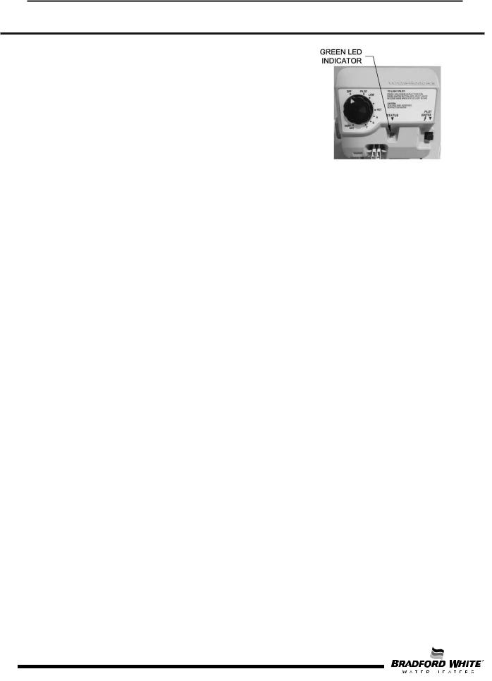
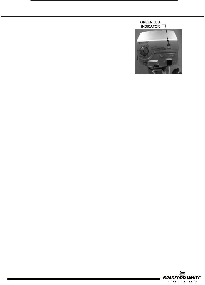
Observe green LED indicator on gas control. Status flash codes are displayed with a three second pause before repeating. Check and repair the system as noted in the troubleshooting table below.
|
|
|
|
|
|
LED Status |
Control Status |
Probable Cause |
|
|
None (LED not on |
Indicates control is off. Main |
Gas valve is functioning normally. Gas valve is |
|
|
or flashing) |
and pilot burner are off. |
not powered. Light pilot. |
|
|
|
|
|
|
|
One flash every |
Not an error. Indicates pilot is |
Gas valve is powered and waiting for the set |
|
|
point knob to be turned to a water temperature |
|
||
|
four seconds |
lit and main burner is off. |
setting. If the set point knob is at desired setting, |
|
|
|
|
the thermostat is satisfied. |
|
|
|
|
|
|
|
One flash every |
Not an error. Indicates main |
Thermostat is calling for heat. Water heater |
|
|
valve is open and main |
|
||
|
second |
operating normally and is in heat cycle. |
|
|
|
burner is lit. |
|
||
|
|
|
|
|
|
|
|
|
|
|
Solid ON |
Not an error. Indicates that |
Set point knob was recently turned to “OFF” |
|
|
the control is in shutdown |
position. Wait until LED goes out before |
|
|
|
|
mode. |
attempting to relight. |
|
|
|
|
|
|
|
Two flashes and |
Low thermopile voltage; main |
Loose thermopile connections or weak pilot |
|
|
three second |
|
||
|
burner not lit. |
flame. |
|
|
|
pause |
|
||
|
|
|
|
|
|
|
|
|
|
|
Four flashes and |
|
Excessive temperatures may have been |
|
|
Temperature cut-out limit |
reached. Shut off the control and reduce the |
|
|
|
three second |
|
||
|
reached causing shutdown. |
water temperature. Thoroughly verify control |
|
|
|
pause |
|
||
|
|
operation, replace if exceeding setpoint. |
|
|
|
|
|
|
|
|
|
|
|
|
|
Five flashes and |
Electronics, sensor, or gas |
Control may be wet or damaged. Verify all |
|
|
three second |
connections are tight; if problem persists replace |
|
|
|
valve fault detected. |
|
||
|
pause |
the control. |
|
|
|
|
|
||
|
|
|
|
|
|
|
|
|
|
8
8
Honeywell V1Gas Control Troubleshooting Chart
FlammableVaporIgnitionResistantWaterHeaters
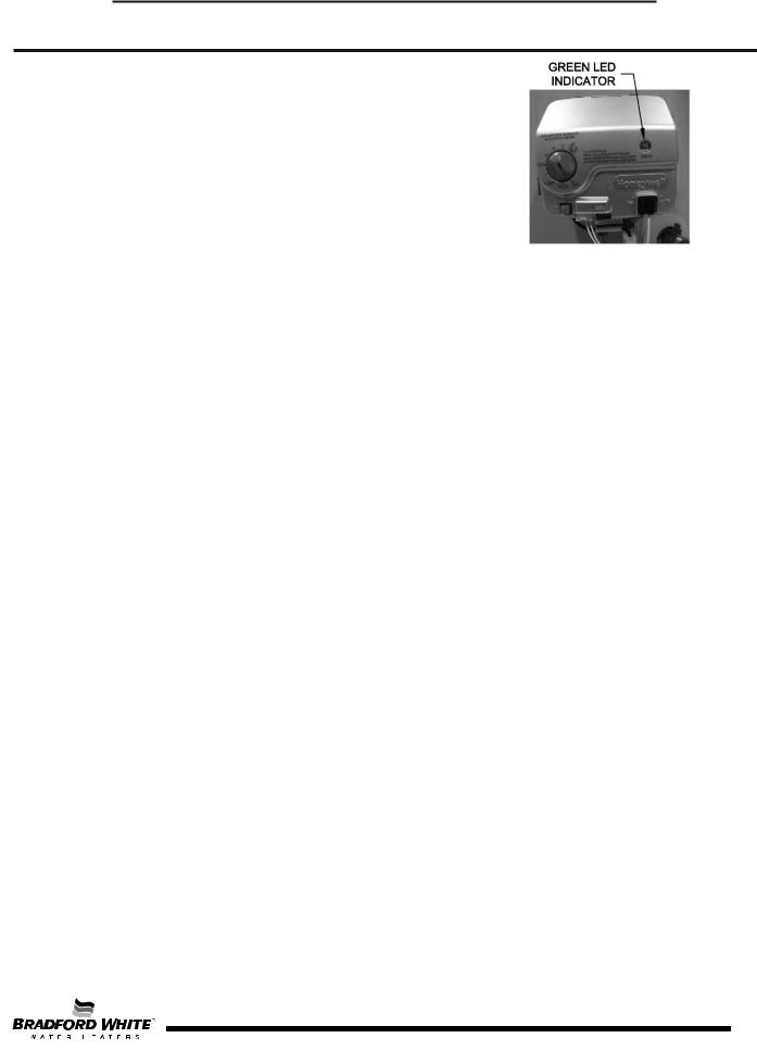
Observe green LED indicator on gas control. Status flash codes are displayed with a three second pause before repeating. Check and repair the system as noted in the troubleshooting table below.
|
|
|
|
|
|
LED Status |
Control Status |
|
Probable Cause |
Service Procedure |
|
None (LED not |
|
Gas control is not |
If the pilot will not stay lit |
||
Pilot assembly is not lit. |
replace pilot assembly. If |
||||
on or flashing) |
powered. Light pilot. |
problem persists replace |
|||
|
|
|
|
gas control. |
|
|
1. If setpoint knob is in “PILOT” |
1. |
Gas control is |
|
|
|
position then pilot flame is |
|
powered and waiting |
|
|
One flash and |
detected. Turn setpoint knob |
|
for setpoint knob to |
|
|
to desired setting. |
|
be turned to a water |
Normal operation. |
||
three second |
|
||||
2. If the setpoint knob is |
|
temperature setting. |
|||
pause |
|
|
|||
already at the desired |
2. |
Water heater is |
|
||
|
|
||||
|
setting, the water heater is |
|
satisfied and |
|
|
|
satisfied. |
|
operating normally. |
|
|
LED on |
Setpoint knob has been recently |
Setpoint knob was |
LED will go out and the |
||
turned to the “OFF” position. Wait |
|||||
continuously |
until LED goes out before |
turned to “OFF” |
control will function |
||
(solid) |
position. |
normally once the pilot is lit. |
|||
attempting to relight. |
|||||
|
|
|
|
||
Two flashes |
Weak pilot signal detected. |
1. |
Thermopile failure. |
1. See Service Procedure IV |
|
2. |
Unstable pilot. |
||||
and three |
System will reset when pilot |
2. See Service Procedure II |
|||
3. |
Pilot tube blocked or |
||||
second pause |
flame is sufficient. |
3. See Service Procedure II |
|||
|
restricted. |
||||
|
|
|
|
||
|
|
|
|
|
|
Three flashes |
Insufficient water heating. |
1. |
Thermal sensor out |
|
|
and three |
|
of calibration. |
Replace gas control. |
||
System will reset. |
|
||||
second pause |
2. |
Faulty gas control. |
|
||
|
|
||||
|
|
|
|
|
|
9
9
Honeywell V1Gas Control Troubleshooting Chart
FlammableVaporIgnitionResistantWaterHeaters
Observe green LED indicator on gas control. Status flash codes are displayed with a three second pause before repeating. Check and repair the system as noted in the troubleshooting table below.
|
|
|
|
|
LED Status |
Control Status |
Probable Cause |
Service Procedure |
|
Four flashes |
Excessive tank temperature. |
1. Temperature sensor |
Replace gas control. |
|
and three |
System must be reset. |
out of calibration. |
||
second pause |
2. Faulty gas control. |
|
||
|
|
|||
|
|
1. Damage to the |
|
|
Five flashes |
|
temperature sensor, |
|
|
|
resistance is out of |
1.See Service Procedure VI |
||
and three |
Temperature sensor fault. |
|||
range, or sensor is |
2.Replace gas control. |
|||
second pause |
|
|||
|
unplugged. |
|
||
|
|
|
||
|
|
2. Faulty gas control. |
|
|
|
|
|
|
|
Six flashes |
|
Excessive amount of |
1. Check T&P valve. |
|
Water leak detected by |
2. Check all water fittings. |
|||
and three |
water in drain pan/water |
|||
accessory module. |
3. Pressurize and leak test |
|||
second pause |
|
dam. |
tank. |
|
|
|
|
||
Seven flashes |
|
1. Control needs to be |
|
|
Gas control electronic fault |
reset. |
1. Reset gas control |
||
and three |
||||
detected. |
2. Control is wet or |
2. Replace gas control. |
||
second pause |
||||
|
physically damaged. |
|
||
|
|
|
||
Eight flashes |
Standing pilot remains on |
Pilot valve stuck in |
|
|
and three |
while setpoint knob is in |
Replace gas control. |
||
open position. |
||||
second pause |
“OFF” position. |
|
||
|
|
|||
|
|
|
|
10
10
Honeywell V2 Gas Control Troubleshooting Chart
FlammableVaporIgnitionResistantWaterHeaters
Observe colored LED indicator on gas control. Status flash codes are displayed with a three second pause before repeating. Check and repair the system as noted in the troubleshooting table below.
|
|
|
|
|
LED Status |
Control Status |
Probable Cause |
Service Procedure |
|
None (LED not on |
Millivolt power is not |
Gas valve is functioning |
If the pilot will not stay lit |
|
replace pilot assembly. If |
||||
normally. Gas valve is not |
||||
or flashing) |
present. Light pilot. |
problem persists, replace |
||
powered. Light pilot. |
||||
|
|
gas control. |
||
|
|
|
||
One flash every |
Not an error. Indicates |
The knob can be turned to a |
Normal operation. |
|
four seconds |
pilot is lit and main |
desired setpoint temperature. |
||
(LED green) |
burner is off. |
|
||
|
|
|||
One flash every |
Not an error. Indicates |
None. Control will automatically |
|
|
second |
main valve is open and |
shut main burner off when water |
Normal operation. |
|
temperature reaches the setpoint |
||||
(LED green) |
main burner is lit. |
temperature. |
|
|
|
|
|
||
Two flashes and |
|
Check thermopile and its |
1. See Service Procedure IV |
|
three second |
Low thermopile voltage; |
|||
2. See Service Procedure II |
||||
pause (LED |
main valve not turned on. |
connections. Check pilot flame. |
||
3. See Service Procedure II |
||||
yellow) |
|
|
|
|
Four flashes and |
Temperature cut-out |
Check the valves and the water |
|
|
temperature sensor. Reduce the |
Replace gas control. |
|||
three second |
limit reached, causing |
water temperature setpoint. |
||
pause (LED red) |
shutdown. |
Verify control operation, replace |
|
|
|
|
if exceeding setpoint. |
|
|
Five flashes and |
|
Check water temperature sensor |
|
|
Electronics, sensor, or |
and its connection for open |
Replace gas control. |
||
three second |
circuits, shorts, or differences in |
|||
pause (LED red) |
gas valve fault detected. |
resistance between the two |
|
|
|
|
sensor elements. |
|
|
Solid ON |
Not an error–indicates |
None; wait until LED turns off if |
LED will go out and the |
|
(LED red) |
that the control is in OFF |
you want to restart system. |
control will function normally |
|
position. |
once the pilot is lit. |
|||
|
|
|||
|
|
|
|
11
11
SERVICE PROCEDURE RG-I
Inner Door/Gasket Removal,
Inspection, and Replacement
InnerDoor Removal Procedure
Step 1. Rotate knob of the combination thermostat/gas valve to the “OFF” position.
Step 2. Remove the outer jacket burner access door. Step 3. Inner Door Removal:
a)Disconnect resettable thermal switch wire leads (leading from gas control/gas valve).
b)Remove two (2) 1/4” hex drive screws from right side inner door.
c)Remove two (2) 1/4” hex drive screws from flange section of inner door.
d)Remove two (2) 1/4” hex drive screws from left side inner door.
e)Remove inner door and inspect per Step 4.
Step 4. Fully inspect inner door gaskets for the following:
ƔTears |
ƔGasket adhesion to inner door |
ƔMissing material |
ƔMaterial left on combustion chamber (around opening) |
ƔCracks |
ƔOther imperfections that will inhibit proper seal |
ƔDirt or debris |
|
If the gasket is not affected by any of the above, gasket replacement is not required. If replacement is required, proceed to InnerDoorGasketReplacement Procedure.
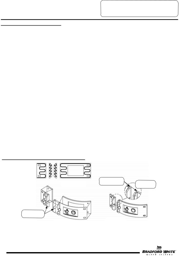
InnerDoor GasketReplacementProcedure
RECOMMENDED |
GASKET OVERLAP |
|
MUST BE AS |
ENLARGED |
|
PATTERN FOR RTV |
SHOWN ±1/32" |
VIEW OF |
SEALANT |
|
FLANGE AREA |
PLACE FLANGE |
VIEW WITH |
SECTIONS FIRST |
|
EXPANDED |
GASKETS IN |
PLACE |
|
VIEW |
|
12
12
SERVICE PROCEDURE RG-I
Inner Door/Gasket Removal,
Inspection, and Replacement
Installation of Inner Door with Gasket
Step 1. Clean anyresidualgasket residue or other debrisfrom combustionchambersurface before installing the innerdoor/gasket assembly.
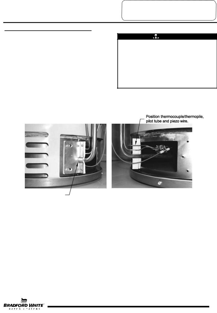
Step 2. Place the left side inner door into position first. Firmlyposition the radiused channelof the innerdooraroundthe feedline. Usingthe two (2)hexdrive screwsfrom Step 3d, secure left side innerdoorin place. DO NOT
OVER TIGHTEN SCREWS.
Step 3. Position thermocouple,pilot tube and piezo wire against left side innerdoorflange gasket.
DO NOT ROUTE THROUGH RADIUSED CHANNEL WITH FEEDLINE.


 WARNING
Stripped fastener connections may allow for seal breach of inner door. A seal breach may result in a fire or explosion causing property damage, personal injury or death. DO NOT overtighten screws in Steps 2, 4, and 5.
If a fastener connection is stripped, contact the manufacturer listed on the water heater rating plate.
Radiused channel for feedline
13
13
SERVICE PROCEDURE RG-I
Inner Door/Gasket Removal, Inspection
Replacement and Reinstallation
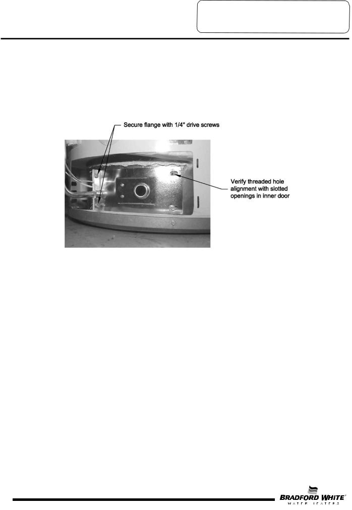
Step 4. Firmly place right side inner door flange against the left side inner door flange and secure with two
(2) 1 / 4 ” hex drive screws from Step 3c. DONOTOVERTIGHTENSCREWS.
Step 5. Align the right side inner door to combustion chamber and verify that the fastener holes of the combustion chamber are aligned with the right side inner door slotted opening. Verify seal integrity around the combustion opening. Secure right side inner door using two (2) 1/4” hex drive screws from Step 3b. DO NOTOVERTIGHTENSCREWS.Verify both left and right sides of the inner door are properly positioned and sealed against the combustion chamber.
Step 6. |
Reconnect the lead wires from combination thermostat/gas valve to resettable thermal switch |
|
(see photo in Step 3). |
|
NOTE: Wire terminations are interchangeable with either resettable thermal switch connections. |
Step 7. |
Replace the outer jacket burner access door. |
Step 8. |
To resume operation, follow the instructions located on the lighting instruction label or the lighting |
|
instructions located in the Installation and Operation Manual. |
14
14
 Loading...