


 Loading...
GAS-FIRED WATER HEATER
A Spanish language version of these instructions is available by contacting the company listed on the rating plate.
La versión espãnola de estas instrucciones se puede obtener al escribirle a la fábrica cuyo nombre aparece en la placa de especificaciones.
INSTALLATION & OPERATION MANUAL
For Flammable Vapor Ignition Resistance
System Equipped Manufactured Home
(Mobile Home) Water Heater
WARNING: If the information in these instructions is not followed exactly, a fire or explosion may result causing property damage, personal injury or death.
FOR YOUR SAFETY
Do not store or use gasoline or other flammable, combustible, or corrosive vapors and liquids in the vicinity of this or any other appliance.
WHAT TO DO IF YOU SMELL GAS
•Do not try to light any appliance.
•Do not touch any electrical switch; do not use any phone in your building.
•Immediately call your gas supplier from a neighbor’s phone. Follow the gas supplier's instructions.
•If you cannot reach your gas supplier, call the fire department.
Installation and service must be performed by a qualified installer, service agency or the gas supplier.
For your family’s comfort, safety and convenience, it is recommended this water heater be installed and serviced by a plumbing professional.
238-46877-00H REV 5/18

CONGRATULATIONS!
You have just purchased one of the finest water heaters on the market today!
This installation, operation and instruction manual will explain in detail the installation and maintenance of your new Gas Water Heater. We strongly recommend that you contact a plumbing professional for the installation of this water heater.
We require that you carefully read this manual, as well as the enclosed warranty, and refer to it when questions arise. If you have any specific questions concerning your warranty, please consult the plumbing professional from whom your water heater was purchased. For your records we recommend that you write the model, serial number and installation date of your water heater in the maintenance section in the back of this manual.
This manual should be kept with the water heater.
Special Flammable Vapor Ignition Resistant System:
This water heater is equipped with a Flammable Vapor Ignition Resistant System. In the event of improper usage or storage of gasoline or other flammable materials in the location where the water heater is installed, the technology will resist ignition of the flammable vapors outside the confines of the water heater.
The Flammable Vapor Ignition Resistant System features:
•Advanced Flame Arrestor Design.
•Re-settable Thermal Switch to prevent burner/pilot operation with restricted airflow.
•Piezo Igniter
•Sight Window to observe operation of pilot and burner.
FOR YOUR SAFETY: Activation of the Flammable Vapor Ignition Resistant System occurs when flammable vapors are drawn into the water heater and are combusted. If flammable vapors are detected:
•Do not try to light any appliance.
•Do not touch any electrical switch; Do not use any phone in your building.
•Leave the premises and immediately call the fire department from a neighbor’s phone. Follow the fire department’s instructions.
Once the flammable vapor has been evacuated, contact your plumbing professional or the manufacturer for further instructions. Replacement of a Flammable Vapor Ignition Resistant System equipped water heater due to a flammable vapor shutdown is not covered under the terms of the limited warranty.
2

TABLE OF CONTENTS |
|
|
Page |
GENERAL INFORMATION........................................................... |
4 |
INSTALLATION ............................................................................ |
5 |
Locating The Water Heater ................................................... |
5 |
Minimum Clearances ............................................................ |
7 |
Venting................................................................................... |
8 |
Combustion Air Supply......................................................... |
9 |
Water Connections................................................................ |
10 |
Gas Connections................................................................... |
13 |
Gas Conversion Instructions ............................................... |
14 |
GENERAL OPERATION............................................................... |
23 |
Lighting and Shutdown Instructions ................................... |
24 |
Thermostat Adjustment ........................................................ |
25 |
Burner Flame Check ............................................................. |
27 |
MAINTENANCE............................................................................ |
27 |
TYPICAL INSTALLATION ............................................................ |
30 |
PARTS LIST & DRAWING ........................................................... |
31 |
NOTES ........................................................................................ |
32 |
3

GENERAL INFORMATION
This gas-fired w ater heater is design certified by the CSA International under the applicable American National Standard, Z21.10.1 or Z21.10.3-(as indicated on the rating plate) and CSA 4.1-(as indicated on the rating plate).
This w ater heater must be installed in accordance w ith local codes. In the absence of local codes, it must be installed in compliance w ith the National Fuel Gas Code (ANSI Z223.1-Latest Edition), or in Canada CAN/CGA B149.1 Natural Gas Installation Code (Latest Edition) or CAN/CGA B149.2 Propane Installation Code (Latest Edition). The w arranty for this w ater heater is in effect only w hen the w ater heater is installed, adjusted, and operated in accordance w ith these Installation and Operating Instructions. The manufacturer w ill not be liable for any damage resulting from alteration and/or failure to comply w ith these instructions. This w ater heater must be installed in accordance w ith The Federal Manufactured Home Construction And Safety Standard Title 24 CRF. part 3280 or CAN/CSA Z240 MH series, mobile home. This w ater heater is designed certified for installation in a manufactured home (mobile home) only and must be installed in an enclosure that w ill completely separate the w ater heater combustion and venting systems from its interior. The w ater heater enclosure access door must be on the outside w all of the manufactured home (mobile home) only. Access to the w ater heater enclosure from the inside of the manufactured home (mobile home) is not permitted.
CSA International has tested a representative sample of this w ater heater design for its safety of operation. The CSA listing of this w ater heater includes the field installation of the follow ing components: roof jack and heater tie dow n materials. These components for field installation may have been shipped w ith this heater and must be installed according to these instructions. No other components are approved for use w ith this w ater heater.
This w ater heater has been designed and certified for the purpose of heating potable w ater. The installation and use of this w ater heater for any purpose other than the heating of potable w ater may cause damage to the w ater heater, create a hazardous condition, and nullify the w arranty.
 CAUTION
Incorrect operation of this appliance may create a hazard to life and property and will nullify the warranty.
 WARNING
Prior to connecting the gas supply line to a gas fired water heater, ensure that the gas supply line does not have moisture/water or dirt/scale inside the gas line. Commonly this check is done at the lowest point in the gas distribution system prior to gas burning appliances.
Do not use this appliance if any external part to the tank has been submerged in w ater. You should contact a qualified service technician to inspect the appliance
and to replace any part of the control system including the combination gas control w hich has been submerged in w ater. See the Gas Connections section of this manual before servicing or replacing a w ater heater that has had any external part to the tank submerged In w ater.
4

General Information continued-
 DANGER
Do not store or use gasoline or other flammable, combustible, or corrosive vapors and liquids in the vicinity of this or any other appliance.
To comply with NSF requirements this water heater is to be:
a)Sealed to the floor with sealant, in a smooth and easily cleanable way, or
b)Installed with an optional leg kit that includes legs and/or extensions that provide a minimum clearance of 6” beneath the water heater.
This water heater has been manufactured for operation at altitudes from sea level to 2000 feet (610m) (unless otherwise specified on the water heater). For use of this appliance at an elevation greater than 2000 feet (610m), contact the dealer or manufacturer listed on the rating plate for information on any necessary modification. Uncorrected operation of this appliance may create a hazard to life and property.
IMPORTANT
Before proceeding, please inspect the water heater and components for possible damage. DO NOT install any damaged components. If damage is evident then please contact the supplier where the water heater was purchased or the manufacturer listed on the rating plate for replacement parts.
Make sure that you check the rating plate and combination gas control on the water heater to be certain that the type of gas being supplied corresponds with the marking on the rating plate and combination gas control.
A sacrificial anode(s) is used to extend tank life. Removal of any anode, except for inspection and/or replacement, will nullify the warranty. In areas where water is unusually active, an odor may occur at the hot water faucet due to a reaction between the sacrificial anode and impurities in the water. If this should happen, an alternative anode(s) may be purchased from the supplier that installed this water heater. This will minimize the odor while protecting the tank. Additionally, the water heater should be flushed with appropriate dissolvers to eliminate any bacteria.
 WARNING
This product contains one or more chemicals known to the State of
California to cause cancer, birth defects, or reproductive harm.
INSTALLATION
Locating the Water Heater

 WARNING
Water heaters are heat producing appliances. To avoid damage or injury there shall be no materials stored against the w ater heater or vent-air intake system and proper care must be taken to avoid unnecessary contact (especially by children) w ith the w ater heater and vent-air intake components. UNDER NO
CIRCUMSTANCES SHALL FLAMMABLE MATERIALS, SUCH AS GASOLINE OR PAINT THINNER BE USED OR STORED IN THE VICINITY OF THIS WATER HEATER, VENT-AIR INTAKE SYSTEM OR IN ANY LOCATION FROM WHICH FUMES COULD REACH THE WATER HEATER OR VENT-AIR INTAKE SYSTEM.
5

Installation continued-
DO NOT install the water heater in any location where gasoline or flammable vapors are likely to be present. This water heater MUST be installed indoors out of the wind and weather.
The location of this water heater is of the utmost importance. Before installing this water heater, read the installation section of these instructions. After reading these installation and operating instructions, select a location for the water heater where the floor is level and is easily accessible to gas and water supply lines. DO NOT locate the water heater where water lines could be subjected to freezing temperatures.
Make sure the cold water pipes are not located directly above the gas control so that condensate during humid weather does not drip on the controls.
Water heater corrosion and component failure can be caused by the heating and breakdown of airborne chemical vapors. Examples of some typical compounds that are potentially corrosive are: spray can propellants, cleaning solvents, refrigerator and air conditioning refrigerants, swimming pool chemicals, calcium and sodium chloride, waxes and process chemicals. These materials are corrosive at very low concentration levels with little or no odor to reveal their presence. NOTE: DAMAGE TO THE
WATER HEATER CAUSED BY EXPOSURE TO CORROSIVE VAPORS IS NOT COVERED BY THE WARRANTY. DO NOT OPERATE THE WATER HEATER IF EXPOSURE HAS OR WILL OCCUR. DO NOT STORE ANY POTENTIALLY CORROSIVE COMPOUNDS IN THE VICINITY OF THE WATER HEATER.
For exact venting specifications, please consult the Venting section, located on page 8, of these Installation and Operating Instructions.
Note: For California installation this water heater must be braced, anchored, or strapped to avoid falling or moving during an earthquake. See instructions for correct installation procedures. Instructions may be obtained from DSA Headquarters Office, 1102 Q Street, Suite 5100, Sacramento, CA 95811.


 WARNING
Liquefied petroleum gases/propane gas are heavier than air and will remain at floor level if there is a leak. Basements, crawl spaces, closets and areas below ground level will serve as pockets for accumulation of leaking gas.
Before lighting, smell all around the appliance area for gas. Be sure to smell next to the floor.
IF YOU SMELL GAS:
•Do not try to light any appliance.
•Do not touch any electric switch; do not use any telephone in your building.
•Immediately call your gas supplier from a neighbor’s telephone. Follow the gas supplier’s instructions.
•If you cannot reach your gas supplier, call the fire department.
DO NOT OPERATE APPLIANCE UNTIL LEAKAGE IS CORRECTED!
6

Installation continued-
 WARNING
DO NOT ATTEMPT TO LIGHT ANY GAS APPLIANCE IF YOU ARE NOT CERTAIN OF THE FOLLOWING:
•Liquefied petroleum gases/propane gas and natural gas have an odorant added by the gas supplier that aids in detection of the gas.
•Most people recognize this odor as a “sulfur” or “rotten egg” smell.
•Other conditions, such as “odorant fade” can cause the odorant to diminish in intensity, or “fade”, and not be as readily detectable.
•If you have a diminished sense of smell, or are in any way unsure of the presence of gas, immediately contact your gas supplier from a neighbor’s telephone.
•Gas detectors are available. Contact your gas supplier or plumbing professional for more information.
This water heater must be located in an area where leakage of the tank, water line connections, or the combination temperature and pressure relief valve will not result in damage to the area adjacent to the water heater or to lower floors of the structure. When such locations cannot be avoided, suitable drain pan, adequately drained, must be installed under the water heater. The drain pan must have a minimum length and width of at least 4 in. (10.2 cm) greater than the diameter of the water heater and must not restrict proper combustion air flow to the water heater. The drain pan, as described above, can be purchased from your plumbing professional. The drain pan must be piped to an adequate drain. The piping must be at least 3/4 inch (1.9 cm) in diameter and pitched for proper drainage.
It is recommended that a minimum clearance of 4 inches (10.2 cm) be provided on the side of the water heater for servicing and maintenance of the combination temperature and pressure relief valve.
Minimum Clearances


 WARNING
Failure to adhere to these installation and operating instructions may create a hazard to life and property and will nullify the warranty.
This installation must allow access to the front of the water heater and adequate clearance must be provided for servicing and operating this water heater. The water heater may be installed on either a combustible or non-combustible floor. If the water heater is to be installed directly on carpeting, it must be installed on top of a metal or wood panel (or equivalent) extending beyond the full width and depth of the appliance by at least 3 inches (7.6 cm) in any direction or, if the appliance is to be installed in an alcove or closet, the entire floor must be covered by the panel, increase distances to provide clearance for servicing.
7
Installation continued-
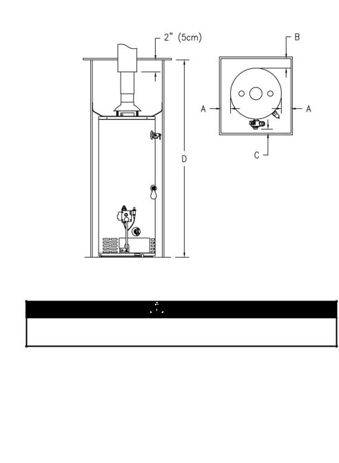
Minimum Clearances From
Combustible Materials
A 0’’ (0cm) Left, 2’’ (5.08cm) Right (113.6 Liters Only)
B 0’’ (0cm)
C 4’’ (10.16cm) D 78’’ (1.98m) m VENT ----
Figure 1
Venting


 WARNING
The vent system must be installed properly. Failure to properly install the vent system could result in property damage, personal injury, or death.
Make certain the flue baffle is in place and centered in flue tube. Place the draft diverter over the flue opening at the top of the water heater by inserting the tips of the draft diverter legs into the four (4) holes provided in the water heater top. Cut a 7 1/4 inch (18.5cm) diameter hole in the ceiling and roof directly above the flue of the w ater heater. Center the w ater heater beneath the 7 1/4 inch (18.5cm) diameter holes in the roof and ceiling for proper alignment of the draft diverter and roof jack vent. Apply non-hardening mastic on the roof, around the previously cut hole, to form a w eather seal w ith the flashing of the gas vent roof jack assembly. Insert gas vent roof jack assembly from above and fasten the flashing to the roof through the pre-punched holes in the flashing. Note: Only the roof jacks listed in Figure 2 can be used on this water heater. Apply additional non-hardening mastic to complete the w eather seal. Slip the 3inch (7.62cm) vent connector extension that is shipped telescoped, into the gas vent roof jack assembly dow n onto the draft diverter that is secured to the top of the w ater heater and fasten w ith the tw o (2) sheet metal screw s provided.
8

TYPICAL INSTALLATION (VENTING)
Figure 2
Combustion Air Supply


 WARNING
Liquefied petroleum gases/propane gases are heavier than air and will remain at floor level if there is a leak. Basements, crawl spaces, closets and areas below ground level will serve as pockets for accumulation of leaking gas. Before lighting, smell all around the appliance area for gas. Be sure to smell next to the floor.
IF YOU SMELL GAS:
•Do not try to light any appliance.
•Do not touch any electric switch; do not use any telephone in your building.
•Immediately call your gas supplier from a neighbor’s telephone. Follow the gas supplier’s instructions.
•If you cannot reach your gas supplier, call the fire department.
DO NOT OPERATE APPLIANCE UNTIL LEAKAGE IS CORRECTED!
IMPORTANT
The flow of combustion and ventilating air must not be obstructed.
9

Combustion Air Supply continued-
All combustion air must be supplied from outdoors by one of the following installation methods and as illustrated in Figure 2. The flow of combustion and ventilating air must not be obstructed. Adequate air must be supplied for combustion and ventilation. An insufficient supply of air will cause recirculation of combustion products resulting in air contamination that may be hazardous to life. Such a condition often will result in a yellow, luminous burner flame, causing carboning or sooting of the combustion chamber, burners and flue tubes with possible damage to the heater.
A minimum 34 in2 (86.4cm2) opening area is required to supply fresh air to the water heater for combustion. Cut a 4” x 8 1/2” (10.2cm x 21.6cm) rectangular opening in the outside access door panel with the bottom side of the opening being 6” (15.3cm) from the bottom access door panel. A protective cover for this fresh air opening is suggested to resist the entrance of rodents.


 WARNING
Be sure protective cover still allows adequate fresh air opening area.
The water heater is to be secured in place using the supplied sheet metal strapping and screws. Fasten the base of the water heater to the floor using the screws provided. The perforated metal strapping must be fastened to the top of the water heater and to the adjacent walls with the screws provided (See Figure 2).
Water Connections
NOTE: BEFORE PROCEEDING WITH THE INSTALLATION, CLOSE THE MAIN WATER SUPPLY VALVE.
After shutting off the main water supply, open a faucet to relieve the water line pressure to prevent any water from leaking out of the pipes while making the water connections to the water heater. After the pressure has been relieved, close the faucet. The COLD water inlet is identified on the side of the water heater and HOT water outlet is identified on the top of the water heater. The fittings at the cold water inlet and hot water outlet are dielectric waterway fittings with 3/4” NPT male thread. Make the proper plumbing connections between the water heater and the plumbing system to the house. Install a shut-off valve in the cold water supply line.
 CAUTION
If sw eat fittings are to be use, DO NOT apply heat to the nipples on the w ater heater. Sw eat the tubing to the adapter before fitting the adapter to the w ater connections. It is imperative that heat is not applied to the nipples containing a plastic liner.
10
Loading...