


Installation and Operation Instructions |
Document 1244A |
|
|
Installation and Operation
Instructions for
Hydronic Boiler
Model BMT2H
Water Heater
Model BMT2V
Sizes 200, 300, 400
FOR YOUR SAFETY: This product must be installed and serviced by a professional service technician, qualified in hot water boiler installation and maintenance. Improper installation and/or operation could create carbon monoxide gas in flue gases which could cause serious injury, property damage, or death. Improper installation and/or operation will void the warranty. For indoor installations, as an additional measure of safety, Bradford White strongly recommends installation of suitable Carbon Monoxide detectors in the vicinity of this appliance and in any adjacent occupied spaces.
 WARNING
If the information in this manual is not followed exactly, a fire or explosion may result causing property damage, personal injury or loss of life.
Do not store or use gasoline or other flammable vapors and liquids in the vicinity of this or any other appliance.
WHAT TO DO IF YOU SMELL GAS
•Do not try to light any appliance.
•Do not touch any electrical switch; do not use any phone in your building.
•Immediately call your gas supplier from a nearby phone. Follow the gas supplier's instructions.
•If you cannot reach your gas supplier, call the fire department.
Installation and service must be performed by a qualified installer, service agency, or gas supplier.
 AVERTISSEMENT Assurez-vous de bien suivres les instructions données dans cette notice pour réduire au minimum le risque d’incendie ou d’explosion ou pour éviter tout dommage matériel, toute blessure ou la mort.
Ne pas entreposer ni utiliser d’essence ni d’autres vapeurs ou liquides inflammables dans le voisinage de cet appareil ou de tout autre appareil.
QUE FAIRE SI VOUS SENTEZ UNE ODEUR DE GAZ:
•Ne pas tenter d’allumer d’appareils.
•Ne touchez à aucun interrupteur. Ne pas vous servir des téléphones dansle bâtiment où vous trouvez.
•Appelez immédiatement votre fournisseur de gaz depuis un voisin. Suivez les instructions du fournisseur.
•Si vous ne pouvez rejoindre le fournisseur de gaz, appelez le sservice des incendies.
L’installation et l’entretien doivent être assurés par un installateur ou un service d’entretien qualifié ou par le fournisseur de gaz.
H2357900-
238-49221-00B REV 7/14
Page 2 |
Bradford White Corp. |
|
|
|
|
TABLE OF CONTENTS
SECTION 1. General Information
1.1 |
Introduction....................................................... |
3 |
1.2 |
Model Identification.......................................... |
4 |
1.3 |
Warranty........................................................... |
4 |
1.4 |
Dimensions....................................................... |
4 |
1.5 |
Locating the Appliance..................................... |
4 |
1.6Locating Pump-Mounted Water Heater
with Respect to Storage Tank(s)...................... |
7 |
1.7Locating Pump-Mounted Boiler with
Respect to Return/Supply Header.................... |
7 |
1.8Locating Appliance for Correct Horizontal Vent/
|
Ducted Air Distance From Outside Wall........... |
7 |
SECTION 2. Venting and Combustion Air |
||
2.1 |
Combustion Air................................................. |
8 |
2.1.1 |
Combustion Air From Room............................. |
8 |
2.1.2 |
Intake Combustion Air...................................... |
9 |
2.2 |
Venting............................................................. |
9 |
2.2.1 |
Vent Categories................................................ |
9 |
2.2.2 |
Category I Vent................................................. |
9 |
2.2.3 |
Common Venting Systems............................... |
9 |
2.2.4 |
Category III Vent............................................. |
10 |
2.3 |
Locating Vent & Combustion Air Terminals.... |
10 |
2.3.1 |
Side Wall Vent Terminal.................................. |
10 |
2.3.2 |
Side Wall Combustion Air Terminal................ |
13 |
2.3.3 |
Vertical Vent Terminal..................................... |
13 |
2.3.4 |
Vertical Combustion Air Terminal.................... |
13 |
2.4 |
Common Vent Test – Boilers.......................... |
13 |
2.5 |
Vent Terminals for Outdoor Units................... |
14 |
SECTION 3. Gas Supply and Piping |
|
|
3.1 |
Gas Supply and Piping................................... |
15 |
SECTION 4A. Water Connections – |
|
|
|
Boiler |
|
4A.1 |
Heating System Piping: |
|
|
Hot Supply Connections – Boiler.................... |
16 |
4A.2 |
Cold Water Make-Up – Boiler......................... |
16 |
4A.3 |
Water Flow Requirements – Boiler................. |
16 |
4A.4 |
Freeze Protection – Boiler.............................. |
16 |
SECTION 4B. Water Connections – |
|
|
|
Water Heater |
|
4B.1 |
Water System Piping – Water Heater............. |
20 |
4B.2 |
Hot Water Supply Piping – Water Heater....... |
20 |
4B.3 |
Water Flow Requirements – Water Heater..... |
20 |
4B.4 |
Combined Water (potable) |
|
|
Heating and Space Heating........................... |
20 |
4B.5 |
Freeze Protection – Water Heater.................. |
21 |
SECTION 5. Electrical Connections
5.1 |
Main Power.................................................... |
24 |
5.2 |
Field Wiring ................................................... |
24 |
SECTION 6. Operating Instructions |
|
|
6.1 |
Filling the Boiler System................................. |
26 |
6.2 |
Operating Temperature Control...................... |
26 |
6.3 |
External Boiler Operations............................. |
28 |
6.4 |
Sequence of Operation.................................. |
28 |
6.5Ignition Control Reaction to Air Flow/
|
Blocked Vent Pressure Switch....................... |
28 |
6.6 |
Operating the Burner and Set Up................... |
29 |
6.6.1 |
Set Up for 0 to 2500 Feet Altitude.................. |
29 |
6.6.2 |
High Altitude Adjustment and Set Up............. |
29 |
6.7 |
Shutting Down the Brute Deluxe ................... |
30 |
6.8 |
To Restart the Brute Deluxe .......................... |
30 |
SECTION 7. Maintenance |
|
|
7.1 |
System Maintenance...................................... |
30 |
7.2Appliance Maintenance and
|
Component Description.................................. |
30 |
7.2.1 |
Burners........................................................... |
31 |
7.2.2 |
Filter............................................................... |
31 |
7.2.3 |
Gas Valves..................................................... |
31 |
7.2.4 |
Manual Reset High Limit Control.................... |
31 |
7.2.5 |
Ignition Control............................................... |
31 |
7.2.6 |
Ignitor............................................................. |
31 |
7.2.7 |
Transformer.................................................... |
31 |
7.2.8 |
Flow Switch.................................................... |
31 |
7.2.9 |
Heat Exchanger Coil...................................... |
32 |
SECTION 8. Trouble Shooting |
|
|
8.1 |
Resolving Lockouts........................................ |
33 |
8.2 |
Delayed Ignition – Possible Causes............... |
33 |
8.3 |
Short Cycling – Boiler..................................... |
33 |
8.4 |
Short Cycling – Water Heater......................... |
33 |
8.5 |
High Gas Consumption.................................. |
33 |
SECTION 9. Replacement Parts |
|
|
9.1 |
General Information........................................ |
34 |
9.2 |
Parts List........................................................ |
34 |

Brute Deluxe (200, 300, 400) |
Page 3 |
|
|
|
|
SECTION 1.
General Information
USING THIS MANUAL – Because the Brute Deluxe Boilers and Brute Deluxe Water Heaters are identical appliances, with the exception of materials of manufacture, labels and ultimate use application, this manual provides information for the proper installation, operation and maintenance of both products. Where differences exist between the application of the appliances and their operation, the sections pertinent to only one appliance or the other will be so identified.
In the Commonwealth of Massachusetts, this appliance must be installed by a licensed plumber or gas fitter.
1.1Introduction
This manual provides information necessary
for the installation, operation, and maintenance of Bradford White's Brute Deluxe copper tube
appliances, sizes 200-400 MBTU/hr (larger models are covered in a separate manual). Read it carefully before
installation.
All application and installation procedures should be reviewed completely before proceeding with the installation. Consult the Bradford White. factory, or local factory representative, with any issues or questions regarding this equipment. Experience has shown that most operating issues are caused by improper installation.
The Brute Deluxe appliance is protected against over pressurization. A pressure relief valve is fitted to all appliances. It is installed on the outlet header, at the water outlet of the appliance.
IMPORTANT: The inlet gas pressure to the appliance must not exceed 13 in. w.c. (3.2 kPa).
All installations must be made in accordance with:
1)In the U.S., the " National Fuel Gas Code "ANSI Z223.1/NFPA54, Latest Edition and all applicable local codes as required by the Authorities Having Jurisdiction (AHJ), or
2)In Canada, the "Natural Gas and Propane Installation Code", CSA B149.1, latest edition and all applicable local codes as required by the AHJ.
All electrical wiring is to be done in accordance with:
1). In the U.S., the "National Electrical Code" (NEC), ANSI/NFPA 70, latest Edition and all applicable local codes as required by the AHJ, or
2). In Canada, the “Canadian Electrical Code - Part 1”, CSA STD. C22.1 and all applicable local codes as required by the AHJ.
This appliance must be electrically grounded in accordance with the applicable codes and standards referenced above.
 WARNING
To minimize the risk of electric shock, fire or other hazards which could result in property damage, injury, or death. The Brute Deluxe hydronic, boiler or water heater must be installed in accordance with the procedures detailed in this manual, or the Bradford White. warranty may be voided. The installation must conform to the requirements of the local jurisdiction having authority, and, in the United States, to the latest edition of the National Fuel Gas Code, ANSI Z223.1/NFPA54. In Canada, the installation must conform to
the latest edition of the Natural Gas and Propane Installation Code, CSA B149.1 and/ or applicable local codes. Where required by the authority having jurisdiction, the installation of Brute Deluxe appliances must conform to the Standard for Controls and Safety Devices for Automatically Fired Boilers, ANSI/ASME CSD-1. Any modifications to the boiler, its gas controls, or wiring may void the warranty. If field conditions require modifications, consult the factory representative before initiating such modifications.
 AVERTISSEMENT
Afin de minimiser les risques d'électrocution, d'incendie ou d'autres dangers qui pourraient entraîner des dommages aux biens, des blessures ou la mort. Le Brute Deluxe hydronique, une chaudière ou un chauffe-eau doit être installé conformément aux procédures détaillées dans ce manuel, ou le chauffage Bradford White Systèmes garantie peut être annulée. L'installation doit être conforme aux exigences de la juridiction locale ayant l'autorité, et, aux ÉTATS-UNIS , à la dernière édition du National gaz combustible Code, ANSI Z223.1/ NFPA54. Au Canada, l'installation doit être conforme à la dernière édition du gaz naturel
et propane Code d'Installation, CSA B149.1 et/ ou codes locaux. Lorsque requis par l'autorité ayant juridiction, l'installation de Brute Deluxe les appareils doivent être conformes à la norme pour les contrôles et les dispositifs de sécurité automatiquement pour chaudières, ANSI/ASME LA CDD-1. Toute modification apportée à la chaudière, de ses commandes de gaz, ou le câblage peut annuler la garantie.
Page 4 |
|
|
|
|
|
|
|
|
|
|
|
|
|
|
|
|
|
|
|
|
|
|
|
|
|
|
|
|
|
|
|
|
|
|
|
|
|
Bradford White Corp. |
|
||||||||||||||
|
|
|
|
|
|
|
|
|
|
|
|
|
|
|
|
|
|
|
|
|
|
|
|
|
|
|
|
|
|
|
|
|
|
|
|
|
|
|
|
|
|
|
|
|
|
|
|
|
|
|
|
|
|
|
|
|
|
|
|
|
|
|
|
|
|
|
|
|
|
|
|
|
|
|
|
|
|
|
|
|
|
|
|
|
|
|
|
|
|
|
|
|
|
|
|
|
|
|
|
|
|
|
|
|
|
|
|
1 |
2 |
3 |
|
4 |
5 |
|
6 |
7 |
8 |
9 |
|
|
10 |
11 |
|
|
|
12 |
|
13 |
|
14 |
|
15 |
|
16 |
|
|
|||||||||||||||||||||||||
|
|
|
|
|
|
|
|
|
|
|
|
|
|
|
|
|
|
|
|
|
|
|
|
|
|
|
|
|
|
|
|
|
|
|
|
|
|
|
|
|
|
|
|
|
|
|
|
|
|
|
|
|
|
|
B |
M |
|
T |
|
2 |
|
|
|
|
|
|
|
|
|
|
|
|
|
|
|
|
|
|
C |
|
|
|
|
|
|
|
|
2 |
|
|
|
|
|
|
|
|
|
|
|
|
|
|
|
|
|
||
|
|
|
|
|
|
|
|
|
|
|
|
|
|
|
|
|
|
|
|
|
|
|
|
|
|
|
|
|
|
|
|
|
|
|
|
|
|
|
|
|
|
|
|
|
|
|
|
|
|
|
|
|
|
|
|
|
|
|
|
|
|
|
|
|
|
|
|
|
|
|
|
|
|
|
|
|
|
|
|
|
|
|
|
|
|
|
|
|
|
|
|
|
|
|
|
|
|
||||||||||
|
|
|
SERIES |
|
|
USAGE |
|
|
|
SIZE |
|
|
|
FUEL |
|
|
LOCATION |
|
|
FIRING |
|
REVISION |
|
|
HEAT |
|
OPTIONS |
|
|
PUMP |
|
||||||||||||||||||||||
|
B M T 2 |
|
|
|
H |
|
0 |
2 |
0 |
0 |
|
|
N |
|
|
|
C |
|
|
MODE |
|
2 |
|
|
EXCHANGER |
|
|
CODE |
|
OPTIONS |
|
||||||||||||||||||||||
|
|
|
|
|
|
|
|
|
V |
|
0 |
3 |
0 |
0 |
|
|
P |
|
|
|
|
|
|
|
|
|
C |
|
|
|
|
|
|
|
B |
|
|
|
X |
|
|
X |
|
||||||||||
|
|
|
|
|
|
|
|
|
|
|
|
|
|
|
|
|
|
|
|
|
|
|
|
|
|
|
|
|
|
|
|||||||||||||||||||||||
|
|
|
|
|
|
|
|
|
|
|
|
|
0 |
4 |
0 |
0 |
|
|
|
|
|
|
|
|
|
|
|
|
|
K |
|
|
|
|
|
|
|
C |
|
|
|
L |
|
|
N |
|
|||||||
|
|
|
|
|
|
|
|
|
|
|
|
|
|
|
|
|
|
|
|
|
|
|
|
|
|
|
|
|
|
|
|
|
|||||||||||||||||||||
|
|
|
|
|
|
|
|
|
|
|
|
|
|
|
|
|
|
|
|
|
|
|
|
|
|
|
|
|
|
|
|
|
|
|
|
|
|
|
|
N |
|
|
|
|
|
|
|
S |
|
||||
|
|
|
|
|
|
|
|
|
|
|
|
|
|
|
|
|
|
|
|
|
|
|
|
|
|
|
|
|
|
|
|
|
|
|
|
|
|
|
|
|
|
|
|
|
|
||||||||
|
|
|
|
|
|
|
|
|
|
|
|
|
|
|
|
|
|
|
|
|
|
|
|
|
|
|
|
|
|
|
|
|
|
|
|
|
|
|
|
P |
|
|
|
|
|
|
|
G |
|
||||
|
|
|
|
|
|
|
|
|
|
|
|
|
|
|
|
|
|
|
|
|
|
|
|
|
|
|
|
|
|
|
|
|
|
|
|
|
|
|
2 |
|
|
|
|
|
|
|
|
|
|
|
|
||
|
|
|
|
|
|
|
|
|
|
|
|
|
|
|
|
|
|
|
|
|
|
|
|
|
|
|
|
|
|
|
|
|
|
|
|
|
|
|
5 |
|
|
|
|
|
|
|
|
|
|
|
|
||
|
|
|
|
|
|
|
|
|
|
|
|
|
|
|
|
|
|
|
|
|
|
|
|
|
|
|
|
|
|
|
|
|
|
|
|
|
|
|
|
|
|
|
|
|
|
|
|
|
|
|
|
|
|
1.2Model Identification
Consult the rating plate on the unit. The
following information describes the model number structure.
Model Character Designation
1-4 Model Series Designation
B M T 2 = Bradford White, Brute Deluxe
5Usage
H = Hydronic
V = Volume Water
6-9 Size
0 |
2 |
0 |
0 = 199,900 BTU/h input |
0 |
3 |
0 |
0 = 300,000 BTU/h input |
0 |
4 |
0 |
0 = 399,900 BTU/h input |
10Fuel
N = Natural Gas P = Propane
11Location
C = Indoor and Outdoor
12Firing Mode
C = On-Off (standard) K = Two-stage (optional)
13Revision
2 = Revision Level 2
14Heat Exchanger
B = Glass-lined CI / copper / brz trim (std. MT2V) C = Glass-lined cast iron / copper (std. MT2H)
N = Glass-lined cast iron / cu-nickel
P = Glass-lined cast iron / cu-nickel / brz trim
2 = Glass-lined cast iron / copper, brz trim, HLW 5 = Glass-lined cast iron / cu-nickel / brz, HLW
15Options Code
X = Standard unit
L = Low temperature control (std. MT2V)
16Pump Options
X = No Pump
N = Pump mounted, normal water, Taco
S = Pump mounted, soft water pump (MT2V only), Taco
G = Pump mounted, normal water, Grundfos
1.3Warranty
Bradford White's Brute Deluxe appliances are
covered by a limited warranty. The owner should fill out the warranty registration card and return it to Bradford White.
All warranty claims must be made to an authorized Bradford White. representative or directly to the factory. Claims must include the serial number and model (this information can be found on the rating plate), installation date, and name of the installer. Shipping costs are not included in the warranty coverage.
Some accessory items are shipped in separate packages. Verify receipt of all packages listed on the packing slip. Inspect everything for damage immediately upon delivery, and advise the carrier of any shortages or damage. Any such claims should be filed with the carrier. The carrier, not the shipper, is responsible for shortages and damage to the shipment whether visible or concealed.
1.4Dimensions
See Figures 1A and 1B.
1.5Locating the Appliance
The appliance should be located to provide
clearances on all sides for maintenance and inspection.
It should not be located in an area where leakage of any connections will result in damage to the area adjacent to the appliance or to lower floors of the structure.
When such a location is not available, it is recommended that a suitable drain pan, adequately drained, be installed under the appliance.
The appliance is design certified by CSAInternational for installation on combustible flooring; in basements; in closets, utility rooms or alcoves.
Brute Deluxe Boilers or Water Heaters must never be installed on carpeting. The location for the appliance should be chosen with regard to the vent pipe lengths and external plumbing. The unit shall be installed such that the gas ignition system components are protected from water (dripping, spraying, rain, etc.) during operation and service (circulator replacement, control replacement, etc.). When vented vertically, the

Brute Deluxe (200, 300, 400) |
|
|
|
|
Page 5 |
|||||||||||||||
|
|
|
|
|
|
|
|
|
|
|
|
|
|
|
|
|
|
|
|
|
|
|
|
|
|
|
|
|
|
|
|
|
|
|
|
|
|
|
|
|
|
|
|
|
|
|
|
|
|
|
|
|
|
|
|
|
|
|
|
|
|
|
|
|
|
|
|
|
|
|
|
|
|
|
|
|
|
|
|
|
|
|
|
|
|
|
|
|
|
|
|
|
|
|
|
|
|
|
|
|
|
|
|
|
|
|
|
|
|
|
|
|
|
|
|
|
|
|
|
|
|
|
|
|
|
|
|
|
|
|
|
|
|
|
|
|
|
|
|
|
|
|
|
|
|
|
|
|
|
|
|
|
|
|
|
|
|
|
|
|
|
|
|
|
|
|
|
|
|
|
|
|
|
|
|
|
|
|
|
|
|
|
|
|
|
|
|
|
|
|
|
|
|
|
|
|
|
|
|
|
|
|
|
|
|
|
|
|
|
|
|
|
|
|
|
|
|
|
|
|
|
|
|
|
|
|
|
|
|
|
|
|
|
|
|
|
|
|
|
|
|
|
|
|
|
|
|
|
|
|
|
|
|
|
|
|
|
|
|
|
|
|
|
|
|
|
|
|
|
|
|
|
|
|
|
|
|
|
|
|
|
|
|
|
|
|
|
|
|
|
|
|
|
|
|
|
|
|
|
|
|
|
|
|
|
|
|
|
|
|
|
|
|
|
|
|
|
|
|
|
|
|
|
|
|
|
|
|
|
|
|
|
|
|
|
|
|
|
|
|
|
|
|
|
|
|
|
|
|
|
|
|
|
|
|
|
|
|
|
|
|
|
|
|
|
|
|
Dimensions shown in inches, cm. |
|||
|
|
|
|
|
|
|
|
|
|
|
||||
|
|
|
|
|
|
|
|
|
|
|
||||
|
|
|
|
|
|
|
|
|
|
|
|
|
|
|
|
|
|
|
Combustion Air |
Vent Connection |
Horizontal |
|
|||||||
Model |
|
A |
Connection |
(Cat III) |
|
|||||||||
|
|
C* |
|
|
||||||||||
|
|
|
|
|
B* |
|
|
Vent Pipe Size |
|
|||||
|
|
|
|
|
|
|
|
|
|
|||||
|
in. |
|
cm |
in. |
|
|
cm |
in. |
|
cm |
|
in. |
cm |
|
200 |
20.5 |
|
52 |
4 |
|
10 |
5 |
|
13 |
|
4 |
10 |
|
|
300 |
26.5 |
|
67 |
4 |
|
10 |
6 |
|
15 |
|
5 |
13 |
|
|
400 |
33.6 |
|
85 |
6 |
|
15 |
7 |
|
18 |
|
6 |
15 |
|
|
*Air and vent connections may be on top or back of the Brute Deluxe, and are field convertible.
Figure 1A. Dimensional Data - Non Pump Mounted.

Page 6 |
|
Bradford White Corp. |
|||||
|
|
|
|
|
|
|
|
|
|
|
|
|
|
|
|
|
|
|
|
|
|
|
|
|
|
|
|
|
|
|
|
|
|
|
|
|
|
|
|
|
|
|
|
|
|
|
|
|
|
|
|
|
|
|
|
|
|
|
|
|
|
|
|
|
|
|
|
|
|
|
|
|
|
|
|
|
|
|
|
|
|
|
|
|
|
|
|
|
|
|
|
|
|
|
Dimensions shown in inches, cm. |
|
|
|
|
Combustion Air |
Vent Connection |
Horizontal |
|||
Model |
|
A |
Connection |
(Cat III) |
||||
|
|
C* |
||||||
|
|
|
|
B* |
|
Vent Pipe Size |
||
|
|
|
|
|
|
|||
|
in. |
cm |
in. |
cm |
in. |
cm |
in. |
cm |
200 |
20.5 |
52 |
4 |
10 |
5 |
13 |
4 |
10 |
300 |
26.5 |
67 |
4 |
10 |
6 |
15 |
5 |
13 |
400 |
33.6 |
85 |
6 |
15 |
7 |
18 |
6 |
15 |
*Air and vent connections may be on top or back of the Brute Deluxe, and are field convertible.
Figure 1b. Dimensional Data - Pump Mounted.

Brute Deluxe (200, 300, 400) |
|
|
|
|
|
|
|
|
Page 7 |
||||
|
|
|
|
|
|
|
|
|
|
|
|
|
|
|
|
|
|
|
|
|
|
|
|
|
|
|
|
|
|
|
|
|
|
|
|
|
|
|
|
|
|
Heater |
Vent Collar |
|
Horizontal |
Intake |
Max. Pipe |
Max. No. |
Side Vent |
Side Wall |
|||||
|
Air Collar |
Combustion |
|||||||||||
Size |
|
Size |
|
Vent Pipe |
& Pipe |
Length |
of Elbows |
Terminal |
Air Terminal |
||||
|
|
|
|
|
Diameter |
Diameter |
|
|
|
Part Number |
Part Number |
||
|
in |
|
cm |
|
in |
cm |
in |
cm |
ft |
m |
|
|
|
200 |
5 |
|
13 |
|
4 |
10 |
4 |
10 |
50 |
15 |
3 |
CA003101 |
CA003201 |
300 |
6 |
|
15 |
|
5 |
13 |
4 |
10 |
50 |
15 |
3 |
CA003102 |
CA003201 |
400 |
7 |
|
18 |
|
6 |
15 |
6 |
15 |
50 |
15 |
3 |
CA003103 |
CA003202 |
Table 1. Horizontal Vent / Combustion Air Parameters.
|
Appliance |
Required |
Recommended |
||||||
|
Surface |
Clearance From |
Service Access |
||||||
|
|
|
Combustible Material |
Clearance |
|||||
|
|
|
inches |
|
cm |
inches |
cm |
||
|
Left Side |
1 |
|
|
2.5 |
24 |
|
61 |
|
|
Right Side |
1 |
|
|
2.5 |
24 |
|
61 |
|
|
Top |
1 |
|
|
2.5 |
12 |
|
30 |
|
|
Back |
1 |
|
|
2.5 |
12** |
|
30** |
|
|
Front |
1 |
|
|
2.5 |
36 |
|
91 |
|
|
Vertical |
6* |
|
|
|
|
|
|
|
|
(Category 1) |
|
|
15.2* |
|
|
|
||
|
Vent |
|
|
|
|
|
|
|
|
|
|
|
|
|
|
|
|
|
|
|
Horizontal |
per UL 1738 venting |
|
|
|
||||
|
(Category 3) |
system supplier's |
|
|
|
||||
|
Vent |
instructions |
|
|
|
|
|||
*1" (2.5 cm) when b-vent is used.
**When vent and/or combustion air connects to the back, recommended clearance is 36" (91cm).
Table 2. Clearances.
Brute Deluxe must be located as close as practical to a chimney or outside wall. If the vent terminal and/ or combustion air terminal terminate through a wall, and there is potential for snow accumulation in the local area, both terminals should be installed at an appropriate level above grade such that blockage of the terminal from accumulated debris or precipitation is prevented.
The dimensions and requirements that are shown in Table 2 should be met when choosing the locations for the appliance.
1.6 Locating Pump-Mounted Water Heater
with Respect to Storage Tank(s)
For best results, a pump-mounted Brute Deluxe water heater should be located within 15 feet (4.6m) of the storage tank(s). The pump is sized for 30 feet (9.1m) of piping.
If the appliance must be installed with longer piping runs, then larger diameter pipe or tubing may be acceptable. Consult the factory for assistance.
1.7 Locating Pump-Mounted Boiler with
Respect to Return/Supply Header
For the best results, a pump-mounted Brute Deluxe boiler should be located within 15 feet (4.6m) of the supply and return headers. The pump is sized for 30 feet (9.1m) of piping.
If the appliance must be installed with longer piping runs, then larger diameter tubing may be acceptable. Consult the factory for assistance.
1.8Locating Appliance for Correct Horizontal Vent/Ducted Air Distance
From Outside Wall
The forced draft combustion air blower in the appliance has sufficient power to pull air and vent properly when the guidelines for horizontal air and vent are followed (see Table 1).
NOTE: On some models, the vent collar size is larger than the size of the vent pipe that can be used. Vent collar size and horizontal pipe diameters can be found in Table 1. The larger vent collar
size is to accommodate Category I (vertical) vent systems.
NOTE: When located on the same wall, the Brute Deluxe combustion air intake terminal must be installed a minimum of 12" (30cm) below the exhaust vent terminal and separated by a minimum of 36 inches (91cm) horizontally.
The air intake terminal must be installed high enough to avoid blockage from snow, leaves and other debris.
Section 2.
Page 8 |
Bradford White Corp. |
|
|
|
|
Venting and Combustion Air
 WARNING
For indoor installations, as an additional measure of safety, National Combustion Co. strongly recommends installation of suitable Carbon Monoxide detectors in the vicinity of this appliance and in any adjacent occupied spaces.
 AVERTISSEMENT
Pour des installations intérieures, National Combustion Co. recommande fortement, comme mesure de sécurité supplémentaire, l’installation de détecteurs de monoxyde de carbone adaptés dans le voisinage de l’appareil et dans chacune des pièces habitées adjacentes.
2.1Combustion Air
Brute Deluxe boilers and water heaters must
have provisions for combustion and ventilation air in accordance with the applicable sections addressing requirements for air for combustion and ventilation of the National Fuel Gas Code, ANSI Z223.1. In Canada, the applicable sections of the Natural Gas and Propane Installation Code (CSA B149.1) must be followed. In all cases any and all applicable local installation codes must also be followed.
A Brute Deluxe appliance may receive combustion air from the space in which it is installed, or it can be ducted directly to the unit from the outside. Proper ventilation air must be provided in either case.
2.1.1 Combustion Air From Room
In the United States, the most common requirements specify that the space shall communicate with the outdoors in accordance with method 1 or 2, which follow. Where ducts are used, they shall be of the same cross-sectional area as the free area of the openings to which they connect.
Method 1: Two permanent openings, one commencing within 12 inches (30 cm) of the top and one commencing within 12 inches (30 cm) of the bottom, of the enclosure shall be provided. The openings shall communicate directly, or by ducts, with the outdoors or spaces that freely communicate with the outdoors. When directly communicating with the outdoors, or when communicating to the outdoors through vertical ducts, each opening shall have a minimum free area of 1 square inch per 4000
Btu/hr (5.5 square cm/kW) of total input rating of all equipment in the enclosure. When communicating to the outdoors through horizontal ducts, each opening shall have a minimum free area of not less than 1 square inch per 2000 Btu/hr (11 square cm/kW) of total input rating of all equipment in the enclosure.
Table 3 shows data for this sizing method, for each
Brute Deluxe model.
Method 2: One permanent opening, commencing within 12 inches (30 cm) of the top of the enclosure, shall be permitted. The opening shall directly communicate with the outdoors or shall communicate through a vertical or horizontal duct to the outdoors
or spaces that directly communicate with the outdoors and shall have a minimum free area of 1 square inch per 3000 Btu/hr (7 square cm/kW) of the total input rating of all equipment located in the enclosure. This opening must not be less than the sum of the areas of all vent connectors in the confined space.
Other methods of introducing combustion and ventilation air are acceptable, providing they conform to the requirements in the applicable codes listed above.
In Canada, consult local building and safety codes or, in absence of such requirements, follow CSA B149.1, the Natural Gas and Propane Installation Code.
Boiler |
Each Opening* |
|
Model |
Square inches |
Square cm |
200 |
50 |
323 |
300 |
75 |
484 |
400 |
100 |
645 |
*Net Free Area in Square Inches / Square cm
Area indicated is for one of two openings; one at floor level and one at the ceiling, so the total net free area could be double the figures indicated.
This chart is for use when communicating directly with the outdoors. For special conditions and alternate methods, refer to the latest edition of ANSI Z223.1.
Note: Check with louver manufacturers for net free area of louvers. Correct for screen resistance to the net free area if a screen is installed. Check all local codes applicable to combustion air.
Table 3. Combustion Air Openings.
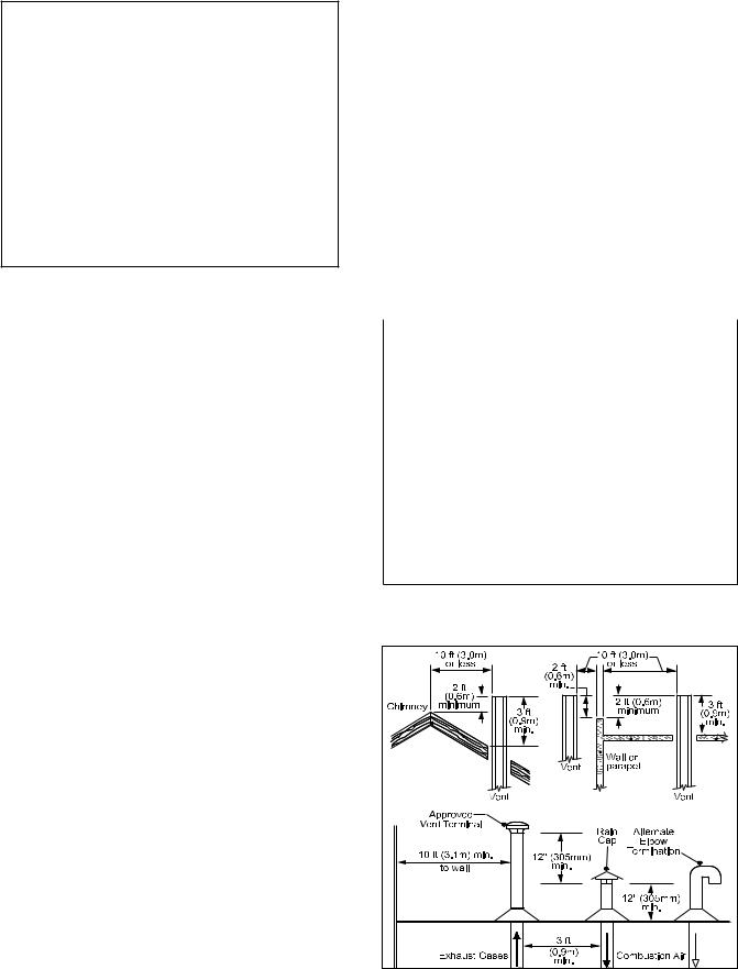
Figure 2. Combustion Air and Vent Through Roof.
Brute Deluxe (200, 300, 400) |
Page 9 |
|
|
|
|
2.1.2 Intake Combustion Air
The combustion air can be taken through the wall, or through the roof. When taken from the wall, it must be taken from out-of-doors by means of the Bradford White horizontal wall terminal (see Table 1). When taken from the roof, a field-supplied rain cap or an elbow arrangement must be used to prevent entry of rain water (see Figure 2).
Use single-wall galvanized pipe, per Table 4, for the combustion air intake (see Table 1 for appropriate size). Route the intake to the heater as directly as possible. Seal all joints with tape. Provide adequate hangers. The unit must not support the weight of the combustion air intake pipe. Maximum linear pipe length allowed is 50 feet (15.2m). Three elbows have been calculated into the 50-foot (15.2m)
linear run. Subtract 10 allowable linear feet (3.0m) for every additional elbow used (see Table 1). When fewer than 3 elbows are used, the maximum linear pipe length allowed is still 50 feet (15.2m).
Term |
Description |
Pipe |
Single-wall galvanized steel pipe, 24 gauge |
|
minimum (either insulated or non-insulated) |
Joint Sealing |
Permanent duct tape or aluminum tape |
Table 4. Required Combustion Air Piping Material.
The connection for the intake air pipe is on the filter box. The Brute Deluxe appliances may have venting and combustion air ducting attached to the top or the back. They are shipped with the connections at the top. For attaching either or both pipes to the back, the mounting flanges are reversible by removing the mounting screws and orienting the flanges in the desired position. Replace the screws after positioning flanges. Run a bead of silicone around the collar and slide the pipe over the collar. Secure with sheet metal screws.
In addition to air needed for combustion, air shall also be supplied for ventilation, including all air required for comfort and proper working conditions for personnel. The Brute Deluxe loses less than 1 percent of its input rating to the room, but other heat sources may be present.
2.2 Venting
2.2.1 Vent Categories
Depending upon desired Brute Deluxe venting, it may be considered a Category I or a Category III appliance. In general, a vertical vent system will be a Category I system. However, in rare instances, a Brute
Deluxe ’s vertical vent system may be considered
Category III. In the U.S., the National Fuel Gas Code (ANSI Z223.1), or in Canada the Natural Gas and Propane Installation Code (CSA B149.1), defines a
Category I vent system, and includes rules and tables to size these vent systems. If the Brute Deluxe ’s
vertical vent system does not satisfy the criteria for Category I venting, it must be vented as a Category III system.
All Brute Deluxe vent systems which discharge horizontally (without the use of a power venter) are considered Category III vent systems.
2.2.2 Category I Vent
When vented as a Category I appliance, the vent system must conform to the National Fuel Gas Code (ANSI Z223.1-Latest Edition) in the U.S., or in Canada, to the Natural Gas and Propane Installation Code (CSA B149.1 latest edition). The vent system must be sized and installed for a Category I FanAssisted Appliance.
If chimney height is greater than 25 feet, or if multiple units are vented into the same vertical vent, a barometric damper must be installed on each appliance, such that the flue draft does not exceed (negative) 0.1 in. w.c.
If using a power venter for any type of Category I venting, the draft should be set between (negative)
0.01 and 0.05 in. w.c.
2.2.3 Common Venting Systems
Brute Deluxe units are Category I fan-assisted when vented vertically and adhering to all applicable codes. Brute Deluxe units are not allowed to be vented into a common horizontal vent system, unless a properly sized vent fan is used, and the common vent system is properly designed by the vent fan manufacturer or a qualified engineer. When common venting Brute Deluxe fan-assisted unit with other appliances through one shared vertical duct called a
“common vent”, special care must be taken by the installer to ensure safe operation. In the event that the common vent is blocked, it is possible, especially for fan-assisted devices, to vent backwards through non-operating appliances sharing the vent, allowing combustion products to infiltrate occupied spaces.
If the appliances are allowed to operate in this condition, serious injury or death may occur.

Page 10 |
Bradford White Corp. |
|
|
|
|
 WARNING
Operation of appliances with a blocked common vent may lead to serious injury or death. Safety devices must be implemented to prevent blocked common vent operation. If safe operation of all appliances connected to a common vent cannot be assured, including prevention of spillage of flue gasses into living spaces, common venting should not be applied, and appliances should each be vented separately.
 AVERTISSEMENT
Le fonctionnement d’appareils connectés à un évent commun bouché peut provoquer de sérieuses blessures corporelles ou la mort. Des dispositifs de sécurité doivent être mis en place pour empêcher que les appareils soient utilisés avec un évent commun bouché. Si un
fonctionnement sécuritaire de tous les appareils reliés à un évent commun et si la prévention des dégagements accidentels de gaz de combustion dans des zones habitées ne peuvent pas être assurés, un évent commun ne doit pas être mis en place et les appareils doivent être munis d’évents individuels séparés.
It is for this reason that, in addition to following proper vent sizing, construction and safety requirements from the National Fuel Gas Code, ANSI Z223.1 or in Canada, from the Natural Gas and Propane Installation Code (CSA B149.1) as well as all applicable local codes, it is required that installers provide some means to prevent operation with a blocked common vent. It is suggested that a blocked vent safety system be employed such that if the switch from one appliance trips due to excessive stack spill or back pressure indicating a blocked vent condition, that all appliances attached to the vent be locked out and prevented from operating. Note that the Brute Deluxe is equipped with a blocked vent safety (pressure) switch, as shipped. However, this safety switch has only been designed and tested to be effective in installations where the Brute Deluxe is vented separately and NOT common vented with other appliances. As an additional precaution, it is
recommended that a Carbon Monoxide (CO) alarm be installed in all enclosed spaces containing combustion appliances. If assistance is required in determining how a blocked vent safety system should be connected to a Bradford White product, please call Applications
Engineering at the Rochester phone number on the back cover of this manual.
Refer to the installation and operating instructions on all appliances to be common vented for instructions, warnings, restrictions and safety requirements. If safe operation of all appliances connected to a common vent cannot be assured,
including prevention of spillage of flue gases into living spaces, common venting should not be applied, and appliances should each be vented separately.
2.2.4 Category III Vent
When the Brute Deluxe is vented with horizontal discharge, it must be installed per this installation manual and the venting system manufacturer’s installation instructions. The vent system must be sealed stainless steel, per Table 5.
Term |
Description |
Pipe |
Must comply with UL Standard 1738 such |
|
as Type AL29-4C Stainless Steel |
|
(either insulated or non-insulated). |
Joint |
Follow vent manufacturer's instructions. |
Sealing |
|
Table 5. Required Horizontal Venting Material.
Route the vent pipe to the heater as directly as possible. Seal all joints and provide adequate hangers as required in the venting system manufacturer’s installation instructions. Horizontal portions of the venting system must be supported to prevent sagging and may not have any low sections that could trap condensate.
The unit must not support the weight of the vent pipe. Horizontal runs must slope downwards not less than ¼ inch per foot (2 cm/m) from the unit to the vent terminal.
L’appareil ne doit pas supporter le poids de la gaine d’évent. Les parties horizontales doivent être installées avec une pente de 2 cm/m (1/4 inch par pied) descendant de l’appareil vers la sortie de l’évent.
Reference Table 1 for the size of the Category III vent system. Up to three elbows can be used with 50 linear feet (15.2m) of pipe. Subtract 10 allowable linear feet (3.0m) for every additional elbow used.
2.3Locating Vent & Combustion Air Terminals
2.3.1 Side Wall Vent Terminal
The appropriate Bradford White side wall vent terminal must be used, and is listed in the installation and operation manual. The terminal provides a means of installing the vent piping through the building wall, and must be located in accordance with ANSI Z223.1/ NFPA 54 and applicable local codes. In Canada, the installation must be in accordance with CSA B149.1 and local applicable codes. Consider the following when installing the terminal:
1.Figure 3 shows the requirements for mechanical vent terminal clearances for the U.S. and Canada.
2.Locate the vent terminal so that vent gases cannot be drawn into air conditioning system inlets.
3.Locate the vent terminal so that vent gases cannot enter the building through doors, windows,
Brute Deluxe (200, 300, 400) |
|
|
|
|
|
|
|
Page 11 |
|||||
|
|
|
|
|
|
|
|
|
|
|
|
|
|
|
|
|
|
|
|
|
|
|
|
|
|
|
|
|
|
|
|
|
|
|
|
|
|
|
|
|
|
|
|
|
|
|
|
|
|
|
|
|
|
|
|
|
|
|
|
|
|
|
|
|
|
|
|
|
|
|
|
|
|
|
|
|
|
|
|
|
|
|
|
|
|
|
|
|
|
|
|
|
|
|
|
|
|
|
|
|
|
|
|
|
|
|
|
|
|
|
|
|
|
|
|
|
|
|
|
|
|
|
|
|
|
|
|
|
|
|
|
|
|
|
|
|
|
|
|
|
|
|
|
|
|
|
|
|
|
|
|
|
|
|
|
|
|
|
|
|
|
|
|
|
|
|
|
|
|
|
|
|
|
|
|
|
|
|
|
|
|
U.S. Installations (see note 1) |
Canadian Installations (see note 2) |
|
A= Clearance above grade, veranda, porch, |
12 inches (30 cm) |
12 inches (30 cm) |
deck, or balcony |
|
|
B= Clearance to window or door that may be opened
Direct Vent Only: 12 inches (30 cm)
Other Than Direct Vent: 4 feet (1.2 m) below or 36 inches (91 cm) to side of opening; 1 foot (30 cm) above opening
C= Clearance to permanently closed window |
See note 4 |
See note 5 |
|
D= Vertical clearance to ventilated soffit located |
|
|
|
|
above the terminal within a horizontal |
See note 4 |
See note 5 |
|
distance of 2 feet (61cm) from the center line of the terminal |
|
|
E= Clearance to unventilated soffit |
See note 4 |
See note 5 |
|
F= Clearance to outside corner |
See note 4 |
See note 5 |
|
G= Clearance to inside corner |
See note 4 |
See note 5 |
|
H= Clearance to each side of center line |
See note 4 |
3 feet (91 cm) within a height 15 feet |
|
|
extended above meter/regulator assembly |
|
above the meter/regulator assembly |
I= |
Clearance to service regulator vent outlet |
See note 4 |
3 feet (91 cm) |
J= |
Clearance to non mechanical air supply |
Direct Vent Only: 12 inches (30 cm) |
|
|
inlet to building or the combustion air inlet |
Other Than Direct Vent: 4 feet (1.2 m) below or |
36 inches (91 cm) |
|
to any other appliance |
to side of opening; 1 foot (30 cm) above opening |
|
K= Clearance to a mechanical air supply inlet |
3 feet (91 cm) above if within 10 feet (3 m) |
6 feet (1.83 m) |
|
|
|
horizontally |
|
L= Clearance above paved sidewalk or paved |
Vent termination not allowed in this location |
Vent termination not allowed in this |
|
|
driveway located on public property |
|
location |
M= Clearance under veranda, porch, deck, |
See note 4 |
12 inches (30 cm) (see note 3) |
|
|
or balcony |
|
|
Notes:
1.In accordance with the current ANSI Z223.1 / NFPA 54 National Fuel Gas Code.
2.In accordance with the current CSA B149.1, Natural Gas and Propane Installation Code.
3.Permitted only if veranda, porch, deck, or balcony is fully open on a minimum of two sides beneath the floor.
4.For clearances not specified in ANSI Z223.1 / NFPA 54, clearance is in accordance with local installation codes and the requirements of the gas supplier.
5.For clearances not specified in CSA B149.1, clearance is in accordance with local installation codes and the requirements of the gas supplier.
Figure 3. Vent Terminal Clearance.

Page 12 |
Bradford White Corp. |
|
|
|
|
gravity inlets or other openings. Whenever possible, locations under windows or near doors should be avoided.
4.Locate the vent terminal so that it cannot be blocked by snow. The installer may determine that a vent terminal must be higher than the minimum shown in codes, depending upon local conditions.
5.Locate the terminal so the vent exhaust does not settle on building surfaces or other nearby objects. Vent products may damage such surfaces or objects.
6.If the boiler or water heater uses ducted combustion air from an intake terminal located on the same wall, locate the vent terminal at least
3 feet (0.9m) horizontally from the combustion air terminal, and locate the vent terminal at least
1 foot (0.3m) above the combustion air terminal
 WARNING
The outdoor vent terminal gets hot. Unit must be installed in such a way as to reduce the risk of burns from contact with the vent terminal.
 AVERTISSEMENT
La sortie d’évent à l’extérieur devient très chaude. Elle doit être installée de façon à réduire le risque de brûlures au contact de l’extrémité de l’évent.
Important Note: Massachusetts Code
Requirement.
From Massachusetts Rules and Regulations 248
CMR 5.08:
(a)For all side wall horizontally vented gas fueled equipment installed in every dwelling, building or structure used in whole or in part for residential purposes, including those
owned or operated by the Commonwealth and where the side wall exhaust vent termination is less than seven (7) feet above finished grade in the area of the venting, including but not limited to decks and porches, the following requirements shall be satisfied:
1.INSTALLATION OF CARBON MONOXIDE DETECTORS.
At the time of installation of the side wall horizontal vented gas fueled equipment, the installing plumber or gasfitter shall observe that a hard-wired carbon monoxide detector with an alarm and battery back-up is installed on the floor level where the gas equipment is to be installed. In addition, the installing plumber or
gasfitter shall observe that a battery operated or hard-wired carbon monoxide detector with an alarm is installed on each additional level of the dwelling, building or structure served by the side wall horizontal vented gas fueled equipment.
It shall be the responsibility of the property owner to secure the services of qualified licensed professionals for the installation of hard-wired carbon monoxide detectors.
a.In the event that the side wall horizontally vented gas fueled equipment is installed in a crawl space or an attic, the hard-wired carbon monoxide detector with alarm and
battery back-up may be installed on the next adjacent floor level.
b.In the event that the requirements of this subdivision cannot be met at the time of completion of installation, the owner shall have a period of thirty (30) days to comply with the above requirements; provided, however, that during said thirty (30) day period, a battery operated carbon monoxide detector with an alarm shall be installed.
2.APPROVED CARBON MONOXIDE DETECTORS.
Each carbon monoxide detector as required in accordance with the above provisions shall comply with NFPA 720 and be ANSI/UL 2034 listed and IAS certified.
3.SIGNAGE.
A metal or plastic identification plate shall be permanently mounted to the exterior of the building at a minimum height of eight (8) feet above grade directly in line with the exhaust vent terminal for the horizontally vented gas fueled heating appliance or equipment. The sign shall read, in print size no less than one-half (½) inch in size, “GAS VENT DIRECTLY BELOW. KEEP CLEAR OF ALL OBSTRUCTIONS”.
4.INSPECTION.
The state or local gas inspector of the side wall horizontally vented gas fueled equipment shall not approve the installation unless, upon inspection, the inspector observes carbon monoxide detectors and signage installed in accordance with the provisions of 248 CMR 5.08(2)(a) 1 through 4.
(b)EXEMPTIONS: The following equipment is exempt from 248 CMR 5.08(2)(a) 1 through 4:
1.The equipment listed in Chapter 10 entitled “Equipment Not Required To Be Vented” in the most current edition of NFPA 54 as adopted by the Board; and
Brute Deluxe (200, 300, 400) |
Page 13 |
|
|
|
|
2.Product Approved side wall horizontal vented gas fueled equipment installed in a room or structure separate from the dwelling, building or structure used in whole or in part for residential purposes.
(c)MANUFACTURER REQUIREMENTS
– GAS EQUIPMENT VENTING SYSTEM PROVIDED. When the manufacturer of Product Approved side wall horizontally vented gas equipment provides a venting system design or venting system components with the equipment, the instructions provided by the manufacturer for installation of the equipment and the venting system shall include:
1.Detailed instructions for the installation of the venting system design or the venting system components; and
2.A complete parts list for the venting system design or venting system.
(d)MANUFACTURER REQUIREMENTS
– GAS EQUIPMENT VENTING SYSTEM NOT PROVIDED. When the manufacturer of a Product Approved side wall horizontally vented gas fueled equipment does not provide the parts for venting the fuel gases, but identifies “special venting systems”, the following requirements shall be satisfied by
the manufacturer:
1.The referenced “special venting system” instructions shall be included with the appliance or equipment installation instructions; and
2.The “special venting systems” shall be Product
Approved by the Board, and the instructions for that system shall include a parts list and detailed installation instructions.
(e)A copy of all installation instructions for all Product Approved side wall horizontally vented gas fueled equipment, all venting instructions, all parts lists for venting instructions, and/or all venting design instructions shall remain with the appliance or equipment at the completion of the installation.
2.3.2 Side Wall Combustion Air Terminal
The Bradford White side wall combustion air terminal (listed in Table 1) must be used when the unit takes its combustion air through a duct from a side wall. Consider the following when installing the terminal:
1.Do not locate the air inlet terminal near a source of corrosive chemical fumes (e.g., cleaning fluid, chlorinated compounds, etc.)
2.Locate the terminal so that it will not be subject to damage by accident or vandalism.
3.Locate the combustion air terminal so that it cannot be blocked by snow. The National Fuel Gas Code requires that it be at least 12 inches (30 cm) above grade, but the installer may determine it should be higher, depending upon local conditions.
4.If the Brute Deluxe is side-wall vented to the same wall, locate the vent terminal at least 3 feet (0.9m) horizontally from the combustion air terminal, and locate the vent terminal at least 1 foot (0.3m) above the combustion air terminal (see Figure 3).
2.3.3 Vertical Vent Terminal
When the unit is vented through the roof, the vent must extend at least 3 feet (0.9m) above the point at which it penetrates the roof. It must extend at least 2 feet (0.6m) higher than any portion of a building within a horizontal distance of 10 feet (3.0m), and high enough above the roof line to prevent blockage from snow. When the combustion air is taken from the roof, the combustion air must terminate at least 12" (30cm) below the vent terminal (see Figure 2).
2.3.4 Vertical Combustion Air Terminal
When combustion air is taken from the roof, a field-supplied rain cap or an elbow arrangement must be used to prevent entry of rain water (see Figure 2). The opening on the end of the terminal must be at least
12" (30cm) above the point at which it penetrates the roof, and high enough above the roof line to prevent blockage from snow. When the vent terminates on the roof, the combustion air must terminate at least 12" (30cm) below the vent terminal.
2.4Common Vent Test — Boilers
When an existing boiler is removed from a
common venting system, the common venting system is likely to be too large for proper venting of the appliances remaining connected to it.
At the time of removal of an existing boiler, the following steps shall be followed with each appliance remaining connected to the common venting system placed in operation, while the other appliances remaining connected to the common venting system are not in operation.
1.Seal any unused openings in the common venting system.
2.Visually inspect the venting system for proper size and horizontal pitch and determine there is non blockage or restriction, leakage, corrosion and other deficiencies which could cause an unsafe condition.
3.Insofar as it is practical, close all building doors and windows and all doors between the space in which the appliances remaining connected to the
 Loading...