


Medium Duty E32 Series Models
Commercial Electric Water Heaters
SERVICE MANUAL
Troubleshooting Guide and Instructions for Service
(To be performed ONLY by qualified service providers)
Models Covered
by This Manual:
Commercial Electric Energy Saver:
E32-50S
E32-80R
E32-120R
Manual 239-47157-00B REV 08/18 |
|
|
|
|
|
|
|
|
|
|
|
|
|
|
|
|
|
|
|
|
|
|
|
|
|
|
|
|
|
|
|
|
|
|
|
|
|
|
|
|
|
|
|
|
|
|
|
|
Save this manual for future reference |
||||||
E32 Medium Duty Commercial
Electric Water Heaters
Page |
Service Procedure |
|
Introduction ………………………………………………………………………. 2 |
- - - |
|
Tools……………………………………………………………………………… |
2 |
- - - |
General Information ……………………………………………………………… |
3 |
- - - |
Sequence of Operation …………………………………………………………… |
5 |
- - - |
Field Conversion of kW, Voltage and Phase…………………………………….. |
6 |
- - - |
Troubleshooting …………………………………………………………………. |
9 |
- - - |
Heating Element Testing ……………................................................................... |
11 |
E32-I |
Line Voltage Testing………………...…………………………………………... |
12 |
E32-II |
Fuse and ECO Testing…........................................................................................ |
13 |
E32-III |
Thermostat Operation Testing ……..................................................................... |
14 |
E32-IV |
Thermostat Removal and Replacement …………………………………………. |
15 |
E32-V |
Heating Element Removal and Replacement ……………………………………. |
16 |
E32-VI |
Dip Tube and Anode Inspection and Replacement ……………………………… |
17 |
E32-VII |
Generic Parts List ………………………………………………………………... |
18 |
- - - |
This service manual is designed to aid service and maintenance professionals on the function, proper diagnosis and repair of Bradford White medium duty commercial electric water heaters.
The text and illustrations in this manual provide step by step instructions to facilitate proper operation and troubleshooting procedures. Contact the Bradford White Technical Support Group immediately if diagnosis can not be made using the methods described in this service manual.
- Multi Meter. |
- Phillips Head Screw Driver. |
- 1-½ Deep Well Socket (element removal). |
- Thermometer. |
- ¼" Nut Driver. |
- Drain Hose. |
- Various Hand Tools: Pipe Wrench, Channel Locks, Pliers (common & needle nose), Wire cutters, Wire Strippers, Flash Light.
Page 2
2
|
GENERAL INFORMATION |
|
|
Commonly Used Formulas |
|
Amps = Watts |
(for single phase units) Example 4500W/240V = 18.75A |
Volts |
|
Amps = Watts |
(for balanced 3 phase units) Example 4500W/240V x 1.732 = 10.82A |
Volts x 1.732 |
|
Watts = Amps x Volts Example 18.75A x 240V = 4500W |
|
Ohms = Volts 2 |
Example (240V)2 / 4500W = 12.8 Ohms |
Watts |
|
|
|
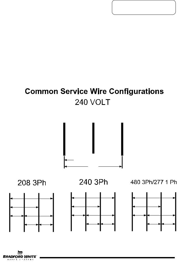
BLACK |
RED |
GREEN |
Ungrounded |
Ungrounded |
Grounding |
240 

 120
120 
120
Neutral |
A |
B |
C |
|
120 |
|
|
120 |
|
|
|
120 |
|
|
208 |
|
208 |
|
208 |
RED BLACK RED
Neutral |
A |
|
B |
C |
Neutral |
A |
|
B |
C |
|
|
120 |
|
|
|
|
277 |
|
|
120 |
|
|
|
277 |
|
|
|
||
120 |
|
|
240 |
|
277 |
|
|
480 |
|
|
|
240 |
240 |
|
|
|
480 |
480 |
|
|
RED |
BLACK |
RED |
|
RED |
BLACK |
RED |
||
Page 3
3

GENERAL INFORMATION
Full Load Amperes-(Phase 1/Phase 3)
Input Kw |
208V |
240V |
277V |
380V |
415V |
480V |
6 |
28.8/16.6 |
25/14.4 |
21.6 |
10 |
8.3 |
12.5/7.2 |
9 |
43.2/25 |
37.5/21.6 |
32.4 |
14 |
12.5 |
18.7/10.8 |
12 |
57.6/33.3 |
50/28.9 |
43.3 |
19 |
16.7 |
25/14.4 |
13.5 |
64.9/37.5 |
56.2/32.5 |
48.7 |
21 |
18.8 |
28.1/16.2 |
15 |
72.1/37.5 |
62.5/36.1 |
54.1 |
23 |
20.9 |
31.2/18 |
18 |
86.5/50 |
75/43.4 |
64 |
28 |
25 |
37.5/21.6 |
Surface Mounted Thermostats
E32 series medium duty commercial water heaters use only surface mounted thermostats. Surface mounted thermostats are mounted into a bracket which holds the thermostat against the side of the tank. Surface mounted thermostats respond to tank surface temperatures to sense a call for heat, set point temperature settings and high limit (ECO) activation. It is import that the entire back surface of the thermostat is in full contact or flush with the tank. An improperly mounted thermostat will lead to improper heater operation.
Manual |
Surface Mount |
|
ECO (high limit) |
||
Combination Thermostat/ |
||
Reset button |
||
ECO (high limit) |
||
|
||
|
89T Series |
|
Temperature |
|
|
control Dial |
|
Direct Immersion “Screw-in” Type Heating Element
1-½ Hex |
|
Terminal Block |
Screw-in Flange |
|
|
|
|
Zinc Plated Copper or
Incoloy Sheath
|
|
|
|
0642 |
4500W 240V |
RC02404524 |
||
|
|
|
|
|||||
|
|
|
|
|||||
|
|
|
|
|||||
|
|
|
|
|
|
|
|
|
Terminal Block |
|
Element Rating Ink Stamped |
Screw |
|
on side of Terminal Block. |
|
|
Page 4
4

SEQUENCE OF OPERATION
E32 series medium duty, field convertible commercial electric water heaters are designed to operate using single phase or three phase service connections. One size fits all Internal fusing is factory installed for all units. When field conversions are required, no fuse change is necessary. Three surface mounted thermostats operating independently are used to control a corresponding heating element.
Sequence of Operation. |
|
Fuse Block |
|
|
|
1 Single phase line voltage is applied |
1 |
|
across terminals L1 and L2 of terminal |
|
|
block. Or Three phase line voltage is |
|
|
applied to terminals L1 through L3 of |
|
|
terminal block. Line voltage continues |
|
|
through terminal block and fuse blocks |
|
|
and connects to thermostats at |
|
|
terminals L1 & L3. |
Terminal Block |
|
|
|
|
2 ECO (high limit) in thermostat is closed, |
2 |
Thermostat closed |
3 |
so there is line voltage present at |
|
|
|
|
at terminal T2 |
|
|
terminal L4 of thermostats and to one |
|
ECO Closed |
|
side of each element. |
|
|
3 |
Water in tank is cold, so all thermostats |
|
|
are closed at terminal T2 (calling For |
Power to one |
|
heat). This completes the circuit and |
side of element |
|
allows current to flow through heating |
|
|
element. |
|
|
|
4 |
4 |
As each thermostat is satisfied, |
Thermostat open |
at terminal T2 |
||
|
it opens at terminal T2 interrupting |
|
|
current flow through the respective |
|
|
element. The system is now in stand-by |
|
|
mode, waiting for the next call for heat. |
|
Page 5
5

FIELD CONVERSION FOR:
KW, Voltage and Phase
The E32 series medium duty commercial electric water heaters are field convertible. This allows Qualified Service Providers the ability to convert wattage, voltage and phase using a factory supplied conversion kit as required per the installation. Underwriters Laboratories Inc. recognizes this procedure as herein presented and no deviation from these instructions are allowed.
KW Conversion
All E32 series medium duty commercial water heaters are factory wired to the maximum electrical duty for which they have been designed. Therefore, internal electrical components satisfy the maximum voltage and maximum electrical current conditions.
These instructions do not allow for a modification that adds or deletes the number of heating elements originally supplied with the heater; therefore such a modification must not be attempted.
Special factory prepared “Conversion Kits” must be used for these conversions. These kits contain the heating elements, element gaskets and product labeling overlays related to the newly created electrical parameters.
18 KW heaters suitable for operation with 208vac cannot be created by conversion since there are no “kits” established for this electrical system. These heaters can be obtained by ordering directly from the factory.
Conversion Kit Available
Total |
Element |
|
Required |
|
---------- Kit Part Numbers ---------- |
||||
Heater KW |
Wattage |
208 volts |
240 volts |
480 volts |
6 |
2000 |
265-43942-13 |
265-43942-07 |
265-43942-01 |
9 |
3000 |
265-43942-14 |
265-43942-08 |
265-43942-02 |
12 |
4000 |
265-43942-15 |
265-43942-09 |
265-43942-03 |
13.5 |
4500 |
265-43942-16 |
265-43942-10 |
265-43942-04 |
15 |
5000 |
265-43942-17 |
265-43942-11 |
265-43942-05 |
18 |
6000 |
265-43942-18* |
265-43942-12 |
265-43942-06 |
*265-43942-18 will require control box replacement (included in kit).
Following the heating element removal and replacement instruction on page 16, remove elements and replace with elements from appropriate kit listed above.
The heaters rating plate will need to be modified because the conversion altered the electrical characteristics of the heater. This rating plate is placed on every Commercial Electric water heater produced by Bradford White Corporation. Element kits above contain rating plate label overlays related to the newly created electrical parameters. Follow the instruction on page 8 For placement of overlays.
Voltage Conversion
1.Voltage conversion is accomplished by replacing the existing elements with elements that are rated at the required voltage.
2.To accomplish this conversion refer to the above procedure for KW Conversion ---- Element Changes.
Control Box Conversion
1.Open front panel of control box installed on water heater and disconnect the (6) load wires from fuse blocks.
2.Remove (4) screws joining control box to water heater and remove control box.
NOTICE
Control box conversion is ONLY required when converting water heater to 18kw 208v (Kit# 265-43942-18)
3.Install new control box onto the water heater by feeding the wires through the back of the control box and reinstall (4) mounting screws.
4.Reconnect wires to new fuse blocks. Be certain to match wire colors to Line side of fuse blocks.


 CAUTION
Use caution to not damage any of the wire insulation when removing control box.
Page 6
6
 Loading...