


POWER VENTED GAS WATER HEATER
A Spanish language version of these instructions is available by contacting the company listed on the rating plate.
La version espanola de estas instrucciones se puede obtener al escribirle a la fabrica cuyo nombre aparece en la placa de especificaciones.
INSTALLATION AND OPERATING
INSTRUCTION MANUAL
WARNING: If the information in these instructions is not followed exactly, a fire or explosion may result causing property damage, personal injury, or death.
FOR YOUR SAFETY
Do not store or use gasoline or other flammable, combustible, or corrosive vapors and liquids in the vicinity of this or any other appliance.
WHAT TO DO IF YOU SMELL GAS
•Do not try to light any appliance.
•Do not touch any electrical switch; do not use any phone in your building.
•Immediately call your gas supplier from a neighbor’s phone. Follow the gas supplier's instructions.
•If you cannot reach your gas supplier, call the fire department.
Installation and service must be performed by a qualified installer, service agency or the gas supplier.
For your family’s comfort, safety and convenience we recommend this water heater be installed and serviced by a plumbing professional.
238-45917-00A REV 3/06

CONGRATULATIONS!
You have just purchased one of the finest water heaters on the market today!
This installation, operation and instruction manual will explain in detail the installation and maintenance of your new Power Vented Gas Water Heater. We strongly recommend that you contact a plumbing professional for the installation of this water heater.
We require that you carefully read this manual, as well as the enclosed warranty, and refer to it when questions arise. If you have any specific questions concerning your warranty, please consult the plumbing professional from whom your water heater was purchased. For your records we recommend that you write the model, serial number and installation date of your water heater in the maintenance section in the back of this manual.
This manual should be kept with the water heater.
2
TABLE OF CONTENTS |
|
|
page |
GENERAL INFORMATION................................................................. |
4 |
INSTALLATION.................................................................................. |
5 |
Locating The Water Heater......................................................... |
5 |
Minimum Clearances .................................................................. |
8 |
Venting......................................................................................... |
8 |
Specifications for |
|
48 Gal (181.6 L) |
|
65 Gal (246.0 L) |
|
75 Gal (283.9 L)................................................................ |
11 |
Specifications for |
|
40 Gal (151.4 L) |
|
50 Gal (189.2 L)................................................................ |
17 |
Vent pipe preparation and joining ............................................. |
23 |
Combustion Air Supply .............................................................. |
25 |
Water Connections...................................................................... |
27 |
Gas Connections......................................................................... |
30 |
Electrical Connections................................................................ |
31 |
Wiring Diagram...................................................................... |
32 |
GENERAL OPERATION .................................................................... |
33 |
Lighting and Shutdown Instructions......................................... |
34 |
Thermostat Adjustment .............................................................. |
35 |
Burner Flame Check ................................................................... |
36 |
MAINTENANCE.................................................................................. |
37 |
TROUBLESHOOTING........................................................................ |
40 |
PARTS LIST DRAWING..................................................................... |
42 |
PARTS LIST ....................................................................................... |
42 |
INSTALLATION INSTRUCTIONS FOR POTABLE WATER AND |
|
SPACE HEATING............................................................................... |
43 |
NOTES................................................................................................ |
44 |
3
GENERAL INFORMATION
This gas-fired water heater’s design is certified by CSA International under the
American National Standard Z21.10.1 and CSA 4.1-M, most current editions at the time of manufacture.
This water heater must be installed in accordance with local codes or, in the absence of local codes, the National Fuel Gas Code, ANSI Z223.1-Latest Edition) and/or in Canada CAN/CGA B149 Installation Codes (Latest Editions). The warranty for this water heater is in effect only when the water heater is installed, adjusted, and operated in accordance with these Installation and Operating Instructions. The manufacturer will not be held liable for any damage resulting from alteration and/or failure to comply with these instructions.
This water heater is not design certified for installation in a mobile home. Such an installation may create a hazardous condition and will nullify the warranty.
 CAUTION
Incorrect operation of this appliance may create a hazard to life and property and will nullify the warranty.
Do not use this appliance if any external part to the tank has been submerged in water. You should contact a qualified service technician to inspect the appliance and to replace any part of the control system including the combination gas control which has been submerged in water.


 DANGER
Do not store or use gasoline or other flammable, combustible, or corrosive vapors and liquids in the vicinity of this or any other appliance.
IMPORTANT
Before proceeding, please inspect the water heater and its components for possible damage. DO NOT install any water heater with damaged components. If damage is evident then please contact the supplier where the water heater was purchased or the manufacturer listed on the rating plate for replacement parts.
Make sure that you check the rating plate and combination gas control on the water heater to be certain that the type of gas being supplied corresponds with the marking on the rating plate and combination gas control.
4

General Information continued-
A sacrificial anode is used to extend tank life. The removal of this anode, for any reason, will nullify the warranty. In areas where water is unusually active, an odor may occur at the hot water faucet due to a reaction between the sacrificial anode and the impurities in the water. If this should happen, an alternative anode may be purchased from the supplier that installed this water heater. This will minimize the odor while protecting the tank. Additionally, the water heater should be flushed with appropriate dissolvers to eliminate any bacteria.
INSTALLATION
Locating The Water Heater
 WARNING
Water heaters are heat producing appliances. To avoid damage or injury, do not store materials against the water heater or vent-air intake system. Use proper care to avoid unnecessary contact (especially by children) with the water heater and vent-air intake components. UNDER NO CIRCUMSTANCES
MUST FLAMMABLE MATERIALS, SUCH AS GASOLINE OR PAINT THINNER BE USED OR STORED IN THE VICINITY OF THIS WATER HEATER, VENT-AIR INTAKE SYSTEM OR IN ANY LOCATION FROM WHICH FUMES COULD REACH THE WATER HEATER OR VENT-AIR INTAKE SYSTEM.
DO NOT install the water heater in any location where gasoline or flammable vapors are likely to be present.
Water Heaters in residential garages must be installed so that all burner(s) and burner ignition device(s) are located not less than 18 inches (46 cm) above the floor and must be located or protected to avoid physical damage. For other installations refer to local codes. In the absence of local codes, the water heater must be installed in compliance with the National Fuel Gas Code, ANSI Z223.1 - (Latest Edition) and/or in Canada, CAN/CGA B149 Installation Codes (Latest Editions).
The location of this water heater is of the utmost importance. Before installing this water heater, read the installation section of these instructions. After reading these installation and operating instructions, select a location for the water heater where the floor is level and is easily accessible to gas and water supply lines. DO NOT locate the water heater where water lines could be subjected to freezing temperatures. Make sure the cold water pipes are not located directly above the gas control so that condensate during humid weather does not drip on the controls.
5

Installation (Locating The Water Heater) continued-
Water heater corrosion and component failure can be caused by the heating and breakdown of airborne chemical vapors. Examples of some typical compounds that are potentially corrosive are: spray can propellants, cleaning solvents, refrigerator and air conditioning refrigerants, swimming pool chemicals, calcium and sodium chloride, waxes and process chemicals. These materials are corrosive at very low concentration levels with little or no odor to reveal their presence. NOTE: DAMAGE TO THE WATER HEATER CAUSED
BY EXPOSURE TO CORROSIVE VAPORS IS NOT COVERED BY THE WARRANTY. DO NOT OPERATE THE WATER HEATER IF EXPOSURE HAS OR WILL OCCUR. DO NOT STORE ANY POTENTIALLY CORROSIVE COMPOUNDS IN THE VICINITY OF THE WATER HEATER.
 WARNING
Liquefied petroleum gases/propane gas are heavier than air and will remain at floor level if there is a leak. Basements, crawl spaces, closets, and areas below ground level will serve as pockets for accumulation of leaking gas. Before lighting, smell all around the appliance area for gas. Be sure to smell next to the floor.
IF YOU SMELL GAS:
•Do not try to light any appliance.
•Do not touch any electric switch; do not use any telephone in your building.
•Immediately call your gas supplier from a neighbor’s telephone. Follow the gas supplier’s instructions.
•If you cannot reach your gas supplier, call the fire department.
DO NOT OPERATE APPLIANCE UNTIL THE LEAKAGE IS CORRECTED!
6

Installation (Locating The Water Heater) continued-
 WARNING
DO NOT ATTEMPT TO LIGHT ANY GAS APPLIANCE IF YOU ARE NOT CERTAIN OF THE FOLLOWING:
•Liquefied petroleum gases/propane gas and natural gas have an odorant added by the gas supplier that aids in the detection of the gas.
•Most people recognize this odor as a “sulfur” or “rotten egg” smell.
•Other conditions, such as “odorant fade” can cause the odorant to diminish in intensity, or ”fade”, and not be as readily detectable.
•If you have a diminished sense of smell, or are in any way unsure of the presence of gas, immediately contact your gas supplier from a neighbor’s telephone.
•Gas detectors are available. Contact your gas supplier, or plumbing professional, for more information.
The water heater must be located close enough to the outside wall to keep the venting distance within the maximum distance described in the installation instructions. Read the venting section in this installation instruction manual before locating the water heater.
This water heater must be located in an area where leakage of the tank or water line connections and the combination temperature and pressure relief valve will not result in damage to the area adjacent to the water heater or to lower floors of the structure. When such locations cannot be avoided, a suitable drain pan adequately piped for proper drainage must be installed under the water heater. The pan must not restrict combustion air flow. The drain pan must be no greater than 1-½ inches (3.8 cm) deep and have a minimum length and width of at least four (4) inches (10.2 cm) measured from the jacket of the water heater. The drain pan, as described above, can be purchased from your plumbing professional. The drain pan must be piped to an adequate drain. The piping must be at least 3/4 inch (1.9 cm) in diameter and pitched for proper drainage.
It is recommended that a minimum clearance of four (4) inches (10.2 cm) be provided on the side of the water heater for servicing and maintenance of the combination temperature and pressure relief valve.
This water heater MUST be installed indoors out of the wind and weather.
Note: For California installation this water heater must be braced, anchored, or strapped to avoid falling or moving during an earthquake. See instructions for correct installation procedures. Instructions may be obtained from California Office of the State Architect, 400 P Street, Sacramento, CA 95814.
7

Installation (Minimum Clearances) continued-
Minimum Clearances
 WARNING
Failure to adhere to these installation and operating instructions may create a hazard to life and property and will nullify the warranty.
This installation must allow access to the front of the water heater and adequate clearance must be provided for servicing and operating this water heater. The water heater may be installed on either a combustible or noncombustible floor. If the water heater is to be installed directly on carpeting, it must be installed on top of a metal or wood panel extending beyond the full width and depth of the appliance by at least three (3) inches (7.6 cm) in any direction or, if the appliance is to be installed in an alcove or closet, the entire floor must be covered by the panel. The minimum clearances to combustibles for this water heater are: zero (0) inch (0 cm) from the sides and rear, five (5) inches (12.7 cm) from the front of the jacket, zero (0) inch (0 cm) from the vent connector and fifteen (15) inches (38.1 cm) from the jacket top.
Venting
This venting section is divided into two parts. Part I will cover venting specifications for 48 Gal (181.6 L), 65 Gal (246.0 L), and 75 Gal (283.9 L) models. Part II will cover venting specifications for 40 Gal (151.4 L) and 50 gal (189.2 L) models. Refer to the rating plate located on the water heater for correct model identification.
Figure 1 - Vent Terminal Clearances
8

Venting continued-
|
|
Canadian |
US Installations2 |
|
|
Installations1 |
|
|
|
|
|
A= |
Clearance above grade, veranda, |
12 inches (30 |
12 inches |
|
porch, deck or balcony |
cm) |
(30 cm) |
B= |
Clearance to window or door that may |
12 inches (30 |
4 feet (1.2 m) below or |
|
be opened |
cm) |
to the side of opening; |
|
|
|
12 inches (30 cm) above |
|
|
|
opening |
C= |
Clearance to permanently closed |
*b |
*b |
|
window |
|
|
D= |
Vertical clearance to ventilated soffit |
*b |
*b |
|
located above the terminal within a |
|
|
|
horizontal distance of 2 feet (61 cm) |
|
|
|
from the center line of the terminal |
|
|
E= |
Clearance to unventilated soffit |
*b |
*b |
|
|
|
|
F= |
Clearance to outside corner |
*b |
*b |
|
|
|
|
G= |
Clearance to inside corner |
36 inches |
36 inches |
|
|
(91 cm)*a |
(91 cm)*a |
H= |
Clearance to each side of center line |
3 feet (91 cm) |
*b |
|
extended above meter/regulator |
within a height |
|
|
assembly |
15 feet (4.6 m) |
|
|
|
above the |
|
|
|
meter/regulator |
|
|
|
assembly |
|
I= |
Clearance to service regulator vent |
36 inches |
*b |
|
outlet or oil tank vent |
(91 cm) |
|
J= |
Clearance to non-mechanical air |
12 inches (30 |
4 feet (1.2m) below or to |
|
supply inlet to building or the |
cm) |
side of opening; 12 |
|
combustion air inlet to any other |
|
inches (30 cm) above |
|
appliance |
|
opening. |
K= |
Clearance to a mechanical air supply |
6 feet |
3 feet (91 cm) above if |
|
inlet |
(1.83 m) |
within 10 feet |
|
|
|
horizontally |
L= |
Clearance above paved sidewalk or |
7 feet |
7 feet |
|
paved driveway located on public |
(2.13 m)† |
(2.13 m)† |
|
property |
|
|
M= |
Clearance under a veranda, porch, |
12 inches (30 |
*b |
|
deck, or balcony |
cm) ‡ |
|
1 In accordance with the current CAN/CGA-B149 Installation Codes.
2 In accordance with the current ANSI Z223.1-(Latest edition)/NFPA 54 National Fuel Gas Code.
† A vent shall not terminate directly above a sidewalk or paved driveway that is located between two singlefamily dwellings and serves both dwellings.
‡ Permitted only if a veranda, porch, deck or balcony is fully open on a minimum of two sides beneath the floor.
*a) A minimum clearance value determined by testing in accordance with section 2.20.
*b) “Clearance in accordance with local installation codes and the requirements of the gas supplier”.
The vent system must terminate so that proper clearances are maintained as cited in local codes or the latest edition of the National Fuel Gas Code, ANSI Z223.1.73.4e and 7.8a, b as follows:
1.Do not terminate near soffit vents or crawl space or other area where condensate or vapor could create a nuisance or hazard or cause property damage.
2.Do not terminate the exhaust vent terminal where condensate or vapor could cause damage or could be detrimental to the operation of regulators, relief valves, or other equipment.
3.Do not terminate the exhaust vent terminal over public area or walkways where condensate or vapor can cause nuisance or hazard.
4.The vent shall terminate a minimum of 12” (25.4 cm) above expected snowfall level to prevent blockage of vent termination.
9
Venting continued-
Vent pipes serving power vented appliances are classified by building codes as “vent connectors”. Required clearances from combustible materials must be provided in accordance with information in this manual under LOCATION OF WATER HEATER and CLEARANCES, and with National Fuel Gas Code and local codes.
Venting System Condensation
Condensate formation does not occur in all installations of power vented water heaters, but should be protected against on installations where condensation can form in the venting system.
Formation of condensation in the venting system of Power Vented water heaters is dependent upon installation conditions including, but not limited to:
ambient temperature and humidity of installation location; ambient temperature and humidity of venting space; vent distance and slope;
and product usage.
In order to effectively control condensate from adversely affecting the mechanical components of the water heater several methods may be employed:
1.For horizontal installations the vent pipe can be installed with a downward slope (not less than 1/8" (3 cm)) and away from the blower.
2.In order to prevent condensate from draining back into the blower (vertical or horizontal runs), an optional condensate kit is available as a service part (Condensate kit, p/n 238-45875-00). A factory supplied exhaust adapter with drain outlet mounts directly to the blower outlet and is secured with two hose clamps, one to the blower and the other to the vent pipe. Plastic tubing is provided to drain any accumulated condensate away from the water heater and to a suitable drain. The kit comes complete with instructions for proper installation.
10
Venting (Part I) continued-
Part I - Venting Specifications for: 48 Gallon (181.6 L)
65 Gallon (246.0 L)
75 Gallon (283.9 L)
NOTE: Properly sized PVC, CPVC, or ABS pipe must be used.
This water heater is a power vented appliance and is designed to vent its products of combustion through 3” (7.6 cm) or 4” (10.2 cm) diameter Schedule 40 (solid or cellular core) vent pipe to the outdoors. This water heater may be either vented horizontally through the wall or vertically through the roof. Use a 3” (7.6 cm) to 4” (10.2 cm) reducer to connect to the vent outlet when using 4” (10.2 cm) vent pipe. Apply the proper cement at the joint locations. Table 1 lists the maximum vent lengths for this water heater using 3” (7.6 cm) vent pipe. If possible, locate the water heater so that the venting length and number of elbows are kept to the minimum distance necessary to reach the outside. If the installation requires venting lengths that exceed the lengths listed for 3” (7.6 cm) vent pipe in Table 1, then use 4” (10.2 cm) vent pipe for the vent connector. Table 2 lists the venting distances allowed with 4” (10.2 cm) diameter vent pipe. When venting with 4” (10.2 cm) vent pipe, use a 4” (10.2 cm) to 3” (7.6 cm) reducer to exit through the building wall with 3” (7.6 cm) vent pipe. Use the 3” (7.6 cm) vent terminal supplied with the water heater to terminate on the outside of the building. If the length of 3” (7.6 cm) vent pipe needed to go through the wall is greater than 14” (35.5 cm), use 4” (10.2 cm) to go through the wall and reduce to 3” (7.6 cm) vent pipe immediately after exiting the outside wall. Refer to the venting illustrations on the following pages. Make sure the vent pipe terminal elbow fitting is at least 1” (2.5 cm) away from the edge of the wall.
TABLE 1 - VENT CONNECTOR LENGTHS
FOR 3” (7.6 cm) DIAMETER VENT PIPE
Terminating |
# of |
Maximum straight |
|
Minimum |
|
|
Elbows |
Length ft (m) |
|
straight |
|
|
|
48, 65 gal. |
75 gal. |
Length ft (m) |
|
Through the Wall |
1 |
55 (16.8) |
45 (13.7) |
2 |
(.6) |
Through the Wall |
2 |
50 (15.2) |
40 (12.2) |
2 |
(.6) |
Through the Wall |
3 |
45 (13.7) |
35 (10.7) |
2 |
(.6) |
Through the Wall |
4 |
40 (12.2) |
30 (9.1) |
2 |
(.6) |
Through the Roof |
0 |
60 (18.3) |
50 (15.2) |
7 |
(2.1) |
Through the Roof |
1 |
55 (16.8) |
45 (13.7) |
7 |
(2.1) |
Through the Roof |
2 |
50 (15.2) |
40 (12.2) |
7 |
(2.1) |
Through the Roof |
3 |
45 (13.7) |
35 (10.7) |
7 |
(2.1) |
11
Venting (Part I) continued-
TABLE 2 -VENT CONNECTOR LENGTHS |
|
|
|||
FOR 4” (10.2 cm) DIAMETER VENT PIPE |
|
|
|||
Terminating |
# of 90° |
Maximum straight |
|
Min |
|
|
Elbows (excl. |
Length ft (m) |
straight |
||
|
vent term.) |
48, 65 gal. |
75 gal. |
Length |
|
|
|
|
|
ft (m) |
|
Through the Wall |
1 |
85 (25.9) |
75 (22.9) |
10 |
(3.1) |
Through the Wall |
2 |
80 (24.4) |
70 (21.3) |
10 |
(3.1) |
Through the Wall |
3 |
75 (22.9) |
65 (19.8) |
10 |
(3.1) |
Through the Wall |
4 |
70 (21.3) |
60 (18.3) |
10 |
(3.1) |
Through the Wall |
5 |
65 (19.8) |
55 (16.7) |
10 |
(3.1) |
Through the Roof |
0 |
90 (27.4) |
80 (24.4) |
15 |
(4.6) |
Through the Roof |
1 |
85 (25.9) |
75 (22.9) |
15 |
(4.6) |
Through the Roof |
2 |
80 (24.4) |
70 (21.3) |
15 |
(4.6) |
Through the Roof |
3 |
75 (22.9) |
65 (19.8) |
15 |
(4.6) |
Through the Roof |
4 |
70 (21.3) |
60 (18.3) |
15 |
(4.6) |
NOTE: When using 4” (10.2 cm) vent pipe, use a 4” (10.1 cm) to 3” (7.6 cm) reducer and exit the building wall with 3” (7.6 cm) vent pipe using the 3” (7.6 cm) 90° vent terminal supplied. Two 45° elbows are equivalent to one 90° elbow.
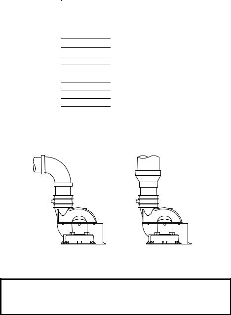
CONNECTION TO 3” (7.6 CM) |
CONNECTION TO A 3” (7.6 CM) TO |
VENT PIPE |
4” (10.2 CM) REDUCER |
Figure 2
IMPORTANT
All of the Venting connections must be leak checked with a soap and water solution upon initial start up of the water heater. Any leaks must be repaired before continuing operation of the water heater.
12
Venting (Part I) continued-
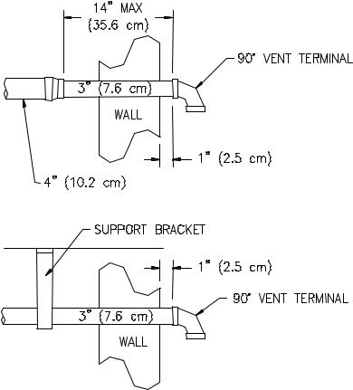
THROUGH THE WALL VENTING: (HORIZONTAL VENTING)
Cut a 3 1/2 in. (8.9 cm) diameter hole in the wall at the point where the vent connector is going to pass through the wall. Use the proper cement to secure the 90° vent terminal provided with the water heater to the vent connector. The distance between the edge of the 90° vent terminal and the exterior wall (see Figure 3) must be 1 in. (2.5 cm). Use the proper cement and assembly procedures to secure the vent connector joints between the terminal and the blower outlet. Provide support brackets for every 5 feet (1.5m) of horizontal vent.
Figure 3
13
Venting (Part I) continued-
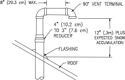
THROUGH THE ROOF VENTING: (VERTICAL VENTING)
Cut the necessary holes through the roof and ceiling and install the vent connector as shown in Figure 4. Make sure that the installation meets the local codes and/or The National Fuel Gas Code ANSI Z223.1 (Latest Edition) or CGA/CAN B149 Installation Code (latest edition).
Figure 4
NOTE: For installations requiring both horizontal and vertical runs, the following rule must be followed: Total length of straight pipe (both horizontally and vertically) must not exceed the allowable length listed in the “Through The Wall” section of the table for total number of elbows used.
14
 Loading...