


Tankless Gas Water Heater
SERVICE
MANUAL
Troubleshooting Guide and Instruction for Service
(To be performed ONLY by qualified service providers)
For the Bradford White EverHot®
Exterior Tankless
Gas Water Heater Models:
IGE-199R-10(N,X) IGE-199C-5(N,X)
Manual 45096A |
Save this manual for future reference |

Key to Warning Symbols
Failure to comply with the following instructions may results in serious personal injury or damage to the appliance.
Be careful of possible electric shock. Wiring inside this appliance may potentially be at 120 volts.
Disconnect power supply to unit when carrying out the following service repairs.
Read Fault Diagnosis and Wiring Diagram carefully to avoid incorrect wiring.
Do not disassemble. Parts within can not be exchanged or diagnosed faulty.
Please follow the instructions in the following chapters to ensure safe and appropriate service.
After completing the service and confirming that there are no water or gas leaks or incorrect wiring, test operation of the appliance.
2

TABLE OF CONTENTS |
|
|
Section |
Description |
Page |
- - - |
Glossary of Terms and Symbols..................................................... |
4 |
I ...................... |
General Information........................................................................ |
5 |
|
a. How to Use This Manual. ................................................ |
6 |
|
b. Cut Away illustration. ...................................................... |
7 |
|
c. Schematic illustration. ..................................................... |
8 |
II ..................... |
Specifications. (General)................................................................. |
9 |
|
a. Combustion Specifications.............................................. |
11 |
|
b. Default Dip Switch Settings............................................. |
12 |
III .................... |
Main Components. ......................................................................... |
13 |
IV .................... |
Safety Device Function. .................................................................. |
15 |
V ..................... |
Sequence of Operation................................................................... |
17 |
|
a. Operation Sequence Flow Chart. .................................... |
19 |
|
b. Sequence Timing Chart................................................... |
21 |
VI .................... |
Troubleshooting (error messages).................................................. |
23 |
|
a. Quick Reference Diagnostic Points. ................................ |
25 |
|
b. Wiring Diagram ................................................................ |
27 |
|
c. Troubleshooting Flow Chart. ........................................... |
29 |
|
d. Trouble Shooting Procedure. .......................................... |
34 |
VII ................... |
Gas Pressure Setting Procedure. ................................................... |
44 |
VIII .................. |
Service Procedures......................................................................... |
46 |
IX .................... |
Flushing Procedure for Lime Scale Removal .................................. |
52 |
X ..................... |
Parts Breakdown ............................................................................ |
53 |
Refer to installation and operation manual for the following reference information:
•General Dimensions.
•Piping Recommendations.
•Remote Control Features.
•Water Flow Rates vs Temperature.
3

GLOSSARY OF TERMS AND SYMBOLS
This glossary of terms and symbols is provided to assist you in understanding some of the language used throughout this manual.
dB(A) |
- sound pressure level in decibels, "A" range |
|
DC |
- |
direct current |
AC |
- |
alternating current |
WFCD |
- water flow control device |
|
FB |
- |
feedback information |
Hz |
- |
hertz |
IC |
- |
integrated circuit |
BTU/H |
- British thermal units per hour |
|
PSI |
- Pounds per square inch |
|
LED |
- |
light emitting diode |
GPM |
- |
gallons per minute |
mA |
- |
milliamps |
W.C. |
- inches of water column |
|
mm |
- |
millimeters |
NOx |
- oxides of nitrogen NO & NO2 |
|
OHS |
- |
overheat switch |
PCB |
- |
printed circuit board |
CPU |
- |
central processing unit |
POT |
- |
potentiometer |
rpm |
- |
revolutions per minute |
SV |
- |
solenoid valve |
Ø- diameter
∆°F |
- |
delta T or temperature rise above ambient |
POV |
- |
modulating valve |
TE |
- |
thermal efficiency |
TH |
- |
thermistor |
TIN |
- |
temperature of incoming water |
Tout |
- |
temperature of outgoing water |
4

I - GENERAL INFORMATION
This tankless water heater is a high output, high efficiency appliance, which heats the water continuously as hot water is being drawn for use. Unlike tank type storage water heaters, this water heater does not store hot water. The burner operates whenever there is a demand for hot water and is off when the water flow stops. Hot water is continuously supplied for any length of time required, as long as the specified flow rates are not exceeded. There is no need to set the temperature higher than required for sufficient capacity. The water heater has sufficient capacity to supply several hot water faucets simultaneously. The hot water flow capability will be dependent upon the temperature of the outlet water selected. Operational features of this water heater include:
•This water heaters is designed to be installed outdoors on an outside wall using the supplied wall bracket. No indoor space is needed and the water heater can be mounted at a height convenient for servicing.
•The burners ignite by direct spark ignition within 3 seconds of detecting minimum operational water flow. There is no standing pilot.
•A variable speed combustion air blower forces the combustion air supply into the burner compartment.
•No venting system required. For outdoor installation only.
•An optional recess box is available which allows the water heater to be recessed into an outside wall and conceal the piping behind a cover for a more attractive installation. The box enclosure dimensions are: 40 12⁄ " H x 14 34⁄ " W x 9 12⁄ " D. Contact your supplier to order this optional accessory.
•The burner flame is continuously monitored and modulated to match the heating requirements of the water flow. Temperature and flow sensors continually monitor the water flow and outlet water temperature and adjust the burner and combustion air blower to maintain temperature.
•The included, remote mount Main Control may be conveniently located near the point of use and is adjustable from 96-160°F for residential models or 96-180°F for commercial models. In addition to the Main Control, up to two optional bathroom controls are available on the residential models for setting the temperature in the bathroom fixtures up to 120°F.
•The Remote Main Control also displays fault codes if the water heater malfunctions to assist with servicing the water heater.
•The heat exchanger coil is provided with anti-freeze heaters for cold climate conditions for protection as low as -30°F (-34°C). Drain solenoids should be installed to drain the water heater in the event of a power failure. (See installation instructions)
Tools Required for Troubleshooting
Multifunction Digital Test Meter with needle point test leads. Long reach (12") Magnetic Phillips screw driver (#2 Tip). 3/16 Allen wrench.
Small (pocket size) blade screw driver.
Monometer or Magnehelic inches water column gage.
5
I - GENERAL INFORMATION (cont.)
HOW TO USE THIS MANUAL
It is intended for this manual to be used by qualified service personnel for the primary purpose of troubleshooting analysis and repair of this tankless gas fired water heater. Understanding the basic operation of the "Main Components" and the "Sequence of Operation" sections of this manual will contribute greatly to your success in the troubleshooting analysis of this product.
Sections of this manual reference general information and specifications. The primary focus is trouble shooting analysis and repair. The trouble shooting section consists of the following:
• Error Message Table
Table showing Error Message as displayed on remote control indicating likely fault and remedy.
• Quick Reference Diagnostics Points Table
This guide will identify the specific diagnostic point for each component as well as the correct electrical value for each component.
• Troubleshooting Flow Chart
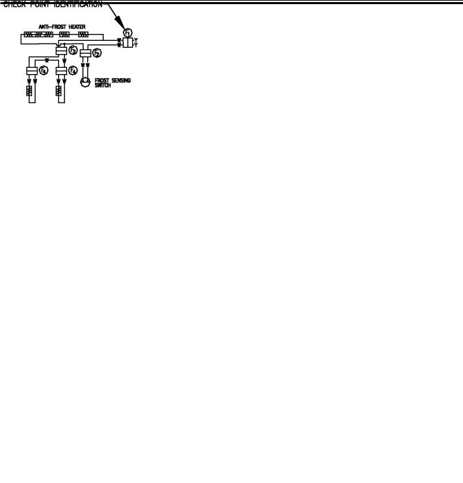
The "Trouble Shooting Flow Chart" identifies fault potentials and directs service to the appropriate diagnostic check points. The check points are identified in the troubleshooting procedure and are shown on the wiring diagram by means of an encircled letter with a subscript number.
Example:
This chart will also refer to a page number to reference a pictorial version of the component analysis as outlined in the "Trouble Shooting Procedure" section of this manual.
• Trouble Shooting Procedure
Pictorial procedure including diagnostic points, electrical values and referral to "Service Procedure" for replacement of faulty components.
• Quick Reference Diagnostics Points Table
Quick reference guide for all diagnostic points.
• Service Procedure
Pictorial procedure for removal and replacement of components.
6
I - GENERAL INFORMATION (cont.)
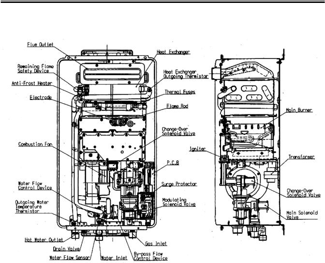
CUT-AWAY ILLUSTRATION
7

I - GENERAL INFORMATION (cont.)
SCHEMATIC ILLUSTRATION
8

II - SPECIFICATIONS – GENERAL
Type of appliance |
Temperature controlled continuous flow gas hot water system |
||
Operation |
With/without remote controls |
|
|
|
|
|
|
Exhaust system |
Direct Vent - Forced combustion |
|
|
|
|
|
|
Model Type |
Residential |
|
Commercial |
Maximum/Minimum |
|
|
|
gas rate (Input Btu's) |
199,000 Btu's – 15,000 Btu's Natural gas |
||
|
199,000 Btu's – 15,000 Btu's Propane Gas |
||
|
|
|
|
Thermal Efficiency |
Natural Gas 84% |
Propane Gas 85% |
|
|
|
|
|
Energy Factor (EF) |
Natural Gas 0.82 |
Propane Gas 0.84 |
|
Capacity (Gallons 1st |
Natural Gas 218 |
Propane Gas 227 |
|
Hour @ 90°F rise) |
|
|
|
|
|
|
|
NOx Emissions (at 3% 02) |
Less than 40 ppm |
|
|
Hot water capacity (50°F rise) |
0.5 to 6.5 GPM's |
|
|
|
|
|
|
Setpoint Temperature |
Factory setting - 120°F |
|
|
(without remote) |
|
|
|
Temperature range |
BC-45-4US 96 - 120°F |
MCC-45-4US 96 - 160°F |
|
with remote keypads connected |
BSC-45-4US 96 - 120°F |
|
|
|
MC-45-4US 96 - 180°F |
|
|
Approved gas type |
Natural or Propane – Ensure unit matches gas supply type. |
||
|
|
|
|
Installation |
Outdoor installation ONLY |
|
|
|
|
|
|
Dimensions |
Height 2358⁄ " |
|
|
|
Width 1334⁄ " |
|
|
|
Depth 878⁄ " |
|
|
Weight |
46 Lbs. |
|
|
Noise levels |
49 dB's |
|
|
|
|
|
|
Connections |
Gas supply |
34⁄ " MNPT |
|
|
Cold water inlet |
34⁄ " MNPT |
|
|
Hot water outlet |
34⁄ " MNPT |
|
Ignition system |
Direct electronic ignition |
|
|
|
|
|
|
Electrical consumption |
Operating |
63 watts |
|
|
Standby |
5.5 watts |
|
|
Anti-frost protection 84 watts |
|
|
|
|
|
|
Water temperature control |
Simulation feedforward and feedback |
||
Water flow control |
Water flow sensor and automatic electro-mechanical water |
||
|
control device |
|
|
|
|
|
|
Recommended Minimum water |
|
|
|
supply pressure |
20 PSI (recommend 50-80 PSI for maximum performance) |
||
Maximum water supply pressure |
150 PSI |
|
|
9

II - SPECIFICATIONS – GENERAL (cont.)
Power Supply |
Appliance – 120 Volts A.C. – 60 Hz. |
|
|
Remote control 12 volt D.C. (Digital) |
|
|
|
|
Safety Devices |
Flame failure - Flame rod |
|
|
|
|
|
Boiling protection - 203˚F |
|
|
Remaining flame (OHS) 194˚F bi-metal switch |
|
|
|
|
|
Fusible link |
|
|
|
|
|
Automatic frost protection |
|
|
- Bimetal sensor & anti-frost heaters |
|
|
|
|
|
Combustion fan rpm check - integrated circuit |
|
|
|
|
|
Over current - Glass fuse (3 amp) |
|
Remote control cable |
Non-polarized two core cable |
|
|
|
|
Clearances from combustibles |
Top of heater |
12" |
|
|
|
|
Front of heater |
24" |
|
Sides of heater |
6" |
|
|
|
|
Back of heater |
0" |
|
|
|
|
Ground |
12" |
|
Installations within RGB-25 Recess Box: Clearances |
|
|
from combustibles to recess box top, bottom, back and |
|
|
sides = 0" |
|
Clearances from Eaves, |
Top of heater |
36" |
Porches, Overhangs |
|
|
|
|
|
10
II - SPECIFICATIONS (cont.)
COMBUSTION SPECIFICATIONS
Item |
Gas Type |
Natural |
Propane |
Gas consumption |
Minimum Btu's |
15,000 |
15,000 |
|
Maximum Btu's |
199,000 |
199,000 |
Injector Diameter |
Upper |
ø.045 (1.15mm) |
ø.029 (.75mm) |
Inches (mm) |
Lower |
ø.070 (1.8mm) |
ø.045 (1.15mm) |
Main Burner |
B3A7-1 (Lean and Rich Bunsen Burner) |
||
Main Damper |
H73-115 (Upper: ø6, Lower: Not Used) |
||
Gas Pressure |
|
|
|
Supply/Manifold |
Minimum Supply |
6" W.C. |
10" W.C. |
|
Maximum Supply |
10.5" W.C. |
13.5" W.C. |
|
Low Fire Manifold |
0.56" W.C. |
0.88" W.C. |
|
High Fire Manifold |
3.4" W.C. |
5.1" W.C. |
11

II - SPECIFICATIONS (cont.)
DIP SWITCH SETTINGS
 DANGER
Do not attempt to adjust dip switch settings from there factory default settings. Doing so will result in damage to unit, property damage, personal injury or death.
Contact Technical Support for information pertaining to dip switch function.
FACTORY DEFAULT SETTING, RESIDENTIAL UNITS
Natural Gas Model |
Propane Gas Models |
||
Dip Switch Settings: |
Dip Switch Settings: |
||
(SW1) |
(SW2) |
(SW1) |
(SW2) |
#1 = Off |
#1 = On |
#1 = Off |
#1 = Off |
#2 = On |
#2 = Off |
#2 = On |
#2 = Off |
#3 = Off |
#3 = Off |
#3 = Off |
#3 = Off |
#4 = Off |
#4 = Off |
#4 = Off |
#4 = Off |
#5 = Off |
|
#5 = Off |
|
#6 = Off |
|
#6 = Off |
|
#7 = Off |
|
#7 = Off |
|
#8 = Off |
|
#8 = Off |
|
FACTORY DEFAULT SETTING, COMMERCIAL UNITS
Natural Gas Models |
Propane Gas Models |
||
Dip Switch Settings: |
Dip Switch Settings: |
||
(SW1) |
(SW2) |
(SW1) |
(SW2) |
#1 = Off |
#1 = On |
#1 = Off |
#1 = Off |
#2 = On |
#2 = Off |
#2 = On |
#2 = Off |
#3 = Off |
#3 = Off |
#3 = Off |
#3 = Off |
#4 = Off |
#4 = On |
#4 = Off |
#4 = On |
#5 = Off |
|
#5 = Off |
|
#6 = Off |
|
#6 = Off |
|
#7 = Off |
|
#7 = Off |
|
#8 = Off |
|
#8 = Off |
|
12
III - MAIN COMPONENTS
1. Mechanical Water Regulator
The unique water regulator mechanism ensures the hot water is maintained with no noticeable change to the desired temperature during use, even if water pressure drops due to another tap being turned on and increasing the demand.
2. Preset Bypass
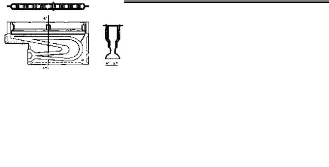
A preset volume of cold water is mixed with water heated in the heat exchanger.
3. Burner
The burner assembly is made up of 16 identical stainless steel Bunsen burners, secured by an aluminized steel framework. An aluminum manifold with 32 integral injectors supplies gas to the burners, and is attached to the front lower cover of the burner box and gas control assembly.
4. Gas Control Valve
The gas control valve uses four solenoids to fully modulate within four different input ranges to respond quickly and accurately to changes in water flow rate. The four ranges are as follows: up to 18% of total btu's (using three burners), up to 33% (using five burners), up to 50% (using eight burners, and up to 100% (using sixteen burners) This increases the flexibility of the regulator/ modulating valve by supplying gas equally to each burners.
13
III - MAIN COMPONENTS (cont.)
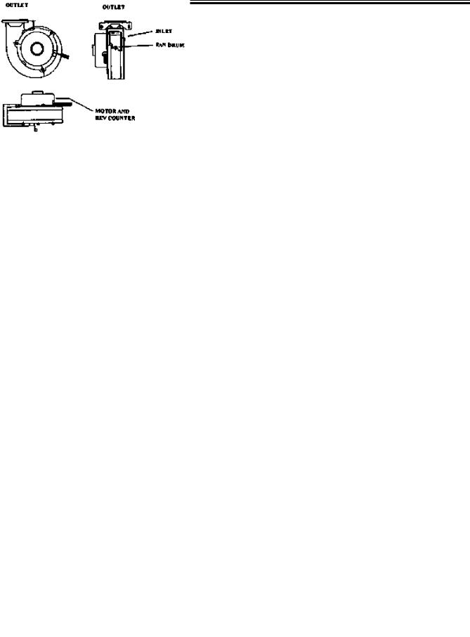
5. Combustion Fan
Air for the combustion is supplied by a centrifugal fan driven by a DC motor. After a pre-purge period of 0.2 seconds, the fan speed is controlled by the PCB to provide the correct volume of air for combustion. The calculation for the fan speed is based upon incoming water temperature, water flow and the temperature selected on the remote controls.
The actual speed of the motor is continuously monitored by a magnetic pulse sensor.
This sensor emits (4) pulses per rotation of the fan. This is the fan feedback or confirmation data processed by the PCB.
The fan speed is constantly correcting to provide optimum combustion conditions. In addition, the fan speed will determine the opening degree of the modulating gas valve. This enables the gas rate to always match the volume of air for combustion, as well as the input required to heat the water.
1. Water Flow Sensor and Water Flow Control device
Water flow is detected by a turbine/magnetic pulse generating device. Water flows through the turbine/magnetic sensor providing information to the PCB by generating a pre-determined number of pulses in proportion to the water flow. These pulses are counted by the PCB – no pulse indicates no water flow. The frequency of the magnetic pulses increases as the water flow increases, this enables the PCB to calculate the exact water flow, and determine the water flow in gallons per minute. As soon as the required water flow is detected, the PCB activates the combustion fan. The combustion fan speed is monitored by a magnetic pulse sensor. The output from this sensor is processed by the PCB which opens the gas modulating valve to a degree proportional to the fan speed.
See above for further details on the combustion fan.
The water flow control consists of a plug and barrel valve which is rotated by a motor to increase or decrease the volume of water passing through the heat exchanger.
Automatic water flow control device
14

IV - SAFETY DEVICE FUNCTION
Flame Failure
Situated to the right of the burner in the front of the combustion chamber, the flame rod monitors the combustion process. This sensor monitors the flame intensity, while the PCB compares this signal to the feed back signal from the combustion fan motor, water flow control, and gas flow through the POV valve. If any one of the feedback signals are incorrect, the unit will shut off, preventing discharge of gas to the burner.
Over Heat Protection Device
Also referred to as an Over Heat Switch. This device is fitted to a bend section at the left side of the heat exchanger. If the flame remains on to the burner after the tap is closed and the water temperature inside the heat exchanger reaches 194° F, a 12 volt DC bi-metal cut-off switch will shut off the gas supply to the solenoids.
No Water
Should the incoming water flow become restricted or stop, the water flow sensor will cease to send a magnetic pulse signal to the PCB, in turn preventing gas to flow into the combustion chamber. If you have restricted flow, first check to ensure the inline water filter is not clogged.
Thermal Fuse (Non-Resettable)
Wrapped around the entire surface of the heat exchanger you will find a thermal fuse. This device activates in the event of excessive heat exchanger temperature or the temperature outside the heat exchanger reaches 264 °F. If the thermal fuse melts, it breaks an electronic circuit which in turn shuts off the power supply to the gas solenoids, deactivating the unit.
Combustion Fan Revolution Check
The combustion fan rpm's are continually monitored by a magnetic pulse generator connected to the PCB. If the fan revolutions deviate from the speed required for complete combustion, a signal is sent to the PCB and the revolutions adjust accordingly. (If not the unit deactivates)
Automatic Frost Protection
When the temperature inside the appliance drops below 37°F , the frost sensing device inside the appliance activates the anti-frost heaters to prevent the water inside the unit from freezing. The antifrost heaters remain ON until the temperature inside the appliance rises to 57°F. There are five (16) watt anti-frost heaters located at various points throughout the main water flow area of the appliance. The unit also incorporates the ability to fire for (3) seconds in the event the anti-frost heaters can not keep the water temperature from dropping below 37°F. This unique feature will heat the water in the lines inside the appliance back up to 57°F. Both of the above features function as long as the unit has power and gas. There is an optional freeze protection system that can be added to the unit's piping. See the auto drain down drawing in the product Owner's manual for instructions on how to install the option freeze protection in the event of a power failure in cold climates.
15

IV - SAFETY DEVICE FUNCTION (cont.)
Over temperature Cut-Off
The temperature of the outgoing hot water is constantly monitored by the water temperature thermistor located near the outlet of the appliance. If the outgoing water temperature reaches 5 °F above the preset temperature, the burner will automatically deactivate. The burner will ignite again when the outgoing hot water temperature falls below the preset temperature.
16

V - SEQUENCE OF OPERATION
The preset temperature is selected at one of the remotes controls (where fitted). Where no remote control is fitted , the default temperature can be set at 108, 120, 130, 140, 150, 160, 170, or 180 °F. To select one of the above temperatures as your default setting, you MUST obtain written permission and training. (Contact your technical service group)
When the unit is first plugged into 120 volts, the PCB assumes an incoming water temperature of 77°F. This prevents the appliance from starting in "High fire" and producing very hot water the first time it is used.
The data used to determine the outgoing water temperature, initially, is incoming water flow and the remote control pre-set temperature.
From the incoming water flow and remote control pre-set temperature data, the CPU is able to determine a suitable gas rate to initiate the appliance operation once a hot water tap opens.
The calculation of temperature rise and water flow is called simulation feed-forward.
The water heater calculates incoming water temperature by subtracting the theoretical temperature rise from the outgoing hot water temperature to establish the correct gas flow.
When a hot water tap is opened, water begins to flow through the water heater. The turbine in the water flow sensor begins to revolve. The revolution speed is proportional to the water flow. A sensor located inside the device relays information in the form of magnetic pulses to the main PCB to determine whether or not water is flowing, and also, the volume of water flowing. When a predetermined water flow is sensed, the ignition sequence begins.
The combustion fan pre-purges the combustion chamber. A rev counter on the combustion fan indicates the fan rpm to the main PCB. When the pre-purge cycle is completed, the PCB controls the fan rpm by varying the DC voltage to the fan motor. This maintains the correct air/gas ratio throughout the time the water heater is in use and ensures proper combustion.
The gas is ignited by direct spark and the flame is sensed by the flame rod. The opening degree of the modulating valve is determined by the combustion fan speed.
The changeover valve directs gas to one side or both sides of the burner. At the point where the changeover valve opens or closes the modulating valve is instantly re-adjusted by the PCB to compensate for the change in the number of burners in use. From the information provided by the water flow sensor and the water temperature thermistor, the PCB determines how much gas is required to heat the water to the temperature selected on the remote control.
The PCB is programmed to provide the maximum volume of water possible at a given temperature rise. As the water flow from the tap is increased, the PCB increases the gas and air flow to the burner.
17

V - SEQUENCE OF OPERATION (cont.)
When the hot water tap is turned off, the water flow sensor stops revolving, and the magnetic pulse ceases, indicating to the PCB that there is no water flowing, in turn the PCB closes the gas valves. The combustion fan continues to operate for 65 seconds. This will provide quicker ignition when the tap is turned on and off in rapid succession, and removes the need for a pre-purge cycle allowing the burner to re-light immediately when a hot water tap is opened again.
18
 Loading...