

Boss GT-1000 Core Owner’s Manual
Owner’s Manual
Getting Ready . . . . . . . . . . . . . . . . . . . . . . . . . . . . . . . . . . . . . . . . . 2
Connecting the Equipment . . . . . . . . . . . . . . . . . . . . . . . . . . . . . . 2
Turning the Power On . . . . . . . . . . . . . . . . . . . . . . . . . . . . . . . . . . . 3
Specify the Type of Amplier You Have Connected . . . . . . 3
Adjusting the Volume . . . . . . . . . . . . . . . . . . . . . . . . . . . . . . . . . . . 3
Using the Tuner . . . . . . . . . . . . . . . . . . . . . . . . . . . . . . . . . . . . . . . . . . 3
Tuner Settings . . . . . . . . . . . . . . . . . . . . . . . . . . . . . . . . . . . . . . . . . . 3
Playing . . . . . . . . . . . . . . . . . . . . . . . . . . . . . . . . . . . . . . . . . . . . . . . . . 4
Selecting a Patch . . . . . . . . . . . . . . . . . . . . . . . . . . . . . . . . . . . . . . . . 4
About the Play Screen . . . . . . . . . . . . . . . . . . . . . . . . . . . . . . . . . . 4
Selecting the Control Mode . . . . . . . . . . . . . . . . . . . . . . . . . . . . . 5
Using the GT-1000CORE with a Bass Guitar . . . . . . . . . . . . . . 5
Editing: Eects . . . . . . . . . . . . . . . . . . . . . . . . . . . . . . . . . . . . . . . . 6
Basic Procedure for Eect Editing . . . . . . . . . . . . . . . . . . . . . . . . 6
Eect Placement . . . . . . . . . . . . . . . . . . . . . . . . . . . . . . . . . . . . . . . . 6
Using STOMPBOX . . . . . . . . . . . . . . . . . . . . . . . . . . . . . . . . . . . . . . . . 7
Editing the STOMPBOX . . . . . . . . . . . . . . . . . . . . . . . . . . . . . . . . . 7
Reading STOMPBOX Settings into a Patch . . . . . . . . . . . . . . . 7
Writing Patch Settings into a STOMPBOX . . . . . . . . . . . . . . . . 8
Saving a Patch . . . . . . . . . . . . . . . . . . . . . . . . . . . . . . . . . . . . . . . . . . . 8
Editing: MENU . . . . . . . . . . . . . . . . . . . . . . . . . . . . . . . . . . . . . . . . . 9
Basic MENU Operations . . . . . . . . . . . . . . . . . . . . . . . . . . . . . . . . . . 9
Assigning Favorite Parameters to [1]–[5] Knobs . . . . . . . . . . 9
Adjusting the Contrast (Brightness) of the Display . . . . . . . 9
Restoring the Factory Default Settings (Factory Reset) . . . 10
Turning O the Auto O Function . . . . . . . . . . . . . . . . . . . . . . . 10
Using the Metronome . . . . . . . . . . . . . . . . . . . . . . . . . . . . . . . . . . 10
Connecting to a Computer . . . . . . . . . . . . . . . . . . . . . . . . . . . 11
Installing the USB Driver . . . . . . . . . . . . . . . . . . . . . . . . . . . . . . . . . 11
Using the GT-1000CORE as an Audio Interface . . . . . . . . . . . 11
Connecting with an External MIDI Device . . . . . . . . . 12
Operations from the GT-1000CORE . . . . . . . . . . . . . . . . . . . . . . 12
Operations from an External MIDI Device . . . . . . . . . . . . . . . . 12
Footswitch and Expression Pedal Settings . . . . . . . . 13
Assigning a Function . . . . . . . . . . . . . . . . . . . . . . . . . . . . . . . . . . . . 13
Making Assignments from the Eect Edit Screen
(Quick Assign)
Connecting External Pedals . . . . . . . . . . . . . . . . . . . . . . . . . . . . . 14
. . . . . . . . . . . . . . . . . . . . . . . . . . . . . . . . . . . . . . . . . . 13
Looper . . . . . . . . . . . . . . . . . . . . . . . . . . . . . . . . . . . . . . . . . . . . . . . . . . 15
Assigning Looper Functions to Switches . . . . . . . . . . . . . . . . . 15
Loop Playback Level Setting . . . . . . . . . . . . . . . . . . . . . . . . . . . . 15
Switch Color . . . . . . . . . . . . . . . . . . . . . . . . . . . . . . . . . . . . . . . . . . . . 15
Main Specications . . . . . . . . . . . . . . . . . . . . . . . . . . . . . . . . . . . 16
USING THE UNIT SAFELY . . . . . . . . . . . . . . . . . . . . . . . . . . . . . 16
IMPORTANT NOTES . . . . . . . . . . . . . . . . . . . . . . . . . . . . . . . . . . . 17
Before using this unit, carefully read “USING THE UNIT SAFELY” and
“IMPORTANT NOTES” (leaet “USING THE UNIT SAFELY” and Owner’s
Manual (p. 16, 17)).After reading, keep the document(s) where it will
be available for immediate reference.
© 2020 Roland Corporation
Owner’s Manual (this document)
Read this rst. It explains the basic things you need to know in
order to use the GT-1000CORE.
PDF Manual (download from the Web)
5 Parameter Guide
This explains all parameters of the GT-1000CORE.
5 Sound List
This is a list of the sounds built into the GT-1000CORE.
5 MIDI Implementation
This is detailed information about MIDI messages.
To obtain the PDF manual
1. Enter the following URL in your computer.
http://www.boss.info/manuals/
I
2. Choose “GT-1000CORE” as the product name.
Getting Ready
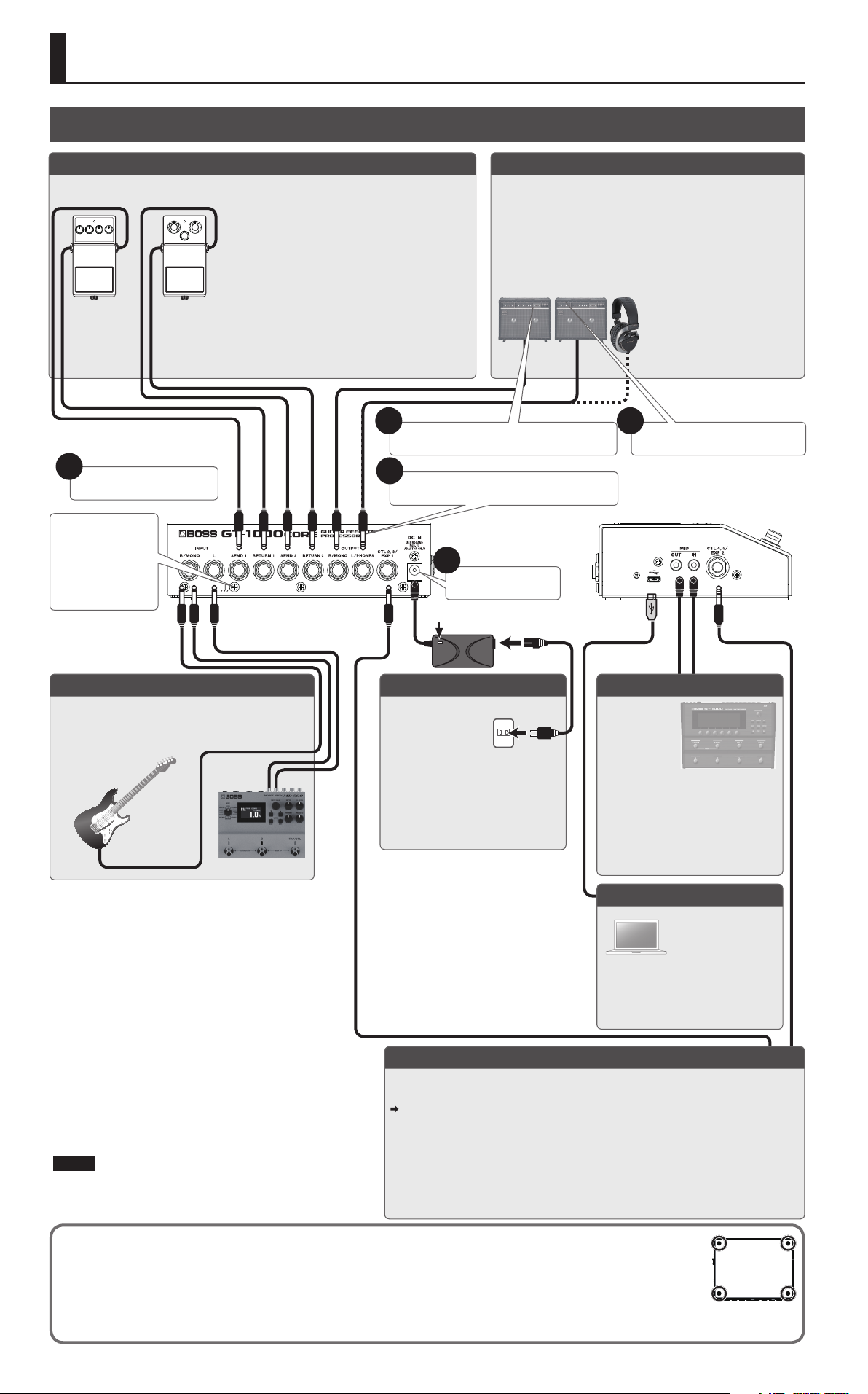
Connecting the Equipment
SEND (1, 2)/RETURN (1, 2) jacks
Connect an external eect processor
here.
3
Connect your guitar, etc.
Ground Terminal
* Connect this
to an external
earth or ground
if necessary.
Rear Panel Side Panel (Left)
You can also use the SEND (1, 2)/RETURN
(1, 2) jacks as SEND (L, R)/RETURN (L, R) jacks
for connecting a stereo eect unit.
You can also use the SEND (1, 2) jacks as
SUB OUT jacks, and use the RETURN jacks as
AUX IN jacks.
For details on the parameter, refer to
“GT-1000CORE Parameter Guide” (PDF).
1
Turn down the volume of the connected device.
2
Connect your equipment to the OUTPUT jack(s).
4
Turning the power on.
OUTPUT jack
Connect these to your guitar amp, mixer, or headphones
(sold separately.
* If using a mono connection, use only the R/MONO jack.
* Connect your headphones to the L/PHONES jack. If you’re
using headphones, don’t connect anything to R/MONO
jack.
* Only the OUTPUT signal is output from the headphones.
The SUB OUT signal is not
output. For details, refer to
“GT-1000CORE Parameter
Guide” (PDF).
5
Turn on the power of the amp(s).
INPUT R/MONO, L jacks
Connect your guitar or the output of another eect
unit.
If you are inputting in mono, use only the R/MONO
jack.
Indicator
DC IN jack
Connect the included AC adaptor
here.
* The DC IN jack
also serves as the
power switch. Power is turned on
whenever a plug is inserted into
the DC IN jack, and is turned o
when the plug is disconnected.
MIDI IN/OUT jacks
Connect an
external MIDI
device here.
(p. 12)
* Use a
TRS/MIDI
connecting cable (sold separately:
BMIDI-5-35) to connect an
external MIDI device.
* Do not connect an audio
device here. Doing so will cause
malfunctions.
USB COMPUTER port
Use a USB cable
to connect to a
computer and
exchange audio/MIDI
data between the
GT-1000CORE and
the computer (p. 11).
* To prevent malfunction and equipment failure, always turn
down the volume, and turn o all the units before making any
connections.
* Before turning the unit on/o, always be sure to turn the volume
down. Even with the volume turned down, you might hear some
sound when switching the unit on/o. However, this is normal
and does not indicate a malfunction.
NOTE
While the display indicates “SAVING...,” data is being
CTL2, 3/EXP 1 jack, CTL4, 5/EXP 2 jack
You can control various parameters by connecting an expression pedal (EV-30,
Roland EV-5: sold separately) or a footswitch (FS-5U, FS-6, FS-7: sold separately).
For details on the settings, refer to “Footswitch and Expression Pedal Settings”
(p. 13).
* You can use the CTL4, 5/EXP 2 jack to switch the channels of your guitar amp. For
details, refer to “GT-1000CORE Parameter Guide” (PDF).
* Use only the specied expression pedal. By connecting any other expression
pedals, you risk causing malfunction and/or damage to the unit.
saved. Do not turn o the power during this time.
Attaching the Rubber Feet
You can attach the rubber feet (included) if necessary.
Attach them in the locations shown in the illustration.
* Using the unit without rubber feet may damage the oor.
* When turning the unit over, be careful so as to protect the buttons and knobs from damage. Also, handle the unit carefully; do not drop it.
2
Getting Ready
In this manual, the order of the MENU operations is written as
follows.
<Example>
Press the [MENU] button.
Use the [3] knob to select “IN/OUT SETTING.”
Use the [1] knob to select “INPUT.”
?
Choose [MENU] 0 “IN/OUT SE TTING” 0 “INPUT.”
Turning the Power On
Turn the power on in the order of steps 1–5.
To turn the power o, reverse the order.
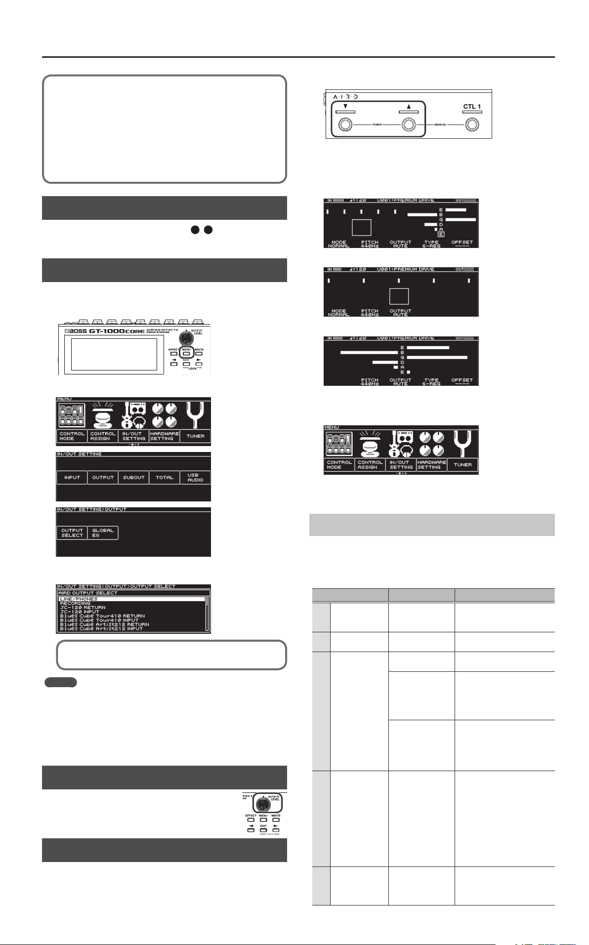
Specify the Type of Amplier You Have Connected
1. Choose [MENU]
“OUTPUT SELECT.”
0
“IN/OUT SETTING” 0 “OUTPUT” 0
1. Press the [
The tuner screen appears.
You can use the PAGE [K] [J] buttons to switch the tuner
display.
Monophonic/polyphonic display
Monophonic display
Polyphonic display
I
] (H) switch.
The menu screen appears.
2. Turn knob [SELECT] to select the type of amp.
For details on the amp types, refer to the “GT-1000CORE
Parameter Guide” (PDF).
MEMO
If you are using the AIRD PREAMP of the GT-1000CORE,
we recommend that in order to take full advantage of its
characteristics, you connect to an input that is not aected
by a preamp, such as the RETURN jack, rather than using the
guitar input jack that is aected by the preamp of the guitar
amp.
Adjusting the Volume
Use [OUTPUT LEVEL] knob to adjust the overall
volume of the GT-1000CORE.
Using the Tuner
The GT-1000CORE is equipped with a conventional monophonic
tuner which lets you tune your instrument one string at a time,
and a polyphonic tuner which lets you play and tune all of your
open strings simultaneously.
You can also start the tuner as follows.
1. Choose [MENU]
“TUNER” is located in the rst page of the menu.
Use the PAGE [K] [J] buttons to access the rst page.
0
“TUNER.”
Tuner Settings
To make tuner settings, use knobs [1]–[6] located below the
display.
Tuner settings
Parameter Value Explanation
MODE
[1]
(TUNER MODE)
[2] Pitch
[3] OUTPUT
[4] TYPE
[5] OFFSET -5–-1, ----
NORMAL, STREAM
435–445 Hz
(default: 440 Hz)
MUTE
BYPASS
THRU
6-REG
(6-REGULAR),
6-DROP D,
7-REG
(7-REGULAR),
7-DROP A,
4-B REG
(4-B REGULAR),
5-B REG
(5-B REGULAR)
Species the meter display
method for the monophonic
tuner.
Species the reference pitch.
Sound will not be output
while tuning.
While tuning, the sound of
the guitar being input to the
GT-1000CORE will be output
without change. All eects
will be o.
Allows you to tune while
hearing the current eect
sound.
* Only for monophonic
tuner.
Selects the type of tuning
for the polyphonic tuner.
Adjusts the reference pitch
of the polyphonic tuner in
semitone units relative to
standard tuning.
3

Playing
Selecting a Patch
A combination of eects and their settings is called a “patch.”
User patch (U001–U250)
Can be overwritten
Patch
Preset patch (P001–P250)
Cannot be overwritten, however, you can write
a Preset patch into the User area, modify the
settings to your needs and store your modied
version in the User area.
Show eect conguration
Icons shown in the play screen
Areas which icons are displayed
1. Use the [
I
] switch or [H] switch to select a patch.
Patch Number
Patch name
MEMO
You can also change patches by turning knob [SELECT] below
the display.
About the Play Screen
The screen that appears after you turn on the power is called the
“Play screen.”
The following four types of play screen are provided; use the
PAGE [K] [J] buttons to switch between the types of display.
Indication Explanation
Indicates the input level.
Indicates the output level.
Indicates the return level.
Indicates the send level.
Indicates the amount of compression when the
compressor is operating.
Indicates the BPM.
,
Blinks in time with the BPM.
Indicates the page to which you navigate using the
PAGE [K] [J] buttons (edit screen).
MEMO
You can change the parameters that are adjusted by knobs [1]–
[5] when the play screen is shown.
For details, refer to the “Assigning Favorite Parameters to [1]–[5]
Knobs” (p. 9).
Large patch number
Large patch name
Show functions assigned to switches of this unit
MEMO
When the screen at left
is shown, you can press
the PAGE [K] [J] buttons
simultaneously to edit the
functions that are assigned to
the switches of the unit.
Use the [SELECT] knob to
select the switch that you
want to edit, and then press
the [SELECT] knob to select
the function.
To return to the previous
screen, press the PAGE [K] [J]
buttons simultaneously once
again.
4
Playing
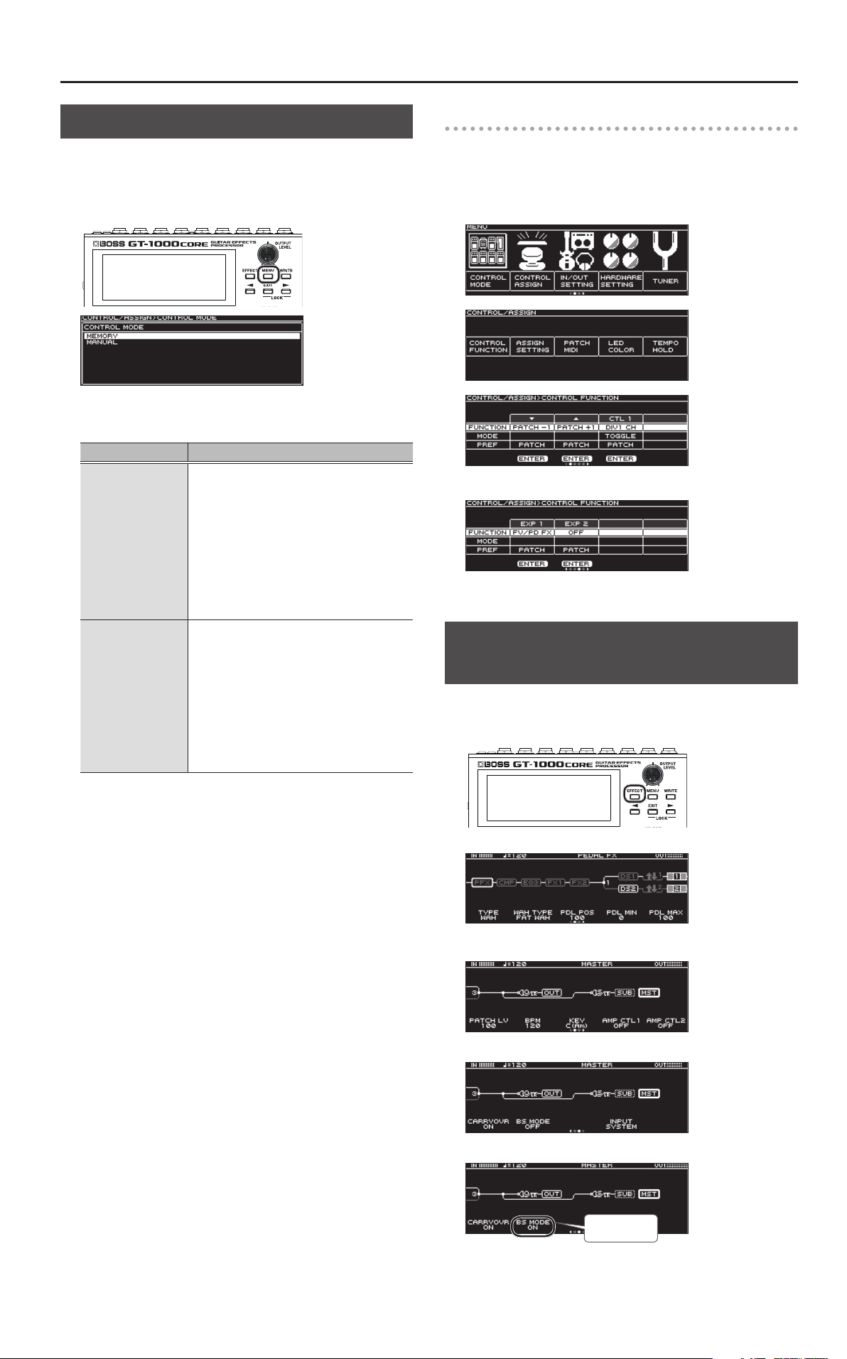
Selecting the Control Mode
The control mode setting lets you choose how you want to
operate the eects.
1. Choose [MENU]
2. Turn knob [SELECT] to select the control mode.
Parameter Explanation
MEMORY
(Memory mode)
MANUAL
(Manual mode)
0
“CONTROL MODE.”
This mode lets you recall and use the patches
that are saved in the unit.
Use the [I] switch and [H] switch to switch
patches.
* Press the [I] switch and [H] switch
simultaneously to start the tuner.
* Press the [H] switch and [CTL 1] switch
simultaneously to select manual mode.
* Even in memory mode, you can select
functions other than patch recall.
This mode lets you use the [I] switch and
[H] switch to operate the functions that are
assigned to them by each patch or by the
settings for the entire system.
When you select manual mode, a portion of
the PLAY screen changes.
* Press the [I] switch and [H] switch
simultaneously to start the tuner.
* Press the [H] switch and [CTL 1] switch
simultaneously to select memory mode.
Assigning the switches in manual mode
In manual mode, the functions that are assigned to [I], [H], and
[CTL1] switches can be changed as follows.
1. Choose [MENU]
FUNCTION.”
2. Use the PAGE [
0
“CONTROL ASSIGN” 0 “CONTROL
K
] [J] buttons to move to the last page.
3. Use knobs [1]–[2] to select parameters or edit the values.
Using the GT-1000CORE with a Bass Guitar
If you’re using a bass guitar, turn bass mode on.
1. Press the [EFFECT] button.
The edit screen (eect chain) appears.
2. Turn knob [SELECT] to select “MST.”
3. Use the PAGE [
K
] [J] buttons to move to the last page.
4. Turn knob [2] (BS MODE) to select “ON.”
Turn ON
5
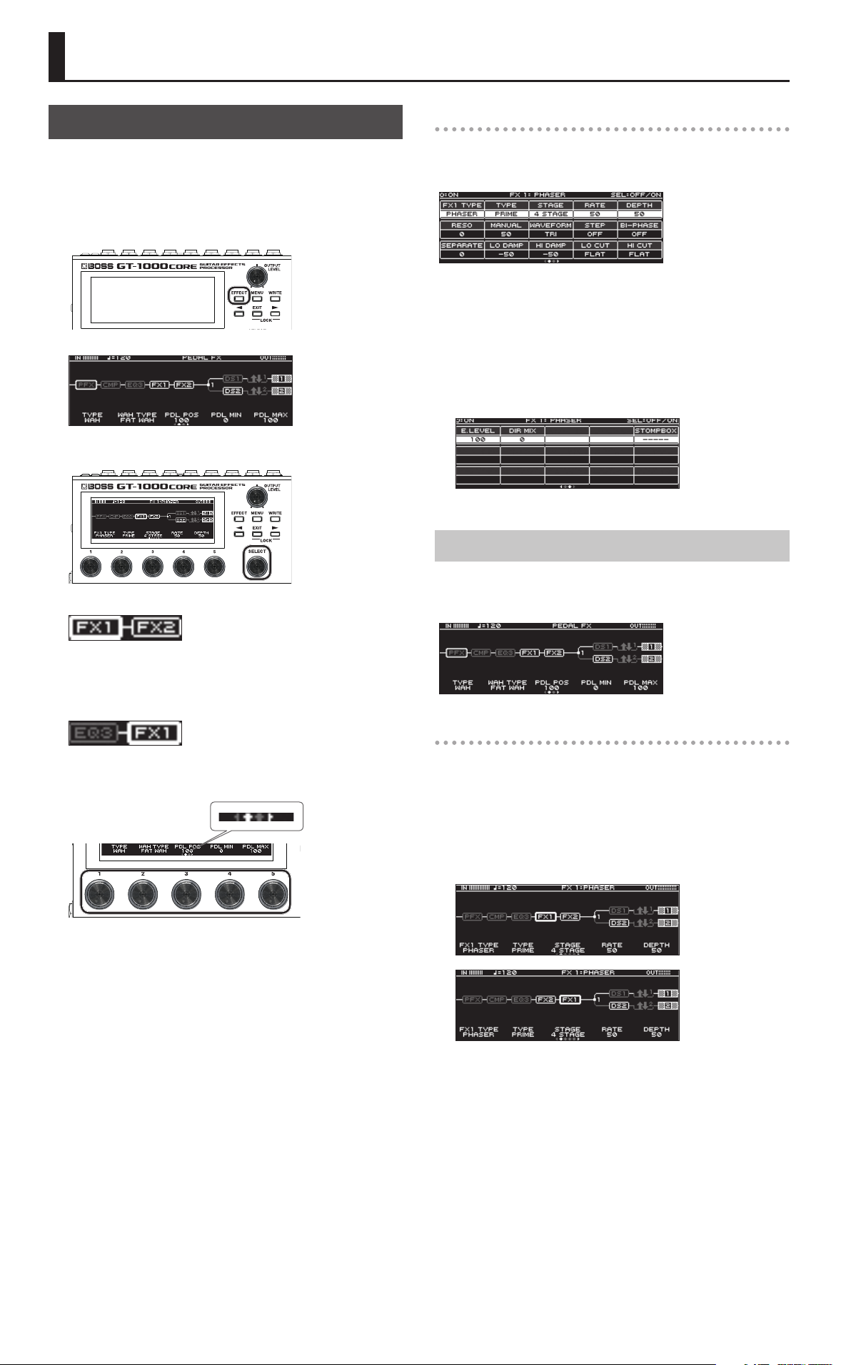
Editing: Eects
Basic Procedure for Eect Editing
The edit screens show the block conguration (eect chain) of
all eects provided by the GT-1000CORE, as well as the output
and send/return. You can edit from this eect chain display by
selecting the block that you want to edit.
1. Press the [EFFECT] button.
The edit screen (eect chain) appears.
2. Turn knob [SELECT] to select the block that you want to edit.
Editing while viewing all parameters
From the edit screen, you can long-press knob [SELECT] to see
a list of all parameters of the selected block. You can edit the
parameters from this list.
1. Turn the [SELECT] knob to select the item that you want to
set.
Turning the knob will move the selected item vertically.
2. Turn knobs [1]–[6] to edit the value of the parameters
shown in the screen.
Use the PAGE [K] [J] buttons to switch between lists of
parameters.
The selected block is enclosed by a thick frame.
* By pressing knob [SELECT ] you can turn the selected eect
on/o. Eects that are o are shown in gray. When the eect is
turned on, it is shown in white.
O On
3. Use knobs [1]–[5] to adjust the parameters that are shown
below the screen.
Use the PAGE [K] [J] buttons to switch between the
parameters that you want to edit. The current page is
indicated in the lower center of the screen.
Eect Placement
By moving blocks such as eects, output, and send/return, you
can freely change the order in which the eects are placed, or
arrange them in parallel.
Changing the placement of eects etc.
1. Press the [EFFECT] button.
The eect chain is shown.
2. Use knob [SELECT] to select the block that you want to
move.
3. While pressing knob [SELECT], turn it left or right.
The selected block moves left or right.
* To change a value in larger steps, turn a knob while pressing it.
* The number of parameters and pages diers depending on
the eect.
6
 Loading...