


Panaray® Sound System
502 Array, Bass Box and Controller
©2006 Bose Corporation |
Service Manual |
Reference Number 170310-SM Rev. 03
Electronic Copy Only
CONTENTS |
|
Contents ......................................................................................................................................... |
2-3 |
Safety Information............................................................................................................................. |
4 |
Warranty ............................................................................................................................................. |
4 |
Specifications ................................................................................................................................ |
5-7 |
502®A Array Specifications ............................................................................................................... |
5 |
502B Bass Module Specifications ................................................................................................... |
6 |
502C Controller Specifications .................................................................................................... |
6-7 |
Electrostatic Discharge Sensitive (ESDS) Device Handling ......................................................... |
8 |
Parts Lists and Exploded Views ...................................................................................................... |
8 |
Parts List Notes ................................................................................................................................. |
9 |
Packaging Part List, 502A Array (see Figure 1) ............................................................................ |
10 |
Figure 1. 502A Array Packaging View ............................................................................................ |
10 |
Packaging Part List, 502B Bass Box (see Figure 2) .................................................................... |
11 |
Figure 2. 502B Bass Box Packaging Exploded View ..................................................................... |
11 |
Packaging Part List, 502C Controller (see Figure 3) ................................................................... |
12 |
Figure 3. 502C Controller Packaging View ..................................................................................... |
12 |
Main Part List, 502A Array (see Figure 4) ..................................................................................... |
13 |
Figure 4. 502A Array Exploded View .............................................................................................. |
14 |
Main Part List, 502B Bass Box (see Figures 5 and 6) ................................................................. |
15 |
Figure 5. 502B Bass Box Exploded View ....................................................................................... |
16 |
Figure 6. 502B Access Panel and Connector Views ...................................................................... |
17 |
Main Part List, 502C Controller (chassis with removable front panel) (see Figure 7) ............. |
18 |
Figure 7. 502C Controller Exploded View (removable front panel version) .................................... |
19 |
Main Part List, 502C Controller (one-piece chassis) (see Figure 8)........................................... |
20 |
Figure 8. 502C Controller Exploded View (one-piece chassis version) .......................................... |
20 |
Electrical Part Lists ................................................................................................................... |
21-30 |
502C Controller Main PCB Assembly ...................................................................................... |
21-30 |
Disassembly Procedures ............................................................................................................... |
31 |
502A Array Procedures ............................................................................................................. |
31-34 |
Figure 9. 502A Array Exploded View .............................................................................................. |
32 |
Figure 10. 502A Array Wiring Diagram ........................................................................................... |
33 |
502B Bass Module Procedures ............................................................................................... |
34-35 |
502C Controller Disassembly Procedures ............................................................................. |
35-36 |
Figure 11. 502B Bass Module Exploded View ................................................................................ |
37 |
Figure 12. 502B Bass Module Connector and Access Panel ......................................................... |
38 |
Figure 13. 502B Bass Module Wiring Diagrams ............................................................................ |
39 |
Figure 14. 502C Controller Exploded View (removable front panel version) ................................. |
40 |
Figure 15. 502C Controller Exploded View (one-piece chassis version) ........................................ |
40 |
Test Procedures .............................................................................................................................. |
41 |
502A Array Test Procedures ........................................................................................................... |
41 |
Figure 16. XLR input pin assignment ............................................................................................ |
41 |
502B Bass Module Test Procedures ....................................................................................... |
41-42 |
502C Controller Test Procedures ............................................................................................ |
42-44 |
Figure 17. Unbalanced Connections .............................................................................................. |
45 |
Figure 18. 502C Controller Back Panel (Barrier Strip Version Shown)........................................... |
45 |
Accessory Kit Part Lists ........................................................................................................... |
46-51 |
502A PSA-5 Stand Adapter Parts List (see Figure 19) ................................................................. |
46 |
Figure 19. PSA-5 Stand Adapter Kit ............................................................................................... |
46 |
502A CSB-5A Suspension Bracket Kit Parts List (see Figure 20) .............................................. |
47 |
Figure 20. CSB-5A Suspension Bracket Kit ................................................................................... |
47 |
2
|
CONTENTS |
|
502B CSB-5B Suspension Bracket Kit Parts List (see Figure 21) .............................................. |
48 |
|
Figure 21. CSB-5B Suspension Bracket Kit ................................................................................... |
48 |
|
502A WBP-5 Bi-Pivot Bracket Kit Parts List (see Figure 22) ....................................................... |
49 |
|
Figure 22. WBP-5 Bi-Pivot Bracket Kit ........................................................................................... |
49 |
|
502A WCB-5 U-Bracket Kit Parts List (see Figure 23) ................................................................. |
50 |
|
Figure 23. WCB-5 U-Bracket Kit .................................................................................................... |
50 |
|
502A CVT-5 Transformer Assembly Kit Parts List (Figure 24) .................................................... |
51 |
|
Figure 24. CVT-5 Exploded View and Packaging ........................................................................... |
51 |
|
Figure 25. CVT-5 Schematic .......................................................................................................... |
52 |
|
Theory of Operation .................................................................................................................. |
53-55 |
|
502C Controller ............................................................................................................................... |
53 |
|
1. |
Differential Input Stage ............................................................................................................... |
53 |
2. |
Equalizer for High Frequency Outputs ..................................................................................... |
53 |
3. |
Output mode switch, Low frequency level control, and Normal/Sum mode stage .............. |
53 |
4. |
Equalizer for Low Frequency Outputs ...................................................................................... |
53 |
5. Mode switch ................................................................................................................................ |
53 |
|
6. |
Output stage ................................................................................................................................ |
54 |
7. |
Power Supply .............................................................................................................................. |
54 |
8. |
Turn On/Off Muting Circuit ......................................................................................................... |
54 |
9. |
Troubleshooting Tips ............................................................................................................ |
54-55 |
502C Controller EQ Curves ...................................................................................................... |
56-61 |
|
Figure 26. Low Frequency EQ ........................................................................................................ |
56 |
|
Figure 27. Low Frequency EQ ........................................................................................................ |
56 |
|
Figure 28. Low Frequency EQ ........................................................................................................ |
57 |
|
Figure 29. Low Frequency EQ ........................................................................................................ |
57 |
|
Figure 30. High Frequency EQ ....................................................................................................... |
58 |
|
Figure 31. High Frequency EQ ....................................................................................................... |
58 |
|
Figure 32. High Frequency EQ ....................................................................................................... |
59 |
|
Figure 33. High Frequency EQ ....................................................................................................... |
59 |
|
Figure 34. High Frequency EQ ....................................................................................................... |
60 |
|
Figure 35. High Frequency EQ ....................................................................................................... |
60 |
|
Figure 36. High Frequency EQ ....................................................................................................... |
61 |
|
Figure 37. 502C Controller Block Diagram ..................................................................................... |
62 |
|
Service Manual Revision History................................................................................................... |
63 |
|
3

SAFETY INFORMATION
1.Parts that have special safety characteristics are identified by the 

 symbol on schematics or by special notes on the parts list. Use only replacement parts that have critical characteristics recommended by the manufacturer.
2.Make leakage current or resistance measurements to determine that exposed parts are acceptably insulated from the supply circuit before returning the unit to the customer.
Use the following checks to perform these measurements:
A.Leakage Current Hot Check - With the unit completely reassembled, plug the AC line cord directly into a 120V AC outlet. (Do not use an isolation transformer during this test.) Use a leakage current tester or a metering system that complies with American National Standards Institute (ANSI) C101.1 "Leakage Current for Appliances" and Underwriters Laboratories (UL) UL6500 / UL60065 / IEC 60065 paragraph 9.1.1. With the unit AC switch first in the ON position and then in OFF position, measure from a known earth ground (metal waterpipe, conduit, etc.) to all exposed metal parts of the unit (antennas, handle bracket, metal cabinet, screwheads, metallic overlays, control shafts, etc.), especially any exposed metal parts that offer an electrical return path to the chassis. Any current measured must not exceed 0.5 milliamp. Reverse the unit power cord plug in the outlet and repeat test. ANY MEASUREMENTS NOT WITHIN THE LIMITS SPECIFIED HEREIN INDICATE A POTENTIAL SHOCK HAZARD THAT MUST BE ELIMINATED BEFORE RETURNING THE UNIT TO THE CUSTOMER.
B.Insulation Resistance Test Cold Check - (1) Unplug the power supply and connect a jumper wire between the two prongs of the plug. (2) Turn on the power switch of the unit. (3) Measure the resistance with an ohmmeter between the jumpered AC plug and each exposed metallic cabinet part on the unit. When testing 3 wire products, the resistance measured to the product enclosure should be between 2 and infinite MOhms. Also, the resistance measured to exposed input/output connectors should be between 4 and infinite MOhms. When testing 2 wire products, the resistance measured to exposed input/output connectors should be between 4 and infinite MOhms. If it is not within the limits specified, there is the possibility of a shock hazard, and the unit must be repaired and rechecked before it is returned to the customer.
CAUTION: The Bose® Panaray® 502® Sound System contains no user-serviceable parts. To prevent warranty infractions, refer servicing to warranty service stations or factory service.
PROPRIETARY INFORMATION
THIS DOCUMENT CONTAINS PROPRIETARY INFORMATION OF
BOSE CORPORATION WHICH IS BEING FURNISHED ONLY FOR
THE PURPOSE OF SERVICING THE IDENTIFIED BOSE PRODUCT
BY AN AUTHORIZED BOSE SERVICE CENTER OR OWNER OF
THE BOSE PRODUCT, AND SHALL NOT BE REPRODUCED OR
USED FOR ANY OTHER PURPOSE.
WARRANTY
The Bose Panaray 502C Controller is covered by a limited 1-year warranty. The Panaray 502A array speaker and Panaray 502B bass module are covered by a 5-year limited warranty.
4
SPECIFICATIONS
502A Array Specifications |
|
Dimensions: |
23.5"H x 5.75"W x 6.73"D |
|
(59.7x14.6x17.1 cm) |
Weight: |
15 lbs. (6.8 kg.) |
Transducer Complement: |
5 - 4.5 " (11.4 cm) drivers |
Enclosure Material: |
High-impact polystyrene |
Nominal Impedance: |
8 Ohms, 6.4 Ohms minimum |
Sensitivity: |
90 dB SPL (1W, 1m, 130 Hz-15 kHz) |
Maximum Acoustic Output: |
112 dB SPL average, 121 dB SPL peak |
Frequency Range: |
130 Hz - 15 kHz |
Port Tuning Frequency: |
135 Hz |
Amplifier Power (Recommended): |
150 - 600 watts continuous into 8 Ohms |
Long-term power handling: |
150 watts continuous |
Beamwidth: |
120° horizontal, 70° vertical |
Input Connections: |
Parallel wired barrier strip (US/Can.) |
|
Parallel wired XLR (Euro/Aus/UK/Japan) |
Fusing: |
4 ampere AGC (Buss) or 3AG (Littlefuse) |
5
SPECIFICATIONS
502B Bass Module Specifications
Dimensions: |
|
31.0"H x 14.0"W x 15.5"D |
|
|
(78.7x 35.6x 39.4 cm) |
Weight: |
|
80 lbs. (36.4 kg.) |
Transducer Complement: |
1 - 12" woofer (high power) |
|
Enclosure Material: |
3/4" resin-core, vinyl wrapped |
|
Port: |
|
High-impact polystyrene |
Nominal Impedance: |
8 Ohms, 6.4 Ohms minimum |
|
Sensitivity: |
|
90 dB SPL (1W, 1m, 55 Hz-150 Hz) |
Maximum Acoustic Output: |
115 dB SPL average, 122 dB SPL peak |
|
Frequency Range: |
50 Hz - 150 Hz |
|
Power Handling: |
|
450 watts continuous |
Amplifier Power (Recommended): |
450 - 1200 watts continuous into 8 Ohms |
|
Input Connections: |
2 parallel wired barrier strip (US/Can) |
|
|
|
2 parallel wired XLR (Euro/Aus/UK/Japan) |
|
|
2 parallel wired Speakon® connectors |
Fusing: |
|
7 ampere AGC (Buss) or 3AG (Littlefuse) |
502C Controller Specifications |
|
|
Dimensions: |
120V/Barrier Strip |
1.75"Hx19.0"Wx8.75"D (4.4x48.3x22.2cm) |
|
220-240V/XLR |
1.75"Hx19.0"Wx8.0"D (4.4x48.3x20.3cm) |
Weight: |
|
5.5 lbs. (2.5 kg.) |
Chassis material: |
|
16 gauge steel with painted/zinc coated finish |
Cover plate material: |
Brushed aluminum,painted |
|
Input Connections: |
Balanced barrier strip (US/Can) |
|
|
|
Balanced XLR (Euro/Aus/UK/Japan) |
Output Connections: |
Balanced barrier strip (US/Can) |
|
|
|
Balanced High frequency & Low frequency |
|
|
XLR (Euro/Aus/UK/Japan) |
6
SPECIFICATIONS
502C Controller Specifications (continued)
Input Impedance: |
Balanced input, -10 dB level - 14k Ohms |
|
|
Balanced input, +4 dB level - 6k Ohms |
|
|
Unbalanced input (+ input), -10 dB level: 12k Ohms |
|
|
Unbalanced input (+ input), +4 dB level: 4k Ohms |
|
Output Impedance: |
100 |
Ohms nominal |
Input Level: |
-10 dB or +4dB, selectable |
|
Output Level: |
8.0 Vrms maximum into 600 Ohms |
|
Low Frequency (LF) Output Mode: |
Sum or normal |
|
LF Output Level: |
-18 dB to +3 dB, variable |
|
Crossover Frequency: |
140 |
Hz (Bi-amp), Roll-off slope: -18dB/octave |
THD: |
Midrange distortion of HF output: - 0.1% at 5V, 600 Hz |
|
|
Low frequency distortion of LF out: - 0.1 % at 5V, 80 Hz |
|
Output Noise: |
Bi-amp mode, HF outputs - 90µV |
|
|
Bi-amp mode, LF outputs - 40µV |
|
|
Passive mode, - 90µV |
|
Offset: |
All channels - 15mV |
|
Power Requirements: |
120 |
VAC,50/60 Hz, 12 watts (US/Can) |
|
230 |
VAC,50/60 Hz, 12 watts (Euro) |
|
100 |
VAC,50/60 Hz, 12 watts (Japan) |
|
240 |
VAC,50/60 Hz, 12 watts (Aus/UK) |
7
ELECTROSTATIC DISCHARGE SENSITIVE (ESDS)
DEVICE HANDLING
This unit contains ESDS devices. We recommend the following precautions when repairing, replacing or transporting ESDS devices:
•Perform work at an electrically grounded work station.
•Wear wrist straps that connect to the station or heel straps that connect to conductive floor mats.
•Avoid touching the leads or contacts of ESDS devices or PC boards even if properly grounded. Handle boards by the edges only.
•Transport or store ESDS devices in ESD protective bags, bins, or totes. Do not insert unprotected devices into materials such as plastic, polystyrene foam, clear plastic bags, bubble wrap or plastic trays.
PARTS LISTS AND EXPLODED VIEWS
The following section contains parts lists and exploded views for the Panaray® sound system. The parts lists are broken down as follows:
-502®A Array Parts List and Exploded View
-502A Packaging Parts List and Exploded View
-502B Bass Box Parts List and Exploded View
-502B Packaging Parts List and Exploded View
-502C Controller Main Assembly Parts List and Exploded View
-502C Packaging Parts List and Exploded View
-502C Electrical Parts List
-Accessory Kits Parts Lists and Exploded Views
NOTE: The notes section for the entire parts list is contained on page 8.
CAUTION: Use only accessory kit parts that are specified by Bose® Corporation in this service manual. Substitute parts may not have the same safety characteristicsas the original parts.
8

PARTS LIST NOTES
1. This part is not normally available from Customer Service. Approval from the Field Service Manager is required before ordering.
2.This part splits into 2 pieces. Each piece fits onto a corner of the bass box.
3.Current European units should contain 2 owner's manuals: the original version, P/N 143585, and the German version of the owner's manual, P/N 171941. Future production units (except in North America) will contain owner's manuals in 5 languages (German, French, Italian, Spanish and English).
4.This illustration is typical of the internal layout of the 502® except as follows: (1) Barrier strip connectors are used in the US/Canada version only. XLR connectors are used on all non-US versions, and (2) The nut connected to the line cord is used on the US/Canada, UK and Australian units only.
5. 

 This part is critical for safety purposes. Failure to use a substitute replacement with the same safety characteristics as the recommended replacement part might create shock, fire and/ or other hazards.
6. Refer to the 502C Electrical Parts List for components located on the PCB assembly.
7. This part is not illustrated.
8. These screws hold regulators U13 and U14 to the heatsink.
9. Early production runs of the 502C have 4 screws (instead of 2) that secure the cover to the chassis.
10. Early production runs of the 502C with XLR connectors have 12 screws (instead of 6) that secure the connectors to the chassis.
11. Early production runs of the 502C have 6 screws (instead of 4) that secure the front plate to the cover and chassis.
12. Early production runs of the 502C with XLR connectors have 5 screws (instead of 2) that secure the PCB to the chassis.
13. The line cord assembly consists of the following items:
(1)Line Cord-P/N 147428 (US/Canada), P/N 147430 (Euro), P/N 147429 (Japan), P/N 149025 (UK), P/N 149026 (Aus.),
(2)Strain Relief Bushing - P/N 144010 (US/Canada/UK/Aus), P/N 144011 (Euro/Japan),
(3)Connector Housing - P/N143964, and
(4)Connector Pin - P/N 143992. These parts are all safety controlled components. See Note 5.
9

PACKAGING PART LIST
502A Array (see Figure 1)
Item |
Description |
XLR and Barrier |
*Speakon |
Qty |
Note |
Number |
|
Version Product |
Version |
|
|
|
|
code 003840, |
Product |
|
|
|
|
004931, 004932 |
code |
|
|
|
|
and 004933 |
040170 and |
|
|
|
|
|
040171 |
|
|
1 |
Literature Kit-Panaray® |
149271 |
- |
1 |
|
|
which consists of: |
|
|
|
|
A |
Polybag |
103351 |
103351 |
1 |
|
B |
Owner's Manual |
143585 |
292721 |
|
|
C |
Registration Card |
122157 |
- |
|
|
D |
Warranty Service List |
122766 |
- |
|
|
E |
Envelope |
122785 |
- |
|
|
2 |
Packing, Foam |
143573 |
172321 |
2 |
|
3 |
Polybag |
106595 |
- |
1 |
|
4 |
Carton, 502A |
143572 |
172541 |
1 |
|
*Product code 040170 (gray) and 040171 (white) are the RoHS compliant version of the 502A. Only RoHS compliant parts listed in the above chart can be used in the 502A with product code 040170 and 040171.1
Figure 1. 502A Array Packaging View
10
PACKAGING PART LIST
502B Bass Box (see Figure 2)
Item |
Description |
XLR and Barrier |
*Speakon® |
Qty |
Note |
Number |
|
Version |
Version PC |
|
|
|
|
PC 003841, |
040090 and |
|
|
|
|
019769, 004934, |
040091 |
|
|
|
|
004935, 004936, |
|
|
|
|
|
007698 |
|
|
|
1 |
Literature Kit-Panaray® |
149271 |
- |
1 |
|
|
Which consists of: |
|
|
|
|
A |
Polybag |
103351 |
103351 |
1 |
|
B |
Owners Manual |
143585 |
292040 |
1 |
|
C |
Registration Card |
122157 |
- |
1 |
|
D |
Warranty Service List |
122766 |
- |
1 |
|
E |
Envelope |
122785 |
- |
1 |
|
2 |
Packing End Cap, EPS |
139955 |
- |
4 |
2 |
|
(XLR and Barrier versions) |
|
|
|
|
|
Packing End Cap, EP |
- |
258886 |
|
|
|
(Speakon version) |
|
|
|
|
3 |
Polybag |
119320 |
119320 |
1 |
|
4 |
Carton, 502B |
143558 |
258887 |
1 |
|
*Product code 040090 (black) and 040091 (white) are a RoHS compliant version of the 502B. Only RoHS compliant parts listed in the above chart can be used in the
502B with product code 040090 and 040091.
1
Figure 2. 502B Bass Box Packaging Exploded View
11

PACKAGING PART LIST
502C Controller (see Figure 3)
Item |
Description |
Part Number |
Qty. |
Note |
Number |
|
|
|
|
1 |
Crease Sheet, Die Cut |
149823 |
1 |
|
2 |
Literature Kit, Panaray®, Consists of: |
149271 |
1 |
|
A |
Poly bag |
103351 |
1 |
|
B |
Owner's Manual |
143585 |
1 |
|
|
Owner's Manual (German language) |
171941 |
1 |
3 |
C |
Card, Registration |
122157 |
1 |
|
D |
List, Warranty Service |
122766 |
1 |
|
E |
Envelope |
122785 |
1 |
|
3 |
Poly bag |
110892 |
1 |
|
4 |
Insert |
148354 |
1 |
|
5 |
Carton, 502C |
148353 |
1 |
|
Figure 3. 502C Controller Packaging View
12

MAIN PART LIST
502A Array (see Figure 4)
Item |
Description |
Part Number |
Qty. |
Note |
Number |
|
|
|
|
1 |
Grille, Pro Gray |
142342-01 |
1 |
|
|
Grille, Arctic White |
142342-02 |
|
|
2 |
Insert, Threaded, Mach, M8x10.5, Gray |
143552-01 |
2 |
|
|
Insert, Threaded, Mach, M8x10.5, Wht |
143552-02 |
|
|
3 |
Nameplate, Dark Gray/Arctic White |
130718-1B21 |
1 |
|
|
Nameplate, Dark Arctic White/Dark Gray |
130718-1C31 |
|
|
4 |
Nut, Push-On,.078 |
125786 |
2 |
|
5 |
Driver, 4.5” |
291025-001 |
5 |
|
6 |
Screw, HIRS, 8-10x5/8, PAN, XRC/SQ |
289388-010 |
20 |
|
7 |
Gasket, Driver, 4.5" |
128407 |
5 |
|
8 |
1234356789 89 89 89 |
119094-3R0 |
1 |
|
9 |
Capacitor, 5µF, Mylar |
102770 |
1 |
|
10 |
Tape, Foam |
118223 |
2 |
|
11 |
Terminal, Connector, Wire wrap |
118008 |
4 |
|
12 |
Inductor, .75mH, Air core |
293515-001 |
1 |
|
13 |
Washer, Flat Aluminum |
123840 |
1 |
|
14 |
Gasket, Connector Panel |
290316-001 |
1 |
|
15 |
Screw, 8-10, OVL HD, 1/2", BK (Gray) |
148378-08 |
4 |
Non-RoHS |
|
Screw-8-10, OVL HD, 1/2", Zn (White) |
148379-08 |
|
Non-RoHS |
|
Screw, Tapp, 8-10x .5, OVL CSK, BLK |
290978-08 |
|
RoHS |
16 |
Connector Panel, XLR, Gray |
142344-01 |
1 |
Non-RoHS |
|
Connector Panel, XLR, White |
142344-02 |
|
Non-RoHS |
|
Connector Panel, Barrier, Gray |
142344-03 |
|
Non-RoHS |
|
Connector Panel, Barrier, White |
142344-04 |
|
Non-RoHS |
|
Connector Panel, Speakon®, Gray |
287072-003 |
|
RoHS |
|
Connector Panel, Speakon, White |
287072-002 |
|
RoHS |
17 |
Fuse holder, Knob with O-Ring |
149268 |
1 |
|
18 |
Fuse-Standard Delay, 4A |
104715-400 |
1 |
|
19 |
Fuse holder Body |
149269 |
1 |
|
20 |
Washer, Neoprene |
149270 |
1 |
|
21 |
Screw, Tapp, 4-16x1/2, PAN (XLR) |
145724-08 |
4 |
Non-RoHS |
|
Screw, HIRS, 8-10x3/4, PAN (Barrier) |
137527-12 |
2 |
Non-RoHS |
|
Screw, M2.6x5/8, Phillips, Flat (Speakon) |
- |
4 |
RoHS |
22 |
Connector, XLR, Dual |
145717 |
1 |
Non-RoHS |
|
Connector, Barrier Strip, 4 pos. |
148976-04 |
1 |
Non-RoHS |
|
Connector, Speakon, Panel Mount |
258213 |
2 |
Non-RoHS |
23 |
Gasket, XLR Connector |
146874 |
1 |
Non-RoHS |
|
Gasket, Barrier |
171243 |
1 |
Non-RoHS |
|
Gasket, Speakon (inc. with item 22) |
- |
2 |
RoHS |
24 |
Batting, Polyester |
142360 |
2 |
|
25 |
Foam, Acoustic |
142361 |
1 |
|
26 |
Fuse holder Nut |
171731 |
1 |
|
Product code 040170 (gray) and 040171 (white) are a RoHS compliant version of the 502A. Only RoHS compliant parts listed in the above chart can be used in the 502A with product code 040170 and 040171.
13

2x 2
1
5x 7
5x 5
15x 6
16
20
19 17 18
21 |
23 |
|
 22
22
22
 21
21
 23
23
25
24 2x
3 |
4 |
4x 11
2x 10
8
9
|
15 4x |
13 |
XLR VARIATION |
12 |
14 SHOWN |
|
|
17 |
|
17 |
|
19 |
18 |
|
18 |
26 |
|
20 19 |
||
20 |
|
16 |
||
|
16 |
|
|
|
|
|
26 |
|
|
|
26 |
|
|
|
|
|
|
|
|
|
|
21 2x |
|
21 2x |
|
|
22 |
|
22 |
|
|
23 |
|
23 |
Figure 4. 502A Array Exploded View
14

MAIN PART LIST
502B Bass Box (see Figures 5 and 6)
|
|
|
|
|
Item |
Description |
Part Number |
Qty. |
Note |
Number |
|
|
|
|
1 |
Cap, Top/Bottom, Gray |
182582-0P |
2 |
|
|
Cap, Top/Bottom, White |
294312 |
|
|
2 |
Bolt-Mounting |
143580 |
8 |
|
3 |
Acoustic Foam |
145705 |
3 |
|
4 |
Bracket, Structural |
290979 |
4 |
|
5 |
Nut, Hex, Mach Screw, 7/16-14 |
290980-4414 |
8 |
|
6 |
Washer, Lock, Ext, Stl, Zinc Plate |
108261-43 |
8 |
|
7 |
Screw, HIRS, 8-10x3/4, HEXW, Hex |
293205-010 |
16 |
|
8 |
Safety, Hook |
171556 |
2 |
|
9 |
Screw, 6-10x1/2,PAN,XRC/SQ |
290294-08 |
4 |
|
10 |
Access Panel, Gray, XLR |
142349-8RU |
1 |
Non-RoHS |
|
Access Panel, White, XLR |
142349-9RU |
1 |
Non-RoHS |
|
Access Panel, Gray, Barrier |
142349-8SU |
1 |
Non-RoHS |
|
Access Panel, White, Barrier |
142349-9SU |
1 |
Non-RoHS |
|
Access Panel, 502 BEX, Black |
142349-0CP |
1 |
Non-RoHS |
|
Access Panel, Gray, Speakon |
292035-001 |
1 |
RoHS |
|
Access Panel, White, Speakon |
292035-002 |
1 |
RoHS |
11 |
Fuse holder, Knob with O-Ring |
149268 |
1 |
|
12 |
Fuse holder Body (includes nut) |
149269 |
1 |
|
13 |
Washer, Neoprene |
149270 |
1 |
|
14 |
Fuse, Standard Delay,7A |
104715-700 |
1 |
|
15 |
Foam Tape |
103068 |
4 |
|
16 |
Screw, Tapp, 4-16x1/2, (XLR) |
145724-08 |
8 |
Non-RoHS |
|
Screw, HIRS, 8-10x3/4, (Barrier) |
289388-16 |
2 |
RoHS |
|
Screw, Tapp, 8-11x1, (Speakon) |
290988-08 |
4 |
RoHS |
17 |
Connector , XLR, Dual |
145717 |
2 |
Non-RoHS |
|
Connector, Barrier Strip, 4 pos. |
148976-04 |
1 |
RoHS |
|
Connector, Speakon |
258213-002 |
2 |
RoHS |
18 |
Gasket, XLR Connector |
146874 |
2 |
Non-RoHS |
|
Gasket, Barrier |
171243 |
1 |
RoHS |
|
Gasket, Speakon |
252384 |
2 |
RoHS |
19 |
Fuse holder Nut |
171731 |
1 |
|
20 |
Insert, Barbed, 10/32”x 20mm |
145712-03 |
8 |
|
21 |
Screw, Mach, 10-32x 1-1½, PAN |
291008-24 |
8 |
|
22 |
Woofer, 12” |
144392 |
1 |
Non-RoHS |
|
(used with PC 003841, 019769, 004934, |
|
|
|
|
004935, 004936, 007698 and 010744 only) |
|
|
|
|
Woofer, 12” |
291380-001 |
|
RoHS |
|
(used with PC 040090 and 040091 only) |
|
|
|
23 |
Screw, Mach, 8-10 x 1, PAN, Gray |
289388-016 |
12 |
|
|
Screw, Mach, 8-10 x 1, PAN, White |
289388-016 |
12 |
|
*Product code 040090 (black) and 040091 (white) are a RoHS compliant version of the 502B. Only RoHS compliant parts listed in the above chart can be used in the 502B with product code 040090 and 040091.
15

Figure 5. 502B Bass Box Exploded View
16

Barrier Strip Version |
|
|
|
XLR Version |
|
|
|
|
|
13
12
14
11
19
15
16 17 18
18 

17 

16 

Speakon® Version
Figure 6. 502B Access Panel and Connector Views
17

MAIN PART LIST
502C Controller (removable front panel version) (see Figure 7)
Item |
Description |
Part Number |
Qty. |
Note |
Number |
|
|
|
|
1 |
Cover, Chassis, 502C |
173003 |
1 |
|
2 |
Screw, Tapp, 4-40x.375, PAN, TORX |
170284-06 |
2 |
9 |
|
(US/Can.) |
|
|
|
|
Screw, Tapp, 4-40x.375, PAN, TORX |
170284-06 |
8 |
9,10 |
|
(Euro/UK/Aus/Japan) |
|
|
|
3 |
Plate, Front, Rack Mount Kit |
173004 |
1 |
|
4 |
Screw, Tapp, 4-40x.312, BTN, XREC |
170285-05 |
4 |
11 |
5 |
Lens, LED, Clear, Front Panel |
144023 |
1 |
|
6 |
Switch, Rocker, SPST, AC Power |
143960 |
1 |
5 |
7 |
PCB Assembly, 502C (US/Can) |
143940-1 |
1 |
1, 6 |
|
PCB Assembly, 502C |
143940-2 |
1 |
1, 6 |
|
(Euro/UK/Aus/Japan) |
|
|
|
8 |
Screw, Mach, 4-40x.25, PAN, TORX |
171796-04 |
5 |
12 |
|
(US/Can) |
|
|
|
|
Screw, Mach, 4-40x.25, PAN, TORX |
171796-04 |
2 |
|
|
(Euro/UK/Aus/Japan) |
|
|
|
9 |
Transformer, 120V (US/Can.) |
143950-1 |
1 |
5 |
|
Transformer, 220-240V (Euro/UK/Aus) |
143950-2 |
|
|
|
Transformer, 100V (Japan) |
143950-3 |
|
|
10 |
Nut, Hex, STND, Washer, KEPS |
118260-08 |
2 |
|
11 |
Insulator, Standoff, PCB |
143948 |
1 |
1, 5 |
12 |
Connector, Barrier Strip Assy, |
143971 |
3 |
|
|
6 position (US/Can.) |
|
|
|
13 |
Screw, Tapp, 4-40x.5, PAN, TORX |
170284-08 |
6 |
|
|
(US/Can.) |
|
|
|
14 |
Nut, Hex, #8-32, Steel (US/Can/UK/Aus.) |
103237-832 |
1 |
|
15 |
Line Cord, 3 wire (US/Can.) |
143975 |
1 |
5, 13 |
|
Line Cord, 2 wire (Euro) |
143977 |
|
|
|
Line Cord, 2 wire (Japan) |
143976 |
|
|
|
Line Cord, 3 wire (UK) |
149023 |
|
|
|
Line Cord, 3 wire (Aus) |
149024 |
|
|
16 |
Heatsink, PCB Mount |
147165 |
1 |
1 |
- |
Screw, Tapp, 4-40x.375, PAN, XREC |
170284-06 |
4 |
7, 8 |
- |
Chassis, 502, US/Canada |
173002-01 |
1 |
1 |
|
Euro/UK/AUS/Japan |
173002-02 |
1 |
|
18

Figure 7. 502C Controller Exploded View (removable front panel version)
19
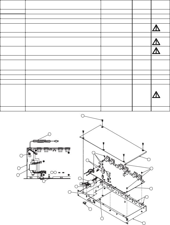
MAIN PART LIST
502C Controller (one-piece chassis version) (see Figure 8)
Item |
Description |
Part Number |
Qty/ |
Note |
Number |
|
|
Assy. |
|
1 |
Screw, 6-32, Mach, Flat, Xrec |
190623-008 |
5 |
|
2 |
Screw, Mach, 4-40x.25, PAN, XREC |
103140-04 |
9 |
|
3 |
Clip, Heatsink |
188599 |
2 |
|
4 |
XFMR, US/Canada/Japan, 100V/120V |
180128-1 |
1 |
5 |
|
EUR/AUS/UK, 220V/240V |
180128-2 |
1 |
|
5 |
Nut, Hex, 8-32, Keps |
118260-08 |
3 |
|
6 |
Insulator, 9.25x7.56x.015, D/C |
143948 |
1 |
1, 5 |
7 |
Switch, Power, Rocker, SPST |
143960 |
1 |
5 |
8 |
Lens, LED, Clear, Chassis |
144023 |
1 |
|
9 |
Chassis, 502®, US/Canada |
198373-001 |
1 |
1 |
|
Euro/UK/AUS/Japan |
198373-002 |
1 |
|
10 |
Screw, Tapp, 4-40x.375, PAN, XREC |
170284-06 |
6 |
|
11 |
PCB Assy, 502 (all versions) |
143940-2 |
1 |
1, 6 |
12 |
Cover, Chassis, Controller |
198374-001 |
1 |
|
13 |
Line Cord, 3-Wire, USA/Canada |
173242 |
1 |
5 |
|
2-Wire, EU |
173243 |
1 |
|
|
2-Wire, Japan |
173244 |
1 |
|
|
3-Wire, UK |
173245 |
1 |
|
|
3-Wire, Aus |
173246 |
1 |
|
14 |
Tape, Foam, 0.50" |
198408 |
1 |
|
|
1 |
|
|
|
|
5X |
|
|
|
13 |
|
|
|
|
|
|
2 |
5 |
|
|
|
|
|
3 |
12 |
|
|
|
|
9 |
|
|
2 |
C114 |
C113 |
|
|
4 |
|
|
|
|
|
4 |
|
14 |
|
|
|
|
5 |
2X |
11 |
|
|
|
|
|
6 |
|
|
|
|
|
10 |
|
|
|
6X |
7
8
9
Figure 8. 502C Controller Exploded View (one-piece chassis version)
20
 Loading...