


3•2•1GS Series II
3•2•1 Series II
D V D H O M E E N T E R T A I N M E N T S Y S T E M S
Owner’s Guide
®
Svenska |
Nederlands |
FrançaisItliano |
DeutschEspañol |
EnglishDansk |
SAFETY INFORMATION
Please read this owner’s guide
Please take the time to follow this owner’s guide carefully. It will help you set up and operate your system properly, and enjoy all of its advanced features. Save your owner’s guide for future reference.
 WARNING: To reduce the risk of fire or electric shock, do not expose the system to rain or moisture.
 WARNING: This apparatus shall not be exposed to dripping or splashing, and objects filled with liquids, such as vases, shall not be placed on the apparatus. As with any electronic products, use care not to spill liquids in any part of the system. Liquids can cause a failure and/or a fire hazard.
The CAUTION marks shown here are located on the bottom of your 3•2•1 Series II home entertainment system media center and the rear panel of the Acoustimass module:
The lightning flash with arrowhead symbol, within an equilateral triangle, alerts the user to the presence of uninsulated dangerous voltage within the system enclosure that may be of sufficient magnitude to constitute a risk of electric shock.
The exclamation point within an equilateral triangle alerts the user to the presence of important operating and maintenance instructions in this owner’s guide.
CAUTION: To prevent electric shock, match wide blade of plug to wide slot, insert fully.
CAUTION: No naked flame sources, such as lighted candles, should be placed on the apparatus.
Class 1 laser product
This CD player is classified as a CLASS 1 LASER PRODUCT according to EN 60825-1:1994+A1+A2, IEC60825-1:1993+A1+A2.
CLASS 1 LASER PRODUCT
KLASSE 1 LASER PRODUKT LUOKAN 1 LASER LAITE KLASS 1 LASER APPARAT
CAUTION: Use of controls or adjustments or performance of procedures other than those specified herein may result in hazardous radiation exposure. The DVD player should not be adjusted or repaired by anyone except properly qualified service personnel.
Class B emissions limits
This Class B digital apparatus meets all requirements of the Canadian Interference-Causing Equipment Regulations.
Batteries
Please dispose of used batteries properly, following any local regulations. Do not incinerate.
This product conforms to the EMC Directive 89/336/EEC and to the Low Voltage Directive 73/23/EEC. The complete Declaration of Conformity can be found on www.bose.com.
Additional safety information
See the additional instructions on the Important Safety Information sheet enclosed in the shipping carton.
2

EnglishDansk |
DeutschEspañol |
FrançaisItliano |
Nederlands |
Svenska |
|
|
|
|
|
|
CONTENTS |
|
|
|
|
|
INTRODUCTION |
|
|
|
|
|
SYSTEM SETUP |
|
|
|
|
|
SYSTEM CONTROLS AND INDICATORS |
|
|
|
|
|
OPERATION |
|
|
|
|
|
CHANGING SOURCE SETTINGS |
|
|
|
|
|
CHANGING SYSTEM OPTIONS |
|
|
|
|
|
MAINTAINING YOUR SYSTEM |
|
|
|
|
|
TROUBLESHOOTING |
INTRODUCTION |
|
|
|
|
5 |
Before you begin . . . . . . . . . . |
. . . . . . . . . . . |
. . . . . . . . . . . . . . |
. . . . . . . . . . . . . . . . . . |
. . . . . . . . . . . . . . . . . . . . . . . . 5 |
|
System features |
. . . . . . . . . . . |
. . . . . . . . . . . |
. . . . . . . . . . . . . . |
. . . . . . . . . . . . . . . . . . . |
. . . . . . . . . . . . . . . . . . . . . . . 5 |
Selecting compatible discs . . . |
. . . . . . . . . . . |
. . . . . . . . . . . . . |
. . . . . . . . . . . . . . . . . . . |
. . . . . . . . . . . . . . . . . . . . . . . 5 |
|
Checking for region code compatibility . . . . . |
. . . . . . . . . . . . . |
. . . . . . . . . . . . . . . . . . . |
. . . . . . . . . . . . . . . . . . . . . . . 6 |
||
Glossary of terms . . . . . . . . . . . |
. . . . . . . . . . . |
. . . . . . . . . . . . . |
. . . . . . . . . . . . . . . . . . . |
. . . . . . . . . . . . . . . . . . . . . . . 6 |
|
Limited warranty . . . . . . . . . . . . |
. . . . . . . . . . . |
. . . . . . . . . . . . . |
. . . . . . . . . . . . . . . . . . . |
. . . . . . . . . . . . . . . . . . . . . . . 7 |
|
For your records . . . . . . . . . . . . |
. . . . . . . . . . . |
. . . . . . . . . . . . . |
. . . . . . . . . . . . . . . . . . . |
. . . . . . . . . . . . . . . . . . . . . . . 7 |
|
SYSTEM SETUP |
|
|
|
8 |
|
Unpacking . . . . |
. . . . . . . . . . . . |
. . . . . . . . . . . |
. . . . . . . . . . . . . |
. . . . . . . . . . . . . . . . . . . |
. . . . . . . . . . . . . . . . . . . . . . . 8 |
Selecting locations for your 3•2•1 Series II system components . . . . . . . . . . . . . . . . . |
. . . . . . . . . . . . . . . . . . . . . . . 9 |
||||
Placing the media center |
. . . . . . . . . . . |
. . . . . . . . . . . . . |
. . . . . . . . . . . . . . . . . . . |
. . . . . . . . . . . . . . . . . . . . . . . 9 |
|
Placing the speakers . . . |
. . . . . . . . . . . |
. . . . . . . . . . . . . |
. . . . . . . . . . . . . . . . . . . |
. . . . . . . . . . . . . . . . . . . . . . . 10 |
|
Placing the Acoustimass® module . . . . |
. . . . . . . . . . . . . |
. . . . . . . . . . . . . . . . . . . |
. . . . . . . . . . . . . . . . . . . . . . . 11 |
||
Making system connections . . |
. . . . . . . . . . . |
. . . . . . . . . . . . . |
. . . . . . . . . . . . . . . . . . . |
. . . . . . . . . . . . . . . . . . . . . . . 12 |
|
Connecting the Acoustimass module to the media center . . . . . . . . . . . . . . . . . |
. . . . . . . . . . . . . . . . . . . . . . . 12 |
||||
Connecting the speakers to the Acoustimass module . |
. . . . . . . . . . . . . . . . . . . |
. . . . . . . . . . . . . . . . . . . . . . . 12 |
|||
Connecting the supplied antennas . . . . |
. . . . . . . . . . . . . |
. . . . . . . . . . . . . . . . . . . |
. . . . . . . . . . . . . . . . . . . . . . . 14 |
||
Connecting cable FM radio . . . . . . . . . |
. . . . . . . . . . . . . |
. . . . . . . . . . . . . . . . . . . |
. . . . . . . . . . . . . . . . . . . . . . . 14 |
||
Connecting your TV to the media center . . . . |
. . . . . . . . . . . . . |
. . . . . . . . . . . . . . . . . . . |
. . . . . . . . . . . . . . . . . . . . . . . 15 |
||
Making audio connections . . . . . . . . . . |
. . . . . . . . . . . . . |
. . . . . . . . . . . . . . . . . . . |
. . . . . . . . . . . . . . . . . . . . . . . 15 |
||
Making composite video connections . |
. . . . . . . . . . . . . |
. . . . . . . . . . . . . . . . . . . |
. . . . . . . . . . . . . . . . . . . . . . . 15 |
||
Connecting your TV and VCR to the media center . . . . . . . . . |
. . . . . . . . . . . . . . . . . . . |
. . . . . . . . . . . . . . . . . . . . . . . 16 |
|||
If your TV has audio output jacks . . . . . |
. . . . . . . . . . . . . |
. . . . . . . . . . . . . . . . . . . |
. . . . . . . . . . . . . . . . . . . . . . . 16 |
||
If your TV does not have audio output jacks . . . . . . . . . |
. . . . . . . . . . . . . . . . . . . |
. . . . . . . . . . . . . . . . . . . . . . . 17 |
|||
VCR considerations . . . . |
. . . . . . . . . . . |
. . . . . . . . . . . . . |
. . . . . . . . . . . . . . . . . . . |
. . . . . . . . . . . . . . . . . . . . . . . 18 |
|
Advanced setup options . . . . . |
. . . . . . . . . . . |
. . . . . . . . . . . . . |
. . . . . . . . . . . . . . . . . . . |
. . . . . . . . . . . . . . . . . . . . . . . 18 |
|
Making S-video connections (higher quality video) . . . . |
. . . . . . . . . . . . . . . . . . . |
. . . . . . . . . . . . . . . . . . . . . . . 18 |
|||
Making component video connections (highest quality video) . . . . . . . . . . . . . . |
. . . . . . . . . . . . . . . . . . . . . . . 19 |
||||
Connecting digital audio devices . . . . . |
. . . . . . . . . . . . . |
. . . . . . . . . . . . . . . . . . . |
. . . . . . . . . . . . . . . . . . . . . . . 20 |
||
Connecting your cable/satellite box, TV, and VCR to the media center . . . . . . . |
. . . . . . . . . . . . . . . . . . . . . . . 20 |
||||
Connecting a game console . . . . . . . . . |
. . . . . . . . . . . . . |
. . . . . . . . . . . . . . . . . . . |
. . . . . . . . . . . . . . . . . . . . . . . 22 |
||
Installing the remote control batteries . . . . . . |
. . . . . . . . . . . . . |
. . . . . . . . . . . . . . . . . . . |
. . . . . . . . . . . . . . . . . . . . . . . 23 |
||
Connecting the power cord . . . |
. . . . . . . . . . . |
. . . . . . . . . . . . . |
. . . . . . . . . . . . . . . . . . . |
. . . . . . . . . . . . . . . . . . . . . . . 24 |
|
Checking your system setup . . |
. . . . . . . . . . . |
. . . . . . . . . . . . . |
. . . . . . . . . . . . . . . . . . . |
. . . . . . . . . . . . . . . . . . . . . . . 25 |
|
SYSTEM CONTROLS AND INDICATORS |
|
|
26 |
||
Remote control . |
. . . . . . . . . . . . |
. . . . . . . . . . . |
. . . . . . . . . . . . . |
. . . . . . . . . . . . . . . . . . . |
. . . . . . . . . . . . . . . . . . . . . . . 26 |
Setting up your remote to control other audio/video devices . |
. . . . . . . . . . . . . . . . . . . |
. . . . . . . . . . . . . . . . . . . . . . . 30 |
|||
Direct entry of a device code . . . . . . . . |
. . . . . . . . . . . . . |
. . . . . . . . . . . . . . . . . . . |
. . . . . . . . . . . . . . . . . . . . . . . 30 |
||
Searching for a device code . . . . . . . . . |
. . . . . . . . . . . . . |
. . . . . . . . . . . . . . . . . . . |
. . . . . . . . . . . . . . . . . . . . . . . 31 |
||
Verifying an entered device code . . . . . |
. . . . . . . . . . . . . |
. . . . . . . . . . . . . . . . . . . |
. . . . . . . . . . . . . . . . . . . . . . . 33 |
||
Changing the default channel tuner assignment . . . . . . . . . . . |
. . . . . . . . . . . . . . . . . . . |
. . . . . . . . . . . . . . . . . . . . . . . 33 |
|||
The media center . . . . . . . . . . . |
. . . . . . . . . . . |
. . . . . . . . . . . . . |
. . . . . . . . . . . . . . . . . . . |
. . . . . . . . . . . . . . . . . . . . . . . 34 |
|
5
8
26
35
40
45
53
55
3

Svenska |
Nederlands |
FrançaisItliano |
DeutschEspañol |
EnglishDansk |
|
|
|
|
|
|
|
|
|
|
OPERATION |
35 |
Turning your system on and off . . . . . . . . . . . . . . . . . . . . . . . . . . . . . . . . . . . . . . . . . . . . . . . . . . . . . . . . . . . . . . . . . |
. 35 |
Playing video DVDs . . . . . . . . . . . . . . . . . . . . . . . . . . . . . . . . . . . . . . . . . . . . . . . . . . . . . . . . . . . . . . . . . . . . . . . . . . . |
35 |
Basic DVD operations . . . . . . . . . . . . . . . . . . . . . . . . . . . . . . . . . . . . . . . . . . . . . . . . . . . . . . . . . . . . . . . . . . . . |
36 |
Restricting access to video DVDs . . . . . . . . . . . . . . . . . . . . . . . . . . . . . . . . . . . . . . . . . . . . . . . . . . . . . . . . . . . |
36 |
Playing audio CDs . . . . . . . . . . . . . . . . . . . . . . . . . . . . . . . . . . . . . . . . . . . . . . . . . . . . . . . . . . . . . . . . . . . . . . . . . . . . |
37 |
Listening to FM/AM radio . . . . . . . . . . . . . . . . . . . . . . . . . . . . . . . . . . . . . . . . . . . . . . . . . . . . . . . . . . . . . . . . . . . . . . . |
38 |
Tuning to a station . . . . . . . . . . . . . . . . . . . . . . . . . . . . . . . . . . . . . . . . . . . . . . . . . . . . . . . . . . . . . . . . . . . . . . . |
38 |
Storing stations as presets . . . . . . . . . . . . . . . . . . . . . . . . . . . . . . . . . . . . . . . . . . . . . . . . . . . . . . . . . . . . . . . . . |
38 |
Erasing a preset . . . . . . . . . . . . . . . . . . . . . . . . . . . . . . . . . . . . . . . . . . . . . . . . . . . . . . . . . . . . . . . . . . . . . . . . . |
39 |
Playing other sources . . . . . . . . . . . . . . . . . . . . . . . . . . . . . . . . . . . . . . . . . . . . . . . . . . . . . . . . . . . . . . . . . . . . . . . . . . |
39 |
Using the sleep timer . . . . . . . . . . . . . . . . . . . . . . . . . . . . . . . . . . . . . . . . . . . . . . . . . . . . . . . . . . . . . . . . . . . . . . . . . . |
39 |
CHANGING SOURCE SETTINGS |
40 |
Using the settings menus . . . . . . . . . . . . . . . . . . . . . . . . . . . . . . . . . . . . . . . . . . . . . . . . . . . . . . . . . . . . . . . . . . . . . . . |
40 |
FM/AM settings menu . . . . . . . . . . . . . . . . . . . . . . . . . . . . . . . . . . . . . . . . . . . . . . . . . . . . . . . . . . . . . . . . . . . . . . . . . |
42 |
CD settings menu . . . . . . . . . . . . . . . . . . . . . . . . . . . . . . . . . . . . . . . . . . . . . . . . . . . . . . . . . . . . . . . . . . . . . . . . . . . . . |
42 |
DVD settings menu . . . . . . . . . . . . . . . . . . . . . . . . . . . . . . . . . . . . . . . . . . . . . . . . . . . . . . . . . . . . . . . . . . . . . . . . . . . |
43 |
TV, CBL•SAT, and AUX settings menu . . . . . . . . . . . . . . . . . . . . . . . . . . . . . . . . . . . . . . . . . . . . . . . . . . . . . . . . . . . . |
44 |
CHANGING SYSTEM OPTIONS |
45 |
Using the System menu . . . . . . . . . . . . . . . . . . . . . . . . . . . . . . . . . . . . . . . . . . . . . . . . . . . . . . . . . . . . . . . . . . . . . . . . |
45 |
Audio options . . . . . . . . . . . . . . . . . . . . . . . . . . . . . . . . . . . . . . . . . . . . . . . . . . . . . . . . . . . . . . . . . . . . . . . . . . . . . . . . |
47 |
Video options . . . . . . . . . . . . . . . . . . . . . . . . . . . . . . . . . . . . . . . . . . . . . . . . . . . . . . . . . . . . . . . . . . . . . . . . . . . . . . . . |
48 |
Media center options . . . . . . . . . . . . . . . . . . . . . . . . . . . . . . . . . . . . . . . . . . . . . . . . . . . . . . . . . . . . . . . . . . . . . . . . . . |
49 |
Remote control options . . . . . . . . . . . . . . . . . . . . . . . . . . . . . . . . . . . . . . . . . . . . . . . . . . . . . . . . . . . . . . . . . . . . . . . . |
50 |
DVD Lock options . . . . . . . . . . . . . . . . . . . . . . . . . . . . . . . . . . . . . . . . . . . . . . . . . . . . . . . . . . . . . . . . . . . . . . . . . . . . |
51 |
MAINTAINING YOUR SYSTEM |
53 |
Cleaning . . . . . . . . . . . . . . . . . . . . . . . . . . . . . . . . . . . . . . . . . . . . . . . . . . . . . . . . . . . . . . . . . . . . . . . . . . . . . . . . . . . . |
53 |
Replacing the remote control batteries . . . . . . . . . . . . . . . . . . . . . . . . . . . . . . . . . . . . . . . . . . . . . . . . . . . . . . . . . . . . |
54 |
Accessories . . . . . . . . . . . . . . . . . . . . . . . . . . . . . . . . . . . . . . . . . . . . . . . . . . . . . . . . . . . . . . . . . . . . . . . . . . . . . . . . . |
54 |
TROUBLESHOOTING |
55 |
Troubleshooting table . . . . . . . . . . . . . . . . . . . . . . . . . . . . . . . . . . . . . . . . . . . . . . . . . . . . . . . . . . . . . . . . . . . . . . . . . |
55 |
Customer service . . . . . . . . . . . . . . . . . . . . . . . . . . . . . . . . . . . . . . . . . . . . . . . . . . . . . . . . . . . . . . . . . . . . . . . . . . . . . |
56 |
TECHNICAL INFORMATION |
57 |
DEVICE CODES |
A-1 |
4

EnglishDansk |
DeutschEspañol |
FrançaisItliano |
Nederlands |
Svenska |
INTRODUCTION
Before you begin
Thank you for purchasing the Bose® 3•2•1 Series II or 3•2•1 GS Series II DVD home entertainment system, which offers superb sound, elegance, and simplicity in an advanced home audio setup. Using Bose proprietary signal processing technology, the 3•2•1 Series II systems provide improved spaciousness from stereo recordings, and bold movie effects from surround-encoded materials. Yet its few parts require little effort to set up, so you can enjoy your new system’s performance right away.
The following items are included to help you set up your system:
•Quick Setup Guide
•Detailed setup instructions in the Setup section of this guide
•Setup DVD
System features
•Integrated AM/FM tuner and DVD/CD player in a small console
•Small, easy-to-place shelf speakers and an attractive hideaway Acoustimass® module
•Easy-to-use infrared remote control
•Media center input jacks for a TV, cable/satellite box or other component such as a DVR
Selecting compatible discs
The DVD/CD player built into the 3•2•1 series II media center can play the following types of discs identified by their corresponding logos:
•Video DVD 
•Video CD 
•DVD-R and DVD-RW
• Audio CD
•CD-R and CD-R/W
•MP3 CDs, where
–All tracks were burned in a single closed session
–The disc format is ISO9660
–Each file has a “.mp3” extension and the filename contains no other periods
•SACDs (CD-compatible content only)
NTRODUCTIONI
5
INTRODUCTION
Svenska |
Nederlands |
FrançaisItliano |
DeutschEspañol |
EnglishDansk |
INTRODUCTION
Checking for region code compatibility
For a DVD player and DVD disc to be compatible, their region code numbers must match.
These numbers are allocated according to where the player and disc are sold. The 3•2•1
Series II DVD home entertainment systems have a region code which must also match the
DVD discs.
Check the region code number on the carton of the 3•2•1 Series II DVD home entertainment system or on the bottom of the media center that comes in the carton. Then be sure to choose only DVD discs that show the same region number on the disc label or front cover. For example, a Region 1 DVD disc should display the following mark: 
Glossary of terms
Aspect Ratio – The shape of the rectangular picture in a TV set. It is the width of the picture relative to the height. Our standard TV picture, in terminology used by that industry, is 4 units wide by 3 units high, or 4:3 (read as 4 by 3) in aspect ratio. There are currently two standard TV aspect ratios, 4:3 and 16:9.
Chapter – In DVD-Video, a division of a title. Technically called a part of title (PTT).
Component Video – A video signal split into three parts: luminance and two color signals (marked as YPbPr). It provides the highest resolution video, but cannot be processed by all television sets.
Composite Video – A single video signal that contains luminance, color, and synchronization information. NTSC and PAL are examples of composite video systems.
Dolby Laboratories 

 – Developer of a perceptual coding system for audio.
Dolby Digital – a type of multi-channel surround sound format used on discs.
– the logo representing Dolby® Digital.
DTS – a type of multi-channel surround sound format used on discs.
– the logo representing DTS.
DVD – An acronym that is most commonly known to mean Digital Video Disc or Digital
Versatile Disc. The audio/video/data storage system based on 12and 8-cm optical discs.
DVD Video – A standard for storing and reproducing audio and video on DVD-ROM discs, based on MPEG video, Dolby Digital and MPEG audio, and other proprietary data formats.
IR – An acronym for infrared. Pertains to the type of remote that sends/receives commands on an infrared light beam.
Letterbox – The projected aspect ratio of feature films is often 16:9 rather than the 4:3 aspect ratio of most TVs. Therefore, it is becoming common practice to transfer films to video with black borders at the top and bottom of the picture. The film picture becomes a “letterbox” within the video.
6

EnglishDansk |
DeutschEspañol |
FrançaisItliano |
Nederlands |
Svenska |
INTRODUCTION
MPEG – a type of data compression used for audio or video storage on disc.
MP3 – MPEG-1 Layer III audio. This is a compressed audio format that allows you to record many hours of music on a single CD.
NTSC – An acronym for National Television System Committee. The organization that developed both the American Black & White and Color television systems.
PAL – An acronym for Phase Alternate Line. A television format used extensively in Western Europe.
S-video – A video interface standard that carries separate luminance and chrominance signals, usually on a four-pin mini-DIN connector. Also called Y/C. The quality of S-video is significantly better than composite video since it does not require a comb filter to separate the signals. Most high-end televisions have S-video inputs.
Title – numbered elements of the DVD contents, which may include more than the movie alone.
Track – Individual selections recorded on an audio tape or disc.
Limited warranty
The 3•2•1 Series II and 3•2•1 GS Series II home entertainment systems are covered by a limited transferable warranty. Details of the limited warranty are provided on the product registration card that came with your system. Please fill out the information section on the card and mail it to Bose. Failure to do so will not affect your limited warranty rights.
For your records
Serial numbers are located on the bottom of the media center and the rear of the
Acoustimass® module. Please have your serial number ready before contacting Bose®
Customer Service.
Model: |
3•2•1 Series II |
3•2•1 GS Series II |
Check one |
Media center serial number: _________________________________________________________
Acoustimass module serial number: __________________________________________________
Dealer name: ______________________________________________________________________
Dealer phone: __________________________ Purchase date: _____________________________
We suggest you keep your sales receipt and product registration together with this owner’s guide.
NTRODUCTIONI
©2005 Bose Corporation. No part of this work may be reproduced, modified, distributed or otherwise used without prior written permission.
Dolby and the double-D symbol are trademarks of Dolby Laboratories. Manufactured under license from Dolby Laboratories. Confidential unpublished works. 1992-1997 Dolby Laboratories. All rights reserved.
This product incorporates copyright protection technology that is protected by method claims of certain U.S. patents and other intellectual property rights owned by Macrovision Corporation and other rights owners. Use of this copyright protection technology must be authorized by Macrovision Corporation, and is intended for home and other limited viewing uses only unless otherwise authorized by Macrovision Corporation. Reverse engineering or disassembly is prohibited.
“DTS” and “DTS Digital Surround” are registered trademarks of Digital Theater Systems, Inc.
MPEG Layer-3 audio compression technology licensed by Fraunhofer IIS and THOMSON multimedia.
This product incorporates copyright protected technology and other intellectual property rights owned by Cirrus Logic, Inc. and subject to the copyright protection of the U.S. as well as other licensing restrictions and protections. Use of this copyright protected technology is limited solely to use with the Cirrus Logic integrated circuits incorporated in this product. Reverse engineering or disassembly is prohibited.
7
SYSTEM SETUP
Svenska |
Nederlands |
FrançaisItliano |
DeutschEspañol |
EnglishDansk |
SYSTEM SETUP
Unpacking
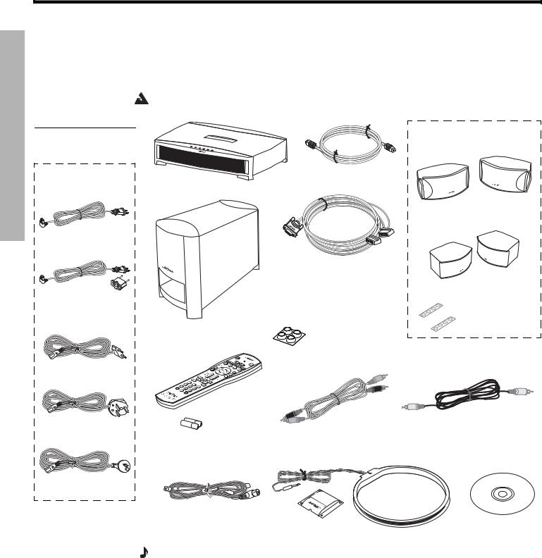
Figure 1
Contents of the shipping carton
Your system includes one of the following cords:
120 VAC power cord (U.S./Canada)
115/230 VAC power cord with adapter (U.S./Europe)
230 VAC power cord (Europe)
230 VAC power cord (U.K./Singapore)
240 VAC power cord (Australia)
Carefully unpack your system. Save all packing materials, which provide the safest way to transport your system. Check to be sure your system includes the parts shown in Figure 1.
If any part of the system appears damaged, do not attempt to use it. Notify Bose or your authorized Bose® dealer immediately. For Bose contact information, refer to the address sheet included in the carton.
WARNING: To avoid danger of suffocation, keep the plastic bags out of the reach of children.
Your system includes one the following speaker types:
|
Acoustimass® module |
Media center |
cable |
3•2•1 speakers
or
Speaker cable
Note: If you purchased a 3•2•1 GS Series II system, the left and right speaker cable connectors will be marked with a “GS”.
Acoustimass |
|
module |
Rubber feet for |
|
|
|
Acoustimass |
|
module |
3•2•1 GS speakers
Rubber feet for speakers
Remote
control
Batteries |
Stereo cable |
Video cable |
|
|
AM antenna |
|
FM antenna |
Setup and |
|
Antenna stand |
||
demo disc |
||
|
Note: Now is a good time to find the serial numbers on the bottom of the media center and Acoustimass module. Copy these numbers onto your product registration card and in the space provided on page 7.
8
EnglishDansk |
DeutschEspañol |
FrançaisItliano |
Nederlands |
Svenska |
SYSTEM SETUP
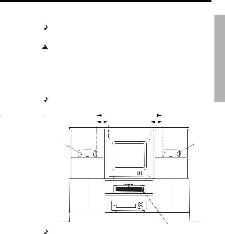
Selecting locations for your 3•2•1 Series II system components
Figure 2
Sample media center and speaker placement
Use the following guidelines and Figure 2 to choose locations and positions for the components of your 3•2•1 home entertainment system.
Note: While these guidelines are offered to help provide great system performance, you may find other placement choices that are more convenient and provide the sound you enjoy.
Placing the media center
CAUTION: Do not block any ventilation openings. For reliable operation of the product and to protect it from overheating, put the product in a position and location that will not interfere with its proper ventilation. For example, do not place the product on a bed, sofa, or similar surface that may block the ventilation openings. Do not put it in a built-in system, such as a bookcase or cabinet that may keep air from flowing through its ventilation openings.
•Place the media center where nothing obstructs opening the disc tray on its front panel.
•Make sure the media center will be placed close enough to the Acoustimass® module and the speakers so that all the cables will reach.
•Make sure the media center will be placed close enough to additional source devices (TV, VCR or cable box) so that all the cables will reach.
Note: Make sure that the front of the media center is unobstructed so that it may receive IR (infrared) commands from the remote control.
|
|
|
|
|
|
|
|
|
|
|
||
|
|
|
|
|
3 ft (1 m) |
|
|
|||||
3 ft (1 m) |
|
|
|
|
minimum |
|
|
|
|
|
3 ft (1 m) |
|
|
|
|
|
|||||||||
|
|
|
|
|
|
|
|
|
|
|
||
maximum |
|
|
|
|
|
|
|
|
|
|
|
maximum |
|
|
|
|
|
|
|
|
|
|
|
||
Left |
Right |
speaker |
speaker |
Media center
Note: The speakers are magnetically shielded to prevent interference with the TV screen.
ETUPS YSTEMS
9
SYSTEM SETUP
Svenska |
Nederlands |
FrançaisItliano |
DeutschEspañol |
EnglishDansk |
SYSTEM SETUP
Placing the speakers
Figure 3
Recommended speaker placement
Choosing a good location for the speakers will allow you to experience the audio surround effects that your 3•2•1 home entertainment system is designed to deliver.
•Place the two speakers either on top of the TV or at equal distance from the left and right of the TV screen (Figure 2). Keep both speakers at approximately the same height.
•Place each speaker within 3 feet (1 meter) of the edge of the TV screen. Placing the speakers more than 3 feet away from the TV can cause the sound to become separated from the picture.
•If you are using a bookshelf or a home entertainment unit, place each speaker at the front edge of its shelf Positioning the speakers too far back in an enclosed space can change the overall quality of sound and alter the movie sound effects.
•Place the speakers at least 3 feet (1 meter) apart from each other to optimize the surround sound experience.
CAUTION: Choose a stable and level surface for both speakers. Vibration can cause the speakers to move, particularly on smooth surfaces like marble, glass, or highly polished wood. If you are placing the speakers on a flat surface, be sure to attach the smaller of the two sets of supplied rubber feet to the bottom surface. You may obtain additional rubber feet (part number 178321) from Bose® Customer Service. To contact Bose, refer to the list of offices included in the product carton.
Note: The speakers can be mounted on Bose brackets, table stands, or floor stands. For ordering information, refer to “Accessories” on page 54. Additional or longer cables may also be ordered.
• Place the speakers only on their bottom surfaces, with the Bose logo right-side up.
•Aim the speakers straight ahead toward the listening area. Do not place the speakers at an angle. Angling one or both speakers into or away from the listening area significantly alters system performance.
10
EnglishDansk |
DeutschEspañol |
FrançaisItliano |
Nederlands |
Svenska |
SYSTEM SETUP
Placing the Acoustimass® module
•Place the Acoustimass® module within reach of the cable from the music center and an AC (mains) power outlet.
•Place the module at the same end of the room as the TV and the speakers (Figure 4).
•Keep the module at least 3 feet (1 meter) away from the TV to prevent the module from interfering with the TV screen.
Figure 4
Recommended Acoustimass module placement
3 ft (1 m) minimum
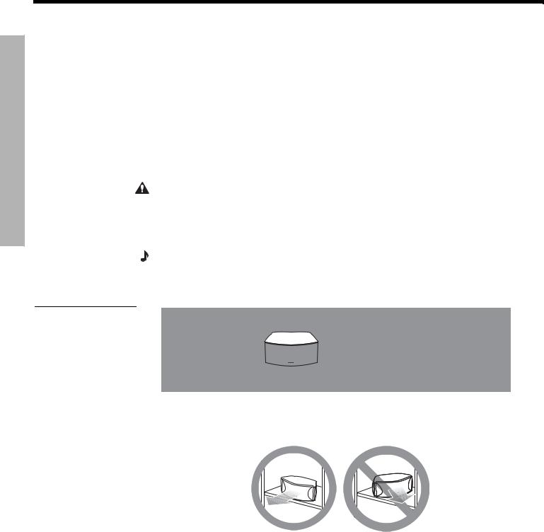
• Attach the medium-sized rubber feet to the bottom of each foot on the module. The rubber feet provide increased stability and protection from scratches.
•Choose a convenient location such as under a table, behind a sofa or chair, or behind drapes, but do not block the port opening.
•Aim the port of the module into the room or along the wall. This prevents a blocked port or over-powering bass.
•Stand the Acoustimass module on its feet. Do not lay it on its side or stand it on either end (Figure 5).
Figure 5
Recommended orientation of the module
 CAUTION: Do not block the openings on the back of the module, which provide ventilation for the built-in circuitry.
CAUTION: The Acoustimass module generates a magnetic field. Although this is not an immediate risk to your video tapes, audio tapes, and other magnetic media, you should not store any of these items directly on or near the module.
ETUPS YSTEMS
11
SYSTEM SETUP
Svenska |
Nederlands |
FrançaisItliano |
DeutschEspañol |
EnglishDansk |
SYSTEM SETUP
Making system connections
 CAUTION: Do not plug the Acoustimass® module into an AC power (mains) outlet until all the components are connected.
Note: If additional audio cables or longer cables are needed to make these connections, contact Bose Customer Service. Refer to the list of offices included in the product carton.
Connecting the Acoustimass module to the media center
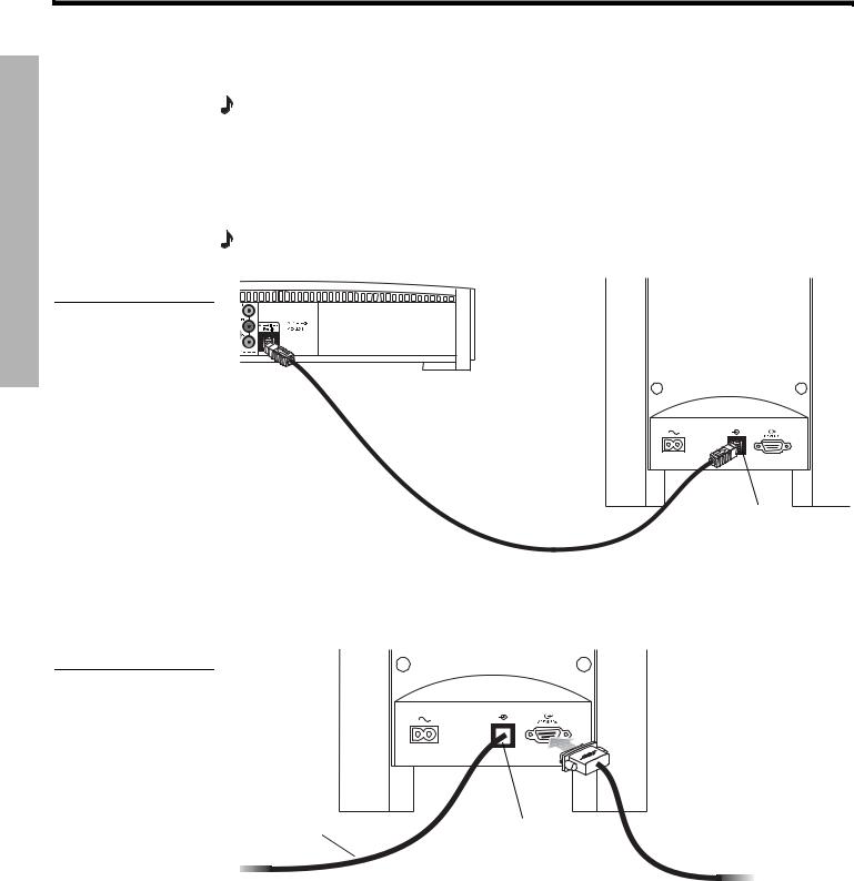
Plug one end of the Acoustimass module cable into the Acoustimass Module jack on the rear of the media center (Figure 6). Plug the other end of the cable into the input (  ) jack on the rear of the Acoustimass module.
Note: The jacks for the Acoustimass module cable are keyed so that the cable connectors only plug in one way. Make sure that the arrow on the connector body faces up when plugging in the cable.
Figure 6
Acoustimass module-to- media center connection
Media center rear panel
Acoustimass module cable
Acoustimass module input jack
Connecting the speakers to the Acoustimass module
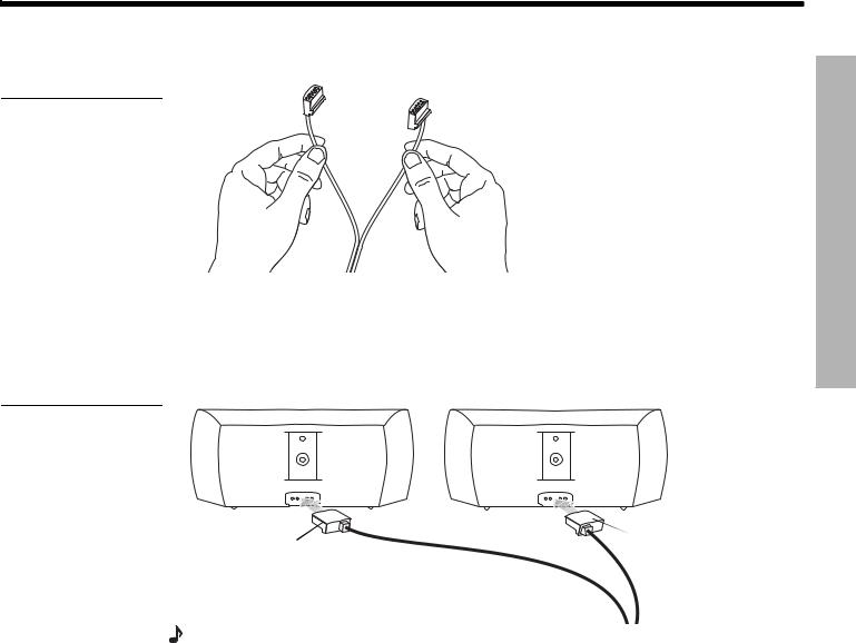
1.Insert the single-plug end of the speaker cable into the SPEAKERS jack on the rear panel of the Acoustimass module (Figure 7). Tighten both screws on the plug.
Figure 7
Speaker cable-to- Acoustimass module connection
|
Speaker |
|
Acoustimass |
cable |
|
Acoustimass |
||
module cable |
||
|
module input |
|
|
jack |
12
EnglishDansk |
DeutschEspañol |
FrançaisItliano |
Nederlands |
Svenska |
SYSTEM SETUP
2.At the other end of the speaker cable, separate the left and right speaker cords as much as necessary to reach each speaker (Figure 8).
Figure 8 |
Note: If you purchased a 3•2•1 |
Separating left and right |
GS Series II system, the left and |
speaker cords |
right speaker cable connectors |
|
will be marked with a “GS”. |
3.Plug the LEFT speaker cable into the rear jack of the left speaker (Figure 9). Plug the RIGHT speaker cable into the rear jack on the right speaker.
Figure 9
Left and right speaker connections
T |
|
T |
H |
|
|
RIG |
EF |
|
|
L |
|
RIGHT |
LEFT |
|
speaker |
||
speaker |
||
cable |
||
cable |
||
|
Note: Make sure cable connectors are fully inserted and seated firmly in the speaker jacks.
ETUPS YSTEMS
13
SYSTEM SETUP
Svenska |
Nederlands |
FrançaisItliano |
DeutschEspañol |
EnglishDansk |
SYSTEM SETUP
Connecting the supplied antennas
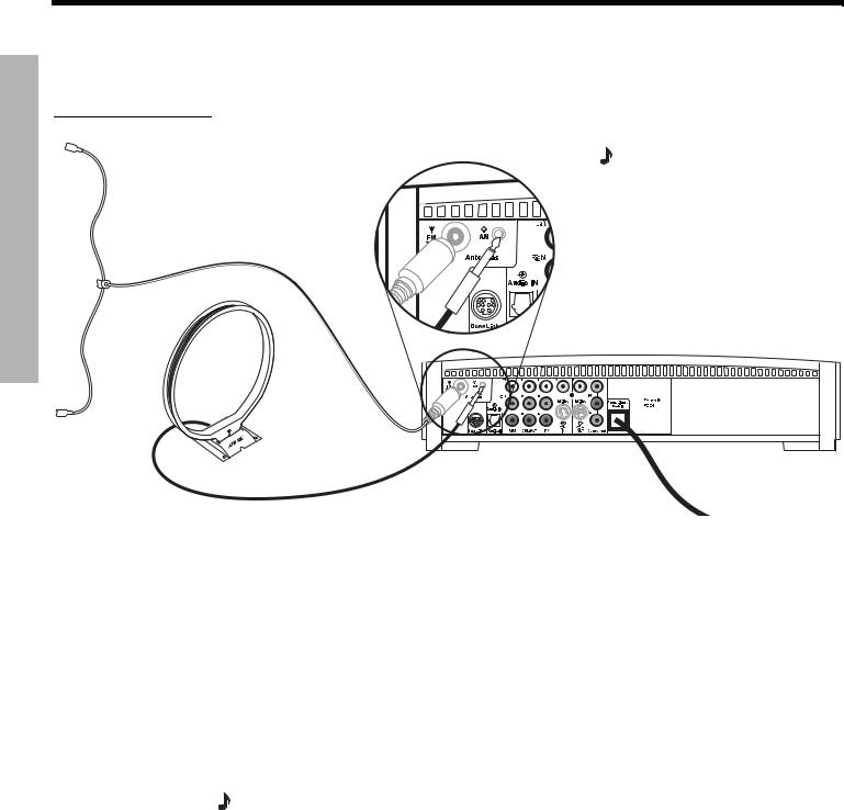
The rear panel of the media center provides jacks for the AM and FM antennas included with your system (Figure 10). Unwind the wires for each antenna to provide the best reception.
Figure 10
Antenna connections
FM dipole antenna
AM loop antenna
FM antenna
Note: An outdoor antenna may be used in place of the supplied indoor antennas. To add an outdoor antenna, consult a qualified installer. Follow all safety instructions supplied with the antenna.
Media center
Plug the FM antenna into the FM jack on the media center rear panel. Spread out the antenna arms and move them around to establish optimum FM reception. Extend the antenna as far from the media center and other equipment as possible.
AM antenna
Plug the AM loop antenna into the AM jack on the media center rear panel. Place the antenna loop at least 20 inches (50 centimeters) away from the media center and at least 4 feet (1.2 meters) away from the Acoustimass® module. Experiment with positioning the loop for optimum AM reception. Follow the instructions enclosed with the AM loop antenna to stand it on the supplied base, or mount it to a wall.
Connecting cable FM radio
Some cable TV providers make FM radio signals available through the cable service to your home. This connection is made to the external FM jack on the back panel of the media center. To connect to this service, contact your cable TV provider for assistance.
Note: Make sure that the cable radio installation includes a TV/FM splitter so that only the
FM radio band, not the cable TV band, is received by the media center. If necessary, contact your cable company.
14
EnglishDansk |
DeutschEspañol |
FrançaisItliano |
Nederlands |
Svenska |
SYSTEM SETUP
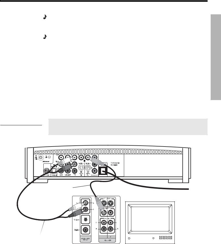
Connecting your TV to the media center
Figure 11
TV (composite video)-to- media center connections
Note: If you will be using the 3•2•1 system with both a TV and a VCR, skip this section and go to “Connecting your TV and VCR to the media center” on page 16.
Making audio connections
Note: If your TV does not have audio output jacks, see “If your TV does not have audio output jacks” on page 17. Otherwise, continue.
1.Connect one end of the supplied stereo cable to the TV Audio IN jacks on the rear panel of the media center (Figure 11). Insert the white RCA plug into the TV white L jack. Insert the red RCA plug into the TV red R jack.
2.Connect the other end of the stereo cable to the audio output jacks on your TV. Insert the white RCA plug into the white AUDIO OUT L jack. Insert the red RCA plug into the red
AUDIO OUT R jack.
Making composite video connections
 Note: Some older TVs with standard TV cable connectors do not have a composite video or an S-video input. Such TVs are not compatible with any DVD players and require use of an RF modulator for this connection. RF modulators are available at your local electronics store.
1.Insert one end of the supplied video cable (yellow) to the Video OUT C (composite) jack on the back of the media center (Figure 11).
2.Insert the other end of the video cable into one of the video input jacks on your TV.
Write the name of the video input jack used on your TV in the box on page 25. After you turn on the system, you will need to select this video input on your TV in order to view the 3•2•1 system video output.
Media center rear panel
ETUPS YSTEMS
Video cable |
|
(yellow connectors) |
TV connector panel |
|
TV
Stereo cable |
* |
(red and white connectors) |
|
*Could be labelled “FIXED”, “MONITOR”, or “HiFi”.
15
SYSTEM SETUP
Svenska |
Nederlands |
FrançaisItliano |
DeutschEspañol |
EnglishDansk |
SYSTEM SETUP
Connecting your TV and VCR to the media center
Figure 12
TV and VCR connections with media center
Note: There are two options for connecting your TV and VCR to the media center. Before you proceed, you must determine if your TV has audio output jacks. Consult your TV owner’s guide if you need assistance.
If your TV has audio output jacks
If your TV has audio output jacks, you can directly route the TV audio to the 3•2•1 home entertainment system (Figure 12).
1.Connect one end of the supplied stereo cable to the TV Audio IN jacks on the rear panel of the media center. Insert the white RCA plug into the TV white L jack. Insert the red RCA plug into the TV red R jack.
2.Connect the other end of the stereo cable to the audio output jacks on your TV. Insert the white RCA plug into the white AUDIO OUT L jack. Insert the red RCA plug into the red
AUDIO OUT R jack.
3.Insert one end of the supplied video cable (yellow) to the Video OUT C (composite) jack on the back of the media center. Insert the other end of the video cable into one of the video input jacks on your TV.
Write the name of the video input jack used on your TV in the box on page 25. After you turn on the system, you will need to select this video input on your TV in order to view the 3•2•1 system video output.
Cable/satellite box (if applicable)
Existing cable
VCR
|
TV connector |
Existing |
|
Video cable |
cable |
||
panel |
TV |
||
(yellow connectors) |
Stereo cable  (red and white connectors)


 *
*
*Could be labelled “FIXED”, “MONITOR”, or “HiFi”.
16

EnglishDansk |
DeutschEspañol |
FrançaisItliano |
Nederlands |
Svenska |
SYSTEM SETUP
If your TV does not have audio output jacks
If your TV does not have audio output jacks, you will need to feed audio to the 3•2•1 home entertainment system through a secondary source, such as a VCR. To do this, you will need one additional video cable, which can be purchased at your local electronics store.
1.Connect one end of the supplied stereo cable to the AUX Audio IN jacks on the rear panel of the media center (Figure 13). Insert the white RCA plug into the AUX white L jack. Insert the red RCA plug into the AUX red R jack.
2.Connect the other end of the stereo cable to the AUDIO OUT jacks on your VCR. Insert the white RCA plug into the white AUDIO OUT L jack. Insert the red RCA plug into the red AUDIO OUT R jack.
3.Insert one end of the supplied video cable (yellow) into the VIDEO OUT jack on the back of your VCR. Insert the other end of the supplied video cable into the Video IN C (composite) jack on the back of the media center.
4.Insert one end of the second video cable (yellow) into the Video OUT C (composite) jack on the back of the media center. Insert the other end of the second video cable into one of the video input jacks on your TV.
Figure 13 |
|
Write the name of the video input jack used on your TV in the box on page 25. After |
|
System setup when TV has |
|
you turn on the system, you will need to select this video input on your TV in order |
|
no audio output jacks |
|
to view the 3•2•1 system video output. |
|
|
|
|
|
|
Cable/satellite box |
|
|
Existing |
|
Video cables |
cable |
|
VCR |
||
(yellow connector) |
||
Media center rear panel |
|
|
VCR |
Existing |
|
connection |
|
Stereo cable |
panel |
cable |
|
||
(red and white connectors) |
|
|
IMPORTANT |
|
|
If you connected your TV and VCR this way, you |
TV |
|
will need to turn on your VCR and select the |
|
AUX source on the 3•2•1 remote to hear sound from TV programs.
TV connection panel
ETUPS YSTEMS
17
SYSTEM SETUP
Svenska |
Nederlands |
FrançaisItliano |
DeutschEspañol |
EnglishDansk |
SYSTEM SETUP
VCR considerations
•Some combination TV/VCR units may not work with 3•2•1 Series II home entertainment systems. Please refer to your TV/VCR owner’s manual for information.
•A stereo VCR is required for optimal sound performance. If your VCR has only one audio output and is not labeled Stereo or Hi-fi, you have a mono VCR. You will need a Y-adapter cable (available at electronics stores) to connect audio to the media center. For this setup, you will need to select “Mono decoding” (see “TV, CBL•SAT, and AUX settings menu” on page 44) so your 3•2•1 system will simulate surround sound effects from a mono source. Otherwise, you will hear mono sound from both speakers.
Advanced setup options
Figure 14
TV (S-video)-to-media center connections
IMPORTANT
If you use S-video to connect your TV to the media center, you must also use S-video to connect all other devices (such as a cable box and VCR) to the media center.
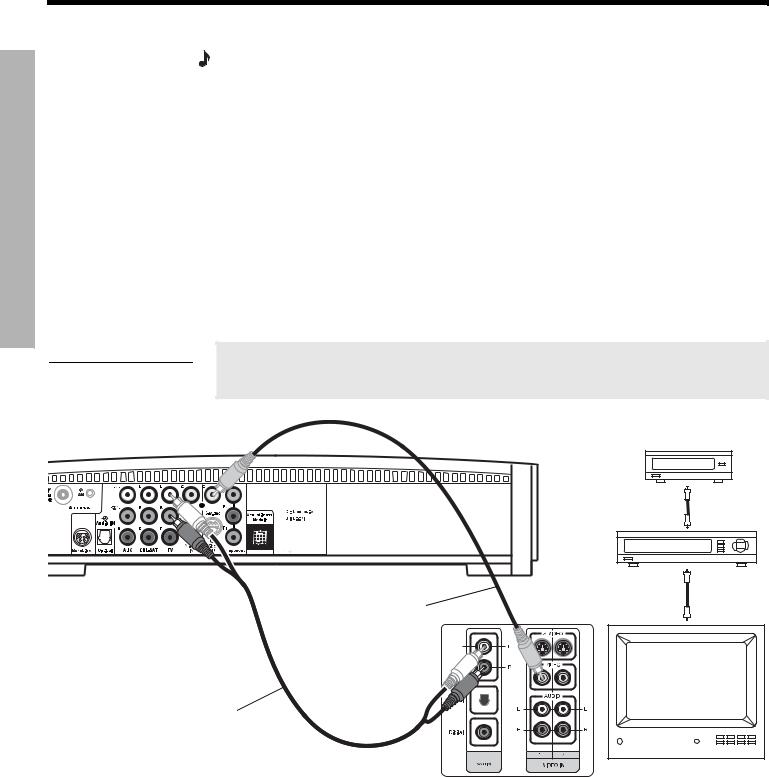
Making S-video connections (higher quality video)
An S-video input jack, provided on many TVs, delivers a higher quality TV picture than the composite video output connection shown in Figure 11. For this connection you will need an S-video cable which can be purchased from your Bose dealer or a local electronics retailer.
•Insert one end of the S-video cable into the S-Video OUT jack on the media center (Figure 14).
•Insert the other end of the S-video cable into the S-VIDEO IN jack on your TV.
Media center rear panel
S-video cable
TV connector panel
TV
Stereo cable
(red and white connectors)
18
EnglishDansk |
DeutschEspañol |
FrançaisItliano |
Nederlands |
Svenska |
SYSTEM SETUP
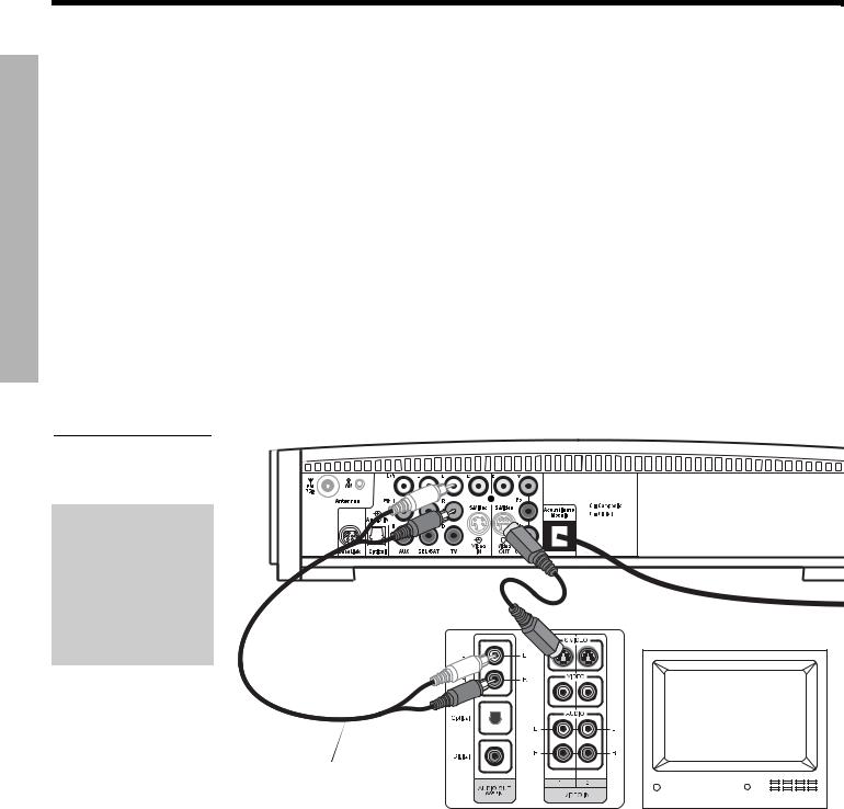
Making component video connections (highest quality video)
Note: Component video connections are required in order to use the progressive scan feature of your 3•2•1 system. Your TV must also support this feature. To turn on the progressive scan feature, see “Video options” on page 48.
For the highest quality video from DVDs, you may want to use a component video connection between the media center and the TV. To do so, your TV must provide component video jacks (typically labelled Y, Pb, and Pr). Refer to your TV owner’s guide for more information.
To make component video connections you will need three video grade cables that are long enough to reach from the rear of the media center to your TV (Figure 15). If the cables are not supplied with your TV, you can purchase them separately.
1.On the media center rear panel, plug one video cable into the Component Y, Pb, and Pr video output jacks (Figure 15).
2.Plug the other end of each video cable into the corresponding (color or letter code) component video jack on the back of your TV.
Figure 15 |
Color-coded component video |
||
jacks (Y, Pb, and Pr) |
|||
|
Media center rear panel |
||
|
|||
TV (component video)-to- media center connections
TV connector panel
Component
video cable
Stereo cable
(red and white connectors)
ETUPS YSTEMS
IMPORTANT FOR COMPONENT VIDEO USERS
Input signals received by the C (Composite) or S-Video IN jacks are not passed through to the Component video OUT jacks. If you connect an external video device to the C or S-Video IN jack, you must also connect the C or S-Video OUT jack on the media center to the respective video input jack on your TV. To view the external video input on your TV, you will need to select the TV video input used for that device. To view the onscreen menus of the 3•2•1 system, you will need to switch back to the TV’s component video input.
Note: For more information, or to purchase the video cables, contact your local electronics store or authorized Bose dealer.
19

SYSTEM SETUP
Svenska |
Nederlands |
FrançaisItliano |
DeutschEspañol |
EnglishDansk |
SYSTEM SETUP
Connecting digital audio devices
Some audio devices may feature a digital audio output for optimum sound performance. Use an optical digital cable or a coaxial digital cable, as appropriate, to connect this output to the digital input on the media center. You can purchase the required cables at a local electronics store.
On the media center rear panel, an optical digital cable connects to the OPTICAL jack. A coaxial cable connects to the audio input jacks labeled D.
Note: Before you can benefit from the optical connection, you will need to assign the optical connector to the audio source in the system settings menu. See “Media center options” on page 49.
Figure 16
Media center digital audio input jacks
|
|
|
|
|
|
|
|
|
|
|
|
|
|
|
|
|
|
|
|
|
|
|
|
|
|
|
|
|
|
|
|
|
|
|
|
|
|
|
|
|
|
|
|
|
|
|
|
|
|
|
|
|
|
|
|
|
|
|
|
|
|
|
|
|
|
|
|
|
|
|
|
|
|
|
|
|
|
|
|
|
|
|
|
|
|
|
|
|
|
Optical digital |
Coaxial digital |
|
|
|
|
|
|||||||||||
audio input |
audio inputs |
|
|
|
|
|
|||||||||||
Connecting your cable/satellite box, TV, and VCR to the media center
The 3•2•1 home entertainment system provides flexibility for you to add up to three external audio devices, including your TV, directly to the media center.
Figure 17 shows you an advanced setup using a TV, VCR and cable/satellite box. In this setup, please notice the following:
•S-video connections are used to deliver the cable/satellite signal to the media center. Therefore, the media center output video is sent to the TV also through an S-video connection.
•Analog and digital coax audio connections are shown for the cable/satellite box. As an option, you may use an optical digital connection. However, before you can benefit from the optical connection, you will need to assign the optical connector to the cable/satellite box audio source in the system settings menu. See “Media center options” on page 49.
•When connecting an audio device to the media center jacks, remember to match the red jack to the right channel (R) and the white (or black) jack to the left channel (L).
•For further details on making the video connections between your VCR and TV, refer to the manuals for these video devices.
 Note: The recommendations contained in this owner’s guide are basic suggestions for connecting external devices to the 3•2•1 Series II system. Instructions and terminology pertinent to these external devices may vary, depending on the manufacturer. Consult the owner’s guide that came with the device for clarification on setup and usage before making any connections.
20

EnglishDansk |
DeutschEspañol |
FrançaisItliano |
Nederlands |
Svenska |
SYSTEM SETUP
Figure 17
Advanced setup: TV, VCR and cable satellite box
Media center
Cable/satellite
(CBL SAT) service
CBL SAT |
Cable/satellite |
|
S-video |
||
|
||
output |
|
CBL SAT analog |
CBL SAT |
CBL SAT |
audio |
signal to |
|
|
digital audio |
VCR |
VCR |
|
CBL SAT |
|
VCR analog audio |
signal to |
|
TV |
||
|
Media center’s S-video output to TV
TV |
ETUPS YSTEMS
Note: For more information on advanced connections, refer to the DVD setup disc that came with your 3•2•1 Series II home entertainment system.
21

SYSTEM SETUP
Svenska |
Nederlands |
FrançaisItliano |
DeutschEspañol |
EnglishDansk |
SYSTEM SETUP
Connecting a game console
Connect the audio output of a game console to the AUX Left and Right input jacks. Connect the video output of the game console to the C (composite) Video IN jack.
Figure 18
Game console connections
Media center
Game console connection panel
TV connection panel
IMPORTANT
If you connected your game console this way, you will need to select the AUX source on the 3•2•1 remote in order to hear sound from the game console.
22

EnglishDansk |
DeutschEspañol |
FrançaisItliano |
Nederlands |
Svenska |
SYSTEM SETUP
Installing the remote control batteries
Figure 19
Installing the batteries
1.On the back of the remote, slide open the battery compartment (Figure 19).
2.Insert the two supplied AA (IEC-R6) 1.5V batteries, or their equivalent, as shown. Match the plus (+) and minus (–) marked on the batteries with the plus (+) and minus (–) inside the battery compartment.
3.Slide the battery compartment cover back into place.
Note: Replace the batteries when the remote control stops operating or its range seems reduced.
(2) AA batteries (IEC-R6)
Battery |
|
compartment |
|
door |
|
ETUPS YSTEMS
23
SYSTEM SETUP
Svenska |
Nederlands |
FrançaisItliano |
DeutschEspañol |
EnglishDansk |
SYSTEM SETUP
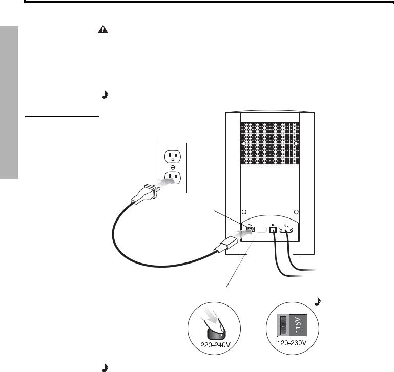
Connecting the power cord
CAUTION: For dual voltage models only, be sure to set the dual voltage switch on the back of the Acoustimass® module to the appropriate voltage for your area (115V or 230V) before connecting to power. If you are not sure about the proper voltage for your area, consult your local electrical authorities.
1.Insert the small connector end of the power cord into the AC INPUT connector on the Acoustimass module (Figure 20).
2.Insert the large end of the cord into an AC power (mains) outlet.
Note: On 220-240V models only, turn the Acoustimass module POWER switch to on (l).
Figure 20
Connecting to power
AC input jack 
AC power switch
 Note: Provided only on 220-240V rated systems.
115/230V selection switch
Note: Provided only on 115/230V dual voltage rated systems.
Note: Bose recommends using a safety agency-approved surge protector on all electronic equipment. Voltage variations and spikes can damage electronic components in any system. A quality suppressor can eliminate the vast majority of failures attributed to surges and may be purchased at electronics stores.
24
EnglishDansk |
DeutschEspañol |
FrançaisItliano |
Nederlands |
Svenska |
SYSTEM SETUP
Checking your system setup
Follow these steps when turning on your system for the first time. Be sure to perform step 4 and play the setup DVD. The setup DVD can help you verify that you set up your system correctly for proper sound performance.
1.Check the following before you continue:
•All cables are connected for the setup you chose.
•The batteries were installed in the remote control.
•The power cord was installed and plugged into a live AC receptacle.
2.Turn on your TV. Use the remote control that came with your TV.
3.Using your TV remote, select the video input on your TV that connects to the video output of the media center.
Name TV video input used:
•The method of selecting the right video input depends on your TV. Refer to your TV owner’s guide for help.
4.Play the 3•2•1 setup DVD.
A.Turn on your 3•2•1 system. Point the 3•2•1 remote control at the media center and press On-Off.
B.Press Eject on the media center control panel.
C.Insert the DVD setup disc into the disc tray.
D.Press Eject again to close the tray. The DVD will automatically begin to play. If it does not, press the play button (  ).
).
5.Turn off the TV speakers.
•Refer to your TV owner’s guide for help.
•If your TV does not have an option to turn off the internal speakers, you may need to adjust both the 3•2•1 system volume and your TV volume until you find a level that produces the desired sound.
•In some TVs, when the internal speakers are turned off, you may need to raise the TV’s volume level by 75% to 100% in order to hear audio from the 3•2•1 home entertainment system. See your TV owner’s guide for help.
Note: Be sure to play the setup DVD, included in the carton with your system, as soon as all the connections are completed. This will help you verify the connections you have made and confirm proper sound performance.
ETUPS YSTEMS
25
SYSTEM CONTROLS AND INDICATORS
Svenska |
Nederlands |
FrançaisItliano |
DeutschEspañol |
EnglishDansk |
SYSTEM CONTROLS AND INDICATORS
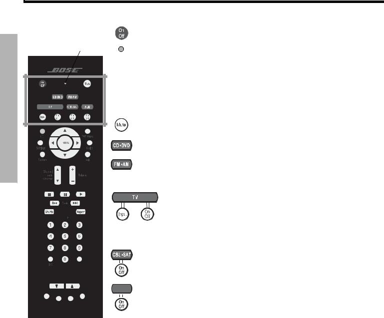
Remote control
Remote |
• Turns the system on or off. |
status |
|
LED |
Status LED: |
|
• Remains off (unlit) during normal operation.
• Remains on during setup mode. Turns off briefly with each key press.
• Blinks rapidly eight times if the wrong key is pressed during setup or if an unavailable device code is entered.
• After ten seconds of no key presses, blinks rapidly eight times and the remote exits the setup mode.
• Silences or restores the sound from the current source.
• Selects the built-in CD/DVD player and turns the system on.
• Selects the built-in tuner and turns the system on to the previously selected FM/ AM station.
• Switches between FM and AM when the tuner is selected.
• TV: Turns your system on and selects the TV input as the sound source.
• Input: Changes the external input to your TV. For example, your TV might have two external inputs where one is connected to your cable box and the other to your VCR. Pressing this button alternates between the cable box and the VCR.*
• On/Off: Turns your TV on and off.*
• CBL SAT: Turns your system on and selects the CBL SAT input as the sound source.
• On/Off: Turns your cable/satellite box on or off.*
AUX • AUX: Turns your system on and selects the AUX input as the sound source.
• On/Off: Turns a VCR or DVR that is connected to the AUX jack on or off.*
*Requires special remote settings. See “Setting up your remote to control other audio/video devices” on page 30.
26
 Loading...