

Bosch ROS65VC-5, ROS65VC-6 Owner’s Manual

BM 2609932778 04-11:BM 2609932778 04-11.qxp 3/31/11 7:40 AM Page 1
IMPORTANT: IMPORTANT : IMPORTANTE:
Read Before Using Lire avant usage Leer antes de usar
Operating/Safety Instructions
Consignes de fonctionnement/sécurité
Instrucciones de funcionamiento y seguridad
ROS65VC
Call Toll Free for
Consumer Information
& Service Locations
Pour obtenir des informations
et les adresses de nos centres
de service après-vente,
appelez ce numéro gratuit
Llame gratis para
obtener información
para el consumidor y
ubicaciones de servicio
1-877-BOSCH99 (1-877-267-2499) www.boschtools.com
For English Version Version française Versión en español
See page 2 Voir page 14 Ver la página 26

BM 2609932778 04-11:BM 2609932778 04-11.qxp 3/31/11 7:40 AM Page 2
General Power Tool Safety Warnings
WARNING
!
Read all safety warnings and all instructions. Failure to follow the warnings
and instructions may result in electric shock, fire and/or serious injury.
SAVE ALL WARNINGS AND INSTRUCTIONS FOR FUTURE REFERENCE
The term “power tool” in the warnings refers to your mains-operated (corded) power tool or
battery-operated (cordless) power tool.
Work area safety
Keep work area clean and well lit. Cluttered
or dark areas invite accidents.
Do not operate power tools in explosive
atmospheres, such as in the presence of
flammable liquids, gases or dust. Power
tools create sparks which may ignite the dust
or fumes.
Keep children and bystanders away while
operating a power tool. Distractions can
cause you to lose control.
Electrical safety
Power tool plugs must match the outlet.
Never modify the plug in any way. Do not
us e a ny adapter pl ug s with earthe d
(grounded) power tools. Unmodified plugs
and matching outlets will reduce risk of electric
shock.
Avoid body contact with earthed or grounded
surfaces such as pipes, radiators, ranges
and refrigerators. There is an increased risk
of electric shock if your body is earthed or
grounded.
Do not expose power tools to rain or wet
conditions. Water entering a power tool will
increase the risk of electric shock.
Do not abuse the cord. Never use the cord
for carrying, pulling or unplugging the power
tool. Keep cord away from heat, oil, sharp
edges or moving parts. Damaged or entangled
cords increase the risk of electric shock.
When operating a power tool outdoors,
use an extension cord suitable for outdoor
use. Use of a cord suitable for outdoor use
reduces the risk of electric shock.
If operating the power tool in damp locations
is unavoidable, use a Ground Fault Circuit
Interrupter (GFCI) protected supply. Use of
an GFCI reduces the risk of electric shock.
Personal safety
Stay alert, watch what you are doing and
us e co mmon sense w hen opera ting a
power tool. Do not use a power tool while
you are tired or under the influence of drugs,
alcohol or medication. A moment of inattention
while operating power tools may result in
serious personal injury.
Use personal protective equipment. Always
wear eye protection. Protective equipment
such as dust mask, non-skid safety shoes, hard
hat, or hearing protection used for appropriate
conditions will reduce personal injuries.
Prevent unintentional starting. Ensure the
sw itch is in th e o ff-po sitio n b efore
connecting to power source and / or battery
pa ck, picki ng up or carrying the t ool.
Carrying power tools with your finger on the
switch or energizing power tools that have the
switch on invites accidents.
Remove any adjusting key or wrench before
turning the power tool on. A wrench or a
key left attached to a rotating part of the
power tool may result in personal injury.
Do not overreach. Keep proper footing and
balance at all times. This enables better
co ntrol of the power to ol in unexpe ct ed
situations.
Dress properly. Do not wear loose clothing
or jewelry. Keep your hair, clothing and
gloves away from moving parts. Loose
clothes, jewelry or long hair can be caught in
moving parts.
If devices are provided for the connection
of dust extraction and collection facilities,
ensure these are connected and properly
used. Use of dust collection can reduce dust-
related hazards.
Power tool use and care
Do not forc e the power to ol. Use the
correct power tool for your application. The
correct power tool will do the job better and
safer at the rate for which it was designed.
Do not use the power tool if the switch does
not turn it on and off. Any power tool that
ca nn ot be co nt ro ll ed wi th th e swi tc h is
dangerous and must be repaired.
-2-

BM 2609932778 04-11:BM 2609932778 04-11.qxp 3/31/11 7:40 AM Page 3
Disconnect the plug from the power source
and/or the battery pack from the power tool
before making any adjustments, changing
accessories, or storing power tools. Such
preventive safety measures reduce the risk of
starting the power tool accidentally.
Store idle power tools out of the reach of
children and do not allow persons unfamiliar
with the power tool or these instructions to
operate the power tool. Power tools are
dangerous in the hands of untrained users.
Maintain power tools. Check for misalignment
or binding of moving parts, breakage of
parts and any other condition that may
affect the power tool’s operation. If damaged,
have the power tool repaired before use.
Ma ny acci de nt s ar e ca us ed by poorly
maintained power tools.
Safety Rules for Random Orbital Sanders
Keep cutting tools sharp and clean. Properly
maintained cutting tools with sharp cutting
edges are less likely to bind and are easier to
control.
Use the power tool, accessories and tool
bits etc. in accordance with these instructions,
taking into account the working conditions
and the work to be performed. Use of the
power tool for operations different from those
intended could result in a hazardous situation.
Service
Have your power tool serviced by a qualified
re pa ir person u sing on ly identical
replacement parts. This will ensure that the
safety of the power tool is maintained.
Hold power tools by insulated gripping
surfaces when performing an operation
where the cutting tool may contact hidden
wiring or it own cord. Contact with a "live"
wire will make exposed metal parts of the tool
"live" and shock the operator.
Unplug the san de r bef or e chang in g
accessories. Accidental start-ups may occur
if sander is plugged in while changing an
accessory.
If your tool is equipped with a dust bag,
empty it frequently and after completion
of sanding. Be extremely careful of dust
disposal, materials in fine particle form may
be explosive. Do not throw sanding dust on
an open fire. Spontaneous combustion, may
in time, result from mixture of oil or water
with dust particles.
Always wear eye protection and a dust
mask for dusty applications a nd when
sanding overhead. Sanding particles can be
absorbed by your eyes and inhaled easily
and may cause health complications.
Do not wet sand with this sander. Liquids
entering the motor housing is an electrical
shock hazard.
Do not use PS A pad on rand om orb it
sanders whose sp eed ex ce eds
12,000/ mi n. Exceedi ng t he maximum
operating speed of pad may cause pad to
rupture or fly apart during use striking user or
bystanders.
Do not use sandpaper intended for larger
sanding pads. Larger sandpaper will extend
beyond the sanding pad causing snagging,
tearing of the paper or kick-back. Extra paper
extending beyond the sanding pad can also
cause serious lacerations.
Clamp o r secure wo rkpiece w he n
sanding. Clamping the workpiece prevents
it from being ejected from under the sander
and leaves both hands to control the tool.
Keep the cord away from the spinning
pad and sandpaper. The cord can become
entangled with the pad.
-3-

BM 2609932778 04-11:BM 2609932778 04-11.qxp 3/31/11 7:40 AM Page 4
Additional Safety Warnings
GFCI and personal protection devices like
electrician’s rubber gloves and footwear will
further enhance your personal safety.
Do not use AC only rated tools with a DC
power supply. While the tool may appear to
work, the electrical components of the AC
rated tool are likely to fail and create a hazard
to the operator.
Keep handles dry, clean and free from oil
and grease. Slippery hands cannot safely
control the power tool.
Develop a periodic maintenance schedule
for your tool. When cleaning a tool be
careful not to disassemble any portion of
th e tool sinc e interna l wires may be
misplaced or pinched or safety guard return
sp rings may be improperly moun ted.
Certain cleaning agents such as gasoline,
carbon tetrachloride, ammonia, et c. may
damage plastic parts.
Risk of injury to user. The power cord must only
be serviced by a Bosch Factory Service Center
or Autho rized Bosch Service Station.
!
WARNING
drilling, and other construction activities
contains chemicals known to cause cancer,
birth defects or other reproductive harm.
Some examples of these chemicals are:
• Lead from lead-based paints,
• Crystalline silica from bricks and cement and
other masonry products, and
• Arsenic and chromiu m from chemicallytreated lumber.
Yo ur ri sk from these expo su re s var ie s,
depending on how often you do this type of
work. To reduce your exposure to these
chemicals: work in a well ventilated area, and
work with approved safety equipment, such as
those dust masks that are specially designed
to filter out microscopic particles.
Some dust created by power
sanding, sawing, grinding,
-4-

0
BM 2609932778 04-11:BM 2609932778 04-11.qxp 3/31/11 7:40 AM Page 5
Symbols
IMPORTANT: Some of the following symbols may be used on your tool. Please study them
and learn their meaning. Proper interpretation of these symbols will allow you to operate the
tool better and safer.
Symbol Name Designation/Explanation
V Volts Voltage (potential)
A Amperes Current
Hz Hertz Frequency (cycles per second)
W Watt Power
kg Kilograms Weight
min Minutes Time
s Seconds Time
Diameter Size of drill bits, grinding wheels, etc.
n
0
n Rated speed Maximum attainable speed
.../min Revolutions or reciprocation Revolutions, strokes, surface speed,
0 Off position Zero speed, zero torque...
1, 2, 3, ... Selector settings Speed, torque or position settings.
I, II, III, Higher number means greater speed
No load speed Rotational speed, at no load
per minute orbits etc. per minute
Infinitely variable selector with off Speed is increasing from 0 setting
Arrow Action in the direction of arrow
Alternating current Type or a characteristic of current
Direct current Type or a characteristic of current
Alternating or direct current Type or a characteristic of current
Class II construction Designates Double Insulated
Construction tools.
Earthing terminal Grounding terminal
Warning symbol Alerts user to warning messages
Li-ion RBRC seal Designates Li-ion battery recycling
program
Ni-Cad RBRC seal Designates Ni-Cad battery recycling
program
Read manual symbol Alerts user to read manual
Wear eye protection symbol Alerts user to wear eye protection
-5-
BM 2609932778 04-11:BM 2609932778 04-11.qxp 3/31/11 7:40 AM Page 6
Symbols (continued)
IMPORTANT: Some of the following symbols may be used on your tool. Please study them
and learn their meaning. Proper interpretation of these symbols will allow you to operate the
tool better and safer.
This symbol designates that this tool is listed by Underwriters Laboratories.
This symbol designates that this tool is recognized by Underwriters Laboratories.
This symbol designates that this tool is listed by Underwriters Laboratories,
to United States and Canadian Standards.
This symbol designates that this tool is listed by the Canadian Standards
Association.
This symbol designates that this tool is listed by the Canadian Standards
Association, to United States and Canadian Standards.
This symbol designates that this tool is listed by the Intertek Testing
Services, to United States and Canadian Standards.
This symbol designates that this tool complies to NOM Mexican Standards.
-6-
BM 2609932778 04-11:BM 2609932778 04-11.qxp 3/31/11 7:40 AM Page 7
Functional Description and Specifications
!
WARNING
Di sc on nect the pl ug from the power source be fore makin g any
assembly, adjustments or changing accessories. Such preventive safety
measures reduce the risk of starting the tool accidentally.
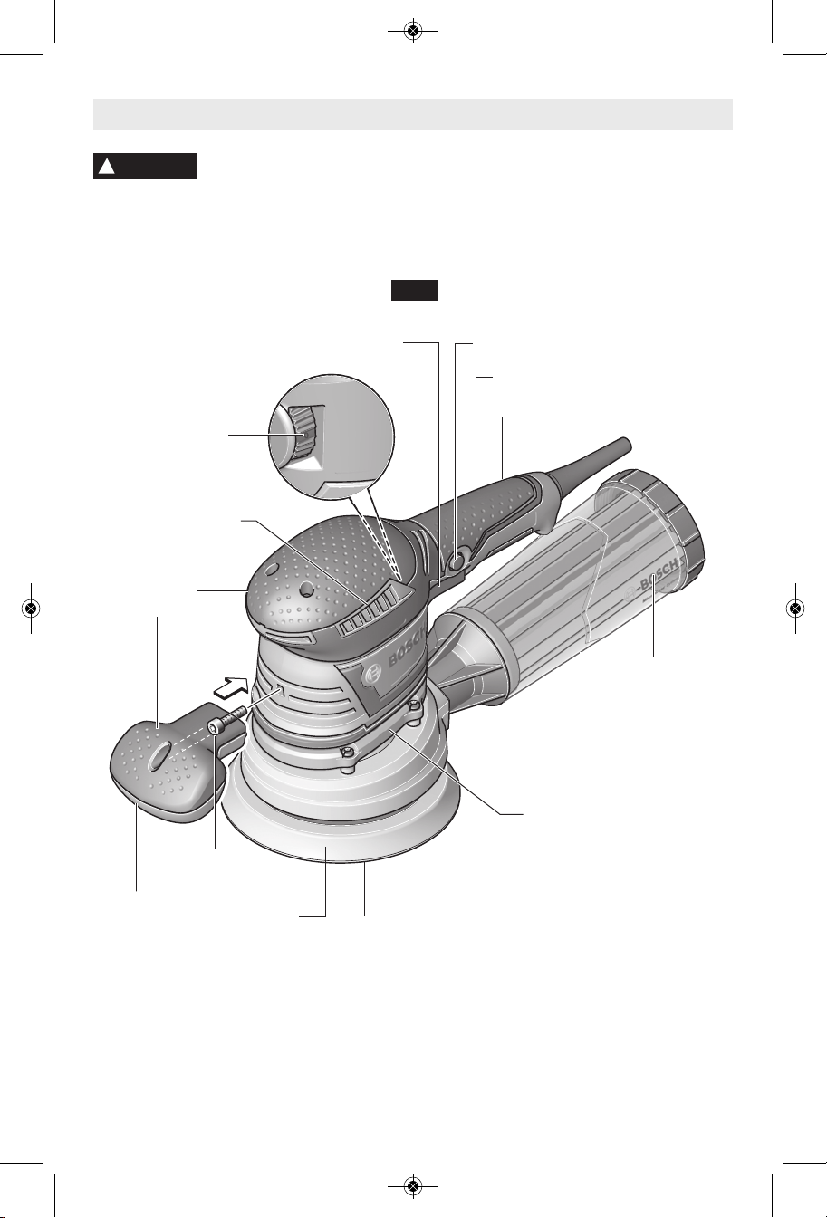
Random Orbit Sander
FIG. 1
TRIGGER SWITCH
VARIABLE SPEED
DIAL
VENTILATION
OPENINGS
RUBBERIZED
GRIP
“LOCK-ON” BUTTON
REAR HANDLE
RUBBERIZED GRIP
CORD
MICROFILTER
FRONT
HANDLE
DUST
CANISTER
VIBRATION CONTROL
SUSPENSION SYSTEM
Suspension system separates
housing and grip areas above this
point from motor housing and
SCREW
BACKING PAD
ABRASIVE DISC
sanding mechanism for low
vibration and maximum comfort
MAXIMUM CAPACITIES
Pad diameter 5" (125 mm) or 6" (150 mm)
Abrasive diameter 5" (125 mm) or 6" (150 mm)
NOTE: For tool specifications refer to the nameplate on your tool.
-7-
BM 2609932778 04-11:BM 2609932778 04-11.qxp 3/31/11 7:40 AM Page 8
Assembly
BACKING PAD INSTALLATION
The random orbit sander is equipped with a
backing pad of soft hardness, which is suitable
for general service. Hard and extra-soft pads
ar e av ailab le for oth er p urpos es, and in
general are used as follows;
Extra soft pad - Polishing or sanding large or
curved surfaces.
Soft pad - All purpose general sanding and
polishing.
Hard pad - Heavy sanding on flat surfaces,
especially with coarser abrasives.
This sander is unique in that it can accept
either 5" or 6" (Bosch) pads.
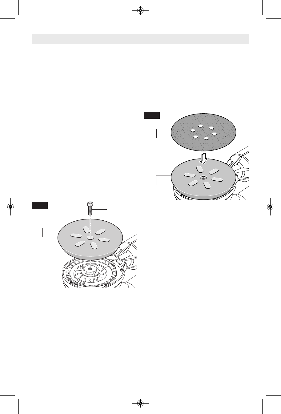
To change backing pad, hold pad firmly and
remove the screw using a 5 mm hex wrench
that secures the backing pad and remove old
pad. Align new pad over drive gear on drive
spindle. Attention: always be sure the teeth
on the drive gear engage into the openings on
the backing pad. Replace screw and securely
tighten. Damaged or worn backing pads must
be replaced immediately (Fig. 2).
FIG. 2
BACKING
PAD
SCREW
INSTALLING ACCESSORIES
The random orbit sander uses hook-and-loop
backed accessories, which firmly grip the pad
when applied with moderate pressure. To
change the accessory, merely peel off the old
ac cessory, rem ove du st from the pad if
necessary, and press the new accessory in
place (Fig. 3). Be sure to align the sanding
disc holes with the holes in the backing pad to
allow the dust extraction system to function.
FIG. 3
ABRASIVE
DISC
BACKING
PAD
After considerable service the pad surface will
become worn, and the pad must be replaced
when it no longer offers a firm grip. If you are
experiencing premature wearout of the pad
hooks, it may be due to pressure being applied
to the tool during operation.
DRIVE
GEAR
-8-
2
1
BM 2609932778 04-11:BM 2609932778 04-11.qxp 3/31/11 7:40 AM Page 9
Your tool is equipped with an integrated backing
pad damper ring. This damper reduces the
no-load speed, which helps pre vent swirl
marks on the workpiece surface and provides
uniform finishing.
NOTE: If you notice steadily increasing noload speed, this indicates that the damper ring
is worn and needs to be replaced.
To replace damper ring, remove backing pad
as described in “Backing Pad Installation” and
remove worn damper ring by pulling firmly out
of locating groove. Align notch on damper ring
with locating tab on shroud and depress ring
with thumbs until shroud seats into groove
completely around ring (Fig. 4).
Re -attach bac king pa d as desc ri bed in
“Backing Pad Installation”
IMPORTANT: Ring should not have bends or
ripples when correctly seated.
BACKING PAD DAMPER
Dust Collection
MICROFILTER DUST CANISTER
The integral dust extraction system collects
sanding dust in canister supplied with your
sander. For maximum efficiency, the dust
canister should be emptied frequently during
operation.
WARNING
!
frequently, after completion of sanding and
before storing the sander. Be extremely
careful of dust disposal, materials in fine
particle form may be explosive. Do not throw
sanding dust on an open fire. Combustion from
FIG. 5
Your tool is equipped with
a dust canister, empty it
FIG. 4
LOCATING
TAB
mixture of varnishes, lacquers, polyurethane,
oil or water with dust particles can occur if
there is a static discharge, spark introduced in
the box, or excessive heat.
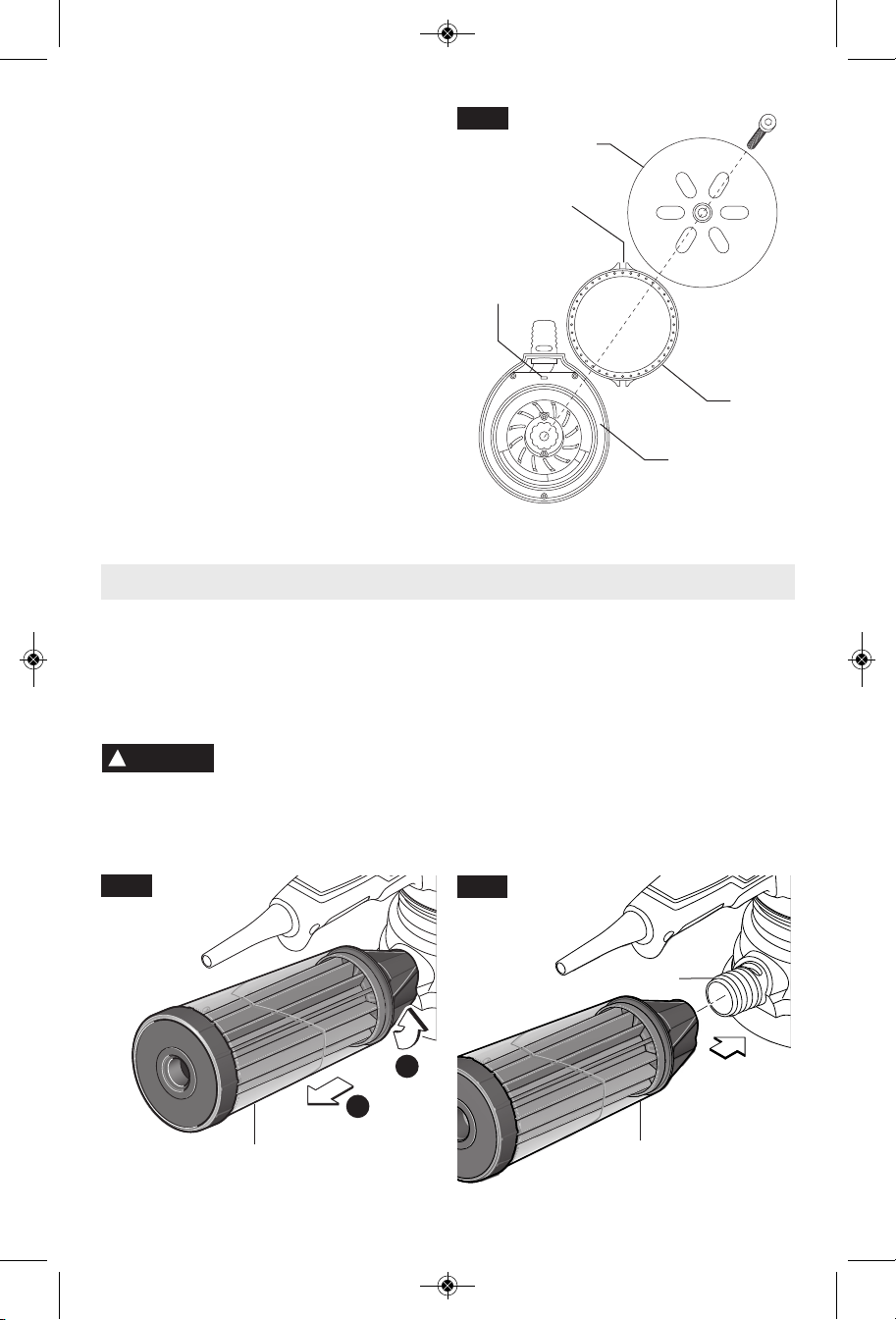
To remove dust canister: Twist the dust
canister and simply pull away from the tool
(Fig. 5).
To install dust canister: align dust port with
hole in canister and push canister onto tool
until it locks into place (Fig. 6).
BACKING
PAD
NOTCH
DAMPER
RING
SHROUD
REMOVING AND INSTALLING
DUST CANISTER
FIG. 6
DUST
CANISTER
DUST PORT
DUST
CANISTER
-9-
2
1
BM 2609932778 04-11:BM 2609932778 04-11.qxp 3/31/11 7:40 AM Page 10
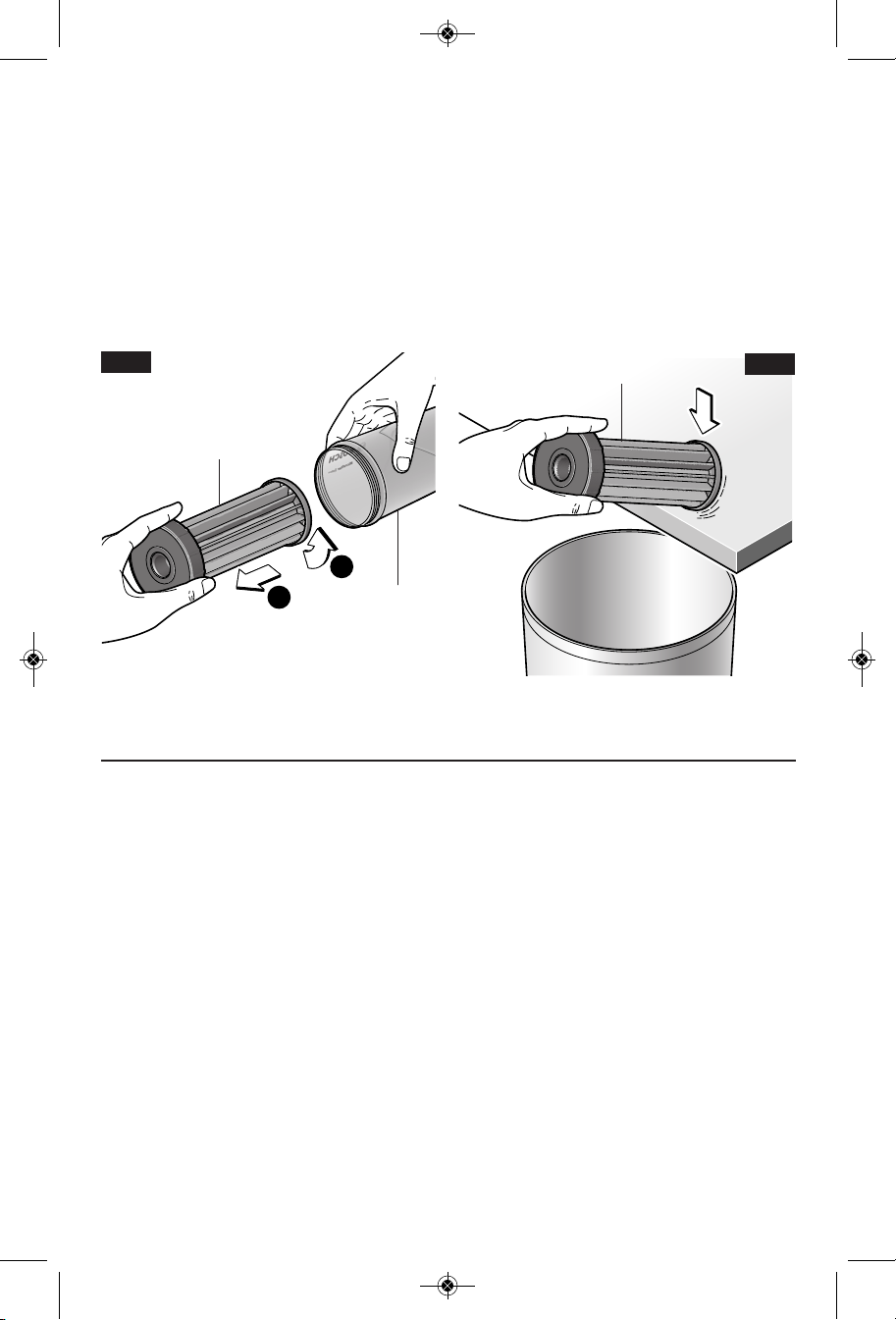
CLEANING AND EMPTYING THE
DUST CANISTER
The dust canister is transparent which will
allow you to easily see when empting and
cleaning is requires.
To empty dust the canister: screw off and
remove microfilter from the dust canister.
Empty dust canister (Fig. 7).
It is recommended to loosen dust from the
microfilter by gently striking it against a solid
surface (Fig. 8).
FIG. 7
MICROFILTER
DUST
CANISTER
Knock excess dust out of the microfilter, or
remove dust with your fingers or a soft brush.
You may notice that all the dust may not come
out of the canister. This will not affect sanding
performance but will reduce dust collection
efficiency.
NOTE: Do not wash the microfilter with soap
and water. Dust may become more firmly
lodged in the pores, which will reduce dust
collection, and damage the micro filter.
To ensure optimum dust extraction, empty and
clean the canister and microfilter frequently.
MICROFILTER
FIG. 8
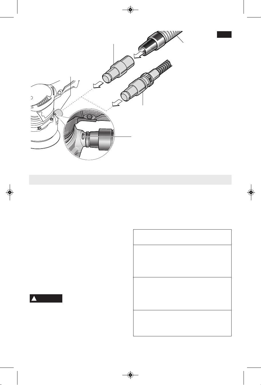
ATTACHING VACUUM HOSE
When the canister is removed from the tool, an
(optional) vacuum hose accessory can be
attached to the dust port. To use this feature,
attach vacuum hose (optional accessory) to
dust port, then connect opposite end of the
vacuum hose to a shop vacuum cleaner.
The VAC024 vacuum hose adapter is included
for connection of this tool to a 1-1/4" or 1-1/2"
vacuum hose (Fig. 9).
Mount the vacuum hose onto the dust port in
such a manner that the open slot on the dust
port remains open. This prevents the tool from
adhering to the workpiece during sanding
operation and improves the surface quality.
When using a vacuum hose with this sander
SUCTION CONTROL
the amount of suction can be adjusted by
sliding the hose over or off the open slot in the
hose port area on the sander.
The vacuum cleaner must be suitable for the
material being sanded.
When vacuuming dry dust that is especially
detrimental to health or may be carcinogenic,
use a special vacuum cleaner.
When sanding on vertical surfaces, hold the
power tool in such a manner that the vacuum
hose faces downward.
-10-
BM 2609932778 04-11:BM 2609932778 04-11.qxp 3/31/11 7:40 AM Page 11
VAC024
DUST
PORT
BOSCH
VACUUM HOSE
SUCTION
CONTROL SLOT
FIG. 9
1-1/4”
OR
1-1/2” HOSE
Operating Instructions
TRIGGER "ON-OFF" SWITCH
To turn the tool "ON" squeeze the trigger
switch. To turn the tool "OFF", release the
trigger switch, which is spring loaded and will
return to the "OFF" position automatically
(Fig. 1).
To increase switch life, do not turn switch on
and off while tool is under load.
The "Lock-ON" button, located near the trigger
allows for continuous operation at maximum
OPM without holding the trigger (Fig. 1).
TO LOCK TRIGGER "ON": squeeze trigger,
depress button and release trigger.
TO UNLOCK THE TRIGGER: squeeze trigger
and release it without depressing the "LockON" button.
!
the trigger can not be released.
VARIABLE SPEED WITH DIAL SETTING
Your sander is also equipped with a variable
speed dial (Fig. 1). The sander's orbital pad
speed can be preset from zero to maximum
nameplate OPM by rotating the dial in the
"LOCK-ON" BUTTON
WARNING
If the “ Lock-ON” but ton is
continuously being depressed,
housing. The dial may be set on or between
any of six positions (1=low through 6=high).
The following table may be used as a general
guide for abrasive and backing pad selection,
but the best results will be obtained by sanding
a test sample of the workpiece first.
Switch Backing Grit
Material setting pad size
rough/finish rough/finish
woods:
softwoods 4 / 6 extra soft 60 / 240
hardwoods 4 / 6 soft 60 / 180
veneers 4 soft 240 / 320
metals:
steel 4 soft 60 / 240
stainless 4 soft 120 / 240
aluminum 4/ 6 soft 80 / 240
rust spots 6 extra soft 60 / 120
paintwork:
sanding 2 / 3 soft 180 / 400
scratches 4 / 6 hard 120 / 240
stripping 4 soft 40/60 /80
-11-

BM 2609932778 04-11:BM 2609932778 04-11.qxp 3/31/11 7:40 AM Page 12
Your sander is equipped with a removable
FRONT HANDLE
front handle when sanding in tight quarters. To
remove handle, remove screw with 5 mm hex
wrench. Always reinstall handle for normal
operation (Fig. 1).
Tool Tips
SELECTING SANDING DISCS
Open-coat aluminum oxide sanding discs are
recommended for most wood or metal sanding
applications, as this synthetic material cuts
quickly and wears well. Some applications,
such as plastics, glass, or stone require silicon
carbide discs, which have a very sharp cutting
edge. For best results, use Bosch sanding
an d po lishing acc essorie s, w hich are o f
superior quality and are carefully selected to
produce professional quality results with your
sander.
START OF SANDING
With the workpiece firmly secured, place the
pad on the work surface, then switch the tool
on. DO NOT apply excessive pressure as this
will slow the pad action, and DO NOT start the
tool and bring it up to speed before applying to
the work; swirl marks will result in either case.
SANDING ACTION
This sander has optimized random sanding
action. The pad orbits and rotates freely,
duplicating natural hand sanding action for
aggressive stock removal and smooth, wellblended surface finish. The orbit offset for this
tool is 2 mm (5/64")
In general, higher speeds will give the best
results. If faster removal is desired, DO NOT
APPLY PRESSURE ON THE TOOL; use a
coarser grade of abrasive. Move the sander in
long sweeping strokes, parallel to the grain
using some late ral motion to ove rlap the
strokes by as much as 75%. The random orbit
action allows cross-grain sanding, but be
careful not to tilt the sander near edges, or
undesirable rounding may result.
SANDING SEQUENCE
If the surface is rough, begin with coarser grits
and then complete the surfacing with medium
and fine abrasives. Because the random orbit
action is so effective, it is often possible to
begin sanding with a medium grit disc and go
directly to fine finishing. To avoid uneven
results, do not skip more than one grit size
Depending on the task, you may grip the rear
handle alone, the rear handle and the front
handle, or the rear handle and the top of the
er gonomically contoured soft grip motor
housing, which is designed for that purpose.
when going from coarser to finer, and do not
sand in one area for too long.
REMOVAL OF SANDER
To help prevent swirl marks when the job is
completed, gently lift the tool from the work
surface, then switch the tool off.
POLISHING
For most polishing, the extra-soft backing pad
will give the best results. The random orbit
sander may be fitted with an optional foam
buffing pad or polishing bonnet to polish or
remove scratches from painted or finished
surfaces, plastics, and even glass. The tool is
operated in much the same way as when
sanding, but the following points should be
observed;
Apply the compound to the surface, and use
the sponge applicator pad with light pressure
and a circular motion to remove scratches and
restore weathered finishes. Use only as much
co mpound a s necess ary, and clean th e
sponge frequently during use.
When initial polishing is completed, wipe away
any excess compound with a soft towel, and
then polish the surface to its final finish with the
polishing bonnet. Use smooth overlapping
strokes for best results.
It is important to note that the orbit speed of
the random orbit sander is not the same as the
RPM of a standard right-angle polisher. The
random orbit action is much like a powerful
hand polishing action, and therefore does not
have the high speeds at the edge of the pad
which can burn the work surface. For this
reason, it is possible to select a higher OPM
fo r the random o rbit sander t ha n the
recommended RPM for a standard polisher.
Practice on a hidden area or test surface until
you have determined the tool is suitable for
your polishing application.
Clean the buffing pad and polishing bonnet
with mild detergents and warm water. DO
NOT use solvents.
-12-
 Loading...