

Page 1
OBJ_BUCH-1563-002.book Page 1 Wednesday, March 28, 2012 1:05 PM
Robert Bosch GmbH
Power Tools Division
70745 Leinfelden-Echterdingen
Germany
www.bosch-pt.com
PTA 2000
1 619 929 K24 (2012.03) PS / 77 UNI
de Originalbetriebsanleitung
en Original instructions
fr Notice originale
es Manual original
pt Manual original
it Istruzioni originali
nl O orspronkelijke
gebruiksaanwijzing
da Original brugsanvisning
sv Bruksanvisning i original
no Original driftsinstruks
fi Alkuperäiset ohjeet
el Рсщфьфхрп пдзгйюн чсЮузт
tr Orijinal işletme talimat
pl Instrukcja oryginalna
cs Původní návod k používání
sk Pôvodný návod na použitie
hu Eredeti használati utasítás
ru Оригинальное руководство по
эксплуатации
uk Ориг³нальна ³нструкц³я з
експлуатац³¿
ro Instrucţiuni originale
bg Оригинална инструкция
sr Originalno uputstvo za rad
sl Izvirna navodila
hr Originalne upute za rad
et Algupärane kasutusjuhend
lv Instrukcijas oriģinālvalodā
lt Originali instrukcija
Page 2

OBJ_BUCH-1563-002.book Page 2 Wednesday, March 28, 2012 1:05 PM
2 |
Deutsch . . . . . . . . . . . . . . . . . . . . . . . . . . . . . . . . . . . . . . . . . Seite 9
English . . . . . . . . . . . . . . . . . . . . . . . . . . . . . . . . . . . . . . . . . . Page 11
Français . . . . . . . . . . . . . . . . . . . . . . . . . . . . . . . . . . . . . . . . . Page 14
Español . . . . . . . . . . . . . . . . . . . . . . . . . . . . . . . . . . . . . . . . Página 17
Português. . . . . . . . . . . . . . . . . . . . . . . . . . . . . . . . . . . . . . . Página 20
Italiano . . . . . . . . . . . . . . . . . . . . . . . . . . . . . . . . . . . . . . . . . Pagina 22
Nederlands . . . . . . . . . . . . . . . . . . . . . . . . . . . . . . . . . . . . . Pagina 25
Dansk . . . . . . . . . . . . . . . . . . . . . . . . . . . . . . . . . . . . . . . . . . . Side 27
Svenska . . . . . . . . . . . . . . . . . . . . . . . . . . . . . . . . . . . . . . . . . Sida 29
Norsk . . . . . . . . . . . . . . . . . . . . . . . . . . . . . . . . . . . . . . . . . . . Side 32
Suomi. . . . . . . . . . . . . . . . . . . . . . . . . . . . . . . . . . . . . . . . . . . . Sivu 34
ЕллзнйкЬ. . . . . . . . . . . . . . . . . . . . . . . . . . . . . . . . . . . . . . . . УелЯдб 36
Türkçe . . . . . . . . . . . . . . . . . . . . . . . . . . . . . . . . . . . . . . . . . Sayfa 39
Polski . . . . . . . . . . . . . . . . . . . . . . . . . . . . . . . . . . . . . . . . . . Strona 42
Česky . . . . . . . . . . . . . . . . . . . . . . . . . . . . . . . . . . . . . . . . . . Strana 44
Slovensky. . . . . . . . . . . . . . . . . . . . . . . . . . . . . . . . . . . . . . . Strana 47
Magyar . . . . . . . . . . . . . . . . . . . . . . . . . . . . . . . . . . . . . . . . . . Oldal 49
Русский . . . . . . . . . . . . . . . . . . . . . . . . . . . . . . . . . . . . . Страница 52
Укра¿нська. . . . . . . . . . . . . . . . . . . . . . . . . . . . . . . . . . . . Стор³нка 54
Română . . . . . . . . . . . . . . . . . . . . . . . . . . . . . . . . . . . . . . . . Pagina 57
Български . . . . . . . . . . . . . . . . . . . . . . . . . . . . . . . . . . . Страница 59
Srpski. . . . . . . . . . . . . . . . . . . . . . . . . . . . . . . . . . . . . . . . . . Strana 62
Slovensko . . . . . . . . . . . . . . . . . . . . . . . . . . . . . . . . . . . . . . . Stran 64
Hrvatski . . . . . . . . . . . . . . . . . . . . . . . . . . . . . . . . . . . . . . Stranica 67
Eesti . . . . . . . . . . . . . . . . . . . . . . . . . . . . . . . . . . . . . . . . . Lehekülg 69
Latviešu . . . . . . . . . . . . . . . . . . . . . . . . . . . . . . . . . . . . . . Lappuse 71
Lietuviškai . . . . . . . . . . . . . . . . . . . . . . . . . . . . . . . . . . . . Puslapis 74
1 619 929 K24 | (28.3.12) Bosch Power Tools
Page 3
OBJ_BUCH-1563-002.book Page 3 Wednesday, March 28, 2012 1:05 PM
| 3
4
3
4
3
2
1
5
6
7
8
9
3x
M8 x 45
4x
1x
M8 x 55
4x
1x
M8 x 35
A
1
Bosch Power Tools 1 619 929 K24 | (28.3.12)
Page 4
OBJ_BUCH-1563-002.book Page 4 Wednesday, March 28, 2012 1:05 PM
4 |
B1
PPS 7S
M8 x 45
M8 x 45
M8 x 55
M8 x 45
9
9
1 619 929 K24 | (28.3.12) Bosch Power Tools
Page 5
OBJ_BUCH-1563-002.book Page 5 Wednesday, March 28, 2012 1:05 PM
| 5
9
9
Bosch Power Tools 1 619 929 K24 | (28.3.12)
Page 6
OBJ_BUCH-1563-002.book Page 6 Wednesday, March 28, 2012 1:05 PM
6 |
B2
PTS 10
M8 x 45
M8 x 45
M8 x 35
M8 x 45
9
9
1 619 929 K24 | (28.3.12) Bosch Power Tools
Page 7
OBJ_BUCH-1563-002.book Page 7 Wednesday, March 28, 2012 1:05 PM
| 7
9
9
Bosch Power Tools 1 619 929 K24 | (28.3.12)
Page 8
OBJ_BUCH-1563-002.book Page 8 Wednesday, March 28, 2012 1:05 PM
8 |
C
PPS 7S PTS 10
D2D1
2
10
1
D4D3
8
1 619 929 K24 | (28.3.12) Bosch Power Tools
Page 9
OBJ_BUCH-1563-002.book Page 9 Wednesday, March 28, 2012 1:05 PM
Deutsch | 9
Deutsch
Sicherheitshinweise
Allgemeine Sicherheitshinweise
Lesen Sie alle dem Arbeitstisch oder dem zu
montierenden Elektrowerkzeug beigefügten Warnhinweise und Anweisungen. Ver-
säumnisse bei der Einhaltung der Sicherheitshinweise und Anweisungen können
elektrischen Schlag, Brand und/oder schwere
Verletzungen verursachen.
Sicherheitshinweise für Arbeitstische
f Ziehen Sie den Stecker aus der Steckdose und/oder
entnehmen Sie den Akku vom Elektrowerkzeug, bevor
Sie Geräteeinstellungen vornehmen oder Zubehörteile
wechseln. Unbeabsichtigter Start von Elektrowerkzeugen
ist die Ursache einiger Unfälle.
f Bauen Sie den Arbeitstisch korrekt auf, bevor Sie das
Elektrowerkzeug montieren. Einwandfreier Aufbau ist
wichtig, um das Risiko eines Zusammenbrechens zu verhindern.
f Befestigen Sie das Elektrowerkzeug sicher am Arbeits-
tisch, bevor Sie es benutzen. Ein Verrutschen des Elek-
trowerkzeugs auf dem Arbeitstisch kann zum Verlust der
Kontrolle führen.
f Stellen Sie den Arbeitstisch auf eine feste, ebene und
waagerechte Fläche. Wenn der Arbeitstisch verrutschen
oder wackeln kann, können das Elektrowerkzeug oder das
Werkstück nicht gleichmäßig und sicher geführt werden.
f Überlasten Sie den Arbeitstisch nicht und verwenden
Sie diesen nicht als Leiter oder Gerüst. Überlastung
oder Stehen auf dem Arbeitstisch kann dazu führen, dass
sich der Schwerpunkt des Arbeitstischs nach oben verlagert und dieser umkippt.
f Achten Sie darauf, dass beim Transport und beim Ar-
beiten sämtliche Schrauben und Verbindungselemente fest angezogen sind. Lockere Verbindungen können
zu Instabilitäten und ungenauen Sägevorgängen führen.
f Montieren und demontieren Sie das Elektrowerkzeug
nur, wenn es in Transportstellung ist (Hinweise zur
Transportstellung siehe auch Betriebsanleitung des jeweiligen Elektrowerkzeugs). Das Elektrowerkzeug kann
sonst einen so ungünstigen Schwerpunkt haben, dass Sie
es nicht sicher halten können.
f Stellen Sie sicher, dass lange und schwere Werkstücke
den Arbeitstisch nicht aus dem Gleichgewicht bringen.
Lange und schwere Werkstücke müssen am freien Ende
unterlegt oder abgestützt werden (z.B. mit Hilfe der Rollenauflage PTA 1000 von Bosch).
f Bringen Sie beim Aufstellen oder Zusammenlegen des
Arbeitstisches ihre Finger nicht in die Nähe der Gelenkpunkte. Die Finger könnten eingequetscht werden.
Symbole
Die nachfolgenden Symbole können für den Gebrauch Ihre s
Arbeitstisches von Bedeutung sein. Prägen Sie sich bitte die
Symbole und ihre Bedeutung ein. Die richtige Interpretation
der Symbole hilft Ihnen, den Arbeitstisch besser und sicherer
zu gebrauchen.
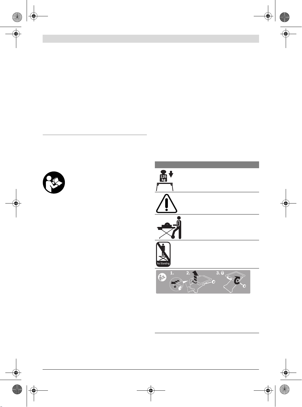
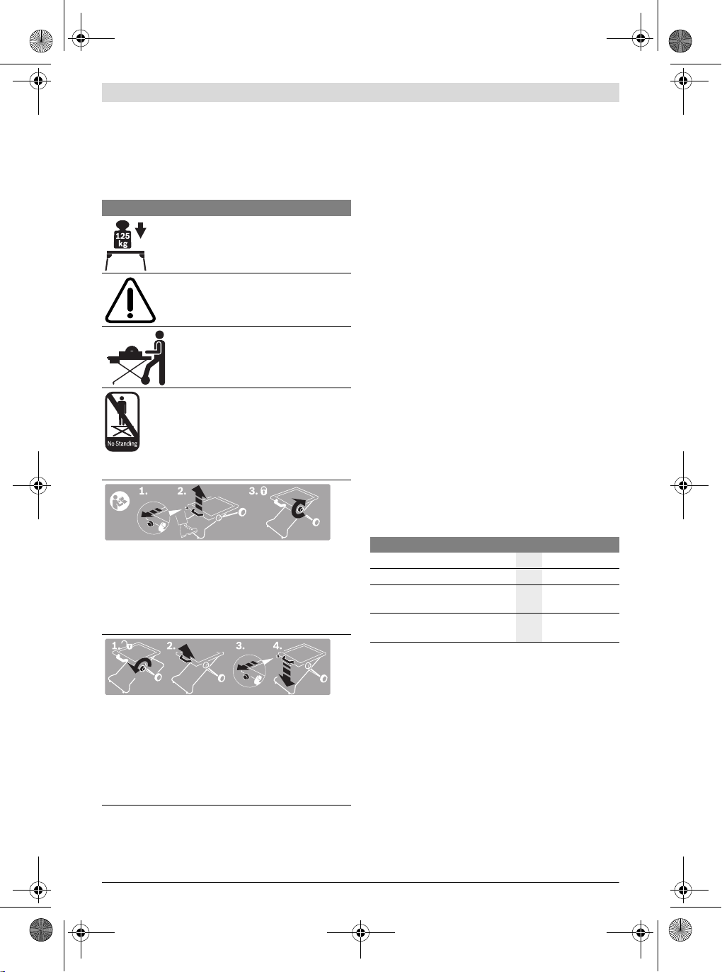
Symbol Bedeutung
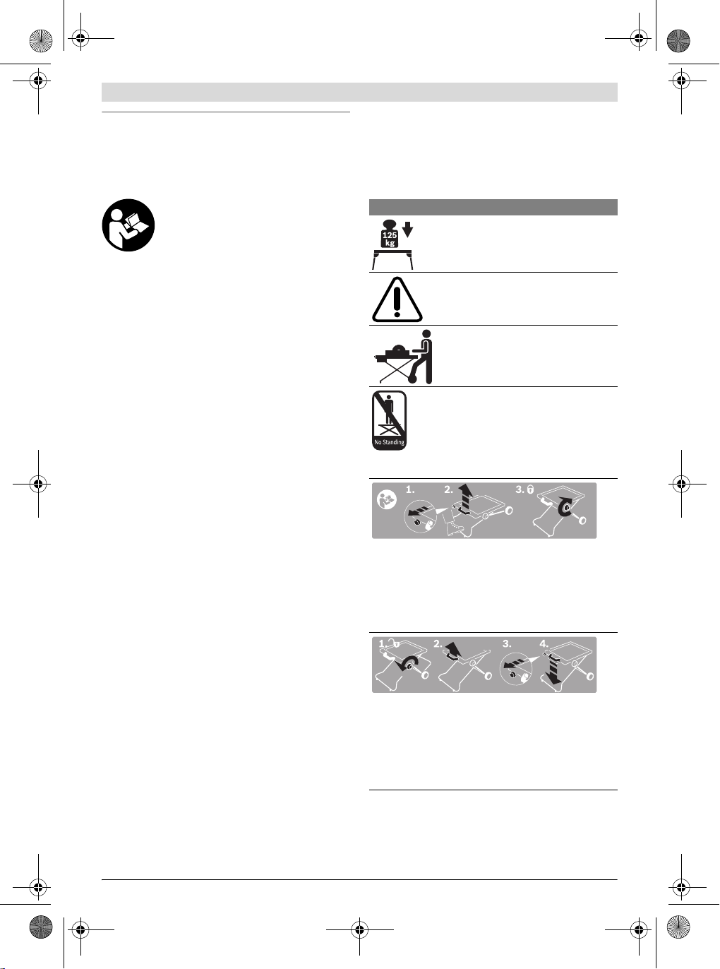
Die maximale Tragfähigkeit (Elektrowerkzeug + Werkstück) des Arbeitstisches beträgt 125 kg.
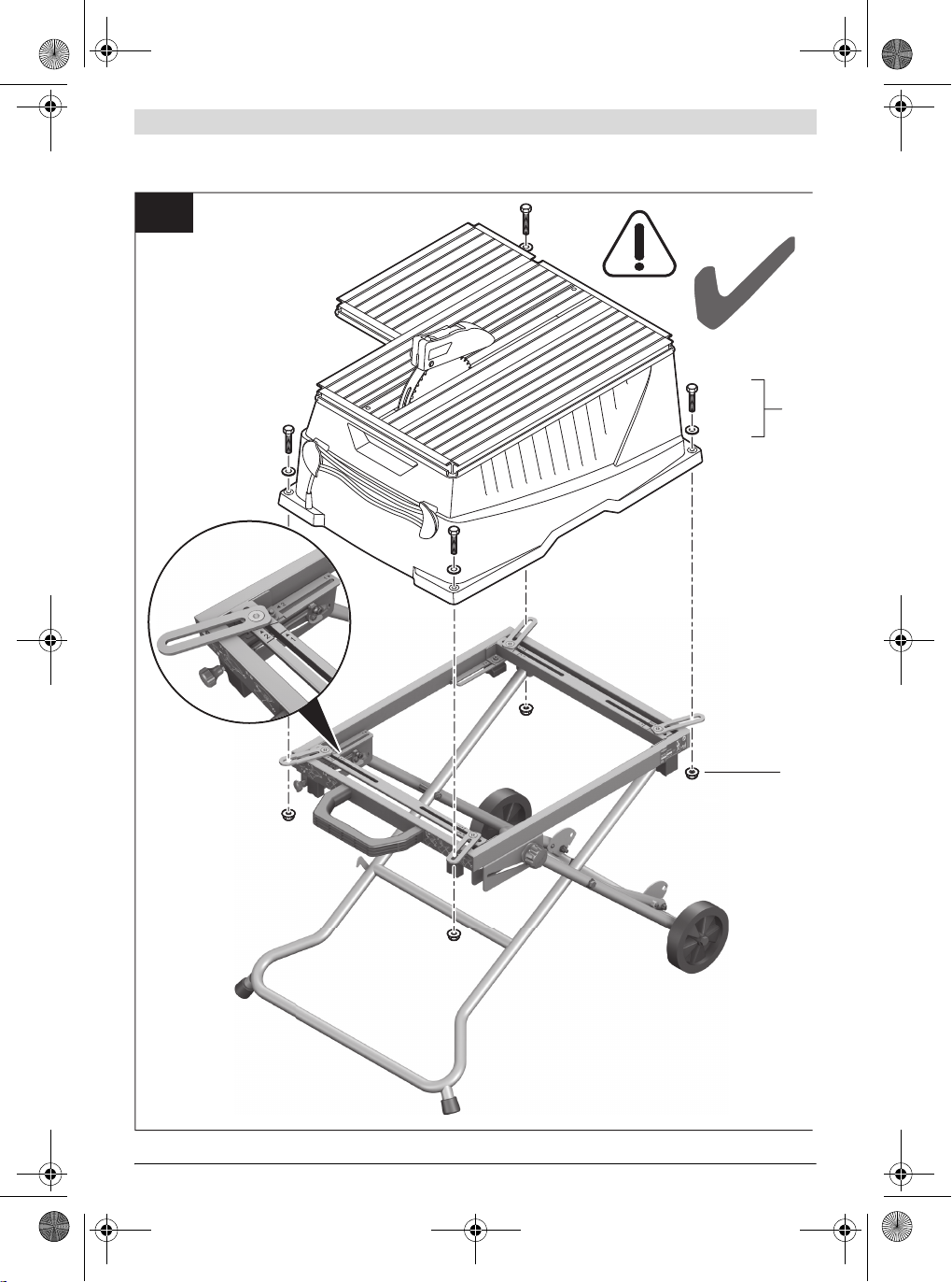
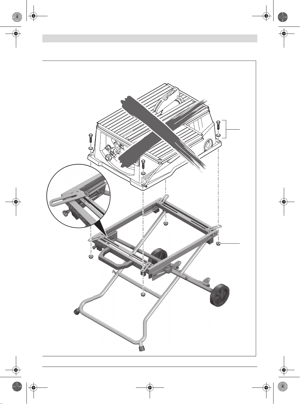
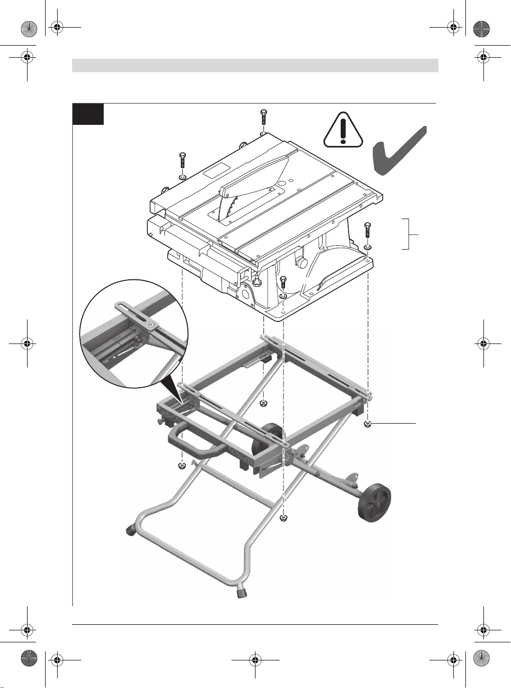
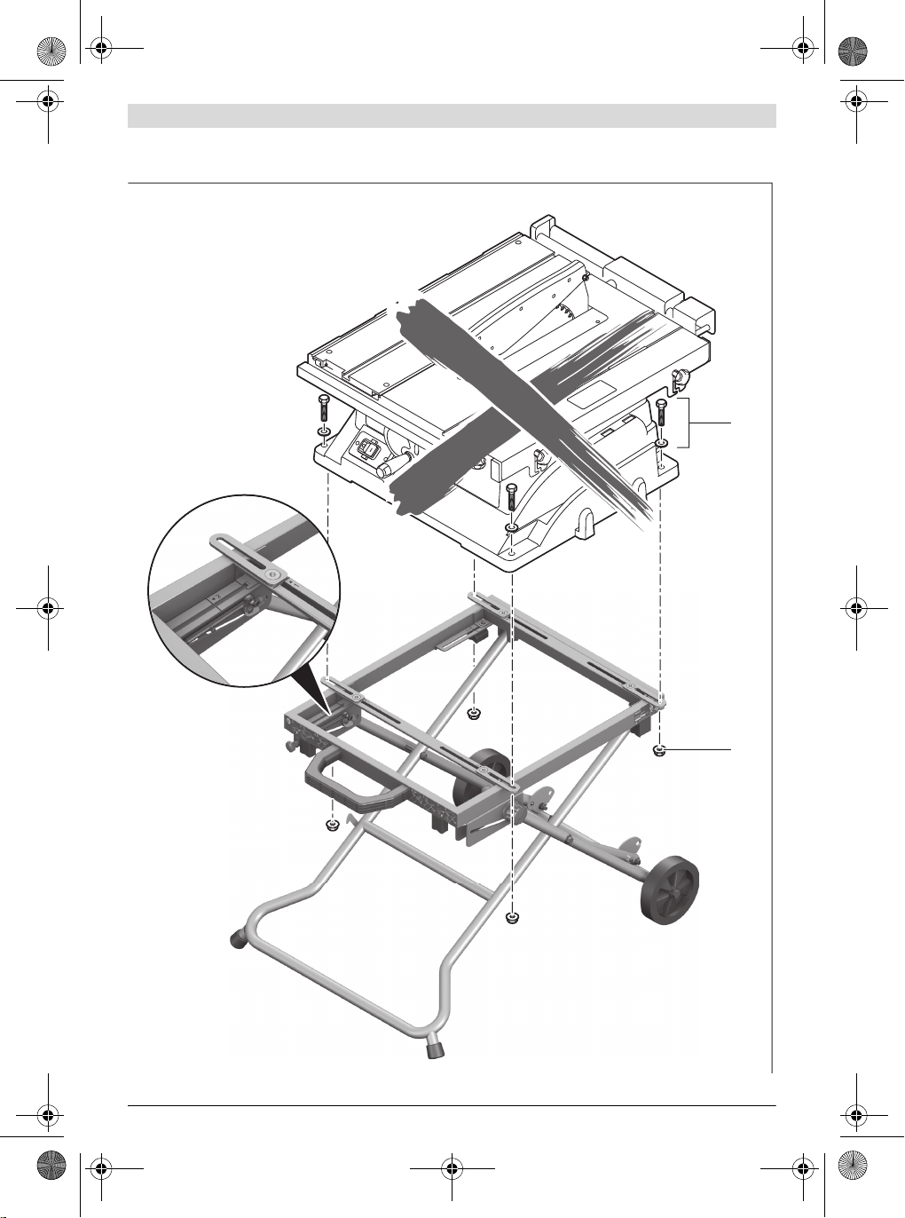
Montieren Sie das Elektrowerkzeug nur so
wie im jeweiligen Bild dargestellt.
(siehe Bilder B1–B2)
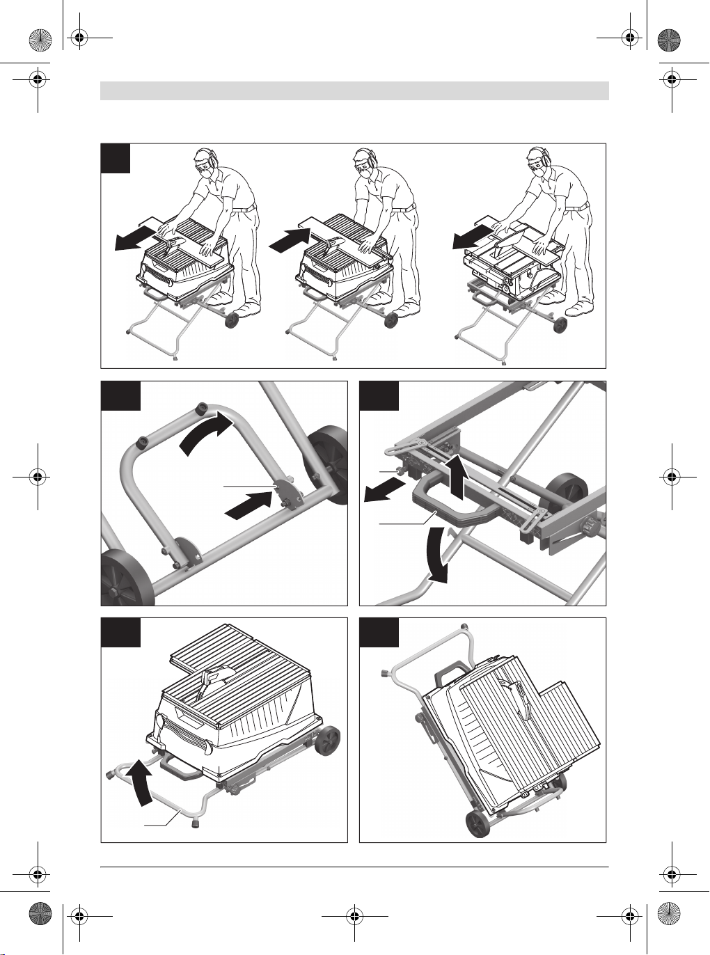
Beachten Sie die Bedienposition. Stellen
Sie sich zum Arbeiten immer auf die Seite
der Räder. (siehe Bild C)
f Überlasten Sie den Arbeitstisch
nicht und verwenden Sie diesen
nicht als Leiter oder Gerüst. Überlas-
tung oder Stehen auf dem Arbeitstisch
kann dazu führen, dass sich der
Schwerpunkt des Arbeitstischs nach
oben verlagert und dieser umkippt.
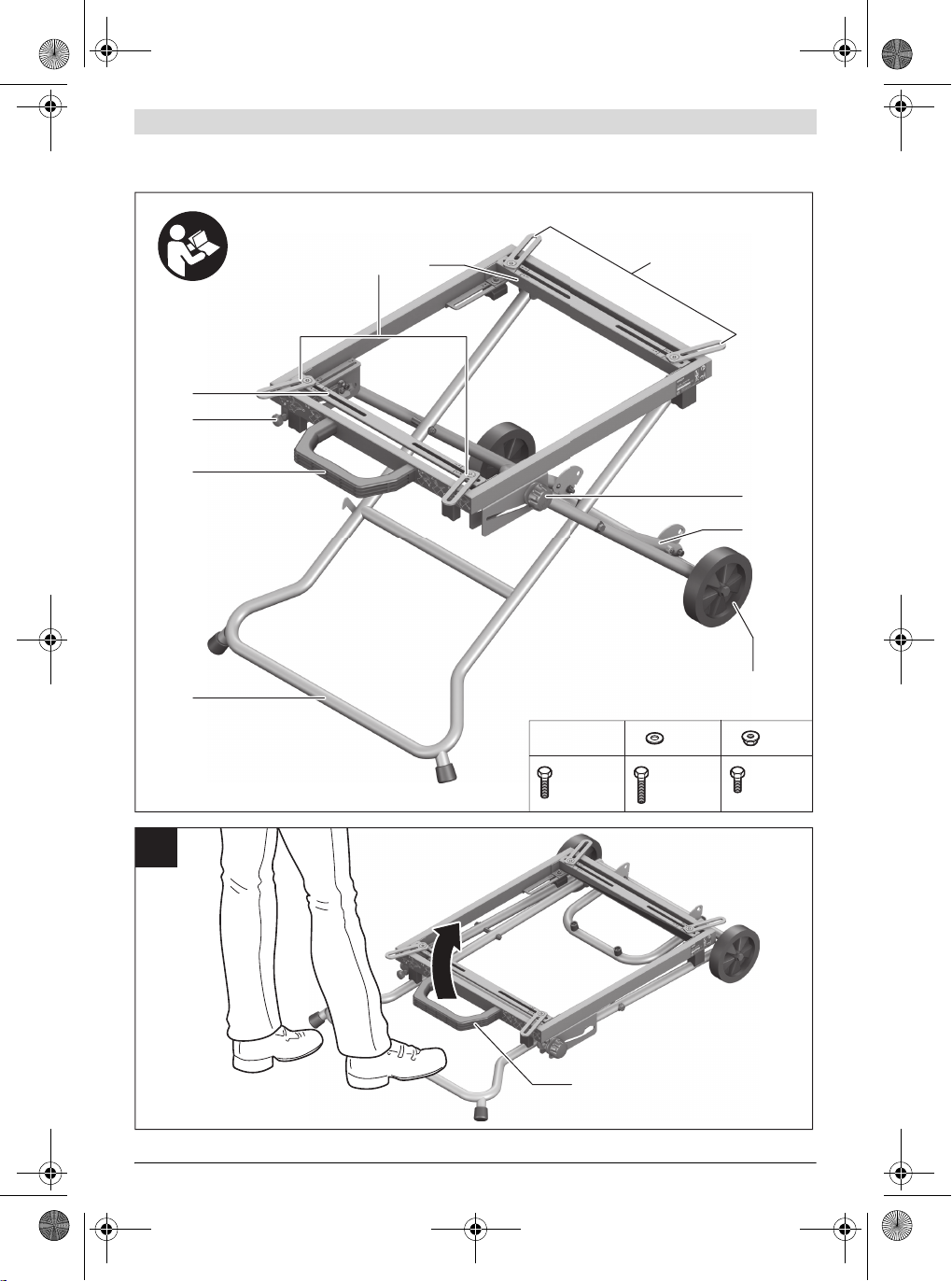
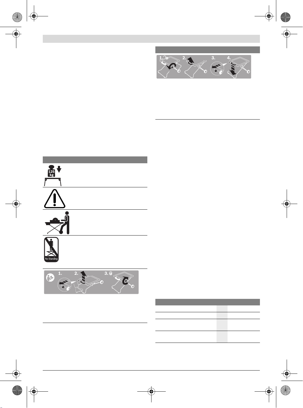
Zeigt die einzelnen Schritte zum Aufstellen des Arbeitstisches.
1. Entriegelungsknopf ziehen
2. Fuß auf den Transportgriff stellen und Handgriff nach
oben ziehen
3. Arretierknauf fest anziehen
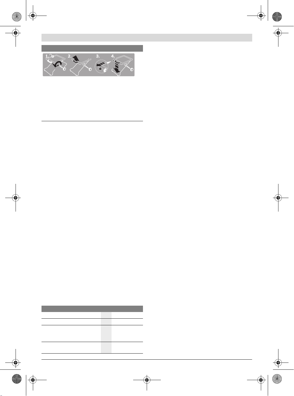
Zeigt die einzelnen Schritte zum Zusammenlegen des Arbeitstisches.
1. Arretierknauf lösen
2. Handgriff leicht nach oben ziehen
3. Entriegelungsknopf ziehen
4. Arbeitstisch am Handgriff langsam nach unten führen
Bosch Power Tools 1 619 929 K24 | (28.3.12)
Page 10

OBJ_BUCH-1563-002.book Page 10 Wednesday, March 28, 2012 1:05 PM
10 | Deutsch
Produkt- und Leistungsbeschreibung
Bestimmungsgemäßer Gebrauch
Der Arbeitstisch ist bestimmt, folgende Stationärsägen von
Bosch aufzunehmen (Stand 2012.02):
– PPS 7S 3 603 M03 3..
– PTS 10 3603L032..
Zusammen mit dem Elektrowerkzeug ist der Arbeitstisch bestimmt zum Ablängen von Brettern und Profilen.
Abgebildete Komponenten
Die Nummerierung der abgebildeten Komponenten bezieht
sich auf die Darstellung des Arbeitstisches auf den Grafikseiten.
1 Handgriff
2 Ver-/Entriegelungsknopf
3 Querstreben
4 Aufnahmeadapter
5 Arretierknauf
6 Abstellbügel
7 Transporträder
8 Transportgriff
9 Befestigungsset Elektrowerkzeug
10 Sperrbolzen des Abstellbügels
Abgebildetes oder beschriebenes Zubehör gehört nicht zum Standard-Lieferumfang. Das vollständige Zubehör finden Sie in unserem Zubehörprogramm.
Technische Daten
Arbeitstisch PTA 2000
Sachnummer
Höhe Arbeitstisch
max. Tragfähigkeit (Elektrowerk-
zeug + Werkstück)
Gewicht entsprechend
EPTA-Procedure 01/2003
3 603 M05 300
mm 595
kg 125
kg 13
Montage
Lieferumfang
Prüfen Sie vor der Montage des Arbeitstisches, ob alle unten
aufgeführten Teile mitgeliefert wurden:
– Arbeitstisch PTA 2000
– Befestigungsset 9 bestehend aus:
Sechskantschraube M8 x 45 (3 Stück),
Sechskantschraube M8 x 55 (1 Stück/PPS 7 S),
Sechskantschraube M8 x 35 (1 Stück/PTS 10),
Unterlegscheiben (4 Stück),
Sperrzahnmuttern M8 (4 Stück)
Zusätzlich zum Lieferumfang benötigte Werkzeuge:
– Schraubenschlüssel (13 mm) (2 Stück)
– Innensechskantschlüssel (5 mm)
Arbeitstisch vorbereiten
Arbeitstisch aufstellen (siehe Bild A)
Vor dem Befestigen des Elektrowerkzeugs müssen Sie den Arbeitstisch aufstellen.
– Legen Sie den Arbeitstisch mit den Beinen nach unten auf
den Boden.
– Lösen Sie bei Bedarf den Arretierknauf 5.
– Stellen Sie einen Fuß auf den Transportgriff 8, entriegeln
Sie den Ver-/Entriegelungsknopf 2 und ziehen Sie den
Handgriff 1 solange nach oben bis die Sperrbolzen einras-
ten.
– Ziehen Sie den Arretierknauf 5 fest an.
Elektrowerkzeug befestigen
(PPS 7S: siehe Bild B1)
(PTS 10: siehe Bild B2)
Montieren Sie das Elektrowerkzeug so auf dem Arbeitstisch,
dass sich die Bedienelemente des Elektrowerkzeugs oberhalb der Räder befinden.
– Bringen Sie das Elektrowerkzeug in die Transportste llung.
Hinweise zur Transportstellung finden Sie in der Be-
triebsanleitung des jeweiligen Elektrowerkzeugs.
– Drehen und schieben Sie die Aufnahmeadapter 4 wie im
Bild gezeigt in die für das jeweilige Elektrowerkzeug pas-
sende Position (PPS 7: Markierungen 2; PTS 10: Markie-
rungen 1).
– Positionieren Sie das Elektrowerkzeug so auf den Aufnah -
meadaptern, dass die Montagebohrungen am Elektro-
werkzeug mit den Langlöchern des Aufnahmeadapters zur
Deckung gebracht werden.
– Verschrauben Sie die Aufnahmeadapter und das Elektro-
werkzeug mit den Sechskantschrauben, Unterlegscheiben
und Sperrzahnmuttern aus dem Befestigungsset 9.
Betrieb
Arbeitshinweise
Stellen Sie sicher, dass vor dem Arbeiten der Arretierknauf 5
immer fest angezogen ist.
Überlasten Sie den Arbeitstisch nicht. Beachten Sie immer
die maximale Tragfähigkeit des Arbeitstischs.
Halten Sie das Werkstück immer gut fest, besonders den längeren, schwereren Abschnitt. Nach dem Durchtrennen des
Werkstücks kann sich der Schwerpunkt so ungünstig verlagern, dass die Werkstück-Abschnitte kippen.
Stützen Sie lange und schwere Werkstücke am freien Ende
ab, z. B. mit Hilfe der Rollenauflage PTA 1000 von Bosch.
Abstellbügel
Mit Hilfe des Abstellbügels 6 können Sie den Arbeitstisch mit
darauf montierem Elektrowerkzeug platzsparend aufrecht
abstellen. Idealerweise stellen Sie den Arbeitstisch mit dem
Elektrowerkzeug gegen eine Wand, um ein Kippen zu verhindern.
– Drücken Sie die Sperrbolzen 10 des Abstellbügels nach in-
nen und klappen Sie den Abstellbügel 6 ganz nach innen
bis die Sperrbolzen wieder einrasten.
1 619 929 K24 | (28.3.12) Bosch Power Tools
Page 11
OBJ_BUCH-1563-002.book Page 11 Wednesday, March 28, 2012 1:05 PM
Transport (siehe Bilder D1– D4)
Zum Transport müssen Sie den Arbeitstisch zusammenlegen.
– Drücken Sie die Sperrbolzen 10 des Abstellbügels nach in-
nen und klappen Sie den Abstellbügel 6 ganz nach außen
bis die Sperrbolzen wieder einrasten.
– Lösen Sie den Arretierknauf 5.
– Stellen Sie einen Fuß auf den Transportgriff 8 und ziehen
Sie den Handgriff 1 leicht nach oben, um die Sperrbolzen
zu entlasten.
– Ziehen Sie den Verriegelungsknopf 2 ganz nach außen und
führen Sie den Arbeitstisch am Handgriff langsam nach un-
ten.
– Ziehen Sie den Arretierknauf 5 fest an.
– Heben Sie den Arbeitstisch am Transportgriff 8 an.
Wartung und Service
Österreich
Tel.: +43 (01) 7 97 22 20 10
Fax: +43 (01) 7 97 22 20 11
E-Mail: service.elektrowerkzeuge@at.bosch.com
Schweiz
Tel.: +41 (044) 8 47 15 11
Fax: +41 (044) 8 47 15 51
Luxemburg
Tel.: +32 2 588 0589
Fax: +32 2 588 0595
E-Mail: outillage.gereedschap@be.bosch.com
Entsorgung
Arbeitstisch, Zubehör und Verpackungen sollen einer umweltgerechten Wiederverwertung zugeführt werden.
Änderungen vorbehalten.
Wartung
Sollte der Arbeitstisch trotz sorgfältiger Herstellungs- und
Prüfverfahren einmal ausfallen, ist die Reparatur von einer autorisierten Kundendienststelle für Bosch-Elektrowerkzeuge
ausführen zu lassen.
Geben Sie bei allen Rückfragen und Ersatzteilbestellungen
bitte unbedingt die 10-stellige Sachnummer laut Typenschild
des Arbeitstisches an.
English
Safety Notes
General Safety Rules
Kundendienst und Kundenberatung
Der Kundendienst beantwortet Ihre Fragen zu R eparatur und
Wartung Ihres Produkts sowie zu Ersatzteilen. Explosionszeichnungen und Informationen zu Ersatzteilen finden Sie
auch unter:
www.bosch-pt.com
Das Bosch-Kundenberater-Team hilft Ihnen gerne bei Fragen
zu Kauf, Anwendung und Einstellung von Produkten und Zubehören.
www.bosch-do-it.de, das Internetportal für Heimwerker und
Gartenfreunde.
www.dha.de, das komplette Service-Angebot der Deutschen
Heimwerker Akademie.
Deutschland
Robert Bosch GmbH
Servicezentrum Elektrowerkzeuge
Zur Luhne 2
37589 Kalefeld – Willershausen
Tel. Kundendienst: +49 (1805) 70 74 10*
Fax: +49 (1805) 70 74 11*
(*Festnetzpreis 14 ct/min, höchstens 42 ct/min aus Mobilfunknetzen)
E-Mail: Servicezentrum.Elektrowerkzeuge@de.bosch.com
Tel. Kundenberatung: +49 (1803) 33 57 99
(Festnetzpreis 9 ct/min, höchstens 42 ct/min aus Mobilfunknetzen)
Fax: +49 (711) 7 58 19 30
E-Mail: kundenberatung.ew@de.bosch.com
Safety Warnings for Saw Stands
f Pull the plug from the mains receptacle and/or remove
the battery from the power tool before making adjustments on the tool or changing tool accessories. Unin-
tentional switching on of the power tool is the cause of
many accidents.
f Assemble the saw stand in the proper manner before
mounting the power tool. Proper assembly is important
to prevent the risk of a collapse of the saw stand.
f Attach the power tool securely to the saw stand before
using it. Slipping off of the power tool on the saw stand
can lead to loss of control.
f Place the saw stand on a firm, level and horizontal sur-
face. If the saw stand can slip off or wobbles, the power
tool or the workpiece cannot be uniformly and securely
guided.
f Do not overload the saw stand and do not use it as a lad-
der or scaffolding. Overloading or standing on the saw
stand can lead to the upward shifting of the centre of gravity of the stand and its tipping over.
f When working or transporting, take care that all bolts
and connecting elements are firmly tightened. Loose
connections can lead to instability and inexact sawing.
English | 11
Read all warning notes and instructions enclosed with the saw stand and the power tool
to be mounted. Failure to follow the warnings
and instructions may result in electric shock,
fire and/or serious injury.
Bosch Power Tools 1 619 929 K24 | (28.3.12)
Page 12
OBJ_BUCH-1563-002.book Page 12 Wednesday, March 28, 2012 1:05 PM
12 | English
f Mount and dismount the power tool only when it is in
the transport position (for instructions on the trans-
port position, also see the operating instructions of the
respective power tool). Otherwise, the power tool can
have such an unfavourable centre of gravity that it cannot
be held securely.
f Ensure that long and heavy workpieces do not affect
the equilibrium of the saw stand. Long and heavy work-
pieces must be supported at the free end (e. g., with the
Bosch PTA 1000 roller stand).
f Keep your fingers clear of the hinge points while set-
ting up or folding together the saw stand. Danger of fin-
gers being crushed or contused.
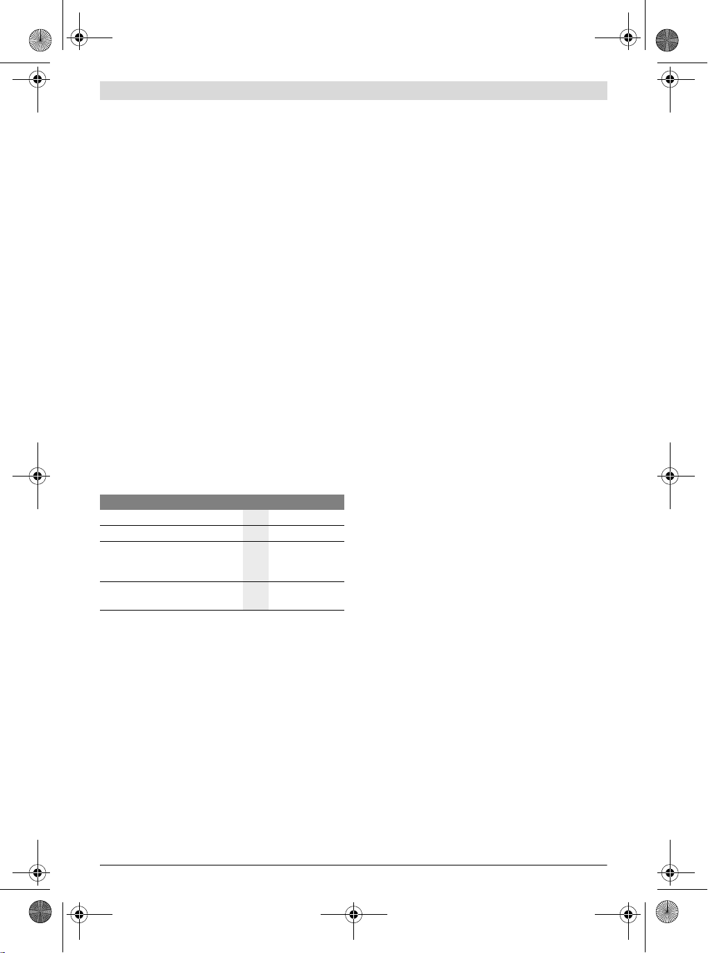
Symbol Meaning
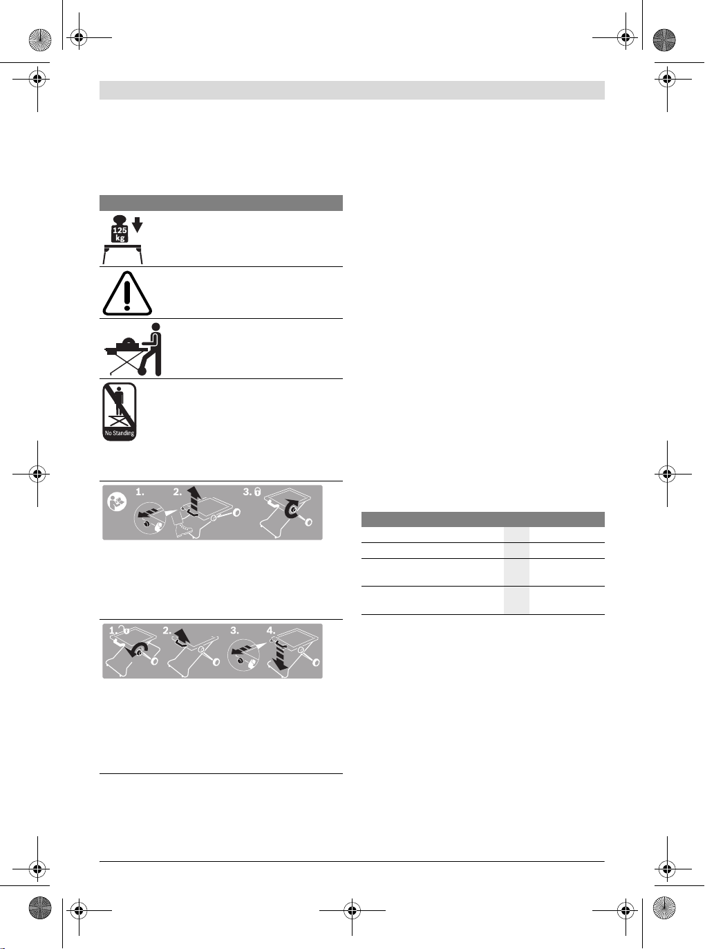
Indicates the individual steps for folding the saw stand together.
1. Loosen the locking knob
2. Pull the handle upward a little
3. Pull the release button
4. Slowly lower the saw stand by the handle
Symbols
The following symbols can be important for the operation of
your saw stand. Please memorise the symbols and their
meanings. The correct interpretation of the symbols helps
you operate the saw stand better and more secure.
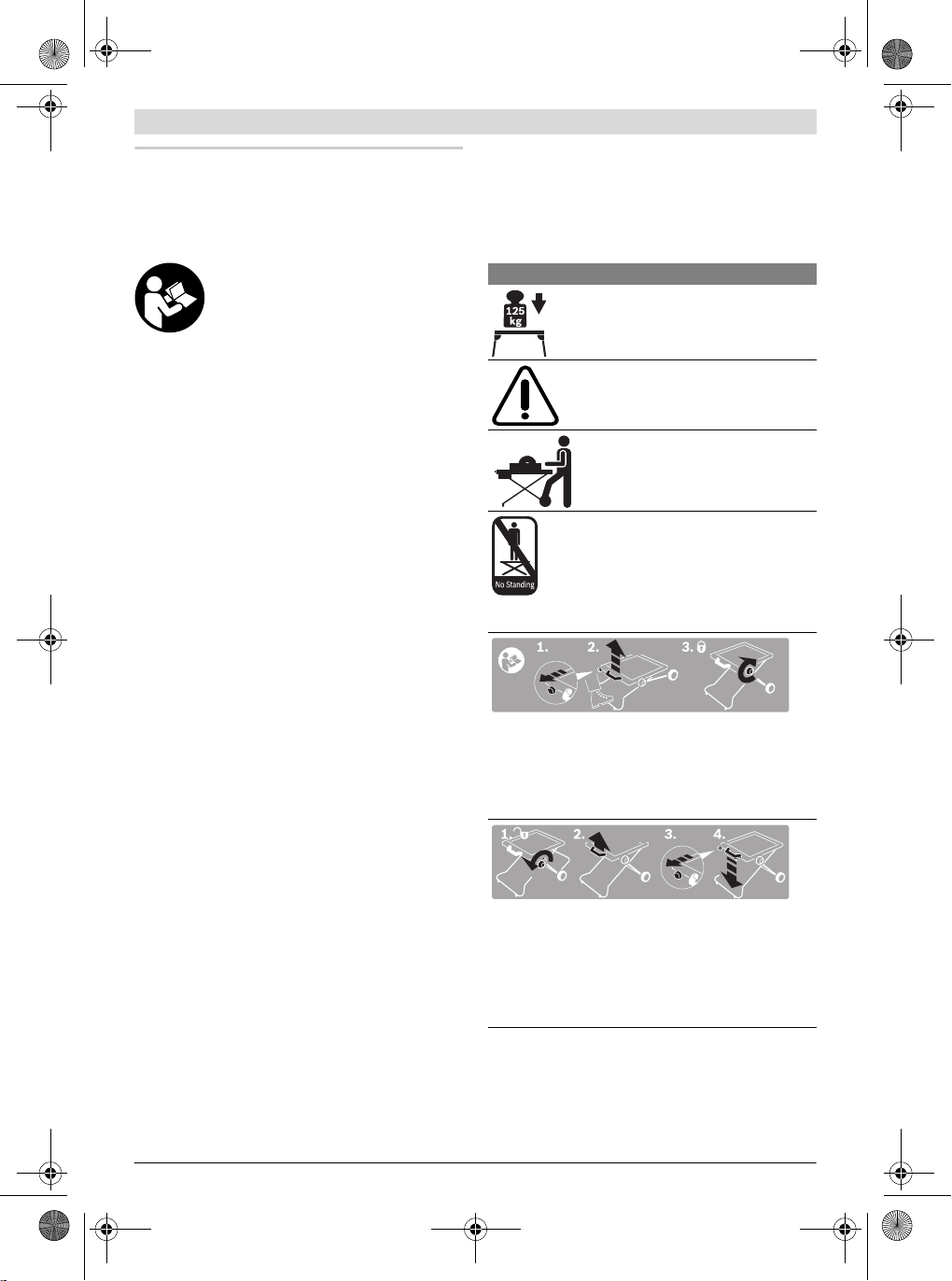
Symbol Meaning
The maximum carrying capacity (power
tool + workpiece) of the saw stand is
125 kg.
Mount the power tool only as shown in the
corresponding figure.
(seefiguresB1–B2)
Observe the operating position. When
working, always position yourself on the
side of the wheels. (see figure C)
f Do not overload the saw stand and
do not use it as a ladder or scaffolding. Overloading or standing on the
saw stand can lead to the up ward shifting of the centre of gravity of the stand
and its tipping over.
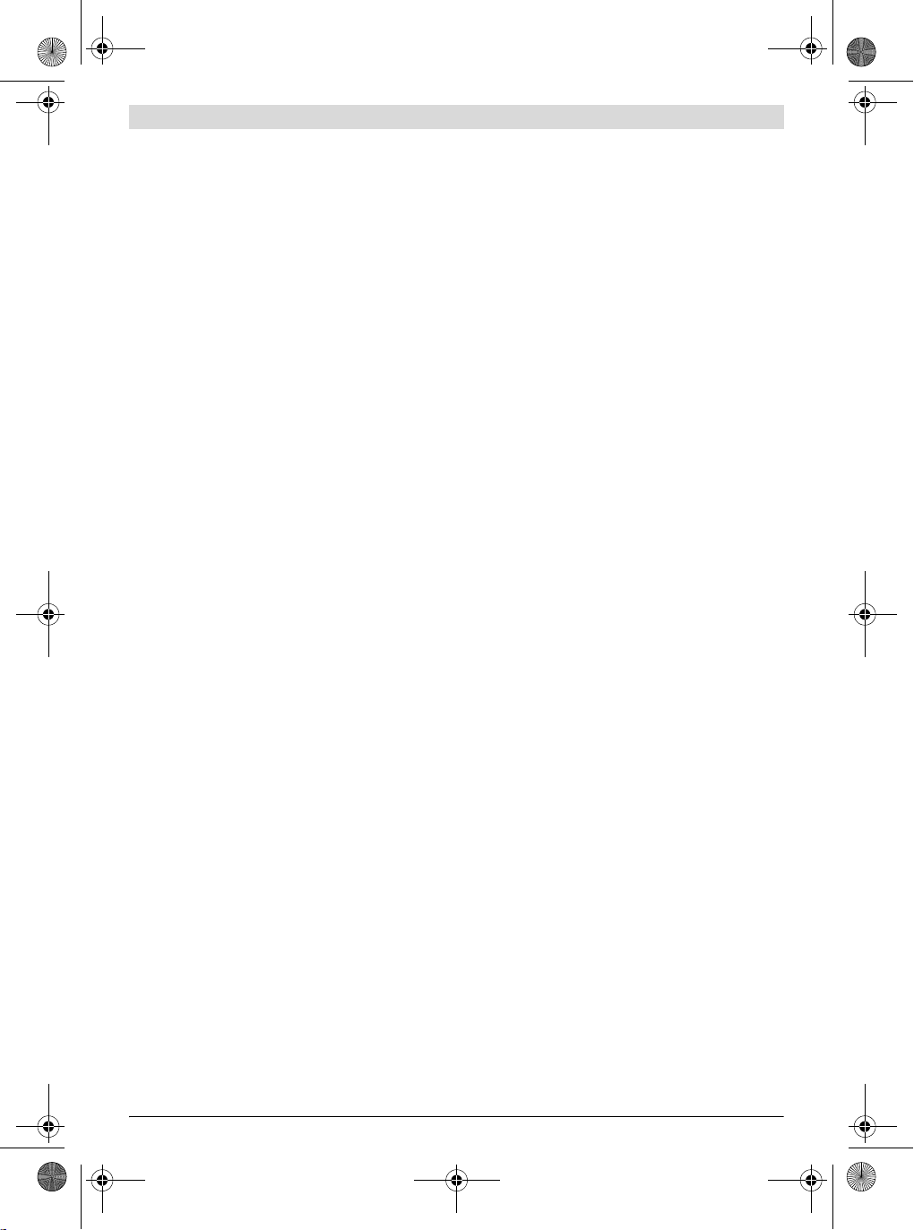
Indicates the individual steps for setting up the saw stand.
1. Pull the release button
2. Step on the transport handle and pull the handle upward
3. Firmly tighten the locking knob
Product Description and
Specifications
Intended Use
The saw stand is intended to accommodate the following stationary saws from Bosch (as of 2012.02):
– PPS 7S 3 603 M03 3..
– PTS 10 3603L032..
Together with the power tool, the saw stand is intended for
the cutting to length of boards and profiles.
Product Features
The numbering of the product features refers to the illustration of the saw stand on the graphics pages.
1 Handle
2 Lock/release button
3 Cross brace
4 Retaining adapter
5 Locking knob
6 Resting bar
7 Transport wheels
8 Transport handle
9 Fastening kit, power tool
10 Limit bolt of the resting bar
Accessories shown or described are not part of the standard delivery scope of the product. A complete overview of accessories can
be found in our accessories program.
Technical Data
Saw stand PTA 2000
Article number
Height of saw stand
Max. carrying capacity
(power tool + workpiece)
Weight according to
EPTA-Procedure 01/2003
3 603 M05 300
mm 595
kg 125
kg 13
1 619 929 K24 | (28.3.12) Bosch Power Tools
Page 13
OBJ_BUCH-1563-002.book Page 13 Wednesday, March 28, 2012 1:05 PM
Assembly
Delivery Scope
Before assembling the saw stand, check if all parts listed below are provided:
– Saw stand PTA 2000
– Fastening kit 9 consisting of:
Hexagon bolt M8 x 45 (3 pce.),
Hexagon bolt M8 x 55 (1 pce./PPS 7 S),
Hexagon bolt M8 x 35 (1 pce./PTS 10),
Washers (4 pce.),
Self-locking nuts with serrated bearing, M8 (4 pce.)
Additionally required tools (not in delivery scope):
– Open-end spanner (13 mm) (2 pce.)
– Allen key (5 mm)
Preparing the Saw Stand
Setting Up the Saw Stand (see figure A)
Set up the saw stand first before fastening the power tool.
– Lay the saw stand on the floor (legs facing down ward).
– Loosen the locking knob 5, if required.
– Position one foot on the transport handle 8, release the
lock/release button 2 and pull handle 1 upward until the
limit bolt engages.
– Tighten the locking knob 5 again.
Fastening the Power Tool
(PPS 7S: see figure B1)
(PTS 10: see figure B2)
Mount the power tool onto the saw stand in such a manner
that the power tool's operating elements are located above
the wheels.
– Position the power tool in the transport position. Notes on
the transport position are given in the operating instruc-
tions of the respective power tool.
– Turn and move the retaining adapters 4 as shown in the fig-
ure to the matching position for the corresponding power
tool (PPS 7: marks 2; PTS 10: marks 1).
– Position the power tool on the retaining adapters in such a
manner that the mounting holes on the power tool are
brought into alignment with the slots of the retaining
adapters.
– Screw the retaining adapters and the power tool together
with the hexagon bolts, washers and self-locking nuts from
the fastening kit 9.
Operation
Working Advice
Before working, always make sure that the locking knob 5 is
firmly tightened.
Do not overload the saw stand. Always observe the maximum
carrying capacity of the saw stand.
Always hold the workpiece firmly, especially the longer and
more heavy section. After cutting through the workpi ece, the
centre of gravity may become dislocated in such an unfavourable manner that the workpiece sections tip over.
Support long and heavy workpieces at the free end (e.g., with
the Bosch PTA 1000 roller stand).
Resting Bar
The resting bar 6 enables upright and place-saving storage of
the saw stand with a power tool mounted. Ideally, the saw
stand with the mounted power tool is set against a wall, in order to prevent it from tipping over.
– Press the limit bolts 10 of the resting bar in and fold the
resting bar 6 completely inward until the limit bolts engage
again.
Transport (see figures D1– D4)
The saw stand must be folded together for transport.
– Press the limit bolts 10 of the resting bar in and fold the
resting bar 6 completely outward until the limit bolts en-
gage again.
– Loosen locking knob 5.
– Position one foot on the foot lever 8 and pull the handle 1
slightly upward in order to relieve the limit bolts.
– Pull lock button 2 completely outward and slowly guide the
saw stand down by the handle.
– Tighten the locking knob 5 again.
– Grasp and raise the saw stand by the transport handle 8.
Maintenance and Service
Maintenance
If the saw stand should fail despite the care taken in manufacture and testing, repair should be carried out by an authorised
customer services agent for Bosch power tools.
In all correspondence and spare parts orders, please always
include the 10-digit article number given on the type plate of
the saw stand.
After-sales Service and Customer Assistance
Our after-sales service responds to your questions concerning maintenance and repair of your product as well as spare
parts. Exploded views and information on spare parts can also be found under:
www.bosch-pt.com
Our customer service representatives can answer your questions concerning possible applications and adjustment of
products and accessories.
Great Britain
Robert Bosch Ltd. (B.S.C.)
P.O. Box 98
Broadwater Park
North Orbital Road
Denham
Uxbridge
UB 9 5HJ
Tel. Service: +44 (0844) 736 0109
Fax: +44 (0844) 736 0146
E-Mail: boschservicecentre@bosch.com
English | 13
Bosch Power Tools 1 619 929 K24 | (28.3.12)
Page 14

OBJ_BUCH-1563-002.book Page 14 Wednesday, March 28, 2012 1:05 PM
14 | Français
Ireland
Origo Ltd.
Unit 23 Magna Drive
Magna Business Park
City West
Dublin 24
Tel. Service: +353 (01) 4 66 67 00
Fax: +353 (01) 4 66 68 88
Australia, New Zealand and Pacific Islands
Robert Bosch Australia Pty. Ltd.
Power Tools
Locked Bag 66
Clayton South VIC 3169
Customer Contact Center
Inside Australia:
Phone: +61 (01300) 307 044
Fax: +61 (01300) 307 045
Inside New Zealand:
Phone: +64 (0800) 543 353
Fax: +64 (0800) 428 570
Outside AU and NZ:
Phone: +61 (03) 9541 5555
www.bosch.com.au
Republic of South Africa
Customer service
Hotline: +27 (011) 6 51 96 00
Gauteng – BSC Service Centre
35 Roper Street, New Centre
Johannesburg
Tel.: +27 (011) 4 93 93 75
Fax: +27 (011) 4 93 01 26
E-Mail: bsctools@icon.co.za
KZN – BSC Service Centre
Unit E, Almar Centre
143 Crompton Street
Pinetown
Tel.: +27 (031) 7 01 21 20
Fax: +27 (031) 7 01 24 46
E-Mail: bsc.dur@za.bosch.com
Western Cape – BSC Service Centre
Democracy Way, Prosperity Park
Milnerton
Tel.: +27 (021) 5 51 25 77
Fax: +27 (021) 5 51 32 23
E-Mail: bsc@zsd.co.za
Bosch Headquarters
Midrand, Gauteng
Tel.: +27 (011) 6 51 96 00
Fax: +27 (011) 6 51 98 80
E-Mail: rbsa-hq.pts@za.bosch.com
Disposal
The saw stand, accessories and packaging should be sorted
for environmental-friendly recycling.
Subject to change without notice.
Français
Avertissements de sécurité
Indications générales de sécurité
Instructions de sécurité pour tables de travail
f Débrancher la fiche de la source d’alimentation en cou-
rant et/ou le bloc de batteries de l’outil avant tout ré-
glage, changement d’accessoires ou avant de ranger
l’outil. Une mise en route involontaire d’outils électropor-
tatifs est une cause courante d’accident.
f Montez correctement la table de travail avant de mon-
ter l’outil électroportatif. Un montage exact est impor-
tant pour éviter le risque que la table ne s’écroule.
f Fixez l’outil électroportatif fermement sur la table de
découpe avant de l’utiliser. Un outil électroportatif qui se
déplace sur la table de travail peut entraîner une perte de
contrôle.
f Montez la table de travail sur une surface solide, plane
et horizontale. Si la table de travail peut se déplacer ou
basculer, il n’est pas possible de guider l’outil électropo rta-
tif ou la pièce de façon uniforme et en toute sécurité.
f Ne surchargez pas la table de travail et ne l’utilisez pas
en tant qu’échelle ou échafaudage. Le fait de surcharger
la table de travail ou de se placer dessus peut avoir pour
conséquence que le centre de gravité de la table de travail
se déplace vers le haut et qu’elle se renverse.
f Veillez à ce que tous les vis et éléments d’assemblage
soient bien serrés lors du transport et lors du travail.
Des raccords desserrés peuvent entraîner des instabilités
et des opérations imprécises de sciage.
f Ne montez et démontez l’outil électroportatif que lors-
qu’il se trouve en position de transport (pour les indica-
tions concernant la position de transport, voir égale-
ment les instructions d’utilisation de l’outil
électroportatif respectif). Sinon, le centre de gravité de
l’outil électroportatif peut être défavorable de sorte que
vous ne puissiez pas le tenir en toute sécurité.
f Assurez-vous que les pièces longues et lourdes ne dé-
séquilibrent pas la table de travail. Les extrémités libres
des pièces longues et lourdes doivent être soutenues
(par ex. à l’aide du support à roulements Bosch
PTA 1000).
f Tenez toujours vos doigts à l’écart des points d’articu-
lation lorsque vous repliez ou dépliez la table de travail.
Vous pourriez vous coincer les doigts.
Lisez tous les avertissements et instructions
joints à la table de travail ou à l’outil électroportatif à assembler. Ne pas suivre les avertis-
sements et instructions peut provoquer un
choc électrique, un incendie et/ou une blessure sérieuse.
1 619 929 K24 | (28.3.12) Bosch Power Tools
Page 15
OBJ_BUCH-1563-002.book Page 15 Wednesday, March 28, 2012 1:05 PM
Français | 15
Symboles
Les symboles suivants peuvent être importants pour l’utilisation de votre table de travail. Veuillez mémoriser ces symboles et leurs significations. L’interprétation correcte des symboles vous permettra de mieux utiliser votre table de travail et
en toute sécurité.
Symbole Signification
La capacité de charge maximale (outil
électroportatif + pièce) de la table de travail est de 125 kg.
Montez toujours l’outil électroportatif
conformément à l’illustration correspondante. (voir figures B1 –B2)
Tenez compte de la position de travail. Positionnez-vous toujours du côté des
roues. (voir figure C)
f Ne surchargez pas la table de travail
et ne l’utilisez pas en tant qu’échelle
ou échafaudage. Le fait de surcharger
la table de travail ou de se placer dessus peut avoir pour conséquence que
le centre de gravité de la table de travail se déplace vers le haut et qu’elle se
renverse.
Indique les différentes étapes pour déplier la table de trava il.
1. Tirer le bouton de déverrouillage
2. Poser le pied sur la poignée de transport et tirer la poignée
vers le haut
3. Resserrer fermement le bouton de blocage
Description et performances du
produit
Utilisation conforme
La table de travail est conçue pour intégrer les scies stationnaires suivantes de Bosch (version 2012.02) :
– PPS 7S 3 603 M03 3..
– PTS 10 3603L032..
Avec l’outil électroportatif , la table de travail est conçue pour
le découpage de planches et de profilés.
Eléments de l’appareil
La numérotation des éléments se réfère à la représentation de
la table de travail sur les pages graphiques.
1 Poignée
2 Bouton de verrouillage/déverrouillage
3 Traverses
4 Eléments de fixation ajustables
5 Bouton de blocage
6 Etrier
7 Roues de transport
8 Poignée de transport
9 Set de montage de l’outil électroportatif
10 Boulon de blocage de l’étrier
Les accessoires décrits ou illustrés ne sont pas to us compris dans
la fourniture. Vous trouverez les accessoires complets dans notre
programme d’accessoires.
Caractéristiques techniques
Table de travail PTA 2000
N° d’article
Hauteur de la table de travail
Capacité de charge max.
(outil électroportatif + pièce) kg 125
Poids suivant EPTA-Procedure
01/2003
3 603 M05 300
mm 595
kg 13
Montage
Accessoires fournis
Avant le montage de la table de travail, vérifiez si toutes les
Indique les différentes étapes pour replier la table de travail.
1. Desserrer le bouton de blocage
2. Tirer légèrement la poignée vers le haut
3. Tirer le bouton de déverrouillage
4. Pousser lentement la table de travail vers le bas en la te-
nant par la poignée
Bosch Power Tools 1 619 929 K24 | (28.3.12)
pièces indiquées ci-dessous ont été fournies :
– Table de travail PTA 2000
– Set de montage 9, comprenant :
boulon à tête hexagonale M8 x 45 (3),
boulon à tête hexagonale M8 x 55 (1/PPS 7 S),
boulon à tête hexagonale M8 x 35 (1/PTS 10),
rondelles (4),
écrous auto-bloquant M8 (4)
D’autres outils nécessaires, pas fournis avec l’appareil :
– Clé (13 mm) (2 pièces)
– Clé mâle pour vis à six pans creux (5 mm)
Page 16

OBJ_BUCH-1563-002.book Page 16 Wednesday, March 28, 2012 1:05 PM
16 | Français
Préparation de la table de travail
Installer la table de travail (voir figure A)
Montez la table de travail avant d’y fixer l’outil électroportatif.
– Posez la table de travail sur le sol, les pieds vers le bas.
– Si nécessaire, desserrez le bouton de blocage 5.
– Posez un pied sur la poignée de transpo rt 8, déverrouillez
le bouton de verrouillage/déverrouillage 2 et tirez la poignée 1 vers le haut jusqu’à ce que les boulons de blocage
s’encliquettent.
– Serrez fermement le bouton de blocage 5.
Montage de l’outil électroportatif
(PPS 7S : voir figure B1)
(PTS 10 : voir figure B2)
Montez l’outil électroportatif sur la table de travail de manière
à ce que les éléments de commande de l’outil électroportatif
soient au-dessus des roues.
– Mettez l’outil électr oportatif en position de transport.Vous
trouverez des indications pour la position de transport
dans les instructions d’utilisation de l’outil électroportatif
respectif.
– Faites pivoter et ajuster les éléments de fixation 4 confor-
mément aux indications sur l’illustration pour les mettre
dans la position appropriée à l’outil électroportatif correspondant (PPS 7 : marquages 2 ; PTS 10 : marquages 1).
– Positionnez l’outil électroportatif sur les éléments de fixa-
tion ajustables de sorte à faire coïncider les alésages de
fixation de l’outil électroportatif avec les trous oblongs de
l’élément de fixation.
– Vissez les éléments de fixation et l’outil électroportatif
avec les vis à tête hexagonale, les rondelles et les écrous
auto-bloquant du set de fixation 9.
Fonctionnement
Instructions d’utilisation
Assurez-vous avant l’utilisation de la machine que le bouton
de blocage 5 est bien serré.
Ne surchargez pas la table de travail. Respectez toujours la capacité de charge maximale de la table de travail.
Tenez toujours fermement la pièce, surtout la partie plus longue, en l’occurrence la plus lourde. Une fois la pièce découpée, le centre de gravité peut se déplacer défavorablement et
faire basculer les différentes parties de la pièce à travailler.
Soutenez les extrémités libres des pièces longues et lourdes,
par ex. à l’aide du support à roulements PTS 1000 de Bosch.
Etrier
L’étrier 6 vous permet de ranger la table de travail verticalement avec l’outil électroportatif monté de manière peu encombrante. Placez de préférence la table de travail avec l’outil
électroportatif contre un mur pour éviter tout basculement.
– Poussez les boulons de blocage 10 de l’étrier vers l’inté-
rieur et repliez l’étrier 6 complètement vers l’intérieur jusqu’à ce que les boulons de blocage s’encliquettent à nouveau.
Transport (voir figure D1 —D4)
Pour le transport vous devez plier la table de travail.
– Poussez les boulons de blocage 10 de l’étrier vers l’inté-
rieur et repliez l’étrier 6 complètement vers l’intérieur jus-
qu’à ce que les boulons de blocage s’encliquettent à nou-
veau.
– Desserrez le bouton de blocage 5.
– Posez un pied sur la poignée de transport 8 et tirez légère-
ment la poignée 1 vers le haut pour délester les boulons de
blocage.
– Ti rez le bo uton de verrou illage 2 complètement vers l’exté-
rieur et poussez la table de travail lentement vers le bas en
la tenant par la poignée.
– Serrez fermement le bouton de blocage 5.
– Soulevez la table de travail par la poignée de transport 8.
Entretien et Service Après-Vente
Entretien
Si, malgré tous les soins apportés à la fabrication et au con trôle de la table de travail, celle-ci présentait un défaut, la réparation ne doit être confiée qu’à une station de service aprèsvente agréée pour outillage Bosch.
Pour toute demande de renseignement ou commande de pièces de rechange, nous préciser impérativement le numéro
d’article à dix chiffres de la table de travail indiqué sur la plaque signalétique.
Service Après-Vente et Assistance Des Clients
Notre Service Après-Vente répond à vos questions concernant la réparation et l’entretien de votre produit et les pièces
de rechange. Vous trouverez des vues éclatées ainsi que des
informations concernant les pièces de rechange également
sous :
www.bosch-pt.com
Les conseillers techniques Bosch sont à votre disposition
pour répondre à vos questions concernant l’achat, l’utilisation
et le réglage de vos produits et de leurs accessoires.
France
Vous êtes un utilisateur, contactez :
Le Service Clientèle Bosch Outillage Electroportatif
Tel. : 0 811 36 01 22
(coût d’une communication locale)
Fax : +33 (0) 1 49 45 47 67
E-Mail : contact.outillage-electroportatif@fr.bosch.com
Vous êtes un revendeur, contactez :
Robert Bosch (France) S. A.S.
Service Après-Vente Electroportatif
126, rue de Stalingrad
93705 DRANCY Cédex
Tel. : +33 (0) 1 43 11 90 06
Fax : +33 (0) 1 43 11 90 33
E-Mail : sav.outillage-electroportatif@fr.bosch.com
1 619 929 K24 | (28.3.12) Bosch Power Tools
Page 17
OBJ_BUCH-1563-002.book Page 17 Wednesday, March 28, 2012 1:05 PM
Belgique, Luxembourg
Tel. : +32 2 588 0589
Fax : +32 2 588 0595
E-Mail : outillage.gereedschap@be.bosch.com
Suisse
Tel. : +41 (044) 8 47 15 12
Fax : +41 (044) 8 47 15 52
Elimination des déchets
Les tables de travail, ainsi que leurs accessoires et emballages, doivent pouvoir suivre chacun une voie de recyclage appropriée.
Sous réserve de modifications.
sultar también al respecto las instrucciones de manejo
de la respectiva herramienta eléctrica). En caso contra-
rio podría quedar en una posición tan desfavorable el cen-
tro de gravedad de la herramienta eléctrica, que no le sea
posible sujetarla de forma segura.
f Asegúrese que las piezas largas y pesadas no hagan
volcar la mesa de trabajo. En las piezas de trabajo largas
y pesadas deberá soportarse su extremo libre (en voladi-
zo) (p. ej., con ayuda del soporte de rodillos PTA 1000 de
Bosch).
f Mantenga alejados sus dedos de las articulaciones de
la mesa de trabajo al desplegar o plegar la misma. Sus
dedos podrían ser magulladfos.
Símbolos
Los símbolos mostrados a continuación pueden ser de impor-
Español
Instrucciones de seguridad
Instrucciones generales de seguridad
Lea íntegramente las advertencias de peligro e instrucciones que se adjuntan con la
mesa de trabajo y con la herramienta eléctrica que desee acoplar a la misma. En caso de
no atenerse a las indicaciones de seguridad e
instrucciones, ello puede ocasionar una descarga eléctrica, un incendio y/o lesión grave.
Instrucciones de seguridad para mesas de trabajo
f Saque el enchufe de la red y/o desmonte el acumulador
de la herramienta eléctrica antes de realizar un ajuste
en el aparato o al cambiar de accesorio. La puesta en
marcha accidental de la herramienta eléctrica puede provocar accidentes.
f Ensamble correctamente la mesa de trabajo antes de
acoplar a ella la herramienta eléctrica. Un ensamble co-
rrecto es primordial para conseguir una buena estabilidad
y evitar accidentes.
f Antes de utilizarla, sujete firmemente la herramienta
eléctrica a la mesa de trabajo. Podría perder el control
sobre la herramienta eléctrica si ésta no va correctamente
sujeta a la mesa de trabajo.
f Coloque la mesa de trabajo sobre una superficie firme,
plana y horizontal. Si la mesa de trabajo llega a desplazar-
se, o cojea, no es posible guiar uniformemente ni de forma
segura la herramienta eléctrica o la pieza.
f No coloque pesos excesivos sobre la mesa de trabajo ni
la emplee como escalera o andamio. Al sobrecargar o su-
birse a la mesa de trabajo puede ocurrir que ésta vuelque.
f Al transportar la mesa o al trabajar con ella, preste
atención a que estén firmemente apretados todos los
tornillos y elementos de unión. Una sujeción deficiente
puede provocar una inestabilidad y un serrado inexacto.
f Solamente acople y desacople la herramienta eléctrica
encontrándose ésta en la posición de transporte (con-
tancia en el uso de la mesa de trabajo. Es importante que retenga en su memoria estos símbolos y su significado. La interpretación correcta de estos símbolos le ayudará a manejar
mejor, y de forma más segura, la mesa de trabajo.
Simbología Significado
Muestra los diversos pasos precisados para colocar la mesa
de trabajo.
1. Tirar del seguro
2. Apoyar el pie sobre la empuñadura de transporte y tirar
del asa hacia arriba
3. Apretar firmemente el pomo de bloqueo
Español | 17
La capacidad de carga máxima (herramienta eléctrica + pieza de trabajo) de la
mesa de trabajo es de 125 kg.
Únicamente monte la herramienta eléctrica según se muestra en la respectiva figura. (ver figuras B1 –B2)
Preste atención a la posición de manejo.
Al trabajar sitúese siempre en el lado de
las ruedas. (ver figura C)
f No coloque pesos excesivos sobre la
mesa de trabajo ni la emplee como
escalera o andamio. Al sobrecargar o
subirse a la mesa de trabajo puede ocurrir que ésta vuelque.
Bosch Power Tools 1 619 929 K24 | (28.3.12)
Page 18
OBJ_BUCH-1563-002.book Page 18 Wednesday, March 28, 2012 1:05 PM
18 | Español
Simbología Significado
Muestra los diversos pasos precisados para plegar la mesa
de trabajo.
1. Aflojar el pomo de bloqueo
2. Tirar levemente hacia arriba del asa
3. Tirar del seguro
4. Sujetar la mesa de trabajo del asa y descenderla lenta-
mente
Descripción y prestaciones del
producto
Utilización reglamentaria
La mesa de trabajo ha sido diseñada para montar sobre ella
las siguientes sierras estacionarias Bosch
(situación 2012.02):
– PPS 7S 3 603 M03 3..
– PTS 10 3603L032..
La mesa de trabajo, en combinación con la herramienta eléctrica, ha sido concebida para cortar a longitud tablas y perfiles.
Componentes principales
La numeración de los componentes está referida a la imagen
de la mesa de trabajo en las páginas ilustradas.
1 Empuñadura
2 Seguro
3 Barras transversales
4 Adaptador
5 Pomo de bloqueo
6 Estribo de apoyo
7 Ruedas de transporte
8 Empuñadura de transporte
9 Juego de piezas de sujeción de la herramienta eléctrica
10 Bulón de retención del estribo de apoyo
Los accesorios descritos e ilustrados no corresponden al mat erial
que se adjunta de serie. La gama completa de ac cesorios opcionales se detalla en nuestro programa de accesorios.
Datos técnicos
Mesa de trabajo PTA 2000
Nº de artículo
Altura de la mesa de trabajo
Capacidad de carga máx.
(herramienta eléctrica + pieza de
trabajo)
Peso según EPTA-Procedure
01/2003
3 603 M05 300
mm 595
kg 125
kg 13
Montaje
Material que se adjunta
Antes de montar la mesa de trabajo compruebe si se han suministrado todas las partes que a continuación se detallan:
– Mesa de trabajo PTA 2000
– Juego de piezas de sujeción 9 compuesto por:
Tornillo de cabeza hexagonal M8 x 45 (3 unidades),
Tornillo de cabeza hexagonal M8 x 55 (1 unidad/PPS 7 S),
Tornillo de cabeza hexagonal M8 x 35 (1 unidad/PTS 10),
Arandelas (4 unidades)
Tuercas dentadas autoblocantes M8 (4 unidades)
Herramientas necesarias que no se adjuntan con el
aparato:
– Llave fija (13 mm) (2 unidades)
– Llave macho hexagonal (5 mm)
Preparación de la mesa de trabajo
Colocación de la mesa de trabajo (ver figura A)
La mesa de trabajo deberá desplegarse prime ro, antes de fijar
a la misma la herramienta eléctrica.
– Deposite la mesa de trabajo sobre el suelo con las patas ha-
cia abajo.
– Si procede, afloje el pomo de bloqueo 5.
– Apoye un pie contra la empuñadura de transporte 8, des-
bloquee el seguro 2, y tire hacia arriba del asa 1 hasta lo-
grar que enclaven los bulones de retención.
– Apriete firmemente el pomo de bloqueo 5.
Fijación de la herramienta eléctrica
(PPS 7S: ver figura B1)
(PTS 10: ver figura B2)
Monte la herramienta eléctrica sobre la mesa de trabajo de
manera que los elementos de manejo de la herramienta eléctrica queden por encima de las ruedas.
– Coloque la herramienta eléctrica en la posición de trans-
porte. Indicaciones referentes a la posición de transporte
las encontrará en las instrucciones de servicio de la res-
pectiva herramienta eléctrica.
– Gire y desplace los adaptadores 4 según figura a la posi-
ción que corresponda a la herramienta eléctrica utilizada
(PPS 7: marcas 2; PTS 10: marcas 1).
– Deposite la herramienta eléctrica sobre los adaptadores
haciendo coincidir los agujeros de sujeción de la misma
con los agujeros alargados de los adaptadores.
– Fije la herramienta eléctrica a los adaptadores con los tor-
nillos de cabeza hexagonal, arandelas, y tuercas dentadas
autoblocantes comprendidas en el juego de piezas de suje-
ción 9.
Operación
Instrucciones para la operación
Antes de comenzar a trabajar asegúrese siempre que esté f irmemente apretado el pomo de bloqueo 5.
No sobrecargue la mesa de trabajo. Siempre tenga e n cuenta
la capacidad de carga máxima de la mesa de trabajo.
1 619 929 K24 | (28.3.12) Bosch Power Tools
Page 19

OBJ_BUCH-1563-002.book Page 19 Wednesday, March 28, 2012 1:05 PM
En todo momento sujete con firmeza la pieza de trabajo, especialmente el trozo más largo y pesado. Al cortar la pieza de trabajo los trozos divididos que sobresalen de la mesa pueden
caer hacia los lados por su propio peso.
Soporte el extremo libre (en voladizo) en las piezas de trabajo
largas y pesadas, p. ej., con ayuda del soporte de rodillo s
PTA 1000 de Bosch.
Estribo de apoyo
El estribo de apoyo 6 le permite depositar en posición vertica l
la mesa de trabajo con la herramienta eléctrica acoplada sin
requerir mucho espacio. Se recomienda colocar la mesa de
trabajo con la herramienta eléctrica apoyándola contra una
pared para evitar que vuelque.
– Presione hacia dentro los bulones de retención 10 del es-
tribo de apoyo y abata completamente hacia dentro el estribo de apoyo 6 hasta enclavar de nuevo los bulones de retención.
Transporte (ver figuras D1 — D4)
Para su transporte es necesario plegar la mesa de trabajo.
– Presione hacia dentro los bulones de retención 10 del es-
tribo de apoyo y abata completamente hacia fuera el estribo de apoyo 6 hasta enclavar de nuevo los bulones de re-
tención.
– Afloje el pomo de bloqueo 5.
– Apoye un pie contra la empuñadura de transporte 8 y tire
levemente hacia arriba del asa 1 para descargar los bulo-
nes de retención.
– Saque completamente hacia fuera el seguro 2 y descienda
lentamente la mesa de trabajo sujetándola del asa.
– Apriete firmemente el pomo de bloqueo 5.
– Tire de la mesa de trabajo asiéndola por la empuñadura de
transporte 8.
Mantenimiento y servicio
Mantenimiento
Si a pesar de los esmerados procesos de fabricación y control, la mesa de trabajo llegase a averiarse, la reparación deberá encargarse a un taller de servicio auto rizado para herramientas eléctricas Bosch.
Para cualquier consulta o pedido de piezas de repuesto es imprescindible indicar el nº de artículo de 10 dígitos que figura
en la placa de características de la mesa de trabajo.
Servicio técnico y atención al cliente
El servicio técnico le asesorará en las consultas que pueda
Ud. tener sobre la reparación y mantenimiento de su producto, así como sobre piezas de recambio. Los dibujos de despiece e informaciones sobre las piezas de recambio los podrá obtener también en internet bajo:
www.bosch-pt.com
Nuestro equipo de asesores técnicos le orientará gustosamente en cuanto a la adquisición, aplicación y ajuste de los
productos y accesorios.
España
Robert Bosch Espana S.L.U.
Departamento de ventas Herramientas Eléctricas
C/Hermanos García Noblejas, 19
28037 Madrid
Tel. Asesoramiento al cliente: +34 902 53 15 53
Fax: +34 902 53 15 54
Venezuela
Robert Bosch S.A.
Final Calle Vargas. Edf. Centro Berimer P.B.
Boleita Norte
Caracas 107
Tel.: +58 (02) 207 45 11
México
Robert Bosch S. de R.L. de C.V.
Circuito G. Gonzáles Camarena 333
Centro de Ciudad Santa Fe - 01210 - Mexico DF
Tel. Interior: +52 (01) 800 627 1286
Tel. D.F.: +52 (01) 52 84 30 62
E-Mail: arturo.fernandez@mx.bosch.com
Argentina
Robert Bosch Argentina S.A.
Av. Córdoba 5160
C1414BAW Ciudad Autónoma de Buenos Aires
Atención al Cliente
Tel.: +54 (0810) 555 2020
E-Mail: herramientas.bosch@ar.bosch.com
Perú
Robert Bosch S.A.C.
Av. Republica de Panama 4045
Buzón Postal Lima 34 (Surquillo) - Lima
Tel.: +51 1706 1100
Chile
Robert Bosch S.A.
Calle San Eugênio, 40
Ñuñoa - Santiago
Buzón Postal 7750000
Tel.: +56 (02) 520 3100
E-Mail: emasa@emasa.cl
Eliminación
La mesa de trabajo, los accesorios y embalajes deberán someterse a un proceso de recuperación que respete el medio
ambiente.
Reservado el derecho de modificación.
Español | 19
Bosch Power Tools 1 619 929 K24 | (28.3.12)
Page 20
OBJ_BUCH-1563-002.book Page 20 Wednesday, March 28, 2012 1:05 PM
20 | Português
Português
Indicações de segurança
Indicações gerais de segurança
Leia todas as indicações de advertência e
instruções enviadas junto com a mesa de
trabalho ou com a ferramenta eléctrica a ser
montada. O desrespeito das instruções de se-
gurança pode causar choque eléctrico, incêndios e/ou graves lesões.
Indicações de segurança para mesas de trabalho
f Puxar a ficha da tomada e/ou retirar o acumulador da
ferramenta eléctrica, antes de executar ajustes no apa-
relho ou de substituir peças e acessórios. O arranque in-
voluntário de ferramentas eléctricas é a causa de alguns
acidentes.
f Montar correctamente a mesa de trabalho, antes de
montar a ferramenta eléctrica. É importante que a mon-
tagem seja perfeita, para evitar o risco de desmoronamen-
to.
f Fixar firmemente a ferramenta eléctrica na mesa de
trabalho antes de utilizá-la. Se a ferramenta eléctrica se
deslocar sobre a mesa de trabalho, poderá perder o con-
trolo sobre a ferramenta.
f Apoiar a mesa de trabalho sobre uma superfície firme,
plana e horizontal. Se a mesa de trabalho puder se deslo-
car ou se balançar, não será possível conduzir com segu-
rança a ferramenta eléctrica nem a peça a ser trabalhada.
f Não sobrecarregar a mesa de trabalho e não utilizá-la
como escada de mão nem como andaime. Se sobrecar-
regar ou se subir na mesa de trabalho, poderá ser que o
centro de gravidade se desloque para cima e que a mesa
tombe.
f Durante o transporte e durante o trabalho, deverá as-
segurar-se de que todos os parafusos e elementos de
união estejam bem apertados. Uniões soltas podem le-
var a instabilidades e a processos de corte imprecisos.
f Só montar e desmontar a ferramenta eléctrica, quando
esta estiver na posição de transporte (veja também a
instrução de serviço da respectiva ferramenta eléctri-
ca). Caso contrário a ferramenta eléctrica poderá ter um
centro de gravidade desfavorável, de modo que ela não
possa ser segurada com segurança.
f Assegure-se de que peças compridas e pesadas não
possam perder o equilíbrio sobre a mesa de trabalho. A
extremidade livre de peças longas e pesadas deve ser
apoiada por baixo (por exemplo com ajuda de um apoio de
roletes PTA 1000 da Bosch).
f Ao instalar e montar a mesa de trabalho deverá tomar
cuidado para que os seus dedos não se encontrem per-
to das articulações. Os dedos poderiam ser esmagados.
Símbolos
Os seguintes símbolos podem ser importantes para a utilização da sua mesa de trabalho. Os símbolos e os seus significados devem ser memorizados. A interpretação correcta dos
símbolos facilita a utilização da mesa de trabalho de forma
melhor e mais segura.
Símbolo Significado
A máxima capacidade de carga (ferramenta eléctrica + peça a ser trabalhada) da
mesa de trabalho é de 125 kg.
Só montar a ferramenta eléctrica como indicado na figura. (veja figuras B1 –B2)
Observar a posição de comando. Para trabalhar, deverá sempre se posicionar ao lado das rodas. (veja figura C)
f Não sobrecarregar a mesa de traba-
lho e não utilizá-la como escada de
mão nem como andaime. Se sobre-
carregar ou se subir na mesa de trabalho, poderá ser que o centro de gravidade se desloque para cima e que a
mesa tombe.
Indica os passos individuais para instalar a mesa de trabalho.
1. Puxar o botão de destravamento
2. Colocar o pé sobre o punho de transporte e puxar o punho
para cima
3. Apertar firmemente o manípulo de travamento
Indica os passos individuais para fechar a mesa de trabalho.
1. Soltar o manípulo de travamento
2. Puxar o punho levemente para cima
3. Puxar o botão de destravamento
4. Conduzir a mesa de trabalho levemente para baixo, segu-
rando pelo punho
1 619 929 K24 | (28.3.12) Bosch Power Tools
Page 21
OBJ_BUCH-1563-002.book Page 21 Wednesday, March 28, 2012 1:05 PM
Descrição do produto e da potência
Utilização conforme as disposições
A mesa de trabalho é destinada para acomodar as seguintes
serras estacionárias da Bosch (data 2012.02):
– PPS 7S 3 603 M03 3..
– PTS 10 3 603 L03 2..
A mesa de trabalho é destinada para, junto com a ferramenta
eléctrica, cortar ao comprimento tábuas e perfís.
Componentes ilustrados
A numeração dos componentes ilustrados refere-se à apresentação da mesa de trabalho nas página de esquemas.
1 Punho
2 Botão de travamento e de destravamento
3 Tirantes transversais
4 Adaptador de admissão
5 Manípulo de travamento
6 Arco de apoio
7 Rodas de transporte
8 Punho de transporte
9 Conjunto de fixação da ferramenta eléctrica
10 Cavilha de bloqueio do arco de apoio
Acessórios apresentados ou descritos não pe rtencem ao volume
de fornecimento padrão. Todos os acessórios enco ntram-se no
nosso programa de acessórios.
Dados técnicos
Mesa de trabalho PTA 2000
N° do produto
Altura da mesa de trabalho
máx. capacidade de carga
(ferramenta eléctrica + peça a ser
trabalhada)
Peso conforme EPTA-Procedure
01/2003
3 603 M05 300
mm 595
kg 125
kg 13
Montagem
Volume de fornecimento
Antes de montar a mesa de trabalho, deverá verificar se todas
as peças especificadas abaixo foram fornecidas:
– Mesa de trabalho PTA 2000
– Conjunto de fixação 9 composto de:
parafusos sextavado M8 x 45 (3 unidades),
parafuso sextavado M8 x 55 (1 unidad/PPS 7 S),
parafuso sextavado M8 x 35 (1 unidad/PTS 10),
arruelas M8 (4 unidades),
porcas de dentes de bloqueio M8 (4 unidades)
Ferramentas necessárias além das fornecidas:
– Chave de boca (13 Ambos extremos mm) (2 unidades)
– Chave de sextavado interior (5 mm)
Preparar a mesa de trabalho
Instalar a mesa de trabalho (veja figura A)
Antes de fixar a ferramenta elétrica é necessá rio instalar a mesa de trabalho.
– Colocar a mesa de trabalho, com as pernas para baixo, so-
bre o solo.
– Se necessário, deverá soltar o manípulo de travamento 5.
– Colocar um pé sobre o punho de transporte 8, de stravar o
botão de travamento/destravamento 2 e puxar o punho 1
para cima, até as cavilhas de bloqueio engatarem.
– Apertar o manípulo de fixação 5.
Fixar a ferramenta eléctrica
(PPS 7S: veja figura B1)
(PTS 10: veja figura B2)
Montar a ferramenta elétrica na mesa de trabalho, de modo
que os elementos de comando da ferramenta elétrica se encontre acima das rodas.
– Colocar a ferramenta eléctrica na posição de transporte.
Indicações a respeito da posição de transporte encon-
tram-se na instrução de serviço da respectiva ferramenta
eléctrica.
– Girar e deslocar o adaptador de fixa ção 4 para a respectiva
posição adequada da ferramenta elétrica, como indicado
na figura (PPS 7: marcações 2; PTS 10: marcações 1).
– Posicionar a ferramenta eléctrica sobre os adaptadores de
fixação, de modo que os orifícios de montagem da ferra-
menta eléctrica estejam alinhados aos orifícios oblongos
do adaptador de admissão.
– Aparafusar os adaptadores de fixação e a ferr amenta eléc-
trica com parafusos sextavados, arruelas planas e as por-
cas de dentes de bloqueio do conjunto de fixação 9.
Funcionamento
Indicações de trabalho
Assegure-se de que o manípulo de bloqueio 5 esteja sempre
bem apertado antes de iniciar o trabalho.
Não sobrecarregar a mesa de trabalho. Observar sempre a
máxima capacidade portante da mesa de trabalho.
Sempre segurar firmemente a peça a ser trabalhada, especialmente o pedaço mais longo e mais comprido. Depois de serrar a peça é possível que o centro de gravidade seja deslocado
de forma desfavorável e que as partes da peça caiam.
As partes longas e pesadas da peça devem ser apoiadas,
p. ex. com ajuda de um suporte de rolos PTA 1000 da Bosch.
Arco de apoio
Com ajuda do suporte de apoio 6 é possível depositar a mesa
de trabalho, com a ferramenta elétrica montada nela, na posição vertical e de modo que poupa espaço. A mesa de trabalho
deveria ser encostada na parede para evitar que tombe.
– Premir a cavilha de bloqueio 10 do arco de apoio para den-
tro e bascular o arco de apoio 6 completamente para den-
tro até a cavilha de bloqueio engatar novamente.
Português | 21
Bosch Power Tools 1 619 929 K24 | (28.3.12)
Page 22
OBJ_BUCH-1563-002.book Page 22 Wednesday, March 28, 2012 1:05 PM
22 | Italiano
Transporte (vejafiguraD1— D4)
Para o transporte é necessário fechar a mesa de trabalho.
– Premir a cavilha de bloqueio 10 do arco de apoio para den-
tro e bascular o arco de apoio 6 completamente para fora
até a cavilha de bloqueio engatar novamente.
– Soltar o manípulo de fixação 5.
– Colocar um pé sobre o punho de transporte 8 e puxar o pu-
nho 1 levemente para cima, para aliviar a cavilha de blo-
queio.
– Puxar o botão de travam ento 2 completamente para fora e
conduzir a mesa de trabalho cuidadosamente para baixo,
segurando pelo punho.
– Apertar o manípulo de fixação 5.
– Levantar a mesa de trabalho pelo punho de transporte 8.
Italiano
Norme di sicurezza
Indicazioni generali di sicurezza
Indicazioni di sicurezza per banchi da lavoro
Manutenção e serviço
Manutenção
Se a mesa de trabalho falhar apesar de cuidadosos processos
de fabricação e de teste, a reparação deverá ser executada
por uma oficina de serviço autorizada para ferramentas eléctricas Bosch.
Para todas as questões e encomendas de peças sobressalentas é imprescindível indicar o número de produto de
10 dígitos como consta no logotipo da mesa de trabalho.
Serviço pós-venda e assistência ao cliente
O serviço pós-venda responde às suas perguntas a respeito
de serviços de reparação e de manutenção do seu produto,
assim como das peças sobressalentes. Desenhos explodidos
e informações sobre peças sobressalentes encontram-se em:
www.bosch-pt.com
A nossa equipa de consultores Bosch esclarece com prazer
todas as suas dúvidas a respeito da compra, aplicação e ajuste dos produtos e acessórios.
Portugal
Robert Bosch LDA
Avenida Infante D. Henrique
Lotes 2E – 3E
1800 Lisboa
Tel.: +351 (021) 8 50 00 00
Fax: +351 (021) 8 51 10 96
Brasil
Robert Bosch Ltda.
Caixa postal 1195
13065-900 Campinas
Tel.: +55 (0800) 70 45446
www.bosch.com.br/contacto
Eliminação
A mesa de trabalho, os acessórios e as embalagens devem ser
dispostos para reciclagem da matéria prima de forma ecológica.
Sob reserva de alterações.
f Togliere sempre la spina dalla presa di corrente e/o ri-
muovere la batteria ricaricabile dall’elettroutensile prima di iniziare a regolare l’utensile oppure prima di sostituire parti accessorie. Accensione involontaria di
elettroutensili è possibile causa di incidenti.
f Prima di applicarvi l’elettroutensile montare corretta-
mente il banco da lavoro. Un montaggio corretto è indi-
spensabile per impedire il rischio di un crollo.
f Prima di utilizzare l’elettroutensile fissarlo saldamente
sul banco da lavoro. Se l’elettroutensile scivol a sul banco
da lavoro si può avere una pericolosa perdita del controllo.
f Posare il banco da lavoro su una superficie solida, pia-
na ed orizzontale. Se il banco da lavoro può scivolare op-
pure vacillare non sarà possibile condurre in modo uniforme e sicuro l’elettroutensile oppure il pezzo in lavorazione.
f Non sovraccaricare il banco da lavoro e non utilizzarlo
come scala o impalcatura. Il sovraccarico o la salita sul
banco da lavoro può comportare lo spostamento verso l’alto del baricentro del banco da lavoro con conseguente ribaltamento dello stesso.
f Accertarsi che durante il trasporto e durante la fase
operativa tutte le viti e gli elementi di raccordo siano
ben avvitati. Collegamenti laschi possono causare insta-
bilità ed operazioni di taglio imprecise.
f Montare e smontare l’elettroutensile soltanto quando
si trova nella posizione prevista per il trasporto (indicazioni relative alla posizione prevista per il trasporto vedi anche le istruzioni d’uso del rispettivo elettroutensile). In caso contrario può succedere che il baricentro
dell’elettroutensile diventi tale che non sia più possibile afferrarlo con sicurezza.
f Assicurarsi che pezzi in lavorazione lunghi e pesanti
non possano in nessun modo far perdere stabilità al
banco da lavoro. Pezzi in lavorazione lunghi e pesanti de-
vono essere supportati oppure appoggiati all’estremità libera (p. es. con l’ausilio del supp orto a rulli PTA 1000 della
Bosch).
f Montando o richiudendo il banco da lavoro non mettere
le dita vicino ai punti di snodo. È possibile uno schiaccia-
mento delle dita.
Leggere tutte le avvertenze di pericolo e le
istruzioni allegate al banco da lavoro oppure
dell’elettroutensile che si intende montarvi.
In caso di mancato rispetto delle avvertenze di
pericolo e delle istruzioni operative si potrà
creare il pericolo di scosse elettriche, incendi
e/o incidenti gravi.
1 619 929 K24 | (28.3.12) Bosch Power Tools
Page 23
OBJ_BUCH-1563-002.book Page 23 Wednesday, March 28, 2012 1:05 PM
Italiano | 23
Simboli
I seguenti simboli sono molto importanti per l’utilizzo del banco da lavoro. È importante conoscere bene i simboli ed il rispettivo significato. Un’interpretazione corretta dei simboli
contribuisce ad utilizzare meglio ed in modo più sicuro il banco da lavoro.
Simbolo Significato
La portata massima (elettroutensile +
pezzo in lavorazione) del banco da lavoro
è di 125 kg.
Montare l’elettroutensile solo nel modo in
cui è rappresentato nella relativa figura.
(vedifigureB1–B2)
Osservare la posizione di impiego. Per lavorare posizionarsi sempre sul lato delle
ruote. (vedi figura C)
f Non sovraccaricare il banco da lavo-
ro e non utilizzarlo come scala o impalcatura. Il sovraccarico o la salita sul
banco da lavoro può comportare lo
spostamento verso l’alto del baricentro
del banco da lavoro con conseguente
ribaltamento dello stesso.
Illustra le singole operazioni per il montaggio del banco da lavoro.
1. Tirare il pulsante di sbloccaggio
2. Mettere il piede sull’impugnatura per il trasporto e tirare
verso l’alto l’impugnatura
3. Serrare saldamente il pomello di arresto
Descrizione del prodotto e
caratteristiche
Uso conforme alle norme
Il banco da lavoro è idoneo a supportare le seguenti seghe per
uso stazionario (Edizione 2012.02):
– PPS 7S 3 603 M03 3..
– PTS 10 3 603 L03 2..
In combinazione con l’elettroutensile, il banco da lavoro è destinato al taglio su misura di tavole e profilati.
Componenti illustrati
La numerazione dei componenti si riferisce all’illustrazione
del banco da lavoro riportata sulle pagine con la rappresentazione grafica.
1 Impugnatura
2 Pulsate di bloccaggio/sbloccaggio
3 Supporto trasversale
4 Adattatore per attacco
5 Pomello di arresto
6 Staffa d’arresto
7 Ruote per il trasporto
8 Impugnatura per il trasporto
9 Kit di fissaggio elettroutensile
10 Bullone di bloccaggio della staffa d’arresto
L’accessorio illustrato oppure descritto non è compreso nel volume di fornitura standard. L’accessorio completo è contenu to nel
nostro programma accessori.
Dati tecnici
Banco da lavoro PTA 2000
Codice prodotto
Altezza banco da lavoro
max. portata (elettroutensile +
pezzo in lavorazione) kg 125
Peso in funzione della
EPTA-Procedure 01/2003
3 603 M05 300
mm 595
kg 13
Montaggio
Volume di fornitura
Illustra le singole operazioni per la richiusura del banco da lavoro.
1. Allentare il pomello di arresto
2. Tirare leggermente verso l’alto l’impugnatura
3. Tirare il pulsante di sbloccaggio
4. Condurre lentamente verso il basso il banco da lavoro te-
nendolo per l’impugnatura
Bosch Power Tools 1 619 929 K24 | (28.3.12)
Controllare prima del montaggio del banco da lavoro se sono
state fornite tutte le parti sotto elencate:
– Banco da lavoro PTA 2000
– Kit di fissaggio 9 costituito da:
viti a testa esagonale M8 x 45 (3 pezzi),
viti a testa esagonale M8 x 55 (1 pezzo/PPS 7 S),
viti a testa esagonale M8 x 35 (1 pezzo/PTS 10),
rondelle (4 pezzi),
dadi con dente di bloccaggio M8 (4 pezzi)
Utensili necessari non compresi nel volume di fornitura:
– Chiave per viti (13 mm) (2 pezzi)
– Chiave per esagono cavo (5 mm)
Page 24

OBJ_BUCH-1563-002.book Page 24 Wednesday, March 28, 2012 1:05 PM
24 | Italiano
Preparazione del banco da lavoro
Installazione del banco da lavoro (vedi figura A)
Prima del fissaggio dell’elettroutensile deve essere montato il
banco da lavoro.
– Mettere il banco da lavoro sul pavimento con le gambe ver-
so il basso.
– In caso di necessità allentare il pomello di arresto 5.
– Mettere un piede sull’impugnatura per il trasporto 8, sbloc-
care il pulsante di bloccaggio/sbloccaggio 2 e tirare verso
l’alto l’impugnatura 1 fino a quando il bullone di bloccaggio
scatta in posizione.
– Serrare saldamente il pomello di arresto 5.
Fissaggio dell’elettroutensile
(PPS 7S: vedi figura B1)
(PTS 10: vedi figura B2)
Montare l’elettroutensile sul banco da lavoro in modo tale che
gli elementi di comando dell’elettroutensile si trovino al di sopra delle ruote.
– Portare l’elettroutensile in posizione di trasporto. Istruzio-
ni relative alla posizione di trasporto sono indicate nelle
istruzioni d’uso del rispettivo elettroutensile.
– Ruotare e spingere l’adattatore per attacco 4, come illu-
strato nella figura, nella posizione adatta per il relativo elet-
troutensile (PPS 7: marcature 2; PTS 10: marcature 1).
– Posizionare l’elettroutensile sull’adattatore per attacco in
modo tale che i fori di montaggio sull’elettroutensile coin-
cidano con i fori longitudinali dell’adattatore per attacco.
– Avvitare l’adattatore per attacco e l’elettroutensile con le
viti a testa esagonale, le rondelle ed i dadi con dente di
bloccaggio del kit di fissaggio 9.
Uso
Indicazioni operative
Assicurarsi sempre prima del lavoro che il pomello di arresto
5 sia sempre serrato saldamente.
Non sovraccaricare il banco da lavoro. Osservare sempre la
massima portata del banco da lavoro.
Tenere sempre in modo ben saldo il pezzo in lavorazione, in
modo particolare pezzi lunghi e pesanti. Dopo il taglio del pezzo in lavorazione, il baricentro può spostarsi in modo talmente
sfavorevole che i pezzi del pezzo in lavorazione si ribaltano.
Supportare all’estremità libera i pezzi in lavorazione lunghi e
pesanti, ad es. con l’ausilio del supporto a rulli PTA 1000 della
Bosch.
Staffa d’arresto
Con l’ausilio della staffa d’arresto 6 è possibile riporre diritto
il banco da lavoro con elettroutensile montato in modo da risparmiare spazio. Il modo ideale è quello di posizionare il banco da lavoro con l’elettroutensile contro una parete per impedire un ribaltamento.
– Premere verso l’interno il bullone di bloccaggio 10 della
staffa d’arresto e ribaltare completamente verso l’interno
la staffa d’arresto 6 fino a quando il bullone di bloccaggio
scatta di nuovo in posizione.
Trasporto (vedere figura D1 — D4)
Per il trasporto il banco da lavoro deve essere piegato.
– Premere verso l’interno il bullone di bloccaggio 10 della
staffa d’arresto e ribaltare completamente verso l’esterno
la staffa d’arresto 6 fino a quando il bullone di bloccaggio
scatta di nuovo in posizione.
– Allentare il pomello di arresto 5.
– Mettere un piede sull’impugnatura per il trasporto 8 e tira-
re leggermente verso l’alto l’impugnatura 1 per sbloccare il
bullone di bloccaggio.
– Tirare completamente verso l’esterno il pulsante di sbloc-
caggio 2 e condurre lentamente verso il basso il banco da
lavoro tenendolo per l’impugnatura.
– Serrare saldamente il pomello di arresto 5.
– Sollevare il banco da lavoro tenendolo per l’impugnatura
per il trasporto 8.
Manutenzione ed assistenza
Manutenzione
Se nonostante gli accurati procedimenti di produzione e di
controllo il banco da lavoro dovesse guastarsi, la riparazione
va fatta effettuare da un punto di assistenza autorizzato per gli
elettroutensili Bosch.
Per ogni tipo di richiesta o di ordinazione di pezzi di ricambio,
è indispensabile comunicare sempre il codice prodotto a dieci cifre riportato sulla targhetta di fabbricazione del banco da
lavoro.
Servizio di assistenza ed assistenza clienti
Il servizio di assistenza risponde alle Vostre domande relative
alla riparazione ed alla manutenzione del Vostro prodotto
nonché concernenti le parti di ricambio. Disegni in vista
esplosa ed informazioni relative alle parti di ricambio sono
consultabili anche sul sito:
www.bosch-pt.com
Il team assistenza clienti Bosch è a Vostra disposizione per rispondere alle domande relative all’acquisto, impiego e regolazione di apparecchi ed accessori.
Italia
Officina Elettroutensili
Robert Bosch S.p.A. c/o GEODIS
Viale Lombardia 18
20010 Arluno
Tel.: +39 (02) 36 96 26 63
Fax: +39 (02) 36 96 26 62
Fax: +39 (02) 36 96 86 77
E-Mail: officina.elettroutensili@it.bosch.com
Svizzera
Tel.: +41 (044) 8 47 15 13
Fax: +41 (044) 8 47 15 53
Smaltimento
Avviare ad un riciclaggio rispettoso dell’ambiente banco da lavoro, accessori ed imballaggi dismessi.
Con ogni riserva di modifiche tecniche.
1 619 929 K24 | (28.3.12) Bosch Power Tools
Page 25

OBJ_BUCH-1563-002.book Page 25 Wednesday, March 28, 2012 1:05 PM
Nederlands | 25
Nederlands
Veiligheidsvoorschriften
Algemene veiligheidsvoorschriften
Lees alle waarschuwingen en voorschriften
die bij de werktafel of het te monteren elektrische gereedschap zijn gevoegd. Als de vei-
ligheidsvoorschriften en aanwijzingen niet in
acht worden genomen, kan dit een elektrische
schok, brand en/of ernstig letsel tot gevolg
hebben.
Veiligheidsvoorschriften voor werktafels
f Trek de stekker uit het stopcontact en/of neem de accu
uit het elektrische gereedschap voordat u het gereedschap instelt of toebehoren vervangt. Onbedoeld star-
ten van elektrische gereedschappen is de oorzaak van
sommige ongevallen.
f Bouw de werktafel correct op voordat u het elektrische
gereedschap monteert. Een juiste opbouw is van belang
om het risico van bezwijken te voorkomen.
f Bevestig het elektrische gereedschap veilig op de
werktafel voordat u het gebruikt. Uitglijden van het elek-
trische gereedschap op de werktafel kan tot verlies van de
controle leiden.
f Plaats de werktafel op een stevige, vlakke en rechte
ondergrond. Als de werktafel kan uitglijden of wankel
staat, kunnen het elektrische gereedschap of het werkstuk
niet gelijkmatig en veilig worden geleid.
f Overbelast de werktafel niet en gebruik deze niet als
ladder of steiger. Overbelasting of staan op de werktafel
kan ertoe leiden dat het zwaartepunt van de werktafel naar
boven verschuift en de werktafel omvalt.
f Let erop dat tijdens het transport en tijdens de werk-
zaamheden alle schroeven en verbindingselementen
stevig zijn vastgedraaid. Losse verbindingen kunnen tot
onstabiliteit en onnauwkeurige zaagwerkzaamheden leiden.
f Monteer en demonteer het elektrische gereedschap al-
leen wanneer het in de transportstand staat (zie ook de
gebruiksaanwijzing van het desbetr effende elektrische gereedschap voor aanwijzingen over de transportstand). Het elektrische gereedschap kan anders een
zo ongunstig zwaartepunt hebben dat u het niet veilig kunt
vasthouden.
f Controleer dat lange en zware werkstukken de werkta-
fel niet uit het evenwicht brengen. Ondersteun het vrije
uiteinde van lange en zware werkstukken (bijv. met de rollensteun PTA 1000 van Bosch).
f Breng bij het opstellen of inklappen van de werktafel
uw vingers niet in de buurt van de scharnierpunten. Uw
vingers kunnen vastgeklemd raken.
Symbolen
De volgende symbolen kunnen voor het gebruik van de werktafel van belang zijn. Zorg ervoor dat u de symbolen en hun
betekenis herkent. Het juiste begrip van de symbolen helpt u
de werktafel goed en veilig te gebruiken.
Symbool Betekenis
Het maximale draagvermogen (elektrisch
gereedschap en werkstuk) van de werktafel bedraagt 125 kg.
Monteer het elektrische gereedschap alleen zoals op de afbeelding weergegeven.
(zie afbeeldingen B1 –B2)
Neem de bedieningspositie in acht. Ga
voor werkzaamheden altijd aan de zijde
van de wielen staan. (zie afbeelding C)
f Overbelast de werktafel niet en ge-
bruik deze niet als ladder of steiger.
Overbelasting of staan op de werktafel
kan ertoe leiden dat het zwaartepunt
van de werktafel naar boven verschuift
en de werktafel omvalt.
Toont de afzonderlijke stappen voor het opstellen van de
werktafel.
1. Ontgrendelingsknop uittrekken
2. Voor op de transportgreep zetten en handgreep omhoog
trekken
3. Blokkeerknop stevig vastdraaien
Toont de afzonderlijke stappen voor het inklappen van de
werktafel.
1. Blokkeerknop losmaken
2. Handgreep iets omhoog trekken
3. Ontgrendelingsknop uittrekken
4. Werktafel aan handgreep langzaam omlaag geleiden
Bosch Power Tools 1 619 929 K24 | (28.3.12)
Page 26

OBJ_BUCH-1563-002.book Page 26 Wednesday, March 28, 2012 1:05 PM
26 | Nederlands
Product- en vermogensbeschrijving
Gebruik volgens bestemming
De werktafel is bestemd voor opname van de volgende stationaire zaagmachines van Bosch (stand 2012.02):
– PPS 7S 3 603 M03 3..
– PTS 10 3 603 L03 2..
Samen met het elektrische gereedschap is de werktafel bestemt voor het afkorten van planken en profielen.
Afgebeelde componenten
De componenten zijn genummerd zoals op de afbeeldingen
van de werktafel op de pagina’s met afbeeldingen.
1 Handgreep
2 Vergrendelings-/ontgrendelingsknop
3 Dwarsbalken
4 Opnameadapter
5 Blokkeerknop
6 Neerzetbeugel
7 Transportwielen
8 Transportgreep
9 Bevestigingsset elektrisch gereedschap
10 Blokkeerbout van neerzetbeugel
Niet elk afgebeeld en beschreven toebehoren wordt standaard
meegeleverd. Het volledige toebehoren vindt u in ons toebehorenprogramma.
Technische gegevens
Werktafel PTA 2000
Zaaknummer
Hoogte werktafel
Max. draagvermogen (elektrisch
gereedschap en werkstuk)
Gewicht volgens EPTA-Procedure
01/2003
3 603 M05 300
mm 595
kg 125
kg 13
Montage
Meegeleverd
Controleer vóór de montage van de werktafel of alle hierna
vermelde onderdelen zijn meegeleverd:
– Werktafel PTA 2000
– Bevestigingsset 9 bestaand uit:
zeskantbouten M8 x 45 (3 stuks),
zeskantbouten M8 x 55 (1 stuk/PPS 7 S),
zeskantbouten M8 x 35 (1 stuk/PTS 10),
onderlegringen (4 stuks),
zelfborgende moeren M8 (4 stuks)
Gereedschap dat naast de meegeleverde onderdelen benodigd is:
– Schroefsleutel (13 mm) (2 stuks)
– Inbussleutel (5 mm)
Werktafel voorbereiden
Werktafel opstellen (zie afbeelding A)
Voor het bevestigen van het elektrische gereedschap moet u
de werktafel opstellen.
– Leg de werktafel met de poten naar beneden op de vloer.
– Draai indien nodig de blokkeerknop los 5.
– Zet een voet op de transportgreep 8, ontgrendel de ver-
grendelings-/ontgrendelingsknop 2 en trek de handgreep
1 zolang omhoog tot de blokkeerbouten vastklikken.
– Draai de blokkeerknop 5 stevig vast.
Elektrisch gereedschap bevestigen
(PPS 7S: zie afbeelding B1)
(PTS 10: zie afbeelding B2)
Monteer het elektrische gereedschap zodanig op de werktafel
dat de bedieningselementen van het elektrische gereedschap
zich boven de wielen bevinden.
– Zet het elektrische gereedschap in de transportstand. In-
formatie over de transportstand vindt u in de gebruiksaan-
wijzing van het desbetreffende elektrische gereedschap.
– Draai en duw de opnameadapter 4 zoals in de afbeelding
getoond in de voor het elektrische gereedschap passende
positie (PPS 7: markeringen 2; PTS 10: markeringen 1).
– Positioneer het elektrische gereedschap zodanig op de op-
nameadapters dat de montageboorgaten van het elektri-
sche gereedschap overeenkomen met de langgaten van de
opnameadapter.
– Schroef de opnameadapters en het elektrische gereed-
schap met de zeskantbouten, onderlegringen en zelfbor-
gende moeren uit de bevestigingsset 9 vast.
Gebruik
Tips voor de werkzaamheden
Controleer vóór de werkzaamheden altijd of de blokkeerknop
5 vast aangedraaid is.
Overbelast de werktafel niet. Neem altijd het maximaal toegestane draagvermogen van de werktafel in acht.
Houd het werkstuk altijd goed vast, vooral het lange, zware
gedeelte. Na het doorzagen van het werkstuk kan het zwaartepunt ongunstig worden verplaatst, zodat de delen van het
werkstuk omlaat kantelen.
Ondersteun lange en zware werkstukken aan het vrije uiteinde, bijv. met de rollensteun PTA 1000 van Bosch.
Neerzetbeugel
Met de neerzetbeugel 6 kunt u de werktafel met daarop gemonteerd elektrisch gereedschap ruimtebesparend rechtop
neerzetten. In het ideale geval zet u de werktafel met het elektrische gereedschap tegen een muur, om kantelen te voorkomen.
– Duw de blokkeerbouten 10 van de neerzetb eugel naar bin-
nen en klap de neerzetbeugel 6 helemaal naar binnen tot
de blokkeerbouten weer vastklikken.
1 619 929 K24 | (28.3.12) Bosch Power Tools
Page 27

OBJ_BUCH-1563-002.book Page 27 Wednesday, March 28, 2012 1:05 PM
Transport (zie afbeelding D1 —D4)
Voor het verplaatsen moet u de werktafel inklappen.
– Duw de blokkeerbouten 10 van de neerzetbeugel n aar bin-
nen en klap de neerzetbeugel 6 helemaal naar buiten tot de
blokkeerbouten weer vastklikken.
– Draai de blokkeerknop 5 los.
– Zet een voet op de transportgreep 8 en trek de handgreep
1 iets omhoog, om de blokkeerbouten te ontlasten.
– Trek vervolgens de vergrende lingsknop 2 helemaal naar
buiten en breng de werktafel aan de hangreep langzaam
omlaag.
– Draai de blokkeerknop 5 stevig vast.
– Til de werktafel aan de transportgreep 8 omhoog.
Onderhoud en service
Onderhoud
Mocht de werktafel ondanks zorgvuldige fabricage- en testmethoden toch defect raken, moet de reparatie door een erkende klantenservice voor Bosch elektrische gereedschappen worden uitgevoerd.
Vermeld bij vragen en bestellingen van vervangingsonderdelen altijd het uit tien cijfers bestaande zaaknummer volgens
het typeplaatje van de werktafel.
Klantenservice en advies
Onze klantenservice beantwoordt uw vragen over reparatie
en onderhoud van uw product en over vervangingsonderdelen. Explosietekeningen en informatie over vervangingsonderdelen vindt u ook op:
www.bosch-pt.com
De medewerkers van onze klantenservice adviseren u graag
bij vragen over de aankoop, het gebruik en de instelling van
producten en toebehoren.
Nederland
Tel.: +31 (076) 579 54 54
Fax: +31 (076) 579 54 94
E-mail: gereedschappen@nl.bosch.com
België
Tel.: +32 2 588 0589
Fax: +32 2 588 0595
E-mail: outillage.gereedschap@be.bosch.com
Afvalverwijdering
Werktafel, toebehoren en verpakkingen moeten op een voor
het milieu verantwoorde wijze worden gerecycled.
Wijzigingen voorbehouden.
Dansk
Sikkerhedsinstrukser
Almindelige sikkerhedsinstrukser
Sikkerhedsinstrukser til arbejdsborde
f Træk stikket ud af stikdåsen og/eller tag akkuen ud af
el-værktøjet, før du foretager indstillinger på bordet eller skifter tilbehørsdele. Utilsigtet start af el-værktøj er
årsagen til nogle uheld.
f Opstil arbejdsbordet korrekt, før du monterer el-værk-
tøjet. Korrekt opstilling er vigtig for at forhindre, at bo rdet
falder sammen.
f Fastgør el-værktøjet sikkert på arbejdsbordet, før du
tager det i brug. Hvis el-værktøjet skrider på arbejdsbor-
det, kan man tabe kontrollen over værktøjet.
f Stil arbejdsbordet på en f ast, lige og vandret flade. Kan
arbejdsbordet skride eller vakle, kan el-værktø jet eller emnet hverken føres jævnt eller sikkert.
f Overbelast ikke arbejdsbordet og brug det ikke som
stige eller stillads. Overbelastning eller ophold oven på
arbejdsbordet kan medføre, at arbejdsbordets tyngdepunkt forskydes opad og at arbejdsbordet vipper.
f Sørg for, at alle skruer og forbindelseselementer er
spændt rigtigt fast før transporten og alt arbejde. Løse
forbindelser kan føre til instabilitet og unøjagtig saveproces.
f Montér og demontér kun el-værktøjet, når det befinder
sig i transportposition (Henvisninger til transportposition se også brugsanvisinng til det pågældende elværktøj). Ellers kan el-værktøjet have et så ufordelagtigt
tyngdepunkt, at du ikke kan holde det sikkert.
f Sørg for, at lange og tunge emner ikke bringer arbejds-
bor det ud af lig evæg t. Læg en støtteanordning (f.eks. rul-
leunderlag PTA 1000 fra Bosch) ind under den frie ende
på lange og tunge emner for at støtte dem.
f Sørg for at holde fingrene væk fra ledpunkterne, når ar-
bejdsbordet opstilles eller lægges sammen. Fingrene
kan komme i klemme.
Dansk | 27
Læs alle de advarselshenvisninger og instrukser, der følger med arbejdsbordet eller
det el-værktøj, der skal monteres. I tilfælde
af manglende overholdelse af sikkerhedsinstrukserne og anvisningerne er der risiko for
elektrisk stød, brand og/eller alvorlige kvæstelser.
Symboler
De efterfølgende symboler kan være af betydning for dit arbejdsbord. Læg mærke til symbolerne og overhold deres betydning. En rigtig forståelse af symbolerne er med til at sikre
en god og sikker brug af arbejdsbordet.
Bosch Power Tools 1 619 929 K24 | (28.3.12)
Page 28

OBJ_BUCH-1563-002.book Page 28 Wednesday, March 28, 2012 1:05 PM
28 | Dansk
Symbol Betydning
Arbejdsbordet har en max. bæreevne
(el-værktøj + emne) på 125 kg.
Montér kun el-værktøjet som vist på billedet. (se Fig. B1 –B2)
Overhold betjeningspositionen. Sørg altid
for at stå på den side, hvor hjulene befinder sig, når du arbejder. (se Fig. C)
f Overbelast ikke arbejdsbordet og
brug det ikke som stige eller stillads.
Overbelastning eller ophold oven på arbejdsbordet kan medføre, at arbejdsbordets tyngdepunkt forskydes opad
og at arbejdsbordet vipper.
3 Travers
4 Holdeadapter
5 Låseknop
6 Frastillingsbøjle
7 Transporthjul
8 Transportgreb
9 Fastgørelsessæt el-værktøj
10 Spærrebolt for frastillingsbøjle
Tilbehør, som er illustreret og beskrevet i brugsanvisningen , er ikke indeholdt i leveringen. Det fuldstændige tilbehør findes i vores
tilbehørsprogram.
Tekniske data
Arbejdsbord PTA 2000
Typenummer
Højde arbejdsbord
Max. bæreevne
(el-værktøj + emne) kg 125
Vægt svarer til EPTA-Procedure
01/2003
Montering
Leveringsomfang
Viser de enkelte trin, når arbejdsbordet opstilles.
1. Træk i åbneknappen
2. Stil foden på transportgrebet og træk håndgrebet opad
3. Spænd låseknoppen
Viser de enkelte trin, når arbejdsbordet lægges sammen.
1. Løsn låseknoppen
2. Træk håndgrebet let opad
3. Træk i åbneknappen
4. Før arbejdsbordet langsomt nedad i håndgrebet
Beskrivelse af produkt og ydelse
Beregnet anvendelse
Arbejdsbordet er beregnet til at kunne klare følgende stationære save fra Bosch (fra den 2012.02):
– PPS 7S 3 603 M03 3..
– PTS 10 3 603 L03 2..
Sammen med el-værktøjet er arbejdsbordet beregnet til at afkorte brædder og profiler.
Illustrerede komponenter
Nummereringen af de illustrerede komponenter refererer til
illustrationen af arbejdsbordet på illustrationssiderne.
1 Håndgreb
2 Låse-/åbneknap
Kontrollér, at alle dele, der nævnes i det følgende, følger med
leveringen, før arbejdsbordet monteres:
– Arbejdsbord PTA 2000
– Fastgørelsessæt 9 består af:
sekskantskruer M8 x 45 (3 stk.),
sekskantskruer M8 x 55 (1 stk./PPS 7 S),
sekskantskruer M8 x 35 (1 stk./PTS 10),
spændeskiver (4 stk.),
spærretandmøtrikker M8 (4 stk.)
Ekstra værktøj, der er brug for:
– Skruenøgle (13 mm) (2 stk.)
– Unbraconøgle (5 mm)
Arbejdsbord forberedes
Arbejdsbord opstilles (se Fig. A)
Du skal have opstillet arbejdsbordet, før el-værktøjet fastgøres.
– Anbring arbejdsbordet på gulvet med benene nedad.
– Løsn låseknoppen 5 efter behov.
– Stil en fod på transportgrebet 8, åbn låse-/åbneknappen 2
og træk håndgrebet 1 opad, til spærreboltene falder i hak.
– Spænd låseknoppen 5.
El-værktøj fastgøres
(PPS 7S: se Fig. B1)
(PTS 10: se Fig. B2)
Montér el-værktøjet på arbejdsbordet på en sådan måde, at
el-værktøjets betjeningselementer befinder sig over hjulene.
– Stil el-værktøjet i transportstilling.Henvisninger til trans-
portstillingen findes i brugsanvisningen til det pågældende
el-værktøj.
3 603 M05 300
mm 595
kg 13
1 619 929 K24 | (28.3.12) Bosch Power Tools
Page 29

OBJ_BUCH-1563-002.book Page 29 Wednesday, March 28, 2012 1:05 PM
– Drej og skub holdeadapterne 4, som vist på billedet, i den
position, der passer til det pågældende el-værktøj (PPS 7:
Markeringer 2; PTS 10: Markeringer 1).
– Positionér el-værktøjet på holdeadapterne på en sådan
måde, at monteringshullerne på el-værktøjet dækker over
de aflange huller på holdeadapteren.
– Skru holdeadapterne og el-værktøjet sammen med seks-
kantskruerne, spændeskiverne og spærretandmøtrikker-
ne fra fastgørelsessættet 9.
Drift
Arbejdsvejledning
Sikr, at låseknoppen 5 altid er spændt fast, før arbejdet startes.
Overbelast ikke arbejdsbordet. Overhold altid arbejdsbordets max. bæredygtighed.
Hold altid godt fast i emnet, især i det lange, tunge afsnit. Når
emnet er savet igennem, kan tyngdepunktet forskyde sig så
ufordelagtigt, at emnets afsnit vipper.
Støt lange og tunge emner i den frie ende f.eks. vha. rulleunderlaget PTA 1000 fra Bosch.
Frastillingsbøjle
Vha. frastillingsbøjlen 6 kan arbejdsbordet stilles lodret fra
med påmonteret el-værktøj og derved pladsbesparen de. Det
anbefales at stille arbejdsbordet med el-værktøjet op ad en
væg, så det ikke kan vælte.
– Tryk spærreboltene 10 på frastillingsbøjlen indad og klap
frastillingsbøjlen 6 helt indad, til spærreboltene falder i
hak igen.
Kundeservice og kunderådgivning
Kundeservice besvarer dine spørgsmål vedr. reparation og
vedligeholdelse af dit produkt samt reservedele. Reservedelstegninger og informationer om reservedele findes også under:
www.bosch-pt.com
Bosch kundeservice-team vil gerne hjælpe dig med at besvare
spørgsmål vedr. køb, anvendelse og indstilling af produkter
og tilbehør.
Dansk
Bosch Service Center
Telegrafvej 3
2750 Ballerup
Tlf. Service Center: +45 (4489) 8855
Fax: +45 (4489) 87 55
E-Mail: vaerktoej@dk.bosch.com
Bortskaffelse
Arbejdsbord, tilbehør og emballage skal genbruges på en miljøvenlig måde.
Ret til ændringer forbeholdes.
Svenska
Säkerhetsanvisningar
Allmänna säkerhetsanvisningar
Transport (se Fig. D1 —D4)
Arbejdsbordet skal lægges sammen til transport.
– Tryk spærreboltene 10 på frastillingsbøjlen indad og klap
frastillingsbøjlen 6 helt udad, til spærreboltene falder i hak
igen.
– Løsne låseknoppen 5.
– Stil en fod på transportgrebet 8 og træk håndgrebet 1 let
opad for at aflaste spærreboltene.
– Træk låseknappen 2 helt udad og før arb ejdsbordet lang-
somt nedad i håndgrebet.
– Spænd låseknoppen 5.
– Løft arbejdsbordet i transportgrebet 8.
Vedligeholdelse og service
Vedligeholdelse
Skulle arbejdsbordet trods omhyggelig fabrikation og kontrol
alligevel holde op at fungere, skal reparationen udføres af et
autoriseret serviceværksted for Bosch el-værktøj.
Det 10-cifrede typenummer på arbejdsbordets typeskilt skal
altid angives ved forespørgsler og bestilling af rese rvedele.
Säkerhetsanvisningar för arbetsbord
f Dra stickproppen ur vägguttaget och/eller batteriet ur
elverktyget innan inställningar utförs på verktyget
eller tillbehörsdelar byts. Oavsiktlig start av elverktyg
förorsakar ofta olyckor.
f Sätt i hop arbetsbordet korrekt innan elverktyget mon-
teras. En korrekt montering är viktig för att b ordet inte ska
braka ihop under arbetet.
f Fäst elverktyget ordentligt på arbetsbordet innan det
tas i bruk. Om elverktyget slirar på arbetsbordet finns risk
för att du förlorar kontrollen över verktyget.
f Ställ upp arbetsbordet på en stadig, plan och vågrät
yta. Om arbetsbordet slirar eller vacklar kan elverktyget
eller arbetsstycket inte styras jämnt och säkert.
f Överbelasta inte arbetsbordet och använd det inte hel-
ler som stege eller ställ. Om arbetsbordet överbelastas
eller om man stiger upp på bordet kan det lätt hända att
bordets tyngdpunkt förändras varefter det tippar.
Svenska | 29
Läs alla de varningsanvisningar och säkerhetsinstruktioner som medföljer arbetsbordet eller elverktyget som ska användas. Fel
som uppstår till följd av a tt säkerhetsanvisningarna och instruktionerna inte följts kan orsaka
elstöt, brand och/eller allvarliga personskador.
Bosch Power Tools 1 619 929 K24 | (28.3.12)
Page 30

OBJ_BUCH-1563-002.book Page 30 Wednesday, March 28, 2012 1:05 PM
30 | Svenska
f Se till att för transport och arbeten alla skruvar och fäs-
telement är ordentligt fastdragna. Lösa förbindelser kan
leda till instabilitet och inexakta sågningsförlopp.
f Montera och demontera elverktyget endast när det är i
transportskick (beträffande anvisningar för transport-
skick se även bruksanvisningen för respektive elverk-
tyg). Elverktyget kan i annat fall få en så ogynnsam tyngd-
punkt att det inte kan hanteras på säkert sätt.
f Se till att långa och tunga arbetsstycken inte inkräktar
på arbetsbordet jämvikt. Långa och tunga arbetsstycken
måste under den fria ändan pallas upp eller stödas (t. ex.
med hjälp av rullstödet PTA 1000 från Bosch).
f Håll fingrarna på avstånd från lederna när arbetsbor-
det ställs upp eller skjuts ihop. Risk finns för att fingrarna
kommer i kläm.
Symbol Betydelse
Hänvisar till enskilda moment vid hopfällning av arbetsbordet.
1. Lossa låsknappen
2. Dra handtaget lätt uppåt
3. Dra ut upplåsningsknappen
4. Tryck arbetsbordet med handtaget långsamt nedåt
Produkt- och kapacitetsbeskrivning
Symboler
Beakta symbolerna nedan som kan vara viktiga för arbetsbo rdets användning. Lägg symbolerna och deras betydelse på
minnet. Korrekt tolkning av symbolerna hjälper till att bättre
och säkrare använda arbetsbordet.
Symbol Betydelse
Arbetsbordets maximala bärförmåga
(elverktyg + arbetsstycke) är 125 kg.
Montera elverktyget endast enligt motsvarande bilder. (se bilderna B1 –B2)
Iaktta ovillkorligen hanteringsläget. Stå
under arbetet alltid mot sidan med hjulen.
(se bild C)
f Överbelasta inte arbetsbordet och
använd det inte heller som stege
eller ställ. Om arbetsbordet överbe-
lastas eller om man stiger upp på bordet kan det lätt hända att bordets
tyngdpunkt förändras varefter det tippar.
Hänvisar till enskilda moment vid uppställning av arbetsbordet.
1. Dra ut upplåsningsknappen
2. Ställ foten på transporthandtaget och dra handtaget
uppåt
3. Dra stadigt fast låsknappen
Ändamålsenlig användning
Arbetsbordet är avsett för montering av följande stationärsågar från Bosch (Datum 2012.02):
– PPS 7S 3 603 M03 3..
– PTS 10 3 603 L03 2..
Tillsammans med elverktyget är arbetsbordet avsett för kapning av bräden och profiler.
Illustrerade komponenter
Numreringen av komponenterna hänvisar till illustration av
arbetsbordet på grafiksidan.
1 Handtag
2 Lås-/upplåsningsknapp
3 Tvärstag
4 Stödadapter
5 Låsknapp
6 Bortställningsbygel
7 Transporthjul
8 Transporthandtag
9 Monteringssats för elverktyg
10 Bortställningsbygelns spärrbultar
I bruksanvisningen avbildat och beskrive t tillbehör ingår inte i
standardleveransen. I vårt tillbehörsprogram besk rivs allt tillbehör som finns.
Tekniska data
Arbetsbord PTA 2000
Produktnummer
Arbetsbordets höjd
max. bärförmåga
(elverktyg + arbetsstycke)
Vikt enligt EPTA-Procedure
01/2003 kg 13
3 603 M05 300
mm 595
kg 125
1 619 929 K24 | (28.3.12) Bosch Power Tools
Page 31

OBJ_BUCH-1563-002.book Page 31 Wednesday, March 28, 2012 1:05 PM
Montage
Leveransen omfattar
Kontrollera innan arbetsbordet monteras att alla nedan
angivna delar medlevererats:
– Arbetsbord PTA 2000
– Monteringssats 9 bestående av:
sexkantskruvar M8 x 45 (3 st),
sexkantskruvar M8 x 55 (1 st/PPS 7 S),
sexkantskruvar M8 x 35 (1 st/PTS 10),
underläggsbrickor (4 st)
tandade låsmuttrar M8 (4 st)
Följande verktyg behövs i tillägg:
– Skruvnyckel (13 mm) (2 st)
– Sexkantnyckel (5 mm)
Förberedelse av arbetsbordet
Ställ upp arbetsbordet (se bild A)
Arbetsbordet måste ställas upp innan elverktyget monteras.
– Lägg arbetsbordet på golvet med benen nedåt.
– Lossa vid behov låsratten 5.
– Ställ ena foten på transporthandtaget 8, lås upp lås-/upp-
låsningsknappen 2 och dra handtaget 1 uppåt till spärrbul-
tarna faller i läge.
– Dra åter fast låsratten 5.
Infästning av elverktyget
(PPS 7S: se bilden B1)
(PTS 10: se bilden B2)
Montera elverktyget på arbetsbordet så att elverktygets
manöverelement ligger ovanför hjulen.
– Ställ elverktyget i transportläge. Anvisningar för transport-
läge lämnas i bruksanvisningen för respektive elverktyg.
– Vrid och skjut stödadaptern 4 enligt bilden till lämpligt läge
för elverktyget (PPS 7: markeringarna 2, PTS 10:
markeringarna 1).
– Placera elverktyget på stödadaptern så att monteringshå-
len på elverktyget ligger i linje med stödadapterns ovala
hål.
– Skruva fast stödadaptern och elverktyget med sexkant-
skruvarna, underläggsbrickorna och tandade låsmuttrarna
ur monteringssatsen 9.
Drift
Arbetsanvisningar
Kontrollera innan arbetet påbörjas att låsratten 5 är stadigt
åtdragen.
Överbelasta inte arbetsbordet. Beakta arbetsbordets maximala bärförmåga.
Håll stadigt i arbetsstycket och speciellt då om det gäller
längre och tunga bitar. Efter kapning av arbetsstycket kan
tyngdpunkten förändras till den grad att arbetsbordet tippar.
Stöd långa och tunga arbetsstycken under den fria ändan t.ex.
med rullstöd PTA 1000 från Bosch.
Bortställningbygel
Med hjälp av bortställningsbygeln 6 kan arbetsbordet med
monterat elverktyg ställas upprätt. Lämpligast ställer du upp
arbetsbordet med monterat elverktyg mot en vägg för att undvika att bordet tippar.
– Tryck bortställningsbygelns spärrbultar 10 inåt och fäll in
bortställningsbygeln 6 tills spärrbultarna åter faller i läge.
Transport (se bild D1 — D4)
För transport måste arbetsbordet slås samman.
– Tryck bortställningsbygelns spärrbultar 10 inåt och fäll in
bortställningsbygeln 6 tills spärrbultarna åter faller i läge.
– Lossa låsratten 5.
– Ställ en fot på transporthandtaget 8 och dra handtaget 1
lätt uppåt för att avlasta spärrbultarna.
– Dra låsknappen 2 fullständigt ut och skjut arbetsbordet
med handtaget långsamt nedåt.
– Dra åter fast låsratten 5.
– Lyft med transporthandtaget 8 upp a rbetsbordet.
Underhåll och service
Underhåll
Om i arbetsbordet trots exakt tillverkning och sträng kontroll
störning skulle uppstå, bör reparation utföras av auktoriserad
serviceverkstad för Bosch elverktyg.
Var vänlig ange vid förfrågningar och reservdelsbeställningar
produktnummer som består av 10 siffror och som finns på
arbetsbordets typskylt.
Kundservice och kundkonsulter
Kundservicen ger svar på frågor beträffande reparation och
underhåll av produkter och reservdelar. Sprängskissar och
informationer om reservdelar lämnas även på adressen:
www.bosch-pt.com
Bosch kundkonsultgruppen hjälper gärna när det gäller frågor
beträffande köp, användning och inställning av produkter och
tillbehör.
Svenska
Bosch Service Center
Telegrafvej 3
2750 Ballerup
Danmark
Tel.: +46 (020) 41 44 55
Fax: +46 (011) 18 76 91
Avfallshantering
Arbetsbord, tillbehör och förpackning ska omhändertas på
miljövänligt sätt för återvinning.
Ändringar förbehålles.
Svenska | 31
Bosch Power Tools 1 619 929 K24 | (28.3.12)
Page 32

OBJ_BUCH-1563-002.book Page 32 Wednesday, March 28, 2012 1:05 PM
32 | Norsk
Norsk
Sikkerhetsinformasjon
Generelle sikkerhetsinformasjoner
Les alle vedlagte advarsler og instrukser for
arbeidsbenken eller elektroverktøyet som
skal monteres. Feil ved overholdelsen av sik-
kerhetsinformasjonene og anvisningene kan
medføre elektriske støt, brann og/eller alvorlige skader.
Sikkerhetsinformasjoner for arbeidsbenker
f Trekk støpselet ut av stikkontakten og/eller ta batteri-
et ut av elektroverktøyet før du utfører maskininnstillinger eller skifter ut tilbehørsdeler. En uvilkårlig star-
ting av elektroverktøy er årsak til mange uhell.
f Sett arbeidsbenken korrekt opp før du monterer elek-
troverktøyet. En feilfri oppbygging er viktig for å forhindre
at benken bryter sammen.
f Fest elektroverktøyet sikkert på arbeidsbenken før du
bruker det. Hvis elektroverktøyet sklir på arbeidsbenken
kan du miste kontrollen.
f Sett arbeidsbenken på en fast, plan og vannrett flate.
Hvis arbeidsbenken kan skli eller vippe, kan elektroverktøyet eller arbeidsstykket ikke føres jevnt og sikkert.
f Ikke overbelast arbeidsbenken eller bruk denne som
stige eller stilasje. Hvis du overbelaster eller står på ar-
beidsbenken kan det føre til tyngdepunktet endres og arbeidsbenken da velter.
f Pass på at alle skruer og forbindelseselementer er godt
trukket fast ved transport og arbeid. Løse forbindelser
kan føre til ustabilitet og unøyaktig saging.
f Monter og demonter elektroverktøyet kun når det er i
transportstilling (informasjoner om transportstilling,
se også driftsinstruksen for det aktuelle elektroverktøyet). Elektroverktøyet kan ellers ha et så ungunstig tyng-
depunkt at du ikke kan holde det sikkert.
f Sørg for at lange og tunge arbeidsstykker ikke fører til
ubalanse på arbeidsbenken. Lange og tunge arbeidsstyk-
ker må støttes opp under den frie enden (f. eks. ved hjelp
av rullestativet PTA 1000 fra Bosch).
f Hold fingrene unna leddpunktene når du setter opp el-
ler slår sammen arbeidsbenken. Du kan ellers klemme
fingrene.
Symboler
De nedenstående symbolene kan være av betydning for bruk
av arbeidsbenken. Legg merke til symbolene og deres betydning. En riktig tolkning av symbolene hjelper deg med å bruke
arbeidsbenken en bedre og sikrere måte.
Symbol Betydning
Den maksimale bæreevnen (el-verktøy +
arbeidsstykke) til arbeidsbenken er på
125 kg.
Monter elektroverktøyet kun slik det vises
på det aktuelle bildet.
(se bildene B1 –B2)
Legg merke til betjeningsposisjonen. Til
arbeidet må du alltid stå på hjulsiden.
(se bilde C)
f Ikke overbelast arbeidsbenken eller
bruk denne som stige eller stilasje.
Hvis du overbelaster eller står på arbeidsbenken kan det føre til tyngdepunktet endres og arbeidsbenken da
velter.
Viser de enkelte skrittene for oppstilling av arbeidsbenken.
1. Trekk ut låseknappen
2. Sett foten på transporthåndtaket og trekk håndtaket opp
3. Trekk låseknappen godt fast
Viser de enkelte skrittene til sammenslåing av arbeidsbenken.
1.Løsne låseknappen
2.Trekk håndtaket litt oppover
3. Trekk ut låseknappen
4.Før arbeidsbenken langsomt ned med håndtaket
Produkt- og ytelsesbeskrivelse
Formålsmessig bruk
Arbeidsbenken er beregnet til festing av følgende stasjonære
sager fra Bosch (Utgave: 2012.02):
– PPS 7S 3 603 M03 3..
– PTS 10 3603L032..
Sammen med elektroverktøyet er arbeidsbenken beregnet til
kapping av bord og profiler.
1 619 929 K24 | (28.3.12) Bosch Power Tools
Page 33

OBJ_BUCH-1563-002.book Page 33 Wednesday, March 28, 2012 1:05 PM
Illustrerte komponenter
Nummereringen av de illustrerte komponentene gjelder for
bildet av arbeidsbenken på illustrasjonssidene.
1 Håndtak
2 Låseknapp
3 Tverrstag
4 Festeadapter
5 Låseknott
6 Frastillingsbøyle
7 Transporthjul
8 Transporthåndtak
9 Festesett el-verktøy
10 Sperrebolt på frastillingsbøylen
Illustrert eller beskrevet tilbehør inngår ikke i standard-leveransen. Det komplette tilbehøret finner du i vårt tilbehørsp rogram.
Festing av elektroverktøyet
(PPS 7S: se bilde B1)
(PTS 10: se bilde B2)
Monter elektroverktøyet slik på arbeidsbenken at betjeningselementene til elektroverktøyet befinner seg over hjulene.
– Sett elektroverktøyet i transportstilling. Inform asjoner om
transportstillingen finner du i driftsinstruksen for det aktu-
elle el-verktøyet.
– Drei og skyv festeadapterne 4 som vist på bildet inn i en
passende posisjon for det aktuelle elektroverktøyet
(PPS 7: markeringer 2; PTS 10: markeringer 1).
– Plasser elektroverktøyet slik på festeadapterne at monta-
sjeboringene på elektroverktøyet stemmer overens med
langhullene på festeadapteren.
– Skru festeadapterne og elektroverktøyet sammen med
sekskantskruene, underlagsskivene og sperrtannmutrene
fra festesettet 9.
Tekniske data
Arbeidsbenk PTA 2000
Produktnummer
Høyde arbeidsbenk
Maks. bæreevne (el-verktøy + ar-
beidsstykke) kg 125
Vekt tilsvarende EPTA-Procedure
01/2003
3 603 M05 300
mm 595
kg 13
Montering
Leveranseomfang
Kontroller før montering av arbeidsbenken om alle nedenstående oppførte deler er medlevert:
– Arbeidsbenk PTA 2000
– Festesett 9 består av:
Sekskantskruer M8 x 45 (3 stk.),
Sekskantskruer M8 x 55 (1 stk./PPS 7 S),
Sekskantskruer M8 x 35 (1 stk./PTS 10),
Underlagssskiver (4 stk.),
Sperretannmutre M8 (4 stk)
Nødvendig verktøy i tillegg til det som inngår i leveransen:
– Skrunøkkel (13 mm) (2 stk.)
– Umbrakonøkkel (5 mm)
Forberedelse av arbeidsbenken
Oppstilling av arbeidsbenken (se bilde A)
Før elektroverktøyet festes må du sette opp arbeidsbenken.
– Legg arbeidsbenken med bena ned på gulvet.
– Løsne låseknappen om nødvendig 5.
– Sett en fot på transporthåndtaket 8, lås opp låseknappen
2 og trekk håndtaket 1 oppover til sperrebolten smekker i
lås.
– Trekk låseknappen 5 godt fast.
Bruk
Arbeidshenvisninger
Pass på at låseknappen 5 alltid er trukket godt fast før arbeidet påbegynnes.
Arbeidsbenken må ikke overbelastes. Ta alltid hensyn til arbeidsbenkens maksimale bæreevne.
Hold arbeidsstykket alltid godt fast, spesielt når det sages av
lange, tunge deler. Etter kapping av arbeidsstykket kan tyngepunktet endres på en så ugunstig måte at arbeidsstykke-bitene kanter.
Støtt lange og tunge arbeidsstykker på den frie enden, f.eks.
med rullestativ PTA 1000 fra Bosch.
Frastillingsbøyle
Med frastillingsbøylen 6 kan du plassere arbeidsbenken med
elektroverktøyet påmontert i en plassparende posisjon. Det
er best å plassere arbeidsbenken med elektroverktøyet mot
en vegg, slik at det ikke kanter.
– Trykk sperrebolten 10 til frastillingsbøylen innover og slå
frastillingsbøylen 6 helt inn til sperreboltene smekker i lås
igjen.
Transport (se bilde D1 —D4)
Til transport må du slå arbeidsbenken sammen.
– Trykk sperreboltene 10 til frastillingsbøylen innover og slå
frastillingsbøylen 6 utover til sperreboltene smekker i lås
igjen.
– Løsne låseknappen 5.
– Sett en fot på transporthåndtaket 8 og trekk håndtaket 1
litt opp for å avlaste sperreboltene.
– Trekk låseknappen 2 helt ut og før arbeidsbenken lang-
somt ned med håndtaket.
– Trekk låseknappen 5 godt fast.
– Løft arbeidsbenken opp i transporthåndtaket 8 an.
Norsk | 33
Bosch Power Tools 1 619 929 K24 | (28.3.12)
Page 34

OBJ_BUCH-1563-002.book Page 34 Wednesday, March 28, 2012 1:05 PM
34 | Suomi
Service og vedlikehold
Vedlikehold
Hvis arbeidsbenken til tross for omhyggelige produksjons- og
kontrollmetoder en gang skulle svikte, må reparasjonen utføres av et autorisert serviceverksted for Bosch-elektroverktøy.
Ved alle forespørsler og reservedelsbestillinger må du oppgi
det 10-sifrede produktnummeret som er angitt på arbeidsbenkens typeskilt.
Kundeservice og kunderådgivning
Kundeservice hjelper deg ved spørsmål om reparasjon og
vedlikehold av produktet ditt og reservedelene. Deltegninger
og informasjoner om reservedeler finner du også under:
www.bosch-pt.com
Bosch-kundeservice er gjerne til hjelp ved spørsmål om kjøp,
bruk og innstilling av produkter og tilbehør.
Norsk
Robert Bosch AS
Postboks 350
1402 Ski
Tel.: (+47) 64 87 89 50
Faks: (+47) 64 87 89 55
Deponering
Arbeidsbenk, tilbehør og emballasje må leveres inn til miljøvennlig gjenvinning.
Rett til endringer forbeholdes.
f Älä ylikuormita sahapöytää äläkä käytä sitä tikkaina tai
telineenä. Ylikuorma tai sahapöydän päällä seisominen
saattaa johtaa siihen, että sahapöydän painopiste siirtyy
ylöspäin, ja sahapöytä kaatuu.
f Tarkista, että kaikki ruuvit ja kiinnikkeet ovat hyvin ki-
ristettyjä kuljetuksessa ja työn aikana. Löysät liitokset
voivat johtaa epävakauteen ja epätarkkaan sahaukseen.
f Asenna ja irrota sähkötyökalu ainoastaan sen ollessa
kuljetusasennossa (ohjeita kuljetusasentoa varten,
katso myös kunkin sähkötyökalun käyttöohje). Sähkö-
työkalun painopiste saattaa muutoin olla niin epäsuotuisa,
että et pysty pitämään sitä turvallisesti.
f Varmista, että pitkät ja painavat työkappaleet eivat
saata työpenkkiä pois tasapainosta. Pitkät ja painavat
työkappaleet tulee tuk ea vapaasta päästään (esim. Bosch-
sahatuen PTA 1000 avulla).
f Älä saata sormiasi lähelle nivelkohtia, kun pystytät sa-
hapöydän tai taitat sen kasaan. Sormesi saattavat jäädä
puristukseen.
Tunnusmerkit
Jotkut seuraavista merkeistä voivat olla tärkeitä käyttäessäsi
sahapöytääsi. Opettele merkit ja niiden merkitys. Merkkien
oikea tulkinta auttaa sinua käyttämään sahapöytääsi paremmin ja turvallisemmin.
Tunnusmerkki Merkitys
Sahapöydän suurin kantokyky
(sähkötyökalu + työkappale) on 125 kg.
Suomi
Turvallisuusohjeita
Yleisiä turvallisuusohjeita
Lue kaikki sahapöydän tai siihen asennettavaan sähkötyökalun mukana toimitetut varo-ohjeet ja käyttöohjeet. Turvallisuusohjei-
den ja käyttöohjeiden noudattamisen
laiminlyönti saattaa johtaa sähköiskuun, tulipaloon ja/tai vakavaan loukkaantumiseen.
Sahapöytien turvallisuusohjeet
f Irrota pistotulppa pistorasiasta ja/tai poista akku säh-
kötyökalusta, ennen kuin säädät laitetta tai vaihdat lisätarvikkeita. Sähkötyökalujen tahaton käynnistyminen
on eräs onnettomuuksien syy.
f Kokoa sahapöytä oikein, ennen kuin asennat sähkötyö-
kalun. Moitteeton kokoaminen on tärkeää, hajoamisen es-
tämiseksi.
f Kiinnitä sähkötyökalu tukevasti sahapöytään ennen
käyttöönottoa. Sähkötyökalun luiskahtaminen sahapöy-
dässä, saattaa johtaa hallinnan menettämiseen.
f Aseta sahapöytä tukevalle, tasaiselle ja vaakatasoisel-
le pinnalle. Jos työpenkki voi luiskahtaa tai heilua, ei säh-
kötyökalua tai työkappaletta voi ohjata tasaisesti ja turvallisesti.
1 619 929 K24 | (28.3.12) Bosch Power Tools
Osoittaa sahapöydän pystytyksen yksittäiset vaiheet.
1. Vedä vapautusnuppi ulos
2. Aseta jalka kuljetuskahvalle ja vedä kahva ylös
3. Kiristä lukkonuppi hyvin
Asenna sähkötyökalu vain kyseisen kuvan
osoittamalla tavalla.
(katsokuvatB1–B2)
Ota käyttöasento huomioon. Asetu työssä
aina seisomaan pyörien puolelle.
(katso kuva C)
f Älä ylikuormita sahapöytää äläkä
käytä sitä tikkaina tai telineenä. Yli-
kuorma tai sahapöydän päällä seisominen saattaa johtaa siihen, että sahapöydän painopiste siirtyy ylöspäin, ja
sahapöytä kaatuu.
Page 35

OBJ_BUCH-1563-002.book Page 35 Wednesday, March 28, 2012 1:05 PM
Suomi | 35
Tunnusmerkki Merkitys
Osoittaa sahapöydän kasaan taittamisen yksittäiset vaiheet.
1. Vapauta lukkonuppi
2. Vedä kahvaa vähän ylöspäin
3. Vedä vapautusnuppi ulos
4. Vie kahvalla sahapöytää hitaasti alaspäin
Tuotekuvaus
Määräyksenmukainen käyttö
Sahapöytä on tarkoitettu seuraavia Bosch-pöytäsahoja varten (tilanne 2012.02):
– PPS 7S 3 603 M03 3..
– PTS 10 3 603 L03 2..
Sahapöytä on, yhdessä sähkötyökalun kanssa, tarkoitettu
lautojen ja profiilien katkaisuun.
Kuvassa olevat osat
Kuvassa olevien osien numerointi viittaa grafiikkasivuissa olevaan sahapöydän kuvaan.
1 Kahva
2 Lukitus-/vapautusnuppi
3 Ristijäykisteet
4 Kiinnitysadapteri
5 Lukkonuppi
6 Seisontatuki
7 Kuljetuspyörät
8 Kuljetuskahva
9 Sähkötyökalun kiinnityssarja
10 Seisontatuen lukkopultti
Kuvassa tai selostuksessa esiintyvä lisätarvike ei kuulu vakiotoimitukseen. Löydät täydellisen tarvikeluettelon tarvikeohjelmastamme.
Tekniset tiedot
Sahapöytä PTA 2000
Tuotenumero
Sahapöydän korkeus
maks. kantokyky
(sähkötyökalu + työkappale)
Paino vastaa EPTA-Procedure
01/2003 kg 13
3 603 M05 300
mm 595
kg 125
Asennus
Vakiovarusteet
Tarkista ennen sahapöydän kokoamista, että kaik ki alla luetellut osat löytyvät:
– Sahapöytä PTA 2000
– Kiinnityssarja 9, jossa:
kuusiokantaruuvit M8 x 45 (3 kappaletta),
kuusiokantaruuvit M8 x 55 (1 kappaletta/PPS 7 S),
kuusiokantaruuvit M8 x 35 (1 kappaletta/PTS 10),
aluslaatat (4 kappaletta),
hammastetut lukkomutterit M8 (4 kappaletta)
Työkalut, jotka tarvitaan toimitukseen kuuluvien lisäksi:
– Avain (13 mm) (2 kappaletta)
– Kuusiokoloavain (5 mm)
Sahapöydän esivalmistelu
Sahapöydän pystytys (katso kuva A)
Pystytä sahapöytä ennen sähkötyökalun kiinnittämistä.
– Aseta sahapöytä lattialle, jalat alaspäin.
– Avaa lukkonuppi 5 tarvittaessa.
– Aseta jalka kuljetuskahvan 8 päälle, avaa lukitus-/vapau-
tusnuppi 2 ja vedä kahvaa 1 ylöspäin, kunnes lukkopultit
lukkiutuvat.
– Kiristä lukkonuppi 5 hyvin.
Sähkötyökalun kiinnitys
(PPS 7S: katso kuva B1)
(PTS 10: katso kuva B2)
Asenna sähkötyökalu sahapöytään niin, että sähkötyökalun
käyttöelementit ovat pyörien yläpuolella.
– Saata sähkötyökalu kuljetusasentoon. Ohjeita kuljetus-
asennosta löydät kyseisen sähkötyökalun käyttöohjeesta.
– Käännä ja siirrä kiinnitysadapterit 4 kuvan osoittamalla ta-
valla kullekin sähkötyökalulle sopivaan asentoon (PPS 7:
merkit 2; (PTS 10: merkit 1).
– Aseta sähkötyökalu kiinnitysadaptereihin niin, että sähkö-
työkalun asennusreiät tulevat kiinnitysadapterin pitkittäis-
reikien päälle.
– Ruuvaa kiinni kiinnitysadapterit ja sähkötyökalu käyttäen
kiinnityssarjan 9 kuusiokantaruuveja, aluslaattoja ja ham-
mastettuja lukkomuttereita.
Käyttö
Työskentelyohjeita
Varmista aina ennen työn aloittamista, että lukkonuppi 5 on
hyvin kiristetty.
Älä ylikuormita sahapöytää. Ota aina huomioon sahapöydän
suurin kuormitettavuus.
Pidä aina tukevasti kiinni työkappaleesta, erityisesti pidemmästä, painavammasta osasta. Kun työkappale on katkaistu,
saattaa painopiste siirtyä niin epäedullisesti, että työkappaleen osat keikahtavat.
Tue pitkät ja painavat työkappaleet vapaasta päästään (esim.
Bosch-sahatuen PTA 1000 avulla).
Bosch Power Tools 1 619 929 K24 | (28.3.12)
Page 36

OBJ_BUCH-1563-002.book Page 36 Wednesday, March 28, 2012 1:05 PM
36 | EллзнйкЬ
Seisontatuki
Seisontatuen 6 avulla voit asettaa sahapöydän ja siinä olevan
sähkötyökalun pystyyn tilaa säästävästi. Parhaassa tapauksessa asetat sahapöydän ja siihen kiinnitetyn sähkötyökalun
seinää vasten, kaatumisen estämiseksi.
– Paina seisontatuen lukkopultit 10 sisään ja taita seisonta-
tuki 6 kokonaan sisään, kunnes lukkopultit lukkiutuvat uudelleen.
ЕллзнйкЬ
ХрпдеЯоейт буцблеЯбт
ГенйкЭт хрпдеЯоейт буцблеЯбт
Kuljetus (katso kuva D1— D4)
Kuljetusta varten tulee työpöytä panna kokoon.
– Paina seisontatuen lukkopultit 10 sisään ja taita seisonta-
tuki 6 kokonaan ulos, kunnes lukkopultit lukkiutuvat uudel-
leen.
– Vapauta lukkonuppi 5.
– Aseta jalka kuljetuskahvan 8 pääl le ja vedä k ahva a 1 vähän
ylöspäin lukkopulttien paineen keventämiseksi.
– Vedä lukkovipu 2 kokonaan ulos ja siirrä kahvalla sahapöy-
tä hitaasti alaspäin.
– Kiristä lukkonuppi 5 hyvin.
– Nosta sahapöytää kuljetuskahvasta 8.
Hoito ja huolto
Huolto
Jos sahapöydässä, huolellisesta valmistuksesta ja koestusmenettelystä huolimatta esiintyy vikaa, tulee korjaus antaa
Bosch sopimushuollon tehtäväksi.
Ilmoita kaikissa kyselyissä ja varaosatilauksissa 10-numeroinen tuotenumero, joka löytyy sahapöydän mallikilvestä.
Huolto ja asiakasneuvonta
Huolto vastaa tuotteesi korjausta ja huoltoa sekä varaosia
koskeviin kysymyksiin. Räjähdyspiirustuksia ja tietoja varaosista löydät myös osoitteesta:
www.bosch-pt.com
Bosch-asiakasneuvonta auttaa mielellään sinua tuotteiden ja
lisätarvikkeiden ostoa, käyttöä ja säätöä koskevissa kysymyksissä.
Suomi
Robert Bosch Oy
Bosch-keskushuolto
Pakkalantie 21 A
01510 Vantaa
Puh.: 0800 98044
Faksi: +358 102 961 838
www.bosch.fi
Hävitys
Toimita sahapöytä, lisätarvikkeet ja pakkausmateriaali ympäristöystävälliseen jätteiden kierrätykseen.
Oikeus teknisiin muutoksiin pidätetään .
ХрпдеЯоейт буцблеЯбт гйб фсбрЭжйб есгбуЯбт
f Нб вгЬжефе фп цйт брь фзн рсЯжб кбй/Ю нб бцбйсеЯфе фзн
мрбфбсЯб брь фп злекфсйкь есгблеЯп рсйн дйеоЬгефе
кЬрпйет схимЯуейт уфб мзчбнЮмбфб Ю ьфбн бллЬжефе
еобсфЮмбфб. З бкпэуйб еккЯнзуз злекфсйкюн есгблеЯщн
брпфелеЯ бйфЯб месйкюн бфхчзмЬфщн.
f ЕгкбфбуфЮуфе ущуфЬ фп фсбрЭжй есгбуЯбт рсйн
ухнбсмплпгЮуефе у’ бхфь фп злекфсйкь есгблеЯп. Ç
Ьшпгз егкбфЬуфбуз еЯнбй брбсбЯфзфз гйб нб брпцехчиеЯ з
кбфЬссехуз фпх фсбрежйпэ есгбуЯбт.
f Рсйн чсзуймпрпйЮуефе злекфсйкь есгблеЯп нб фп
уфесеюуефе буцблют уфп фсбрЭжй есгбуЯбт. Фхчьн
глЯуфсзмб фпх злекфсйкпэ есгблеЯпх ерЬнщ уфп фсбрЭжй
есгбуЯбт мрпсеЯ нб пдзгЮуей уфзн брюлейб фпх елЭгчпх.
f Нб фпрпиефЮуефе фп фсбрЭжй есгбуЯбт ерЬнщ уе мйб
уфесеЮ, ерЯредз кбй псйжьнфйб ерйцЬнейб. Ôï õðü
кбфесгбуЯб фемЬчйп ден мрпсеЯ нб пдзгзиеЯ пмпйьмпсцб кбй
буцблют ьфбн фп фсбрЭжй есгбуЯбт глйуфсЬ Ю кйнеЯфбй.
f Нб мзн хресцпсфюнефе фп фсбрЭжй есгбуЯбт кбй нб мзн
фп чсзуймпрпйеЯфе убн укЬлб Ю укблщуйЬ. ¼ôáí
хресцпсфюнефе фп фсбрЭжй есгбуЯбт Ю ьфбн бневбЯнефе
ерЬнщ у’ бхфь фьфе фп кЭнфсп вЬспхт фпх мрпсеЯ нб
мефбфпрйуфеЯ рспт фб ерЬнщ кй Эфуй фп фсбрЭжй есгбуЯбт нб
бнбфсбреЯ.
f РспуЭчефе кбфЬ фзн есгбуЯбт кбй кбфЬ фз мефбцпсЬ нб
еЯнбй буцблют уцйгмЭнет ьлет пй вЯдет кбй ьлб фб
уфпйчеЯб уэндеузт. ЧблбсЭт ухндЭуейт мрпсеЯ нб
пдзгЮупхн уе буфЬиейет кбй уе бнбксйвеЯт кпрЭт.
f Nб ухнбсмплпгеЯфе кбй нб брпухнбсмплпгеЯфе фп
злекфсйкь есгблеЯп мьнп ьфбн бхфь всЯукефбй уфз иЭуз
мефбцпсЬт (гйб хрпдеЯоейт учефйкЬ ме фз иЭуз
мефбцпсЬт влЭре ерЯузт фйт хрпдеЯоейт чейсйумпэ фпх
злекфсйкпэ есгблеЯпх). ДйбцпсефйкЬ фп злекфсйкь
есгблеЯп мрпсеЯ нб брпкфЮуей Энб фЭфпйп дхуменЭт кЭнфсп
вЬспхт, юуфе нб мзн мрпсЭуефе нб фп ухгксбфеЯфе
буцблют.
f Нб вевбйюнеуфе ьфй мбксйЬ кбй вбсйЬ хрь кбфесгбуЯб
фемЬчйб ден ерзсеЬжпхн фзн йупсспрЯб фпх фсбрежйпэ
есгбуЯбт. Фп елеэиесп Ьксп фщн мбксйюн кбй вбсйюн хрь
кбфесгбуЯб фембчЯщн рсЭрей нб бкпхмрЬей кЬрпх Ю нб
хрпуфзсЯжефбй, р. ч. ерЬнщ уфп/ме фп уфЮсйгмб кхлЯндсщн
PTA 1000 фзт Bosch).
ДйбвЬуфе ьлет фйт рспейдпрпйзфйкЭт
хрпдеЯоейт кбй пдзгЯет рпх ухнпдеэпхн фп
фсбрЭжй есгбуЯбт кбй фп злекфсйкь есгблеЯп
рпх иб ухнбсмплпгзиеЯ у’ бхфь. БмЭлейет
кбфЬ фзн фЮсзуз фщн хрпдеЯоещн буцблеЯбт кбй
фщн пдзгйюн мрпсеЯ нб рспкблЭупхн
злекфспрлзоЯб, цщфйЬ кбй/Ю упвбспэт
фсбхмбфйумпэт.
1 619 929 K24 | (28.3.12) Bosch Power Tools
Page 37

OBJ_BUCH-1563-002.book Page 37 Wednesday, March 28, 2012 1:05 PM
f Мзн рлзуйЬжефе фб чЭсйб убт уфйт бсисюуейт фпх
фсбрежйпэ есгбуЯбт ьфбн фп уфЮнефе кбй фп
ухнбсмплпгеЯфе. МрпсеЯ нб ухнилйвпэн фб дЬчфхлЬ убт.
Уэмвплп УзмбуЯб
Уэмвплб
Фб уэмвплб рпх бкплпхипэн мрпсеЯ нб Эчпхн узмбуЯб гйб фп
чейсйумь фпх фсбрежйпэ есгбуЯбт. Рбсбкблпэме брпфхрюуфе
уфп мхбль убт фб уэмвплб кбй фз узмбуЯб фпхт. З ущуфЮ
есмзнеЯб фщн ухмвьлщн ухмвЬллей уфпн кблэфесп кбй
буцблЭуфесп чейсйумь фпх фсбрежйпэ есгбуЯбт.
Уэмвплп УзмбуЯб
З мЭгйуфз цЭспхуб йкбньфзфб [бнфпчЮ]
(злекфсйкь есгблеЯп + хрь кбфесгбуЯб
фемЬчйп) бнЭсчефбй уе 125 kg.
Брейкьнйуз фщн мемпнщмЭнщн взмЬфщн гйб фп дЯрлщмб фпх
фсбрежйпэ есгбуЯбт.
1. Чблбсюуфе фз лбвЮ уэуцйозт
2. ФсбвЮофе фз лбвЮ елбцсЬ рспт фб ерЬнщ
3. ФсбвЮофе фп кпхмрЯ брбуцЬлйузт
4. Дйрлюуфе уйгЬ уйгЬ фп фсбрЭжй есгбуЯбт рйЬнпнфбт фп брь фз
ëáâÞ
РесйгсбцЮ фпх рспъьнфпт кбй фзт
Нб ухнбсмплпгеЯфе фп злекфсйкь есгблеЯп
мьнп уэмцщнб ме фйт бнфЯуфпйчет ейкьнет.
(влЭре ейкьнет B1–B2)
Нб дЯнефе рспупчЮ уфз ущуфЮ уфЬуз
чейсйумпэ. Нб есгЬжеуфе рЬнфпфе брь фзн
рлехсЬ ме фйт сьдет. (влЭре ейкьнб C)
f Нб мзн хресцпсфюнефе фп фсбрЭжй
есгбуЯбт кбй нб мзн фп
чсзуймпрпйеЯфе убн укЬлб Ю
укблщуйЬ. ¼фбн хресцпсфюнефе фп
фсбрЭжй есгбуЯбт Ю ьфбн бневбЯнефе
ерЬнщ у’ бхфь фьфе фп кЭнфсп вЬспхт
фпх мрпсеЯ нб мефбфпрйуфеЯ рспт фб
ерЬнщ кй Эфуй фп фсбрЭжй есгбуЯбт нб
бнбфсбреЯ.
Брейкьнйуз фщн мемпнщмЭнщн взмЬфщн гйб фп уфЮуймп фпх
фсбрежйпэ есгбуЯбт.
1. ФсбвЮофе фп кпхмрЯ брбуцЬлйузт
2. РбфЮуфе ме фп рьдй убт фз лбвЮ мефбцпсЬт кбй фсбвЮофе фз
чейсплбвЮ рспт фб ерЬнщ
3. УцЯофе кблЬ фз лбвЮ буцЬлйузт
йучэпт фпх
ЧсЮуз уэмцщнб ме фпн рсппсйумь
Фп фсбрЭжй есгбуЯбт рсппсЯжефбй гйб фз ухнбсмпльгзуз фщн
еоЮт цблфупрсЯпнщн фзт Bosch (кбфЬуфбуз 2012.02):
– PPS 7S 3 603 M03 3..
– PTS 10 3603L032..
Фп фсбрЭжй есгбуЯбт мбжЯ ме фп злекфсйкь есгблеЯп рсппсЯжефбй
гйб фзн кпрЮ йупмзкюн убнйдйюн кбй дйбфпмюн [рспцЯл].
Брейкпнйжьменб уфпйчеЯб
З бсйимпдьфзуз фщн брейкпнйжьменщн уфпйчеЯщн вбуЯжефбй
уфзн ейкьнб фпх фсбрежйпэ есгбуЯбт уфз уелЯдб гсбцйкюн.
1 ËáâÞ
2 КпхмрЯ буцЬлйузт/брбуцЬлйузт
3 ЕгкЬсуйет бнфзсЯдет
4 Рспубсмпуфйкь хрпдпчЮт
5 ЛбвЮ уэуцйозт
6 РлбЯуйп брьиеузт
7 ФспчпЯ мефбцпсЬт
8 ЛбвЮ мефбцпсЬт
9 Уеф уфесЭщузт рспубсмпуфйкпэ злекфсйкпэ есгблеЯпх
10 РЯспт буцЬлйузт фпх рлбйуЯпх брьиеузт
ЕобсфЮмбфб рпх брейкпнЯжпнфбй Ю ресйгсЬцпнфбй ден ресйЭчпнфбй
уфз уфЬнфбс ухукехбуЯб. Гйб фпн рлЮсз кбфЬлпгп еобсфзмЬфщн
кпЯфб фп рсьгсбммб еобсфзмЬфщн.
ФечнйкЬ чбсбкфзсйуфйкЬ
ФсбрЭжй есгбуЯбт PTA 2000
Бсйимьт ехсефзсЯпх
¾шпт фсбрежйпэ есгбуЯбт
мЭгйуфз цЭспхуб йкбньфзфб
(злекфсйкь есгблеЯп + хрь
кбфесгбуЯб фемЬчйп)
ВЬспт уэмцщнб ме
EPTA-Procedure 01/2003
EллзнйкЬ | 37
3 603 M05 300
mm 595
kg 125
kg 13
Bosch Power Tools 1 619 929 K24 | (28.3.12)
Page 38

OBJ_BUCH-1563-002.book Page 38 Wednesday, March 28, 2012 1:05 PM
38 | EллзнйкЬ
Ухнбсмпльгзуз
Ресйечьменп ухукехбуЯбт
Рсйн ухнбсмплпгЮуефе фб фсбрЭжй есгбуЯбт вевбйщиеЯфе ьфй
убт рбсбдьизкбн ьлб фб еобсфЮмбфб/фмЮмбфб рпх
бнбцЭспнфбй рбсбкЬфщ:
– ФсбрЭжй есгбуЯбт PTA 2000
– Уеф уфесЭщузт 9 брпфелпэменп брь:
еоЬгщнет вЯдет M8 x 45 (3 фмч.),
еоЬгщнет вЯдет M8 x 55 (1 фмч./PPS 7 S),
еоЬгщнет вЯдет M8 x 35 (1 фмч./PTS 10),
спдЭлет (4 фмч.),
рбоймЬдйб буцблеЯбт (4 фмч.)
Екфьт брь фп ресйечьменп фзт ухукехбуЯбт чсейЬжеуфе кбй
фб рбсбкЬфщ есгблеЯб:
– Гесмбнйкь клейдЯ (13 mm) (2 фемЬчйб)
– КлейдЯ фэрпх ¢лен (5 mm)
РспефпймбуЯб фпх фсбрежйпэ есгбуЯбт
ФпрпиЭфзуз фпх фсбрежйпэ есгбуЯбт (влЭре ейкьнб A)
Фп фсбрЭжй есгбуЯбт рсЭрей нб уфзиеЯ рсйн фз уфесЭщуз фпх
злекфсйкпэ есгблеЯпх.
– ИЭуфе фп фсбрЭжй есгбуЯбт уфп дЬредп ме фб рьдйб фпх нб
деЯчнпхн рспт фб кЬфщ.
– Бн чсейбуфеЯ, чблбсюуфе фз лбвЮ уэуцйозт 5.
– РбфЮуфе ме фп рьдй убт фз лбвЮ мефбцпсЬт 8, брбуцблЯуфе
фп кпхмрЯ буцЬлйузт/брбуцЬлйузт 2 кбй фсбвЮофе фз лбвЮ
1 рспт фб ерЬнщ мЭчсй нб буцблЯжпхн пй рЯспй буцблеЯбт.
– УцЯофе кблЬ фз лбвЮ уэуцйозт 5.
УфесЭщуз фпх злекфсйкпэ есгблеЯпх
(PPS 7S: влЭре ейкьнб B1)
(PTS 10: влЭре ейкьнб B2)
Фп злекфсйкь есгблеЯп рсЭрей нб ухнбсмплпгеЯфбй ерЬнщ уфп
фсбрЭжй есгбуЯбт Эфуй, юуфе ьлб фб уфпйчеЯб чейсйумпэ фпх
злекфсйкпэ есгблеЯпх нб всЯукпнфбй рйп шзлЬ брь фпхт
фспчпэт.
– ПдзгЮуфе фп злекфсйкь есгблеЯп уфз иЭуз мефбцпсЬт.
ХрпдеЯоейт учефйкЬ ме фз иЭуз мефбцпсЬт иб всеЯфе уфйт
хрпдеЯоейт чейсйумпэ фпх екЬуфпфе злекфсйкпэ есгблеЯпх.
– ГхсЯуфе кбй щиЮуфе фб рспубсмпуфйкЬ хрпдпчЮт 4 üðùò
цбЯнефбй уфзн ейкьнб уфзн гйб фп екЬуфпфе есгблеЯп
кбфЬллзлз иЭуз (PPS 7: узмЬдйб 2, PTS 10: узмЬдйб 1).
– ФпрпиефЮуфе фп злекфсйкь есгблеЯп ерЬнщ уфп
рспубсмпуфйкь хрпдпчЮт кбфЬ фЭфпйп фсьрп, юуфе пй
мбкспхлЭт фсэрет фпх нб фбхфйуфпэн ме фйт фсэрет
ухнбсмпльгзузт фпх злекфсйкпэ есгблеЯпх.
– Вйдюуфе фб рспубсмпуфйкЬ хрпдпчЮт кбй фп злекфсйкь
есгблеЯп ме фйт еоЬгщнет вЯдет, фйт спдЭлет кбй фб рбоймЬдйб
буцблеЯбт фпх уеф уфесЭщузт 9.
Нб мзн рбсбцпсфюнефе фп фсбрЭжй есгбуЯбт. Нб лбмвЬнефе
рЬнфпфе хрьшз фз мЭгйуфз цЭспхуб йкбньфзфб фпх фсбрежйпэ
есгбуЯбт.
Нб ксбфЬфе фп хрь кбфесгбуЯб фемЬчйп рЬнфпфе гесЬ, йдйбЯфесб
ьфбн фп брькпммб еЯнбй мбксэ Ю/кбй вбсэ. МефЬ фзн кпрЮ фпх
хрь кбфесгбуЯб фембчЯпх мрпсеЯ фп кЭнфсп вЬспхт нб
мефбфпрйуфеЯ Эфуй, юуфе нб бнбфсбрпэн фб брпкьммбфб фпх хрь
кбфесгбуЯб фембчЯпх.
Фп елеэиесп Ьксп фщн мбксйюн кбй вбсйюн хрь кбфесгбуЯб
фембчЯщн рсЭрей нб хрпуфзсЯжефбй, р.ч. ме фп уфЮсйгмб
кхлЯндсщн PTA 1000 фзт Bosch.
РлбЯуйп брьиеузт
Ме фз впЮиейб фпх рлбйуЯпх брьиеузт 6 мрпсеЯфе нб
брпиЭуефе фп дйрлщмЭнп фсбрЭжй есгбуЯбт, мбжЯ фп
ухнбсмплпгзмЭнп ерЬнщ у’ бхфь злекфсйкь есгблеЯп кЬиефб.
З кблэфесз лэуз еЯнбй, нб бкпхмрЮуефе фп фсбрЭжй есгбуЯбт
мбжЯ ме фп злекфсйкь есгблеЯп уе Энбн фпЯчп гйб нб мзн мрпсеЯ
нб бнбфсбреЯ.
– РбфЮуфе рспт фб мЭуб фпн рЯсп буцЬлйузт 10 фпх рлбйуЯпх
брьиеузт кбй дйрлюуфе фЭсмб фп рлбЯуйп брьиеузт 6 мЭчсй
нб бкпэуефе ьфй буцЬлйуе рЬлй п рЯспт буцЬлйузт.
МефбцпсЬ (влЭре ейкьнб D1 — D4)
Гйб нб мефбцЭсефе фп фсбрЭжй есгбуЯбт рсЭрей рсюфб нб фп
ухмрфэоефе.
– РбфЮуфе рспт фб мЭуб фпхт рЯспхт буцЬлйузт 10 ôïõ
рлбйуЯпх брьиеузт кбй бнпЯофе фЭсмб фп рлбЯуйп брьиеузт 6
мЭчсй нб бкпэуефе ьфй буцЬлйуе рЬлй п рЯспт буцЬлйузт.
– Чблбсюуфе фз лбвЮ уэуцйозт 5.
– РбфЮуфе ме фп рьдй убт фз лбвЮ мефбцпсЬт 8 кбй фсбвЮофе
ôç ëáâÞ 1 елбцсЬ рспт ерЬнщ гйб нб брелехиесюуефе фпн
рЯсп буцЬлйузт.
– ФсбвЮофе фп кпхмрЯ буцЬлйузт 2 фЭсмб Эощ кбй дйрлюуфе
уйгЬ уйгЬ фп фсбрЭжй есгбуЯбт рйЬнпнфбт фп брь фз лбвЮ.
– УцЯофе кблЬ фз лбвЮ уэуцйозт 5.
– Нб узкюнефе фп фсбрЭжй есгбуЯбт рйЬнпнфбт фп брь фз лбвЮ
мефбцпсЬт 8.
УхнфЮсзуз кбй Service
УхнфЮсзуз
Бн рбс’ ьлет фйт ерймелзмЭнет меиьдпхт кбфбукехЮт кбй
елЭгчпх фп фсбрЭжй есгбуЯбт уфбмбфЮуей кЬрпфе нб лейфпхсгеЯ,
фьфе нб бнбиЭуефе фзн ерйукехЮ фпх уе Энб еопхуйпдпфзмЭнп
кбфЬуфзмб Service гйб злекфсйкЬ есгблеЯб фзт Bosch.
Уе ресЯрфщуз дйбубцзфйкюн есщфЮуещн кбиют кбй ьфбн
рбсбггЭлнефе бнфбллбкфйкЬ убт рбсбкблпэме нб б нбцЭсефе
прщудЮрпфе фп 10шЮцйп бсйимь ехсефзсЯпх рпх бнбгсЬцефбй
уфзн рйнбкЯдб кбфбукехбуфЮ фпх фсбрежйпэ есгбуЯбт.
Service кбй уэмвпхлпт релбфюн
ЛейфпхсгЯб
ХрпдеЯоейт есгбуЯбт
Рсйн бсчЯуефе фзн есгбуЯб убт нб вевбйюнеуфе рЬнфпфе ьфй з
лбвЮ уэуцйозт 5 еЯнбй кблЬ уцйгмЭнз.
To Service брбнфЬ уфйт есщфЮуейт убт учефйкЬ ме фзн ерйукехЮ
кбй фз ухнфЮсзуз фпх рспъьнфпт убт кбиют кбй гйб фб бнфЯуфпйчб
бнфбллбкфйкЬ. ЛерфпмесЮ учЭдйб кбй рлзспцпсЯет гйб фб
бнфбллбкфйкЬ иб всеЯфе уфзн злекфспнйкЮ дйеэихнуз:
www.bosch-pt.com
З пмЬдб ухмвпэлщн фзт Вosch убт хрпуфзсЯжей ехчбсЯуфщт
1 619 929 K24 | (28.3.12) Bosch Power Tools
Page 39

OBJ_BUCH-1563-002.book Page 39 Wednesday, March 28, 2012 1:05 PM
ьфбн Эчефе есщфЮуейт учефйкЭт ме фзн бгпсЬ, фз чсЮуз кбй фз
сэимйуз фщн рспъьнфщн кбй бнфбллбкфйкюн.
ЕллЬдб
Robert Bosch A.E.
ЕсчеЯбт 37
19400 КпсщрЯ – БиЮнб
Tel.: +30 (0210) 57 01 270
Fax: +30 (0210) 57 01 283
www.bosch.com
www.bosch-pt.gr
ABZ Service A.E.
Tel.: +30 (0210) 57 01 380
Fax: +30 (0210) 57 01 607
olmasna dikkat edin. Gevşek bağlantlar istikrarszlklara
ve hassas olmayan kesme işlemlerine neden olabilir.
f Elektrikli el aletini sadece nakliye konumunda takn ve
sökün (Nakliye konunu için ilgili elektrikli el aletinin
kullanm klavuzuna da bakn). Aksi takdirde elektrikli el
aleti güvenli biçimde tespit edilemeyecek ağrlk noktasna
sahip olabilir.
f Uzun ve ağr iş parçalarnn çalşma masasnn
dengesini bozmamasna dikkat edin. Uzun ve ağr iş
parçalarnn serbest uçlar desteklenmelidir (örneğin
Bosch tekerlekli destekle PTA 1000).
f Çalşma masasn yerleştirirken veya bir araya
getirirken parmaklarnz mafsal noktalarnn yaknna
getirmeyin. Parmaklarnz ezilebilir.
Брьухсуз
Фп фсбрЭжй есгбуЯбт, фб еобсфЮмбфб кбй пй ухукехбуЯет рсЭрей
нб бнбкхклюнпнфбй ме фсьрп цйлйкь рспт фп ресйвЬллпн.
Фзспэме фп дйкбЯщмб бллбгюн.
Türkçe
Semboller
Aşağdaki semboller çalşma masanz kullanrken önemli
olabilir. Lütfen sembolleri ve anlamlarn iyice zihninize
yerleştirin. Sembolleri doğru yorumlamanz, çalşma masasn
daha iyi ve daha güvenli kullanmanza yardmc olur.
Sembol Anlam
Güvenlik Talimat
Genel güvenlik talimat
Çalşma masas veya monte edilecek
elektrikli el aleti ekinde teslim edilen bütün
uyarlar ve talimat okuyun. Güvenlik
uyarlarna ve talimat hükümlerine uyulmadğ
takdirde elektrik çarpmas, yangn ve/veya ağr
yaralanmalara neden olunabilir.
Çalşma masalarna ait güvenlik uyarlar
f Aleti ayarlamadan veya aksesuar parçalarn
değiştirmeden önce fişi prizden çekin ve/veya aküyü
elektrikli el aletinden çkarn. Elektrikli el aletleri
denetim dş çalştklar takdirde kazalara neden olabilirler.
f Elektrikli el aletini takmadan önce çalşma masasn
kusursuz biçimde monte edin. Çökme/yklmay önlemek
için masann kusursuz biçimde monte edilmesi önemlidir.
f Kullanmaya başlamadan önce elektrikli el aletini
çalşma masasna iyi ve güvenli biçimde tespit edin.
Elektrikli el aletinin çalşma masas üzerinde kaymas aletin
kontrolünün kaybna neden olabilir.
f Çalşma masasn sağlam, sert, düz ve yatay bir yüzeye
yerleştirin. Çalşma masas kayar veya sallanacak olursa,
elektrikli el aleti veya iş parças güvenle yönlendirilemez.
f Çalşma masasna aşr yük yüklemeyin ve onu
merdiven veya iskele olarak kullanmayn. Çalşma
masasna aşr yüklenme veya masann üzerinde durma,
masann ağrlk noktasnn yukarya kalkmasna ve
devrilmesine neden olabilir.
f Nakliye ve çalşma esnasnda bütün vidalarn ve
bağlant elemanlarnn güvenli biçimde sklmş
Çalşma masasnn yerleştirilmesine ilişkin münferit işlem
admlarn gösterir.
1. Boşa alma düğmesini çekin
2. Ayağ nakliye tutamağna yerleştirin ve tutamağ yukar
çekin
3. Kilitleme topuzunu iyice skn
Türkçe | 39
Çalşma masasnn maksimum taşma
kapasitesi (elektrikli el aleti + iş parças)
125 kg’dr.
Elektrikli el aletini sadece ilgili şekilde
gösterildiği gibi takn.
(Baknz: Şekiller B1– B2)
Kumanda pozisyonuna dikkat edin.
Çalşma esnasnda daima tekerleklerin
olduğu tarafta durun. (Baknz: Şekil C)
f Çalşma masasna aşr yük
yüklemeyin ve onu merdiven veya
iskele olarak kullanmayn. Çalşma
masasna aşr yüklenm e veya masann
üzerinde durma, masann ağrlk
noktasnn yukarya kalkmasna ve
devrilmesine neden olabilir.
Bosch Power Tools 1 619 929 K24 | (28.3.12)
Page 40

OBJ_BUCH-1563-002.book Page 40 Wednesday, March 28, 2012 1:05 PM
40 | Türkçe
Sembol Anlam
Çalşma masasnn bir araya getirilişine ilişkin münferit işlem
admlarn gösterir.
1. Kilitleme topuzunu gevşetin
2. Tutamağ hafifçe yukar çekin
3. Boşa alma düğmesini çekin
4. Tutamaktan tutarak çalşma masasn yavaşça aşağ indirin
Ürün ve işlev tanm
Usulüne uygun kullanm
Bu çalşma masas aşağdaki tezgâh testerelerinin taklmas
için tasarlanmştr (2012.02 tarihi itibariyle):
– PPS 7S 3 603 M03 3..
– PTS 10 3603L032..
Çalşma masas elektrikli el aleti ile birlikte tahta ve pofillerin
kesilmesi için tasarlanmştr.
Şekli gösterilen elemanlar
Şekli gösterilen elemanlarn numaralar grafik sayfasndaki
çalşma masas şeklindeki numaralarla ayndr.
1 Tutamak
2 Kilitleme ve boşa alma düğmesi
3 Enine kiriş
4 Tespit (bağlama) adaptörü
5 Kilitleme topuzu
6 Brakma kolu
7 Nakliye tekerlekleri
8 Taşma tutamağ
9 Elektrikli el aleti tespit seti
10 Brakma kolu blokaj pimleri
Şekli gösterilen veya tanmlanan aksesuar standart teslimat
kapsamnda değildir. Aksesuarn tümünü ak sesuar programmzda
bulabilirsiniz.
Teknik veriler
Çalşma masas PTA 2000
Ürün kodu
Çalşma masas yüksekilği
maks. taşma kapasitesi
(elektrikli el aleti + iş parças)
Ağrlğ EPTA-Procedure
01/2003’e göre kg 13
3 603 M05 300
mm 595
kg 125
Montaj
Teslimat kapsam
Çalşma masasn monte etmeden önce aşağda belirtilen
parçalarn hepsinin teslim edilip edilmediğini kontrol edin:
– Çalşma masas PTA 2000
– Tespit seti 9 şunlardan oluşur:
Altgen vidalar M8 x 45 (3 adet),
Altgen vidalar M8 x 55 (1 adet/PPS 7 S),
Altgen vidalar M8 x 35 (1 adet/PTS 10),
Besleme pullar (4 adet),
Dişli blokaj somunlar M8 (4 adet)
Teslimat kapsam için gerekli olan ek aletler:
– Vida anahtar (13 mm) (2 adet)
– İç altgen anahtar (5 mm)
Çalşma masasnn hazrlanmas
Çalşma masasnn yerleştirilmesi (Baknz: Şekil A)
Elektrikli el aletini tespit etmeden önce çalşma masasn
yerleştirmelisiniz.
– Çalşma masasn zemine ayaklar üzerine yerleştirin.
– Bu işlem esnasnda gerekiyorsa kilitleme topuzunu 5
gevşetin.
– Bir ayağ taşma tutamağna 8 getirin, kilitleme ve boşa
alma düğmesini 2 boşa aln ve tutamağ 1 blokaj pimleri
kavrama yapncaya kadar yukar çekin.
– Kilitleme topuzunu 5 iyice skn.
Elektrikli el aletinin tespiti
(PPS 7S: Baknz: Şekil B1)
(PTS 10: Baknz: Şekil B2)
Elektrikli el aletini çalşma masasna elektrikli el aletinin
kumanda elemanlar tekerleklerin üstünde bulunacak biçimde
takn.
– Elektrikli el aletini nakliye konumuna getirin. Nakliye
konumuna ait açklamalar ilgili elektrikli el aletinin
kullanm klavuzunda bulabilirsiniz.
– Bağlama adaptörünü 4 şekilde gösterildiği gibi ilgili
elektrikli el aletine uyacak pozisyona çevirin ve itin (PPS 7:
işaretler 2; PTS 10: işaretler 1).
– Elektrikli el aletini bağlama adaptörüne elektrikli el aletinin
montaj delikleri bağlama adaptörünün uzunlamasna
delikleri ile ayn hizaya getirilebilecek biçimde
konumlandrn.
– Bağlama adaptörü ile elektrikli el aletini tespit setindeki 9
altgen vidalar, besleme pullar ve blokaj somunlar ile
birbirine vidalayn.
İşletme
Çalşrken dikkat edilecek hususlar
Çalşmaya başlamadan önce kilitleme topuzunun 5 daima
iyice sklmş olduğundan emin olun.
Çalşma masasna aşr yük bindirmeyin. Çalşma masasnn
taşma kapasitesini her zaman dikkate aln.
1 619 929 K24 | (28.3.12) Bosch Power Tools
Page 41

OBJ_BUCH-1563-002.book Page 41 Wednesday, March 28, 2012 1:05 PM
Türkçe | 41
Özellikle uzun ve ağr kesme işlerinde iş parçasn her zaman
skca tutun. İş parças kesildikten sonra ağrlk noktas kesilen
parçann devrilebileceği bir konuma gelebilir.
Ağr ve uzun iş parçalarnn boştaki ucunu örneğin Bosch
makaral dayamak PTA 1000 ile destekleyin.
Brakma kolu
Brakma kolu 6 yardm ile takl elektrikli el aleti ile birlikte
çalşma masasn yerden tasarruf ederek brakabilirsiniz.
Herhangi bir devrilmeye neden olmamak için ideal durumda
çalşma masasn elektrikli el aleti ile birlikte bir duvara
dayayn.
– Brakma kolunun blokaj pimlerini 10 içe bastrn ve
brakma kolunu 6 blokaj pimleri tekrar kavrama yapncaya
kadar içeri katlayn.
Nakliye (Baknz: Şekil D1 —D4)
Nakletmek için çalşma masasn bir araya getirmelisiniz.
– Brakma kolunun blokaj pimlerini 10 içe bastrn ve
brakma kolunu 6 blokaj pimleri tekrar kavrama yapncaya
kadar dşar katlayn.
– Kilitleme topuzunu 5 gevşetin.
– Bir ayağ nakliye (taşma) tutamağna 8 getirin ve tu tamağ
1 blokaj pimlerini boşa almak için hafifçe yukar çekin.
– Kilitleme düğmesini 2 sonuna kadar dşar çekin ve
tutamaktan tutarak çalşma masasn yavaşça aşağ indirin.
– Kilitleme topuzunu 5 iyice skn.
– Taşma (nakliye) tutamğndan 8 tutarak çalşma masasn
kaldrn.
Bakm ve servis
Bakm
Çalşma masas dikkatli üretim ve test yöntemlerine rağmen
arza yapacak olursa, onarm Bosch Elektrikli El Aletleri için
yetkili bir serviste yaptrn.
Lütfen bütün başvuru ve yetek parça siparişlerinizde çalşma
masas tip etiketi üzerindeki 10 haneli ürün kodunu belirtin.
Müşteri servisi ve müşteri danşmanlğ
Müşteri servisleri ürününüzün onarm ve bakm ile yedek
parçalarna ait sorularnz yantlandr r. Demonte görünüşler
ve yedek parçalara ait bilgileri şu adreste de bulabilirsiniz:
www.bosch-pt.com
Bosch müşteri servisi timi satn alacağnz ürünün özellikleri,
bu ürünün kullanm ve ayar işlemleri hakkndaki sorularnz ile
yedek parçalarna ait sorularnz memnuniyetle yantlandrr.
Türkçe
Bosch San. ve Tic. A.S.
Ahi Evran Cad. No:1 Kat:22
Polaris Plaza
80670 Maslak/Istanbul
Bosch Uzman Ekibi +90 (0212) 367 18 88
Işklar LTD.ŞTİ.
Kzlay Cad. No: 16/C Seyhan
Adana
Tel.: 0322 359 97 10
Tel.: 0322 359 13 79
Bosch Power Tools 1 619 929 K24 | (28.3.12)
İdeal Eletronik Bobinaj
Yeni San. Sit. Cami arkas No: 67
Aksaray
Tel.: 0382 215 19 39
Tel.: 0382 215 12 46
Bulsan Elektrik
İstanbul Cad. Devrez Sok. İstanbul Çarşs
No: 48/29 İskitler
Ankara
Tel.: 0312 341 51 42
Tel.: 0312 341 02 03
Faz Makine Bobinaj
Sanayi Sit. 663 Sok. No: 18
Antalya
Tel.: 0242 346 58 76
Tel.: 0242 346 28 85
Örsel Bobinaj
1. San. Sit. 161. Sok. No: 21
Denizli
Tel.: 0258 262 06 66
Bulut Elektrik
İstasyon Cad. No: 52/B Devlet Tiyatrosu Karşs
Elazğ
Tel.: 0424 218 35 59
Körfez Elektrik
Sanayi Çarşs 770 Sok. No: 71
Erzincan
Tel.: 0446 223 09 59
Ege Elektrik
İnönü Bulvaro No: 135 Muğla Makasaras Fethiye
Fethiye
Tel.: 0252 614 57 01
Değer İş Bobinaj
İsmetpaşa Mah. İlk Belediye Başkan Cad. 5/C Şahinbey
Gaziantep
Tel.: 0342 231 64 32
Çözüm Bobinaj
İsmetpaşa Mah. Eski Şahinbey Belediyesi alt Cad. No: 3/C
Gaziantep
Tel.: 0342 231 95 00
Onarm Bobinaj
Raifpaşa Cad. No: 67 İskenderun
Hatay
Tel.: 0326 613 75 46
Günşah Otomotiv
Beylikdüzü Sanayi Sit. No: 210 Beylikdüzü
İstanbul
Tel.: 0212 872 00 66
Aygem
10021 Sok. No: 11 AOSB Çiğli
İzmir
Tel.: 0232 376 80 74
Sezmen Bobinaj
Ege İş Merkezi 1201/4 Sok. No: 4/B Yenişehir
İzmir
Tel.: 0232 457 14 65
Page 42

OBJ_BUCH-1563-002.book Page 42 Wednesday, March 28, 2012 1:05 PM
42 | Polski
Ankaral Elektrik
Eski Sanayi Bölgesi 3. Cad. No: 43
Kayseri
Tel.: 0352 336 42 16
Asal Bobinaj
Eski Sanayi Sitesi Barbaros Cad. No: 24
Samsun
Tel.: 0362 228 90 90
Üstündağ Elektrikli Aletler
Nusretiye Mah. Boyaclar Aralğ No: 9
Tekirdağ
Tel.: 0282 651 28 84
Tasfiye
Çalşma masas, aksesuar ve ambalaj malzemesi çevre dostu
yeniden kazanm merkezine gönderilmek zorundadr.
Değişiklik haklarmz sakldr.
Polski
Wskazówki bezpieczeństwa
Ogólne wskazówki bezpieczeństwa
Należy w całości przeczytać wskazówki
bezpieczeństwa oraz instrukcje, które
zostały dostarczone razem ze stołem
roboczym lub elektronarzędziem,
przeznaczonym do zamontowania na nim.
Niedociągnięcia w przestrzeganiu wskazówek
bezpieczeństwa i instrukcji zaleceń mogą
doprowadzić do porażenia prądem
elektrycznym, pożaru i/lub poważnych
obrażeń.
na nim może spowodować, że jego punkt ciężkości
zostanie przeniesiony i stół się przewróci.
f Należy przed każdym transportem, a także przed
przystąpieniem do pracy skontrolować, czy wszystkie
śruby i wszystkie elementy łączące są dostatecznie
mocno dociągnięte. Luźne połączenia mogą
spowodować brak stabilności i prowadzić do
niedokładnych cięć.
f Elektronarzędzie wolno montować i demontować tylko
w pozycji transportowej (wskazówki dotyczące pozycji
transportowej znajdują się w instrukcji obsługi danego
elektronarzędzia). W przeciwnym wypadku
elektronarzędzie może mieć tak niekorzystnie rozłożony
punkt ciężkości, że niemożliwe będzie jego utrzymanie.
f Należy upewnić się, że długie i ciężkie elementy nie
spowodują przewrócenia się stołu roboczego.
Wystającą część długiego i ciężkiego elementu należy
czymś podeprzeć lub coś pod nią włożyć (np. podpórkę
rolkową PTA 1000 firmy Bosch).
f Podczas ustawiania lub składania stołu należy uważać,
aby palce nie znalazły się w pobliżu zawiasów. Istnieje
niebezpieczeństwo zmiażdżenia palc ów.
Symbole
Następujące symbole mogą okazać się ważne dla pracy ze
stołem roboczym. Proszę zapamiętać te symbole i ich
znaczenia. Dzięki właściwej interpretacji symboli można
lepiej i bezpieczniej użytkować stół roboczy.
Symbol Znaczenie
Wskazówki bezpieczeństwa dla stołów
roboczych
f Przed dokonywaniem ustawień elektronarzędzia lub
wymianą akcesoriów należy wyciągnąć wtyk z gniazda
sieciowego i/lub wyjąć akumulator z elektronarzędzia.
Przypadkowe ruszenie elektronarzędzia stanowi
przyczynę wielu wypadków.
f Przed montażem elektronarzędzia, należy prawidłowo
zmontować stół roboczy. Właściwe zmontowanie stołu
jest niezbędne, aby zapobiec upadkowi elektronarzędzia.
f Przed rozpoczęciem użytkowania elektronarzędzia,
należy go dobrze zamocować na stole roboczym.
Przesunięcie się elektronarzędzia na stole roboczym może
spowodować utratę kontroli.
f Stół roboczy należy stawiać na stabilnej, równej
i poziomej powierzchni. Jeżeli stół roboczy przesuwa się
lub chwieje, nie będzie możliwe równomierne ipewne
prowadzenie elektronarzędzia lub materiału obrabianego.
f Nie przeciążać stołu roboczego, nie stosować go jako
drabiny lub rusztowania. Przeciążanie stołu lub stawanie
Maksymalna nośność (elektronarzędzie +
element obrabiany) stołu roboczego
wynosi 125 kg.
Elektronarzędzie należy montować tylko
w sposób ukazany na odpowiednim
rysunku. (zob.rys.B1–B2)
Należy zwrócić uwagę na właściwą
pozycję operatora. Podczas pracy należy
stać zawsze po stronie z kółkami.
(zob. rys. C)
f Nie przeciążać stołu roboczego, nie
stosować go jako drabiny lub
rusztowania. Przeciążanie stołu lub
stawanie na nim może spowodować, że
jego punkt ciężkości zostanie
przeniesiony i stół się przewróci.
1 619 929 K24 | (28.3.12) Bosch Power Tools
Page 43

OBJ_BUCH-1563-002.book Page 43 Wednesday, March 28, 2012 1:05 PM
Symbol Znaczenie
Ukazuje poszczególne kroki, które należy wykonać, aby
ustawić stół roboczy.
1. Pociągnąć przycisk blokady
2. Postawić stopę na uchwycie transportowym i pociągnąć
uchwyt do góry
3. Mocno dokręcić gałkę blokującą
Dane techniczne
Stół roboczy PTA 2000
Numer katalogowy
Wysokość stołu roboczego
maks. obciążenie
(elektronarzędzie + element
obrabiany)
Ciężar odpowiednio do
EPTA-Procedure 01/2003
Montaż
Zakres dostawy
Przed przystąpieniem do montażu stołu roboczego należy
skontrolować, czy dostarczone zostały wszystkie wymienione
poniżej elementy:
Ukazuje poszczególne kroki, które należy wykonać, aby
złożyć stół roboczy.
1. Zwolnić gałkę blokującą
2. Lekko pociągnąć uchwyt do góry
3. Pociągnąć przycisk blokady
4. Ostrożnie poprowadzić stół roboczy w dół, pociągając za
uchwyt
Opis urządzenia i jego zastosowania
Użycie zgodne z przeznaczeniem
Stół roboczy przeznaczony jest do pracy z niżej
wymienionymi pilarkami stacjonarnymi firmy Bosch
(stan 2012.02):
– PPS 7S 3 603 M03 3..
– PTS 10 3603L032..
Stół roboczy wraz z elektronarzędziem przeznaczony jest do
przycinania na długość desek i profili.
Przedstawione graficznie komponenty
Numeracja przedstawionych graficznie komponentów odnosi
się do rysunku stołu roboczego na stronie graficznej.
1 Uchwyt
2 Przycisk blokujący/zwalniający blokadę
3 Poprzeczki
4 Przystawka do mocowania
5 Gałka blokująca
6 Podpórka
7 Kółka transportowe
8 Uchwyt transportowy
9 Zestaw montażowy elektronarzędzia
10 Rygiel podpórki
Osprzęt ukazany na rysunkach lub opisany w instrukcji
użytkowania nie wchodzi w standardowy zakres dostawy.
Kompletny asortyment osprzętu można znaleźć w naszym
katalogu osprzętu.
– Stół roboczy PTA 2000
– Zestaw montażowy 9 składający się z:
śruby sześciokątne M8 x 45 (3 sztuki),
śruby sześciokątne M8 x 55 (1 sztuki/PPS 7 S),
śruby sześciokątne M8 x 35 (1 sztuki/PTS 10),
podkładek (4 sztuki)
nakrętek kołnierzowych ząbkowanych M8 (4 sztuki)
Narzędzia potrzebne do montażu, a nie wchodzące w
zakres dostawy:
– Klucz płaski (13 mm) (2 sztuki)
– Klucz imbusowy (5 mm)
Przygotowanie stołu roboczego
Ustawianie stołu roboczego (zob. rys. A)
Przed zamocowaniem elektronarzędzia, stół roboczy należy
ustawić.
– Ułożyć stół roboczy na podłodze, nogami skierowanymi w
dół.
– W razie potrzeby zwolnić gałkę blokującą 5.
– Postawić jedną stopę na uchwycie transportowym 8,
odblokować przycisk blokujący/zwalniający blokadę 2 i
ciągnąć za uchwyt 1 tak, aby sworznie zaskoczyły.
– Mocno dokręcić gałkę blokującą 5.
Mocowanie elektronarzędzia
(PPS 7S: zob. rys. B1)
(PTS 10: zob. rys. B2)
Zamontować elektronarzędzie na stole roboczym w taki
sposób, aby elementy obsługowe elektronarzędzia znalazły
się powyżej kółek.
– Ustawić elektronarzędzie w pozycji transportowej.
Wskazówki dotyczące pozycji transportowej można
odnaleźć w instrukcji obsługi danego elektronarzędzia.
– Obrócić i ustawić przystawkę mocującą 4 w odpowiedniej
dla danego elektronarzędzia pozycji, jak to ukazano na
rysunku (PPS 7: znaczniki 2; PTS 10: znaczniki 1).
– Umieścić elektronarzędzie na przystawkach mocujących w
taki sposób, aby otwory montażowe elektronarzędzia
pokrywały się ze wzdłużnymi otworami przystawki
mocującej.
Polski | 43
3 603 M05 300
mm 595
kg 125
kg 13
Bosch Power Tools 1 619 929 K24 | (28.3.12)
Page 44

OBJ_BUCH-1563-002.book Page 44 Wednesday, March 28, 2012 1:05 PM
44 | Česky
– Przykręcić przystawki mocujące do elektronarzędzia za
pomocą śrub sześciokątnych, podkładek i nakrętek
kołnierzowych ząbkowanych, wchodzących w skład
zestawu montażowego 9.
Praca urządzenia
Wskazówki dotyczące pracy
Przed rozpoczęciem pracy upewnić się, że gałka blokująca 5
jest zawsze mocno dociągnięta.
Nie należy przeciążać stołu roboczego. Należy przy tym
zwrócić uwagę na maksymalną nośność stołu roboczego.
Należy zawsze mocno przytrzymywać ob rabiany przedmiot, a
w szczególności jego dłuższą lub cięższą część. Po przecięciu
obrabianego przedmiotu, jego środek ciężkości może się
przenieść w niekorzystny sposób i spowodować osunięcie się
odciętych elementów.
Wystającą część długiego i ciężkiego elementu należy czymś
podeprzeć, np. podpórką rolkową PTA 1000 firmy Bosch.
Podpórka
Podpórka 6 służy do pionowego ustawiania stołu roboczego
wraz z zamontowanym na nim elektronarzędziem. Zaleca się
ustawienie stołu roboczego wraz z elektronarzędziem
bezpośrednio pod ścianą, aby uniknąć przewrócenia się.
– Wcisnąć sworznie blokujące 10 podpórki do środka i
złożyć podpórkę 6 tak, aby sworznie blokujące ponownie
zaskoczyły.
techniczne oraz informacje o częściach zamiennych można
znaleźć pod adresem:
www.bosch-pt.com
Zespół doradztwa technicznego firmy Bosch służy pomocą w
razie pytań związanych z zakupem produktu, jego
zastosowaniem oraz regulacją urządzeń i osprzętu.
Polska
Robert Bosch Sp. z o.o.
Serwis Elektronarzędzi
Ul. Szyszkowa 35/37
02-285 Warszawa
Tel.: +48 (022) 715 44 60
Faks: +48 (022) 715 44 41
E-Mail: bsc@pl.bosch.com
Infolinia Działu Elektronarzędzi: +48 (801) 100 900
(w cenie połączenia lokalnego)
E-Mail: elektronarzedzia.info@pl.bosch.com
www.bosch.pl
Usuwanie odpadów
Stół roboczy, osprzęt i opakowanie należy oddać do
powtórnego przetworzenia zgodnego z obowiązującymi
przepisami w zakresie ochrony środowiska.
Zastrzega się prawo dokonywania zmian.
Česky
Transport (patrz szkic D1 —D4)
Przed transportem stół roboczy należy złożyć.
– Wcisnąć sworznie blokujące 10 podpórki do środka i
rozłożyć podpórkę 6 tak, aby sworznie blokujące
ponownie zaskoczyły.
– Zwolnić gałkę blokującą 5.
– Postawić jedną stopę na uchwyt transportowy 8 i lekko
pociągnąć za uchwyt 1 do góry, aby odciążyć sworznie.
– Pociągnąć przycisk blokady 2 do zewnątrz i trzymając za
uchwyt wolno poprowadzić stół roboczy do dołu.
– Mocno dokręcić gałkę blokującą 5.
– Podnieść stół roboczy, ciągnąc za uchwyt transportowy 8.
Konserwacja i serwis
Konserwacja
Jeśli stół roboczy, mimo starannych metod produkcji i
kontroli uległby awarii, naprawy jego powinien dokonać
autoryzowany serwis elektronarzędzi firmy Bosch.
Przy wszystkich zgłoszeniach i zamówieniach części
zamiennych konieczne jest podanie dziesięciocyfrowego
numeru katalogowego, znajdującego się na tabliczce
znamionowej stołu.
Obsługa klienta oraz doradztwo techniczne
Ze wszystkimi pytaniami, dotyczącymi naprawy i konserwacji
nabytego produktu oraz dostępu do części zamiennych
prosimy zwracać się do punktów obsługi klienta. Rysunki
Bezpečnostní upozornění
Všeobecná bezpečnostní upozornění
Bezpečnostní upozornění pro pracovní stoly
f Dříve než provedete nastavení stroje nebo výměnu dílů
příslušenství, vytáhněte zástrčku ze zásuvky a/nebo
odejměte akumulátor z elektronářadí. Neúmyslný start
elektronářadí je příčinou některých úrazů.
f Dříve než namontujete elektronářadí, sestavte
správně pracovní stůl. Bezchybné smontování je
důležité, aby se zamezilo riziku zhroucení.
f Dříve než elektronářadí použijete, upevněte jej
spolehlivě na pracovní stůl. Sesmeknutí elektronářadí na
pracovním stole může vést ke ztrátě kontroly.
f Pracovní stůl umístěte na pevnou, rovinnou a
vodorovnou plochu. Pokud se může pracovní stůl
sesmeknout nebo viklat, nemohou být elektronářadí nebo
obrobek rovnoměrně a spolehlivě vedeny.
f Pracovní stůl nepřetěžujte a nepoužívejte jej jako
žebřík nebo lešení. Přetížení nebo stání na pracovním
Čtěte všechna k pracovnímu stolu a
namontovanému elektronářadí přiložená
varovná upozornění a pokyny. Zanedbání při
dodržování bezpečnostních upozornění a
pokynů mohou zapříčinit zásah elektrickým
proudem, požár a/nebo těžká zranění.
1 619 929 K24 | (28.3.12) Bosch Power Tools
Page 45

OBJ_BUCH-1563-002.book Page 45 Wednesday, March 28, 2012 1:05 PM
stole může vést k tomu, že se těžiště pracovního stolu
přesune nahoru a ten se převrátí.
f Dbejte na to, aby byly při přepravě a při práci veškeré
šrouby a spojovací prvky pevně utaženy. Uvolněné
spoje mohou vést k nestabilitám a k nepřesným procesům
řezání.
f Elektronářadí namontujte a demontujte jen tehdy,
pokud je v přepravní poloze (upozornění k přepravní
poloze viz též návod k provozu příslušného
elektronářadí). Elektronářadí jinak může mít tak
nevýhodné těžiště, že jej nemůžete spolehlivě držet.
f Zajistěte, aby dlouhé a těžké obrobky nedostaly
pracovní stůl z rovnováhy. Dlouhé a těžké obrobky
musejí být na volném konci podloženy nebo podepřeny
(např. pomocí válečkové podpěry PTA 1 000 firmy Bosch).
f Nedávejte při sestavování či skládání pracovního stolu
své prsty do blízkosti kloubových bodů. Prsty by mohly
být přiskřípnuty.
Symboly
Následující symboly mohou mít význam pro používání Vašeho
pracovního stolu. Zapamatujte si, prosím, symboly a jejich
význam. Správná interpretace symbolů Vám pomůže
pracovní stůl lépe a bezpečněji používat.
Symbol Význam
Maximální nosnost (elektronářadí +
obrobek) pracovního stolu činí 125 kg.
Smontujte elektronářadí jen tak, jak je v
příslušném obrázku vyobrazeno.
(viz obr. B1 –B2)
Dbejte na pozici obsluhy. Pro práci se
stavte vždy na stranu koleček. (viz obr. C)
f Pracovní stůl nepřetěžujte a
nepoužívejte jej jako žebřík nebo
lešení. Přetížení nebo stání na
pracovním stole může vést k tomu, že
se těžiště pracovního stolu přesune
nahoru a ten se převrátí.
Ukazuje jednotlivé kroky pro sestavení pracovního stolu.
1. Vytáhněte odjišťovací knoflík
2. Dejte nohu na přepravní držadlo a rukojeť vytáhněte
nahoru
3. Pevně utáhněte aretační knoflík
Symbol Význam
Ukazuje jednotlivé kroky pro složení pracovního stolu.
1. Povolte aretační knoflík
2. Rukojeť lehce vytáhněte nahoru
3. Vytáhněte odjišťovací knoflík
4. Pracovní stůl veďte za rukojeť pomalu dolů
Popis výrobku a specifikací
Určující použití
Pracovní stůl je určen pro upnutí následujících stacionárních
pil Bosch (stav 2012.02):
– PPS 7S 3 603 M03 3..
– PTS 10 3603L032..
Společně s elektronářadím je pracovní stůl určen ke
zkracování prken a profilů.
Zobrazené komponenty
Číslování zobrazených komponentů se vztahuje na zobrazení
pracovního stolu na grafických stranách.
1 Rukojeť
2 Zajišťovací/odjišťovací knoflík
3 Příčné vzpěry
4 Upínací adaptér
5 Aretační knoflík
6 Parkovací třmen
7 Přepravní kolečka
8 Přepravní držadlo
9 Upevňovací sada elektronářadí
10 Zajišťovací čep parkovacího třmenu
Zobrazené nebo popsané příslušenství nepatří k standardnímu
obsahu dodávky. Kompletní příslušens tví naleznete v našem
programu příslušenství.
Technická data
Pracovní stůl PTA 2000
Objednací číslo
Výška pracovního stolu
Max. nosnost
(elektronářadí + obrobek)
Hmotnost podle EPTA-Procedure
01/2003 kg 13
Česky | 45
3 603 M05 300
mm 595
kg 125
Bosch Power Tools 1 619 929 K24 | (28.3.12)
Page 46

OBJ_BUCH-1563-002.book Page 46 Wednesday, March 28, 2012 1:05 PM
46 | Česky
Montáž
Obsah dodávky
Před montáží pracovního stolu zkontrolujte, zda byly všec hny
dole uvedené díly dodány:
– Pracovní stůl PTA 2000
– Upevňovací sada 9 sestávající z:
šrouby se šestihrannou hlavou M8 x 45 (3 kusy),
šrouby se šestihrannou hlavou M8 x 55 (1 kusy/PPS 7 S),
šrouby se šestihrannou hlavou M8 x 35 (1 kusy/PTS 10),
podložky (4 kusy),
rohatkové matice M8 (4 kusy)
Navíc k obsahu dodávky potřebné nástroje:
– Klíč na šrouby (13 mm) (2 kusy)
– Klíč na vnitřní šestihrany (5 mm)
Příprava pracovního stolu
Sestavení pracovního stolu (viz obr. A)
Před upevněním elektronářadí musíte pracovní stůl sestavit.
– Položte pracovní stůl nohama dolů na podlahu.
– Podle potřeby povolte aretační knoflík 5.
– Dejte nohu na přepravní držadlo 8, odjistěte
zajišťovací/odjišťovací knoflík 2 a vytáhněte rukojeť 1 tak
dalece nahoru až zajišťovací čep zaskočí.
– Pevně utáhněte aretační knoflík 5.
Upevnění elektronářadí
(PPS 7S: viz obrázek B1)
(PTS 10: viz obrázek B2)
Elektronářadí namontujte na pracovní stůl tak, aby se
ovládací prvky elektronářadí nacházely nad kolečky.
– Dejte elektronářadí do přepravní polohy. Upozornění k
přepravní poloze naleznete v návodu k provozu
příslušného elektronářadí.
– Otočte a posuňte upínací adaptéry 4 jak je zobrazeno na
obrázku do polohy vhodné pro příslušné elektronářadí
(PPS 7: rysky 2; PTS 10: rysky 1).
– Napolohujte elektronářadí na upínacích adaptérech tak,
aby se uvedly do zákrytu montážní otvory na elektronářadí
s podélnými otvory upínacího adaptéru.
– Upínací adaptéry a elektronářadí sešroubujte pomocí
šroubů se šestihrannou hlavou, podložek a rohatkových
matic z upevňovací sady 9.
Provoz
Pracovní pokyny
Zajistěte, aby před prací byl vždy pevně utažený aretační
knoflík 5.
Pracovní stůl nepřetěžujte. Vždy dbejte na maximální nosnost
pracovního stolu.
Obrobek vždy dobře a pevně držte, zejména u delších, těžších
odřezků. Po proříznutí obrobku se může přemístit těžiště tak
nepříznivě, že se odřezky obrobku převrátí.
Dlouhé a těžké obrobky na volném konci podepřete, např.
pomocí válečkové podpěry PTA 1000 firmy Bosch.
Parkovací třmen
Pomocí parkovacího třmenu 6 můžete pracovní stůl s na něm
namontovaným elektronářadím prostorově úsporně
vzpřímeně odstavit. Ideálně postavte pracovní stůl s
elektronářadím proti stěně, aby se zabránilo převrhnutí.
– Stlačte aretační čepy 10 parkovacího třmenu dovnitř a
překlopte parkovací třmen 6 zcela dovnitř až aretační čepy
opět zaskočí.
Přeprava (viz obr. D1 –D4)
Pro přepravu musíte pracovní stůl složit.
– Stlačte aretační čepy 10 parkovacího třmenu dovnitř a
překlopte parkovací třmen 6 zcela ven až aretační čepy
opět zaskočí.
– Povolte aretační knoflík 5.
– Dejte nohu na přepravní držadlo 8 a vytáhněte rukojeť 1
lehce nahoru, aby se zajišťovací čep odlehčil.
– Vytáhněte odjišťovací knoflík 2 zcela ven a veďte pracovní
stůl za rukojeť pomalu dolů.
– Pevně utáhněte aretační knoflík 5.
– Pracovní stůl zvedejte za přepravní držadlo 8.
Údržba a servis
Údržba
Pokud přes pečlivou výrobu a zkoušky dojde někdy u
pracovního stolu k poruše, nechte provést opravu v
autorizovaném servisním středisku pro elektronářadí Bosch.
Při všech dotazech a objednávkách náhradních dílů nezbytně
prosím uvádějte 10-místné objednací číslo podle typového
štítku pracovního stolu.
Zákaznická a poradenská služba
Zákaznická služba zodpoví Vaše dotazy k opravě a údržbě
Vašeho výrobku a též k náhradním dílům. Technické výkresy a
informace k náhradním dílům naleznete i na:
www.bosch-pt.com
Tým poradenské služby Bosch Vám rád pomůže při otázkách
ke koupi, používání a nastavení výrobků a příslušenství.
Czech Republic
Robert Bosch odbytová s.r.o.
Bosch Service Center PT
K Vápence 1621/16
692 01 Mikulov
Tel.: +420 (519) 305 700
Fax: +420 (519) 305 705
E-Mail: servis.naradi@cz.bosch.com
www.bosch.cz
Zpracování odpadů
Pracovní stůl, příslušenství a obaly mají být dodány k
opětovnému zhodnocení nepoškozujícímu životní prostředí.
Změny vyhrazeny.
1 619 929 K24 | (28.3.12) Bosch Power Tools
Page 47

OBJ_BUCH-1563-002.book Page 47 Wednesday, March 28, 2012 1:05 PM
f Pri rozkladaní alebo pri skladaní pracovného stola
Slovensky
Bezpečnostné pokyny
Všeobecné bezpečnostné pokyny
Prečítajte si všetky priložené výstražné
upozornenia a pokyny priložené k tomuto
pracovnému stolu alebo ručnému
elektrickému náradiu, ktoré budete
montovať. Nedostatky pri dodržiavaní
bezpečnostných pokynov a upozornení môžu
mať za následok zásah elektrickým prúdom,
požiar a/alebo spôsobiť vážne poranenia osôb.
dohromady nedávajte prsty do blízkosti kĺbových
bodov. Mohlo by vám pomliaždiť prsty.
Symboly
Nasledujúce symboly môžu byť pre používanie Vášho
pracovného stola dôležité. Zapamätajte si láskavo tieto
symboly a ich významy. Správna interpretácia týchto
symbolov Vám bude pomáhať používať tento pracovný stôl
lepšie a bezpečnejšie.
Symbol Význam
Bezpečnostné pokyny pre pracovné stoly
f Skôr ako začnete vykonávať na ručnom elektrickom
náradí nastavenia, alebo predtým, ako budete
vymieňať príslušenstvo, vytiahnite zástrčku sieťovej
šnúry zo zásuvky a/alebo vyberte z ručného
elektrického náradia akumulátor. Neúmyselné
spustenie ručného elektrického náradia býva zdrojom
viacerých druhov úrazov.
f Predtým ako budete montovať ručné elektrické
náradie, pracovný stôl korektne zostavte. Bezchybné
zmontovanie je dôležité kvôli tomu, aby sa zabránilo
nebezpečenstvu zrútenia.
f Skôr ako začnete ručné elektrické náradie používať,
spoľahlivo ho upevnite na pracovný stôl. Zošmyknutie
ručného elektrického náradia na pracovnom stole môže
zapríčiniť stratu kontroly nad náradím.
f Pracovný stôl postavte na pevnú, rovnú a vodorovnú
plochu. Keď sa môže pracovný stôl pošmyknúť alebo
kývať, nedá sa ručné elektrické náradie alebo obrobok
rovnomerne a spoľahlivo viesť.
f Pracovný stôl nepreťažujte a nepoužívajte ho ako
rebrík ani ako lešenie. Preťaženie pracovného stola alebo
postavenie sa naň môže spôsobiť to, že sa ťažisko
pracovného stola presunie smerom hore a stôl sa prevráti.
f Dávajte pozor na to, aby boli všetky skrutky a
spojovacie prvky pri preprave a pri používaní vždy
dobre utiahnuté. Uvoľnené spoje môžu mať za následok
nestabilitu a viesť k nepresným výsledkom rezania.
f Montujte a demontujte ručné elektrické náradie len
vtedy, keď je v prepravnej polohe (Pokyny pre
prepravnú polohu pozri aj v Návode na používanie
príslušného ručného elektrického náradia). Inak by
mohlo mať ručné elektrické náradie nepriaznivo
umiestnené ťažisko, takže by ste ho nemohli bezpečne
držať.
f Postarajte sa o to, aby dlhé a ťažké obrobky
nespôsobili stratu rovnováhy pracovného stola. Dlhé a
ťažké obrobky je potrebné na voľnom konci podložiť alebo
podoprieť (napríklad pomocou valčekovej popery Bosch
PTA 1000).
Zobrazuje jednotlivé pracovné kroky pri inštalácii
(rozkladaní) pracovného stola.
1. Vytiahnite uvoľňovacie tlačidlo
2. Dajte nohu na rukoväť na prenášanie náradia a potiahnite
rukoväť smerom hore
3. Aretačnú rukoväť dobre utiahnite
Zobrazuje jednotlivé pracovné kroky pri skladaní
pracovného stola dohromady.
1. Uvoľnite aretačnú rukoväť
2. Rukoväť potiahnite jemne smerom hore
3. Vytiahnite uvoľňovacie tlačidlo
4. Pomaly posúvajte pracovný stôl za rukoväť smerom dole
Slovensky | 47
Maximálna nosnosť (ručné elektrické
náradie + obrobok) pracovného stola je
125 kg.
Ručné elektrické náradie montujte iba
takým spôsobom, ako znázorňuje
príslušný obrázok.
(pozri obrázky B1 –B2)
Rešpektujte polohu pre obsluhu. Pri práci
sa vždy postavte na stranu kolies.
(pozri obrázok C)
f Pracovný stôl nepreťažujte a
nepoužívajte ho ako rebrík ani ako
lešenie. Preťaženie pracovného stola
alebo postavenie sa naň môže spôsobiť
to, že sa ťažisko pracovného stola
presunie smerom hore a stôl sa
prevráti.
Bosch Power Tools 1 619 929 K24 | (28.3.12)
Page 48

OBJ_BUCH-1563-002.book Page 48 Wednesday, March 28, 2012 1:05 PM
48 | Slovensky
Popis produktu a výkonu
Používanie podľa určenia
Tento pracovný stôl je určený na upevňovanie nasledovných
stacionárnych píl Bosch (Stav k 2012.02):
– PPS 7S 3 603 M03 3..
– PTS 10 3603L032..
Spolu s príslušným ručným elektrickým náradím je tento
pracovný stôl určený na skracovanie dosák a profilového
materiálu.
Vyobrazené komponenty
Číslovanie jednotlivých komponentov sa vzťahuje na
vyobrazenie pracovného stola na grafickej strane tohto
Návodu na používanie.
1 Rukoväť
2 Blokovacie/uvoľňovacie tlačidlo
3 Priečna výstuž
4 Upínací adaptér
5 Aretačná rukoväť
6 Odkladací oblúk
7 Transportné kolieska
8 Rukoväť na prenášanie náradia
9 Upevňovacia súprava „ručné elektrické náradie“
10 Aretačný čap odkladacieho oblúka
Zobrazené alebo popísané príslušenstvo nepatrí celé do základnej
výbavy produktu. Kompletné príslušenstvo nájdete v našom
programe príslušenstva.
Technické údaje
Pracovný stôl PTA 2000
Vecné číslo
Výška pracovného stola
max. nosnosť (ručné elektrické
náradie + obrobok)
Hmotnosť podľa EPTA-Procedure
01/2003
3 603 M05 300
mm 595
kg 125
kg 13
Montáž
Obsah dodávky (základná výbava)
Pred montážou pracovného stola prekontrolujte, či boli
dodané všetky dole uvedené súčiastky:
– Pracovný stôl PTA 2000
– Upevňovacia súprava 9 skladajúca sa z týchto častí:
šesťhranné skrutky M8 x 45 (3 kusy),
šesťhranné skrutky M8 x 55 (1 kusy/PPS 7 S),
šesťhranné skrutky M8 x 35 (1 kusy/PTS 10),
podložky (4 kusy),
poistné zúbkované matice M8 (4 kusy)
Dodatočné náradie potrebné k základnej výbave:
– Kľúč na matice (13 mm) (2 kusy)
– Kľúč na skrutky s vnútorným šesťhranom (5 mm)
Príprava pracovného stola
Zmontovanie pracovného stola (pozri obrázok A)
Pred upevnením ručného elektrického náradia musíte
pracovný stôl rozložiť.
– Postavte pracovný stôl na podlahu nohami smerom dole.
– V prípade potreby uvoľnite aretačnú rukoväť 5.
– Položte jednu nohu na rukoväť na prenášanie 8, uvoľnite
blokovacie/uvoľňovacie tlačidlo 2 a ťahajte rukoväť 1
smerom hore dovtedy, až kým aretačný čap zaskočí.
– Aretačnú rukoväť 5 dobre utiahnite.
Upevnenie ručného elektrického náradia
(PPS 7S: pozri obrázok B1)
(PTS 10: pozri obrázok B2)
Ručné elektrické náradie namontujte na pracovný stôl tak,
aby sa obslužné prvky ručného elektrického náradia
nachádzali nad kolesami.
– Dajte ručné elektrické náradie do transportnej polohy.
Pokyny k transportnej polohe nájdete v Návode na
používanie príslušného ručného elektrického náradia.
– Upínacie adaptéry 4 natočte a posuňte podľa obrázka do
takej polohy, ktorá je vhodná pre príslušné ručné
elektrické náradie (PPS 7: Značky 2; PTS 10: Značky 1).
– Umiestnite ručné elektrické náradie na upínacích
adaptéroch tak, aby sa montážne otvory na ručnom
elektrickom náradí prekrývali s pozdĺžnymi otvormi
upínacieho adaptéra.
– Zoskrutkujte upínací adaptér a ručné elektrické náradie
pomocou šesťhranných skrutiek, podložiek a poistných
zúbkovaných matíc z upevňovacej súpravy 9.
Používanie
Pokyny na používanie
Postarajte sa o to, aby bola pred začiatkom práce aretačná
rukoväť 5 vždy pevne utiahnutá.
Pracovný stôl nepreťažujte. Majte vždy na pamäti maximálnu
nosnosť pracovného stola.
Obrobok vždy dobre držte (upevnite), najmä na dlhších a
ťažších koncoch. Po odrezaní obrobka sa môže ťažisko
presunúť do takej nepriaznivej polohy, že sa niektoré časti
obrobka prevrátia.
Dlhé a ťažké obrobky na voľnom konci vždy podoprite, napr.
pomocou valčekovej podpery PTA 1000, ktorá je produktom
firmy Bosch.
Odkladací oblúk
Pomocou odkladacieho oblúka 6 môžete pracovný stôl aj s
namontovaným ručným elektrickým náradím odkladať tak,
aby Vám nezaberal veľa miesta. Najlepšie je oprieť pracovný
stôl s namontovaným ručným elektrickým náradím o stenu
tak, aby ste zabránili jeho prevráteniu.
– Zatlačte aretačné čapy 10 odkladacieho oblúka smerom
dovnútra a odkladací oblúk 6 vyklopte celkom smerom
dovnútra tak, aby aretačné čapy opäť zaskočili.
1 619 929 K24 | (28.3.12) Bosch Power Tools
Page 49

OBJ_BUCH-1563-002.book Page 49 Wednesday, March 28, 2012 1:05 PM
Transport (pozri obrázok D1 – D4)
Pred transportom musíte pracovný stôl zložiť dohromady.
– Zatlačte aretačné čapy 10 odkladacieho oblúka smerom
dovnútra a odkladací oblúk 6 vyklopte celkom smerom von
tak, aby aretačné čapy opäť zaskočili.
– Uvoľnite aretačnú rukoväť 5.
– Položte jednu nohu na rukoväť na prenášanie 8 a jemne
potiahnite rukoväť 1 smerom hore, aby ste a retačné čapy
uvoľnili.
– Potiahnite aretačné tlačidlo 2 celkom smerom von a
pomaly ťahajte pracovný stôl za rukoväť smerom dole.
– Aretačnú rukoväť 5 dobre utiahnite.
– Nadvihnite pracovný stôl za rukoväť na prenášanie 8.
Údržba a servis
Údržba
Ak by pracovný stôl napriek starostlivej výrobe a kontrole
predsa len prestal niekedy fungovať, treba dať opravu vykonať
niektorej autorizovanej servisnej opravovni elektrického
náradia Bosch.
Pri všetkých dopytoch a objednávkach náhradných súčiastok
uvádzajte bezpodmienečne 10-miestne vecné číslo uvedené
na typovom štítku pracovného stola.
Servisné stredisko a poradenská služba pre
zákazníkov
Servisné stredisko Vám odpovie na otázky týkajúce sa opravy
a údržby Vášho produktu ako aj náhradných súčiastok.
Rozložené obrázky a informácie k náhradným súčiastkam
nájdete aj na web-stránke:
www.bosch-pt.com
Tím poradenskej služby pre zákazníkov Bosch Vám rád
pomôže aj pri problémoch týkajúcich sa kúpy a nastavenia
produktov a príslušenstva.
Slovakia
Tel.: +421 (02) 48 703 800
Fax: +421 (02) 48 703 801
E-Mail: servis.naradia@sk.bosch.com
www.bosch.sk
Likvidácia
Pracovný stôl, príslušenstvo a obal treba dať na recykláciu
šetriacu životné prostredie.
Zmeny vyhradené.
Magyar
Biztonsági előírások
Általános biztonsági előírások
Biztonsági előírások a munkaasztalok számára
f Húzza ki a csatlakozó dugót a dugaszolóaljzatból,
és/vagy vegye ki az akkumulátort az elektromos
kéziszerszámból, mielőtt az elektromos
kéziszerszámon beállítási munkákat végez, vagy
tartozékokat cserél. Az elektromos kéziszerszámok
akaratlan elindítása baleseteket okozhat.
f Szerelje teljesen és helyesen össze a munkaasztalt,
mielőtt felszerelné rá az elektromos kéziszerszámot. A
munkaasztal helyes összeszerelése igen fontos, hogy
elkerülje az összedőlési veszélyt.
f Biztonságosan rögzítse az elektromos kéziszerszámot
a fúróállványra, mielőtt használatba venné. Ha az
elektromos kéziszerszám elcsúszik a munkaasztalon, ez
ahhoz vezethet, hogy a kezelő elveszíti az uralmát az
elektromos kéziszerszám felett.
f A munkaasztalt egy szilárd, sík felületen rögzítse. Ha a
munkaasztal elcsúszhat, vagy billeghet, az elektromos
kéziszerszámot vagy a megmunkálásra kerülő
munkadarabot nem lehet egyenletesen és biztonságosan
vezetni.
f Ne terhelje túl a munkaasztalt és ne használja azt sem
létraként, sem állványként. A munkaasztal túlterhelése,
vagy a munkaasztalra való felállás ahhoz vezethet, hogy a
munkaasztal súlypontja magasabbra kerül és a
munkaasztal felbillen.
f Ügyeljen arra, hogy a szállítás során minden csavar és
minden összekötő elem szorosan meg legyen húzva.
Laza összeköttetések instabilitásokhoz és pontatlan
fűrészelési folyamatokhoz vezethetnek.
f Az elektromos kéziszerszámot csak akkor szerelje fel
vagy le, ha az a szállítási helyzetben van (a szállítási
helyzettel kapcsolatos tájékoztatáshoz lásd a
mindenkori elektromos kéziszerszám kezelési
útmutatóját is). Ellenkező esetben az elektromos
kéziszerszám súlypontja olyan hátrányos helyzetbe
kerülhet, hogy az elektromos kéziszerszámot nem lehet
biztonságosan kézben tartani.
f Gondoskodjon arról, hogy a hosszú vagy nehéz
munkadarabok ne tudják kibillenteni a munkaasztalt az
egyensúlyi helyzetéből. A hosszú és nehéz
munkadarabok szabad vége alá valamit be kell tenni, vagy
Magyar | 49
Olvassa el a munkaasztalhoz vagy az arra
felszerelésre kerülő elektromos
kéziszerszámhoz mellékelt valamennyi
figyelmeztető megjegyzést és előírást. A
biztonsági előírások és utasítások
betartásának elmulasztása áramütésekhez,
tűzhöz és/vagy súlyos testi sérülésekhez
vezethet.
Bosch Power Tools 1 619 929 K24 | (28.3.12)
Page 50

OBJ_BUCH-1563-002.book Page 50 Wednesday, March 28, 2012 1:05 PM
50 | Magyar
azt alá kell támasztani (például a Bosch gyártmányú
PTA 1000 görgős támasz segítségével).
f Ne tegye az ujjait a munkaasztal felállításakor vagy
összeszerelésekor a csuklók közelébe. Ellenkező
esetben becsípheti az ujjait.
Jelképes ábrák
A következő szimbólumoknak komoly jelentőségük lehet az
Ön munkaasztalának használata során. Jegyezze meg ezeket
a szimbólumokat és jelentésüket. A szimbólumok helyes
interpretálása segítségére lehet a munkaasztal jobb és
biztonságosabb használatában.
Jel Magyarázat
A munkaasztal maximális teherbírása
(elektromos kéziszerszám +
megmunkálásra kerülő munkadarab)
125 kg.
Az elektromos kéziszerszámot mindig a
mindenkori ábrán látható módon szerelje
fel. (lásd a „B1”–„B2” ábrát)
Ügyeljen a megfelelő kezelési helyzetre. A
munkához mindig a kerekek felőli oldalra
álljon. (lásd a „C” ábrát)
f Ne terhelje túl a munkaasztalt és ne
használja azt sem létraként, sem
állványként. A munkaasztal
túlterhelése, vagy a munkaasztalra való
felállás ahhoz vezethet, hogy a
munkaasztal súlypontja magasabbra
kerül és a munkaasztal felbillen.
A munkaasztal felállításához szükséges lépéseket mutatja.
1. Húzza ki a reteszelés feloldó gombot
2. Tegye a lábát a szállítófogantyúra és húzza fel a fogantyút
3. Húzza meg szorosra a reteszelő gombot
A termék és alkalmazási lehetőségei
leírása
Rendeltetésszerű használat
A munkaasztal a következő, Bosch gyártmányú, rögzített
helyzetben üzemeltethető fűrészek felfogására szolgál
(Állapot 2012.02):
– PPS 7S 3 603 M03 3..
– PTS 10 3 603 L03 2..
A munkaasztal az elektromos kéziszerszámmal együtt lapok
és profilok hosszának lerövidítésére szolgál.
Az ábrázolásra kerülő komponensek
A készülék ábrázolásra kerülő komponenseinek
sorszámozása a munkaasztalnak az ábra-oldalakon található
képére vonatkozik.
1 Fogantyú
2 Reteszelő/reteszelés feloldó gomb
3 Kereszttámaszok
4 Felvevő adapter
5 Reteszelő gomb
6 Lerakó kengyel
7 Szállító kerekek
8 Szállító fogantyú
9 Elektromos kéziszerszám rögzítőkészlet
10 A lerakó kengyel zárócsapszegei
A képeken látható vagy a szövegben leírt tartozékok részben nem
tartoznak a standard szállítmányhoz. T artozékprogramunkban
valamennyi tartozék megtalálható.
Műszaki adatok
Munkaasztal PTA 2000
Cikkszám
Munkaasztal magassága
max. teherbírás (elektromos
kéziszerszám + megmunkálásra
kerülő munkadarab)
Súly az „EPTA-Procedure
01/2003” (2003/01
EPTA-eljárás) szerint
Összeszerelés
3 603 M05 300
mm 595
kg 125
kg 13
Szállítmány tartalma
A munkaasztal összeszerelése előtt ellenőrizze, hogy az
asztallal együtt az alábbiakban felsorolt valamennyi alkatrész
A munkaasztal összeállításához szükséges lépéseket
mutatja.
1. Oldja ki a reteszelő gombot
2. Kissé húzza fel a fogantyút
3. Húzza ki a reteszelés feloldó gombot
4. Lassan vezesse lefelé a fogantyúnál fogva a munkaasztalt
1 619 929 K24 | (28.3.12) Bosch Power Tools
is kiszállításra került-e:
– Munkaasztal PTA 2000
– Rögzítőkészlet 9, a következőkből áll:
M8 x 45 kereszthornyos fejű csavar (3 darab),
M8 x 55 kereszthornyos fejű csavar (1 darab/PPS 7 S),
M8 x 35 kereszthornyos fejű csavar (1 darab/PTS 10),
Alátétek (4 darab),
M8 zárófogas anyák (4 darab)
Page 51

OBJ_BUCH-1563-002.book Page 51 Wednesday, March 28, 2012 1:05 PM
A szállítmány tartalmán felül szükséges szerszámok:
– Csavarkulcs (13 mm) (2 darab)
– Imbuszkulcs (5 mm)
A munkaasztal előkészítése
A munkaasztal felállítása (lásd az „A” ábrát)
Az elektromos kéziszerszám rögzítése előtt fel kell állítani a
munkaasztalt.
– Tegye le a munkaasztalt a lábaival lefelé a padlóra.
– Szükség esetén oldja ki az 5 rögzítőgombot.
– Tegye rá az egyik lábát a 8 szállítófogantyúra, oldja ki a 2
reteszelő/reteszelés feloldó gombot és húzza fel annyira az
1 fogantyút, hogy a zárócsapszegek bepattanjanak.
– Húzza meg szorosra 5 reteszelő gombot.
Az elektromos kéziszerszám rögzítése
(PPS 7S: lásd a B1 ábrát)
(PTS 10: lásd a B2 ábrát)
Szerelje úgy fel az elektromos kéziszerszámot a
munkaasztalra, hogy az elektromos kéziszerszám
kezelőszervei a kerekek felett legyenek.
– Hozza a szállítási helyzetbe az elektromos kéziszerszámot.
A szállítási helyzettel kapcsolatos tájékoztatáshoz lásd a
mindenkori elektromos kéziszerszám kezelési
útmutatóját.
– Forgassa el és a képen látható módon tolja be a 4 befogó
adaptereket a mindenkori elektromos kéziszerszámhoz
megfelelő helyzetbe (PPS 7: „2” jelzések; PTS 10:
„1” jelzések.
– Hozza az elektromos kéziszerszámot olyan helyzetbe a
befogó adaptereken, hogy az elektromos kéziszerszám
szerelőfuratai átfedésbe kerüljenek a befogó adapter
hosszfurataival.
– A 9 rögzítő készlethez tartozó hatlapú csavarokkal, gyűrűs
alátétekkel és zárófogas anyákkal csavarozza hozzá a
befogó adaptereket az elektromos kéziszerszámhoz.
Üzemeltetés
Munkavégzési tanácsok
Gondoskodjon arról, hogy a munka megkezdése előtt az 5
reteszelő gomb mindig szorosan meg legyen húzva.
Ne terhelje túl a munkaasztalt. Mindig vegye figyelembe a
munkaasztal maximális teherbírását.
Mindig tartsa jól fogva a munkadarabot, főleg a hosszabb,
nehezebb részt. A munkadarab átvágása után a súlypont
annyira hátrányos módon is eltolódhat, hogy a munkadarab
részei felbillenhetnek.
A hosszú és nehéz munkadarabok szabad végét támassza alá,
például a Bosch gyártmányú PTA 1000 görgős támasz
segítségével.
Lerakó kengyel
A 6 lerakó kengyel segítségével a munkaasztalt az arra
felszerelt elektromos kéziszerszámmal együtt kis helyre is
leteheti. Ideális megoldásként támassza a munkaasztalt az
elektromos kéziszerszámmal egy falhoz, nehogy
feldőlhessen.
– Nyomja be a lerakó kengyel 10 zárócsapszegeit és hajtsa
egészen be a 6 lerakó kengyelt, amíg a zárócsapszegek
ismét bepattannak.
Szállítás (lásd a „D1”– „D4” ábrát)
A munkaasztalt a szállításhoz össze kell hajtani.
– Nyomja be a lerakó kengyel 10 zárócsapszegeit és hajtsa
egészen ki a 6 lerakó kengyelt, amíg a zárócsapszegek
ismét bepattannak.
– Oldja ki az 5 rögzítőgombot.
– Tegye rá az egyik lábát a 8 szállítófogantyúra és húzza fel
kissé az 1 fogantyút, hogy ezzel tehermentesítse a
zárócsapszegeket.
– Húzza egészen ki a 2 reteszelő gombot és fogantyúnál
fogva vezesse lassan lefelé a munkaasztalt.
– Húzza meg szorosra 5 reteszelő gombot.
– Emelje fel a 8 szállítófogantyúnál fogva a munkaasztalt.
Karbantartás és szerviz
Karbantartás
Ha a munkaasztal a gondos gyártási és ellenőrzési eljárás
ellenére egyszer mégis meghibásodna, akkor a javítással csak
Bosch elektromos kéziszerszám-műhely ügyfélszolgálatát
szabad megbízni.
Ha kérdései vannak, vagy pótalkatrészeket akar megre ndelni,
okvetlenül adja meg a munkaasztal típustábláján található 10-
jegyű rendelési számot.
Vevőszolgálat és tanácsadás
A vevőszolgálat a terméke javításával és karbantartásával,
valamint a pótalkatrészekkel kapcsolatos kérdésekre
szívesen válaszol. A tartalékalkatrészekkel kapcsolatos
robbantott ábrák és egyéb információ a következő címen
találhatók:
www.bosch-pt.com
A Bosch Vevőszolgálat szívesen segít Önnek, ha a termékek és
tartozékok vásárlásával, alkalmazásával és beállításával
kapcsolatos kérdései vannak.
Magyarország
Robert Bosch Kft.
1103 Budapest
Gyömrői út. 120.
Tel.: +36 (01) 431-3835
Fax: +36 (01) 431-3888
Eltávolítás
A munkaasztalt, a tartozékokat és a csomagolást a
környezetvédelmi szempontoknak megfelelően kell
újrafelhasználásra előkészíteni.
A változtatások joga fenntartva.
Magyar | 51
Bosch Power Tools 1 619 929 K24 | (28.3.12)
Page 52

OBJ_BUCH-1563-002.book Page 52 Wednesday, March 28, 2012 1:05 PM
52 | Русский
свободный конец необходимо подложить что-нибудь или
Русский
Указания по безопасности
Общие указания по безопасности
Прочитайте в документации, приложенной
к верстаку и монтируемому на него
электроинструменту, все инструкции и
предупредительные указания.
Игнорирование указаний по технике
безопасности и инструкций может привести к
электрическому удару, пожару и/или
тяжелым травмам.
подпереть его (напр., с помощью роликовой опоры
PTA 1000 производства Bosch).
f При установке и складывании верстака не
подставляйте пальцы близко к шарнирам. Возможно
защемление пальцев.
Символы
Следующие символы могут быть важны при эксплуатации
Вашего верстака. Пожалуйста, запомните символы и их
значение. Правильная интерпретация символов поможет
вам лучше и надежней использовать верстак.
Символ Значение
Указания по технике безопасности для
верстаков
f Перед настройкой инструмента или замены его
комплектующих деталей обязательно следует
выдернуть вилку питающего кабеля из сетевой
розетки и/или вынуть аккумулятор из
электроинструмента. Случайный запуск
электроинструмента является причиной многих
несчастных случаев.
f Правильно установите верстак, прежде чем
монтировать электроинструмент на нем.
Безупречная установка очень важна для
предотвращения опасности его падения.
f Надежно закрепите электроинструмент на верстаке,
прежде чем начинать работать с ним. Скольжение
электроинструмента на верстаке может привести к
потере контроля над ним.
f Устанавливайте верстак на прочной, ровной и
горизонтальной поверхности. Если верстак ездит или
шатается, невозможно равномерно и безопасно вести
электроинструмент или заготовку.
f Не перегружайте верстак и не используйте его в
качестве лестницы или подмостков. Перегрузка или
стояние на верстаке могут привести к тому, что его
центр тяжести переместится вверх и верстак
опрокинется.
f Следите за тем, чтобы при транспортировке все без
исключения винты и соединительные элементы
были крепко затянуты. Ослабленные соединения
могут привести к неустойчивости и неточным
процессам распилки.
f Монтируйте и демонтируйте электроинструмент,
только когда он находится в транспортировочном
положении (указания по транспортировочному
положению см. также в инструкции по эксплуатации
к соответствующему электроинструменту). Â
противном случае электроинструмент может иметь
настолько неблагоприятный центр тяжести, что Вы
будете не в состоянии надежно держать его.
f Убедитесь в том, что длинные и тяжелые заготовки
не приведут к нарушению равновесия верстака. Ïðè
обработке длинных или тяжелых заготовок под их
Операции по установке верстака.
1. Потяните на себя кнопку разблокировки
2. Поставьте ногу на ручку для переноски и потяните
рукоятку вверх
3. Затяните ручку фиксации
Операции по складыванию верстака.
1. Отпустите ручку фиксации
2. Потяните слегка рукоятку вверх
3. Потяните на себя кнопку разблокировки
4. Медленно опустите верстак за ручку вниз
Максимальная нагрузочная
способность верстака
(электроинструмент + заготовка)
составляет 125 кг.
Монтируйте электроинструмент только
так, как изображено на
соответствующем рисунке.
(см. рис. В1 –В2)
Следите за положением корпуса тела. Во
время работы всегда становитесь со
стороны колес. (см. рис. С)
f Не перегружайте верстак и не
используйте его в качестве
лестницы или подмостков.
Перегрузка или стояние на верстаке
могут привести к тому, что его центр
тяжести переместится вверх и
верстак опрокинется.
1 619 929 K24 | (28.3.12) Bosch Power Tools
Page 53

OBJ_BUCH-1563-002.book Page 53 Wednesday, March 28, 2012 1:05 PM
Описание продукта и услуг
Применение по назначению
Верстак предназначен для закрепления на нем следующих
стационарных пил Bosch (по состоянию на 2012.02):
– PPS 7S 3 603 M03 3..
– PTS 10 3 603 L03 2..
Вместе с электроинструментом верстак предназначен для
обрезки досок и профилей.
Изображенные составные части
Нумерация изображенных деталей выполнена по рисункам
на страницах с изображением верстака.
1 Рукоятка
2 Кнопка блокировки/разблокировки
3 Перекладина
4 Зажимной адаптер
5 Ручка фиксации
6 Подножка
7 Транспортные колесики
8 Ручка для переноски
9 Набор для крепления электроинструмента
10 Стопорный палец подножки
Изображенные или описанные принадлежности не входят в
стандартный объем поставки. Полный ассортимент
принадлежностей Вы найдете в нашей программе
принадлежностей.
Технические данные
Верстак PTA 2000
Товарный ¹
Высота верстака
Макс. нагрузочная способность
(электроинструмент + заготовка) êã 125
Вес согласно EPTA-Procedure
01/2003
3 603 M05 300
ìì 595
êã 13
Инструменты, необходимые дополнительно к
комплекту поставки:
– Гаечный ключ (13 мм) (2 шт.)
– Ключ-шестигранник (5 mm)
Подготовка верстака
Установка верстака (см. рис. А)
Прежде чем закрепить электроинструмент, необходимо
установить верстак.
– Положите верстак ножками вниз на пол.
– При необходимости отпустите ручку фиксации 5.
– Поставьте ногу на ручку для переноски 8,
разблокируйте кнопку блокировки/разблокировки 2 и
тяните рукоятку 1 до тех пор вверх, пока стопорные
пальцы не войдут в зацепление.
– Затяните ручку фиксации 5.
Крепление электроинструмента
(PPS 7S: ñì. ðèñ. B1)
(PTS 10: ñì. ðèñ. B2)
Монтируйте электроинструмент на верстаке таким
образом, чтобы элементы управления электроинструмента
были расположены выше колес.
– Приведите электроинструмент в транспортное
положение.Указания относительно транспортного
положения Вы найдете в инструкции по эксплуатации к
соответствующему электроинструменту.
– Поверните и вставьте зажимной адаптер 4 òàê, êàê
изображено на рисунке, в подходящем для
соответствующего электроинструмента положении
(PPS 7: отметки 2; PTS 10: отметки 1).
– Установите электроинструмент на зажимных адаптерах
так, чтобы монтажные отверстия электроинструмента
совпадали с продольными отверстиями зажимного
адаптера.
– Соедините зажимные адаптеры и электроинструмент с
помощью винтов с шестигранной головкой, подкладных
шайб и храповых гаек из набора для крепления 9.
Работа с инструментом
Русский | 53
Сборка
Комплект поставки
Перед монтажом верстака проверьте, все ли детали,
приведенные в списке, имеются в наличии:
– Верстак PTA 2000
– Набор для крепления 9, состоящий из:
винтов с шестигранной головкой M8 x 45 (3 штуки),
винтов с шестигранной головкой M8 x 55
(1 штуки/PPS 7 S),
винтов с шестигранной головкой M8 x 35
(1 штуки/PTS 10),
подкладных шайб (4 штуки),
храповых гаек M8 (4 штуки)
Bosch Power Tools 1 619 929 K24 | (28.3.12)
Указания по применению
Убедитесь перед работой, что ручка фиксации 5 затянута.
Не перегружайте верстак. Всегда учитывайте
максимальную нагрузочную способность верстака.
Всегда хорошо придерживайте заготовку, особенно ее
длинный, более тяжелый участок. После отрезания
заготовки центр тяжести может сместиться настолько
неудачно, что части заготовки могут опрокинуться.
Подоприте свободный конец длинных и тяжелых заготовок,
напр., с помощью роликовой опоры PTA 1000
производства Bosch.
Page 54

OBJ_BUCH-1563-002.book Page 54 Wednesday, March 28, 2012 1:05 PM
54 | Укра¿нська
Подножка
Благодаря подножке 6 Вы можете сэкономить место,
установив верстак с монтированным на нем
электроинструментом в компактном вертикальном
положении. Лучше всего опереть верстак с
электроинструментом о стену, чтобы он не опрокинулся.
– Прижмите стопорные пальцы 10 подножки вовнутрь и
полностью откиньте подножку 6 вовнутрь, чтобы
стопорные пальцы снова вошли в зацепление.
Транспортировка (см. рис. D1— D4)
Перед транспортировкой Вам нужно сложить верстак.
– Прижмите стопорные пальцы 10 подножки вовнутрь и
полностью откиньте подножку 6 наружу, чтобы
стопорные пальцы снова вошли в зацепление.
– Отпустите ручку фиксации 5.
– Поставьте ногу на ручку для переноски 8 и слегка
потяните рукоятку 1 вверх, чтобы снять нагрузку со
стопорных пальцев.
– Полностью вытяните кнопку блокировки 2 наружу и
медленно опустите верстак за рукоятку вниз.
– Затяните ручку фиксации 5.
– Поднимите верстак за ручку для переноски 8.
Техобслуживание и сервис
Техническое обслуживание
Если несмотря на тщательную процедуру изготовления и
испытания верстак все-таки выйдет из строя, то ремонт
должна производить авторизированная сервисная
мастерская для электроинструментов Bosch.
При всех дополнительных вопросах и заказе запчастей,
пожалуйста, обязательно указывайте 10-значный
товарный номер, указанный на заводской табличке
верстака.
Сервиснoe обслуживаниe и консультация
покупатeлeй
Сервисный отдел ответит на все Ваши вопросы по ремонту
и обслуживанию Вашего продукта, а также по запчастям.
Монтажные чертежи и информацию по запчастям Вы
найдете также по адресу:
www.bosch-pt.com
Коллектив консультантов Bosch охотно поможет Вам в
вопросах покупки, применения и настройки продуктов и
принадлежностей.
Для региона: Россия, Беларусь, Казахстан
Гарантийное обслуживание и ремонт электроинструмента,
с соблюдением требований и норм изготовителя
производятся на территории всех стран только в
фирменных или авторизованных сервисных центрах
«Роберт Бош».
ПРЕДУПРЕЖДЕНИЕ! Использование контрафактной
продукции опасно в эксплуатации, может привести к
ущербу для Вашего здоровья. Изготовление и
распространение контрафактной продукции преследуется
по Закону в административном и уголовном порядке.
1 619 929 K24 | (28.3.12) Bosch Power Tools
Россия
ООО «Роберт Бош»
Сервисный центр по обслуживанию электроинструмента
ул. Академика Королева, стр. 13/5
129515, Москва
Россия
Òåë.: +7 (800) 100 800 7
E-Mail: pt-service.ru@bosch.com
Полную информацию о расположении сервисных центров
Вы можете получить на официальном сайте
www.bosch-pt.ru либо по телефону справочно-сервисной
службы Bosch 8-800-100-8007 (звонок бесплатный).
Беларусь
ИП «Роберт Бош» ООО
Сервисный центр по обслуживанию электроинструмента
ул. Тимирязева, 65А-020
220035, г. Минск
Беларусь
Òåë.: +375 (17) 254 78 71
Òåë.: +375 (17) 254 79 15/16
Ôàêñ: +375 (17) 254 78 75
E-Mail: pt-service.by@bosch.com
Официальный сайт: www.bosch-pt.by
Казахстан
ТОО «Роберт Бош»
Сервисный центр по обслуживанию электроинструмента
пр. Райымбека/ул. Коммунальная, 169/1
050050 г. Алматы
Казахстан
Òåë.: +7 (727) 232 37 07
Ôàêñ: +7 (727) 233 07 87
E-Mail: pt-service.ka@bosch.com
Официальный сайт: www.bosch-pt.kz
Утилизация
Верстак, принадлежности и упаковку нужно сдавать на
экологически чистую утилизацию.
Возможны изменения.
Укра¿нська
Вказ³вки з техн³ки безпеки
Загальн³ вказ³вки з техн³ки безпеки
Прочитайте вс³ попередження ³ вказ³вки,
що додаються до верстака ³ до
електроприладу, що буде монтуватися на
ньому. Невиконання правил з техн³ки
безпеки та вказ³вок може призводити до
удару електричним струмом, пожеж³ та/або
важких серйозних травм.
Вказ³вки з техн³ки безпеки для верстак³в
f Перш, н³ж настроювати прилад або м³няти приладдя,
витягуйте штепсель з розетки та/або виймайте
Page 55

OBJ_BUCH-1563-002.book Page 55 Wednesday, March 28, 2012 1:05 PM
акумуляторну батарею. Ненавмисне вмикання
електроприлад³в часто призводить до нещасних
випадк³в.
f Перш, н³ж монтувати електроприлад, правильно
збер³ть верстак. Бездоганний монтаж важливий, щоб
запоб³гти ризику обвалення верстака.
f Перш н³ж працювати з електроприладом, над³йно
закр³п³ть його на верстаку. Зсунення електроприладу
на верстаку може призвести до втрати контролю над
приладом.
f Встанов³ть верстак на тверду, р³вну горизонтальну
поверхню. Якщо верстак соваºться або хитаºться,
неможливо р³вном³рно та впевнено вести
електроприлад або заготовку.
f Не перевантажуйте верстак ³ не використовуйте його
в якост³ драбини або риштовання. Якщо верстак буде
перевантажений або Ви вил³зете на нього, це може
призвести до зм³щення його центру ваги угору ³
перевертання.
f Сл³дкуйте за тим, щоб ус³ гвинти ³ сполучн³ елементи
були п³д час транспортування м³цно затягнут³. Слабке
з’ºднання може призводити до нестаб³льност³ ³
неточного розпилювання.
f Монтуйте ³ демонтуйте електроприлад, лише коли в³н
знаходиться в положенн³ для транспортування
(вказ³вки щодо положення для транспортування див.
також в ³нструкц³¿ з експлуатац³¿ до в³дпов³дного
електроприладу). В противному випадку
електроприлад може мати наст³льки несприятливий
центр ваги, що Ви будете не в стан³ над³йно тримати
його.
f Сл³дкуйте за тим, щоб довг³ ³ важк³ заготовки не
призводили до дисбалансу верстака. При обробц³
довгих ³ важких заготовок п³д ¿х в³льний к³нець треба щонебудь п³дкласти або п³дперти його (напр., з а допомогою
роликово¿ опори PTA 1000 виробництва Bosch).
f При установц³ або складанн³ верстака не
п³дставляйте пальц³ близько до шарн³р³в. Можливе
затиснення пальц³в у шарн³рах.
Символи
Нижчеподан³ символи можуть знадобиться Вам при
користуванн³ Вашим верстаком. Будь ласка, запам’ятайте
ц³ символи та ¿х значення. Правильне розум³ння символ³в
допоможе Вам правильно та небезпечно користуватися
верстаком.
Символ Значення
Максимальна несуча здатн³сть
(електроприлад + заготовка) верстака
становить 125 кг.
Монтуйте електро³нструмент лише так,
як зображено на в³дпов³дному малюнку.
(див. малюнки B1– B2)
Символ Значення
Операц³¿ з установки верстака.
1. Потягн³ть до себе кнопку розблокування
2. Поставте ногу на транспортну рукоятку ³ потягн³ть
рукоятку вверх
3. Затягн³ть ручку ф³ксац³¿
Операц³¿ ³з складання верстака.
1. В³дпуст³ть ручку ф³ксац³¿
2. Злегка потягн³ть рукоятку вверх
3. Потягн³ть до себе кнопку розблокування
4. Пов³льно опуст³ть верстак за рукоятку вниз
Опис продукту ³ послуг
Призначення
Верстак призначений для монтажу на ньому таких
стац³онарних пилок виробництва Bosch (станом на
2012.02):
– PPS 7S 3 603 M03 3..
– PTS 10 3 603 L03 2..
В комплект³ з електроприладом верстак призначений для
розкрою дощок ³ проф³л³в.
Зображен³ компоненти
Нумерац³я зображених компонент³в посилаºться на
зображення верстака на стор³нках з малюнками.
1 Рукоятка
2 Кнопка блокування/розблокування
3 Поперечина
4 Затискний адаптер
5 Ручка ф³ксац³¿
6 ϳäí³æêà
Укра¿нська | 55
Звертайте увагу на положення корпуса
т³ла. П³д час роботи завжди ставайте з
боку кол³с. (див. мал. C)
f Не перевантажуйте верстак ³ не
використовуйте його в якост³
драбини або риштовання. ßêùî
верстак буде перевантажений або Ви
вил³зете на нього, це може призвести
до зм³щення його центру ваги угору ³
перевертання.
Bosch Power Tools 1 619 929 K24 | (28.3.12)
Page 56

OBJ_BUCH-1563-002.book Page 56 Wednesday, March 28, 2012 1:05 PM
56 | Укра¿нська
7 Транспортн³ кол³щатка
8 Транспортна рукоятка
9 Монтажний комплект електроприладу
10 Ф³ксатор п³дн³жки
Зображене або описане приладдя не входить в стандартний
обсяг поставки. Повний асортимент приладдя Ви знайдете в
наш³й програм³ приладдя.
Òåõí³÷í³ äàí³
Верстак PTA 2000
Товарний номер
Висота верстака
Макс. несуча здатн³сть
(електроприлад + заготовка)
Вага в³дпов³дно до
EPTA-Procedure 01/2003
3 603 M05 300
ìì 595
êã 125
êã 13
Монтаж
Обсяг поставки
Перед монтажем верстака перев³рте наявн³сть вс³х
нижчезазначених деталей:
– Верстак PTA 2000
– Монтажний комплект 9, що складаºться ³з:
гвинт³в ³з шестигранною головкою M8 x 45 (3 штуки),
гвинт³в ³з шестигранною головкою M8 x 55
(1 штуки/PPS 7 S),
гвинт³в ³з шестигранною головкою M8 x 35
(1 штуки/PTS 10),
п³дкладних шайб (4 штуки),
храпових гайок M8 (4 штуки)
²нструменти, потр³бн³ додатково до обсягу поставки:
– Гайковий ключ (13 мм) (2 шт.)
– Ключ-шестигранник (5 mm)
П³дготовка верстака
Встановлення верстака (див. мал. A)
Перш н³ж закр³пити електро³нструмент, потр³бно
установити верстак.
– Поклад³ть верстак н³жками донизу на п³длогу.
– При необх³дност³ в³дпуст³ть ручку ф³ксац³¿ 5.
– Поставте ногу на транспортну рукоятку 8, розблокуйте
кнопку блокування/розблокування 2 ³ тягн³ть рукоятку 1
до тих п³р вверх, поки ф³ксатори не ув³йдуть у
зачеплення.
– Затягн³ть ручку ф³ксац³¿ 5.
Кр³плення електро³нструменту
(PPS 7S: див. мал. B1)
(PTS 10: див. мал. B2)
Монтуйте електро³нструмент таким чином на верстаку, щоб
елементи управл³ння електро³нструмента були розм³щен³
вище кол³с.
– Встанов³ть електроприлад в положення як для
транспортування.Вказ³вки щодо положення для
транспортування Ви знайдете в ³нструкц³¿ з експлуатац³¿
до в³дпов³дного електроприладу.
1 619 929 K24 | (28.3.12) Bosch Power Tools
– Поверн³ть ³ вставте затискний адаптер 4, як зображено
на малюнку, в положенн³, що п³дходить до в³дпов³дного
електро³нструменту (PPS 7: позначки 2; PTS 10:
позначки 1).
– Розм³ст³ть електро³нструмент на затискних адаптерах
таким чином, щоб монтажн³ отвори на
електро³нструмент³ сп³впадали з довгастими отворами у
затискному адаптер³.
– З’ºднайте затискн³ адаптери та електро³нструмент за
допомогою гвинт³в з шестигранною головкою,
п³дкладних шайб та храпових гайок ³з монтажного
комплекту 9.
Експлуатац³я
Вказ³вки щодо роботи
Впевн³ться перед початком роботи в тому, що ручка
ô³êñàö³¿ 5 затягнута.
Не перевантажуйте верстак. Завжди звертайте увагу на
макс. несучу здатн³сть верстака.
Завжди добре притримуйте заготовку, особливо ¿¿ довгу,
б³льш важку частину. П³сля розр³зання заготовки центр
ваги може зм³ститися наст³льки несприятливо, що частини
заготовки можуть перевернутися.
П³д³пр³ть в³льний к³нець довгих ³ важких заготовок, напр., за
допомогою роликово¿ опори PTA 1000 виробництва Bosch.
ϳäí³æêà
Завдяки п³дн³жц³ 6 можна зекономити м³сце, встановив
верстак з монтованим на ньому електро³нструментом у
компактному вертикальному положенн³. Найкраще
обперти верстак з електро³нструментом об ст³ну, щоб
запоб³гти його перевертанню.
– Притисн³ть ф³ксатори 10 п³дн³жки всередину ³ повн³стю
в³дкиньте п³дн³жку 6 всередину, щоб ф³ксатори знову
ув³йшли у зачеплення.
Транспортування (див. мал. D1 —D4)
Перед транспортуванням Вам треба скласти верстак.
– Притисн³ть ф³ксатори 10 п³дн³жки всередину ³ повн³стю
в³дкиньте п³дн³жку 6 назовн³, щоб ф³ксатори знову
ув³йшли у зачеплення.
– Послабте ручку ф³ксац³¿ 5.
– Поставте ногу на транспортну рукоятку 8 ³ злегка
потягн³ть рукоятку 1 вверх, щоб зняти навантаження ³з
ф³ксатор³в.
– Повн³стю витягн³ть кнопку блокування 2 назовн³ ³
пов³льно опуст³ть верстак за рукоятку вниз.
– Затягн³ть ручку ф³ксац³¿ 5.
– П³дн³м³ть верстак за транспортну рукоятку 8.
Техн³чне обслуговування ³ серв³с
Техн³чне обслуговування
Якщо незважаючи на ретельну процедуру виготовлення ³
випробування верстак все-таки вийде з ладу, ремонт маº
виконувати лише майстерня, авторизована для
електро³нструмент³в Bosch.
Page 57

OBJ_BUCH-1563-002.book Page 57 Wednesday, March 28, 2012 1:05 PM
При вс³х додаткових запитаннях та замовленн³ запчастин,
будь ласка, зазначайте 10-значний номер для замовлення,
що сто¿ть на заводськ³й табличц³ верстака.
Cерв³снa мaйcтepня i обслуговування клiºнтiв
В серв³сн³й майстерн³ Ви отримаºте в³дпов³дь на Ваш³
запитання стосовно ремонту ³ техн³чного обслуговування
Вашого продукту. Малюнки в деталях ³ ³нформац³ю щодо
запчастин можна знайти за адресою:
www.bosch-pt.com
Консультанти Bosch з рад³стю допоможуть Вам при
запитаннях стосовно куп³вл³, застосування ³ налагодження
продукт³в ³ приладдя до них.
Гарант³йне обслуговування ³ ремонт електро³нструменту
зд³йснюються в³дпов³дно до вимог ³ норм виготовлювача на
територ³¿ вс³х кра¿н лише у ф³рмових або авторизованих
серв³сних центрах ф³рми «Роберт Бош».
ПОПЕРЕДЖЕННЯ! Використання контрафактно¿ продукц³¿
небезпечне в експлуатац³¿ ³ може мати негативн³ насл³дки
для здоров’я. Виготовлення ³ розповсюдження
контрафактно¿ продукц³¿ пересл³дуºться за Законом в
адм³н³стративному ³ крим³нальному порядку.
Óêðà¿íà
ТОВ «Роберт Бош»
Cерв³сний центр електро³нструмент³в
вул. Крайня, 1, 02660, Ки¿в-60
Укра¿на
Тел.: +38 (044) 4 90 24 07 (багатоканальний)
E-Mail: pt-service.ua@bosch.com
Оф³ц³йний сайт: www.bosch-powertools.com.ua
Адреса Рег³ональних гарант³йних серв³сних майстерень зазначена в Нац³ональному гарант³йному талон³.
Óòèë³çàö³ÿ
Верстак, приладдя ³ упаковку треба здавати на еколог³чно
чисту повторну переробку.
Можлив³ зм³ни.
Română
Instrucţiuni privind siguranţa şi
protecţia muncii
Instrucţiuni de ordin general privind siguranţa şi
protecţia muncii
Citiţi toate avertismentele şi sau
instrucţiunile care însoţesc masa de lucru
sau scula electrică ce urmează a fi montată
pe aceasta. Nerespectarea instrucţiunilor şi
indicaţiilor privind siguranţa şi protecţia muncii
poate cauza electrocutare, incendii şi/sau
răniri grave.
Instrucţiuni privind siguranţa şi protecţia muncii
pentru mese de lucru
f Scoateţi ştecherul afară din priză şi/sau extrageţi
acumulatorul din scula electrică înainte de a efectua
reglaje sau de a schimba accesorii. Pornirea accidentală
a sculelor electrice reprezintă cauză de accidente.
f Asamblaţi corect masa de lucru înainte de a monta
scula electrică pe aceasta. Asamblarea corectă este
importantă pentru a preveni riscul de prăbuşire.
f Înainte de folosire, fixaţi în condiţii de siguranţă scula
electrică pe masa de lucru. Alunecarea sculei electrice pe
masa de lucru poate duce la pierderea controlului.
f Amplasaţi masa de lucru pe o suprafaţă stabilă, plană şi
orizontală. În cazul în care există posibilitatea ca masa de
lucru să alunece sau să se clatine, scula electrică şi piesa
de lucru nu vor mai putea fi conduse uniform şi sigur.
f Nu suprasolicitaţi masa de lucru şi nu o folosiţi drept
scară sau schelă. Suprasolicitarea sau urcatul şi
staţionarea pe masa de lucru poate duce la deplasarea în
sus a centrului de greutate şi răsturnarea acesteia.
f În timpul transportului şi al lucrului aveţi grijă ca toate
şuruburile şi elementele de legătură să fie bine strânse.
Îmbinările slăbite pot duce la instablitate şi debitări
imprecise.
f Montaţi şi demontaţi scula electrică numai când
aceasta se află în poziţie de transport (indicaţii privind
poziţia de transport vezi şi instrucţiunile de folosire ale
sculei electrice respective). În caz contrar, scula
electrică poate avea centrul de greutate plasat într-o
poziţie atât de dezavantajoasă încât să nu o puteţi ţine în
condiţii de siguranţă.
f Asiguraţi-vă că piesele de lucru lungi şi grele nu
dezechilibrează masa de lucru. Piesele de lucru lungi şi
grele trebuie sprijinite sau poptite la capătul liber (de
exemplu cu ajutorul unui suport cu role PTA 1000 de la
Bosch).
f Nu vă ţineţi degetele aproape de îmbinările articulate
ale mesei de lucru în timpul instalării sau strângerii
acesteia. Degetele v-ar putea fi strivite.
Simboluri
Următoarele simboluri ar putea fi importante pentru folosirea
mesei dumneavoastră de lucru. Vă rugăm reţineţi simbolurile
şi semnificaţia acestora. Interpretarea corectă a simbolurilor
vă va ajuta să utilizaţi mai bine şi mai sigur masa de lucru.
Simbol Semnificaţie
Română | 57
Capacitate portantă maximă (sculă
electrică + piesa de lucru) a mesei de
lucru este de 125 kg.
Montaţi scula electrică numai în modul
ilustrat în figură. (vezi figurile B1– B2)
Bosch Power Tools 1 619 929 K24 | (28.3.12)
Page 58

OBJ_BUCH-1563-002.book Page 58 Wednesday, March 28, 2012 1:05 PM
58 | Română
Simbol Semnificaţie
Respectaţi poziţia de manevrare. Pentru
lucru poziţionaţi-vă întotdeauna în partea
cu roţi. (vezi figura C)
f Nu suprasolicitaţi masa de lucru şi
nu o folosiţi drept scară sau schelă.
Suprasolicitarea sau urcatul şi
staţionarea pe masa de lucru poate
duce la deplasarea în sus a centrului de
greutate şi răsturnarea acesteia.
8 Mâner de transport
9 Set de fixare sculă electrică
10 Bolţ de blocare a cadrului de parcare
Accesoriile ilustrate sau descrise nu sunt cuprinse în setul de
livrare standard. Puteţi găsi accesoriile complete în program ul
nostru de accesorii.
Date tehnice
Masă de lucru PTA 2000
Număr de identificare
Înălţime masă de lucru
Capacitate portantă max.
(sculă electrică + piesă de lucru)
Greutate conform
EPTA-Procedure 01/2003
3 603 M05 300
mm 595
kg 125
kg 13
Indică paşii de instalare a mesei de lucru.
1. Trageţi butonul de deblocare
2. Puneţi piciorul pe mânerul de sprijin pentru transport şi
trageţi în sus mânerul
3. Strângeţi bine maneta de blocare
Indică paşii pentru strângerea mesei de lucru.
1. Slăbiţi maneta de blocare
2. Trageţi uşor în sus mânerul
3. Trageţi butonul de deblocare
4. Coborâţi lent masa de lucru trăgând-o de mâner
Montare
Set de livrare
Înainte de montarea mesei de lucru verificaţi dacă toate
piesele enumerate sunt cuprinse în setul de livrare:
– Masă de lucru PTA 2000
– Set de fixare 9 constând din:
Şuruburi hexagonale M8 x 45 (3 buc.),
Şuruburi hexagonale M8 x 55 (1 buc./PPS 7 S),
Şuruburi hexagonale M8 x 35 (1 buc./PTS 10),
Şaibe-suport (4 buc.),
Piuliţe cu zimţi de blocare M8 (4 buc.)
Unelte necesare în mod suplimentar faţă de cele cuprinse
în setul de livrare:
– Cheie fixă (13 mm) (2 bucăţi)
– Cheie imbus (5 mm)
Pregătirea mesei de lucru
Descrierea produsului şi a
performanţelor
Utilizare conform destinaţiei
Masa de lucru este destinată fixării următoarelor scule
electrice de la Bosch (nivel 2012.02):
– PPS 7S 3 603 M03 3..
– PTS 10 3603L032..
Împreună cu scula electrică, masa de lucru este destinată
debitării de scânduri şi profile.
Elemente componente
Numerotarea componentelor ilustrate se referă la schiţa
mesei de lucru de la paginile grafice.
1 Mâner
2 Buton blocare/deblocare
3 Bare transversale
4 Adaptor de prindere
5 Manetă de blocare
6 Cadru de parcare
7 Roţi de transport
1 619 929 K24 | (28.3.12) Bosch Power Tools
Instalarea mesei de lucru (vezi figura A)
Înainte de a fixa scula electrică trebuie să instalaţi masa de
lucru.
– Puneţi masa de lucru cu picioarele în jos pe podea.
– Dacă este necesar, slăbiţi maneta de blocare 5.
– Puneţi un picior pe mânerul de sprijin pentru transport 8,
deblocaţi butonul de blocare/deblocare 2 şi trageţi în sus
mânerul 1 până când bolţurile de blocare se înclichetează.
– Strângeţi bine maneta de blocare 5.
Fixarea sculei electrice
(PPS 7S: vezi figura B1)
(PTS 10: vezi figura B2)
Montaţi astfel scula electrică pe masa de lucru, încât
elementele sale de comandă să se afle deasupra roţilor.
– Aduceţi scula electrică în poziţie de transport.Indicaţii
privind poziţia de transport găsiţi în instrucţiunile de
folosire ale sculelor electrice respective.
– Rotiţi şi împingeţi adaptorul de prindere 4 conform celor
ilustrate în figură, aducându-l în poziţia potrivită pentru
scula electrică respectivă (PPS 7: marcajeje 2; PTS 10:
marcajele 1).
Page 59

OBJ_BUCH-1563-002.book Page 59 Wednesday, March 28, 2012 1:05 PM
– Poziţionaţi astfel scula electrică pe adaptoarele de
prindere, încât găurile de montaj de pe scula electrică să se
suprapună pe sloturile adaptoarelor de prindere.
– Înşurubaţi adaptoarele de prindere şi scula electrică cu
şuruburile hexagonale, şaibele-suport şi piuliţele cu zimţi
de blocare di setul de fixare 9.
Funcţionare
Instrucţiuni de lucru
Înainte de lucru asiguraţi-vă întotdeauna că maneta de
blocare 5 este bine strânsă.
Nu supraîncărcaţi masa de lucru. Respectaţi întotdeauna
capacitatea portantă maximă a mesei de lucru.
Fixaţi întotdeauna bine piesa de lucru, în special în cazul
tăierilor mai dificile, de mai lungă durată. După secţionarea
piesei de lucru centrul de greutate se poate muta într-o poziţie
într-atât de dezavantajoas ă, încât bucăţile tăiate din piesa de
lucru să se răstoarne.
Sprijiniţi la capătul liber piesele de lucru lungi şi grele, de
exemplu cu ajutorul suportului cu role PTA 1000 de la Bosch.
Cadru de parcare
Cu ajutorul cadrului de parcare 6 puteţi depozita în poziţie
verticală, cu economie de spaţiu, masa de lucru împreună cu
scula electrică montată pe aceasta. Ideal ar fi să sprijiniţi masa
de lucru cu scula electrică de un perete, pentru a evita o
eventuală răsturnare a acesteia.
– Împingeţi înăuntru bolţurile de blocare 10 ale cadrului de
parcare şi basculaţi complet spre interior cadrul de
parcare 6 până când bolţurile de blocare se înclichetează
din nou.
În caz de reclamaţii şi comenzi de piese de schimb vă rugăm
să indicaţi numărul de identificare compus din 10 cifre,
conform plăcuţei indicatoare a tipului mesei de lucru.
Serviciu de asistenţă tehnică post-vânzări şi
consultanţă clienţi
Serviciul nostru de asistenţă tehnică post-vânzări răspunde
întrebărilor dumneavoastră privind întreţinerea şi repararea
produsului dumneavoastră cât şi privitor la piesele de
schimb. Desene descompuse ale ansamblelor cât şi informaţii
privind piesele de schimb găsiţi şi la:
www.bosch-pt.com
Echipa de consultanţă clienţi Bosch răspunde cu plăcere la
întrebările privind cumpărarea, utilizarea şi reglarea
produselor şi accesoriior lor.
România
Robert Bosch SRL
Centru de service Bosch
Str. Horia Măcelariu Nr. 30 –34
013937 Bucureşti
Tel. service scule electrice: +40 (021) 4 05 75 40
Fax: +40 (021) 4 05 75 66
E-Mail: infoBSC@ro.bosch.com
Tel. consultanţă clienţi: +40 (021) 4 05 75 00
Fax: +40 (021) 2 33 13 13
E-Mail: infoBSC@ro.bosch.com
www.bosch-romania.ro
Eliminare
Masa de lucru, accesoriile şi ambalajele trebuie direcţionate
către o staţie de reciclare ecologică.
Sub rezerva modificărilor.
Transport (vezi figura D1 –D4)
Trebuie să strângeţi masa de lucru în vederea transportului.
– Împingeţi înăuntru bolţurile de blocare 10 ale cadrului de
parcare şi basculaţi complet spre exterior cadrul de
parcare 6 până când bolţurile de blocare se înclichetează
din nou.
– Slăbiţi maneta de blocare 5.
– Puneţi un picior pe mânerul de sprijin pentru transport 8 şi
trageţi uşor în sus mânerul 1, pentru a scoate de sub
sarcină bolţurile de blocare.
– Trageţi complet afară butonul de blocare 2 şi acţionaţi
mânerul pentru a coborî lent masa de lucru.
– Strângeţi bine maneta de blocare 5.
– Ridicaţi masa de lucru acţionând mânerul de sprijin pentru
transport 8.
Întreţinere şi service
Întreţinere
Dacă, în ciuda procedeelor de fabricaţie şi control riguroase,
masa de lucru are totuşi o defecţiune, repararea acesteia se
va face la un centru autorizat de asistenţă service post-vânzări
pentru scule electrice Bosch.
Български
Указания за безопасна работа
Общи указания за безопасна работа
Указания за безопасна работа със стендове
f Преди да започнете да настройвате
електроинструмента или да заменяте работния
инструмент, изключвайте щепсела от контакта, респ.
изваждайте акумулаторната батерия от
електроинструмента. Честа причина за трудови
злополуки е включването на електоринструмента по
невнимание.
Български | 59
Прочетете всички предупреждения и
указания както към стенда, така и към
електроинструмента, който ще монтирате
на стенда. Пропуски при спазването на
указанията за безопасна работа и за работа с
електроинструмента могат да предизвикат
токов удар, пожар и/или тежки травми.
Bosch Power Tools 1 619 929 K24 | (28.3.12)
Page 60

OBJ_BUCH-1563-002.book Page 60 Wednesday, March 28, 2012 1:05 PM
60 | Български
f Преди да монтирате електроинструмента, сглобете
стенда напълно и правилно. Безукорното сглобяване е
важно, за да предотвратите опасността от разглобяване
по време на работа.
f Преди да започнете работа с електроинструмента, се
уверявайте, че е закрепен към стенда здраво.
Приплъзването на електроинструмента в стенда може да
предизвика загуба на контрол над него.
f Поставете стенда на твърда, равна и хоризонтална
повърхност. Ако стендът може да се измества или не
стъпва стабилно с четирите си крака,
електроинструментът или обработваният детайл не
могат да бъдат водени сигурно и равномерно.
f Не претоварвайте стенда; не го използвайте за
стълба или като скеле. Претоварването или стъпването
върху стенда може да предизвика изместване на
центъра на тежестта му нагоре и настрани и обръщането
му.
f Внимавайте при транспортиране и по време на
работа всички винтове и съединяващи елементи да
са затегнати здраво. Разхлабени съединения могат да
предизвикат нестабилност и водят до увеличена
неточност на срезо.
f Монтирайте и демонтирайте електроинструмента
само когато той е в позиция за транспортиране (за
указания за позицията за транспортиране вижте
също ръководството за експлоатация на съответния
електроинструмент). В противен случай е възможно
центърът на тежестта на електроинструмента да е в
позиция, при която електроинструментът не може да
бъде задържан сигурно.
f Уверете се, че дълги и тежки детайли няма да
предизвикат преобръщане на стенда. Дълги и тежки
детайли трябва да бъдат подпирани или повдигани в
свободния им край (напр. с помощта на ролковия стенд
PTA 1000 на Бош).
f При разгъване или сгъване на стенда не поставяйте
ръцете си в близост до ставите. Съществува опасност
да прищипете пръстите си.
Символ Значение
Указва стъпките при разгъване на стенда.
1. Издърпайте освобождаващата ръкохватка
2. Застъпете с крак ръкохватката за пренасяне и
издърпайте ръкохватката нагоре
3. Затегнете здраво застопоряващата ръкохватка
Указва стъпките при сгъване на стенда.
1. Освободете застопоряващата ръкохватка
2. Издърпайте ръкохватката леко нагоре
3. Издърпайте освобождаващата ръкохватка
4. Спуснете стенда бавно надолу, като го държите за
ръкохватката
Описание на продукта и
възможностите му
Моля, спазвайте посочената страна, от
която обслужвате инструмента. При
работа заставайте винаги от страната на
колелата. (вижте фиг. C)
f Не претоварвайте стенда; не го
използвайте за стълба или като
скеле. Претоварването или
стъпването върху стенда може да
предизвика изместване на центъра
на тежестта му нагоре и настрани и
обръщането му.
Символи
Символите по-долу могат да бъдат важни за правилната
работа с Вашия стенд. Моля, запомнете символите и
значението им. Правилното интерпретиране на символите
ще Ви помогне да използвате стенда по-ефективно и побезопасно.
Символ Значение
Максималната товароносимост
(електроинструмент + детайл) на стенда
е 125 kg.
Монтирайте електроинструмента само
по начина, изобразен на съответната
фигура. (вижте фигури B1–B2)
1 619 929 K24 | (28.3.12) Bosch Power Tools
Предназначение на уреда
Стендът е предназначен за следните стационарни
циркулярни машини на Бош (състояние към 2012.02):
– PPS 7S 3 603 M03 3..
– PTS 10 3603L032..
Заедно с електроинструмент стендът е предназначен за
напречно рязане на дъски и профили.
Изобразени елементи
Номерирането на изобразените елементи се отнася до
фигурите на стенда на графичните страници.
1 Ръкохватка
2 Ръкохватка за освобождаване/захващане
3 Напречен подпорен профил
4 Монтажен адаптор
5 Застопоряваща ръкохватка
Page 61

OBJ_BUCH-1563-002.book Page 61 Wednesday, March 28, 2012 1:05 PM
6 Подпорна скоба
7 Транспортни колела
8 Ръкохватка за пренасяне
9 Комплект крепежни елементи за електроинструмента
10 Застопоряващ щифт на подпорната скоба
Изобразените на фигурите и описаните допълнителни
приспособления не са включени в стандартната окомплектовка
на уреда. Изчерпателен списък на допълнителните
приспособления можете да намерите съответно в каталога ни за
допълнителни приспособления.
Технически данни
Стенд PTA 2000
Каталожен номер
Височина на стенда
макс. товароносимост
(електроинструмент +
обработван детайл)
Маса съгласно EPTA-Procedure
01/2003 kg 13
3 603 M05 300
mm 595
kg 125
Монтиране
Окомплектовка
Преди да започнете сглобяването на стенда проверете дали
всички изброени по-долу елементи са налични:
– Стенд PTA 2000
– Комплект крепежни елементи 9, състоящ се от:
Шестостенни винтове M8 x 45 (3 броя),
Шестостенни винтове M8 x 55 (1 броя/PPS 7 S),
Шестостенни винтове M8 x 35 (1 броя/PTS 10),
Подложни шайби (4 броя),
Гайки с осигурителен фланец M8 (4 броя)
Допълнителни инструменти, необходими за
монтирането:
– Гаечен ключ (13 mm) (2 броя)
– Шестостенен ключ (5 mm)
Подготовка на работния плот
Сглобяване на стенда (вижте фиг. А)
Преди да монтирате електроинструмента, трябва да
разгънете стенда.
– Поставете стенда легнал на пода с краката надолу.
– Ако е необходимо, освободете ръкохватката 5.
– Застъпете с крак ръкохватката за пренасяне 8,
освободете ръкохватката 2 и издърпайте ръкохватката 1
нагоре толкова, че щифтът да захване с прещракване.
– Затегнете здраво застопоряващата ръкохватка 5.
Монтиране на електроинструмента
(PPS 7S: вижте фигура B1)
(PTS 10: вижте фигура B2)
Монтирайте електроинструмента към стенда така, че
обслужващите елементи на електроинструмента да са
обърнати от страната на колелата.
– Поставете електроинструмента в позиция за
транспортиране.Указания за позицията за
транспортиране можете да намерите в ръководството за
експлоатация на съответния електроинструмент.
– Завъртете и вкарайте адаптера 4 както е показано на
фигурата, до позицията за съответния
електроинструмент (PPS 7: маркировките 2; PTS 10:
маркировките 1).
– Поставете електроинструмента върху адапторите за
монтиране така, че монтажните отвори на
електроинструмента да съвпадат с продълговатите
отвори на адаптора за монтиране.
– Затегнете адапторите за монтиране към
електроинструмента с винтовете с шестостенни глави,
подложните шайби и гайките с осигурителен фланец от
комплекта крепежни елементи 9.
Работа с уреда
Указания за работа
Винаги преди започване на работа се уверявайте, че
застопоряващата ръкохватка 5 е затегната здраво.
Не претоварвайте стенда. Винаги се съобразявайте с
максималната му товароносимост.
Винаги дръжте обработвания детайл здраво, особено дълги
и тежки изрезки. След прорязването на детайла центърът на
тежестта може да се измести така, че изрезките да се
преобърнат.
Подпирайте дълги и тежки детайли в свободния им край,
напр. с помощта на ролковия стенд на Бош PTA 1000.
Подпорна скоба
С помощта на подпорната скоба 6 можете да приберете
вертикално стенда с монтиран на него електроинструмент.
Най-добре би било да подпрете стенда с монтиран на него
електроинструмент на стена, за да предотвратите падане.
– Натиснете застопоряващите щифтове 10 на подпорната
скоба и свийте скобата 6 докрай навътре, докато усетите
прещракване на застопоряващите щифтове.
Транспортиране (вижте фиг. D1 — D4)
За транспортиране трябва да сгънете стенда.
– Натиснете застопоряващите щифтове 10 на подпорната
скоба и отворете скобата 6 докрай навън, докато усетите
прещракване на застопоряващите щифтове.
– Освободете застопоряващата ръкохватка 5.
– Застъпете с крак ръкохватката за пренасяне 8 è
издърпайте ръкохватката 1 за да освободите
застопоряващите щифтове.
– Издърпайте застопоряващата ръкохватка 2 докрай
навън и бавно спуснете стенда надолу, като го държите
за ръкохватката.
– Затегнете здраво застопоряващата ръкохватка 5.
– Вдигнете стенда, като го захванете за ръкохватката за
пренасяне 8.
Български | 61
Bosch Power Tools 1 619 929 K24 | (28.3.12)
Page 62

OBJ_BUCH-1563-002.book Page 62 Wednesday, March 28, 2012 1:05 PM
62 | Srpski
Поддържане и сервиз
Поддръжане
Ако въпреки прецизното производство и внимателно
изпитване стендът се повреди, ремонтът трябва да бъде
извършен в оторизиран сервиз за електроинструменти на
Бош.
Когато се обръщате с въпроси към представителите на Бош,
винаги посочвайте 10-цифрения каталожен номер на
табелката на стенда.
Сервиз и консултации
Сервизът ще отговори на въпросите Ви относно ремонти и
поддръжка на закупения от Вас продукт, както и относно
резервни части. Монтажни чертежи и информация за
резервни части можете да намерите също и на
www.bosch-pt.com
Екипът от консултанти на Бош ще Ви помогне с удоволствие
при въпроси относно закупуване, приложение и
възможности за настройване на различни продукти от
производствената гама на Бош и допълнителни приспособления за тях.
Роберт Бош EООД – България
Бош Сервиз Център
Гаранционни и извънгаранционни ремонти
бyл. Черни връx 51-Б
FPI Бизнес център 1407
1907 София
Тел.: +359 (02) 960 10 61
Тел.: +359 (02) 960 10 79
Факс: +359 (02) 962 53 02
www.bosch.bg
Бракуване
Стендът, принадлежностите му и опаковките трябва да
бъдат предавани за оползотворяване на съдържащите се в
тях вторични суровини.
Правата за изменения за пазени.
podešavanja uredjaja ili promenite delove pribora.
Nenameran start električnih alata je uzrok nekih nesreća.
f Sastavljajte korektno radni sto, pre nego što montirate
električni alat. Besprekorno sastavljanje je važno, da bi
sprečili rizik od preloma.
f Pričvrstite električni alat sigurno na radni sto, pre nego
što ga budete koristili. Proklizavanje električnog alata na
radnom stolu može uticati na gubitrak kontrole.
f Postavite radni sto na jednu čvrstu, ravnu i
horizontalnu površinu. Ako se radni sto može klizati ili
klatiti, ne mogu se električni alat ili radni komad
ravnomerno i sigurno voditi.
f Ne preopterećuje radni sto i ne upotrebljavajte ga kao
merdevine ili podest. Preopterećenje ili stajanje na
radnom stolu mogu uticati na to, da se težište radnog stola
pomeri uvic i on prevrne.
f Pazite na to, da su pri transportu i radu svi zavrtnji i
elementi veze čvrsto zategnuti. Opuštene veze mogu
uticati na nestabilnost i neprecizne radnje presecanja.
f Montirajte i demontirajte električni alat samo, kada je
u transportnoj poziciji (Upozorenja u vezi transportne
pozicije pogledajte u radnom uputstvu dotičnog
električnog alata). Električni alat može imati jedno tako
nepovoljno težište, da se ne može sigurno držati.
f Uverite se da dugi i teški radni komadi ne izbace iz
ravnoteže radni sto. Dugi i teški radni komadi moraju da
se na slobodnom kraju podlože ili podupru (na primer
pomoću naslona za valjke PTA 1000 Bosch).
f Ne dovodite pri postavljanju ili sastavljanju radnog
stola vaše prste u blizinu zglobnih mesta. Prsti se mogu
prignječiti.
Simboli
Sledeći simboli mogu biti od značaja samo za upotrebu Vašeg
radnog stola. Zapamtite molimo simbole i njihovo značenje.
Prava interpretacija simbola će Vam pomoći, da bolje i
sigurnije koristite radni sto.
Simbol Značenje
Srpski
Maksimalna nosivost (električni alat +
radni komad) radnog stola iznosi 125 kg.
Uputstva o sigurnosti
Opšta uputstva o sigurnosti
Čitajte sva upozorenja i uputstva priložena
radnom stolu ili električnom alatu koji treba
da se montira. Propusti kod pridržavanja
sigurnosnih upozorenja i uputstava mogu
prouzrokovati električni udar, požar i/ili teške
povrede.
Montirajte električni alat samo tako kako
prikazuje ova slika.
(pogledajte slike B1– B2)
Obratite pažnju na poziciju za rad.
Po sta vit e se za rad uve k na str ani to čko va.
(pogledajte sliku C)
Sigurnosna upozorenja za radne stolove
f Izvucite utikač iz utičnice i/ili izvadite akumulator iz
električnog alata pre nego što preduzmete
1 619 929 K24 | (28.3.12) Bosch Power Tools
Page 63

OBJ_BUCH-1563-002.book Page 63 Wednesday, March 28, 2012 1:05 PM
Simbol Značenje
f Ne preopterećuje radni sto i ne
upotrebljavajte ga kao merdevine ili
podest. Preopterećenje ili stajanje na
radnom stolu mogu uticati na to, da se
težište radnog stola pomeri uvic i on
prevrne.
Tehnički podaci
Radni sto PTA 2000
Broj predmeta
Visina radnog stola
maks. nosivost
(električni alat + radni komad)
Težina prema EPTA-Procedure
01/2003
Montaža
Srpski | 63
3 603 M05 300
mm 595
kg 125
kg 13
Pokazuje odredjene korake za postavljanje radnog stola.
1. Povući dugme za deblokadu
2. Staviti nogu na transportnu dršku i povući ručicu uvis
3. Čvrsto steći dugme za blokadu
Pokazuje pojedine korake za sastavljanje radnog stola.
1. Odpustiti dugme za blokadu
2. Ručicu lako povući uvis
3. Povući dugme za deblokadu
4. Radni sto vodite sa ručicom polako nadole.
Opis proizvoda i rada
Upotreba koja odgovara svrsi
Radni sto je namenjen da prihvati sledeće stacionarne testere
Bosch-a. (Stanje 2012.02):
– PPS 7S 3 603 M03 3..
– PTS 10 3603L032..
Zajedno sa električnim alatom je radni sto zamišljen za
presecanje po dužini dasaka i profila.
Komponente sa slike
Označavanje brojevima komponenti sa slika odnosi se na
prikaz radnog stola na grafičkim stranicama.
1 Drška
2 Dugme za blokadu/deblokadu
3 Poprečni nosači
4 Adapter prihvata
5 Dugme za blokadu
6 Koleno za zaustavljanje
7 Točkovi za transport
8 Transportna drška
9 Set za pričvršćivanje električnog alata
10 Zavrtanj za blokadu kolena za zaustavljanje
Prikazani ili opisani pribor ne spada u standardno pakovanje.
Kompletni pribor možete da nađete u naše m programu pribora.
Obim isporuke
Ispitajte pre montaže radnog stola, da li su dole navedeni
delovi zajedno isporučeni.
– Radni sto PTA 2000
– Komplet za pričvršćivanje 9 sastoji se od:
Šestougaone navrtke M8 x 45 (3 komada),
Šestougaone navrtke M8 x 55 (1 komada/PPS 7 S),
Šestougaone navrtke M8 x 35 (1 komada/PTS 10),
Platne podmetači (4 komada),
Nazubljena navrtka za blokadu M8 (4 kom)
Dodatni alat potreban za obim isporuke:
– Ključ za zavrtnje (13 mm) (2 komada)
– Imbus ključ (5 mm)
Priprema radnog stola
Postavljanje radnog stola (pogledajte sliku A)
Pre pričvršćivanja električnog alata morate postaviti radni
sto.
– Postavite radni sto na pod sa nogama nadole.
– Ako je potrebno odpustite dugme za blokadu 5.
– Stavite jednu nogu na transportnu dršku 8, deblokirajte
dugme za blokadu/deblokadu 2 u povlačite dršku 1 toliko
uvis sve dok sprežnjak za blokadu ne uskoči na svoje
mesto.
– Stegnite čvrsto dugme za blokadu 5.
Pričvršćivanje električnog alata
(PPS 7S: pogledajte sliku B1)
(PTS 10: pogledajte sliku B2)
Montirajte električni alat tako na radnom stolu, da se radni
elementi električnog alata nalaze iznad točkova.
– Dovedite električni alat u transportnu poziciju. Upozorenja
sa transportnom pozicijom naći ćete u uputstvu za rad
ovoga električnog alata.Uputstva za transportnu poziciju
naći ćete u uputstvu za rad električnog alata.
– Okrećite i gurajte prihvat adaptera 4 kao što pokazuje slika
u poziciju koja odgovara ovom električnom alatu (PPS 7:
Oznaka 2; PTS 10: Oznaka 1).
– Pozicionirajte električni alat tako na adapterima za prihvat,
da se montažni otvori na električnom alatu poklope sa
dugačkim otvorima na adapterima za prihvat.
– Zavrnite adapter za prihvat i električni alat sa
šestougaonim zavrtnjima, platnama podmetačima i
nazubljenim navrtkama za blokadu iz kompleta za
pričvršćivanje 9.
Bosch Power Tools 1 619 929 K24 | (28.3.12)
Page 64

OBJ_BUCH-1563-002.book Page 64 Wednesday, March 28, 2012 1:05 PM
64 | Slovensko
Rad
Uputstva za rad
Uverite se da je pre rada dugme za blokadu 5 uvek čvrsto
zategnuto.
Ne preopterećujte radni sto. Obraćajte pažnju uvek na
maksimalnu nosivost radnog stola.
Držite uvek radni komad dobro, posebno dugački teški
isečak. Posle odvajanja radnog komada može se težište tako
nepovoljno pomeriti, da se isečci radnog komada prevale.
Poduprite dugačke i teške radne komade na slobodnom kraju,
na primer pomoću podmetača sa valjcima PTA 1000 Bosch-a.
Koleno za zaustavljanje
Pomoću kolena za zaustavljanje 6 možete radni sto ostaviti
vertikalno sa električnim alatom montiranim na njemu da bi
štedili prostor. Postavite idealno radni sto sa električnim
alatom uz zid, da bi sprečili prevrtanje.
– Pritisnite sprežnjak za blokadu 10 kolena za zaustavljan je
unutra i preklopite koleno za zaustavljanje 6 sasvim unutra
da bi sprežnjak za zaustavljanje ponovo uskočio na svoje
mesto.
Srpski
Bosch-Service
Dimitrija Tucovića 59
11000 Beograd
Tel.: +381 (011) 244 85 46
Fax: +381 (011) 241 62 93
E-Mail: asboschz@EUnet.yu
Uklanjanje djubreta
Radni sto, pribor i pakovanja treba da se odvoze nekoj
regeneraciji koja odgovara zaštiti čovekove okoline.
Zadržavamo pravo na promene.
Slovensko
Varnostna navodila
Splošna varnostna navodila
Transport (pogledajte sliku D1 –D4)
Za transport morate sklopiti radni sto.
– Pritisnite sprežnjak za zaustavljanje 10 kolena za
zaustavljanje unutra i preklop itre koleno za zaustavljanje 6
sasvim napolje da bi sprežnjak za blokadu uskočio na svoje
mesto.
– Odvrnite dugme za blokadu 5.
– Stavite nogu na dršku za transport 8 i povucite dršku 1
polako nadole, da bi sprežnjak za blokadu bio oslobodjen.
– Povucite dugme za blokadu 2 sasvim napolje i povucite
polako radni sto na dole za dršku.
– Stegnite čvrsto dugme za blokadu 5.
– Podignite radni sto za dršku za transport 8.
Održavanje i servis
Održavanje
Ako bi radni sto i pored brižljivog postupka proizvodnje i
kontrole nekada odkazao, popravku mora uraditi neki stručni
servis za Bosch-električne alate.
Molimo navedite kod svih pitanja i naručivanja rezervnih
delova neizostavno broj predmeta sa 10 brojčanih mesta
prema tipskoj tablici radnog stola.
Servis i savetovanja kupaca
Servis odgovara na Vaša pitanja u vezi popravke i održavanja
Vašeg proizvoda kao i u vezi rezervnih delova. Šematske
prikaze i informacije u vezi rezervnih delova naći ćete i pod:
www.bosch-pt.com
Bosch-ov tim savetnika će Vam pomoći kod pitanja u vezi
kupovine, primene i podešavanja proizvoda i pribora.
Varnostna navodila za delovne mize
f Pred nastavitvijo naprave ali zamenjavo delov pribora,
morate potegniti vtič iz vtičnice in/ali odstraniti
akumulatorsko baterijo. Nenameren zagon električnih
orodij je lahko vzrok nesreč.
f Korektno postavite delovno mizo, preden montirajte
električno orodje. Pravilna postavitev je pomembna, saj
tako preprečite tveganje, da bi se miza porušila.
f Pritrdite električno orodje varno na delovno mizo,
preden ga uporabite. Zdrs električnega orodja na delovni
mizi lahko privede do izgube kontrole.
f Delovno mizo postavite na trdno, gladko in vodoravno
površino. Če se delovna miza premakne ali maja,
električnega orodja ali obdelovanca ne morete več
enakomerno ali varno voditi.
f Ne preobremenjujte delovne mize in ne uporabljajte je
namesto lestve ali odra. Preobremenitev ali postopanje
po delovni mizi lahko posledično povzroči, da se težišče
delovne mize premakne navzgor in da se delovna miza
prekucne.
f Pazite na to, da so pri transportu in pri delu vsi vijaki in
vsi povezovalni elementi trdno priviti. Razrahljani spoji
so lahko vzrok za nestabilnost in nenatančnost pri
postopkih žaganja.
f Montirajte in demontirajte električno orodje samo, ko
je v transportnem položaju (navodila v zvezi s
transportnim položajem si poglejte tudi v navodilu za
obratovanje konkretnega električnega orodja). V
nasprotnem primeru lahko ima električno orodje tako
neugodno težišče, da ga ne morete varno držati.
Prebrati morate vsa opozorila in navodila, ki
so priložena delovni mizi ali električnemu
orodju, ki se ga montira. Neupoštevanje
varnostnih navodil in navodil lahko povzroči
električni udar, požar in/ali težke poškodbe.
1 619 929 K24 | (28.3.12) Bosch Power Tools
Page 65

OBJ_BUCH-1563-002.book Page 65 Wednesday, March 28, 2012 1:05 PM
f Zagotovite, da dolgi in težki obdelovanci ne bodo
povzročili, da bi se delovna miza spravila iz ravnotežja.
Dolge in težke obdelovance je na prostem koncu potrebno
podložiti ali podpreti (npr. s pomočjo valjčne pod loge
PTA 1000 Bosch).
f Ko delovno mizo postavljajte ali zložite skupaj, morate
paziti na to, da s prsti ne sežete v bližino zgibnih delov.
Lahko bi si stisnili prste.
Simboli
Naslednji simboli so lahko pomembni za uporabo vaše
delovne mize. Prosimo zapomnite si simbole in njihovo
uporabo. Pravilna interpretacija simbo la vam pomaga, da
delovno mizo lahko bolje in varneje uporabljate.
Simbol Pomen
Maksimalna nosilnost (električno orodje +
obdelovanec) delovne mize znaša 125 kg.
Montirajte električno orodje samo tako,
kot je prikazano na ustrezni sliki.
(glejte sliki B1– B2)
Pazite na pravilni položaj pri uporabi. Pri
delu se vselej postavite na stran s kolesi.
(glejte sliko C)
Opis in zmogljivost izdelka
Uporaba v skladu z namenom
Delovna miza je namenjena za naslednje stacionarne žage
Bosch (stanje 2012.02):
– PPS 7S 3 603 M03 3..
– PTS 10 3603L032..
Skupaj z električnim orodjem je delovna miza namenjena za
odrezovanje desk in profilov.
Komponente na sliki
Oštevilčenje komponent se nanaša na prikaz delovne mize na
grafični strani.
1 Ročaj
2 Blokirni/deblokirni gumb
3 Prečna opornika
4 Prijemalni adapter
5 Aretirni gumb
6 Postavitvena noga
7 Transportna kolesa
8 Ročaj za transportiranje
9 Komplet za pritrditev električnega orodja
10 Zaporni sornik postavitvene noge
Prikazan ali opisan pribor ni del standarnega obsega dobave.
Celoten pribor je del našega programa pribora.
Tehnični podatki
f Ne preobremenjujte delovne mize in
ne uporabljajte je namesto lestve ali
odra. Preobremenitev ali postopanje
po delovni mizi lahko posledično
povzroči, da se težišče delovne mize
premakne navzgor in da se delovna
miza prekucne.
Delovna miza PTA 2000
Številka artikla
Višina delovne mize
maks. nosilnost
(električno orodje + obdelovanec)
Teža po EPTA-Procedure 01/2003
Montaža
Slovensko | 65
3 603 M05 300
mm 595
kg 125
kg 13
Obseg pošiljke
Preverite pred montažo delovne mize, ali so pri dobavi
Prikaz posameznih korakov za postavitev delovne mize.
1. Izvlecite deblokirni gumb
2. Postavite nogo na transportni ročaj in potegnite ročico
navzgor
3. Zategnite aretirni gumb
Prikaz posameznih korakov za zložitev delovne mize skupaj.
1. Sprostite aretirni gumb
2. Potegnite ročaj nalahno navzgor
3. Izvlecite deblokirni gumb
4. Vodite delovno mizo z ročajem počasi navzdol
Bosch Power Tools 1 619 929 K24 | (28.3.12)
priloženi vsi spodaj navedeni deli:
– Delovna miza PTA 2000
– Pritrdilni komplet 9 sestoji iz:
šestrobih vijakov M8 x 45 (3 kosi),
šestrobih vijakov M8 x 55 (1 kosi/PPS 7 S),
šestrobih vijakov M8 x 35 (1 kosi/PTS 10),
podložk (4 kosi),
zaporne matice M8 (4 kosi)
Orodja , ki so potr ebna poleg t istih, ki so v obsegu do bave:
– Vijačni ključ (13 mm) (2 kos)
– Notranji šestrobni ključ (5 mm)
Page 66

OBJ_BUCH-1563-002.book Page 66 Wednesday, March 28, 2012 1:05 PM
66 | Slovensko
Priprava delovne mize
Postavitev delovne mize (glejte sliko A)
Pred pritrditvijo električnega orodja morate delovno mizo
postaviti.
– Položite delovno mizo na tla – z nogami obrnjenimi v smeri
navzdol.
– Po potrebi sprostite aretirni gumb 5.
– Postavite nogo na transportno ročico 8, sprostite
bokirni/deblokirni gumb 2 in potegnite ročaj 1 tako dolgo
navzgor, da bodo zaporni sorniki zaskočili.
– Trdno zategnite aretirni gumb 5.
Pritrditev električnega orodja
(PPS 7S: glejte sliko B1)
(PTS 10: glejte sliko B2)
Montirajte električno orodje tako na delovno mizo, da se bodo
upravljalni elementi električnega orodja nahajali nad kolesi.
– Postavite električno orodje v transportni položaj. Navodila
glede transportnega položaja se nahajajo v navodilu za
obratovanje vsakega električnega orodja.
– Zavrtite in potisnite adapterje 4 tako, kot je prikazano na
sliki v položaj, ki je primeren za konkretno električno
orodje (PPS 7: oznake 2; PTS 10: oznake 1).
– Namestite električno orodje tako na prijemalnih
adapterjih, da se montažne izvrtine na električnem orodju
pokrijejo s steblastimi luknjami prijemalnega adapterja.
– Privijačite prijemalni adapter in električno orodje s
šestkotnimi vijaki, podložkami in zapornimi maticami
krilnimi vijaki iz pritrdilnega kompleta 9.
Delovanje
Navodila za delo
Prepričajte se, da bo pred pričetkom del aretirni gumb 5
vselej trdno zategnjen.
Ne preobremenjujte delovne mize. Pri tem morate vselej
upoštevati maksimalno nosilnost delovne mize.
Obdelovanec morate vedno trdno držati, še posebej daljši,
težji konec. Po prerezu obdelovanca se lahko težišče tako
neugodno premakne, da se deli obdelovanca prekucnejo.
Dolge in težke obdelovance na prostem koncu morate
podložiti, npr. s pomočjo valjčne podloge PTA 1000 od
Bosch.
Postavitvena noga
S pomočjo postavitvene noge 6 lahko delovno mizo z na njej
montiranim električnim orodjem postavite pokončno in tako,
da zavzame malo prostora. Idealno je, da postavite delovno
mizo skupaj z električnim orodjem proti steni, da bi tako
preprečili, da se prekucne.
– Potisnite zaporne sornike 10 postavitvene noge navznoter
in poklopite postavitveno nogo 6 do konca navznoter tako,
da bodo zaporni sorniki ponovno zaskočili.
Transport (glejte sliko D1 – D4)
Pred transportom morate delovno mizo zložiti skupaj.
– Potisnite zaporne sornike 10 postavitvene noge navznoter
in poklopite postavitveno nogo 6 do konca navzven tako,
da bodo zaporni sorniki ponovno zaskočili.
– Sprostite aretirni gumb 5.
– Namestite nogo na transportni ročaj 8 in potegnite ročaj 1
nekoliko navzgor, da bi tako razbremenili zaporni sornik.
– Potegnite zaporni gumb 2 do konca navzven in vodite
delovno mizo z ročajem počasi navzdol.
– Trdno zategnite aretirni gumb 5.
– Privzdignite delovno mizo s transportnim ročajem 8.
Vzdrževanje in servisiranje
Vzdrževanje
Če delovna miza kljub skrbnim postopkom proizvodnje in
preizkusov kdaj ne bi delovala, morate poskrbeti za to, da se
popravilo izvede s strani pooblaščenega servisa za električna
orodja Bosch.
Pri vseh vprašanjih in naročilih nadomestnih delov morate
nujno navesti desetmestno številko izdelka s tipske tablice
delovne mize.
Servis in svetovanje
Servis vam bo dal odgovore na vaša vprašanja glede popravila
in vzdrževanja izdelka ter nadomestnih delov. Prikaze
razstavljenega stanja in informacije glede nadomestnih delov
se nahajajo tudi na internetnem naslovu:
www.bosch-pt.com
Skupina svetovalcev podjetja Bosch vam bo z veseljem na
voljo pri vprašanjih glede nakupa, uporabe in nastavitve
izdelka in pribora.
Slovensko
Top Service d.o.o.
Celovška 172
1000 Ljubljana
Tel.: +386 (01) 5194 225
Tel.: +386 (01) 5194 205
Fax: +386 (01) 5193 407
Odlaganje
Delovno mizo, pribor in embalažo morate reciklirati v skladu z
varstvom okolja.
Pridržujemo si pravico do sprememb.
1 619 929 K24 | (28.3.12) Bosch Power Tools
Page 67

OBJ_BUCH-1563-002.book Page 67 Wednesday, March 28, 2012 1:05 PM
Hrvatski | 67
Hrvatski
Upute za sigurnost
Opće upute za sigurnost
Pročitajte sve upute za sigurnost i upute za
rukovanje, priložene uz radni stol ili
električni alat koji se montira. Propusti kod
poštivanja uputa za sigurnost i uputa za rad
mogu prouzročiti strujni udar, požar i/ili teške
ozljede.
Upute za sigurnost za radni stol
f Prije nego što ćete izvoditi radove podešavanja na
uređaju ili zamjenu dijelova pribora, izvucite utikač iz
mrežne utičnice i/ili izvadite aku-bateriju iz električnog
alata. Nehotično startanje električnih alata može
prouzročiti nezgode.
f Radni stol ispravno montirajte prije nego što na njega
pričvrstite električni alat. Besprijekorna montaža je
važna kako bi se izbjegle materijalne štete.
f Električni alat pričvrstite sigurno na radni stol, prije
nego što ćete ga koristiti. Klizanje električnog alata po
radnom stolu može dovesti do gubitka kontrole nad njim.
f Radni stol postavite na čvrstu, ravnu i vodoravnu
površinu. Ako bi se radni stol klizao ili njihao, tada se
električni alat ili izradak neće moći jednolično i sigurno
voditi.
f Ne preopterećujte radni stol i ne koristite ga kao
ljestve ili skelu. Preopterećenje ili stajanje na radnom
stolu može dovesti do premještanja težišta radnog stola
prema gore i do njegovog prevrtanja.
f Pazite da prije transporta i rada na radnom stolu svi
vijci i spojni elementi budu čvrsto stegnuti. Labavi
spojevi mogu dovesti do nestabilnosti i nepreciznih
postupaka piljenja.
f Električni alat montirajte i demontirajte samo kada je u
transportnom položaju (za napomene za transportni
položaj molimo vidjeti i upute za rukovanje za dotični
električni alat). Električni alat bi inače mogao imati tako
nepovoljno težište da se više ne može sigurno držati.
f Dugački i teški izraci radni stol ne smiju dovesti izvan
ravnotežnog stanja. Dugački i teški izraci moraju se
osloniti ili poduprijeti na slobodnom kraju (npr. pomoću
Bosch valjkastog naslona PTA 1000).
f Pri postavljanju ili sklapanju radnog stola, prste ne
stavljajte blizu zglobova radnog stola. Prsti bi se mogli
prignječiti.
Simboli
Dolje navedeni simboli mogli bi biti od značaja za uporabu
vašeg radnog stola. Molimo zapamtite simbole i njihovo
značenje. Ispravno tumačenje simbola pomoći će vam da
radni stol bolje i sigurnije koristite.
Simbol Značenje
Maksimalna nosivost (električni alat +
izradak) radnog stola iznosi 125 kg.
Električni alat montirajte samo na način
kako je prikazano na dotičnoj slici.
(vidjeti slike B1 –B2)
Pri radu za radnim stolom treba održavati
ispravan položaj tijela i uvijek treba stajati
na strani kotača. (vidjeti sliku C)
f Ne preopterećujte radni stol i ne
koristite ga kao ljestve ili skelu.
Preopterećenje ili stajanje na radnom
stolu može dovesti do premještanja
težišta radnog stola prema gore i do
njegovog prevrtanja.
Prikazane su pojedinačne radne operacije za postavljanje
radnog stola.
1. Povući gumb za deblokiranje
2. Postaviti podnožje na transportnu ručku i ručku povući
prema gore
3. Čvrsto stegnuti kruškastu ručku za fiksiranje
Prikazane su pojedinačne radne operacije za sklapanje
radnog stola.
1. Otpustiti kruškastu ručku za fiksiranje
2. Ručicu malo povući prema gore
3. Povući gumb za deblokiranje
4. Radni stol na ručici polako voditi prema dolje
Opis proizvoda i radova
Uporaba za određenu namjenu
Radni stol je predviđen za montažu slijedećih Bosch
stacionarnih pila (stanje 2012.02):
– PPS 7S 3 603 M03 3..
– PTS 10 3603L032..
Zajedno sa električnim alatom, radni stol je predviđen za
rezanje dasaka i profila na određene dužine.
Bosch Power Tools 1 619 929 K24 | (28.3.12)
Page 68

OBJ_BUCH-1563-002.book Page 68 Wednesday, March 28, 2012 1:05 PM
68 | Hrvatski
Prikazani dijelovi uređaja
Numeracija prikazanih dijelova odnosi se na prikaz radnog
stola na stranicama sa slikama.
1 Ručka
2 Gumb za blokiranje/deblokiranje
3 Poprečni kosnik
4 Stezni adapter
5 Kruškasta ručka za fiksiranje
6 Stremen za odlaganje
7 Transportni kotačići
8 Transportna ručka
9 Set za pričvršćenje električnog alata
10 Zaporni svornjak stremena za zaustavljanje
Prikazan ili opisan pribor ne pripada standa rdnom opsegu
isporuke. Potpuni pribor možete naći u našem pr ogramu pribora.
Pričvršćenje električnog alata
(PPS 7S: vidjeti sliku B1)
(PTS 10: vidjeti sliku B2)
Električni alat montirajte na radi stol tako da se elementi
upravljanja električnog alata nalaze iznad kotača.
– Dovedite električni alat u transportni položaj.Upute za
transport možete naći u uputama za rukovanje
pripadajućeg električnog alata.
– Okrenite i pomaknite stezni adapter 4, kao što je prikazano
na slici, u položaj odgovarajući dotičnom alatu (PPS 7:
oznake 2; PTS 10: oznake 1).
– Na steznim adapterima električni alat pozicionirajte tako
da se montažni provrti na električnom alatu podudaraju s
ovalnim otvorima steznog adaptera.
– Vijčano pričvrstite stezni adapter i električni alat s
šesterokutnim vijcima, podložnim pločicama i zapornim
nazubljenim maticama iz seta za pričvršćenje 9.
Tehnički podaci
Radni stol PTA 2000
Kataloški br.
Visina radnog stola
Max. nosivost
(električni alat + izradak) kg 125
Težina odgovara
EPTA-Procedure 01/2003
3 603 M05 300
mm 595
kg 13
Montaža
Opseg isporuke
Prije montaže radnog stola provjerite da li su isporučeni svi
dolje navedeni dijelovi:
– Radni stol PTA 2000
– Set za pričvršćenje 9 sastoji se od:
šesterokutnih vijaka M8 x 45 (3 kom.),
šesterokutnih vijaka M8 x 55 (1 kom./PPS 7 S),
šesterokutnih vijaka M8 x 35 (1 kom./PTS 10),
podložnih pločica (4 kom.),
zapornih nazubljenih matica M8 (4 kom.)
Potreban alat dodatno uz opseg isporuke:
– Vijčani ključ (13 mm) (2 kom.)
– Inbus šesterokutni ključ (5 mm)
Priprema radnog stola
Postavljanje radnog stola (vidjeti sliku A)
Prije pričvršćenja električnog alata morate postaviti radni
stol.
– Položite radni stol na pod, s nogama prema dolje.
– U slučaju potrebe otpustite kruškastu ručku za fiksiranje 5.
– Postavite jedno podnožje na transportnu ručku 8,
deblokirajte gumb za blokiranje/deblokiranje 2 i stežite
ručku 1 prema gore, sve dok zaporni svornjak ne uskoči na
svoje mjesto.
– Stegnite kruškastu ručku za fiksiranje 5.
Rad
Upute za rad
Prije rada, kruškasta ručka za fiksiranje 5 mora biti uvijek
stegnuta.
Ne preopterećujte radni stol. Pazite uvijek na maksimalnu
nosivost radnog stola.
Izradak uvijek čvrsto držite, posebno pri dužim, težim
rezovima. Nakon odrezivanja izratka, njegovo se težište može
toliko nepovoljno pomaknuti da se rezani izradak nakrivi.
Dugačke i teške izratke oslonite na slobodnom kraju, npr.
pomoću Bosch valjkastog naslona PTA 1000.
Stremen za odlaganje
Pomoću stremena za odlaganje 6, radni stol s montiranim
električnim alatom odložite tako da se dobije na prostoru.
Kako bi se spriječilo njegovo prevrtanje, u idealnom slučaju
radni stol s montiranim električnim alatom može se odložiti uz
zid.
– Zaporni svornjak 10 stremena za odlaganje pritisnite
prema unutra i stremen za odlaganje 6 sklopite do kraja
prema unutra, sve dok zaporni svornjak ponovno ne uskoči
na svoje mjesto.
Transport (vidjeti sl. D1 – D4)
Za transport morate radni stol sklopiti.
– Zaporni svornjak 10 stremena za odlaganje pritisnite
prema unutra i stremen za odlaganje 6 sklopite do kraja
prema van, sve dok zaporni svornjak ponovno ne uskoči na
svoje mjesto.
– Otpustite kruškastu ručku za fiksiranje 5.
– Stavite podnožje na transportnu ručku 8 i za rasterećenje
zapornog svornjaka malo prema gore povucite ručku 1.
– Povucite gumb za blokiranje 2 do kraja prema van i radni
stol vodite na ručci polako prema dolje.
– Stegnite kruškastu ručku za fiksiranje 5.
– Podignite radni stol na transportnoj ručci 8.
1 619 929 K24 | (28.3.12) Bosch Power Tools
Page 69

OBJ_BUCH-1563-002.book Page 69 Wednesday, March 28, 2012 1:05 PM
Održavanje i servisiranje
Održavanje
Ako bi radni stol unatoč brižljivih postupaka izrade i
ispitivanja, ipak prestao raditi, popravak treba prepustiti
ovlaštenom servisu za Bosch električne alate.
Kod svih povratnih upita i naručivanja rezervnih dijelova,
molimo neizostavno navedite 10-znamenkasti kataloški broj
sa tipske pločice radnog stola.
Servis za kupce i savjetovanje kupaca
Naš servis će odgovoriti na vaša pitanja o popravku i
održavanju vašeg proizvoda, kao i o rezervnim dijelovima.
Crteže u rastavljenom obliku i informacije o rezervnim
dijelovima možete naći i na našoj adresi:
www.bosch-pt.com
Tim Bosch savjetnika za kupce rado će odgovoriti na vaša
pitanja o kupnji, primjeni i podešavanju proizvoda i pribora.
Hrvatski
Robert Bosch d.o.o
Kneza Branimira 22
10040 Zagreb
Tel.: +385 (01) 295 80 51
Fax: +386 (01) 5193 407
Zbrinjavanje
Radni stol, pribor i ambalažu treba dostaviti na ekološki
prihvatljivo recikliranje.
Zadržavamo pravo na promjene.
Eesti
f Asetage tööpink stabiilsele, ühetasasele
horisontaalsele pinnale. Kui tööpink võib kõikuda või
paigast nihkuda, ei ole elektrilist tööriista võimalik
ühtlaselt ja kindlalt juhtida.
f Ärge avaldage tööpingile liigset koormust, ärge
kasutage seda redeli ega alusena. Liigse koormuse või
tööpingile ronimise tõttu võib tööpingi raskuskese paigast
nihkuda ja tööpink ümber kukkuda.
f Veenduge, et transportimisel ja töötamisel oleksid
kõik kruvid ja ühenduselemendid tugevasti kinni
pingutatud. Lõdvad ühendused võivad põhjustada
ebastabiilsust ja ebatäpset saagimist.
f Elektrilise tööriista monteerimise ja
mahamonteerimise ajal peab tööriist olema
transpordiasendis (juhised transpordiasendi kohta
leiate ka asjaomase tööriista kasutusjuhendist).
Vastasel korral võib elektrilise tööriista raskuskese
nihkuda nii ebasoodsasse punkti, et Te ei suuda tööriista
kindlalt käes hoida.
f Veenduge, et pikad ja rasked toorikud ei vii tööpinki
tasakaalust välja. Pikad ja rasked toorikud tuleb vabast
otsast toestada (kasutades nt Boschi ratastega raami
PTA 1000).
f Tööpingi ülesseadmisel ja kokkupanemisel ärge viige
oma sõrmi liigendite lähedusse. Sõrmed võivad jääda
nende vahele.
Sümbolid
Järgnevad sümbolid võivad olla tööpingi kasutamisel olulised.
Pidage palun sümbolid ja nende tähendus meeles. Sümbolite
õige tõlgendus aitab Teil seadet efektiivsemalt ja ohutumalt
käsitseda.
Sümbol Tähendus
Ohutusnõuded
Üldised ohutusjuhised
Lugege läbi kõik ohutusnõuded ja juhised
tööpingi ja selle külge monteeritava
elektrilise tööriista kasutamise kohta.
Ohutusnõuete ja juhiste eiramise tagajärjeks
võib olla elektrilöök, põleng ja/või rasked
vigastused.
Ohutusnõuded tööpinkide kasutamisel
f Enne elektrilise tööriista seadistamist ja tarvikute
vahetamist tõmmake elektrilise tööriista pistik
pistikupesast välja ja/või eemaldage tööriistast aku.
Elektrilise tööriista soovitamatu käivitamine võib
põhjustada õnnetusi.
f Enne elektrilise tööriista külgemonteerimist pange
tööpink korrektselt kokku. Veatu kokkupanek on oluline,
et vältida kokkuvajumise ohtu.
f Enne elektrilise tööriista kasutamist kinnitage see
tugevasti tööpingi külge. Elektrilise tööriista
paigastnihkumine võib põhjustada kontrolli kaotuse
tööriista üle.
Eesti | 69
Tööpingi maksimaalne kandevõime
(elektriline tööriist + toorik) on 125 kg.
Monteerige elektriline tööriist külge nii,
nagu näidatud asjaomasel joonisel.
(vt jooniseid B1–B2)
Võtke õige tööasend. Töötamise ajal
paiknege alati sellel küljel, kus on rattad.
(vt joonist C)
f Ärge avaldage tööpingile liigset
koormust, ärge kasutage seda redeli
ega alusena. Liigse koormuse või
tööpingile ronimise tõttu võib tööpingi
raskuskese paigast nihkuda ja tööpink
ümber kukkuda.
Bosch Power Tools 1 619 929 K24 | (28.3.12)
Page 70

OBJ_BUCH-1563-002.book Page 70 Wednesday, March 28, 2012 1:05 PM
70 | Eesti
Sümbol Tähendus
Näitab tööpingi ülesseadmise etappe.
1. Tõmmata lukustusnupust
2. Asetada jalg transpordipidemele ja tõmmata käepide üles
3. Pingutada lukustushoob tugevasti kinni
Tehnilised andmed
Tööpink PTA 2000
Tootenumber
Tööpingi kõrgus
Max kandevõime (elektriline
tööriist + toorik)
Kaal EPTA-Procedure 01/2003
järgi
Montaaž
Tarnekomplekt
Enne tööpingi kokkupanekut kontrollige, kas tarnekomplekt
sisaldab kõiki järgnevalt loetletud osi:
Näitab tööpingi kokkupanemise etappe.
1. Keerata lahti lukustushoob
2. Tõmmata käepidet kergelt üles
3. Tõmmata lukustusnupust
4. Juhtida tööpink käepidemest aeglaselt alla
Seadme ja selle funktsioonide
kirjeldus
Nõuetekohane kasutus
Tööpink on ette nähtud järgmiste Boschi statsionaarsete
saagide kinnitamiseks (seisuga 2012.02):
– PPS 7S 3 603 M03 3..
– PTS 10 3603L032..
Tööpink koos elektrilise tööriistaga on ette näht ud laudade ja
profiilide järkamiseks.
Seadme osad
Tööpingi osade numeratsiooni aluseks on jooniste
lehekülgedel toodud numbrid.
1 Käepide
2 Lukustus-/vabastusnupp
3 Rõhttugi
4 Alusadapter
5 Lukustushoob
6 Tugikaar
7 Transpordirattad
8 Transpordipide
9 Elektrilise tööriista kinnituskomplekt
10 Tugikaare lukustuspoldid
Tarnekomplekt ei sisalda kõiki kasutusjuhendis olevatel joonistel
kujutatud või kasutusjuhendis nimetatud lisatarvikuid.
Lisatarvikute täieliku loetelu leiate meie lisatarvikute kataloog ist.
– Tööpink PTA 2000
– Kinnituskomplekt 9, mis sisaldab:
kuuskantkruvid M8 x 45 (3 tk),
kuuskantkruvid M8 x 55 (1 tk/PPS 7 S),
kuuskantkruvid M8 x 35 (1 tk/PTS 10),
alusseibid (4 tk),
hammasmutrid M8 (4 tk)
Lisaks vajalikud tööriistad:
– Kruvikeeraja (13 mm) (2 tk)
– Sisekuuskantvõti (5 mm)
Tööpingi ettevalmistamine
Tööpingi ülesseadmine (vt joonist A)
Enne elektrilise tööriista külgemonteerimist peate tööpingi
üles seadma.
– Asetage tööpink maha nii, et jalad on suunatud üles.
– Vajaduse korral keerake lahti lukustushoob 5.
– Asetage üks jalg transpordipidemele 8, keerake lahti
lukustus-/vabastusnupp 2 ja tõmmake käepidet 1 seni
üles, kuni lukustuspolt kohale fikseerub.
– Pingutage lukustushoob 5 tugevasti kinni.
Elektrilise tööriista kinnitamine
(PPS 7S: vt joonis B1)
(PTS 10: vt joonis B2)
Monteerige elektriline tööriist tööpingi külge nii, et elektrilise
tööriista juhtelemendid jäävad ratastest kõrgemale.
– Seadke elektriline tööriist transpordiasendisse. Juhised
transpordiasendi kohta leiate asjaomase tööriista
kasutusjuhendist.
– Keerake ja lükake alusadapterid 4 joonisel näidatud viisil
asjaomase elektrilise tööriista jaoks sobivasse asendisse
(PPS 7: märgised 2; PTS 10: märgised 1).
– Seadke elektriline tööriist alusadapteritel sellisesse
asendisse, et elektrilise tööriista montaažiavad on
kohakuti alusadapterite pikiavadega.
– Ühendage alusadapterid ja elektriline tööriist
kuuskantkruvide, alusseibide ja hammasmutritega, mis
sisalduvad kinnituskomplektis 9.
3 603 M05 300
mm 595
kg 125
kg 13
1 619 929 K24 | (28.3.12) Bosch Power Tools
Page 71

OBJ_BUCH-1563-002.book Page 71 Wednesday, March 28, 2012 1:05 PM
Kasutamine
Tööjuhised
Veenduge, enne töö alustamist on lukustushoob 5 alati
tugevasti kinni pingutatud.
Ärge koormake tööpinki üle. Ärge kunagi ületage tööpingi
maksimaalset kandevõimet.
Hoidke toorikut, eriti selle pikemat ja raskemat osa tugevasti
kinni. Pärast tooriku läbilõikamist võib raskuskese nihkuda
sellisesse ebasoodsasse asendisse, et tooriku tükid vajuvad
kaldu.
Pikad ja rasked toorikud toestage vabast otsast, selleks võite
kasutada näiteks Boschi ratastega raami PTA 1000.
Tugikaar
Tugikaare 6 abil saate tööpinki koos selle külge monteeritud
elektrilise tööriistaga hoida ruumisäästvalt püstises asendis.
Ümberkukkumise vältimiseks on soovitav asetada tööpink
koos elektrilise tööriistaga vastu seina.
– Suruge tugikaare lukustuspolt 10 sisse ja keerake tugikaar
6 täiesti sisse, kuni lukustuspoldid uuesti kohale
fikseeruvad.
Eesti Vabariik
Mercantile Group AS
Boschi elektriliste käsitööriistade remont ja hooldus
Pärnu mnt. 549
76401 Saue vald, Laagri
Tel.: + 372 (0679) 1122
Faks: + 372 (0679) 1129
Kasutuskõlbmatuks muutunud seadmete käitlus
Tööpink, lisatarvikud ja pakend tuleb keskkonnasäästlikult
ringlusse võtta.
Tootja jätab endale õiguse muudatuste tegemiseks.
Latviešu
Drošības noteikumi
Vispārējie drošības noteikumi
Teisaldamine (vt jooniseid D1 —D4)
Teisaldamiseks tuleb tööpink kokku panna.
– Suruge tugikaare lukustuspoldid 10 sisse ja keerake
tugikaar 6 täiesti välja, kuni lukustuspoldid uuesti kohale
fikseeruvad.
– Keerake lahti lukustushoob 5.
– Asetage üks jalg transpordipidemele 8 ja tõmmake
käepidet 1 kergelt üles, et lukustuspolte koormuse alt
vabastada.
– Tõmmake lukustusnupp 2 täiesti välja ja juhtige tööpink
käepidemest aeglaselt alla.
– Pingutage lukustushoob 5 tugevasti kinni.
– Tõstke tööpink transpordipidemest 8 üles.
Hooldus ja teenindus
Hooldus
Käesolev tööpink on hoolikalt valmistatud ja testitud. Kui
vaatamata sellele esineb tööpingi töös häireid, tuleb see lasta
parandada Boschi elektriliste tööriistade volitatud
remonditöökojas.
Päringute esitamisel ja varuosade tellimisel näidake kindlasti
ära tööpingi andmesildil olev 10-kohaline tootenumber.
Müügijärgne teenindus ja nõustamine
Müügiesindajad annavad vastused toote paranduse ja
hooldusega ning varuosadega seotud küsimustele. Joonised
ja lisateabe varuosade kohta leiate ka veebiaadressilt:
www.bosch-pt.com
Boschi müügiesindajad nõustavad Teid toodete ja lisatarvikute ostmise, kasutamise ja seadistamisega seotud
küsimustes.
Drošības noteikumi darba galdiem
f Pirms elektroinstrumenta regulēšanas vai piederumu
nomaiņas atvienojiet tā kontaktdakšu no elektrotīkla
kontaktligzdas vai izņemiet no tā akumulatoru. Elektro-
instrumentu nejauša ieslēgšanās dažkārt kļūst par cēloni
nelaimes gadījumam.
f Pareizi samontējiet darba galdu, pirms nostipriniet uz
tā elektroinstrumentu. Pareiza galda uzbūve ir svarīga, lai
nepieļautu tā sabrukšanu.
f Pirms elektroinstrumenta lietošanas droši nostipriniet
to uz darba galda. Elektroinstrumenta izslīdēšana uz
darba galda var kļūt par cēloni kontroles zaudēšanai.
f Novietojiet darba galdu uz stingras, līdzenas un
līmeniskas virsmas. Darba galdam izslīdot vai saļogoties,
elektroinstrumentu vai apstrādājamo priekšmetu nav
iespējams droši un vienmērīgi vadīt.
f Nepārslogojiet darba galdu un neizmantojiet to kā
kāpnes vai sastatnes. Darba galda pārslogošana vai
stāvēšana uz tā var izraisīt darba galda smaguma centra
pārvietošanos augšup un galda apgāšanos.
f Sekojiet, lai transportēšanas un darba laikā visas
skrūves un citi savienojošie elementi būtu stingri
pievilkti. Vaļīgi savienojumi var būt par cēloni
nestabilitātei un izraisīt neprecīzu zāģa pārvietošanos.
f Veiciet elektroinstrumenta nostiprināšanu un
noņemšanu tikai tad, ja tas atrodas transporta stāvoklī
(norādījumus par transporta stāvokli var izlasīt
Latviešu | 71
Izlasiet visus drošības noteikumus un
brīdinošos norādījumus, kas attiecas uz
darba galdu vai uz tā nostiprināmo
elektroinstrumentu. Šeit sniegto drošības
noteikumu un brīdinošo norādījumu
neievērošana var izraisīt aizdegšanos un būt
par cēloni elektriskajam triecienam vai
smagam savainojumam.
Bosch Power Tools 1 619 929 K24 | (28.3.12)
Page 72

OBJ_BUCH-1563-002.book Page 72 Wednesday, March 28, 2012 1:05 PM
72 | Latviešu
attiecīgā elektroinstrumenta lietošanas pamācībā).
Elektroinstrumenta smaguma centra novietojums var būt
tik neizdevīgs, ka tas droši nenoturas uz darba galda.
f Nodrošiniet, lai gari un smagi apstrādājamie
priekšmeti neizraisītu darba galda līdzsvara zudumu.
Gari un smagi apstrādājamie priekšmeti to brīvajā galā
jānovieto uz paliktņa vai jāatbalsta (piemēram, izmantojot
Bosch veltnīša balstu PTA 1000).
f Uzstādot vai salokot darba galdu, netuviniet pirkstus
salokāmo posmu savienojuma vietām. Pirksti var tikt
saspiesti.
Simboli
Šeit ir aplūkoti daži simboli, kuru nozīmi ir svarīgi zināt,
lietojot darba galdu. lūdzam iegaumēt šos simbolus un to
nozīmi. Simbolu pareiza interpretācija ļaus vieglāk un drošāk
strādāt ar darba galdu.
Simbols Nozīme
Darba galda maksimālā nestspēja
(elektroinstruments + apstrādājamais
priekšmets) ir 125 kg.
Nostipriniet elektroinstrumentu, kā
parādīts attiecīgajā attēlā (attēli B1– B2)
Stāviet vajadzīgajā vietā. Darba laikā
vienmēr nostājieties riteņu pusē (attēls C)
f Nepārslogojiet darba galdu un
neizmantojiet to kā kāpnes vai
sastatnes. Darba galda pārslogošana
vai stāvēšana uz tā var izraisīt darba
galda smaguma centra pārvietošanos
augšup un galda apgāšanos.
Šeit ir parādītas atsevišķas darbības, kas jāveic, uzstādot
darba galdu.
1. Izvelciet nostiprināšanas-atbrīvošanas pogu.
2. Novietojiet kāju uz transpor tēšanas roktura un pavelciet
augšup rokturi.
3. Stingri pieskrūvējiet fiksējošo galviņu.
Simbols Nozīme
Šeit ir parādītas atsevišķas darbības, kas jāveic, salokot
darba galdu.
1. Atskrūvējiet fiksējošo galviņu.
2. Nedaudz pavelciet augšup rokturi.
3. Izvelciet nostiprināšanas-atbrīvošanas pogu.
4. Lēni laidiet darba galdu lejup, turot aiz roktura.
Izstrādājuma un tā darbības apraksts
Pielietojums
Darba galds ir paredzēts šādu Bosch stacionāro zāģu
nostiprināšanai (stāvoklis uz 2012.02):
– PPS 7S 3 603 M03 3..
– PTS 10 3603L032..
Lietojot darba galdu kopā ar elektroinstrumentu, tas ir
paredzēts dēļu un profilu sagarināšanai.
Attēlotās sastāvdaļas
Attēloto sastāvdaļu numerācija atbilst numuriem darba galda
attēlā, kas sniegts grafiskajā lappusē.
1 Rokturis
2 Nostiprināšanas-atbrīvošanas poga
3 Šķērsu spraišļi
4 Stiprinājuma ierīces adapters
5 Fiksējošā galviņa
6 Balsts novietošanai
7 Transportēšanas riteņi
8 Rokturis transportēšanai
9 Komplekts elektroinstrumenta nostiprināšanai
10 Novietošanas balsta noturošās bultas
Šeit attēlotie vai aprakstītie piederumi ne ietilpst standarta
piegādes komplektā. Pilns pārskats par izstrādājuma
piederumiem ir sniegts mūsu piederumu katalogā.
Tehniskie parametri
Darba galds PTA 2000
Izstrādājuma numurs
Darba galda augstums
Maks. nestspēja
(elektroinstruments +
apstrādājamais priekšmets)
Svars atbilstoši EPTA-Procedure
01/2003 kg 13
3 603 M05 300
mm 595
kg 125
1 619 929 K24 | (28.3.12) Bosch Power Tools
Page 73

OBJ_BUCH-1563-002.book Page 73 Wednesday, March 28, 2012 1:05 PM
Montāža
Piegādes komplekts
Pirms darba galda montāžas pārbaudiet, vai ir piegādātas
visas zemāk minētās daļas.
– Darba galds PTA 2000
– Stiprinošo elementu komplekts 9, kurā ietilpst:
skrūves ar sešstūra galvu M8 x 45 (3 gab.),
skrūves ar sešstūra galvu M8 x 55 (1 gab./PPS 7 S),
skrūves ar sešstūra galvu M8 x 35 (1 gab./PTS 10),
paplāksnes (4 gab.),
uzgriežņi ar sprostzobiem M8 (4 gab.)
Papildus piegādes komplektam, darbam ir nepieciešami
šādi instrumenti
– Uzgriežņu atslēga (13 mm) (2 gabali)
– Sešstūra stieņatslēga (5 mm)
Darba galda sagatavošana
Darba galda uzstādīšana (attēls A)
Pirms elektroinstrumenta nostiprināšanas darba galdu
nepieciešams uzstādīt.
– Novietojiet darba galdu uz grīdas ar lejup vērstām kājām.
– Atskrūvējiet fiksējošo galviņu 5, ja tā ir pieskrūvēta.
– Novietojiet kāju uz transportēšanas roktura 8, izvelciet
nostiprināšanas-atbrīvošanas pogu 2 un velciet au gšup
rokturi 1, līdz fiksējas noturošās bultas.
– Stingri pieskrūvējiet fiksējošo galviņu 5.
Elektroinstrumenta nostiprināšana
(PPS 7S: skatīt attēlu B1)
(PTS 10: skatīt attēlu B2)
Nostipriniet elektroinstrumentu uz darba galda tā, lai
elektroinstrumenta vadības elementi atrastos riteņu pusē.
– Pārvietojiet elektroinstrumentu transporta stāvoklī.
Norādījumus par transporta stāvokli var izlasīt attiecīgā
elektroinstrumenta lietošanas pamācībā.
– Pagrieziet un pārbīdiet stiprinājuma ierīces adapteru 4
stāvoklī, kas piemērots attiecīgā elektroinstrumenta
nostiprināšanai, kā parādīts attēlā (PPS 7: marķējumi 2;
PTS 10: marķējumi 1).
– Novietojiet elektroinstrumentu uz stiprinājuma ierīces
adapteriem tā, lai elektroinstrumenta stiprinājuma
atvērumi savietotos ar stiprinājuma ierīces adapteru
garenajiem atvērumiem.
– Saskrūvējiet stiprinājuma ierīces adapterus ar
elektroinstrumentu, izmantojot šim nolūkam skrūves ar
sešstūra galvu, paplāksnes un uzgriežņus ar sprostzobiem
no stiprinošo elementu komplekta 9.
Lietošana
Vienmēr stingri turiet apstrādājamo priekšmetu, īpaši tad, ja
nākas apzāģēt garus, smagus priekšmetus. Pēc apstrādājamā
priekšmeta pārzāģēšanas tā smaguma centrs var pārvietoties
nelabvēlīgā veidā, izraisot priekšmeta atzāģētās daļas
nokrišanu.
Apstrādājot garus un smagus priekšmetus, atbalstiet to brīvo
galu, piemēram, uz Bosch veltnīša balsta PTA 1000.
Balsts novietošanai
Izmantojot novietošanas balstu 6, darba galdu ar uz tā
nostiprināto elektroinstrumentu var novietot vertikālā
stāvoklī, šādi taupot vietu. Ideālā gadījumā darba galdu ar uz
tā nostiprināto elektroinstrumentu var atbalstīt pret sienu,
novēršot tā apgāšanos.
– Iespiediet novietošanas balsta noturošās bultas 10 un
pārvietojiet novietošanas balstu 6 līdz galam uz iekšu, līdz
noturošās bultas no jauna fiksē balstu.
Pārvietošana (attēli D1 —D4)
Transportēšanas laikā darba galds jāsaloka.
– Iespiediet novietošanas balsta noturošās bultas 10 un
pārvietojiet novietošanas balstu 6 līdz galam uz āru, līdz
noturošās bultas no jauna fiksē balstu.
– Atskrūvējiet fiksējošo galviņu 5.
– Novietojiet kāju uz transportēšanas roktura 8 un nedaudz
pavelciet augšup rokturi 1, lai atslogotu noturošās bultas.
– Līdz galam izvelciet uz āru nostiprināšanas-atbrīvošanas
pogu 2 un lēni laidiet darba galdu lejup, turot aiz roktura.
– Stingri pieskrūvējiet fiksējošo galviņu 5.
– Paceliet darba galdu, turot to aiz transportēšanas roktura
8.
Apkalpošana un apkope
Apkalpošana
Ja, neraugoties uz augsto izgatavošanas kvalitāti un rūpīgo
pēcražošanas pārbaudi, darba galds tomēr sabojājas, tā
remonts jāveic Bosch pilnvarotā elektroinstrumentu remonta
darbnīcā.
Pieprasot konsultācijas un pasūtot rezerves daļas, lūdzam
noteikti uzrādīt desmi tzīmju pasūtījuma numuru, kas norādīts
uz darba galda marķējuma plāksnītes.
Tehniskā apkalpošana un konsultācijas klientiem
Klientu apkalpošanas dienests atbildēs uz Jūsu jautājumiem
par izstrādājumu remontu un apkalpošanu, kā arī par to
rezerves daļām. Kopsalikuma attēlus un informāciju par
rezerves daļām var atrast arī interneta vietnē:
www.bosch-pt.com
Bosch klientu konsultāciju grupa centīsies Jums palīdzēt
vislabākajā veidā, atbildot uz jautājumiem par izstrādājumu
un to piederumu iegādi, lietošanu un regulēšanu.
Norādījumi darbam
Pirms darba vienmēr pārliecinieties, ka fiksējošā galviņa 5 ir
stingri pieskrūvēta.
Nepārslogojiet darba galdu. Nekad nepārsniedziet darba
galda maksimālo nestspēju.
Latviešu | 73
Bosch Power Tools 1 619 929 K24 | (28.3.12)
Page 74

OBJ_BUCH-1563-002.book Page 74 Wednesday, March 28, 2012 1:05 PM
74 | Lietuviškai
Latvijas Republika
Robert Bosch SIA
Bosch elektroinstrumentu servisa centrs
Dzelzavas ielā 120 S
LV-1021 Rīga
Tālr.: + 371 67 14 62 62
Telefakss: + 371 67 14 62 63
E-pasts: service-pt@lv.bosch.com
Atbrīvošanās no nolietotajiem izstrādājumiem
Nolietotais darba galds, tā piederumi un iesaiņojuma
materiāli jāpakļauj otrreizējai pārstrādei apkārtējai videi
nekaitīgā veidā.
Tiesības uz izmaiņām tiek saglabātas.
Lietuviškai
transportavimo padėtį skaitykite atitinkamo elektrinio
įrankio naudojimo instrukcijoje). Priešingu atveju
elektrinio įrankio svorio centras gali būti nepalankioje
vietoje ir jūs negalėsite jo tvirtai laikyti.
f Patikrinkite, ar ilgi ir sunkūs ruošiniai nesutrikdys
darbinio stalo pusiausvyros. Ilgų ir sunkių ruošinių
laisvus galus reikia atremti ar po jais ką nors padėti (pvz.,
naudoti Bosch atramą su ritinėliu PTA 1000).
f Pastatydami ar suskleisdami darbinį stalą nelaikykite
pirštų netoli lankstų. Priešingu atveju pirštus galite
suspausti.
Simboliai
Žemiau pateikti simboliai gali būti svarbūs naudojant darbinį
stalą. Prašome įsiminti simbolius ir jų reikšmes. Teisingai
suprasdami simbolius galėsite geriau ir saugiau naudotis
darbiniu stalu.
Simbolis Reikšmė
Saugos nuorodos
Bendrosios saugos nuorodos
Perskaitykite visas prie darbinio stalo arba
prie montuojamo elektrinio įrankio
pridedamas įspėjamąsias nuorodas ir
reikalavimus. Nesilaikant saugos nuorodų ir
reikalavimų gali trenkti elektros smūgis, kilti
gaisras, galima susižaloti ar sužaloti kitus
asmenis.
Saugos nuorodos dirbantiems su darbiniu stalu
f Prieš pradėdami prietaisą reguliuoti ar keisti
atsargines dalis, iš kištukinio lizdo ištraukite kištuką ir
iš elektrinio įrankio išimkite akumuliatorių. Netikėtai
įsijungus elektriniam įrankiui gali įvykti nelaimingas
atsitikimas.
f Prieš pradėdami montuoti elektrinį įrankį, tinkamai
surinkite darbinį stalą. Kad darbinis stalas su elektriniu
įrankiu nesulūžtų, būtina nepriekaištingai sumontuoti.
f Prieš pradėdami dirbti su elektriniu įrankiu, jį saugiai
pritvirtinkite prie darbinio stalo. Elektriniam įrankiui
nuslydus ant darbinio stalo, galima prarasti kontrolę.
f Darbinį stalą pastatykite ant tvirto, lygaus ir
horizontalaus pagrindo. Jei darbinis stalas slankioja arba
svyruoja, elektrinis įrankis ir ruošinys nebus valdomi ir
stumiami tolygiai ir saugiai.
f Darbinio stalo neperkraukite ir nenaudokite jo kaip
kopėčių arba pastolių. Darbinį stalą apkrovus per didele
apkrova arba ant jo stovint, darbinio stalo svorio centras
gali pasislinkti į viršų ir stalas gali nuvirsti.
f Transportuojant ar dirbant visi varžtai ir jungiamieji
elementai turi būti tvirtai užveržti. Jei yra atsilaisvinusių
jungčių, pjaunant įranga gali stovėti netvirtai ir pjovimas
gali būti netikslus.
f Elektrinį įrankį montuokite ir išmontuokite tik tada, kai
jis yra transportavimo padėtyje (nuorodas apie
Parodyti atskiri žingsniai, kaip pastatyti darbinį stalą.
1. Patraukite atblokavimo rankenėlę
2. Padėkite koją ant rankenos prietaisui nešti ir patraukite
pagrindinę rankeną aukštyn
3. Užveržkite fiksuojamąją rankenėlę
Darbinio stalo maksimali leidžiama
apkrova (elektrinis įrankis + ruošinys) yra
125 kg.
Elektrinį įrankį montuokite tik taip, kaip
pavaizduota atitinkamame paveikslėlyje.
(žr. pav. B1– B2)
Atkreipkite dėmesį į darbinę padėtį.
Norėdami dirbti, visada atsistokite ratų
pusėje. (žr. pav. C)
f Darbinio stalo neperkraukite ir
nenaudokite jo kaip kopėčių arba
pastolių. Darbinį stalą apkrovus per
didele apkrova arba ant jo stovint,
darbinio stalo svorio centras gali
pasislinkti į viršų ir stalas gali nuvirsti.
1 619 929 K24 | (28.3.12) Bosch Power Tools
Page 75

OBJ_BUCH-1563-002.book Page 75 Wednesday, March 28, 2012 1:05 PM
Lietuviškai | 75
Simbolis Reikšmė
Parodyti atskiri žingsniai, kaip suskleisti darbinį stalą.
1. Atlaisvinkite fiksuojamąją rankenėlę
2. Rankeną šiek tiek pakelkite aukštyn
3. Patraukite atblokavimo rankenėlę
4. Darbinį stalą, laikydami už rankenos, lėtai leiskite žemyn
Gaminio ir techninių duomenų aprašas
Prietaiso paskirtis
Ant darbinio stalo leidžiama tvirtinti šiuos Bosch stacionarius
pjūklus (2012.02 duomenimis):
– PPS 7S 3 603 M03 3..
– PTS 10 3 603 L03 2..
Su elektriniu įrankiu naudojamas darbinis stalas yra skirtas
lentoms ir profiliams pjaustyti.
Pavaizduoti prietaiso elementai
Pavaizduotų sudedamųjų dalių numeriai atitinka darbinio
stalo schemose nurodytus numerius.
1 Rankena
2 Užblokavimo ir atblokavimo rankenėlė
3 Skersinės pasparos
4 Tvirtinamasis adapteris
5 Fiksuojamoji rankenėlė
6 Atraminis lankas
7 Transportavimo ratukai
8 Rankena prietaisui nešti
9 Elektrinio įrankio tvirtinamųjų dalių rinkinys
10 Atraminio lanko fiksatoriai
Pavaizduoti ar aprašyti priedai į tiekiamą sta ndartinį komplektą
neįeina. Visą papildomą įrangą rasite mū sų papildomos įrangos
programoje.
Techniniai duomenys
Darbinis stalas PTA 2000
Gaminio numeris
Darbinio stalo aukštis
Maks. leidžiama apkrova
(elektrinis + ruošinys)
Svoris pagal
„EPTA-Procedure 01/2003“ kg 13
3 603 M05 300
mm 595
kg 125
Montavimas
Tiekiamas komplektas
Prieš pradėdami darbinį stalą montuoti patikrinkite, ar
pateiktos visos žemiau nurodytos dalys:
– Darbinis stalas PTA 2000
– Tvirtinamųjų dalių rinkinį 9 sudaro:
varžtai šešiabriaune galvute M8 x 45 (3 vnt.),
varžtai šešiabriaune galvute M8 x 55 (1 vnt./PPS 7 S),
varžtai šešiabriaune galvute M8 x 35 (1 vnt./PTS 10),
poveržlės (4 vnt.),
dantytos fiksuojamosios veržlės M8 (4 vnt.)
Papildomai be pateiktos įrangos reikalingi šie įrankiai:
– Veržliaraktis (13 mm) (2 vnt.)
– Šešiabriaunis raktas (5 mm)
Darbinio stalo paruošimas
Darbinio stalo pastatymas (žr. pav. A)
Prieš tvirtindami elektrinį įrankį, turite pastatyti darbinį stalą.
– Darbinį stalą kojomis žemyn padėkite ant grindų.
– Jei reikia, atlaisvinkite fiksuojamąją rankenėlę 5.
– Vieną koją pastatykite ant rankenos prietaisui nešti 8,
atlaisvinkite užblokavimo ir atblokavimo rankenėlę 2 ir
kelkite rankeną 1 tol, kol užsifiksuos fiksatoriai.
– Tvirtai užveržkite fiksuojamąją rankenėlę 5.
Elektrinio įrankio tvirtinimas
(PPS 7S: žr. pav. B1)
(PTS 10: žr. pav. B2)
Elektrinį įrankį ant darbinio stalo pritvirtinkite taip, kad
elektrinio įrankio valdymo elementai būtų virš ratų.
– Elektrinį įrankį nustatykite į transportavimo
padėtį.Nuorodas apie transportavimo padėtį rasite
atitinkamo elektrinio įrankio naudojimo instrukcijoje.
– Sukite ir stumkite tvirtinamuosius adapterius 4, kaip
pavaizduota paveikslėlyje, į atitinkamam įrankiui tinkamą
padėtį (PPS 7: žymės 2; PTS 10: žymės 1).
– Elektrinį įrankį pastatykite ant tvirtinamojo adapterio taip,
kad ant elektrinio įrankio esančios montavimo kiaurymės
sutaptų su tvirtinamojo adapterio išilginėmis išpjovomis.
– Naudodamiesi šešiabriauniais varžtais, poveržlėmis ir
dantytomis fiksuojamosiomis veržlėmis iš tvirtinamųjų
dalių rinkinio 9, elektrinį įrankį prisukite prie tvirtinamojo
adapterio.
Naudojimas
Darbo patarimai
Prieš pradėdami dirbti visada įsitikinkite, kad fiksuojamoji
rankenėlė 5 visada yra tvirtai užveržta.
Neapkraukite darbinio stalo per didele apkrova. Niekada
neviršykite darbinio stalo leistinosios apkrovos.
Visada tvirtai laikykite ruošinį, ypač atlikdami ilgus, sunkius
pjūvius. Nupjovus ruošinį, pakinta svorio centro padėtis ir
atpjautos ruošinio dalys net gali pradėti virsti.
Bosch Power Tools 1 619 929 K24 | (28.3.12)
Page 76

OBJ_BUCH-1563-002.book Page 76 Wednesday, March 28, 2012 1:05 PM
76 | Lietuviškai
Ilgų ir sunkių ruošinių laisvą galą paremkite, pvz., Bosch
atrama su ritinėliu PTA 1000.
Atraminis lankas
Naudodamiesi atraminiu lanku 6, darbinį stalą su pritvirtintu
ant jo elektriniu įrankiu galite pastatyti neužimdami daug
vietos. Kad neapvirstų, darbinį stalą su elektriniu įrankiu
geriausia pastatyti prie sienos.
– Atraminio lanko fiksatorius 10 spauskite į vidų ir visiškai
suskleiskite atraminį lanką 6 į vidų, kad fiksatoriai vėl
užsifiksuotų.
Transportavimas (žiūr. pav. D1 – D4)
Norėdami transportuoti, darbinį stalą turite sulankstyti.
– Atraminio lanko fiksatorius 10 spauskite į vidų ir visiškai
išskleiskite atraminį lanką 6, kad fiksatoriai vėl
užsifiksuotų.
– Atlaisvinkite fiksuojamąją rankenėlę 5.
– Pastatykite koją ant rankenos prietaisui nešti 8 ir pakelkite
rankeną 1 šiek tiek aukštyn, kad atsifiksuotų fiksatoriai.
– Užblokavimo rankenėlę 2 kiek galima traukite į išorę ir
darbinį stalą, laikydami už pagrindinės rankenos, lėtai
leiskite žemyn.
– Tvirtai užveržkite fiksuojamąją rankenėlę 5.
– Darbinį stalą kelkite už rankenos prietaisui nešti 8.
Priežiūra ir servisas
Techninė priežiūra
Jei, nepaisant kruopščios gamybos ir patikrinimo, darbinis
stovas sugestų, jo remontas turi būti atliekamas įgaliotose
BOSCH elektrinių įrankių remonto dirbtuvėse.
Ieškant informacijos ir užsakant atsargines dalis prašome
būtinai nurodyti dešimtženklį gaminio numerį, esantį darbinio
stalo firminėje lentelėje.
Klientų aptarnavimo skyrius ir klientų
konsultavimo tarnyba
Klientų aptarnavimo skyriuje gausite atsakymus į klausimus,
susijusius su jūsų gaminio remontu, technine priežiūra bei
atsarginėmis dalimis. Detalius brėžinius ir informaciją apie
atsargines dalis rasite čia:
www.bosch-pt.com
Bosch klientų konsultavimo tarnybos specialistai mielai jums
patars gaminių ir papildomos įrangos pirkimo, naudojimo bei
nustatymo klausimais.
Lietuva
Bosch įrankių servisas
Informacijos tarnyba: +370 (037) 713350
ļrankių remontas: +370 (037) 713352
Faksas: +370 (037) 713354
El. paštas: service-pt@lv.bosch.com
Šalinimas
Darbinis stalas, papildoma įranga ir pakuotės turi būti
ekologiškai utilizuojami.
Galimi pakeitimai.
1 619 929 K24 | (28.3.12) Bosch Power Tools
 Loading...