


Bosch PLN-6AIO240 Installation And Operating Manual
Plena All-in-One System
PLN-6AIO240
en Installation and Operating Manual


Table of contents
1
Safety 5
2
About this manual 6
2.1 Manual purpose 6
2.2 Digital document 6
2.3 Intended audience 6
2.4 Alerts and notice signs 6
2.5 Conversion tables 7
2.6 Copyright and disclaimer 7
2.7 Document history 7
3
System Overview 8
3.1 Plena 8
3.2 Plena All-in-One System 9
4
Packaging and transportation 11
4.1 Unpacking 11
4.2 Delivered with products 11
5
Installation 12
5.1 Install All-in-One Unit in 19“ rack (optional) 12
5.2 Install Call Station 12
5.3 Install Wall Panel 13
6
Connection 14
6.1 All‑in‑One Unit connections 14
6.2 Microphone Adaptor connections 17
6.3 Call Station connections 18
6.4 Wall Panel connections 20
7
Configuration 21
7.1 All-in-One Unit configuration 21
7.1.1 Priority switches 23
7.1.2 Chime switches 23
7.2 Call Station hardware configuration 24
7.3 Call Station software configuration 25
7.3.1 Call station ID 25
7.3.2 Microphone sensitivity 26
7.3.3 Speech filter 26
7.3.4 Priority mode 26
7.3.5 Chime selection 27
7.3.6 Zone group creation 27
7.4 Wall Panel configuration 28
8
Operation 29
8.1 All-in-One Unit operation 29
8.2 Internal music unit 32
8.2.1 USB/SD/TUNER display 33
8.2.2 USB connector 33
8.2.3 IR remote control sensor 33
8.2.4 SD card slot 34
8.2.5 Music player 34
8.2.6 Remote control button functions 37
8.3 Call Station operation 38
Plena All-in-One System Table of Contents | en 3
Bosch Security Systems B.V. Installation and Operating Manual 2014.09 | V1.2 |

8.4 Wall Panel operation 40
9
Troubleshooting 42
9.1 Customer service 43
10
Maintenance 44
11
Technical Data 45
11.1 All-in-One unit 45
11.2 Call Station 49
11.3 Wall Panel 50
11.4 Safety compliance 50
4 en | Table of Contents Plena All-in-One System
2014.09 | V1.2 | Installation and Operating Manual Bosch Security Systems B.V.
Safety
Prior to installing or operating products, always read the Important Safety Instructions which
are available as a separate multilingual document: Important Safety Instructions (Safety_ML).
These instructions are supplied together with all equipment that can be connected to the
mains supply.
Safety precautions
The Plena All-in-One System is designed to be connected to the public distribution network.
– To avoid any risk of electric shock, all interventions must be carried out with
disconnected mains supply.
– The ventilation should not be impeded by covering the ventilation openings.
– Connection of external wiring to this equipment requires installation by qualified
personnel only.
– The operation must only be performed by qualified personnel.
– Use the apparatus in a moderate climate.
!
Caution!
These service instructions are for use by qualified service personnel only.
To reduce the risk of electric shock, do not perform any servicing other than that contained in
the operating instructions unless you are qualified to do so.
Old electrical and electronic appliances
Electrical or electronic devices that are no longer serviceable must be collected separately and
sent for environmentally compatible recycling (in accordance with the European Waste
Electrical and Electronic Equipment Directive).
To dispose of old electrical or electronic devices, you should use the return and collection
systems put in place in the country concerned.
1
Plena All-in-One System Safety | en 5
Bosch Security Systems B.V. Installation and Operating Manual 2014.09 | V1.2 |
About this manual
Manual purpose
The purpose of this manual is to provide information required for installing, configuring,
operating and maintaining the Plena All‑In‑One System.
Digital document
This manual is available as a digital document in the Adobe Portable Document Format (PDF).
Refer to the product related information at: www.boschsecurity.com.
Intended audience
This manual is intended for installers, operators and users of a Plena system.
Alerts and notice signs
Four types of signs can be used in this manual. The type is closely related to the effect that
may be caused if it is not observed. These signs - from least severe effect to most severe
effect - are:
Notice!
Containing additional information. Usually, not observing a ‘notice’ does not result in damage
to the equipment or personal injuries.
!
Caution!
The equipment or the property can be damaged, or persons can be lightly injured if the alert
is not observed.
!
Warning!
The equipment or the property can be seriously damaged, or persons can be severely injured
if the alert is not observed.
Danger!
Not observing the alert can lead to severe injuries or death.
2
2.1
2.2
2.3
2.4
6 en | About this manual Plena All-in-One System
2014.09 | V1.2 | Installation and Operating Manual Bosch Security Systems B.V.
Conversion tables
In this manual, SI units are used to express lengths, masses, temperatures etc. These can be
converted to non-metric units using the information provided below.
1 in = 25.4 mm 1 mm = 0.03937 in
1 in = 2.54 cm 1 cm = 0.3937 in
1 ft = 0.3048 m 1 m = 3.281 ft
1 mi = 1.609 km 1 km = 0.622 mi
Table 2.1: Conversion of units of length
1 lb =
0.4536 kg 1 kg = 2.2046 lb
Table 2.2: Conversion of units of mass
1 psi =
68.95 hPa 1 hPa = 0.0145 psi
Table 2.3: Conversion of units of pressure
Notice!
1 hPa = 1 mbar
°F = _ . °C + 32
9
5
°C = _ . (°F - 32)
5
9
Copyright and disclaimer
All rights reserved. No part of this document may be reproduced or transmitted in any form by
any means, electronic, mechanical, photocopying, recording, or otherwise, without the prior
written permission of the publisher. For information on getting permission for reprints and
excerpts, contact Bosch Security Systems B.V..
The content and illustrations are subject to change without prior notice.
Document history
Release date Documentation version Reason
2014.08.14 V1.0 First edition.
2014.08.18 V1.1 Section 1: WEEE added.
2014.09.03 V1.2 Sections 5.3, 11.3, and 11.4
modified.
2.5
2.6
2.7
Plena All-in-One System About this manual | en 7
Bosch Security Systems B.V. Installation and Operating Manual 2014.09 | V1.2 |

System Overview
Plena
The Plena All-in-One System is part of the Plena product range. The Plena product range
provides public address solutions for places where people gather to work, worship, trade, or
to relax. It is a family of system elements that are combined to create public address systems
tailored for virtually any application. The Plena product range includes:
– Mixers
– Pre‑amplifiers
– Power amplifiers
– Music source unit
– Digital message manager
– Feedback suppressor
– Call stations
– "All-In-One" system
– Voice Alarm System
– Timer
– Charger
– Loop amplifier
The various elements are designed to complement each other using matched acoustical,
electrical and mechanical specifications.
3
3.1
8 en | System Overview Plena All-in-One System
2014.09 | V1.2 | Installation and Operating Manual Bosch Security Systems B.V.
Plena All-in-One System
The Plena All‑in‑One System is an all‑in‑one solution for making announcements, paging people
and playing background music (BGM). The system consists of the following products, which
can be ordered separately:
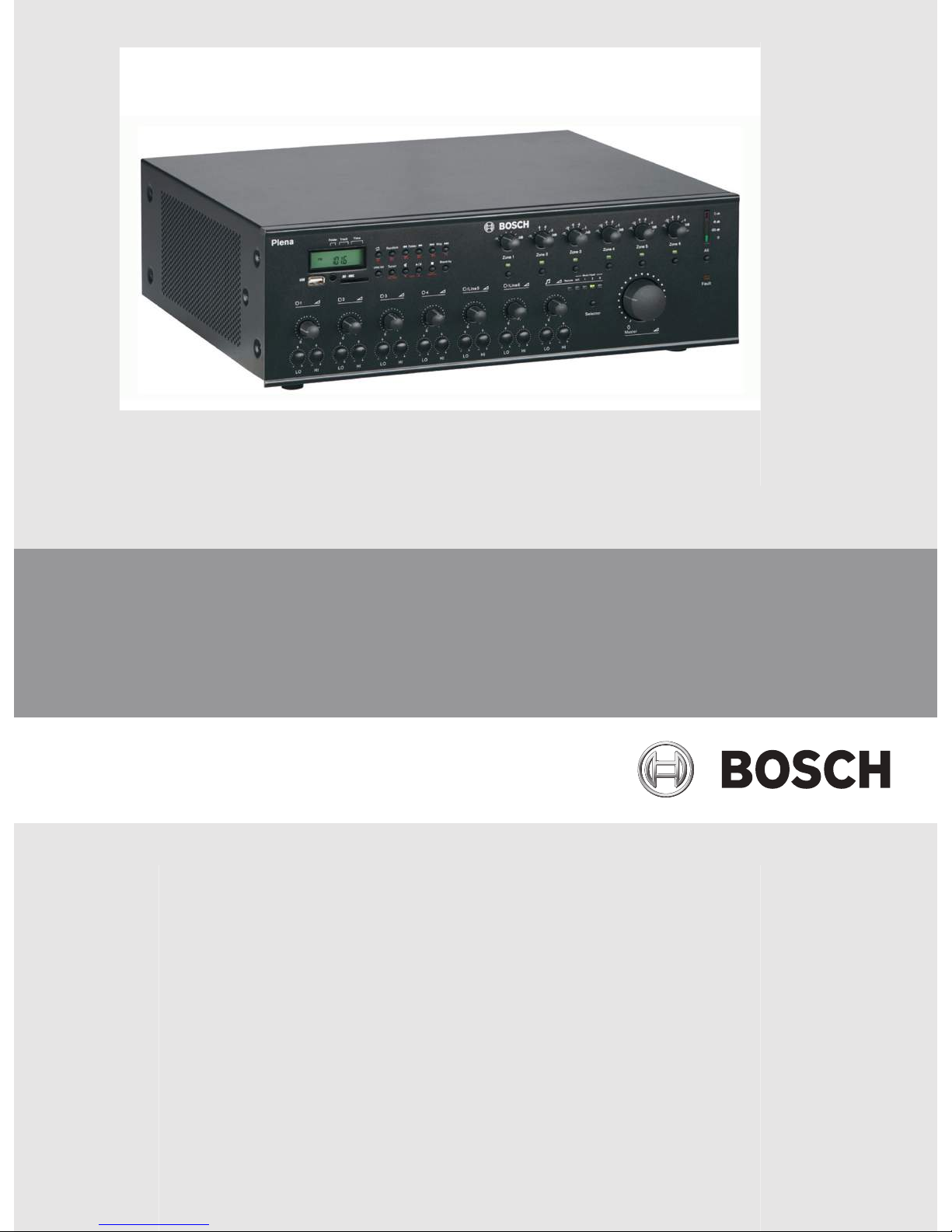
– PLN‑6AIO240 All‑in‑One Unit
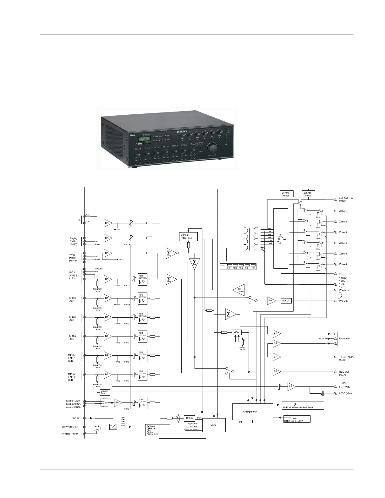
Figure 3.1: All‑in‑One Unit block diagram
3.2
Plena All-in-One System System Overview | en 9
Bosch Security Systems B.V. Installation and Operating Manual 2014.09 | V1.2 |
The All‑in‑One Unit is the main product of the All‑in‑One System and integrates the following
components:
– a 240 W mono mixer amplifier.
– SD and USB player that can play MP3 encoded files from SD and USB devices.
– a digitally controlled AM/FM-tuner for receiving radio stations.
Up to six microphones and three auxiliary source signals can be connected to the mixer
amplifier and mixed, with priority or VOX switching. The output signal can be routed to six
different zones with individual attenuation control. The unit can be extended with an
additional power amplifier, e.g. LBB1935/20, as a spare amplifier or for 2‑channel operation.
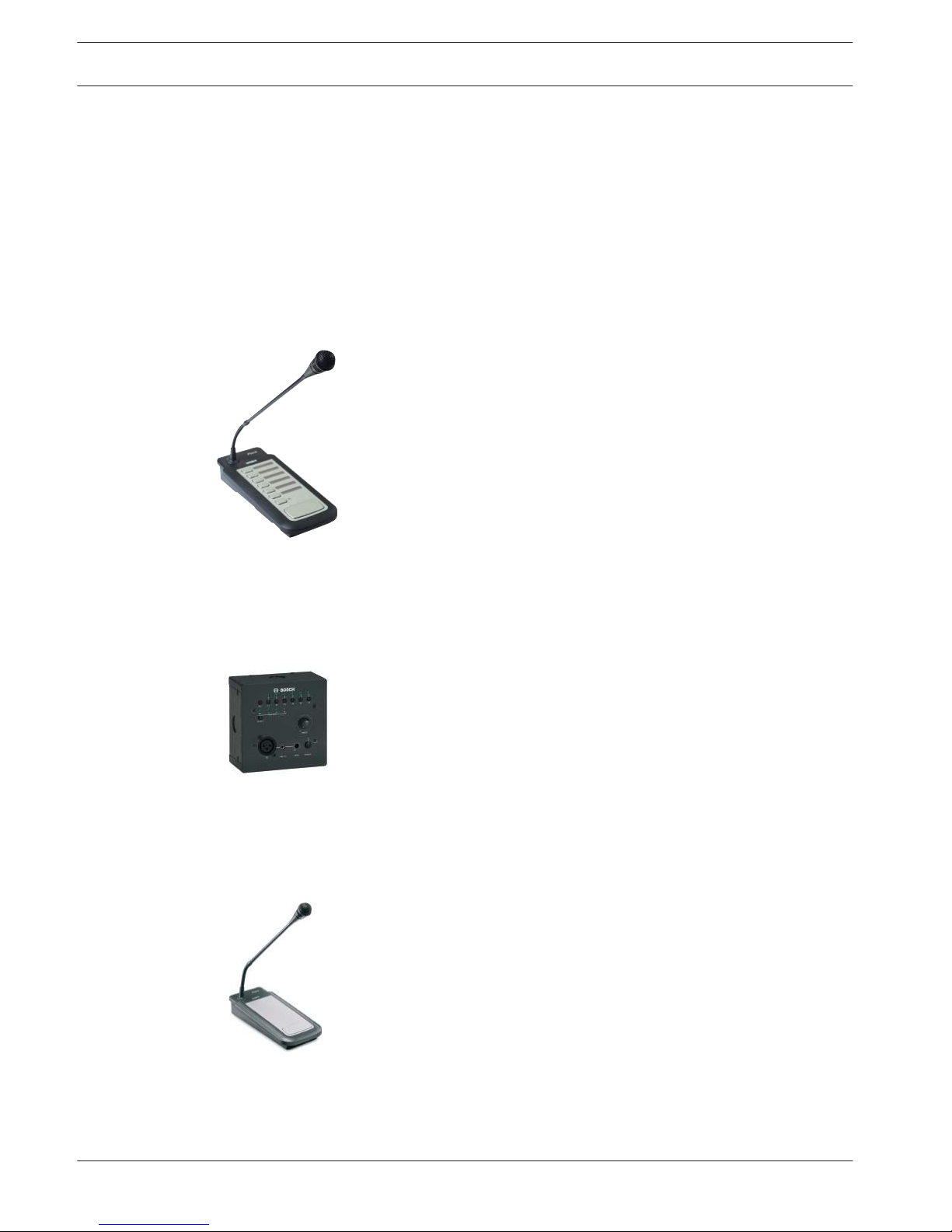
– PLN‑6CS Call Station
The PLN‑6CS Call Station is a remote device for making announcements to selected zones of
the All‑in‑One System. A maximum of six Call Stations can be connected in a daisy chain
configuration to the All‑in‑One Unit using Cat‑5 cables terminated with RJ45 connectors.
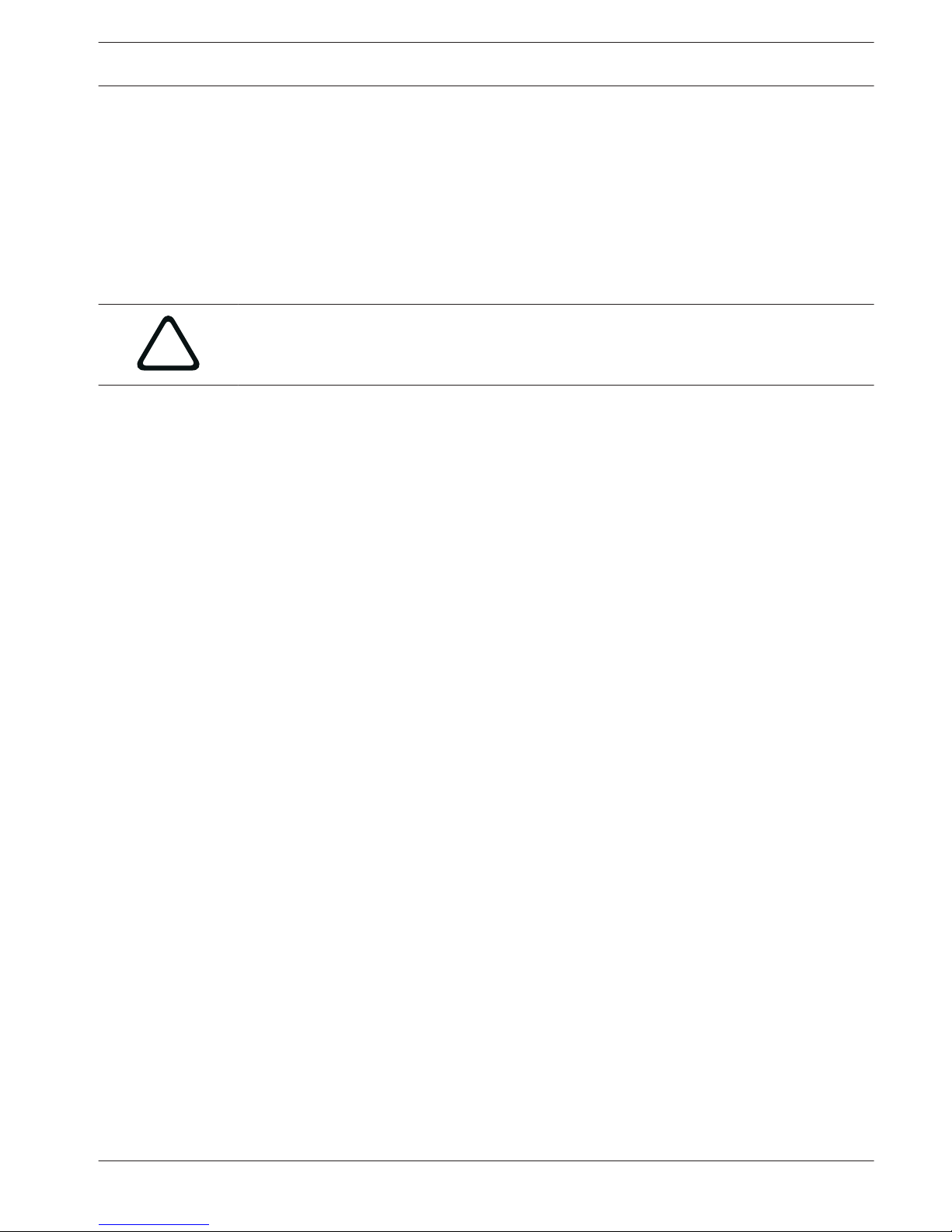
– PLN‑4S6Z Wall Panel
The PLN‑4S6Z Wall Panel is used to remotely control the All‑in‑One Unit. It is connected to the
All‑in‑One Unit using a Cat‑5 cable terminated with RJ45 connectors.
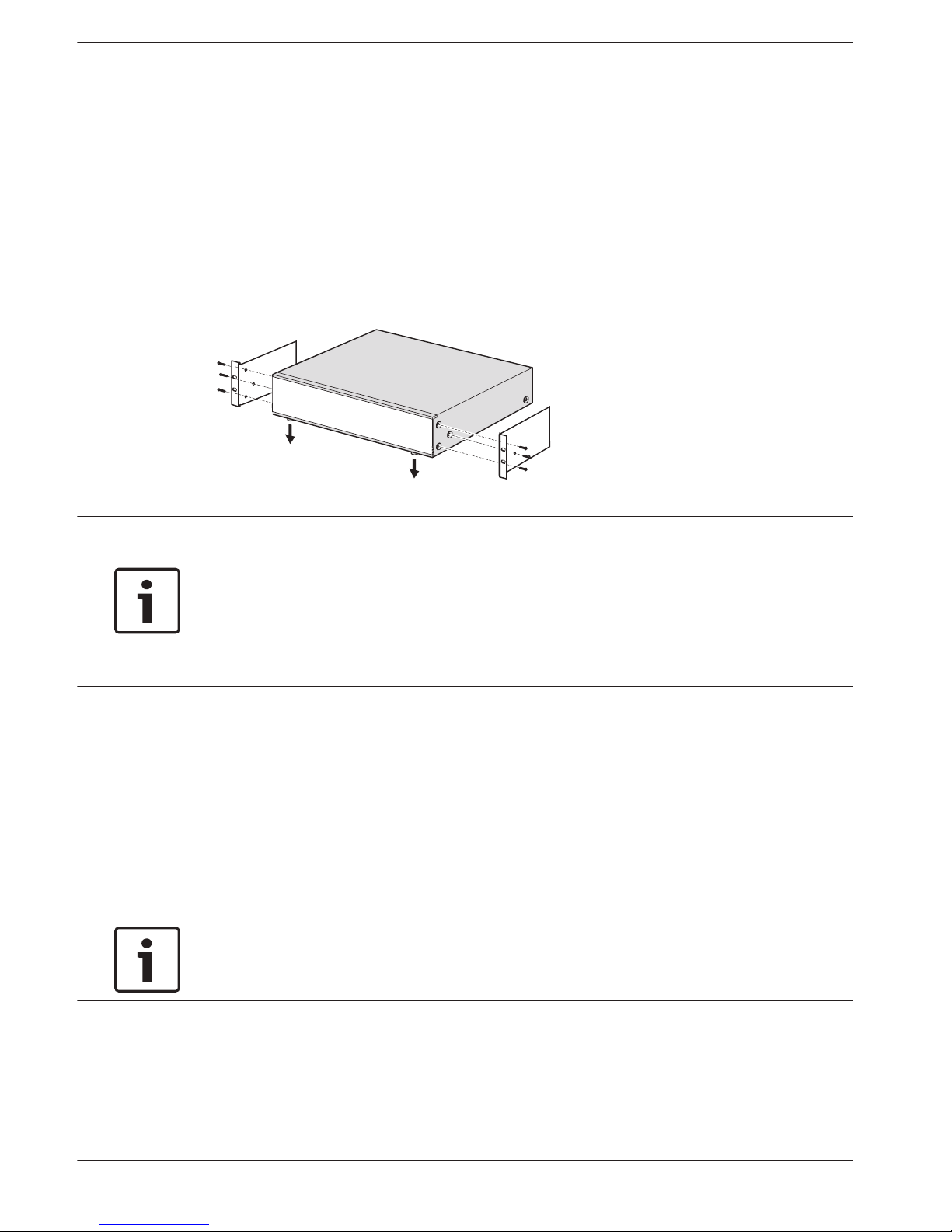
– PLE‑1CS or PLE‑1SCS Call Station
The PLE‑1CS or PLE‑1SCS Call Station is an all‑call call station that can be used with the
All‑in‑One Unit for making announcements without zone selection. It is connected to the
All‑in‑One Unit using a shielded Cat‑5 cable terminated with RJ45 connectors.
10 en | System Overview Plena All-in-One System
2014.09 | V1.2 | Installation and Operating Manual Bosch Security Systems B.V.
Packaging and transportation
Before using the Plena All‑in‑One System, read this section to make sure you have
all components for connecting and operating the system.
Unpacking
– This equipment should be unpacked and handled with care.
– If an item appears to be damaged, notify the shipper immediately.
– Carefully peel off the protective plastic film from the displays.
!
Caution!
Do not use sharp or pointed objects.
– If any items are missing, notify your Bosch representative.
– The original packaging is the safest container in which to transport products and can be
used to return products for service if necessary.
Delivered with products
PLN‑6AIO240 Plena All-in-One Unit
Quantity Component
1 All‑in‑One Unit
1 m Cat‑5 cable with RJ45 termination for adaptor
1 Adaptor to connect a PLE‑1CS or PLE‑1SCS desktop microphone via
shielded Cat‑5 wiring
1 AC power cord (for European mains sockets)
1 Safety Instructions
1 AM indoor antenna
1 Coax connector for FM antenna
1 Pair of brackets for 19“ rack installation
1 Remote control unit (without batteries)
1 Installation and Operating Manual
PLN‑6CS Plena All-in-One Call Station
Quantity
Component
1 All‑in‑One Call Station
1 m Cat‑5 cable with RJ45 plugs
1 Terminator plug
PLN‑4S6Z Plena All-in-One Wall Panel
Quantity
Component
1 All‑in‑One Wall Panel
1 m Cat‑5 cable with RJ45 plugs
4
4.1
4.2
Plena All-in-One System Packaging and transportation | en 11
Bosch Security Systems B.V. Installation and Operating Manual 2014.09 | V1.2 |
Installation
Install All-in-One Unit in 19“ rack (optional)
The unit is intended for tabletop use. However, the unit can also be mounted in a 19” rack. For
19" rack installation use:
– The 19” rack mounting brackets that are supplied with the product.
– The 6 screws and washers to replace the shorter screws that fix the cover to the chassis.
– Standard rack screws and cage nuts (not delivered with the product).
Figure 5.1: Install unit in a 19” rack
Notice!
If you install the unit in a 19” rack, make sure:
- the tabletop feet are removed from the bottom of the unit.
- warm air expelled from the side of the unit can flow away.
- the unit cannot exceed the maximum operating temperature (+45°C ambient).
- there is sufficient ventilation and enough room, about 10 cm / 4”, behind the unit for cables
and connections.
Install Call Station
1. The Call Station is used as a desktop device. Do not place this product where it is likely
to have liquid spilt on it.
2. When installing the Call Station, do not:
– exceed the cable manufactures’ “bend radius” specifications,
– install cabling in such a way that it becomes damaged or presents a hazard.
3. Make sure the RJ45 connectors have strong locking tabs, and cannot be inadvertently
pulled out once installed. Refer to Call Station connections, page 18.
Notice!
A maximum of six call stations can be configured for each All-in-One Unit.
The maximum cable distance from the All-in-One Unit to the last Call Station is 600 m.
5
5.1
5.2
12 en | Installation Plena All-in-One System
2014.09 | V1.2 | Installation and Operating Manual Bosch Security Systems B.V.

Install Wall Panel
The Wall Panel consists of a flat control panel and a rear mounting bracket, which is used for
installing the product on a wall or flat surface. Cable entry is possible at the rear and sides of
the mounting bracket.
This allows the mounting bracket to be used for:
– solid masonry walls, where cables run externally across the wall and enter the product
from the side, or
– frame constructions, where cables are inside the cavity and need to enter the product
from the rear.
1. Remove the four attachment screws on the control front panel to separate it from the
mounting bracket. Do not remove other screws from the mounting bracket. They are used
to secure components.
2. Gently remove the control panel from the mounting bracket and put it in a safe place.
Take care not to damage the printed circuit board on the back of the control panel.
3. Attach the mounting bracket to a flat surface:
– Make sure the RJ45 cable can easily enter the product.
– Make sure there are no electrical cables that will be damaged by the mounting
bracket attachment screws.
– Make sure the mounting bracket is level and straight before attaching it.
– Allow enough space around the mounting bracket so that the control panel can be
easily fitted.
4. Set the jumper on the rear of the control panel:
– Refer to Wall Panel configuration, page 28.
5. Feed the RJ45 cable through the mounting bracket and connect it to the RJ45 connector
at the rear of the control panel.
– To maximize the bend radius of the cable in the confined space it is strongly
recommended to use the shortest RJ45 connector possible.
– Make sure the All‑in‑One Unit is switched off before connecting the RJ45 cable.
– Refer to Wall Panel connections, page 20.
6. Gently position the control panel in the mounting bracket, taking care not to damage the
printed circuit board or the RJ45 cable.
7. Secure the control panel with the four attachment screws. Do not over-tighten.
5.3
Plena All-in-One System Installation | en 13
Bosch Security Systems B.V. Installation and Operating Manual 2014.09 | V1.2 |
Connection
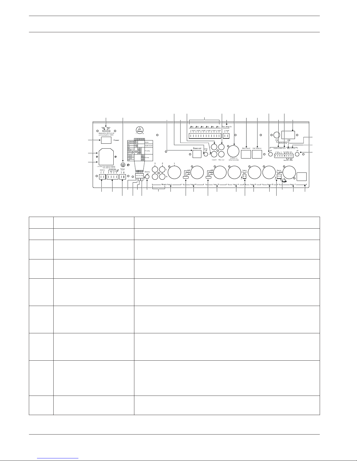
All‑in‑One Unit connections
The following figure lists all items on the rear panel of the All‑in‑One Unit. This section only
describes the items used for connecting the All‑in‑One Unit. For information on configuring the
unit, refer to All-in-One Unit configuration, page 21.
17 20
52
53
54
55
56
50 49
48 46
47
59
51
57
45
44
43
424138373534322221
16
18
19
30
40
3936333123 25
24
28
58
29
27
26
Figure 6.1: Rear panel
Number
Item Description
18 Mains power inlet Connection for mains power cord: 115/230 VAC ±15%, 50/60 Hz.
19 Mains line fuse holder Only replace a fuse with one of the same type, T6.3 A for 230 V or T10 A
for 115 V.
20 Ground chassis Screw terminal for a ground connection to a safety ground in case the
unit is not connected to a grounded electrical outlet
21 DC 24 V input terminal Connection for DC 24 V power source to the input terminal. Built‑in
reverse polarity protection. Input voltage range: 22‑28 Vdc, maximum
current 12 A at -3 dB output power.
22 Direct output terminals Amplifier output terminals that are not affected by the zone selectors
and zone level controls. The following output terminals are available:
0 V / 8 ohm / 70 V / 100 V. The outputs are short-circuit proof.
23 Remote on/off terminal If a DC 24 V (22‑28 Vdc) power source is applied, the unit is powered
on. To use this function correctly, the mains switch on the unit must be
set to OFF and the DC 24 V backup should not be used.
29 Music 2 and 3 inputs RCA sockets to connect external equipment. Stereo signals are
converted into mono.
– Music input 2 sensitivity: 500 mV, 10 kohm unbalanced.
– Music input 3 sensitivity: 300 mV, 10 kohm unbalanced.
30 Music input 1 TRS-jack/XLR connector to connect an external mono music source.
– Input 1 sensitivity: 500 mV, 10 kohm unbalanced.
6
6.1
14 en | Connection Plena All-in-One System
2014.09 | V1.2 | Installation and Operating Manual Bosch Security Systems B.V.

Number Item Description
32 Input 6 – Microphone or Line input 6, with TRS-jack / XLR balanced signal
input connector.
– Microphone input 6 sensitivity: 1.5 mV, 600 ohm balanced.
– Line input 6 sensitivity: 200 mV, 10 kohm balanced.
34 Input 5: – Microphone or Line input 5, with TRS-jack / XLR balanced signal
input connector.
– Microphone input 5 sensitivity: 1.5 mV, 600 ohm balanced.
– Line input 5 sensitivity: 200 mV, 10 kohm balanced.
35 Input 4 – Microphone input 4, with TRS-jack / XLR balanced signal input
connector.
– Microphone input 4 sensitivity: 1.5 mV, 600 ohm balanced.
37 Input 3 – Microphone input 3, with TRS-jack / XLR balanced signal input
connector.
– Microphone input 3 sensitivity: 1.5 mV, 600 ohm balanced.
38 Input 2 – Microphone input 2, with TRS-jack / XLR balanced signal input
connector.
– Microphone input 2 sensitivity: 1.5mV, 600 ohm balanced.
41 Input 1 – Microphone input 1 with TRS-jack / XLR balanced signal input
connector.
– Microphone input 1 sensitivity: 1.5 mV, 600 ohm balanced
42 Input 1 RJ45 connector This input is intended for a PLE-1CS or PLE-1SCS all-call Call Station,
which is connected with a Cat-5 cable and adapter box (supplied with
the unit). This allows for different length standard Cat-5 cables to be
used.
The PIN assignments of the RJ45 are as follows:
– Pin 1: Audio+
– Pin 2: Audio– Pin 3: Ground
– Pin 4: Trigger+
– Pin 5: Trigger- (Ground)
– Pins 6‑8: Not connected
A contact closure between pin 4 and 5 will activate the chime signal and
give priority to input 1. It will mute signals on other inputs, except for
the Telephone/Emergency input (46/47). The PTT switch (40) must be
ON.
44
8Ω MOH output 1 W, unbalanced Music-on-Hold output terminal for monitoring of the
internal music source or Music inputs 1-3 signals, selected by the music
source selector (7).
45 Balanced MOH output 600 ohm, 1 Vrms, transformer isolated balanced Music-on-Hold signal
for monitoring of the internal music source or Music inputs 1-3 signals,
selected by the music source selector (7).
46 Telephone/Emergency 100 V
input
A balanced 100 V input, compatible with loudspeaker line signals. This
input has a gate function (VOX); when the signal level exceeds a -10 dB
level, it gets the highest priority and overrides all other inputs.
Plena All-in-One System Connection | en 15
Bosch Security Systems B.V. Installation and Operating Manual 2014.09 | V1.2 |

Number Item Description
47 Telephone/Emergency input The same as input (46), but with an input sensitivity of 100 mV,
impedance 600 ohm.
49 Call station connector RJ45 connector for up to six PLN-6CS call stations connected in
cascade. Ordinary shielded or unshielded Cat-5 cables can be used for
interconnection. Maximum length to the last call station is 600 m. Pin
assignment of this connector:
– Pin 1: Audio IN+
– Pin 2: Audio IN– Pin 3: Ground
– Pin 4: Not connected
– Pin 5: Not connected
– Pin 6: + 24 Vdc < 800 mA
– Pin 7: RS485+
– Pin 8: RS485-
50
Wall Panel connector RJ45 connector for one PLN-4S6Z Wall Panel. Ordinary shielded or
unshielded Cat-5 cables can be used for interconnection. Pin
assignment of this connector:
– Pin 1: Audio IN+
– Pin 2: Audio IN– Pin 3: Ground
– Pin 4: Not connected
– Pin 5: Not connected
– Pin 6: + 24 VDC < 800 mA
– Pin 7: RS485+
– Pin 8: RS485-
51
Output for external amplifier 0 dBV, 600 ohm balanced output on XLR female connector for
connection to an external amplifier. To be used as a second amplifier in
case of dual‑channel mode or as a spare amplifier.
52 Rec out Record output on RCA socket.
– This output provides a 350 mV, unbalanced, mono output signal
before the MASTER volume control.
53 Insert in Input of the power amplifier stage. In most cases this input is directly
connected to the “Insert out” terminal (54), but you can connect an
equalizer or other audio equipment between “Insert out” and “Insert
in”.
– 0 dBV, 10 kohm unbalanced input RCA socket.
54 Insert out The output of internal pre-amplifier stage.
– 0 dBV, 600 ohm unbalanced input RCA socket.
56 RESERVED Not used.
57 Ext Amp in 0-100V terminal The output of the optional external power amplifier is connected to this
input. The external amplifier can be used as spare amplifier or as a
second amplifier in dual‑channel mode.
– Current rating maximum 7 A (50 Hz to 20 kHz).
16 en | Connection Plena All-in-One System
2014.09 | V1.2 | Installation and Operating Manual Bosch Security Systems B.V.
 Loading...