


Bosch MIC IP starlight 7000i Installation Manual

MIC IP starlight 7000i
en
Installation Manual


MIC IP starlight 7000i Table of contents | en 3
Table of contents
1
1.1 About this Manual 4
1.2 Legal Information 4
1.3 Safety Precautions 5
1.4 Important Safety Instructions 6
1.5 Important Notices 8
1.6 Important Notices - Illumination Safety 11
1.7 Customer Support and Service 12
2
2.1 Configuration with Project Assistant app 13
3
4
5
5.1 Mounting Location and Orientation Options 17
5.2 Mounting Options 18
5.3 Mounting Bracket Options 20
5.4 Considerations for Mounting the Camera in Inverted Orientation 22
6
7
8
9
10
11
11.1 About Camera Power and Control 45
11.2 Power Source Options 45
11.3 Ethernet Connections 46
11.4 Camera Connections 46
11.5 Connect the Camera to the Network 47
12
12.1 Typical IP Configuration with High PoE midspan (no I/O connections) 49
12.2 Typical Configuration with MIC-ALM-WAS-24 50
12.3 Typical IP Configuration with VJC-7000-90 51
13
14
15
16
17
18
Safety 4
Introduction 13
Product Description 14
Overview of Installation Steps 16
Mounting 17
(Optional) Configuration Programming in the Shipping Box 24
(Optional) Configuration Programming on a Temporary Table-top Stand 25
(Optional) Installing the Illuminator 26
(Optional) Canting the Camera 33
Replacing a wiper assembly 38
Connections 45
Typical System Configurations 49
Troubleshooting 52
Maintenance 53
Disposal 54
Technical data 55
Best Practices for Outdoor Installation 56
Error Codes 58
Bosch Security Systems Installation Manual 2019-11 | 2.1 |

4 en | Safety MIC IP starlight 7000i
1 Safety
1.1 About this Manual
This manual has been compiled with great care and the information it contains has been
thoroughly verified. The text was complete and correct at the time of printing. Because of the
ongoing development of products, the content of the manual may change without notice.
Bosch Security Systems accepts no liability for damage resulting directly or indirectly from
faults, incompleteness, or discrepancies between the manual and the product described.
1.2 Legal Information
Copyright
This manual is the intellectual property of Bosch Security Systems, and is protected by
copyright. All rights reserved.
Trademarks
All hardware and software product names used in this document are likely to be registered
trademarks and must be treated accordingly.
2019-11 | 2.1 | Installation Manual Bosch Security Systems
MIC IP starlight 7000i Safety | en 5
!
!
1.3 Safety Precautions
In this manual, the following symbols and notations are used to draw attention to special
situations:
Danger!
High risk: This symbol indicates an imminently hazardous situation such as “Dangerous
Voltage” inside the product. If not avoided, this will result in an electrical shock, serious
bodily injury, or death.
Warning!
Medium risk: Indicates a potentially hazardous situation. If not avoided, this may result in
minor or moderate injury.
Caution!
Low risk: Indicates a potentially hazardous situation. If not avoided, this may result in
property damage or risk of damage to the unit.
Notice!
This symbol indicates information or a company policy that relates directly or indirectly to the
safety of personnel or protection of property.
Bosch Security Systems Installation Manual 2019-11 | 2.1 |
6 en | Safety MIC IP starlight 7000i
!
!
!
!
!
!
1.4 Important Safety Instructions
Read, follow, and retain all of the following safety instructions. Heed all warnings on the unit
and in the operating instructions before operation.
Caution!
TO REDUCE THE RISK OF ELECTRIC SHOCK, DISCONNECT THE POWER SOURCE WHILE
INSTALLING THE DEVICE.
Caution!
Installation must be made by qualified personnel and conform to ANSI/NFPA 70 (the National
Electrical Code® (NEC)), Canadian Electrical Code, Part I (also called CE Code or CSA C22.1),
and all applicable local codes. Bosch Security Systems accepts no liability for any damages or
losses caused by incorrect or improper installation.
Warning!
INSTALL EXTERNAL INTERCONNECTING CABLES IN ACCORDANCE TO NEC, ANSI/NFPA70
(FOR US APPLICATION) AND CANADIAN ELECTRICAL CODE, PART I, CSA C22.1 (FOR CAN
APPLICATION) AND IN ACCORDANCE TO LOCAL COUNTRY CODES FOR ALL OTHER
COUNTRIES. BRANCH CIRCUIT PROTECTION INCORPORATING A 20 A, 2-POLE LISTED
CIRCUIT BREAKER OR BRANCH RATED FUSES ARE REQUIRED AS PART OF THE BUILDING
INSTALLATION. A READILY ACCESSIBLE 2-POLE DISCONNECT DEVICE WITH A CONTACT
SEPARATION OF AT LEAST 3 mm MUST BE INCORPORATED.
Warning!
ROUTING OF EXTERNAL WIRING MUST BE DONE THROUGH A PERMANENTLY EARTHED
METAL CONDUIT.
Warning!
THE CAMERA MUST BE MOUNTED DIRECTLY AND PERMANENTLY TO A NON-COMBUSTIBLE
SURFACE.
Warning!
Risk of bodily injury
Do not put a canted (45°) camera in an upright position on the camera base or on an
unsecured DCA. In this position, the camera can fall over and can cause injury or be damaged.
Put the canted camera on its side until installation.
– Do not open the camera unit. Doing so will invalidate the warranty.
– Use common-sense safety precautions, especially in situations where there could be risk
of injury if any part of the assembly becomes detached and falls. Bosch recommends
using the hinged DCA, which allows installers to “hang” the MIC camera temporarily on
the DCA to make electrical connections, before bolting the camera to the DCA.
– Ensure that the unit case is properly earthed. If the product is at risk of being struck by
lightning, ensure that earth bonding connections are made correctly to the mounting of
the base of the unit.
– Do not point the camera at the sun. Bosch Security Systems will not be liable for any
damage to cameras that have been pointed directly at the sun.
2019-11 | 2.1 | Installation Manual Bosch Security Systems
MIC IP starlight 7000i Safety | en 7
!
!
– Before transporting, supply power to the camera and rotate the camera head so that the
window points toward the base. This position of the camera head will help to protect the
wiper and the window during transit.
– Make sure that the installation conditions comply with the specified stresses of vibration
and shock as mentioned in the datasheet.
Warning!
Do not manually back drive the camera
The motor/gear head combinations used in the MIC cameras were designed to provide
smooth pan/tilt movement of the camera during powered operation. The gear heads were not
specifically designed to be manually “back-driven” under any circumstance.
Although it might be possible to do so on unpowered units, there is no guarantee that “backdriving” will be possible on every unit. Some units may even enter a “locked-up” mechanical
state.
If the camera becomes “locked-up,” simply apply power to the camera. The pan/tilt functions
of the camera should now operate properly.
Warning!
Moving parts!
Moving parts may result in risk of injury, therefore, the device should be mounted so that it is
accessible only to the technician/installer.
Notice!
Risk of injury or damage
To prevent injury to your hands or damage to the wiper, do not touch the wiper with your
hands, especially when the wiper is moving.
Notice!
Always use a shielded twisted pair (STP) connection cable and a shielded RJ45 network cable
connector where the camera is used outdoors or the network cable is routed outdoors.
Always use shielded cables/connectors in demanding indoor electrical environments where
the network cable is located in parallel with electrical mains supply cables, or where large
inductive loads such as motors or contactors are near the camera or its cable.
Notice!
Bosch recommends the use of surge/lightning protection devices (sourced locally) to protect
network and power cables and the camera installation site. Refer to NFPA 780, Class 1 & 2,
UL96A, or the equivalent code appropriate for your country/region, and to local building
codes. Refer also to the installation instructions of each device (surge protector where the
cable enters the building, midspan, and camera).
Notice!
Outdoor installation
For details about the proper configuration for installing your camera outdoors with surge and
lightning protection, refer to Best Practices for Outdoor Installation, page 56.
Notice!
To maintain the Type 6P rating when the camera is mounted to a MIC-DCA, installers must
make sure that the user-supplied cable glands or conduit connections have Type 6P ratings.
Bosch Security Systems Installation Manual 2019-11 | 2.1 |
8 en | Safety MIC IP starlight 7000i
1.5 Important Notices
For use in China: CHINA ROHS DISCLOSURE TABLE
Moving cameras
Hazardous substance table according to SJ/T 11364-2014
Pb
(Pb)
Housing & enclosures X O O O O O
PCBA with connectors X O X O O O
Cable assemblies O O O O O O
Image sensor assembly X O X O O O
Lens assembly X O X O O O
PT Motor control assembly X O X O O O
Fan assembly X O X O O O
This table was created according to the provisions of SJ/T 11364
O: The content of such hazardous substance in all homogeneous materials of such
component is below the limit defined in GB/T 26572
X: The content of such hazardous substance in a certain homogeneous material is above the
limit defined in GB/T 26572
Hg
(Hg)
Cd
(Cd)
Cr 6+
(Cr 6+)
PBB
(PBB)
PBDE
(PBDE)
The manufacturing datecodes of the products are explained in:
http://www.boschsecurity.com/datecodes/
Notice!
This device is intended for use in public areas only.
U.S. federal law strictly prohibits surreptitious recording of oral communications.
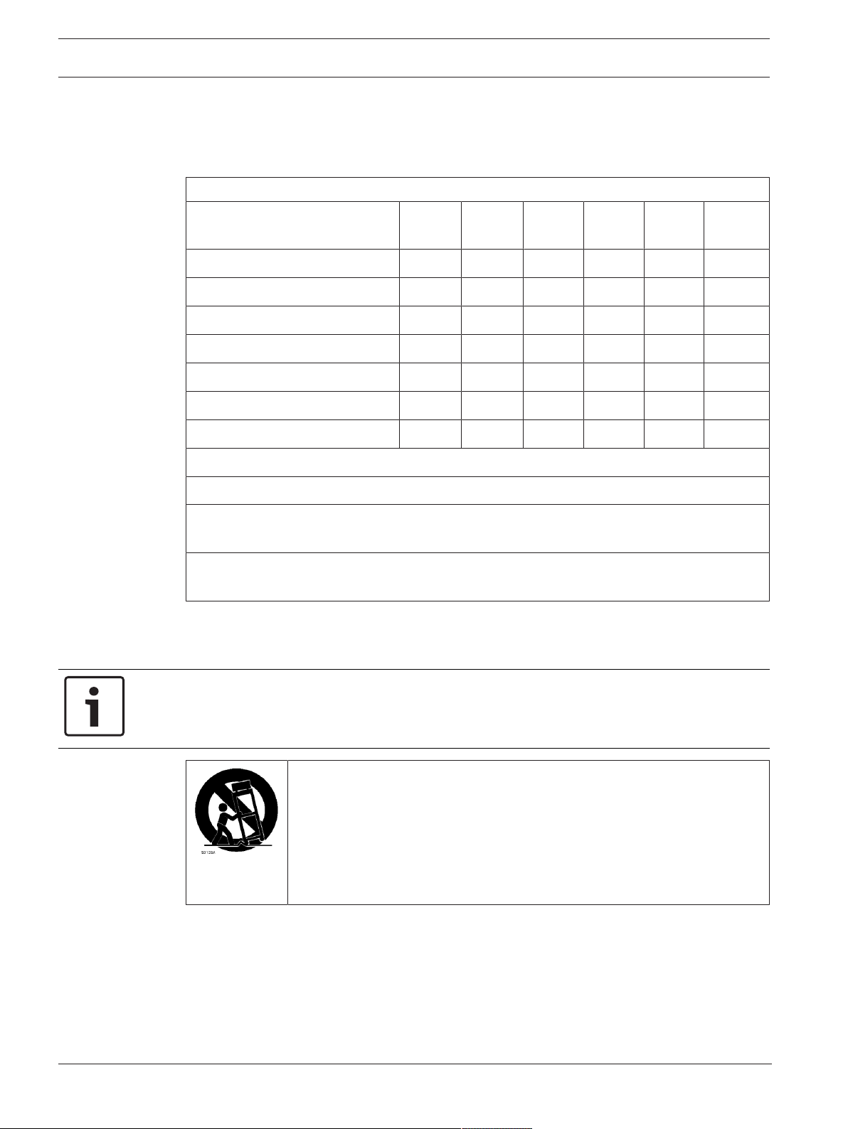
Accessories - Do not place this unit on an unstable stand, tripod, bracket, or
mount. The unit may fall, causing serious injury and/or serious damage to
the unit. Use only with mounting solutions specified by the manufacturer.
When a cart is used, use caution and care when moving the cart/unit
combination to avoid injury from tip-over. Quick stops, excessive force, or
uneven surfaces may cause the cart/unit combination to overturn. Mount the
unit per the installation instructions.
Adjustment of controls - Adjust only those controls specified in the operating instructions.
Improper adjustment of other controls may cause damage to the unit.
All-pole power switch - Incorporate an all-pole power switch, with a contact separation of at
least 3 mm, into the electrical installation of the building. If the camera requires service, use
this all-pole switch as the main disconnect device for switching off the voltage to the unit.
Camera signal - Protect the cable with a primary protector if the camera signal is beyond 140
feet, in accordance with NEC800 (CEC Section 60).
2019-11 | 2.1 | Installation Manual Bosch Security Systems

MIC IP starlight 7000i Safety | en 9
Environmental statement - Bosch has a strong commitment towards the environment. This
device has been designed to respect the environment as much as possible.
Electrostatic-sensitive device - Use proper ESD safety precautions when handling the camera
to avoid electrostatic discharge.
Fuse rating - For security protection of the device, the branch circuit protection must be
secured with a maximum fuse rating of 16A. This must be in accordance with NEC800 (CEC
Section 60).
Grounding:
- Connect outdoor equipment to the unit's inputs only after this unit has had its ground
terminal connected properly to a ground source.
- Disconnect the unit's input connectors from outdoor equipment before disconnecting the
grounding terminal.
- Follow proper safety precautions such as grounding for any outdoor device connected to this
unit.
U.S.A. models only - Section 810 of the National Electrical Code, ANSI/NFPA No.70, provides
information regarding proper grounding of the mount and supporting structure, size of
grounding conductors, location of discharge unit, connection to grounding electrodes, and
requirements for the grounding electrode.
Refer to the section ”Best Practices for Outdoor Installation” of the manual for more
information on outdoor installations.
Heat sources - Do not install unit near any heat sources such as radiators, heaters, or other
equipment (including amplifiers) that produce heat.
Moving - Before moving the unit, disconnect both the 24 VAC connection and the Ethernet
cable connection (if using PoE).
Outdoor signals - The installation for outdoor signals, especially regarding clearance from
power and lightning conductors and transient protection, must be in accordance with NEC725
and NEC800 (CEC Rule 16-224 and CEC Section 60).
Refer to the ”Best Practices for Outdoor Installation, page 56” section of the manual for more
information on outdoor installations.
Permanently connected equipment - Incorporate a readily accessible disconnect device in the
building installation wiring.
Power lines - Do not locate the camera near overhead power lines, power circuits, or
electrical lights, nor where it may contact such power lines, circuits, or lights.
Damage requiring service – Unplug the devices from the main AC power source and refer
servicing to qualified service personnel whenever any damage to the device has occurred,
such as:
- the power supply cable is damaged;
- an object has fallen on the device;
- the device has been dropped, or its enclosure has been damaged;
- the device does not operate normally when the user follows the operating instructions
correctly.
Servicing - Do not attempt to service this device yourself. Refer all servicing to qualified
service personnel.
This device has no user-serviceable internal parts.
Notice!
This is a class A product. In a domestic environment this product may cause radio
interference, in which case the user may be required to take adequate measures.
Bosch Security Systems Installation Manual 2019-11 | 2.1 |

10 en | Safety MIC IP starlight 7000i
Note: Changes or modifications not expressly approved by Bosch could void the user’s
authority to operate the equipment.
FCC & ICES Information
(U.S.A. and Canadian Models Only)
This device complies with part 15 of the FCC Rules. Operation is subject to the following
conditions:
– this device may not cause harmful interference, and
– this device must accept any interference received, including interference that may cause
undesired operation.
NOTE: This equipment has been tested and found to comply with the limits for a Class A
digital device, pursuant to Part 15 of the FCC Rules and ICES-003 of Industry Canada. These
limits are designed to provide reasonable protection against harmful interference when the
equipment is operated in a commercial environment. This equipment generates, uses, and
radiates radio frequency energy and, if not installed and used in accordance with the
instruction manual, may cause harmful interference to radio communications. Operation of
this equipment in a residential area is likely to cause harmful interference, in which case the
user will be required to correct the interference at his expense.
Intentional or unintentional modifications, not expressly approved by the party responsible for
compliance, shall not be made. Any such modifications could void the user's authority to
operate the equipment. If necessary, the user should consult the dealer or an experienced
radio/television technician for corrective action.
Responsible party
Bosch Security Systems, Inc.
130 Perinton Parkway
14450 Fairport, NY, USA
www.boschsecurity.us
Refer to
– Best Practices for Outdoor Installation, page 56
2019-11 | 2.1 | Installation Manual Bosch Security Systems

MIC IP starlight 7000i Safety | en 11
1.6 Important Notices - Illumination Safety
The text in this section applies only to cameras which have the optional illuminator accessory.
The IEC 62471 provides the methods to determine the risk group of any lamp or any product
incorporating a lamp. The risk groups in IEC 62471 indicate the degree of risk from potential
optical radiation hazards. The risk groups were developed based upon decades of lamp use
experience and the analysis of accidental injuries related to optical radiation emission.
EXEMPT Group – no optical hazard is considered reasonably foreseeable, even for
continuous, unrestricted use. Typical examples are most frosted incandescent lamps and
fluorescent lamps used in domestic applications.
Risk Group 1 – products are safe for most use applications, except for very prolonged
exposures where direct ocular exposures may be expected. An example of Risk Group 1 is a
domestic battery operated torch (flashlight).
Exposure Hazard Value (EHV) is a ratio of the Exposure Level (distance, exposure time) to
Exposure Limit Value (ELV). When EHV is greater than 1, the device has exceeded the
Exposure Limit Values for a particular Risk Group. The ELV is the level where optical radiation
to the eye or skin is not expected to result in adverse biological effects.
The Hazard Distance (HD) is the distance from the source at which the Exposure Level equals
the appropriate ELV. In other words, when EHV=1 for a particular Risk Group.
Regarding the Cornea / Lens infrared hazard of this product, the Exposure Hazard Value (EHV)
at a test distance of 200mm is 2.19 based on EXEMPT Group exposure limits. The EHV based
on Risk Group 1 limits is 0.386. The HD for the Exempt Group is 297 mm.
Regarding the Retinal Blue Light hazard, the EHV is 22.9 based on the EXEMPT Group
exposure limits and a test distance of 200 mm. The EHV based on Risk Group 1 limits is 0.266.
The HD for the Exempt Group is 2675 mm.
These values have been summarized in the table below:
EXEMPT Group Limits Risk Group 1 Limits
Hazard
Cornea / Lens
Infrared Hazard
Retinal Blue Light
Hazard
Bosch Security Systems Installation Manual 2019-11 | 2.1 |
t, duration d, distance EHV t, duration d, distance EHV
1000 s
Hazard
Distance
10,000 s
Hazard
Distance
200 mm
279 mm
200 mm
2675 mm
2.19 100 s 200 mm 0.386
22.9 100s 200 mm 0.266

12 en | Safety MIC IP starlight 7000i
1.7 Customer Support and Service
If this unit needs service, contact the nearest Bosch Security Systems Service Center for
authorization to return and shipping instructions.
USA
Telephone: 800-366-2283
Fax: 800-366-1329
Email: cctv.repair@us.bosch.com
Customer Service
Telephone: 888-289-0096
Fax: 585-223-9180
Email: security.sales@us.bosch.com
Technical Support
Telephone: 800-326-1450
Fax: 717-735-6560
Email: technical.support@us.bosch.com
Canada
Telephone: 514-738-2434
Fax: 514-738-8480
Europe, Middle East, Africa, and Asia Pacific Regions
Please contact your local distributor or Bosch sales office. Use this link:
https://www.boschsecurity.com/corporate/where-to-buy/index.html
More Information
For more information, please contact the nearest Bosch Security Systems location or visit
www.boschsecurity.com.
2019-11 | 2.1 | Installation Manual Bosch Security Systems
MIC IP starlight 7000i Introduction | en 13
!
2 Introduction
– This equipment should be unpacked and handled with care. Check the exterior of the
packaging for visible damage. If an item appears to have been damaged in shipment,
notify the shipper immediately.
– Verify that all the parts listed in the Parts List below are included. If any items are
missing, notify your Bosch Security Systems Sales or Customer Service Representative.
– Do not use this product if any component appears to be damaged. Please contact Bosch
Security Systems in the event of damaged goods.
– The original packing carton (if undamaged) is the safest container in which to transport
the unit and must be used if returning the unit for service. Save it for possible future use.
Caution!
Take extra care lifting or moving MIC cameras because of their weight.
The MIC packaging is designed:
– to allow installers to configure the camera inside the shipping box.
– to provide a temporary table-top or desk-top stand.
2.1 Configuration with Project Assistant app
You can also use the Project Assistant app to complete the initial configuration of the camera.
In order to use this device with the Project Assistant app by Bosch, you must download the
app from the Bosch Download Store, from Google Play, or from the Apple Store.
You can access the app in several ways:
– Scan the QR code from the QIG.
– From www.boschsecurity.com, select Support > Apps and Tools > Online Apps - Video >
Bosch Project Assistant app. Select the appropriate operating system, and then click the
appropriate button to download and install the app.
– From Google Play Store (play.google.com), search for Bosch Project Assistant. Select the
app from the list. Click the Install button.
– From Apple Store (itunes.apple.com), search for Bosch Project Assistant. Select the app
from the list. Click the appropriate button to download and install the app.
Bosch Security Systems Installation Manual 2019-11 | 2.1 |

14 en | Product Description MIC IP starlight 7000i
3 Product Description
The camera’s ruggedized design meets customer expectations in demanding environments
that exceed the capabilities of conventional IP cameras. Even in installations subject to harsh
shock/vibration conditions and/or extreme weather, the camera provides high-quality video
images.
– Make sure that the installation conditions comply with the specified stresses of vibration
and shock as mentioned in the datasheet.
The MIC IP starlight 7000i camera is an advanced PTZ surveillance platform for mission-critical
applications. With starlight imaging technology and excellent low-light sensitivity, the MIC IP
starlight 7000i camera is the perfect solution for robust and high-quality imaging needs.
The camera also has a 30x optical zoom (12x digital) and flexible, field-selectable mounting
orientations (upright, inverted, or canted) to achieve the perfect field of view.
A long-life silicone wiper blade mounted on a spring-loaded arm is standard on all MIC
cameras.
The following table identifies the optional accessories for MIC cameras. Refer to the
datasheets of each accessory for details. Some accessories may not be available in all regions.
Accessories Description Accessories Description
MIC-DCA-H
- MIC-DCA-HB
- MIC-DCA-HW
- MIC-DCA-HG
- MIC-DCA-HBA
- MIC-DCA-HWA
- MIC-DCA-HGA
MIC-CMB
- MIC-CMB-BD
- MIC-CMB-WD
- MIC-CMB-MG
MIC-WMB
- MIC-WMB-BD
- MIC-WMB-WD
- MIC-WMB-MG
NPD-9501A 95 W midspan MIC-WKT-IR Washer Kit
VG4-A-PSU1
VG4-A-PSU2
NPD-6001B 60 W midspan [Not for use with
Hinged Deep Conduit Adapter in
Black
White
Grey
Black with M25 to ¾” adapter
White with M25 to ¾” adapter
Grey with M25 to ¾” adapter
Corner Mount Bracket in
Black
White
Grey
Wall Mount Bracket in
Black
White
Grey
24 VAC (96 VA) power supply MIC-ALM-WAS-24 Alarm and washer interface
the illuminator accessory.]
MIC-SCA
- MIC-SCA-BD
- MIC-SCA-WD
- MIC-SCA-MG
MIC-SPR
- MIC-SPR-BD
- MIC-SPR-WD
- MIC-SPR-MG
MIC-PMB Pole Mount Bracket (stainless
VJC-7000-90 VIDEOJET connect 7000 (Full-
Shallow Conduit Adapter in
Black
White
Grey
Spreader Plate in
Black
White
Grey
steel only)
accessory unit
featured network interface unit/
power supply)
MIC-IP67-5PK MIC7000 IP67 Connector Kit MIC-67SUNSHLD Sunshield (white only)
MIC-ILx-300 User-installable illuminator
accessory specifically for MIC IP
starlight 7000i cameras, in
2019-11 | 2.1 | Installation Manual Bosch Security Systems
MVS-FCOM-PRCL Serial protocol license for IP cameras

MIC IP starlight 7000i Product Description | en 15
- MIC-ILB-300
- MIC-ILW-300
- MIC-ILG-300
Black
White
Grey
Bosch Security Systems Installation Manual 2019-11 | 2.1 |
16 en | Overview of Installation Steps MIC IP starlight 7000i
!
!
4 Overview of Installation Steps
Caution!
Installation must be made by qualified personnel and conform to ANSI/NFPA 70 (the National
Electrical Code® (NEC)), Canadian Electrical Code, Part I (also called CE Code or CSA C22.1),
and all applicable local codes. Bosch Security Systems accepts no liability for any damages or
losses caused by incorrect or improper installation.
Caution!
ELECTRIC SHOCK HAZARD
To reduce the risk of electric shock, disconnect power to the camera and/or to the power
supply unit before moving the camera, before installing any accessories, and before mounting
the camera.
Before you install your MIC camera, inspect the camera for any scratches or damage to the
surface finish/paint. If you notice damage to the paint, return the unit for a replacement.
1. Select the Mounting Location and Orientation.
2. Install the appropriate power supply--VIDEOJET connect (VJC-7000-90), 24 VAC (VG4-APSU1 or VG4-A-PSU2)--or midspan (60 W version or 95 W version), and/or the alarm/washer
interface (MIC-ALM-WAS-24) (all sold separately) as necessary. Refer to the Installation
Manual of the appropriate device for installation instructions.
3. Install grounded metal conduit (user-supplied) to the MIC DCA (sold separately) (and to the
PSU if necessary), install wiring (user-supplied), and then make the necessary connections for
power, telemetry, and video.
4. (Optional) Install the Illuminator Accessory. (Illuminator accessory sold separately.)
5. (Optional) Install the sunshield. (Sunshield sold separately.)
6. Install the Camera on the MIC-DCA.
6. Install the Camera Directly to a Mounting Surface.
7. Connections, page 45.
8. (Optional) (Optional) Canting the Camera, page 33.
2019-11 | 2.1 | Installation Manual Bosch Security Systems

MIC IP starlight 7000i Mounting | en 17
5 Mounting
5.1 Mounting Location and Orientation Options
MIC cameras are designed for easy installation in various locations such as directly onto
buildings and poles suitable to support CCTV equipment.
Select a secure installation location and mounting orientation for the device. Ideally, this is a
location where the device cannot be interfered with either intentionally or accidentally.
Select a location where the MIC camera will not touch materials such as steel straps or
cables.
You can install the camera:
– onto a MIC-DCA or a MIC wall mount (MIC-WMB) with a MIC shallow conduit adapter
(MIC-SCA). (Never install the wall mount only.)
or
– directly to a mounting surface using the supplied base gasket and the appropriate
connector kit (sold separately):
– MIC-IP67-5PK MIC7000 IP67 Connector Kit
To have an installation rated IP67, you must use the appropriate IP67 Connector Kit from
Bosch.
Confirm that no residual water or moisture is in the bottom of camera. Ground the camera as
described in the chapter “Installing a MIC Camera on a Hinged DCA.”
The most common type of mounting location is the top of a pole suitable to support CCTV
equipment and that provides a robust mounting platform to minimize camera motion and
typically has a large base cabinet for mounting ancillary equipment such as power supplies.
Other locations for mounting the camera include the top of a building, the side (wall) of a
building, the corner of a building, and under the eave of a building.
The camera can also be mounted on the side of a lamp post, pole, or similar column using the
Pole Mount Bracket (MIC-PMB). Be aware that lamp posts can often be subject to movement
and are not suitable platforms in all conditions or for all applications.
Notice!
Outdoor installation
For details about the proper configuration for installing your camera outdoors with surge and
lightning protection, refer to Best Practices for Outdoor Installation, page 56.
Ensure that the location has the appropriate clearance from power and lightning conductors,
in accordance with NEC725 and NEC800 (CEC Rule 16-224 and CEC Section 60).
Do not install the device near:
– Any heat sources
– Any overhead power lines, power circuits, or electrical lights, or where the device may
contact power lines, circuits, or lights
Isolate shielded CAT5e or CAT6 cable from any high voltage power lines in a separate
grounded, metal conduit. Refer to the datasheet for test conditions for allowable transients /
voltage fluctuations.
Mounting surface recommendations for MIC mounting accessories
The mounting surface should be capable of supporting the combined weight of the MIC
camera + MIC Illuminator + MIC mounting accessory (DCA, wall mount, corner bracket, etc.).
All expected conditions of load, vibration and temperature should be considered when
planning an installation. The material should accommodate a minimum pull-out strength of 275
kg (600 lb).
The mounting accessory should be secured to one of the following surfaces:
Bosch Security Systems Installation Manual 2019-11 | 2.1 |
18 en | Mounting MIC IP starlight 7000i
!
– Concrete (solid / cast)
– Concrete masonry unit (concrete block)
– Brick (all types)
– Metal (steel / aluminum, minimum 3 mm (0.125 in.) thick)
In all situations, Bosch recommends referencing any applicable building codes or professional
structural engineering guidelines for a secure installation.
4 Ensure that the selected mounting surface is capable of supporting the combined weight
of the camera and mounting hardware (sold separately) under all expected conditions of
load, vibration, wind, and temperature.
Caution!
Risk of lightning strikes
If the camera is installed in a highly exposed location where lightning strikes may occur, then
Bosch recommends installing a separate lightning conductor within 0.5 m (1.6 ft) of the
camera and at least 1.5 m (4.9 ft) higher than the camera. A good earth bonding connection
to the camera housing itself will provide protection against damage from secondary strikes.
The camera housing itself is constructed to cope with secondary strikes. If the correct
lightning protection is applied, then no damage to the internal electronics or camera should
result.
5.2 Mounting Options
See the figures that follow for illustrations of the correct and the incorrect mounting
orientations of MIC cameras.
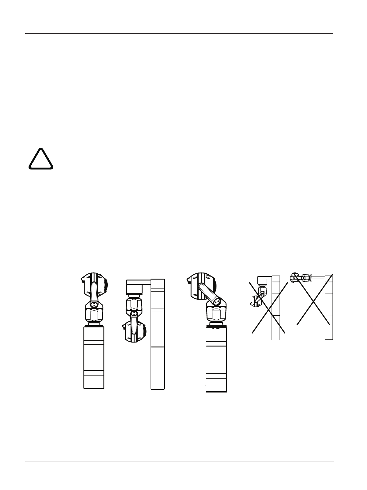
MIC cameras are designed to be mounted upright (straight up, 90°), inverted (straight down,
90°), or canted upright (ball up, 45°). The tilt limits for the canted unit prevent it from working
properly if mounted ball down. See the figures below for illustrations of the correct and the
incorrect mounting orientations of MIC cameras.
Correct mounting orientation -
upright, inverted
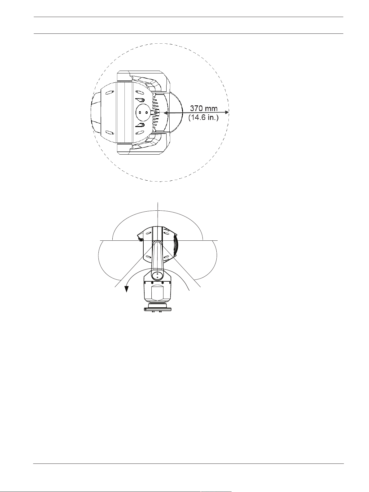
Note: For canted cameras, ensure that your mounting location provides the necessary
clearance (370 mm (14.6 in.)) for the camera head to pan.
2019-11 | 2.1 | Installation Manual Bosch Security Systems
Correct mounting orientation -
canted
Incorrect mounting orientation
MIC IP starlight 7000i Mounting | en 19
55° 55°
90° 90°
AutoPivot
Figure5.1: Top view of canted MIC7000 illustrating distance of pan clearance
The figure below illustrates the tilt range of the camera in upright orientation.
Figure5.2: MIC7000 Tilt Range: 145° each direction; 290° if AutoPivot enabled
Bosch Security Systems Installation Manual 2019-11 | 2.1 |
20 en | Mounting MIC IP starlight 7000i
MIC-SPR-BD,
-WD, -MG
MIC-SCA-BD,
-WD, -MG
MIC-WMB-BD,
-WD, -MG
5.3 Mounting Bracket Options
Bosch sells a complete series of mounting brackets that support multiple mounting
configurations.
Always use only Bosch-supplied mounts, which are designed for safe installation of your MIC
camera.
Refer to the MIC Series Mounting Brackets Installation Guide for complete installation
instructions.
Mounting hardware recommendations for MIC mounting accessories
Fasteners are not supplied with the MIC mounting accessories for attachment to the mounting
surface. The type of fastener necessary is dependent on the mounting surface.
Fasteners can include wedge anchors, sleeve anchors, single expansion anchors, double
expansion anchors, machine screws or ‘Thru-Bolting’ with a nut.
Fasteners are to be of a structural grade (ISO Class 10.9, SAE Grade 8) and zinc plated for
moderate corrosion resistance. When installed in marine or similarly corrosive environments,
stainless hardware (A2-800, A4-800) is recommended.
Fasteners are to be a minimum diameter of 8 mm (0.3125 in.).
All bolts must extend through the mounting surface and be secured with a flat washer, lock
washer and nut. All studs must be anchored to concrete or welded to a steel backing plate.
In all situations, Bosch recommends referencing any applicable building codes or professional
structural engineering guidelines for a secure installation.
Deep Conduit Adapter
The hinged DCA is well-suited to installations on top of a pole.
Typical hinged DCA mount configuration
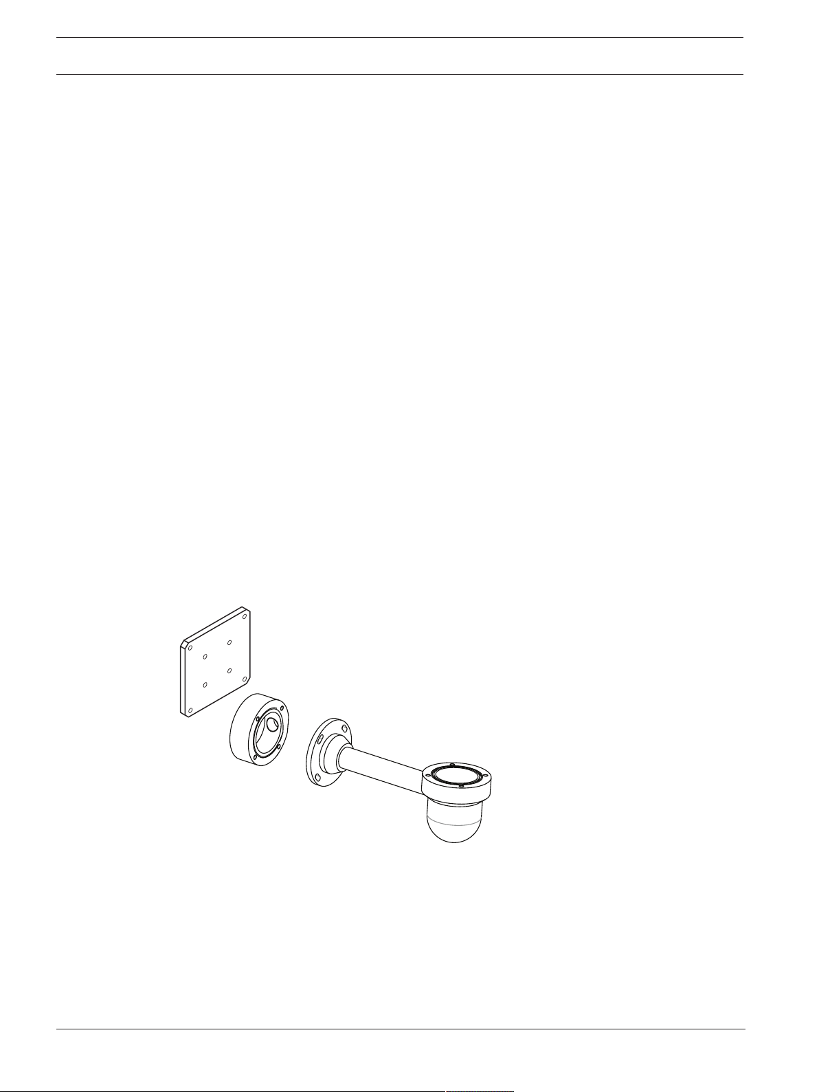
Wall Mount
Figure5.3: Typical Wall mount configuration
Note: Always install an SCA when you install a wall mount for any installation configuration.
Route cables through the bottom of the SCA (to prevent water from running into the side or
top of the SCA along the cables).
2019-11 | 2.1 | Installation Manual Bosch Security Systems
 Loading...