

Bosch GAM 270 MFL Operating/Safety Instructions
IMPORTANT:
Read Before Using
Operating/Safety Instructions
Consignes de sécurité/d’utilisation
Instrucciones de funcionamiento
y seguridad
IMPORTANT :
Lire avant usage
IMPORTANTE:
Leer antes de usar
GAM 270 MFL
1-877-BOSCH99 (1-877-267-2499) www.boschtools.com
Call Toll Free for
Consumer
Information and
Service Locations
For English Version
See page 7
Pour obtenir des informations
et les adresses de nos centres
de service après-vente, appelez
ce numéro gratuit
Version française
Voir page 19
Llame gratis para obtener
información para el consumidor
y ubicaciones de servicio
Versión en español
Ver la página 33
11
12
9
10
ab cdef fedcg
IN/FT
13
1
2
3
4
5
6
7
8
hi jkmihomkn
19 2018
15 16 1714
IN/FT
21
22
GAM 270 MFL
2
A
B
IN/FT
+
90°= 0% = 0 IN/FT
6
5
12 IN/FT =
IN/FT
+
C
D
0°= 0%= 0 IN/FT
w
3
E
1
4
w
10
4
w
1
F
4
H
G
21
1
v
w
4
21
1
w
v
4
5
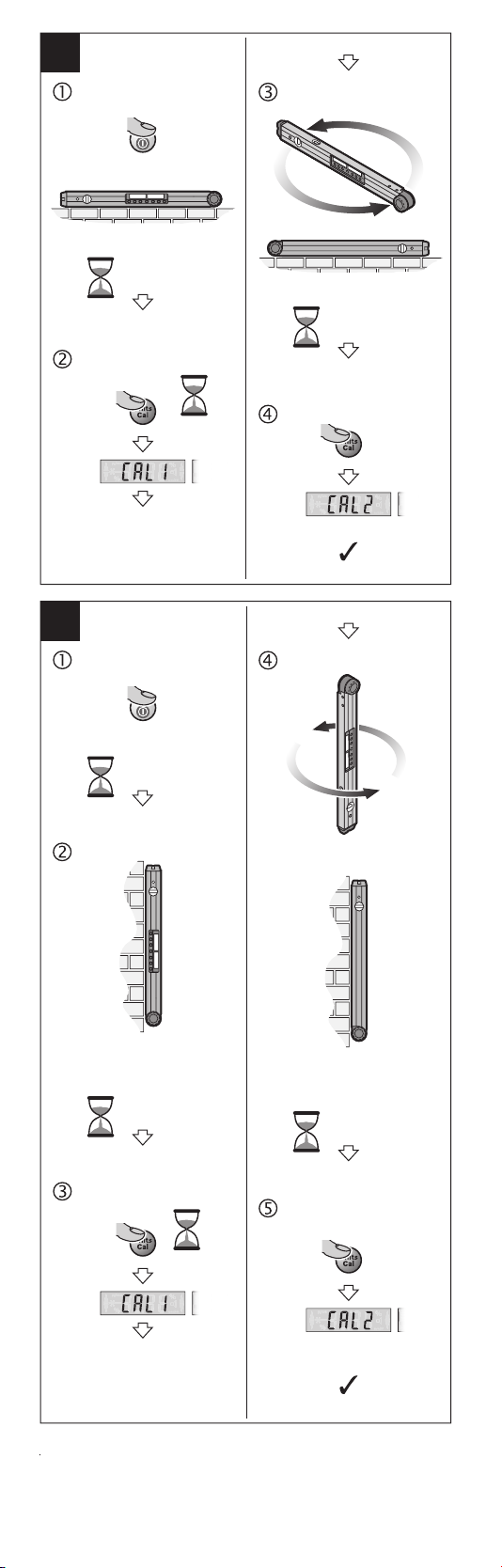
I
ON
180°
10 s
10 s
CAL
2 s
CAL
J
ON
10 s
10 s
180°
10 s
CAL
2 s
6
CAL

Safety Rules for Laser Measures
Read all instructions. Failure to fol-
result in hazardous radiation exposure, electric shock,
fire and/or serious injury.
The term “laser measure” in the warnings listed below
refers to your battery-operated (cordless) laser anglefinder/digital level.
SAVE ALL WARNINGS AND INSTRUCTIONS
The following label is on your
laser measure for your safety.
ALWAYS BE AWARE of its
location when using the laser
measure.
tion and complies with 21 CFR 1040.10 and 1040.11
except for deviations pursuant to Laser Notice No. 50,
dated June 24, 2007. This can lead to persons being
blinded.
low all instructions listed below may
FOR FUTURE REFERENCE
DO NOT direct the laser beam at persons
or animals and do
not stare into the laser beam yourself. This
laser measure produces class 2 laser radia-
DO NOT stare directly at the laser beam or project the
laser beam directly into the eyes of others. Serious eye
injury could result.
DO NOT place the laser measure in a position that may
cause anyone to stare into the laser beam intentionally
or unintentionally. Serious eye injury could result.
DO NOT operate the laser measure around children or
allow children to operate the laser measure. Serious eye
injury could result.
ALWAYS: Make sure that any bystanders in the vicinity
of use are made aware of the dangers of looking directly
into the laser measure.
Never aim the beam at a workpiece with a reflective
surface. Bright shiny reflective sheet steel or similar
reflective surfaces are not recommended for laser use.
Reflective surfaces could direct the beam back towards
the operator.
Use of controls or adjustments or performance of procedures other than those specified herein may result in
hazardous radiation exposure.
DO NOT use any optical tools such as, but not limited
to, telescopes or transits to view the laser beam. Seri-
ous eye injury could result.
DO NOT leave the laser measure “ON” unattended in
any operation mode. ALWAYS turn the laser measure
“OFF” when not in use. Leaving the laser measure “ON”
increases the risk of someone inadvertently staring into
the laser beam.
DO NOT operate the laser measure in combustible areas such as in the presence of flammable liquids, gases
or dust.
Do not use the laser viewing glasses as safety goggles.
The laser viewing glasses are used for improved visualization of the laser beam, but they do not protect against
laser radiation.
Do not use the laser viewing glasses as sun glasses or in
traffic. The laser viewing glasses do not afford complete
UV protection and reduce color perception.
ALWAYS position the laser measure securely. Damage to
the laser measure and/or serious injury to the user could
result if the laser measure falls.
Take care to recognize the accuracy and range of the
laser measure. Measurement may not be accurate if used
beyond the rated range of the laser measure.
DO NOT remove or deface any warning or caution labels. Removing labels increases the risk of exposure to
laser radiation.
7

Safety Rules for Anglefinders
When using the angle information provided by this tool
to cut materials, always observe all of your saw’s instructions, including those for positioning and clamping the
workpiece. In some cases, it may not be possible to set
the required angles on a particular saw or type of saw,
and an alternative means of performing the cut will need
to be used.
For extremely acute (sharp) angles, it may be necessary
to make the cut using a taper jig with a table saw or circular saw.
Electrical safety
Batteries can explode or leak, cause injury or fire. To reduce this risk, always follow all instructions and warnings on the battery label and package.
DO NOT short any battery terminals.
DO NOT charge alkaline batteries.
DO NOT mix old and new batteries. Replace all of them
at the same time with new batteries of the same brand
and type.
DO NOT mix battery chemistries.
Dispose of or recycle batteries per local code.
DO NOT dispose of batteries in fire.
Keep batteries out of reach of children.
Remove batteries if the device will not be used for sev-
eral months.
Maintenance
DO NOT disassemble the anglefinder/digital level. There
are no user serviceable parts inside. Disassembling the
anglefinder/digital level will void all warranties on the
product. Do not modify the product in any way. Modify-
ing the anglefinder/digital level may result in hazardous
laser radiation exposure.
DO NOT use this anglefinder/digital level for any purpose other than those outlined in this manual. This
could result in serious injury.
ALWAYS use only the accessories that are recommended by the manufacturer of your anglefinder/digital level.
Use of accessories that have been designed for use with
other anglefinder/digital levels could result in serious injury.
Repair and servicing must always be performed by a
qualified repair facility. Repairs performed by unquali-
fied personnel could result in serious injury.
8

Technical Data
Angle finder/Digital level GAM 270 MFL
Article number 3 601 K76 410
“HOLD” function ●
“Simple Miter” Operating Mode ●
“Compound Miter” Operating Mode ●
“Grade Measurement” Operating Mode ●
Display Illumination ●
Calibration ●
Measuring range 0°...270°
Measuring accuracy angle ±0.1°
Lowest indication unit 0.1°
Operating temperature 14 °F...122 °F
Storage temperature -4 °F...158 °F
Alkaline Batteries 4 x1.5V LR6 (AA)
Operating time approx.
1
Automatic switch-off after approx. 30 min
Leg length 23.6 in (600 mm)
Weight according to EPTA-Procedure
01/2003
Measuring range of grade measuring device
– 0°/90°
– 1°–89°
Working range of laser
2
Vertical levelling accuracy of laser ±0.5 mm/m
Horizontal levelling accuracy of laser ±1 mm/m
Clearance of laser exit – bottom edge of
anglefinder/digital level
Laser class 2
Laser type 650 nm, < 1 mW
Laser beam diameter (at 25 °C) approx.
– at 5 m distance
– at 10 m distance
Relative air humidity, max. 90 %
Dimensions
(length x width x height)
IP 54 (dust and splash proof) ●
(–10 °C...+50 °C)
(–20 °C...+70 °C)
50 h
3.3 lbs (1.5 kg)
±0.05°
±0.1°
100 ft (30 m)
1.2 in (30 mm)
0.1 in (3 mm)
0.3 in (8 mm)
26.9 x 2 x 2.4 in
(684 x 52 x 60 mm)
1)
Operating duration without laser
2)
The working range can be decreased by unfavorable
environmental conditions (e.g. direct sun irradiation).
The anglefinder/digital level can be clearly identified
with the serial number 13 on the type plate.
Intended Use
The anglefinder/digital level is intended for measuring
and transferring angles and for calculating simple and
compound miter angles, checking and aligning horizontals and verticals. It is suitable for indoor and outdoor
use.
9

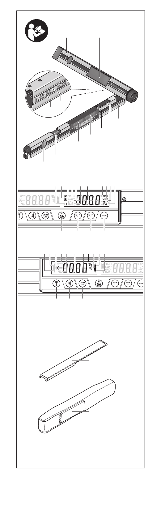
Features
The numbering of the product features shown refers
to the illustration of the anglefinder/digital level on the
graphic page.
1 Fold-out leg
2 Viewing window for
display
3 Locking wheel
4 Base leg
5 Battery lid
6 Latch of battery lid
7 Display Angle measur-
ing device
8 Display Grade measur-
ing device
9 Spirit level for horizon-
tal alignment
10 Spirit level for vertical
alignment
11 Laser beam outlet
opening
Display elements
The numbering of the product features shown refers
to the illustration of the anglefinder/digital level on the
graphic page.
a “H” indicator for “HOLD” memory value
b Battery indicator
c Bevel angle indicator “BVL”
d Miter angle indicator “MTR”
e Corner angle indicator “CNR”
f Spring angle indicator “SPR”
g Reading Angle measuring device
h/i Alignments arrows
j Laser operation indicator
k/m Unit of measure indicator
n Measuring value Grade Measurement
o Indicator for audio signal
12 Laser warning label
13 Serial number
14 “ON/OFF” button
15 “MTR1” button for
simple miter
16 “MTR2” button for
compound miter
17 “HOLD” button
18 On/Off button for laser
beam
19 Audio signal button
20 Calibration/change
units button
21 Leg extension
22 Protective pouch
Assembly
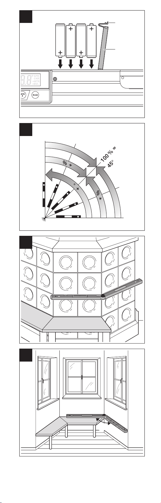
Inserting/Replacing the Batteries
Use alkaline (4 x AA) batteries to operate the anglefinder/
digital level.
Ensure polarity of each battery
correct battery polarity may cause fire or personal injury.
To open the battery lid 5, press on the latch 6 and fold the
battery lid up. Insert the batteries (Fig. A).
Battery Indicator
The battery indicator b always displays the current battery status:
The battery is over 90 % full
The battery is between 60 % and 90 % full
The battery is between 30 % and 60 % full
The battery is between 10 % and 30 % full
The empty battery indicator flashes. The battery
level is under 10 %. Once the battery indicator begins flashing, you can measure for approximately
another 15-20 minutes until the tool shuts down.
Always replace all batteries at the same time. Do not use
different brands or types of batteries together.
Remove the batteries from the angle finder/digital level
when not using it for longer periods. When storing for
longer periods, the batteries can corrode and self-discharge.
Slide the leg extension 21 onto the fold-out leg 1 from the
front. Slide the leg extension as far as possible over the
joint of the anglefinder/digital level.
matches the instructions in Fig. A. In-
Mounting the Leg Extension
10

Operation
Initial Operation
Protect the anglefinder/digital level
against moisture and direct sun light.
Do not subject the anglefinder/digital
ations in temperature. As an example, do not leave it in
vehicles for a long time. In case of large variations in temperature, allow the anglefinder/digital level to adjust to
the ambient temperature before putting it into operation.
In case of extreme temperatures or variations in temperature, the accuracy of the anglefinder/digital level can be
impaired.
severe exterior effects to the anglefinder/digital level, it is
recommended to carry out an accuracy check (see “Accuracy Check and Calibration of the Anglefinder/digital
level”, page 22) each time before continuing to work.
must be clean. Protect the anglefinder/digital level
against impact and shock. Debris particles or deforma-
tions can lead to faulty measurements.
Do not leave the switched-on anglefinder/digital level
unattended and switch the anglefinder/digital level off
after use. Other persons could be blinded by the laser
beam.
Press the “ON/OFF” switch 14 to switch the anglefinder/
digital level on or off.
If the “H” indicator lights up, the value from the last
measurement is still saved. This value can be deleted by
briefly pressing the “ON/OFF” button 14.
The anglefinder/digital level will shut down after approx.
30 minutes of inactivity to preserve battery life.
The anglefinder/digital level can be aligned horizontally
with spirit level 9 and vertically with spirit level 10.
When you rotate the measuring device 180°, the display
will also rotate automatically to make the displayed value
easier to read.
After switching on, the anglefinder/digital level is always
in normal measuring mode.
In “Normal Measuring” mode, angle measurement and
grade measurement are carried out simultaneously.
Angle Measurement Operating Mode
The anglefinder/digital level is in the “Angle Measurement” operating mode every time it is switched on.
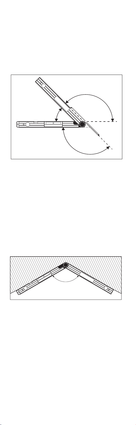
Measuring Angles (see figures C–D)
Place the fold-out leg 1 and the base leg 4 flat on the
surfaces around the angle you wish to measure. The
measured angle value w will display on the display 7 as
measured value c. The measured value will remain on the
display until the angle between fold-out leg 1 and base
leg 4 has changed.
Once you have your desired angle measurement (see
Measuring Angles section), lock the position of the legs
by tightening the locking wheel 3.
Place the anglefinder/digital level in the desired position
against the workpiece. Use the legs as a straight edge to
transfer the angle.
Press the “HOLD” memory button 17 to save the current
measuring value. The a indicator will flash on the display
as confirmation. The currently displayed value is frozen
and will not change even when the leg is moved. If you
press the “HOLD” memory button again, the a indicator
will permanently be shown on the display. The displayed
value will change if you move the legs. The previously frozen value is now saved in the background. If the “HOLD”
memory button 17 is pressed again, the previously saved
value is displayed and the a indicator flashes.
The unit can only store one value at a time. Storing a new
value will automatically overwrite the previously stored
value.
level to extreme temperatures or vari-
Avoid heavy impact to or falling down
of the anglefinder/digital level. After
The contact surfaces and contact
edges of the anglefinder/digital level
Switching On and Off
Aligning with the Spirit Levels
Rotating the Display
“Normal Measuring Mode”
Transferring Angles (see figure E)
Save measured values
11
The held value is saved even when the anglefinder/digital
level is switched off (manually or automatically). However, it is deleted when changing batteries or when the
batteries are empty.
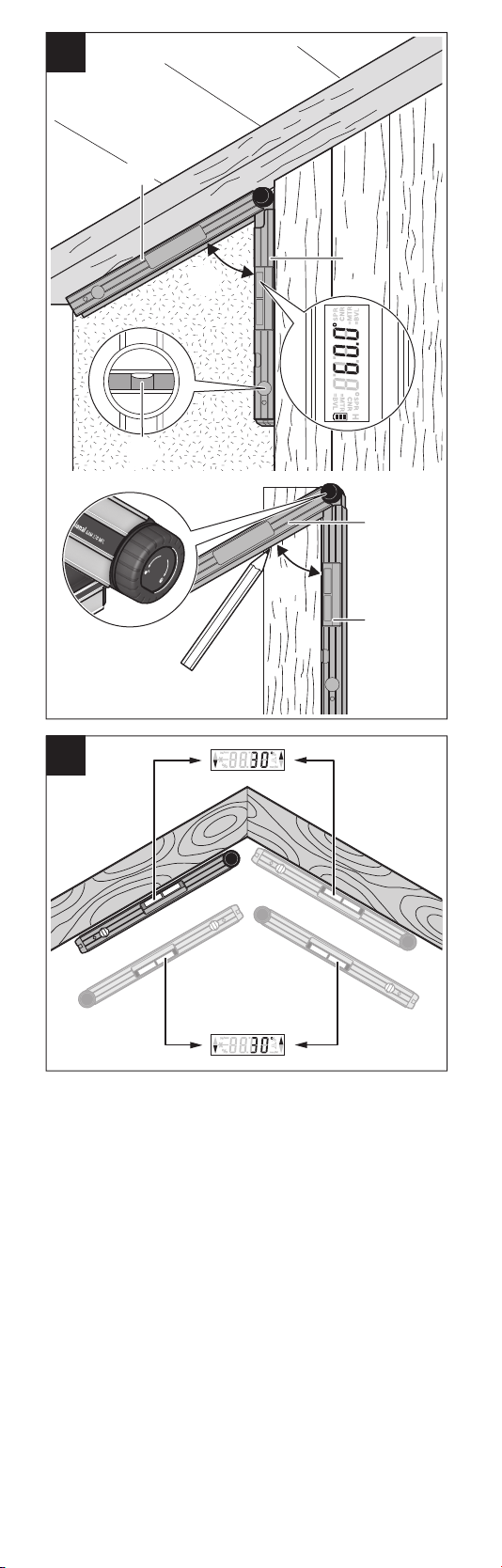
Measuring with Leg Extension (see figures G–H)
The leg extension 21 enables angle measurement when
the contact surface is shorter than the fold-out leg 1.
Place the base leg 4 and the leg extension flat on or
against the edges to be measured.
The reading of the angle w between base leg and fold-out
leg is indicated in the display. The required angle v be-
tween base leg and leg extension is calculated as follows:
v = 180° – w
v
w
v
“Simple Miter”Operating Mode
The “Simple MTR” operating mode is used to determine
miter angles for miter cuts that are made with the blade
vertically perpendicular to the workpiece; in other words,
miter cuts for which the bevel setting is set at 0°. Such
applications include mitering baseboard and chair rail,
picture rails, door frames, staircase balusters, and picture
The “Simple Miter” operating mode is activated by pressing the “MTR1” button. The displayed value is always
used for the calculation of the “MTR”. If a saved value
is being displayed (indicator a flashes), the calculation
will be performed with the saved value regardless of the
position of the legs.
x
°
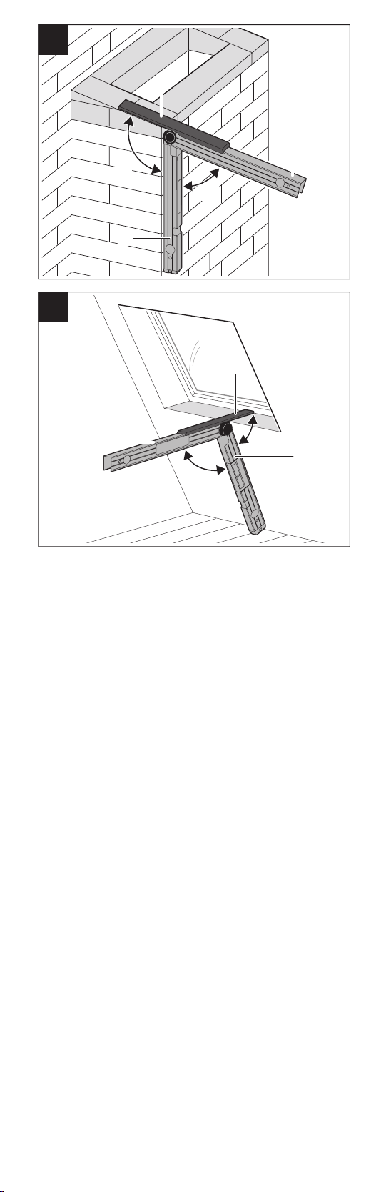
When workpieces are to be fitted into a corner (e.g. for
floor trimmings), measure the corner angle x° by applying
the fold-out leg and the base leg. For given angles (e.g.
picture frames), open the fold-out leg and the base leg
until the desired angle is indicated in the display.
12

MTR
MTR
x
°
x
°
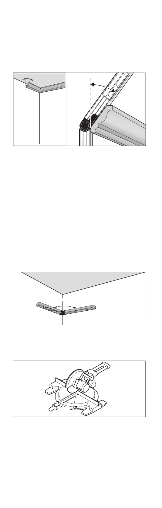
The miter angle “MTR”, by which the two workpieces are
to be shortened, is calculated. For these miter cuts, the
saw blade is vertical to the workpiece (the bevel angle
is 0°).
MTR
Press button 15. The calculated horizontal miter angle
“MTR”, which has to be set on the chop and miter saw,
and the “MTR” indicator will be shown on the display.
Press the “MTR1” button 15 to return from the “Simple
Miter” operating mode to the “Angle Measurement” operating mode.
Pressing the “ON/OFF” button will also take you back to
the “Angle Measurement” operating mode.
Note: The calculated miter angle “MTR” can only be tak-
en over for chop and miter saws, for which the setting for
vertical cuts is 0°. When the setting for vertical cuts is
90°, the angle for the saw must be calculated as follows:
90° – indicated “MTR” angle = angle to be set on the saw.
13
“Compound Miter” Operating Mode
The “Compound MTR” operating mode is used to easily
determine the miter and bevel angles needed to create
precision joints at compound angles. This is particularly
useful when cutting crown molding laid flat on a compound miter saw.
The “Compound Miter” operating mode is activated by
pressing the “MTR2” button.
Carry out the worksteps exactly in the given sequence.
“1. SPR”: Storing the Spring Angle
SPR
To start “Compound Miter” calculation:
– Open the fold-out leg and base leg until the desired
spring angle is shown on the display.
– Measure the spring angle if it is unknown. To
do so, place the workpiece you want to measure between the fold-out leg and the base leg.
If measurement is not possible with the anglefinder/
digital level on especially narrow or small workpieces,
use auxiliary equipment, e.g. a bevel, and then set the
angle on the anglefinder/digital level.
– To use a saved “HOLD” value (indicator a is static on
the display), press “HOLD,” previously saved angle
will flash. Press “MTR2” and held angle will blink
twice with “SPR” indicator flashing. Continue with
step 2 below.
When the angle is greater than 90° yet less than 180°
when pressing button 16, the “SPR” spring angle is automatically converted as follows:
“SPR” = 180° – measured or set angle.
“2. CNR”: Storing the Corner Angle
SPR
SPR
CNR
To measure the corner angle, place the fold-out and base
legs flat against the walls and read the measured corner
angle or set a known corner angle on the anglefinder/
digital level.
“3.MTR”: Calculating the Miter Angle
MTR
Press button 16 again. “MTR” and the calculated miter
angle for the chop and miter saw are indicated on the
display.
14
 Loading...