

Bosch D7050TH Installation Manual
D7050/D7050TH
Installation Instructions
EN
Multiplex Photoelectric
Smoke Detectors
D7050/D7050TH | Installation Instructions | 1.0 Description
Notices
These instructions cover the installation of the
D7050/D7050TH Multiplex Photoelectric Smoke
Detectors on a D7024 or DS9400M 24 VDC Fire
Alarm Control Panel (FACP) with a D7039 or DS9431
Multiplex Expansion Module installed. The D7024 and
DS9400M FACPs require ROM version 2.0 or greater.
Install, test, and maintain the D7050/D7050TH
according to these instructions, NFPA 72, local codes,
and the Authority Having Jurisdiction (AHJ).
Follow the procedures in these instructions
to avoid personal injury and damage to
This device complies with Part 15 of the Federal
Communications Commission (FCC) Rules and with
RSS-210 of Industry and Science Canada. Operation is
subject to the following conditions:
• This device does not cause harmful interference.
• This device must accept any interference received,
equipment. Failure to follow the procedures
can cause the D7050-D7050TH to not
operate properly. Bosch is not responsible
for improperly installed, tested, or
maintained devices.
including interference that might cause undesirable
operation.
1.0 Description
The D7050/D7050TH are Underwriters Laboratories,
Inc. (UL) Listed, open-area multiplex photoelectric
smoke detectors. The D7050TH includes a built-in
+135°F ± 5°F (+57°C ± 2.7°C) heat detector. Both
detectors can be used with the D7024 or DS9400M
FACP containing a D7039 or DS9431 Module.
Each detector uses a D7050-B6 or MXB2W detector
base.
For commercial and industrial installations, space the
D7050/D7050TH 30 ft (9.2 m) according to NFPA 72.
Wall-mounted smoke detectors must be at
least 4 in. (10.2 cm) and no more than 12
An LED indicator flashes every 3 to 8 sec confirming
the detector has power and the smoke sampling
circuitry functions. The LED flashes at least once each
second in an alarm allowing you to easily confirm
individual detector alarms. The detector automatically
resets after the alarm condition clears.
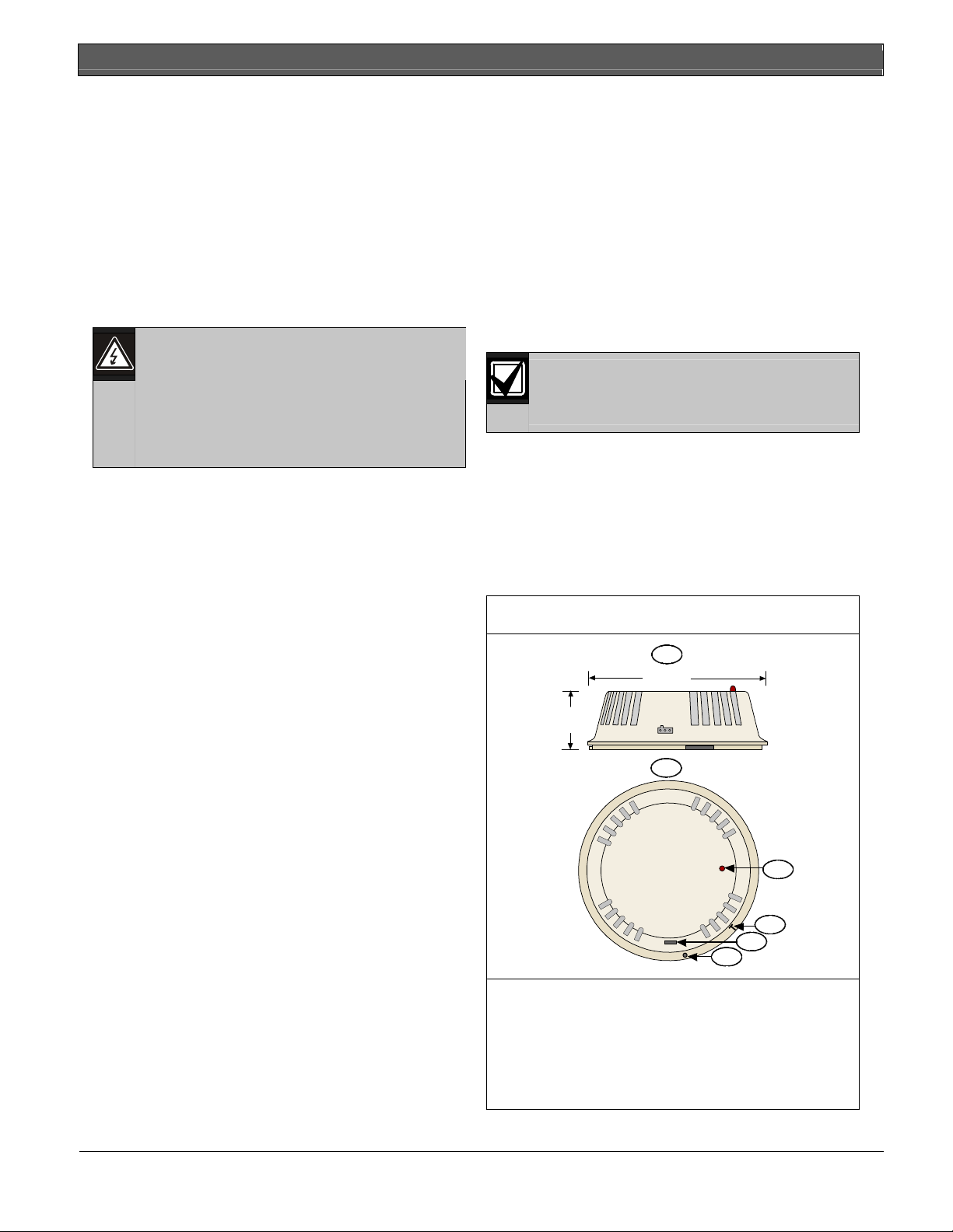
Refer to Figure 1 for the D7050/D7050TH’s dimensions
and components.
Figure 1: D7050/D7050TH Side and Top Views
in. (30.5 cm) below the ceiling.
4 in.
(10.2 cm)
1.5 in.
(3.8 cm)
1 - Side view
2 - Top view
3 - Alarm/Test LED
4 - Magnetic test locator
5 - Calibration voltage pins
6 - Tamper screw hole
1
2
3
4
5
6
2 Bosch Security Systems, Inc. | 9/06 | 47458E
.
2.0 Installation
D7050/D7050TH | Installation Instructions | 2.0 Installation
3.0 Wiring the D7050-B6 Base
Do not use shielded cable.
For multiplex bus wiring requirements, refer to the
D7024 Operation and Installation Guide (P/N: 31799), the
DS9400M Reference Guide (P/N: 44578), the D7039
Installation Guide (P/N: 38685), or the DS9431
Installation Instructions (P/N: 41381).
Do not exceed a maximum line resistance
of 50 Ω.
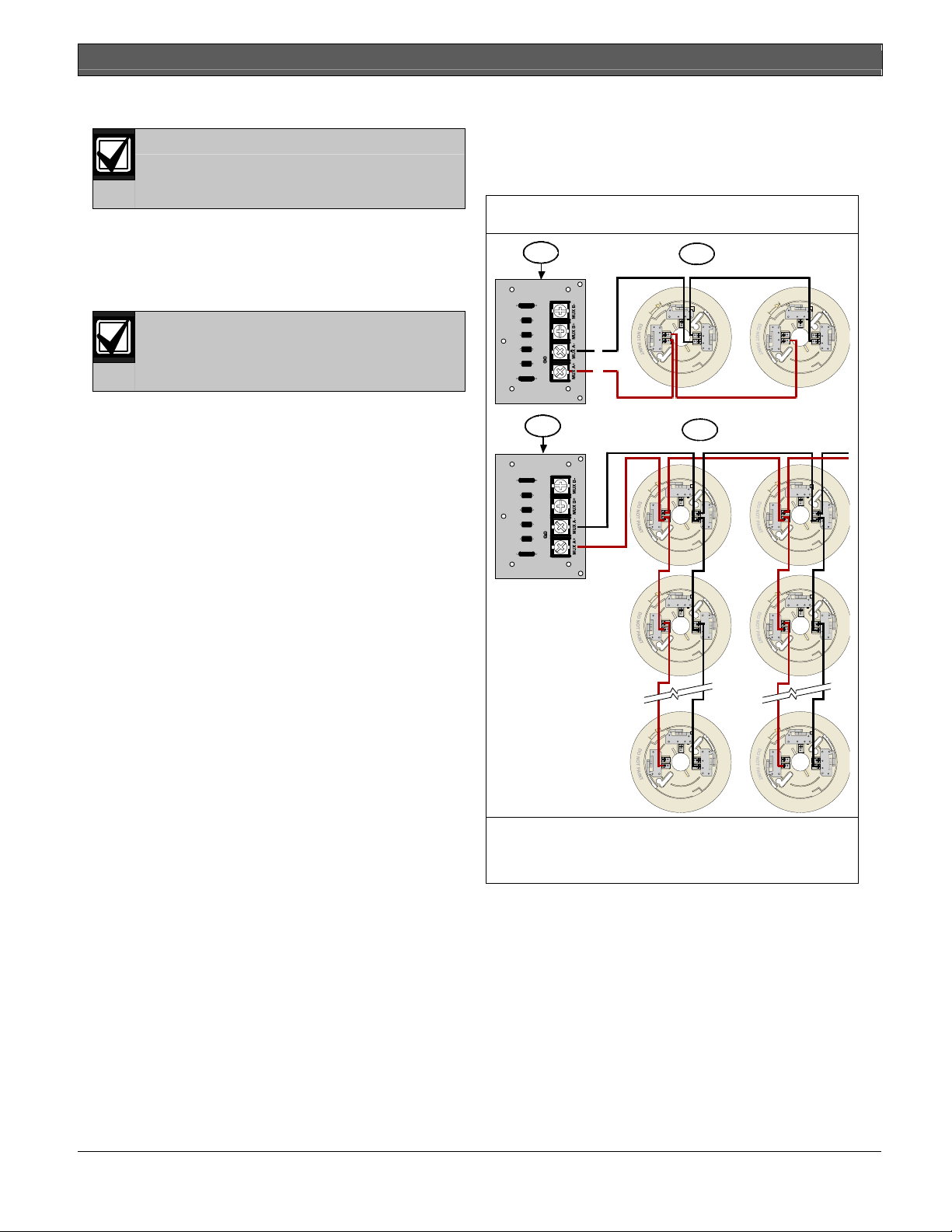
You can wire the D7050-B6 Base in series or T-tap
(refer to Figure 2).
Figure 2: Wiring the D7050-B6 Base
1
(-)
(+)
1
2
R2
+1
3-
R2
+1
3-
3
R2
+1
3-
R2
+1
3-
R2
+1
3-
R2
+1
3-
R2
+1
3-
R2
+1
3-
1 - Input-output module for the D7039 or DS9431
2 - Series connection
3 - T-tap connection
You can replace the dust cover during construction
periods, but it must be removed once the alarm system
is enabled.
Bosch Security Systems, Inc. | 9/06 | 47458E 3
 Loading...